

Follett HCD700RN Service Manual
HCD700R/N, HMD700R/N
Ice Machines
Order parts online
www.follettice.com
Operation and Service Manual
Serial Numbers After H58642
Following installation, please forward this manual
to the appropriate operations person.
801 Church Lane • Easton, PA 18040, USA
Toll free (877) 612-50861 • +1 (610) 252-7301
www.follettice.com
01012715R07

2 Horizon HCD700R/N, HMD700R/N Ice Machines

Table of contents
Welcome to Follett Corporation .................................................................................................................................. 4
Specications .............................................................................................................................................................. 5
Operation ....................................................................................................................................................................... 7
Cleaning, weekly exterior care .............................................................................................................................. 7
Cleaning, semi-annual evaporator cleaning .......................................................................................................... 7
Service ......................................................................................................................................................................... 12
Ice machine operation ......................................................................................................................................... 12
Water system....................................................................................................................................................... 13
Electrical system ................................................................................................................................................. 14
Normal control board operation ................................................................................................................... 14
Test points .................................................................................................................................................... 15
Error faults ................................................................................................................................................... 15
Hard errors ................................................................................................................................................... 15
Soft errors .................................................................................................................................................... 15
Relay output indication ................................................................................................................................. 15
Compressor/refrigerant solenoid output ....................................................................................................... 15
Wiring diagram, evaporator unit ................................................................................................................... 16
Wiring diagram, condenser unit ................................................................................................................... 17
Gearmotor data ............................................................................................................................................ 17
Mechanical system .............................................................................................................................................. 18
Evaporator disassembly ............................................................................................................................... 18
Evaporator reassembly ................................................................................................................................ 20
Refrigeration system ........................................................................................................................................... 23
Condenser unit operation ............................................................................................................................ 23
Refrigerant pressure data ............................................................................................................................ 23
Refrigerant charges ..................................................................................................................................... 23
Refrigeration system diagram ...................................................................................................................... 24
Refrigerant replacement requirements ........................................................................................................ 25
Evacuation ................................................................................................................................................... 25
Ambients (evaporator unit) ........................................................................................................................... 25
Ice capacity test ........................................................................................................................................... 25
Bin full detection system ..................................................................................................................................... 26
Troubleshooting ................................................................................................................................................... 27
Replacement parts .............................................................................................................................................. 30
Horizon HCD700R/N, HMD700R/N Ice Machines 3
Welcome to Follett
Follett equipment enjoys a well-deserved reputation for excellent performance, long-term reliability and outstanding
after-the-sale support. To ensure that this equipment delivers the same degree of service, we ask that you review
the installation manual (provided as a separate document) before beginning to install the unit. Our instructions are
designed to help you achieve a trouble-free installation. Should you have any questions or require technical help at
any time, please call our technical service group at (877) 612-5086 or
+1 (610) 252-7301.
Before you begin
After uncrating and removing all packing material, inspect the equipment for concealed shipping damage. If damage
is found, notify the shipper immediately and contact Follett Corporation so that we can help in the ling of a claim, if
necessary.
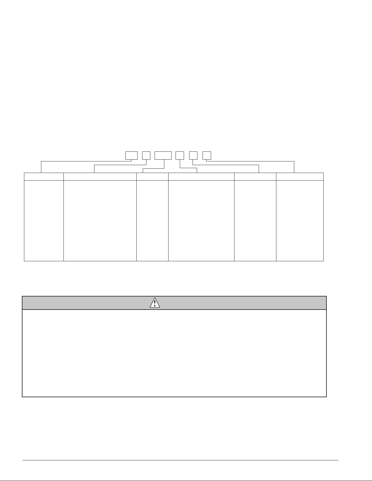
Check your paperwork to determine which model you have. Follett model numbers are designed to provide information
about the type and capacity of Follett equipment. Following is an explanation of the different model numbers in the 700
series.
Chewblet® Ice Machine Model Number Configurations
A V SC 700HC
ConfigurationApplication
®
S RIDE
(RIDE remote ice
delivery equipment)
T Top-mount
MC Maestro™
Chewblet
(400 Series)
HC Horizon
Chewblet
(1000, 1400,
1650 Series)
HM Horizon
Micro
Chewblet
C 208-230/60/1 (icemaking head)
Self-contained only.
D 115/60/1 (icemaking head)
Self-contained and remote.
If remote unit, high side is
208-230/60/1.
E 230/50/1 (icemaking head)
Self-contained only.
F 115/60/1 (icemaking head)
Remote only. High side is
208-230/60/3.
400 up to
454 lbs
(206kg)
700 up to
750 lbs
(340kg)
1000 up to
1036 lbs
(471kg)
1400 up to
1450 lbs
(658kg)
1650 up to
1580 lbs
(717kg)
CondenserSeriesVoltageMachine
A Air-cooled, self-contained
W Water-cooled,
self-contained
R Air-cooled, remote
condensing unit
N Air-cooled, no condensing
unit for
connection to parallel rack
system
V Vision™
H Harmony™
B Ice storage
bin
J Drop-in
M Ice Manager™
diverter valve
system
CAUTION
§ Outdoor installation of low side is not recommended and will void warranty.
§ Moving parts. Do not operate with front cover removed.
§ Hot parts. Do not operate with cover removed.
§ To reduce risk of shock, disconnect power before servicing.
§ To prevent circuit breaker overload, wait 15 minutes before restarting this unit. This allows the compressor to
equalize and the evaporator to thaw.
§ Most ice machine cleaners contain citric or phosphoric acid, which can cause skin irritation. Read caution
label on product and follow instructions carefully.
§ Ice is slippery. Maintain counters and oors around dispenser in a clean and ice-free condition.
§ Ice is food. Follow recommended cleaning instructions to maintain cleanliness of delivered ice.
4 Horizon HCD700R/N, HMD700R/N Ice Machines
Specications
Electrical
Separate circuit and equipment ground required.
Evaporator unit
Standard electrical: 115/60/1
Maximum fuse: 15A
Amperage: 6A
Condensing unit
Single-Phase
Electrical 208-230V, 60Hz
Maximum Circuit HVACR breaker size 15A
Minimum Circuit Ampacity 10.7A
Evaporator plumbing
§ 3/8" OD push-in water inlet
§ 3/4" MPT
§ 3/4" vented drain line must slope a minimum of 1/4" per foot (6 mm per 30.4 cm run).
§ Drain to be hard piped and insulated.
§ Water shut-off recommended within 10 feet (3 m).
§ Follett recommends installation of Follett water lter system (part# 00130286) in ice machine inlet water line.
Ambient
Evaporator unit
Air temperature 100 F/38 C max. 50 F/10 C min.
Water temperature 90 F/32 C max. 45 F/7 C min.
Water pressure 70 psi max. (483 kPa) 10 psi min. (69 kPa)
Condenser unit
Air temperature 120 F/49 C max. –20F/–29C min.
Refrigeration
§ 3/8" liquid line
§ 5/8" suction line
Note: Rack system installations require a capacity of 6,000 BTU/hr at 0 F (–18 C) evaporator temperature.
Evaporator pressure regulator (not supplied) is required.
Weight
Evaporator unit: 125 lbs (57 kg)
Condensing unit: 225 lbs (102 kg)
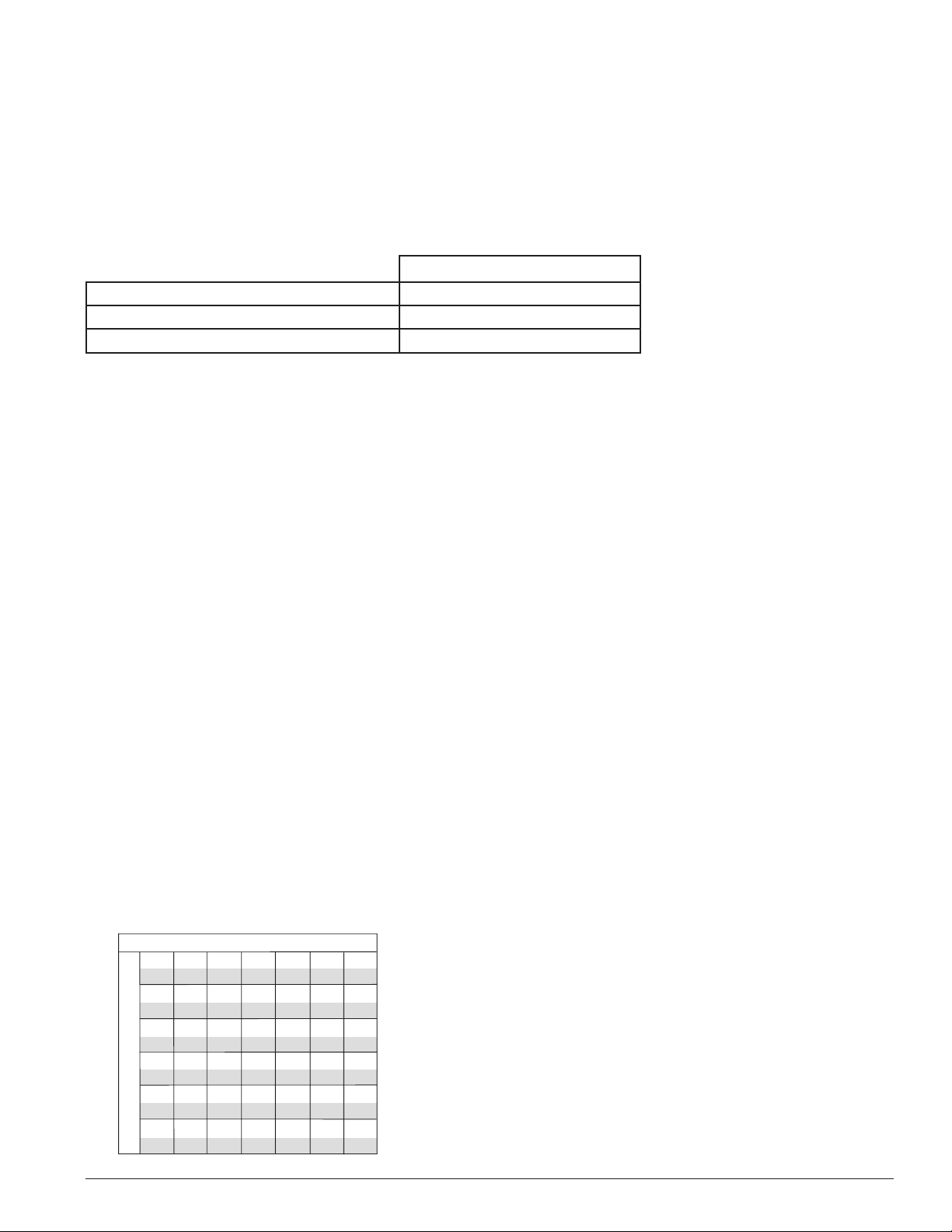
Ice production
Air-cooled ice machine capacity/24 hrs.
Ambient Air Temperature F/C
60
70
80
90
32
586
266
559
254
528
239
506
230
499
226
100
38
565
256
529
240
512
232
478
217
441
200
lbs
kg
lbs
kg
lbs
kg
lbs
kg
lbs
kg
F
16
C
747
50
339
10
714
60
324
16
671
70
304
21
649
80
294
27
600
90
272
32
Inlet Water Temperature F/C
21
678
308
673
305
643
292
609
276
583
264
27
644
292
618
280
589
267
561
254
535
243
Horizon HCD700R/N, HMD700R/N Ice Machines 5
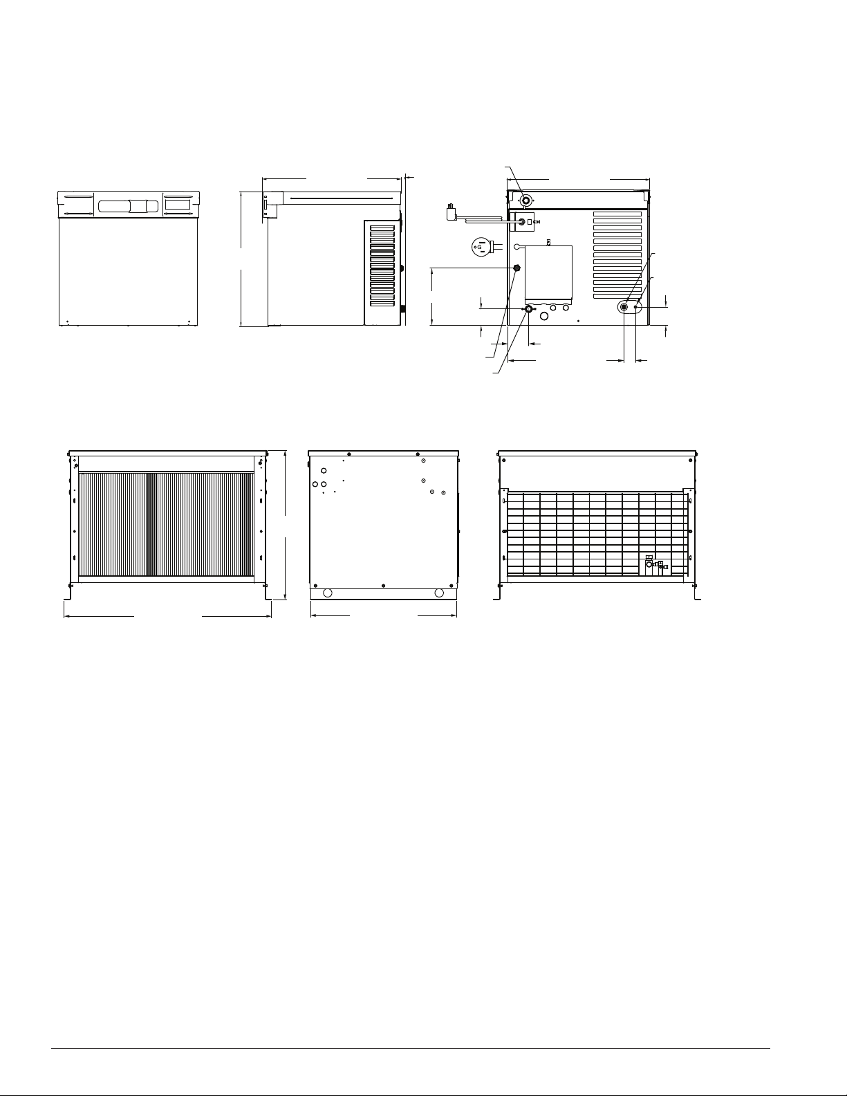
Dimensions and clearances
Entire front of ice machine must be clear of obstructions/connections to allow removal.
§ 1" (26 mm) clearance above ice machine for service.
§ 1" (26 mm) minimum clearance on sides.
Front View Side View Back View
ICE TRANSPORT HOSE CONNECTION
1.75"
(44.5 mm) MIN.
NEMA 5-15P
RIGHT ANGLE
9.00" (22.9 cm)
2.56" (65 mm)
3.29" (84 mm)
3/4" MPT DRAIN
18.23" (46.3 cm)
Single-Phase Condensing Unit
21.25
(54 cm)
22.44" (57 cm)
"
3/8" OD PUSH-IN WATER INLET
22.46" (57 cm)
5/8" SUCTION LINE
3/8" LIQUID LINE
2.88" (73 mm)
1.81" (46 mm)
36.25" (92.1 cm)
26.08
(66.3 cm)
"
25.50" (64.8 cm)
6 Horizon HCD700R/N, HMD700R/N Ice Machines
Operation
Cleaning and preventive maintenance (all models)
Note: Do not use bleach to sanitize or clean the ice machine.
Preventive maintenance
Periodic cleaning of Follett’s ice machine system is required to ensure peak performance and delivery of clean,
sanitary ice. The recommended cleaning procedures that follow should be performed at least as frequently as
recommended, and more often if environmental conditions dictate.
Cleaning of the condenser can usually be performed by facility personnel. Cleaning of the ice machine system, in
most cases, should be performed by your facility’s maintenance staff or a Follett authorized service agent. Regardless
of who performs the cleaning, it is the operator’s responsibility to see that this cleaning is performed according to the
schedule below. Service problems resulting from lack of preventive maintenance will not be covered under the Follett
warranty.
Weekly exterior care
The exterior may be cleaned with a stainless cleaner such as 3M Stainless Steel Cleaner & Polish or equivalent.
Monthly condenser cleaning (air-cooled ice machine only)
1. Use a vacuum cleaner or stiff brush to carefully clean condenser coils of air-cooled ice machines to ensure
optimal performance.
2. When reinstalling counter panels in front of remote ice machines, be sure that ventilation louvers line up with
condenser air duct.
Semi-annual evaporator cleaning (every 6 months)
WARNING
§ Wear rubber gloves and safety goggles (and/or face shield) when handling ice machine cleaner or sanitizer.
CAUTION
§ Use only Follett approved SafeCLEAN™ Cleaner (part #00132001) and NU-CALGON IMS-II or IMS-III
SANITIZER.
§ Do not mix Cleaner and Sanitizer solutions together.
§ DO NOT USE BLEACH.
§ It is a violation of Federal law to use these solutions in a manner inconsistent with their labeling.
§ Read and understand all labels printed on packaging before use.
Note: Complete procedure for cleaning an sanitizing MUST be followed. Ice must be collected for 10minutes
before putting ice machine back into service.
Fig. 1
1. To clean – Remove cover. Press the CLEAN button. The
machine will drain. Wait for the LO WATER light to come
on (Fig. 1).
LO WATER
Horizon HCD700R/N, HMD700R/N Ice Machines 7

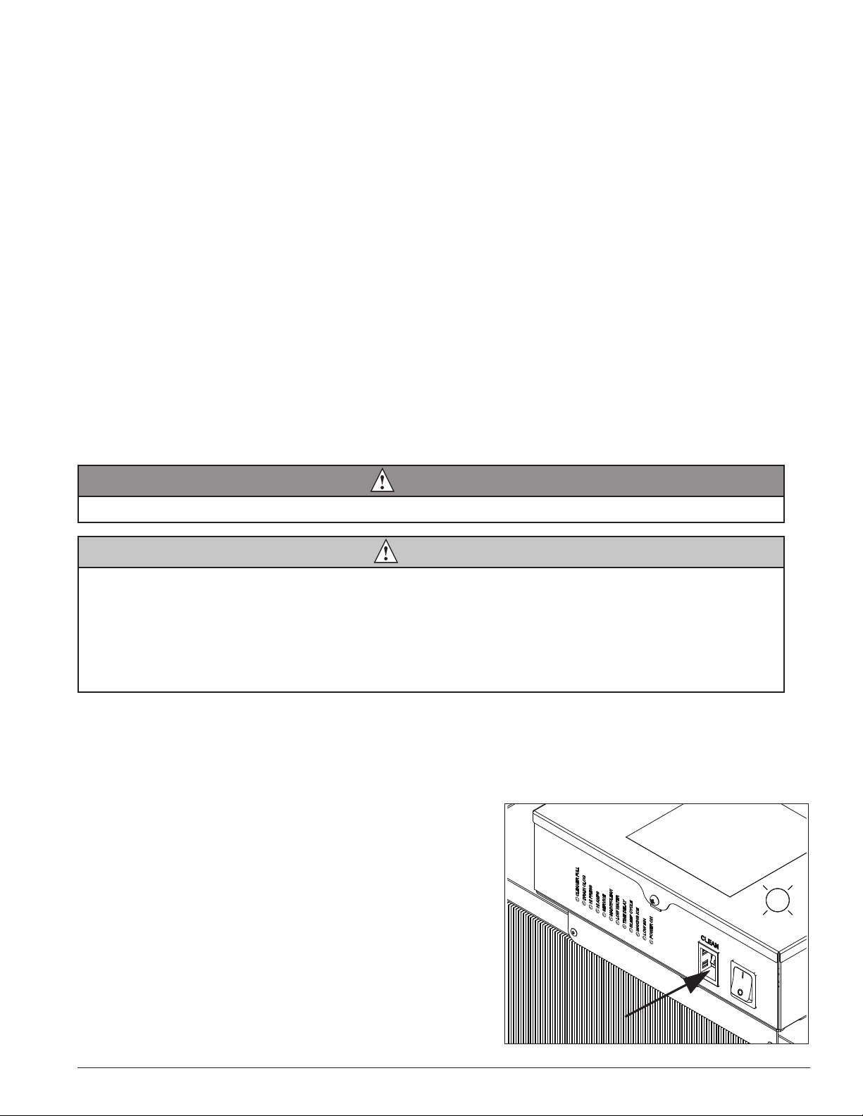
2. Mix 1 gallon (3.8L) 120 F (49 C) water and
7 ounces (198g) (one 7 ounce packet of Follett
SafeCLEAN ice machine cleaner, part# 00132001).
Locate cleaning cup. Fill until CLEANER FULL light
comes on (Fig. 2).
Note: Do not use bleach to sanitize or clean the ice
machine.
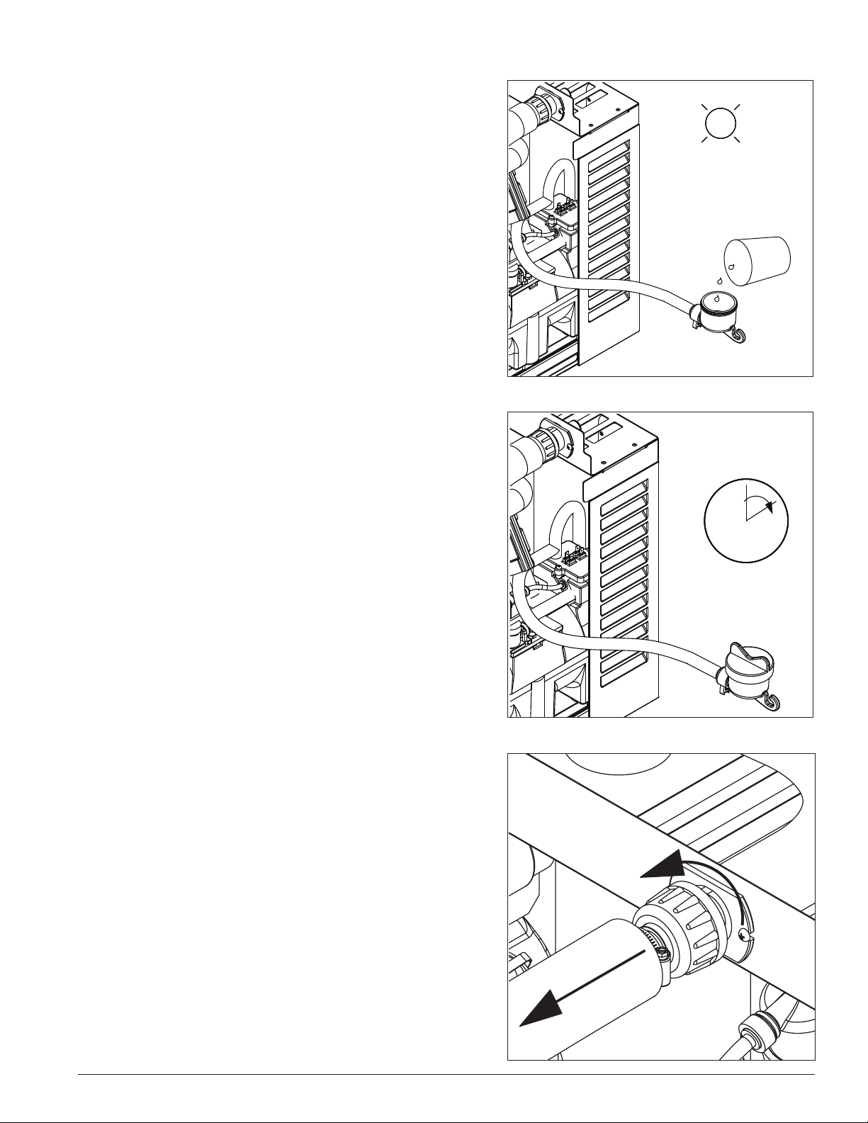
3. Replace cover on cleaning cup. Wait until machine
restarts. Machine will clean, then ush 3 times in
approximately 15 minutes (Fig. 3).
Fig. 2
CLEANER
FULL
Fig. 3
4. To sanitize – Press CLEAN button. The machine will
drain. Wait for LO WATER light to come on
(Fig. 4).
15
Fig. 4
LO WATER
8 Horizon HCD700R/N, HMD700R/N Ice Machines
5. Mix 1 gallon 120 F (49 C) water and 1.6 ounces (48ml)
NU-CALGON IMS-II or IMS-III SANITIZER. Fill until
CLEANER FULL light comes on (Fig. 5).
Place one Sani-Sponge™ in remaining sanitizing solution
and retain for Step 9.
Note: Do not use bleach to sanitize or clean the
ice machine.
6. Replace cover on cleaning cup. Wait until machine
restarts. Machine will clean, then ush 3 times in
approximately 15 minutes (Fig. 3).
Fig. 5
CLEANER
FULL
Fig. 6
7. Disconnect coupling as shown (Fig. 7).
Note: Steps 8-11 must be completed before machine
ushes and starts producing ice.
15
Fig. 7
Horizon HCD700R/N, HMD700R/N Ice Machines 9
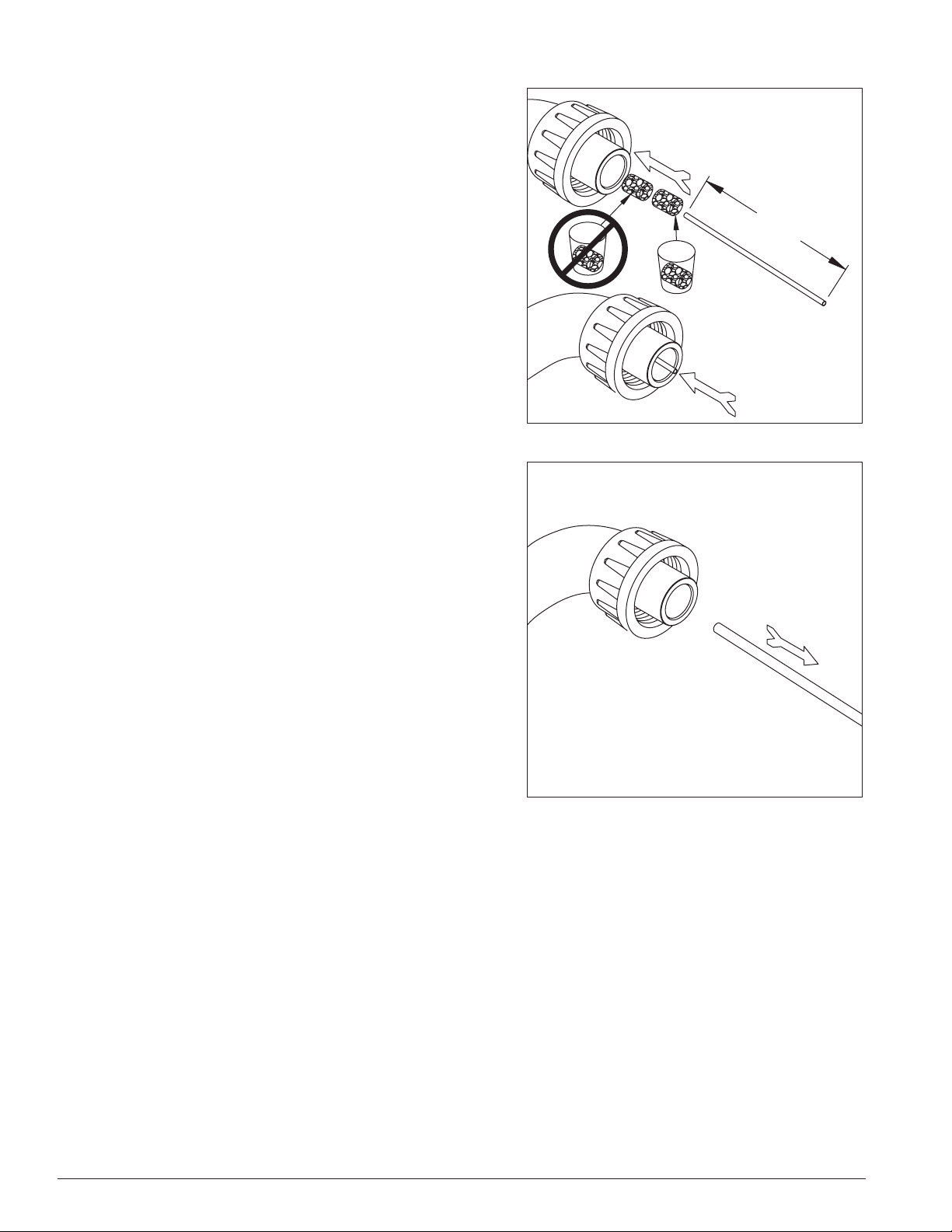
8. Using disposable food service grade gloves, insert dry
Sani-Sponge™ (kit part# 00132068). Next, insert SaniSponge soaked in Nu-Calgon IMS-II or IMS-III sanitizer
solution (from Step 5). Push both Sani-Sponges down ice
transport tube with supplied pusher tube(Fig.8).
Fig. 8
9. Remove and discard 16" (407mm) pusher tube (Fig. 9).
1
Fig. 9
16"
(407mm)
2
3
10 Horizon HCD700R/N, HMD700R/N Ice Machines
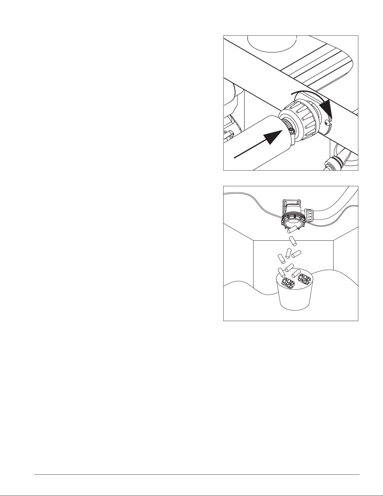
10. Reconnect coupling. When sanitizing cycle ends,
machine will start producing ice. Press power switch ON.
Ice pushes Sani-Sponges through tube (Fig. 10).
11. Place a sanitary (2 gallon or larger) container in bin or
dispenser to collect Sani-Sponges and ice for 10 minutes.
Collect 5.5 lbs (3kg) of ice from unit. Discard ice and
Sani-Sponges (Fig.11).
Fig. 10
Fig. 11
Horizon HCD700R/N, HMD700R/N Ice Machines 11

Service
Ice machine operation (all models)
Follett’s ice machine consists of ve distinct functional systems covered in detail as follows:
§ Water system
§ Electrical control system
§ Mechanical assembly
§ Refrigeration system
§ Bin full
The Horizon ice machine overview
The Follett Horizon ice machine uses a horizontal, cylindrical evaporator to freeze water on its inner surface. The
refrigeration cycle is continuous; there is no batch cycle. The evaporator is ooded with water and the level is
controlled by sensors in a reservoir. A rotating auger (13 RPM) continuously scrapes ice from the inner wall of the
evaporator. The auger moves harvested ice through the evaporator into an ice extrusion canal. The ice is forced
through a restrictive nozzle that squeezes out the water and creates the Chewblet. The continuous extrusion process
pushes the Chewblets through a transport tube into a dispenser or bin.
A solid state PC board controls and monitors the functionality of the ice machine. In addition to sequencing electrical
components, the board monitors various operational parameters. A full complement of indicator lights allows visual
status of the machine's operation. Additionally, the PC board controls the self-ushing feature of the ice machine. The
evaporator water is periodically drained and replenished to remove minerals and sediment.
A unique “bin full” detection system is incorporated in the Horizon ice machine. A switch located at the ice discharge
port of the machine detects the position of the transport tube. When the bin lls up with ice, the transport tube
moves out of the normal running position, and the switch turns the ice maker off. A domed housing at the end of the
transport tube contains the ice extrusion loads during shut down.
Harvest system diagram
Ice Transport Tube
Water Inlet
Compression
Nozzle
Auger
12 Horizon HCD700R/N, HMD700R/N Ice Machines
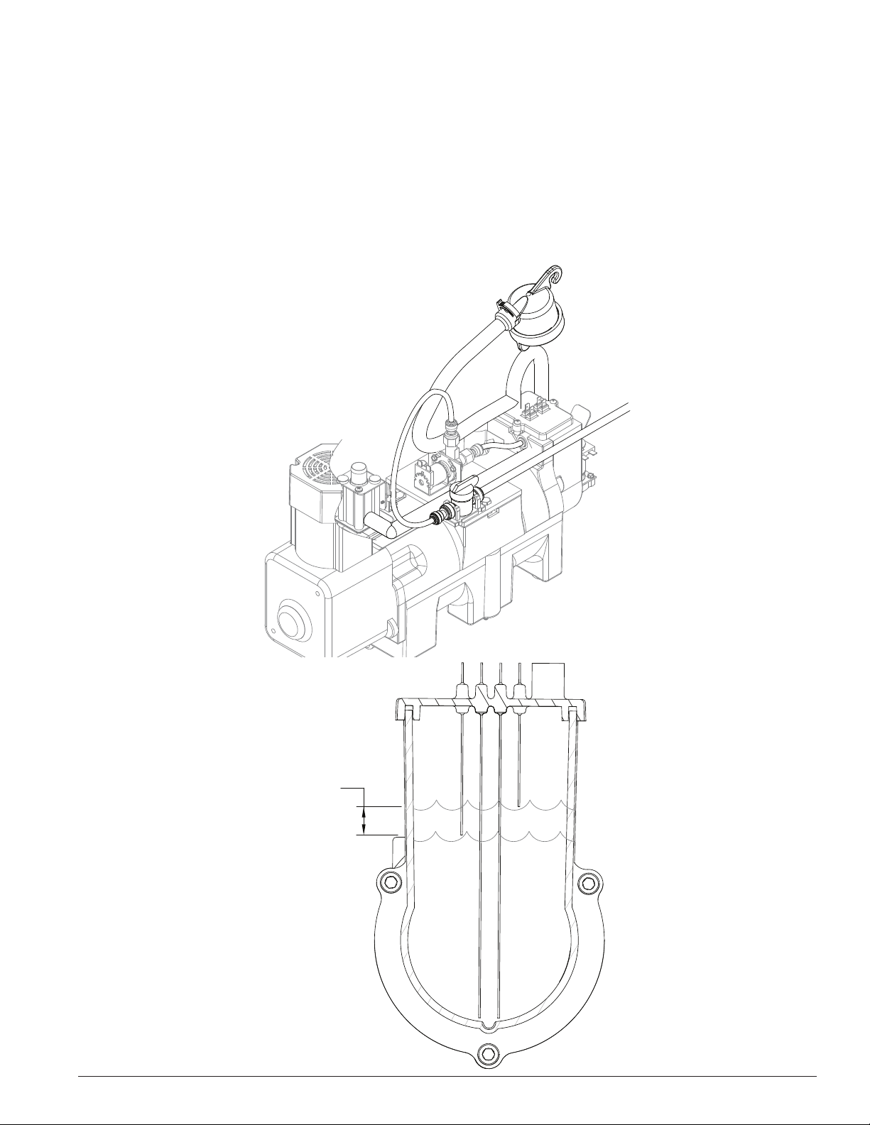
Water system
The water level in the evaporator is controlled by a feed solenoid and level detecting sensors. Referencing the
diagram below, water sensing rods extend down into the reservoir at the end of the evaporator assembly. The system
works via electrical conductivity as follows:
One of the longest probes is a common. When water is between any of the other probes and the common, the PC
board will sense the activation. During normal operation, the water level rises and falls between the Normal High and
Normal Low sensors. As water is consumed to make ice, the level will fall until the Normal Low sensor is exposed,
triggering the water feed solenoid on. Water will ll until the Normal High sensor is activated.
Note: The potable water dissolved solids content must be greater than 10 ppm for the water control system to
function properly. If using reverse osmosis water ltration system, ensure T.D.S level is greater than 10ppm.
Water system diagram
Water level diagram
NORMAL
OPERATING
RANGE
NORMAL LO
COMMON
NORMAL HI
ALARM LO
Horizon HCD700R/N, HMD700R/N Ice Machines 13
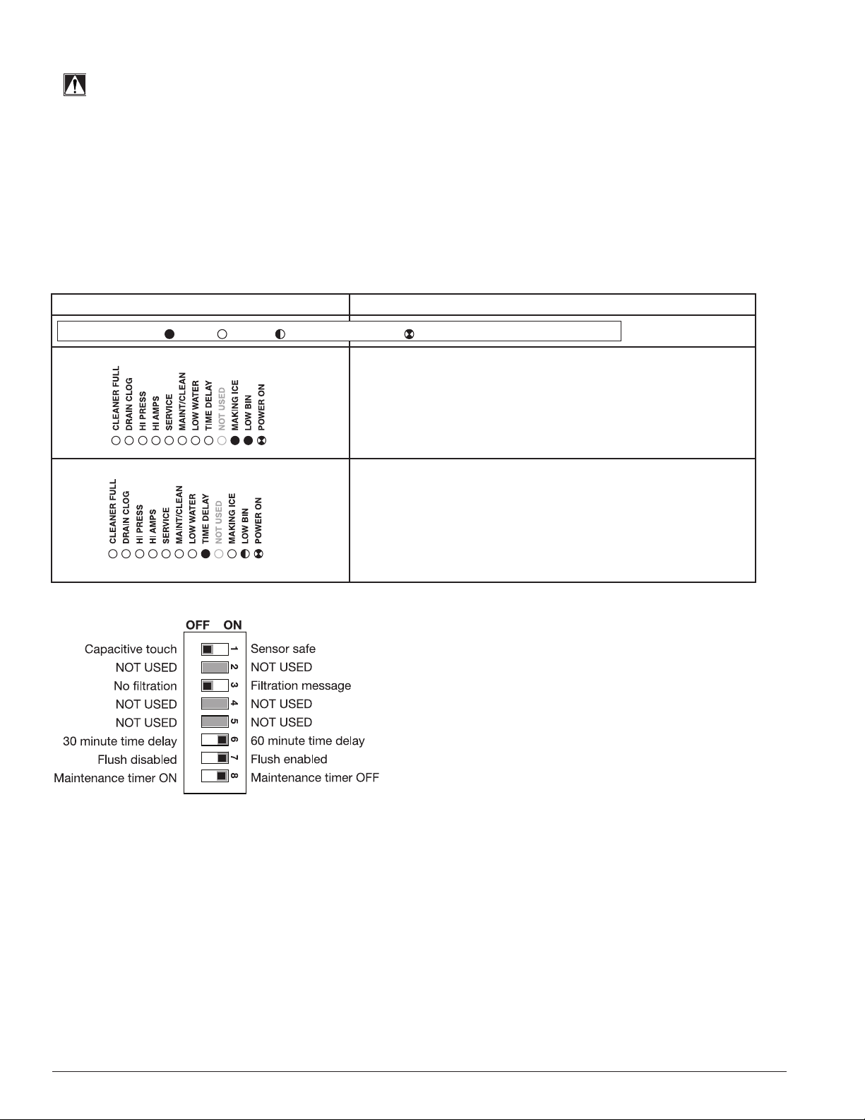
Electrical system
FLASHINGON or OFF
Legend:
OFFON
ATTENTION!
To prevent circuit breaker overload, wait 15 minutes before restarting
this unit.
Normal control board operation
The PC board indicator lights provide all the information necessary to determine the machine's status. Green indicator
lights generally represent “go” or normal operation; Yellow indicators represent normal off conditions; Red indicators
generally represent alarm conditions, some of which will lock the machine off.
A ashing green light labeled POWER indicates power to the machine. All other normal operation status indicators are
covered as follows:
Ice machine disposition Operating conditions
1. Ice machine is making ice.
.
2. Ice machine is not making ice.
DIP Switch Settings
1. Normal running.
2. Normal time delay. When the bin lls with ice, the LOW
BIN light goes out and the refrigeration and auger drive
systems immediately shut down. (Note: The fan motor
will continue to run for 10 minutes to cool condenser)
The TIME DELAY light comes on, initiating the time delay
period. When the time delay expires, the machine will
restart provided that the LOW BIN light is on.
14 Horizon HCD700R/N, HMD700R/N Ice Machines
 Loading...