

Follett E15CI100A Installation Manual
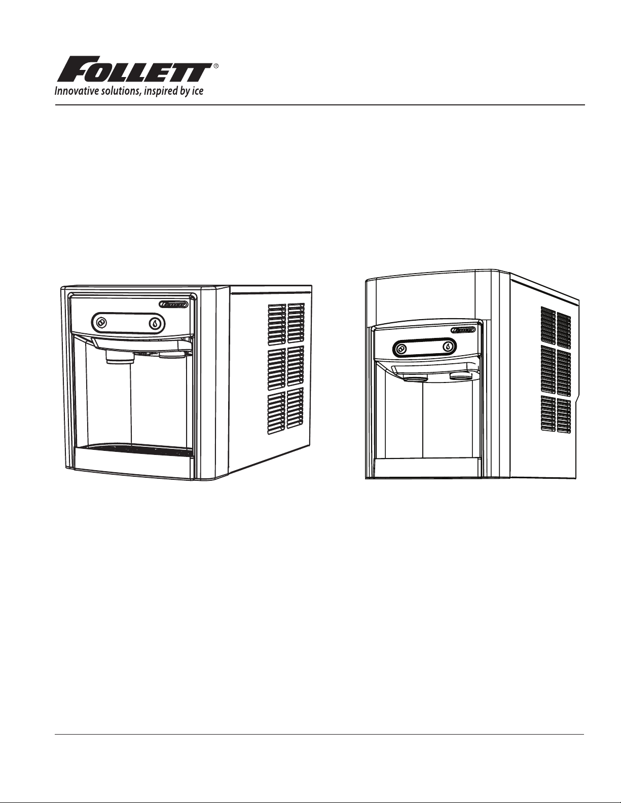
Countertop Ice Dispenser with
Chewblet® Ice Machine
E7CI100A, E15CI100A,
230 V/50 Hz, Rear Drain
Installation, Operation and Service Manual
E7CI100A
Following installation, please forward this manual
to the appropriate operations person.
801 Church Lane • Easton, PA 18040, USA
Toll free (877) 612-5086 • +1 (610) 252-7301
www.follettice.com
E15CI100A
Order parts online:
www.follettice.com
01103522R00

Contents
Welcome ...................................................................................... 3
Before You Begin ............................................................................... 3
Important Safety Information ..................................................................... 4
Specications ................................................................................. 4
Dimensions ................................................................................. 4
Ambient Information .......................................................................... 4
Plumbing ................................................................................... 4
Specications ................................................................................. 5
Water ..................................................................................... 5
Clearances ................................................................................. 5
Electrical ................................................................................... 5
Refrigeration ................................................................................ 5
Heat Rejection .............................................................................. 5
E7 Series Detailed Drawing .................................................................... 6
E15 Series Detailed Drawing ................................................................... 6
Installation .................................................................................... 7
Countertop Installation ........................................................................ 7
Maintenance/Cleaning Mode ..................................................................... 9
Accessing Internal Components .................................................................. 9
Cleaning and Sanitizing Procedure ................................................................10
Service ...................................................................................... 12
LED Indicator Description ..................................................................... 12
Evaporator Disassembly ...................................................................... 13
Evaporator Assembly ........................................................................ 16
Water Feed Schematic ....................................................................... 20
Storage Bin Melt Water/Evaporator Feed/Clean Out System Schematic ................................ 20
Vent System Schematic ...................................................................... 21
Refrigeration Schematic ...................................................................... 22
Condenser Fan Motor Removal (E7 Series Shown) ................................................ 23
User Interface Display Identication ............................................................. 24
Electrical Wiring Diagram ..................................................................... 25
Parts .......................................................................................26
E7 Series Exterior. . . . . . . . . . . . . . . . . . . . . . . . . . . . . . . . . . . . . . . . . . . . . . . . . . . . . . . . . . . . . . . . . . . . . . . . . . . 26
E7 Series Interior ........................................................................... 28
E15 Series Exterior .......................................................................... 30
E15 Series Interior .......................................................................... 32
E7 Series Bin Assembly ...................................................................... 34
E15 Series Storage Bin Assembly .............................................................. 36
Evaporator Assembly ........................................................................ 38
2 Dispenser and Ice Machine 230 V/50 Hz, Rear Drain
Welcome
Follett equipment enjoys a well-deserved reputation for excellent performance, long-term reliability, and outstanding
after-the-sale support. To ensure that this product delivers that same degree of service, we ask that you take a
moment to review this manual before beginning the installation. Should you have any questions or require technical
help at any point, please call our technical service group at (877) 612-5086 or +1 (610) 252-7301.
Before You Begin
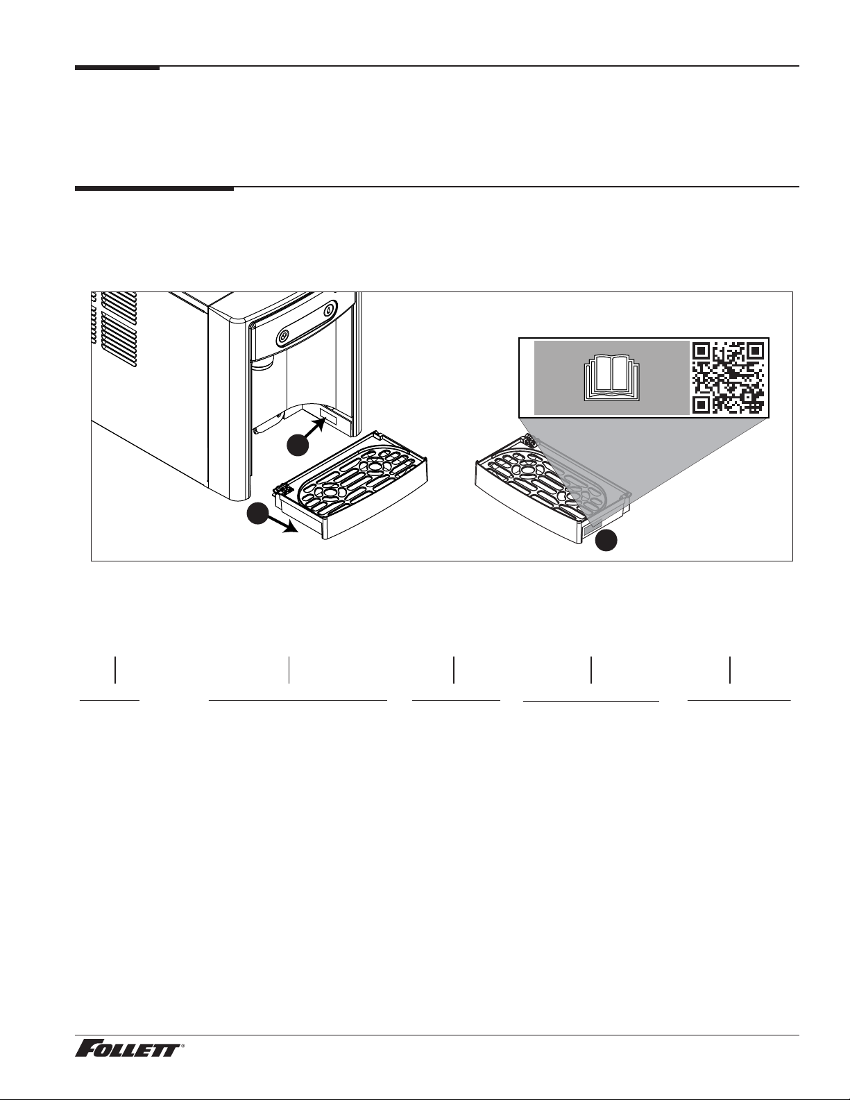
After uncrating and removing all packing material, inspect the equipment for concealed shipping damage. If damage
is found, immediately notify the shipper and contact Follett Corporation so that we can help in the ling of a claim,
if necessary. If needed, the serial number of your dispenser can be found by removing the drip tray ❶ and locating
the serial number label ❷. A QR Code is located on the right hand side of the drip tray ❸. This code allows you to
access manuals, technical bulletins, and on-line training related to the 7 Series and 15 Series dispensers.
Scan to access technical documentation
01105196R00
www.follettice.com/7SeriesTechDocs
2
1
3
Check your paperwork to verify that you received the correct dispenser. Follett conguration numbers are designed
to provide information about the type of dispenser you are receiving. The following is an explanation of the different
model numbers.
E 7 CI 100 A
Electrical
E 230 V/50 Hz
Dispenser Storage Capacity
7 7 lb (3.1 kg)
15 15 lb (6.8 kg)
Conguration
CI Countertop
Ice Machine Capacity
100 lb (45.3 kg) per day
Condenser Type
A Air-cooled
Dispenser and Ice Machine 230 V/50 Hz, Rear Drain 3
Important Safety Information
Please read and adhere to the following safety information while installing, using, or servicing your Follett Ice
Dispenser.
1. Always disconnect power before servicing the dispenser.
2. Ice is slippery. Maintain counters and oors around dispenser in a clean and ice-free condition.
3. Ice is food. Follow the recommended cleaning and sanitizing instructions to maintain cleanliness of
delivered ice.
4. The appliance is not intended for use by persons including children with reduced physical, sensory or
mental capabilities, or lack of experience and knowledge, unless they have been given supervised or
instruction concerning use of the appliance by a responsible person for their safety. Children should be
supervised to ensure that they do not play with the appliance.
5. The appliance is only to be installed in locations where its use and maintenance is restricted to trained
personnel.
6. The appliance is not suitable for installation in an area where a water jet could be used.
Specications
Dimensions
E7CI100A E15CI100A
Width 40 cm (14.50") 40 cm (14.50")
Depth 56.2 cm (22.12") 59.7 cm (23.50")
Height 44.5 cm (17.50") 57.2 cm (22.50")
Unit Shipping Weight 41 kg (90 lb) 45.4 kg (100 lb)
Ambient Information
CAUTION!
The E7CI100A, E7FS100A and E15CI100A, E15FS100A are for indoor use only. Designed for commercial
use. Follett is not able to provide in-house services for residential installations.
Maximum* Minimum*
Air Temperature
Water Temperature 32.2 C (90 F) 4.5 C (40 F)
Water Pressure 483 kpa (70 psi) 69 kpa (10 psi)
Relative Humidity 55% at 25.5 C (78 F)
* Use outside of these limitations is misuse and will void warranty.
† Best performance is achieved between 27 C (80 F) and 10 C (50 F).
†
38 C (100 F) 10 C (50 F)
Plumbing
§ Water Inlet: 1/4" MPT
§ 1/2" bin drain line must slope 1/4" per foot (6 mm per 30,4 cm run).
§ Optional Drain Accessory Kit (item# 00956375 or 00981977): 1/2" ID tubing
§ Water shut-off recommended within 1.5 m (5 ft.) of dispenser
4 Dispenser and Ice Machine 230 V/50 Hz, Rear Drain
Specications
Water
WARNING!
— Connect to potable water supply only.
— The discharge drain must be installed via a type AA, AB, or AD air gap or in accordance with
requirements of EN1717..
§ Water Mineral Content:
– TDS: greater than 5 ppm (mg/l) but less than 400 ppm (mg/l)
– Hardness: Less than 200 mg/l (12 gpg)
§ Not recommended for use with softened water
§ Ingress Protection (IP) rating: IPX0 (no protection)
Clearances
§ 7.62 cm (3") behind and on each side of dispenser for electrical connection and ventilation
Electrical
§ E Series: 230 V, 50 Hz, 1 phase, 5A, maximum fuse 10A
§ Connect to dedicated 10A circuit, fuse or breaker.
§ Must be grounded - requires 3-prong outlet. Do not remove ground.
§ Replacement cord instructions, type IEC 60320-C13 attachment - If the supply cord is damaged, it must be
replaced by a special cord or assembly available from the manufacturer or its service agent.
Refrigeration
WARNING!
Do not damage the refrigerant circuit. Refrigerant can cause personal injury and/or damage dispenser.
§ Refrigerant R134a – 204 grams (7.2 ounces)
Heat Rejection
§ 498 W (1700 BTU/hr)
Dispenser and Ice Machine 230 V/50 Hz, Rear Drain 5
Specications (continued)
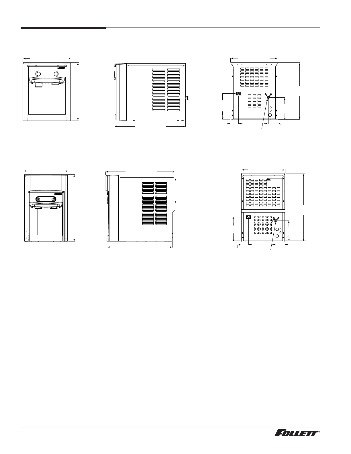
E7 Series Detailed Drawing
Countertop models
37.1 cm (14.62")
37.1 cm (14.62")
44.7 cm
(17.59")
E15 Series Detailed Drawing
Countertop models
37.1 cm (14.62")
57.2 cm
(22.50")
56.2 cm (22.12")
59.7 cm (23.50")
56.2 cm (22.12")
20.3 cm
(8.00")
6.04 cm
(2.38")
20.3 cm
(8.00")
6.04 cm
(2.38")
1/4" MPT
water inlet
37.1 cm (14.62")
1/4" MPT
water inlet
17.5 cm
(6.88")
7.62 cm
(3.00")
17.5 cm
(6.88")
7.62 cm
(3.00")
44.7 cm
(17.59")
57.2 cm
(22.50")
6 Dispenser and Ice Machine 230 V/50 Hz, Rear Drain
Installation
CAUTION!
No service or maintenance should be performed until the technician has thoroughly read this service
manual. Except for routine cleaning and sanitizing, only qualied technicians should attempt to service
or maintain this equipment.
Countertop Installation
The E7 Series countertop model is designed to t on counters underneath
standard mounted cabinets, this does not apply to E15 Series models. See
page 4 for dimensions. Installation instructions for freestanding model
may be found on page 9.
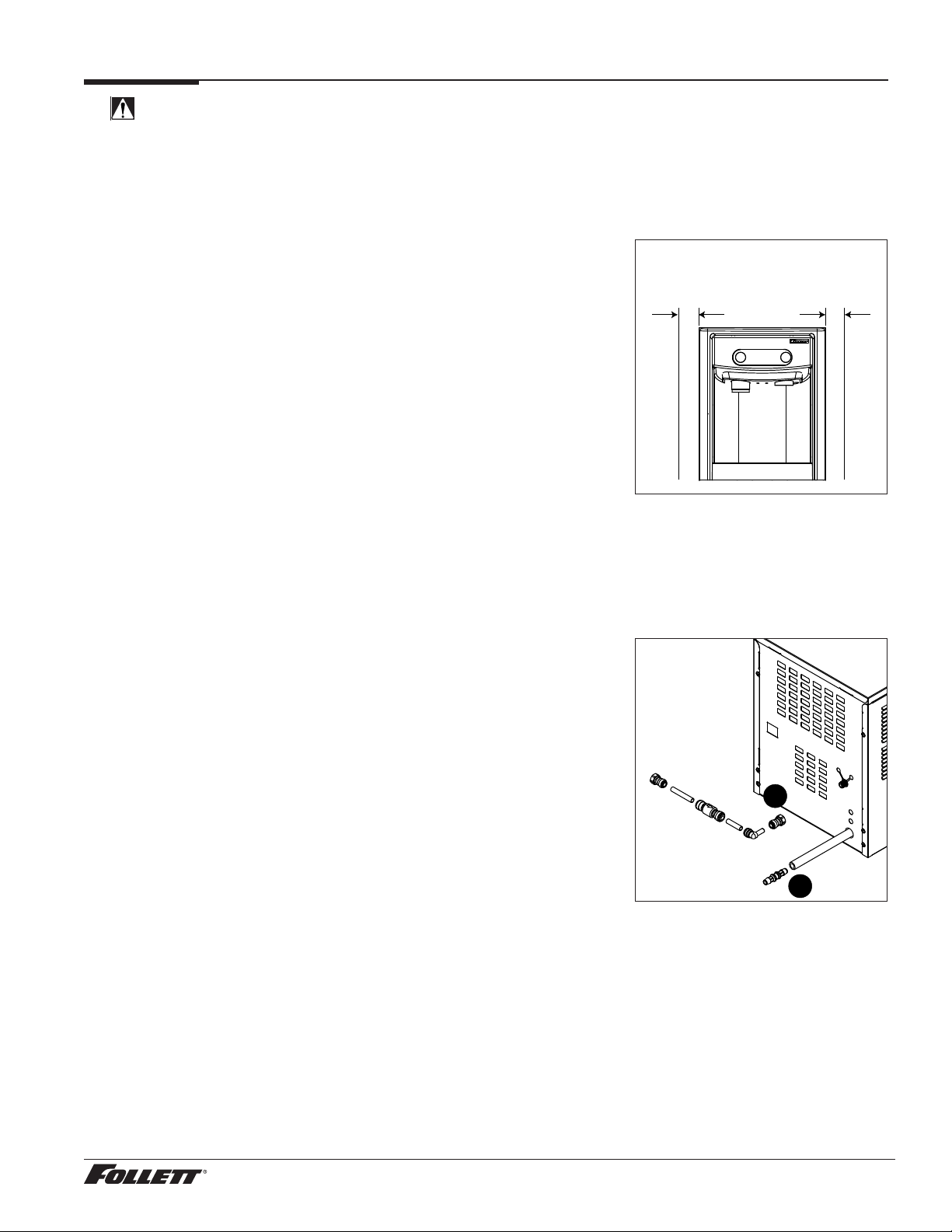
1. A clearance of at least 7.62 cm (3") is required behind and on
each side of the dispenser for electrical connection and ventilation
(Fig.1).
2. Rough-in the electrical service and water line.
§ Electrical: 230V, single phase. The dispenser is provided with a 2.4m
(8 ft.) power cord with choice of CEE 7/7, AS 3112, or BS1363 plug.
§ Water: supply line (with shut-off valve) connects to the dispenser's
1/4"MPT inlet.
NOTICE!
If installing optional Drip Tray Drain Kit or Leg Accessory,
complete those steps before proceeding. Refer to instructions
included with the Drip Tray Drain Kit, or see page 8 for Leg
Accessory instructions.
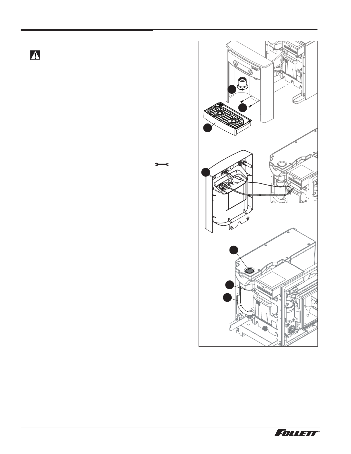
3. Connect water line (Fig. 2.1).
4. Connect to the 1/2" ID drain line (Fig. 2.2) (barb tting provided) and
route to customer drain. Drain line must slope 6 mm per 30,4 mm run
(1/4" per foot).
5. Connect power supply.
6. Sanitize the dispenser prior to use (see Page 10).
Fig. 1
Fig. 2
countertop models
minimum 77 mm (3")
clearance required
1
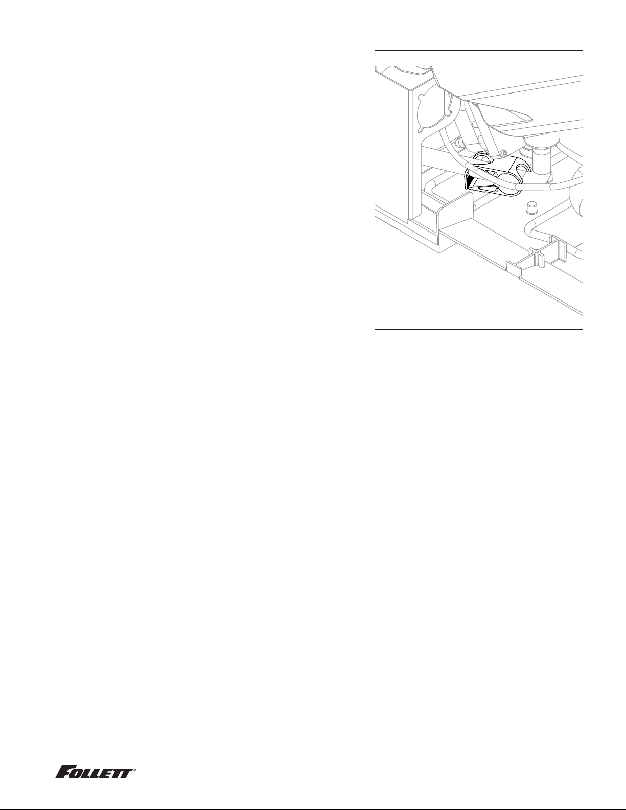
Check valve must
be installed as
shown for proper
operation - note
direction of arrow.
2
Dispenser and Ice Machine 230 V/50 Hz, Rear Drain 7
Installation (continued)
Optional Leg Accessory Installation
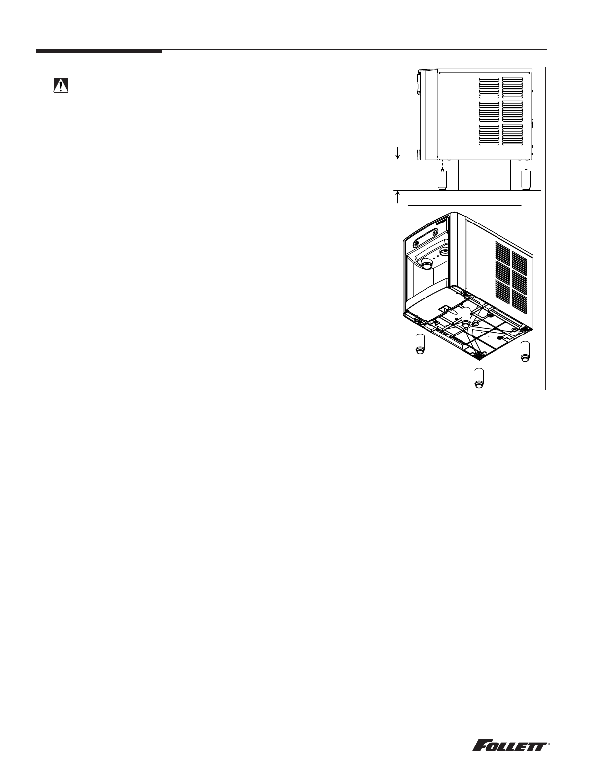
CAUTION!
Use caution when tipping the dispenser during leg installation. Do
not lay unit on back or side. DO NOT EXCEED 30° angle. Tipping
more than 30° can result in compressor malfunction.
1. If installing optional 4" Leg Accessory (item# 00956300), place a
12.7 cm (5") spacer underneath the dispenser to ease installation.
2. Remove four plastic, thread-protecting plugs from bottom of
dispenser.
3. Screw each leg into chassis (Fig. 3).
Fig. 3
12.7 cm (5")
min.
spacer
8 Dispenser and Ice Machine 230 V/50 Hz, Rear Drain
Maintenance/Cleaning Mode
Cleaning Mode (Dispensing Disabled) - Use when cleaning surface
Entering Cleaning Mode disables the User Interface and allows you to clean
the outside of the dispenser without accidentally dispensing ice.
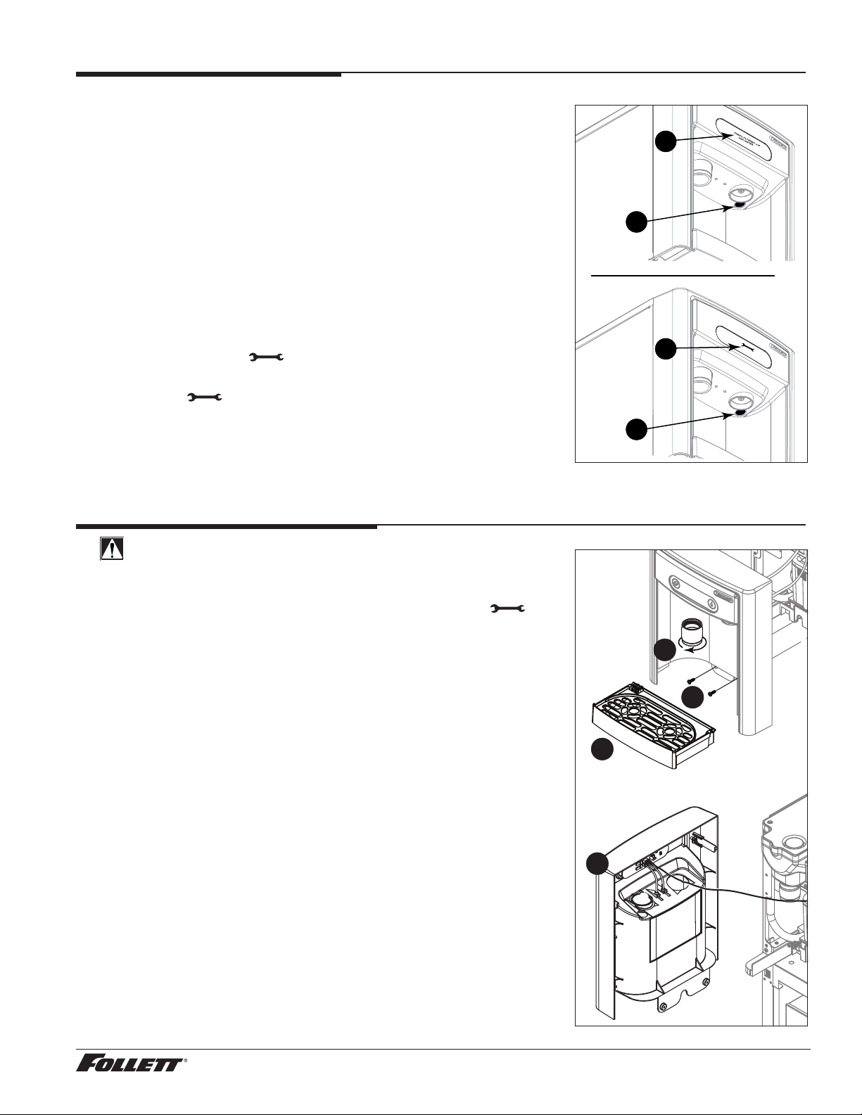
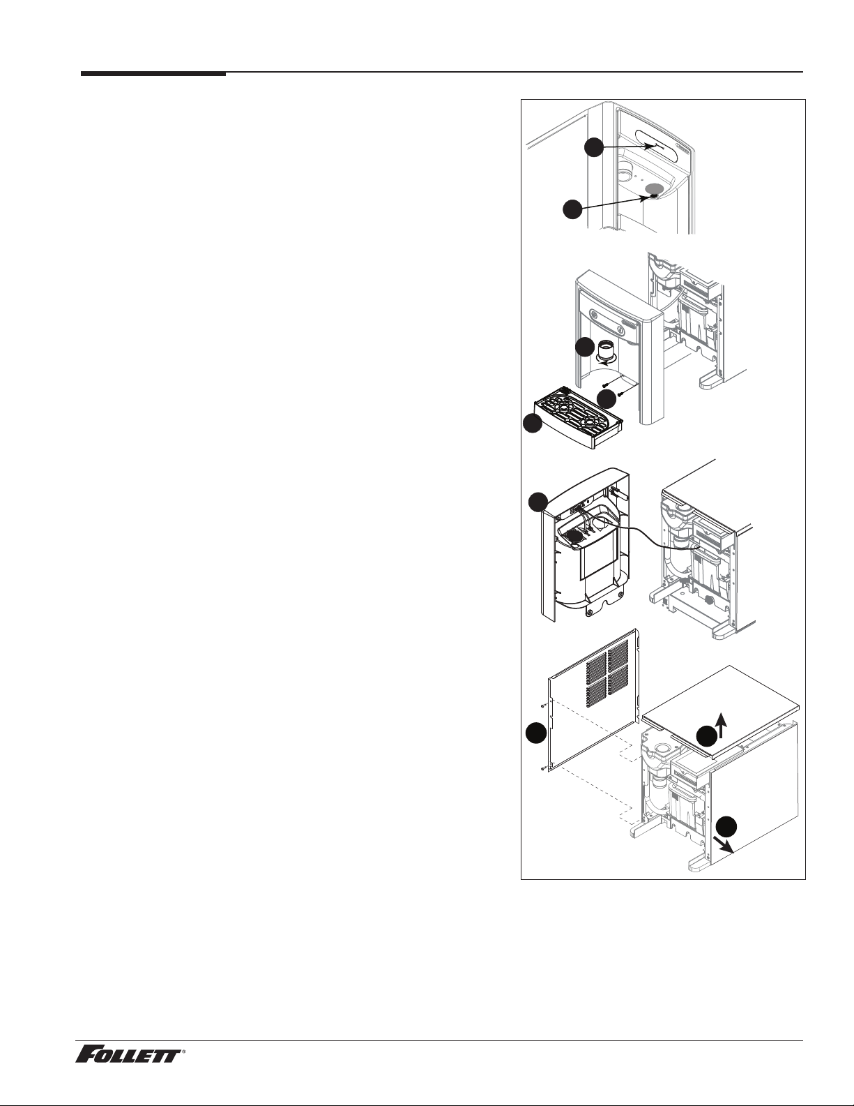
1. To enter Cleaning Mode, press and immediately release the
maintenance/clean switch (Fig. 4.1) so that only "ICE" displays in
the user interface (Fig.4.2).
2. To exit Cleaning Mode, press and immediately release the
maintenance/clean switch so that the ice icon also displays in the
user interface.
Maintenance Mode (All Operations Disabled) - Use when cleaning ice
machine
Entering Maintenance Mode disables all operations and allows you to safely
clean and/or sanitize the icemaker and dispenser.
1. To enter Maintenance Mode, press and hold the maintenance/clean
switch (Fig. 4.3) until displays in the user interface (Fig.4.4).
2. To exit Maintenance Mode, press and hold the maintenance/clean
switch until no longer displays in the user interface.
Note: Entering and exiting Maintenance Mode will reset the six-month
periodic maintenance reminder.
Fig. 4
2
1
4
3
Accessing Internal Components
CAUTION!
Except for routine cleaning and sanitizing, only qualied
technicians should attempt to service or maintain this equipment.
1. Press and hold the maintenance/clean switch (Fig. 4.1) until
displays in the user interface (Fig. 4.2).
2. Remove (unscrew) chrome ice dispenser chute (Fig. 5.1).
3. Remove the drip tray (Fig. 5.2).
4. Remove the two screws (Fig. 5.3) on the front panel (behind the
drip tray).
5. Remove and set aside the front panel (Fig. 5.4) - do not
disengage the plug on the back of the User Interface.
Fig. 5
1
3
2
4
Dispenser and Ice Machine 230 V/50 Hz, Rear Drain 9
Cleaning and Sanitizing Procedure
Cleaning and sanitizing should be performed at least every 6
months (more often if local water conditions dictate).
WARNING!
§ Place the dispenser in Maintenance Mode prior
to servicing or cleaning the ice machine. See
Maintenance/Cleaning Mode on page 9.
§ For protection, rubber gloves and safety goggles
(and/or face shield) should be worn when handling
SafeCLEAN Plus™.
§ Do not use bleach, it will damage the dispenser.
Required Supplies
§ E7 Series: 0.621 L (21 oz.) or 3 packets SafeCLEAN Plus
E15 Series: 1.24 L (42 oz.) or 6 packets SafeCLEAN Plus
§ Funnel, bucket, 38 C (100 F) potable water
Ice machine and Dispenser
1. Dispense all the ice out of the unit.
2. Press and hold maintenance/clean switch until
displays in the user interface to enter Maintenance Mode.
3. Remove (unscrew) chrome ice dispense chute (Fig. 6.1).
4. Remove drip tray (Fig. 6.2).
5. Remove (2) screws located behind the drip tray (Fig. 6.3).
6. Move front panel and place on top or beside unit (Fig. 6.4).
7. Remove plug cap from the end of water reservoir drain
tube (Fig. 14.5) and lower tube to drain water into bucket.
After the system has been drained of water replace plug
cap in water reservoir drain tube.
8. Secure tube in holder.
9. Remove cap from storage bin lid cover (Fig. 6.6).
10. Screw storage bin lid cover cap onto ice discharge chute
(Fig. 6.7).
Fig. 6
1
3
2
4
6
10 Dispenser and Ice Machine 230 V/50 Hz, Rear Drain
7
5
11. Locate the storage bin drain tube pinch clamp (Fig. 7) and
engage (close).
12. E7 Series: Mix 0.621 L (21 oz.) or 3 packets SafeCLEAN
Plus with 11.4 L (3gallons) of 38 C (100 F) potable water.
E15 Series: Mix 1.24 L (42 oz.) or 6 packets SafeCLEAN
Plus with 22.7 L (6gallons) of 38 C (100 F) potable water.
13. Pour cleaning solution into bin lid access spout until
solution reaches and remains level at the spout neck.
(Because the cleaning solution reaches the internal
components via overow into the ice transport tube, it is
necessary to add cleaning solution until it remains level at
the spout neck.)
14. Allow the solution to remain in unit for 15 minutes.
15. While machine is cleaning, remove top and right side
panel to access and clean air-cooled condenser.
16. Submerge ice dispense chute in the remainder of solution
for 2 minutes. Rinse with clean, potable water.
1 7. Drain system: (1) release (open) the storage bin drain tube
pinch clamp and (2) lower water reservoir drain tube into
bucket.
18. Secure capped water reservoir drain tube into holder and
engage (close) storage bin drain tube pinch clamp.
19. Fill and drain three times with potable water. Secure water
reservoir drain tube and release (open) the storage bin
drain tube pinch clamp.
20. Place a bucket under the dispense chute and remove cap.
Note: Some solution will remain and drain out when cap is
removed. Reposition cap on bin lid spout.
2 1. Reinstall front panel, ice dispense chute, and drip tray.
22. Press and hold maintenance/clean switch to exit
Maintenance Mode.
Fig. 7
Dispenser and Ice Machine 230 V/50 Hz, Rear Drain 11
Cleaning and Sanitizing Procedure (continued)
User Interface and Exterior Cabinet
1. Press and release maintenance/clean switch so that only "ICE" displays in the user interface to enter
Cleaning Mode (and disable dispensing).
2. Plastic parts, including the user interface, can be cleaned with a non-abrasive glass cleaner. Clean
stainless steel panels with stainless steel cleaner.
3. Press and release maintenance/clean switch to put unit back into service.
Service
LED Indicator Description
The LED Indicator is located behind the front panel.
Fig. 8
Clean
LED Name LED Color Description
Clean Green The dispenser is in Cleaning Mode. Dispenser is disabled to allow for cleaning of front panel.
— N/A Not used.
PM Red Six-month periodic maintenance required.
Drip tray Red Drip tray full.
Water leak Red Internal leak in dispenser.
High amps Red Auger gearmotor has exceeded 0.55A. The HI amps and Time delay LEDs will illuminate,
Service Red 8000 hour bushing check (call Follett technical service group at (877) 612-5086 or
Maintenance Yellow Enter Maintenance Mode by pressing and holding maintenance/clean switch for 5 seconds.
Low water Yellow Insufficient water supply to machine or no low bin LED upon startup.
Time delay Yellow Ice production will not resume for at least 15 minutes after a full bin is achieved and a
Sleep cycle Green After a full bin and 10 minutes of non-use, the unit goes into standby and will not produce ice
Making ice Green Gearmotor, compressor, and fan motor energized.
Low bin Green Bin switch closed calling for ice.
Power on Green Power supplied to unit.
PM
Drip tray
Water leak
HI press
HI amps
Service
Maint
Low water
Time delay
Sleep cycle
Making ice
Low bin
Power ON
See Maintenance/Cleaning Mode on page 9.
the machine will shut down for one hour, the LEDs will turn off, and the machine will resume
normal operation.
+1 (610) 252-7301).
Unit will not make or dispense ice.
minimum amount of dispense activity has elapsed.
until either:
E7 Series:12 hours has elapsed, E15 Series: 4 hours has elapsed
or ice has dispensed.
12 Dispenser and Ice Machine 230 V/50 Hz, Rear Drain
Service (continued)
Evaporator Disassembly
1. Disconnect power from the dispenser.
2. Turn off water supply to dispenser.
3. Remove (unscrew) chrome ice dispenser chute (Fig.9.1).
4. Remove the drip tray (Fig. 9.2).
5. Remove the two screws (Fig. 9.3) on the front panel
(behind the drip tray).
6. Remove and set aside the front panel (Fig. 9.4) - do not
disengage the plug on the back of the User Interface.
7. Lift and remove the top panel, set aside (Fig.16.5).
8. Remove two screws (Fig. 9.6) and remove left side panel.
9. Remove two screws (Fig. 9.7) and remove right side
panel.
Fig. 9
2
1
1
3
2
4
6
5
7
Dispenser and Ice Machine 230 V/50 Hz, Rear Drain 13
Service (continued)
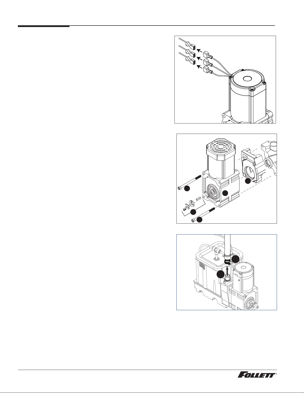
10. Unplug the gear motor (three connectors) (Fig.10).
11. Remove ground screw connection.
12. Remove gear motor:
§ Remove M6 allen screw, retainer, spacer and key (Fig. 11.1).
§ Remove two M6x90 allen screws (Fig. 11.2).
§ Pull gear motor from auger (Fig. 11.3).
§ Remove main housing insulation (Fig. 11.4).
13. Remove all traces of petro-gel from auger shaft.
Fig. 10
Fig. 11
14. Remove compression nozzle:
§ Loosen hose clamp (Fig.12.1).
§ Remove transport tube (Fig. 12.2).
4
2
3
1
2
Fig. 12
1
2
14 Dispenser and Ice Machine 230 V/50 Hz, Rear Drain
 Loading...