

Page 1
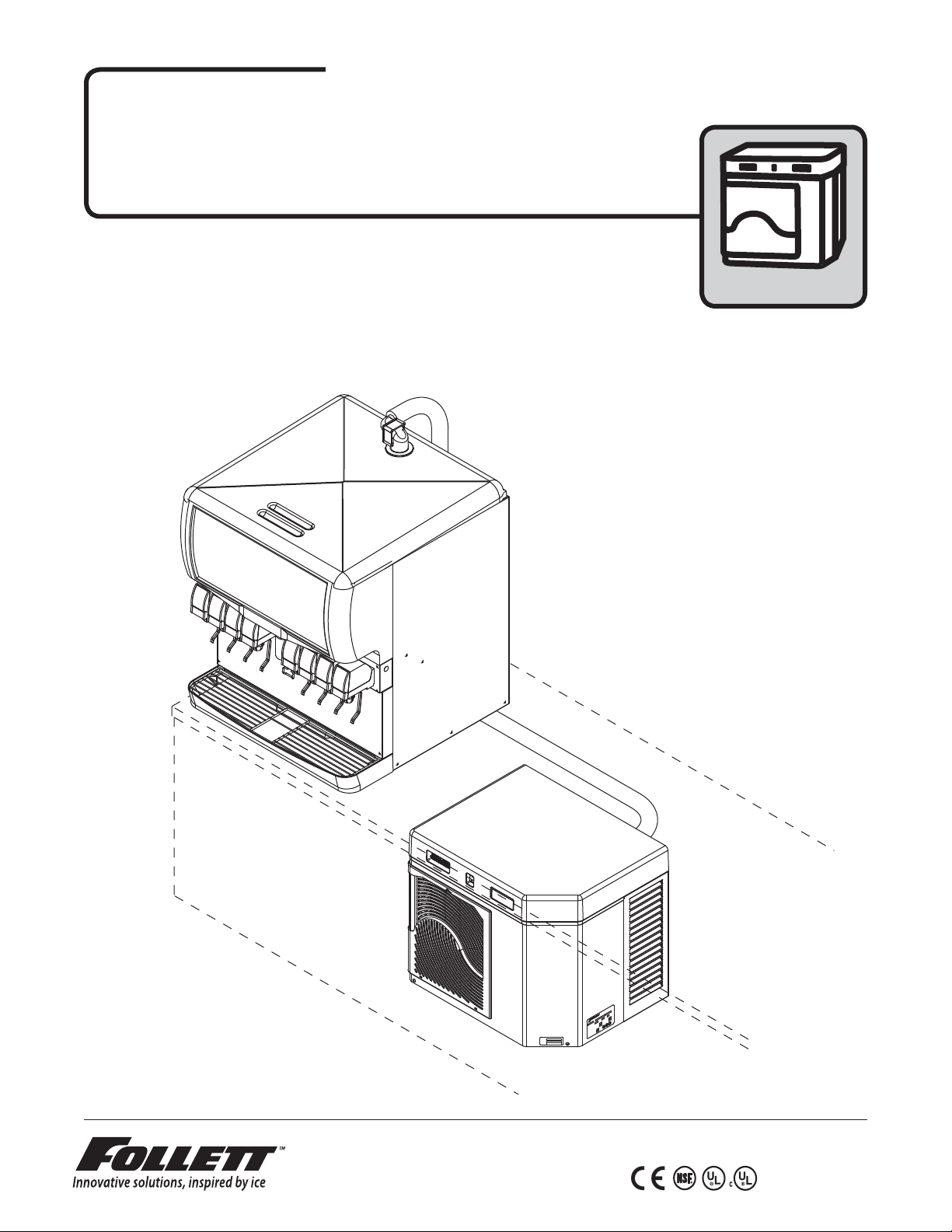
Horizon™ Icemaker Installation Instructions
U
L
L
U
R
C
R
for Harmony™ Satellite- ll™ Applications
HCC/HMC/HCE/HME1000AHS, HCC/HMC/HCE/HME1400AHS,
HCC/HMC/HCE/HME1000WHS, HCC/HMC/HCE/HME1400WHS
(See model number con gurator on page 2 for details.)
Order parts online
www.follettice.com
Horizon Satellite- ll icemakers
t most countertop dispensers manufactured by
Cornelius • Lancer • SerVend
self-contained
208264
Stock Module Identification Plate
Module No.
Product
Service No.
801 Church Lane • Easton, PA 18040, USA
Toll free (877) 612-5086 • +1 (610) 252-7301
www.follettice.com
a
i
n
a
v
yl
s
enn
P
O
n
N
o
t
s
RT
E
a
L
A
E
P
NG
I
S
E
S
A
H
P
Z
Z
O
H
N
NO
O
I
T
AL
I
A
SIG
R
R
P
E
O
S
P
E
R
D
G
E
O
R
T
C
S
A
C
T
E
L
H
T
C
O
O
V
N
R
I
P
E
E
D
D
Y
A
I
L
A
S
M
S
L
U
A
E
W
H
L
M
O
T
E
R
L
F
E
D
S
O
TH
N
M
R
O
S
S
E
S
R
P
P
M
M
A
D
CO
A
R
O
L
TO
O
LL
M
FU
S
P
M
E
T
A
D
I
S
RAN
H
E
S
G
G
I
P
I
R
H
M
F
A
E
E
R
R
U
S
S
E
R
P
Y
T
N
CI
A
G
P
I
S
M
A
E
T
I
D
CU
E
R
Z
CI
SI
H
E
S
C
U
N
F
A
T
R
I
B
U
.
C
N
I
R
I
M
C
CH
N
A
R
B
.
X
A
M
00159897R05
Page 2
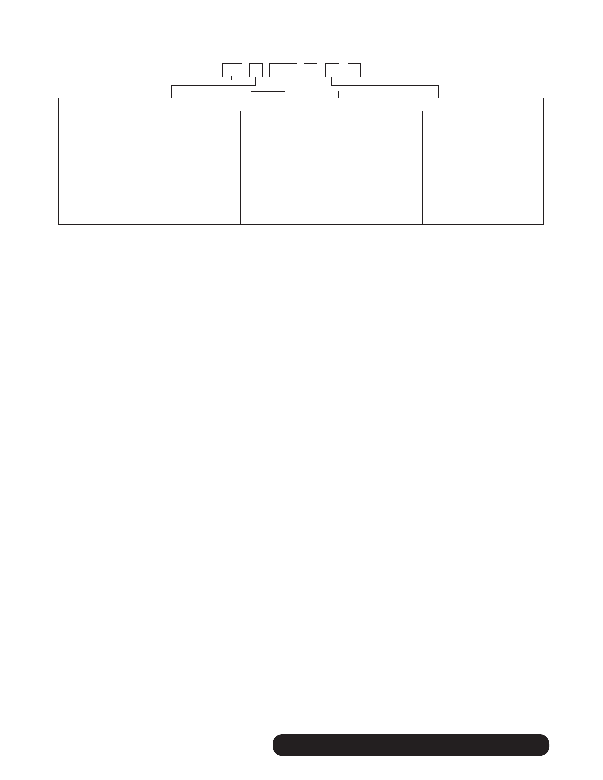
Chewblet® Ice Icemaker Model Number Configurations
A V SC 1400HC
Icemaker Voltage Series Condenser
MC Maestro
Chewblet
(400 Series)
HC Horizon
Chewblet
(1000, 1400,
1650 Series)
HM Horizon
Micro
Chewblet
C 208-230/60/1 (icemaking head)
Self-contained only.
D 115/60/1 (icemaking head)
Self-contained and remote.
If remote unit, high side is
208-230/60/1.
E 230/50/1 (icemaking head)
Self-contained only.
F 115/60/1 (icemaking head)
Remote only. High side is
208-230/60/3.
400 up to
454 lbs
(206kg)
1000 up to
1036 lbs
(471kg)
1400 up to
1450 lbs
(658kg)
1650 up to
1580 lbs
(717kg)
A Air-cooled, self-contained
W Water-cooled, self-contained
R Air-cooled, remote condensing unit
N Air-cooled, no condensing unit for
connection to parallel rack system
Application Configuration
V Vision™
H Harmony™
B Ice storage
bin
J Drop-in
M Ice Manager™
diverter valve
system
S Satellite-fill™
T Top-mount
2
self-contained HARMONY • SATELLITE-FILL
Page 3
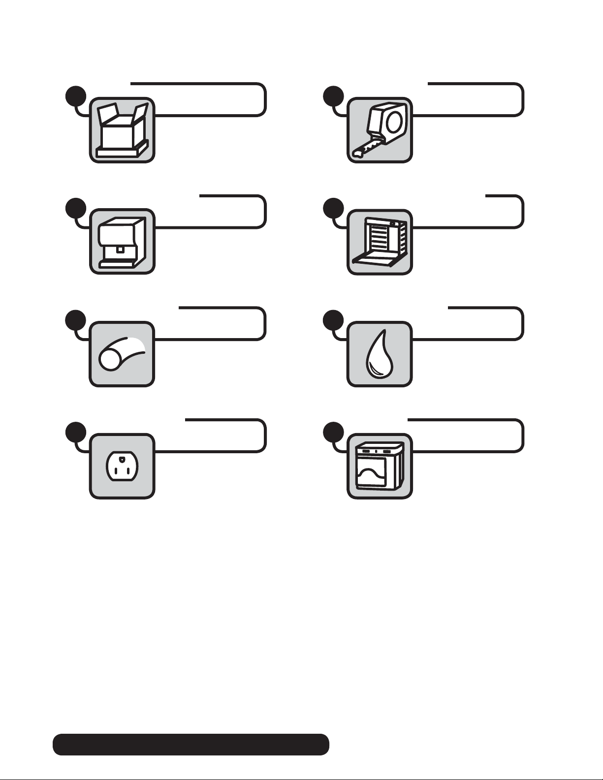
Read and complete the following 8 installation steps
Unpack
1
Dispenser preparation
3
Ice transport tube
5
Site preparation
2
Louvered docking assembly
4
External connection
6
Internal connection
7
Front cover
8
HARMONY • SATELLITE-FILL self-contained
3
Page 4
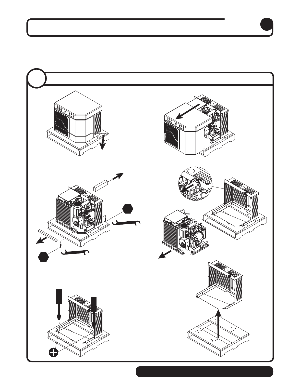
Carefully unpack and inspect the contents of your Follett icemaker.
1/2"
1/2"
➊➋
➌➍
➎➏
Unpack
1
1. 1
Unpack icemaker
4
self-contained HARMONY • SATELLITE-FILL
Page 5

Prepare the installation site.
Provide drainage, water supply and electrical power to within 6 feet
(2m) of icemaker in accordance with local and national codes. Outdoor
installation is not recommended and will void warranty.
Site preparation
2
2.1
2.1
Installation site requirements
1/4"
1'
➍
➊
➋
➌
➍
H_E1000A/W
requires 15 amp circuit
1.50 mm
H_E1400A/W
requires 20 amp circuit
4.00 mm
2
wire
2
wire
H_C1000A/W
NEMA
6-15
H_C1400A/W
NEMA
6-20
‡
‡
Electrical
➊
• H_C1000(A/W)HS 208-230/60/1-15 amps • H_C1400(A/W)HS 208-230/60/1-20 amps
• H_E1000(A/W)HS 230/50/1-15 amps
(H_E1000A/W Requires 15 amp circuit 1.50 mm2 wire) (H_E1400A/W Requires 20 amp circuit 4.00 mm2 wire)
‡ Plug must be provided by end user & must conform to standard EN 60 335-2-24 of the end destination.
Potable water supply
➋
‡
• H_E1400(A/W)HS 230/50/1-20 amps
• 10-70 psi (69-483kpa)
• 45 to 90 F (7 to 32 C)
• Follett recommends the use of an in-line water ltration system (item# 00130286)
Condenser water supply for water-cooled systems
➌
• 10 psi min.; 150 psi max. (69kpa min.; 1034kpa max.)
• 45 to 90 F (7 to 32 C)
• 1.5 gallons per minute (5.68 liters per minute)
Drain
➍
• The drain line from the icemaker must have at least 1/4" per foot pitch (6,4mm/0,3m)
HARMONY • SATELLITE-FILL self-contained
‡
5
Page 6

Prepare the dispenser.
Dispenser preparation
3
3.1
• Locate hole position 5" (127mm) from
• Cut 3" (77,2mm) diameter hole in
Top preparation
5"
(127mm)
3" ∅
(76,2mm)
back of dispenser top
dispenser top
3.2
• Remove protective tape from gaskets
Top preparation
3.3
Top preparation
➋
➊
➊
• Apply gaskets
• Install shuttle actuator
dispenser top and secure with locking nut
➊
through
➋
➌
➌
3.4
• Screw 4" (102mm) extension
Top preparation
bottom of shuttle actuator
➋
➊
➊
into
➋
6
self-contained HARMONY • SATELLITE-FILL
Page 7

3.5
Agitation adjust. – CORNELIUS
ON
OFF
Cornelius models ED, DB, DF, IDC and
FLAVOR FUSION
Adjust the agitation timer located on the
Cornelius PC board to 1 second on, 1 hour
off. Note: See Cornelius manual for more
information.
3.6
PRESS IN ON
THIS SIDE TO
TURN SWITCH
OFF.
SWITCH
OFF
Agitation adjustments – LANCER 4500 SERIES
ROCKER
SWITCHES
(VIEW LOOKING
DOWN)
OFF
SIDE VIEW
SIDE VIEW
1
2
3
4
5
6
7
8
PRESS IN ON
THIS SIDE TO
TURN SWITCH
ON.
SWITCH
ON
SWITCH
NUMBER
3
4
SWITCH
NUMBER
5
6
7
8
AGITATION TIME
1 SECOND
OOOXXOX
AGITATION FREQUENCY
NO A
O
O
O
O
O
O
X
O
2 SECONDS
3 SECONDS
ATION
GIT
10 MINUTES
O
O
X
O
4 SECONDS
X
20 MINUTES
30 MINUTES
O
O
O
X
X
O
X
O
40 MINUTES
50 MINUTES
O
O
X
X
O
X
X
O
X = ON
O = OFF
60 MINUTES
70 MINUTES
X
O
O
X
O
X
O
X
80 MINUTES
90 MINUTES
100 MINUTES
X
X
O
O
O
X
X
O
110 MINUTES
X
X
O
X
X
O
X
O
130 MINUTES
120 MINUTES
X
X
X
X
O
X
X
O
Lancer 4500 series only
Adjust the agitation time to 1 second, and the agitation frequency to 150 minutes. See Lancer
manual for more information.
140 MINUTES
150 MINUTES
X
X
X
X
HARMONY • SATELLITE-FILL self-contained
7
Page 8
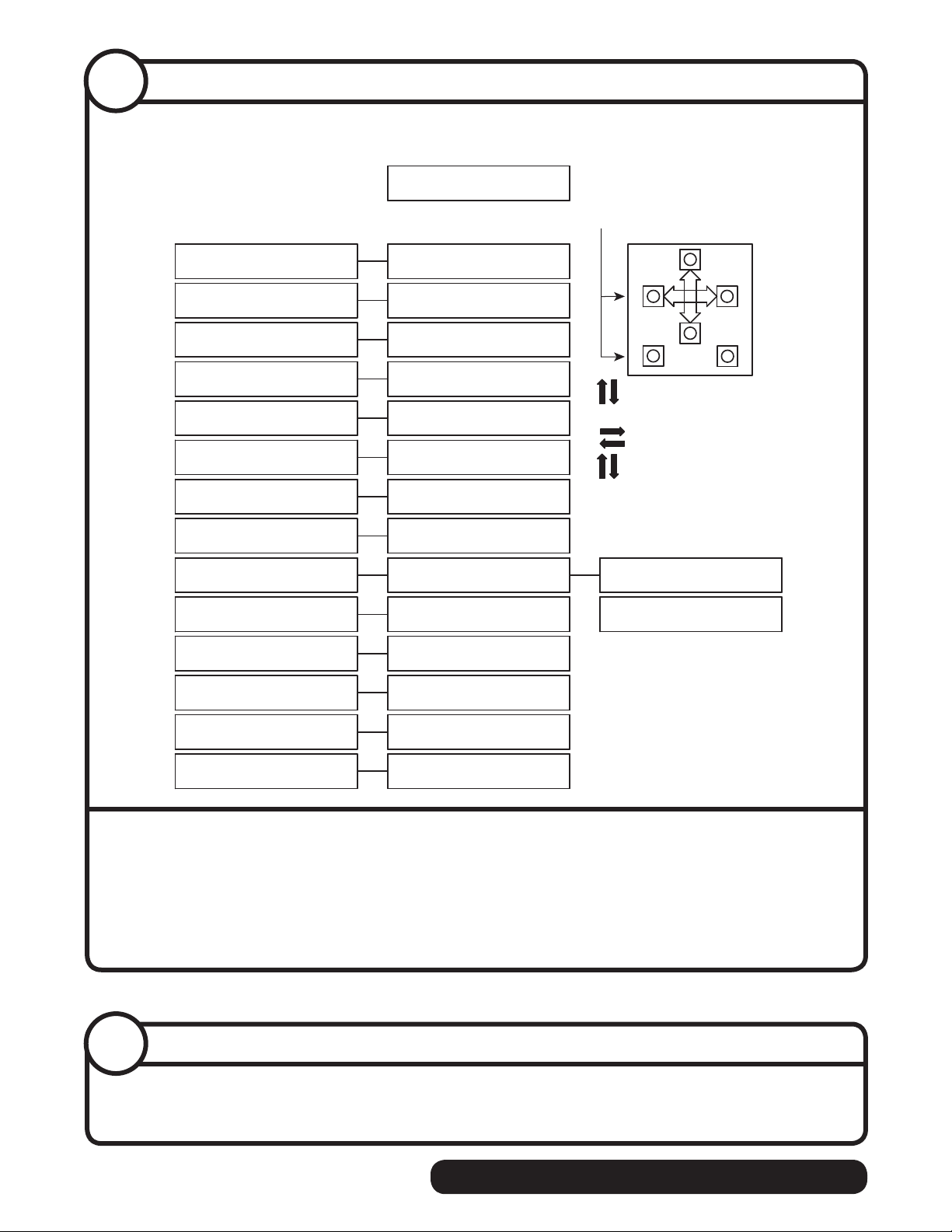
3.7
Agitation adjustments – LANCER FS SERIES
Initialization Screen
(Boot Up Only)
Lancer FS-16
Ver. 0.200
Sub-CatagoryMain Menu
FS-16 Setup
Major/Minor
FS-16 Setup
Config Bonus Key
FS-16 Setup
Soda/Plain Water
FS-16 Setup
Config Dispense Only
FS-16 Setup
PC Mode
FS-16 Setup
PC Time
FS-16 Setup
Ice Stir Off
FS-16 Setup
Ice Stir On
FS-16 Setup
Sold Out
FS-16 Setup
Carb Sensors
FS-16 Setup
Ice Bin Sensors
FS-16 Setup
Valve Code Version
FS-16 Setup
Number Of Valves
FS-16 Setup
Reset Defaults No Yes
Brands Per Side
Bonus Key Setup
V:1 T:F M:S B:W
Soda/Plain Water
V:2 1:S 2:W 3:S 4:W
Dispense Delay
V:1 B1 DLY1
Set PC Mode Menu
Off On
On Time (MSEC)
OFF Time (MIN)
On Time (MSEC)
Selection Sold Out
Upper Lower
1000 500
Ice Bin Optic
12 0.104 0.104
34 0.104 0.104
1 2 3 4
On On On On
Reload Defaults?
V:1 L:2 R:1
05000
00150
01000
Sold Out #1
1000
➊
Cancel
Scrolls through Main Menu
Press "Enter" to enter sub-catagory
Moves curser to right or left
Changes value (number/letter)
Press "Enter" to enter save changes
Press "Cancel" to exit menu
2nd Sub-Catagory
Sold Out #1
Sold Out #1
V:1 B:1
Enter
Off
Lancer FS series only
• Hold down “cancel” and “left button” to get to hidden menu
• Type in code 6655
• Type in 150 minutes “off time” and 1000 milliseconds (1 second of time) as the preferred setting
Note: See Lancer manual for more information
3.8
Agitation adjustments – SERVEND
➊
SerVend models only
No agitation adjustment required
8
self-contained HARMONY • SATELLITE-FILL
Page 9

3.9
Dispenser diverter plate installation – CORNELIUS ED, DF and DB SERIES
ice chute
10-32 nut
➋
ice diverter
(supplied)
gasket
flat washer
gate
mounting
plate
storage bin
apply food-grade
silicone sealant
to this surface
to seal to bin gate
mounting plate
gate
➊
restrictor
plate
flange extends
into storage
bin through
gate opening
Cornelius ED, DF and DB series only
These dispensers require the installation of an ice diverter at the dispenser opening.
• Disassemble chute assembly
• Discard factory restrictor plate
• Replace with alternate diverter plate, ➋ (supplied)
➊
HARMONY • SATELLITE-FILL self-contained
9
Page 10

3.10
Restrictor plate adjustment – CORNELIUS IDC and FLAVOR FUSION
➋
adjust restrictor
plate to fully
open position
➊
Cornelius IDC and Flavor Fusion
These dispensers require the adjustment of the ice restrictor plate.
• Loosen four nuts on ice chute assembly
• Adjust restrictor plate to fully open position
• Replace four nuts and tight to 50 in lbs (max.)
➊
➋
10
self-contained HARMONY • SATELLITE-FILL
Page 11

Louvered docking assembly
Install the louvered docking assembly.
WARNING
• Docking station must be secured in accordance with these instructions to ensure icemaker stability.
• Ventilation openings in the louvered docking station should be clear of obstruction
4
Wall bracket accessory
• Mount louvered docking assembly to wall
bracket accessory
4.1
Undercounter installation requirements Horizon 1000 & 1400 series
Machine stand accessory
• Mount louvered docking assembly to
machine stand accessory
DOCKING STATION: Horizon 1000 & 1400 water- and air-cooled models
(See detail drawing on page 12)
• Position and screw louvered docking assembly to the bottom of counter inside of access panel/
door 1.75" (45mm) from the front edge of the cross brace
• The mounting surface for the louvered docking assembly must be solid.
Do not mount directly onto runners or channels.
• There must be no lip or edge that would hinder the icemaker from sliding in or out of the
louvered docking station
INTAKE AND EXHAUST GRILLE PLACEMENT: Horizon 1000 & 1400 air-cooled models only
(See detail drawing on page 12)
• Position the intake grille cut out in the access panel/door
Note: Icemaker must be aligned with cut out and inside of access panel to provide a tight seal
and prevent recirculation of hot exhaust air.
• Left edge of cutout should be 1.75" (45mm) from the left side of the icemaker
• Bottom edge of cutout should be 1.875" (48mm) from the bottom of the icemaker
• Position supplied exhaust grille at least 18" (458mm) away from intake grille ➎.
Where possible, install exhaust grille to the rear or side of the base cabinet.
• If not using supplied grille, air circulation requirements below must be met:
1000 series: 150 sq. in (967 sq cm) intake air, 150 sq. in. (967 sq. cm) exhaust air
1400 series: 175 sq. in (1129 sq. cm) intake air, 175 sq. in (1129 sq. cm) exhaust air
➋
➊
➌
➍
HARMONY • SATELLITE-FILL self-contained
11
Page 12
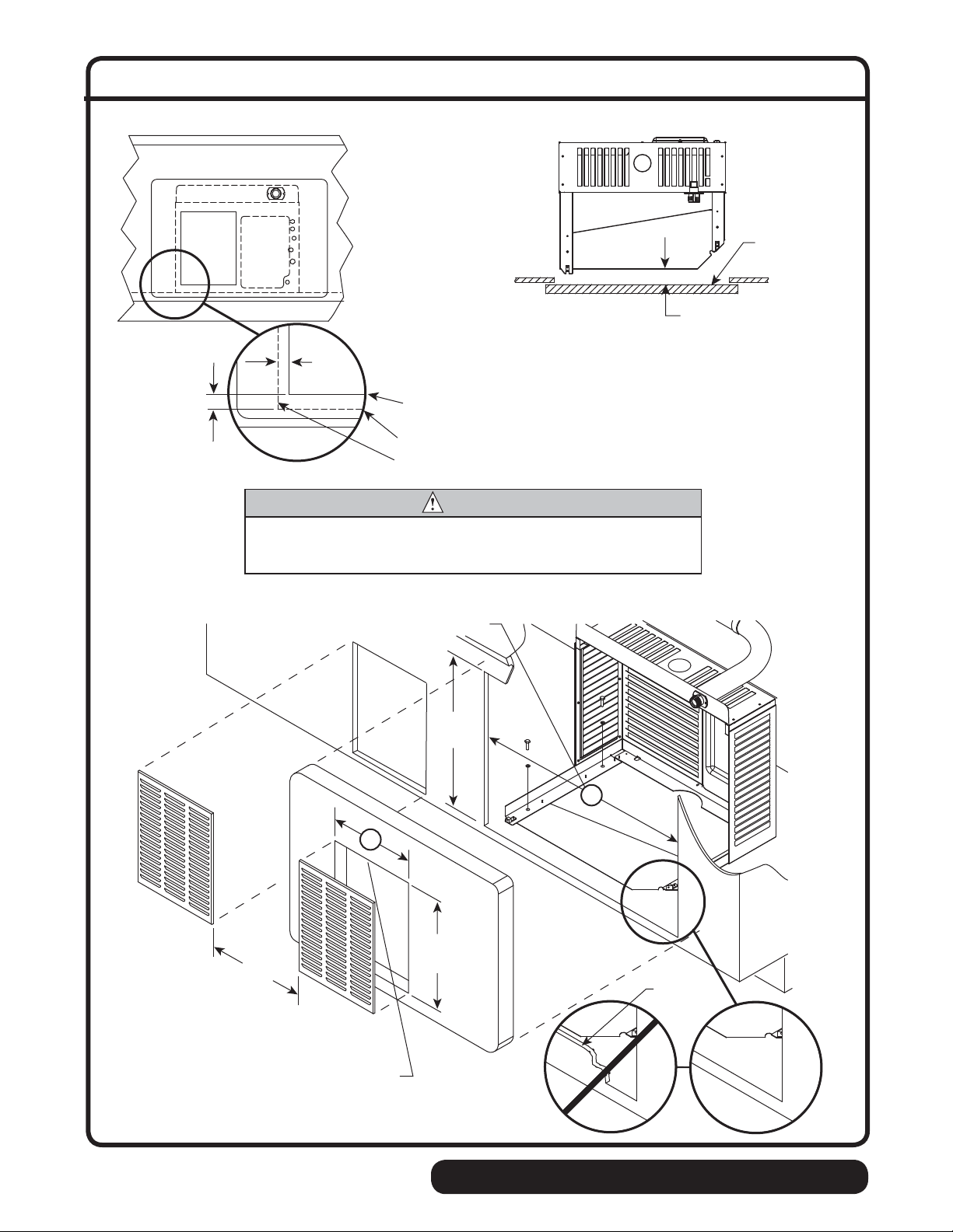
Undercounter installation detail – Horizon 1000 & 1400 series
Front View
1.875"
(48mm)
➍
Top View
CROSSBRACE
➊
➌
1.75"
(45mm)
1000 series - 12"x16" cutout (305x407mm)
1400 series - 16"x16" cutout (407x407mm)
bottom of ice machine
side of ice machine
CAUTION
• Keep ventilation openings in the appliance enclosure clear of obstruction.
• To ensure proper ventilation (if not using supplied grille) carefully review air
circulation speci cations on previous page (4.1)
Access panel/
door on counter
1.75" (45mm)
➎
18" min.
(458mm)
3D Counter View
1000 series - 28.6" min. (727mm)
1400 series - 31.6" min. (303mm)
24.5" min.
(623mm)
CROSSBRACE
16"
(407mm)
No Lip
➋
12
1000 series - 12" (305mm)
1400 series - 16" (407mm)
self-contained HARMONY • SATELLITE-FILL
Page 13

Install the ice transport tube.
Ice transport tube
5
5.1
Ice transport tube installation.
➍
➏
➐
➌
1/4"
➋
Hot Water
160 F (71 C)
➎
➑
➒
➊
1'
➓
Ice transport tube tips
• Insulate entire length of ice transport tube
• Secure ice transport tube ➋ as needed to prevent dips and traps from forming.
For long tube runs see guide on page 19.
• Pitch ice transport tube at least 1/4" per foot (6,4mm/.3m)
• Ice transport tube must drain towards icemaker
Ice transport tube to dispenser
• Be sure tube ends are square
• Heat end of transport tube in cup of 160 F (71 C) hot water to soften and spread with pliers ➎
before making connection to ease assembly
• Push ice transport tube onto icemaker nipple
• Install hose clamp
Ice transport tube to Icemaker
• Be sure tube ends are square
• Heat end of transport tube in cup of 160 F (71 C) hot water to soften and spread with pliers ➎
before making connection to ease assembly
• Push ice transport tube onto icemaker nipple
• Install hose clamp
➐
➓
➍
➑
➊
➌
➏
➒
HARMONY • SATELLITE-FILL self-contained
13
Page 14
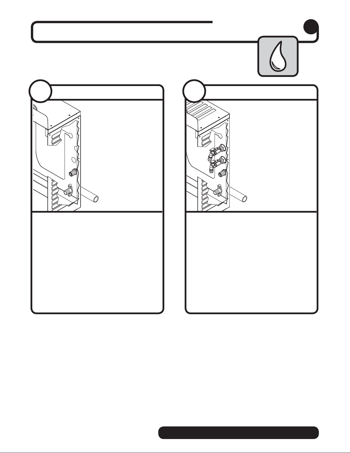
Connect utilities to louvered docking assembly.
External connections
6
6.1
Air-cooled icemakers only
➋
➊
• Remove access panel if necessary
• Install drain line
The rigid drain line from the icemaker
must have at least 1/4" per foot pitch
(6,4mm/0,3m).
• Install icemaker potable water supply
• Replace access panel
➊
.
➋
6.2
Water-cooled icemakers only
➌
➋
➍
➊
• Remove access panel if necessary
• Install drain line
The rigid drain line from the icemaker
must have at least 1/4" per foot pitch.
• Connect cooling water supply
return
• Install ice machine potable water
supply
• Replace access panel
➌
➍
➊.
➋
and
14
self-contained HARMONY • SATELLITE-FILL
Page 15

Connect louvered docking assembly to icemaker.
CAUTION
• Plug must be accessible after nal installation.
• H_E1400A/W 230/50/1) requires a 20 amp circuit (4.00 mm2 wire)
Air-cooled icemakers – follow steps 7.1 through 7.4.
Internal connections
7
7. 1
Ice transport tube
➋
➊
• Slide icemaker into louvered docking
assembly
• Insert ice transport tube all the way into
coupling and tighten nut rmly
➊
➋
7. 2
Potable water and drain lines
➊
• Insert potable water line into valve
• Push drain line over hose barb on
back of evaporator mount
➋
➊
➋
➋
➊
7. 3
• Remove twist tie
• Carefully pass plug thru opening and plug
HARMONY • SATELLITE-FILL self-contained
Power cord
into wall outlet
7. 4
• Position plate into opening and secure
Power cord
with supplied screw
15
Page 16
➋
➊
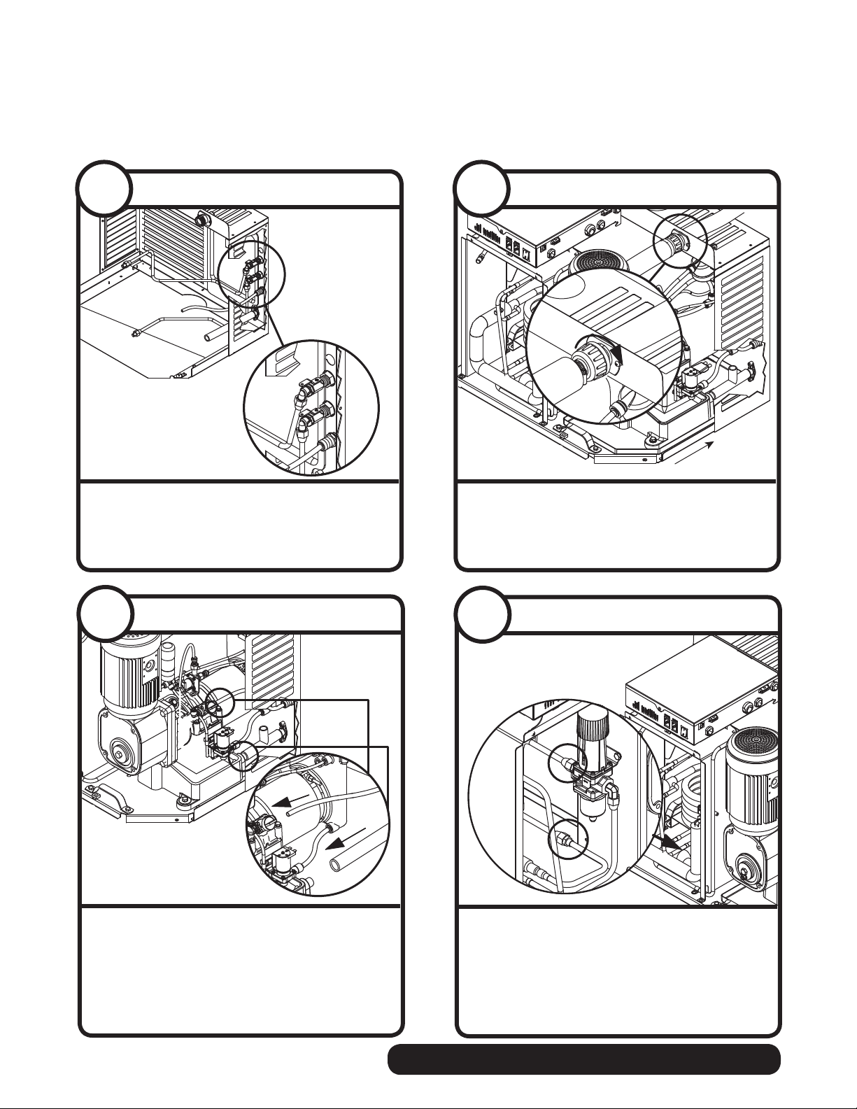
Water-cooled icemakers – follow steps 7.5 through 7.10.
7. 5
• Install icemaker cooling water lines to
Cooling lines
Out
In
louvered docking assembly
7. 6
Ice transport tube
➋
➊
• Slide icemaker into louvered docking
assembly
• Insert ice transport tube into coupling and
tighten nut rmly
➊
➋
7. 7
Potable water and drain lines
➊
• Insert potable water line into valve
• Push drain line over hose barb on
back of evaporator mount
➋
➋
➊
➊
➋
7. 8
• Connect cooling water lines to
• Water valve is set at the factory. DO NOT
Cooling lines and power
Adjustment will void warranty and may damage equipment.
Do not adjust.
ATTENTION INSTALLER
Valve is preset at factory.
icemaker
remove seal or adjust water valve
➊
➋
16
self-contained HARMONY • SATELLITE-FILL
Page 17

7. 9
Power cord
7. 1 0
Power cord
• Remove twist tie
• Carefully pass plug thru opening and plug
into wall outlet
• Position plate into opening and secure
with supplied screw
HARMONY • SATELLITE-FILL self-contained
17
Page 18

Install front cover to icemaker.
Front cover
8
Front cover installation – undercounter
➊
➋
➌
CAUTION
• Keep ventilation openings in the appliance enclosure
clear of obstruction
• To ensure proper ventilation (if not using supplied grille)
carefully review air circulation speci cations in section
4.1
• Remove and discard plastic grille
• Apply supplied gasket material around
entire opening on skin to prevent air
recirculation
• Attach supplied metal grille to opening in
counter door (see section 4.1)
➋
➊
➌
Normal front cover installation
➋
➊
• Slide icemaker cover over machine
ensuring that tabs on back of cover
slip under louvers on back of louvered
docking assembly
• Insert and tighten two screws through
cover and into louvered docking assembly
➊
➋
18
NOTICE
Icemaker MUST be sanitized prior to operation!
Consult Operation and Service Manual provided with icemaker for sanitizing instructions.
self-contained HARMONY • SATELLITE-FILL
Page 19

Long tube run recommendations
max. 2 ft (.6m)
➋
• Pitch ice transport tube to allow melt water to drain towards icemaker
• Secure insulated ice transport tube at least every 2 ft (.6m) to prevent dips or traps
1/4"
➊
➊
1'
➋
HARMONY • SATELLITE-FILL self-contained
19
Page 20

801 Church Lane • Easton, PA 18040, USA
Toll free (877) 612-5086 • +1 (610) 252-7301
www.follettice.com
00159897R05
12/11
 Loading...