

Page 1
208264
Stock Module Identification Plate
Service No.
Module No.
Product
O
M
R
E
S
S
O
R
T
H
E
RM
A
L
L
Y
P
R
O
TE
C
T
E
D
E
a
s
t
o
n
P
e
n
n
s
y
l
v
a
ni
a
U
A
M
P
S
A
M
P
S
VO
L
T
S
N
S
F
P
H
A
S
E
S
I
N
G
L
E
C
H
A
R
G
E
L
O
W
S
I
D
E
P
A
R
T
N
O
P
S
I
G
T
H
E
U
S
A
M
A
D
E
I
N
O
Z
L
L
U
R
C
R
H
Z
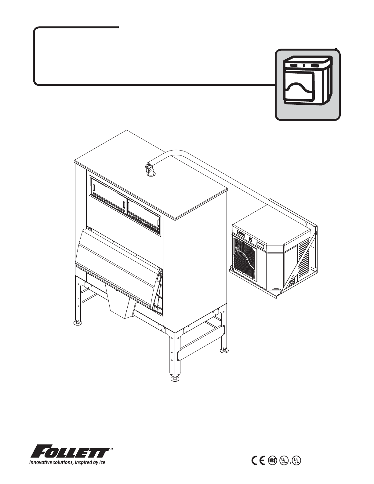
Horizon™ Ice Machine Models with RIDE™ Technology
Installation Instructions for Ice Storage Bins
HCC1000ABS, HMC1000ABS, HCC1400ABS, HMC1400ABS,
HCC1000WBS, HMC1000WBS, HCC1400WBS, HMC1400WBS,
HCE1000ABS, HME1000ABS, HCE1400ABS, HME1400ABS,
HCE1000WBS, HME1000WBS, HCE1400WBS, HME1400WBS
(See model number con gurator on page 2 for details.)
Order parts online
www.follettice.com
self-contained
801 Church Lane • Easton, PA 18040, USA
Toll free (877) 612-5086 • +1 (610) 252-7301
www.follettice.com
a
i
n
a
v
l
y
s
n
n
e
P
O
n
N
o
t
s
E
a
L
ART
E
P
G
N
I
S
E
S
A
H
P
Z
Z
O
H
G
I
S
P
D
E
E
T
G
C
R
S
E
A
T
T
H
C
OL
RO
V
P
N
I
Y
E
E
L
D
D
L
A
I
A
A
M
S
S
U
M
E
W
R
H
O
T
E
L
H
F
S
N
OR T
S
S
E
R
OM
S
P
M
A
S
P
M
A
208264
Stock Module Identification Plate
Module No.
Product
Service No.
00159889R07
Page 2
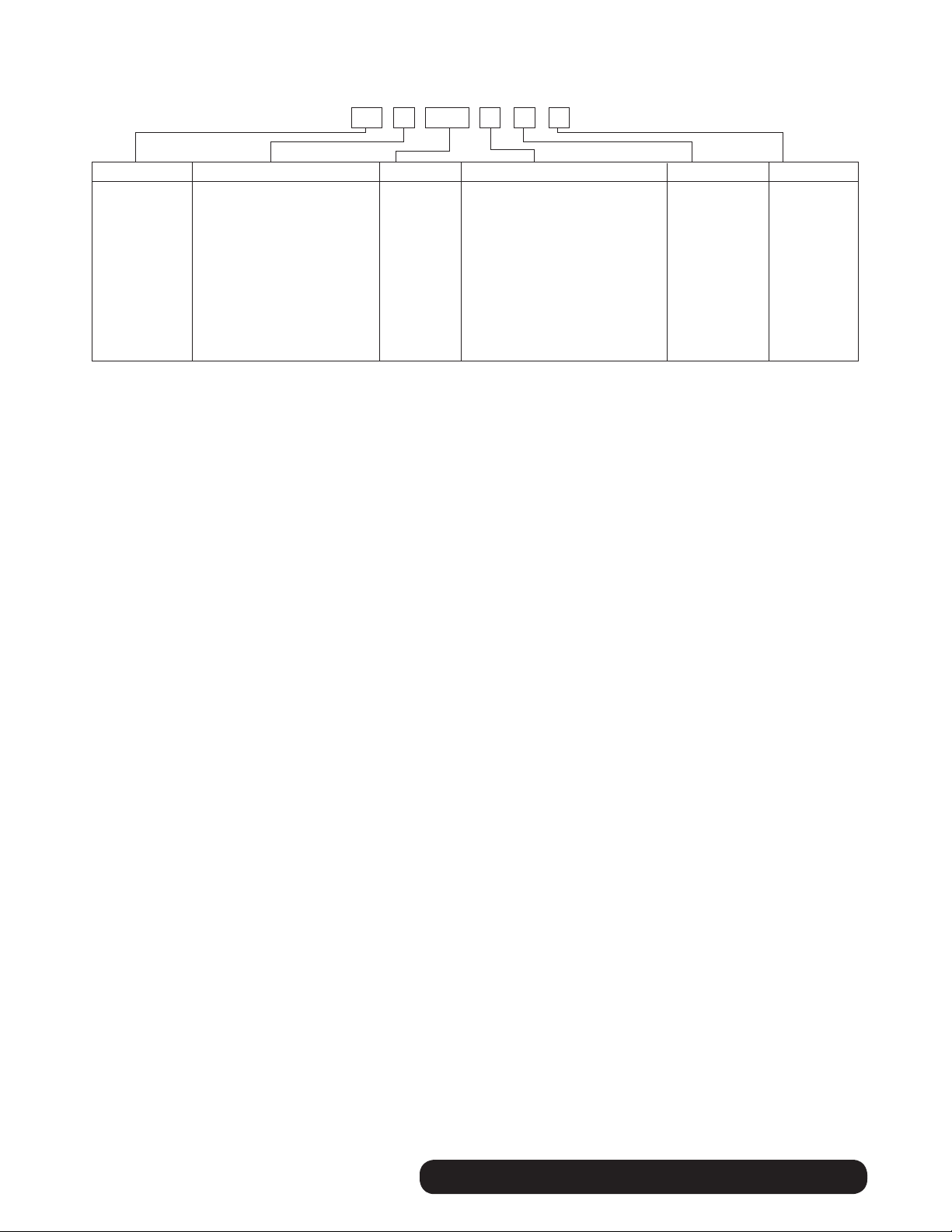
Chewblet® Ice Machine Model Number Configurations
HC 1400CSVA
MC Maestro™
Chewblet
(400 Series)
HC Horizon
Chewblet
(1000, 1400,
1650 Series)
HM Horizon
Micro Chewblet
C 208-230/60/1 (icemaking head)
®
Self-contained only.
D 115/60/1 (icemaking head)
Self-contained and remote. If remote
unit, high side is 208-230/60/1.
E 230/50/1 (icemaking head)
Self-contained only.
F 115/60/1 (icemaking head)
Remote only. High side is
208-230/60/3.
400 up to
454 lbs
(206kg)
1000 up to
1036 lbs
(471kg)
1400 up to
1450 lbs
(658kg)
1650 up to
1580 lbs
(717kg)
CondenserSeriesVoltageIcemaker
A Air-cooled, self-contained
W Water-cooled, self-contained
R Air-cooled, remote condensing unit
N Air-cooled, no condensing unit for
connection to parallel rack system
V Vision™
H Harmony™
B Ice storage bin
J Drop-in
M Ice Manager
diverter valve
system
ConfigurationApplication
S RIDE™
(RIDE remote
ice delivery
equipment)
T Top-mount
2
self-contained BIN • RIDE Technology
Page 3
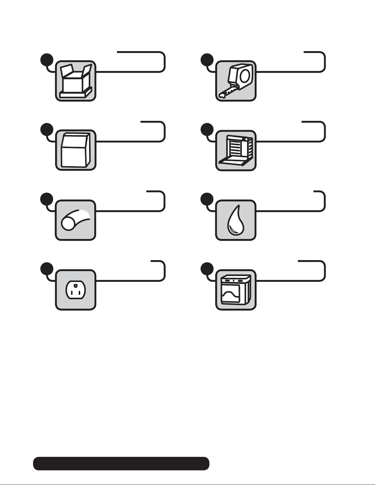
Read and complete the following 8 installation steps
Site preparationUnpack
21
Bin preparation
Ice transport tube
5 6
Louvered docking assembly
43
External connection
Front coverInternal connection
87
BIN • RIDE Technology self-contained
3
Page 4
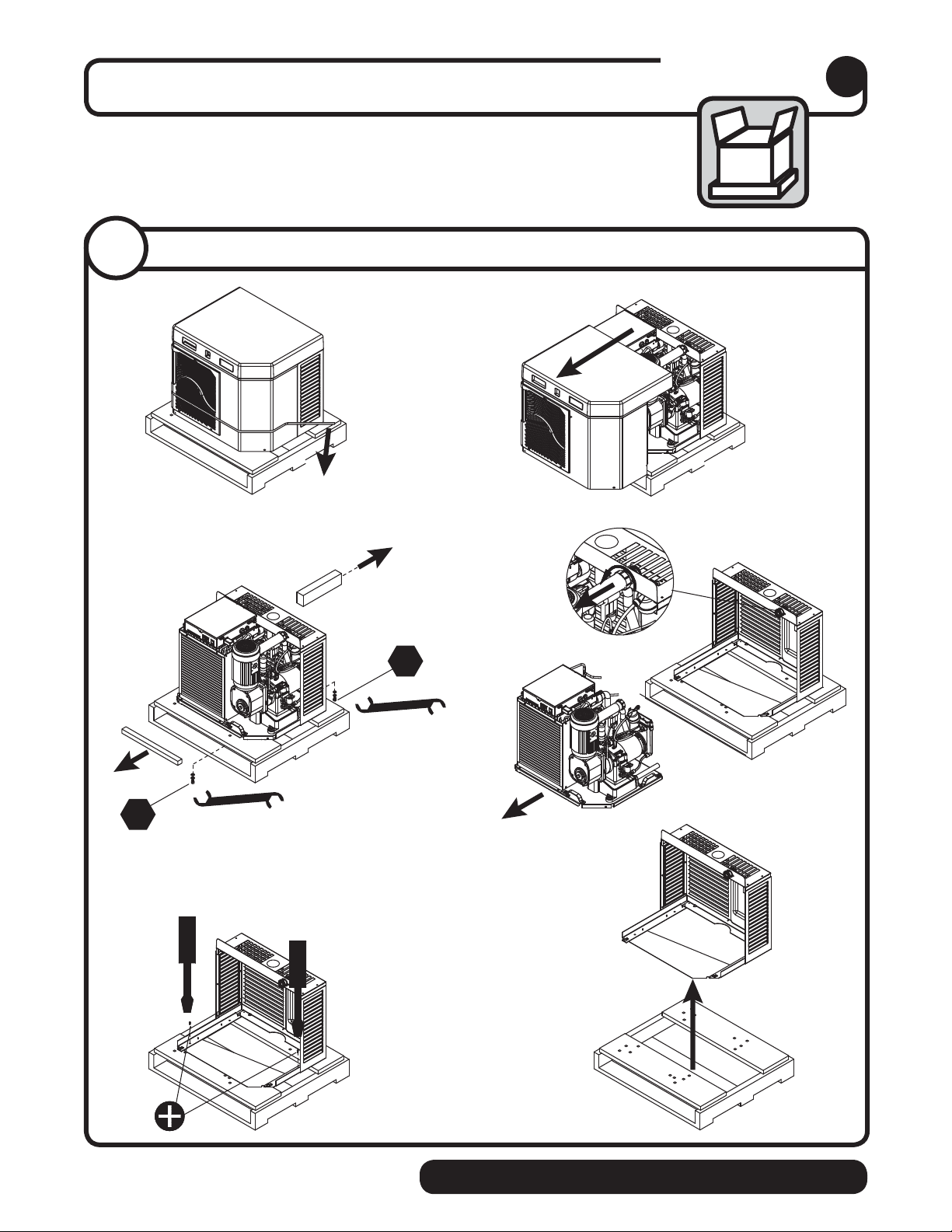
Carefully unpack and inspect the contents of your Follett ice machine.
1/2"
1/2"
➊➋
➌➍
➎➏
Unpack
1
1. 1
Unpack ice machine
4
self-contained BIN • RIDE Technology
Page 5
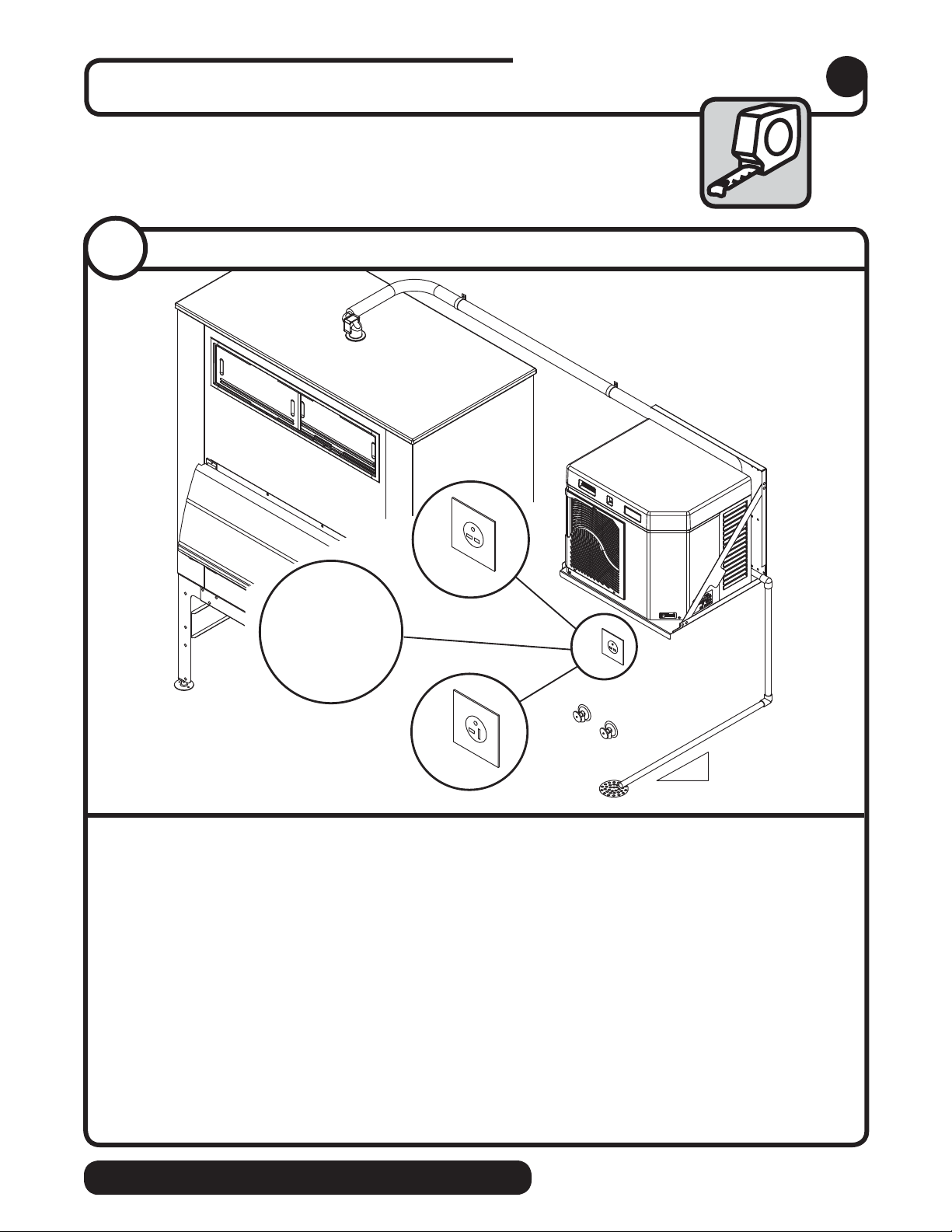
Prepare the installation site.
Provide drainage, water supply and electrical power to within 6 feet (2m)
of ice machine in accordance with local and national codes. Outdoor
installation is not recommended and will void warranty.
Site preparation
2
2.1
2.1
Installation site requirements
2
wire
2
wire
‡
‡
H_E1000A/W
requires 15A circuit,
1.50 mm
H_E1400A/W
requires 20A circuit,
4.00 mm
NEMA
6-15
H_C1000A/W
Electrical
➊
NEMA
6-20
H_C1400A/W
1' (0,3m)
1/4" (6,4mm)
• H_C1000(A/W)BS 208-230/60/1-15 amps • H_C1400(A/W)BS 208-230/60/1-20 amps
• H_E1000(A/W)BS 230/50/1-15 amps‡ • H_E1400(A/W)BS 230/50/1-20 amps
(H_E1000A/W requires 15A circuit, 1.50 mm2 wire) (H_E1400A/W requires 20A circuit, 4.00 mm2 wire)
‡ Plug must be provided by end user & must conform to standard EN 60 335-2-24 of the end destination.
Potable water supply
➋
‡
• 10-70 psi (69-483kpa)
• 45 to 90 F (7 to 32 C)
• Follett recommends the use of an in-line water ltration system (#00130286)
Condenser water supply for water-cooled systems
➌
• 10 psi min.; 150 psi max. (69kpa min.; 1034kpa max.)
• 45 to 90 F (7 to 32 C)
• 1.5 gallons per minute (5.68 liters per minute)
Drain
➍
• The drain line from the ice machine must have at least 1/4" per foot pitch (6,4mm/0,3m)
BIN • RIDE Technology self-contained
5
Page 6
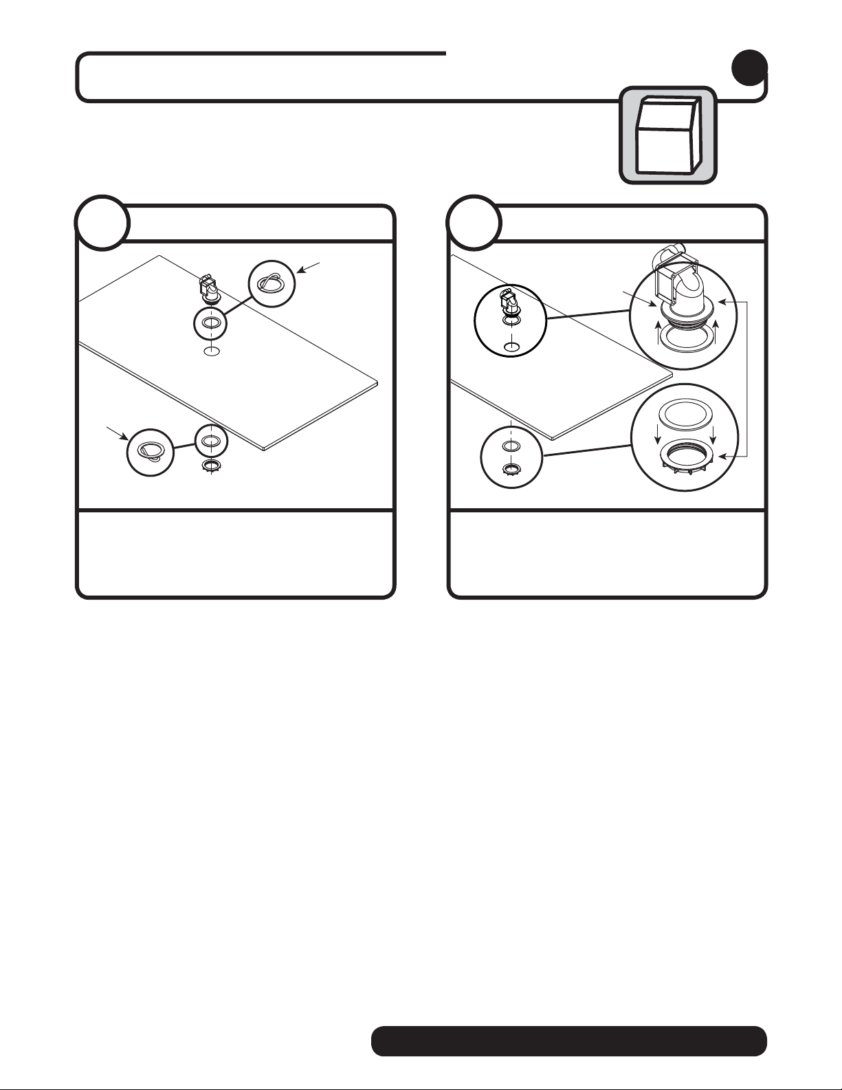
Prepare the bin
Bin preparation
3
3.1
• Remove protective tape from gaskets
Bin top preparation
3.2
Bin top preparation
➋
➊
➊
• Apply gaskets
• Install shuttle actuator
dispenser top and secure with locking nut
➊
through
➋
➌
➌
6
self-contained BIN • RIDE Technology
Page 7
Louvered docking assembly
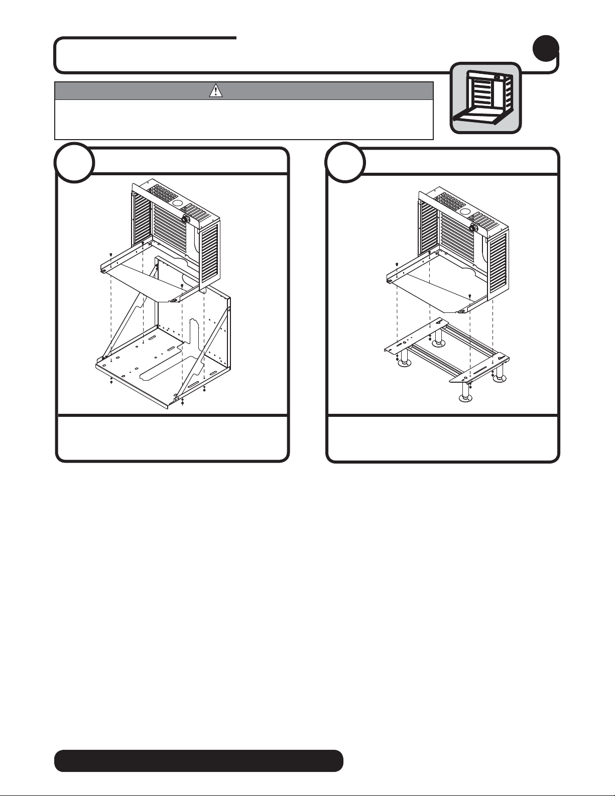
Install the louvered docking assembly.
WARNING
• Docking station must be secured in accordance with these instructions to ensure ice machine
stability.
• Ventilation openings in the louvered docking station should be clear of obstruction
4
4.1
• Mount louvered docking assembly to wall
Wall bracket accessory
bracket accessory
4.2
• Mount louvered docking assembly to
Machine stand accessory
machine stand accessory
BIN • RIDE Technology self-contained
7
Page 8
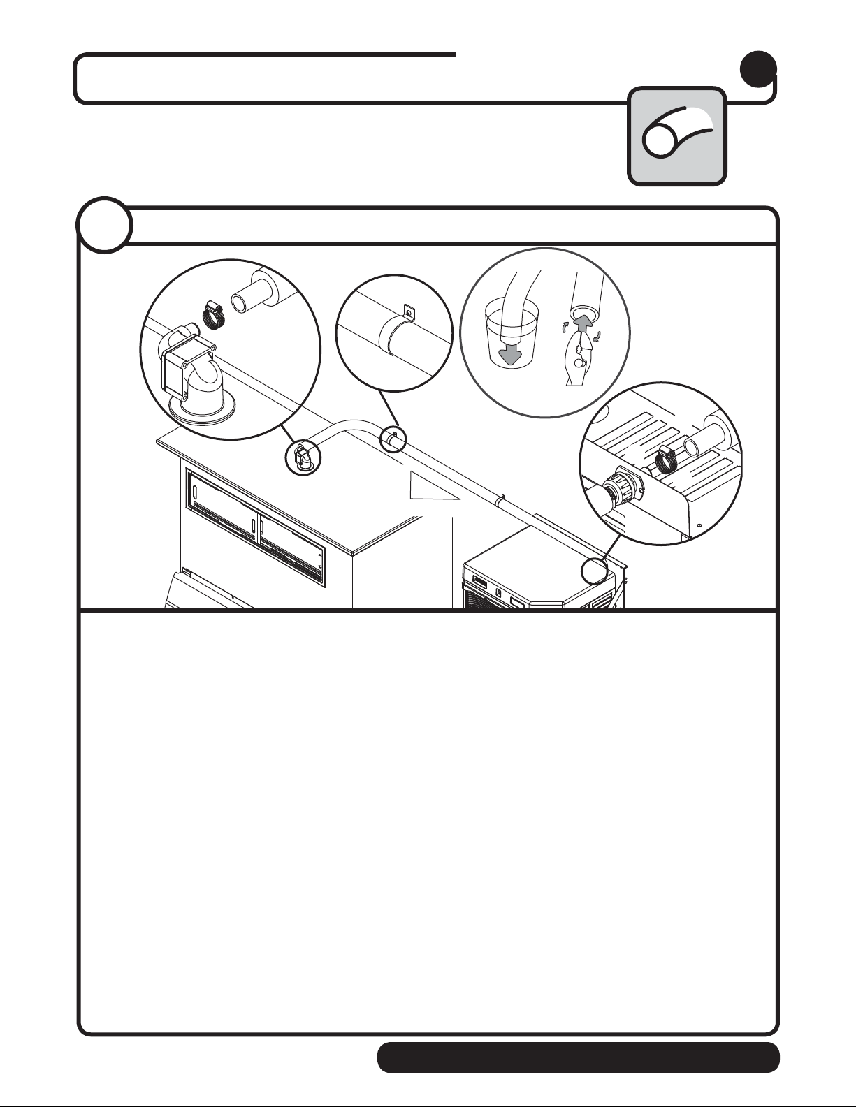
Install the ice transport tube.
Ice transport tube
5
5.1
Ice transport tube installation
Hot Water
160 F (71 C)
¡
1/4˝ (6,4mm)
1' (0,3m)
Ice transport tube tips
• Insulate entire length of ice transport tube
• Secure ice transport tube ➋ as needed to prevent dips and traps from forming. For long tube
runs see guide on page 14.
• Pitch ice transport tube at least 1/4" per foot (6,4mm/.3m)
• Ice transport tube must drain towards ice machine
➊
➌
¢
Ice transport tube to bin
• Be sure tube ends are square
• Heat end of transport tube in cup of 160 F (71 C) hot water to soften and spread with pliers ➎
before making connection to ease assembly
• Push ice transport tube onto ice machine nipple
• Install hose clamp
Ice transport tube to Ice machine
• Be sure tube ends are square
• Heat end of transport tube in cup of 160 F (71 C) hot water to soften and spread with pliers ➎
before making connection to ease assembly
• Push ice transport tube onto ice machine nipple
• Install hose clamp
8
➐
➓
➍
➏
➑
➒
self-contained BIN • RIDE Technology
Page 9
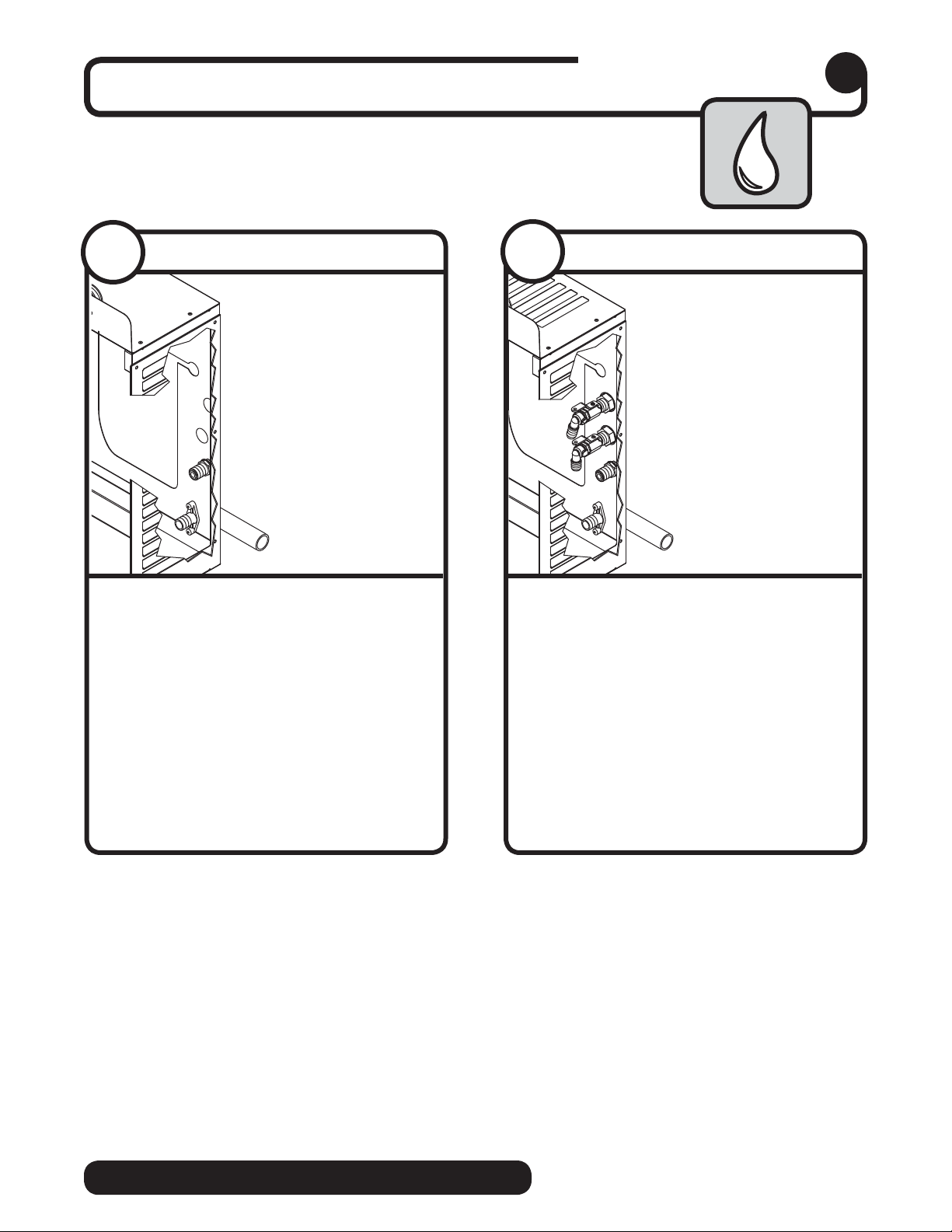
Connect utilities to louvered docking assembly.
External connections
6
6.1
Air-cooled ice machines only
➋
➊
• Remove access panel if necessary
• Install drain line
The rigid drain line from the ice machine
must have at least 1/4" per foot pitch
(6,4mm/0,3m).
• Install ice machine potable water
supply
• Replace access panel
➋
➊
.
6.2
Water-cooled ice machines only
➌
➋
➍
➊
• Remove access panel if necessary
• Install drain line
The rigid drain line from the ice machine
must have at least 1/4" per foot pitch.
• Connect cooling water supply
return
• Install ice machine potable water
supply
• Replace access panel
➌
➍
➊.
➋
and
BIN • RIDE Technology self-contained
9
Page 10
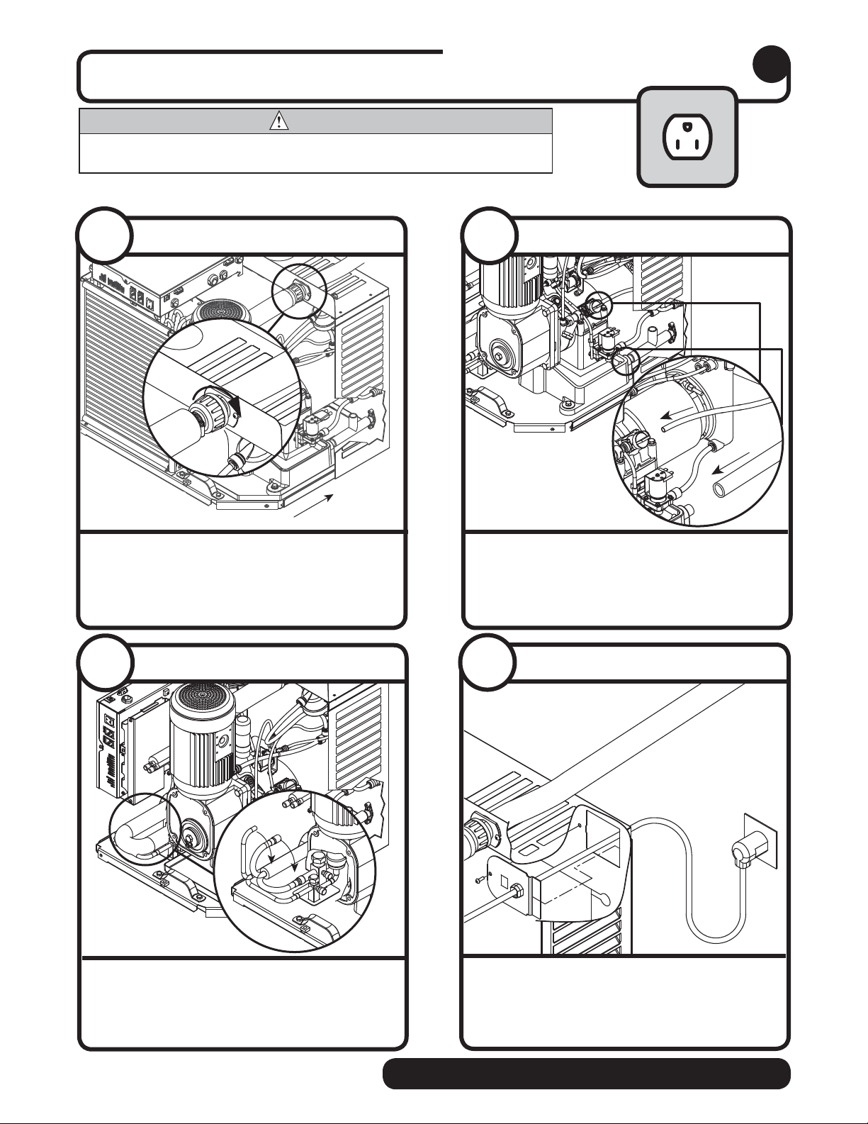
Connect louvered docking assembly to ice
machine.
CAUTION
• Plug must be accessible after nal installation.
• H_E1400A/W 230/50/1 requires a 20A circuit (4.00 mm2 wire)
Air-cooled ice machines – follow steps 7.1 through 7.4.
Internal connections
7
7. 1
Ice transport tube
➋
➊
• Slide ice machine into louvered docking
assembly
• Insert ice transport tube all the way into
coupling and tighten nut rmly
➊
➋
7. 2
Potable water line
➊
• Insert potable water line into valve
• Push drain line over hose barb on
back of evaporator mount
➋
➊
➋
➋
➊
7. 3
Power cord
➊
• Remove twist tie
• Carefully pass plug thru opening and plug
into wall outlet
10
7. 4
• Position plate into opening and secure
self-contained BIN • RIDE Technology
Power cord
with supplied screw
Page 11
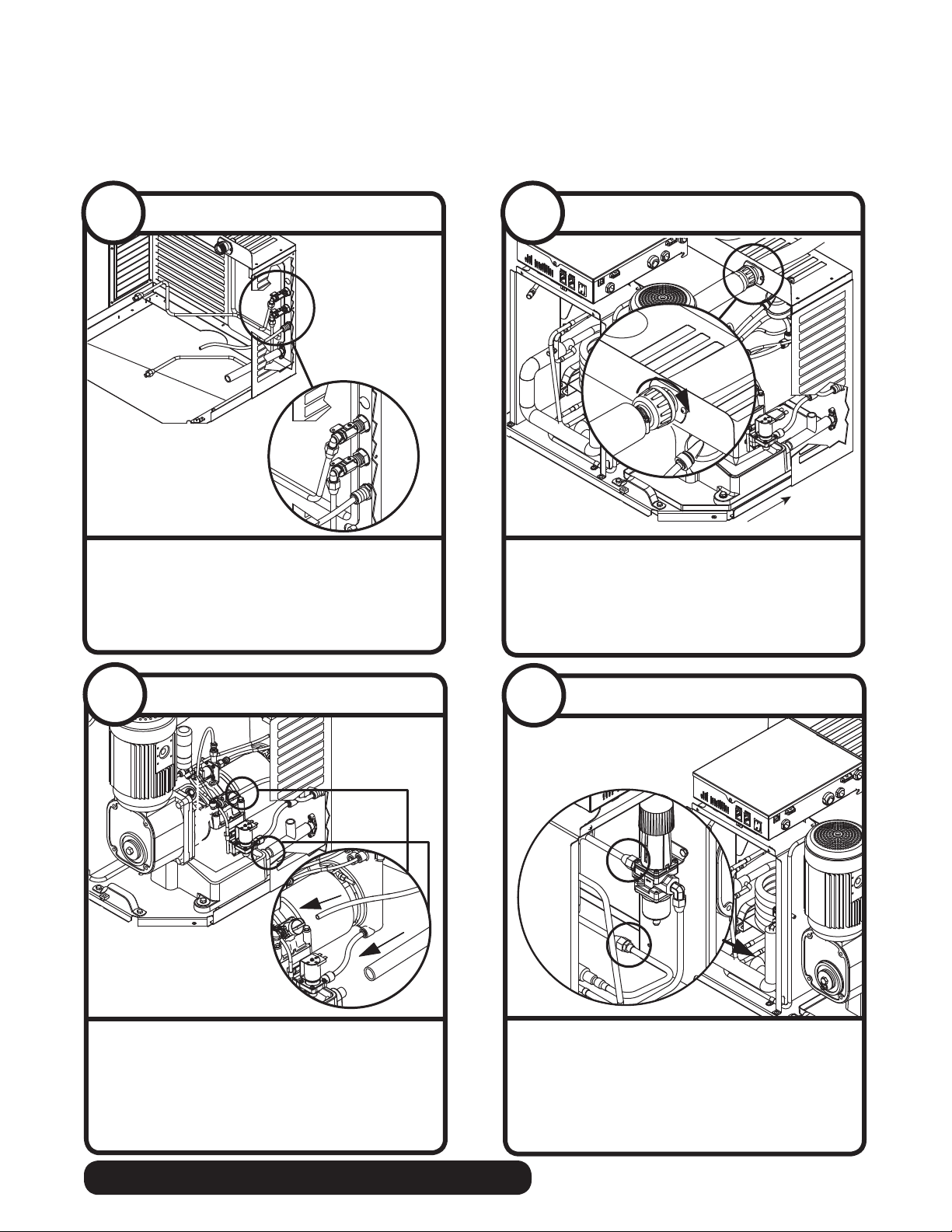
➋
➊
Water-cooled ice machines – follow steps 7.5 through 7.10.
7. 5
• Install ice machine cooling water lines to
Cooling lines
Out
In
louvered docking assembly
7. 6
Ice transport tube
➋
➊
• Slide ice machine into louvered docking
assembly
• Insert ice transport tube into coupling and
tighten nut rmly
➊
➋
7. 7
Potable water and drain lines
➊
➋
➊
➋
• Insert potable water line into valve
• Push drain line over hose barb on back of
evaporator mount
➊
➋
Cooling lines and power
7. 8
Adjustment will void warranty and may damage equipment.
Do not adjust.
ATTENTION INSTALLER
Valve is preset at factory.
• Connect cooling water lines to ice
machine
• Water valve is set at the factory. DO NOT
remove seal or adjust water valve
➊
➋
BIN • RIDE Technology self-contained
11
Page 12
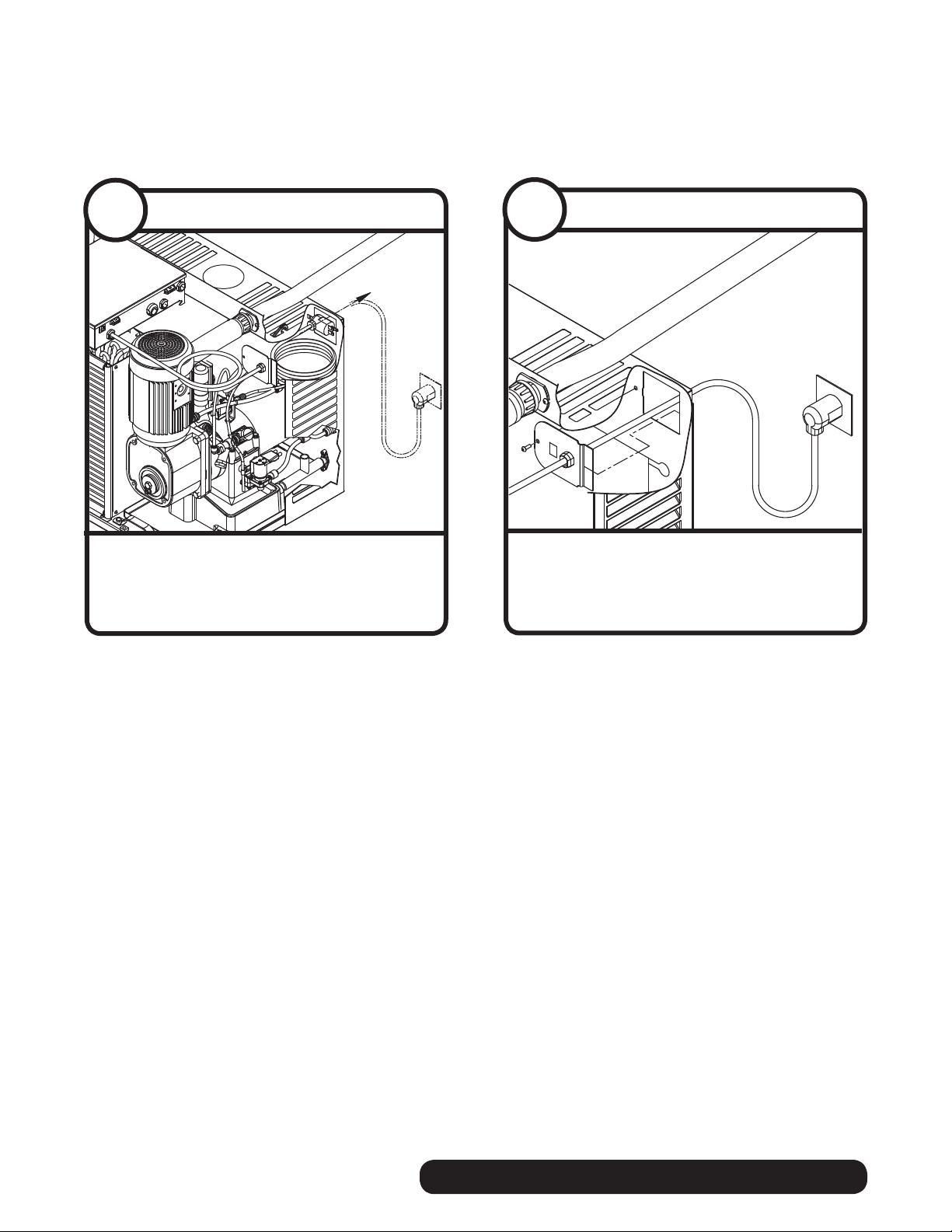
7. 9
Power cord
7. 1 0
Power cord
• Remove twist tie
• Carefully pass plug thru opening and plug
into wall outlet
• Position plate into opening and secure
with supplied screw
12
self-contained BIN • RIDE Technology
Page 13
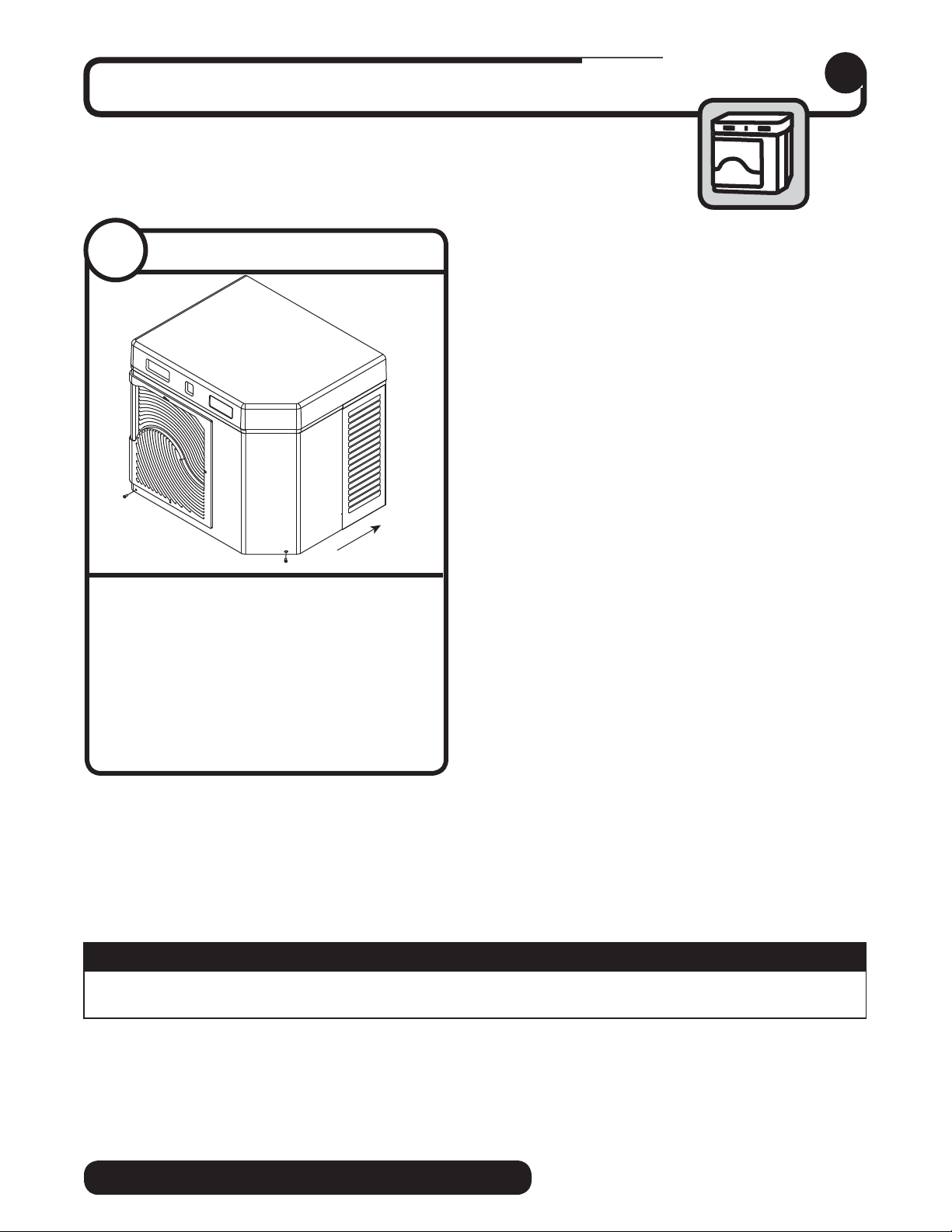
Install front cover to ice machine.
Front cover
8
8.1
Water-cooled ice machines only
➋
➊
• Slide ice machine cover over machine
ensuring that tabs on back of cover
slip under louvers on back of louvered
docking assembly
• Insert and tighten two screws through
cover and into louvered docking assembly
➊
➋
NOTICE
Ice machine MUST be sanitized prior to operation!
Consult Operation and Service Manual provided with ice machine for sanitizing instructions.
BIN • RIDE Technology self-contained
13
Page 14
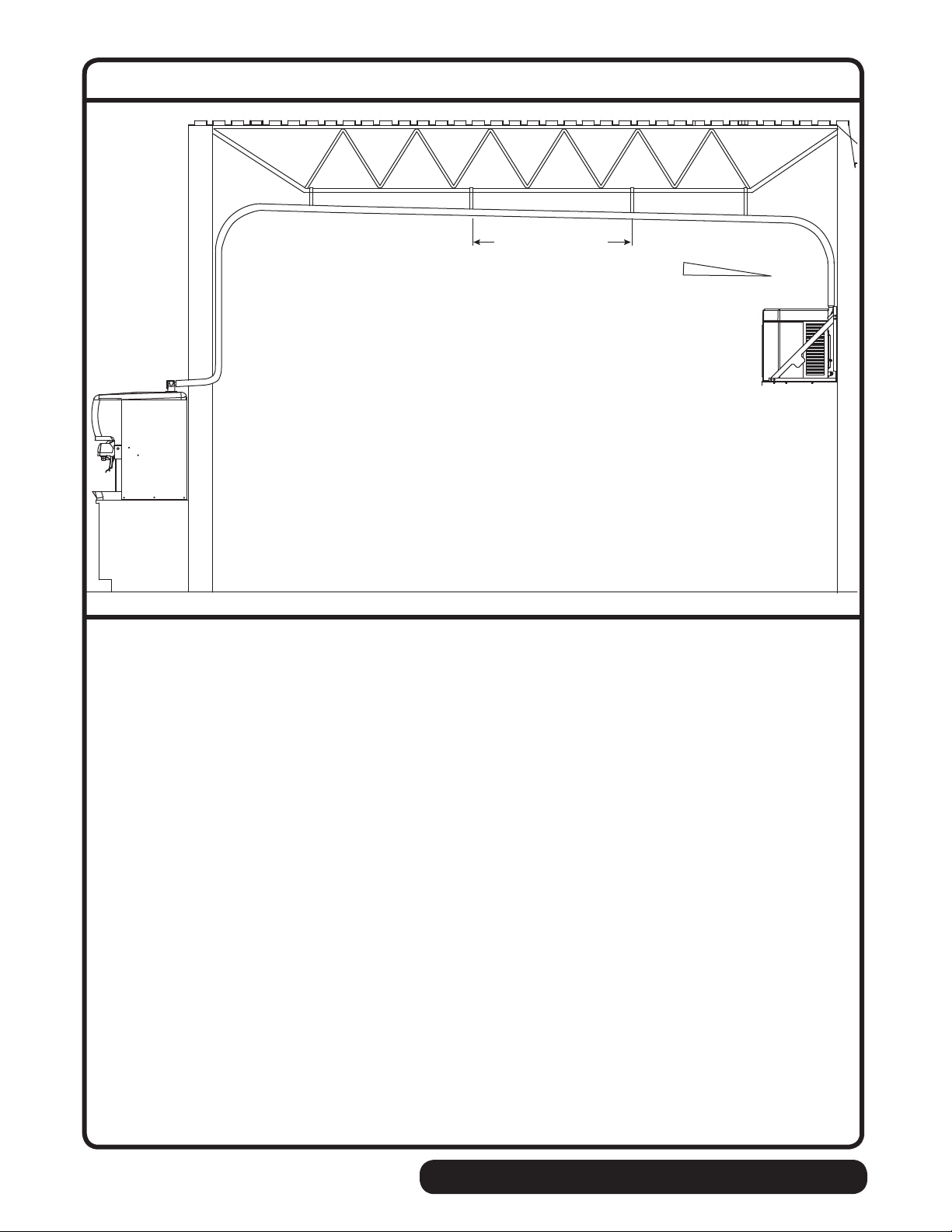
Long tube run recommendations
max. 2 ft (0,6m)
1/4" (6,4mm)
1' (0,3m)
• Pitch ice transport tube to allow melt water to drain towards ice machine
• Secure insulated ice transport tube at least every 2 ft (0,6m) to prevent dips or traps
➊
➋
14
self-contained BIN • RIDE Technology
Page 15

BIN • RIDE Technology self-contained
15
Page 16
Horizon, Maestro, Harmony, Ice Manager, SafeCLEAN, Sani-Sponge, RIDE and Vision are trademarks of Follett Corporation.
Chewblet is a registered trademark of Follett Corporation, registered in the US.
801 Church Lane • Easton, PA 18040, USA
Toll free (877) 612-5086 • +1 (610) 252-7301
www.follettice.com
00159889R07
3/12
 Loading...