

Page 1

E
N
G
L
I
S
H
E
S
P
A
Ñ
O
L
I
T
A
L
I
A
N
O
F
R
A
N
Ç
A
I
S
D
E
U
T
S
C
H
1
Contents
Important Safety Instructions . . . . .2
Connecting Up . . . . . . . . . . . . . . .4
Distributor List . . . . . . . . . . . . . .57
Introduction . . . . . . . . . . . . . . . . .5
Rear Panel Connections and
switches . . . . . . . . . . . . . . . . . . . .5
Getting Started . . . . . . . . . . . . . . .5
Facilities and Controls . . . . . . . . .6
Obtaining a good quality vocal
sound . . . . . . . . . . . . . . . . . . . . . .9
Obtaining a good quality electric
guitar sound . . . . . . . . . . . . . . . . .9
Impoving sound quality using the 3-
band Equaliser . . . . . . . . . . . . . . .10
Mixing Down . . . . . . . . . . . . . . .10
A Beginner’s Guide to
Compression . . . . . . . . . . . . . . . .11
A Beginner’s Guide to
Equalisation . . . . . . . . . . . . . . . .13
Frequently Asked Questions . . . .13
Troubleshooting . . . . . . . . . . . . .14
Contacting Us . . . . . . . . . . . . . . .14
English
Inhalt
Wichtige Sicherheitsvorkehrungen .2
Anschlüsse herstellen . . . . . . . . . . .4
Vertriebsliste . . . . . . . . . . . . . . . .57
Einfürung in den TrakMaster . . . .15
Rückseitige Anschlüsse und
Schalter . . . . . . . . . . . . . . . . . . . .15
Erste Schritte . . . . . . . . . . . . . . . .15
Komponenten unde Regler . . . . .16
Hochwertigen Gegangssound
Erzeugen . . . . . . . . . . . . . . . . . .19
Hochwertigen E-gitarrensound
Erzeugen . . . . . . . . . . . . . . . . . .20
Klangqualität mit dem 3-Band-EQ
Verbessern . . . . . . . . . . . . . . . . .20
Abmischen . . . . . . . . . . . . . . . . .21
Kompressions-anleitung für
Einsteiger . . . . . . . . . . . . . . . . . .21
EQ-anleitung für Einsteiger . . . . .23
FAQs . . . . . . . . . . . . . . . . . . . . .24
Fehlersuche . . . . . . . . . . . . . . . . .24
Kontaktaufnahme . . . . . . . . . . . .24
Deutsch
Table des matières
Consignes de sécurité . . . . . . . . . .3
Connexions . . . . . . . . . . . . . . . . .4
Distributeurs . . . . . . . . . . . . . . . .57
Introduction . . . . . . . . . . . . . . .25
Commandes et Connecteurs en Face
Arriere . . . . . . . . . . . . . . . . . . . .25
Prise en Main . . . . . . . . . . . . . . .25
Commande et Réglages . . . . . . . .26
Obtention d’une Bonne Prise de
Voix . . . . . . . . . . . . . . . . . . . . . .29
Obtention d’un Son de Guitare
Électrique de Bonne Qualité . . . .30
Amélioration de la Qualité Sonore
par Correction . . . . . . . . . . . . . .30
Mixage Final . . . . . . . . . . . . . . . .31
Compression, mode d'emploi . . . .31
Correction, mode d’emploi . . . . .33
Questions-Réponses . . . . . . . . . .34
Assistance . . . . . . . . . . . . . . . . . .34
Contacts . . . . . . . . . . . . . . . . . . .34
Français
Indice
Importtanti Istruzioni per la
Sicurezza . . . . . . . . . . . . . . . . . . .3
Connessioni . . . . . . . . . . . . . . . . .4
Lista dei Distributori . . . . . . . . . .57
Introduzione . . . . . . . . . . . . . . . .35
Connessioni e Pulsanti del Pannello
Posteriore . . . . . . . . . . . . . . . . . .35
Primo Approccio . . . . . . . . . . . . .35
Funzioni e controlli . . . . . . . . . . .36
Ottenere un Suono Vocale di Buona
Qualita . . . . . . . . . . . . . . . . . . . .39
Ottenere un Suono di Chitarra
Elettrica di Buona Qualita . . . . . .40
Migliorare la Qualita del Suono
Utilizzando L’equalizzatore . . . . .40
Missaggio . . . . . . . . . . . . . . . . . .41
Guida alla Compressione . . . . . . .41
Guida all’equallizzazione . . . . . . .43
Domande e Risposte . . . . . . . . . .44
Risoluzione dei Problemi . . . . . .44
Come Contattarci . . . . . . . . . . . .44
Italiano
Contenido
Instrucciones Importantes de
Seguridad . . . . . . . . . . . . . . . . . . .3
Conexionado . . . . . . . . . . . . . . . .4
Lista de Distribuidores . . . . . . . . .57
Introduccion . . . . . . . . . . . . . . . .45
Conexiones y Controles del Panel
Trasero . . . . . . . . . . . . . . . . . . . .45
Inicio . . . . . . . . . . . . . . . . . . . . .45
Prestaciones y Controles . . . . . . .46
Como Obtener una Gran Calidad de
un Sonido Vocal . . . . . . . . . . . . .49
Obtener una Guitarra Electrica de
Gran Calidad . . . . . . . . . . . . . . . .50
Mejorar la Calidad Mediante el
Ecualizador . . . . . . . . . . . . . . . . .50
Mezclando . . . . . . . . . . . . . . . . .51
Guia de Compresion . . . . . . . . . .51
Guia de Ecualizacion . . . . . . . . . .53
Preguntas Mas Comunes . . . . . . .54
Problemas . . . . . . . . . . . . . . . . . .54
Español
Page 2

2
Important Safety Instructions / Wichtige Sicherheitshinweise
IMPORTANT SAFETY INSTRUCTIONS
Read all of these instructions and save them for future reference. Follow all warnings and
instructions marked on the unit.
● Do not obstruct air vents in the rear panel. Do not insert objects through any
apertures.
● Do not use a damaged or frayed power cord.
● Unplug the unit before cleaning. Clean with a damp cloth only. Do not spill liquid
on the unit.
● Ensure adequate airflow around the unit to prevent overheating. We recommend
leaving a blank 1U panel above the unit to aid ventilation.
● Unplug the unit and refer servicing to qualified service personnel under the following
conditions:
If the power cord or plug is damaged; if liquid has entered the unit; if the unit has
been dropped or the case damaged; if the unit does not operate normally or exhibits a
distinct change in performance. Adjust only those controls that are covered by the
operating instructions.
● Do not defeat the safety purpose of the polarised or grounding-type plug. A polarised
plug has two blades with one wider than the other. A grounding type plug has two
blades and a third grounding prong. The wider blade or the third prong are provided
for your safety. When the plug provided does not fit into your outlet, consult an
electrician for replacement of the obsolete outlet.
WARNING: THIS UNIT MUST BE EARTHED BY THE POWER CORD
UNDER NO CIRCUMSTANCES SHOULD THE MAINS EARTH BE
DISCONNECTED
FROM THE MAINS LEAD.
This unit is capable of operating over a range of mains voltages as marked on the rear
panel. Ensure correct mains voltage setting and correct fuse before connecting mains
supply. Do not change mains voltage settings while mains supply is connected.
To avoid the risk of fire, replace the mains fuse only with the correct value fuse, as
marked on the rear panel.
The internal power supply unit contains no user serviceable parts. Refer all servicing to a
qualified service engineer, through the appropriate Focusrite dealer.
WICHTIGE SICHERHEITSVORKEHRUNGEN
Lesen Sie alle Anleitungen und bewahren Sie sie gut auf. Beachten Sie alle Warnungen und
Anweisungen auf dem Gerät.
● Blockieren Sie nicht die rückseitigen Belüftungsöffnungen. Stecken Sie keine Objekte durch
Geräteöffnungen.
● Benutzen Sie kein beschädigtes oder brüchiges Netzkabel.
● Ziehen Sie vor der Reinigung des Geräts den Netzstecker. Benutzen Sie zur Reinigung nur ein
feuchtes Tuch. Verschütten Sie keine Flüssigkeit auf dem Gerät.
● Sorgen Sie für eine ausreichende Luftzufuhr in der Umgebung des Geräts, um eine Überhitzung
zu vermeiden. Lassen Sie am besten 1 HE über dem Gerät frei, um die Belüftung zu fördern.
● In folgenden Fällen sollten Sie das Gerät vom Stromnetz trennen und zur Wartung qualifiziertem
Fachpersonal übergeben:
Wenn Netzkabel oder Netzstecker beschädigt sind. Wenn Flüssigkeit ins Gerät gelangt ist. Wenn
das Gerät fallen gelassen oder das Gehäuse beschädigt wurde. Wenn das Gerät nicht normal
funktioniert oder die Betriebsweise sich stark verändert hat. Stellen Sie nur die Regler ein, die in
der Bedienungsanleitung besprochen werden.
● Setzen Sie die Sicherheitsfunktion des polarisierten oder geerdeten Steckers nicht außer Kraft.
Ein polarisierter Stecker hat zwei flache, unterschiedlich breite Pole. Ein geerdeter Stecker hat
zwei flache Pole und einen dritten Erdungsstift. Der breitere Pol oder der dritte Stift dient Ihrer
Sicherheit. Wenn der vorhandene Stecker nicht in Ihre Steckdose passt, lassen Sie die veraltete
Steckdose von einem Elektriker ersetzen.
ACHTUNG: DIESES GERÄT MUSS ÜBER DAS NETZKABEL GEERDET
WERDEN
UNTER KEINEN UMSTÄNDEN DARF DIE ERDUNG DES
NETZKABELS UNTERBROCHEN WERDEN.
Der Netzspannungsbereich, in dem das Gerät betrieben werden kann, ist auf der Rückseite vermerkt.
Achten Sie auf die korrekte Netzspannungs-Einstellung und die korrekte Sicherung, bevor Sie einen
Netzanschluss herstellen. Ändern Sie die Netzspannungs-Einstellungen nicht, solange der
Netzanschluss besteht.
Um das Risiko eines Brandes auszuschließen, ersetzen Sie die Netzsicherung nur durch eine
Sicherung mit korrektem Nennwert. Dieser ist auf der Geräte-Rückseite vermerkt.
Das interne Netzteil enthält keine Bauteile, die vom Anwender gewartet werden können. Überlassen
Sie die Wartung einem qualifizierten Wartungstechniker, den Ihr Focusrite Fachhändler gern
vermittelt.
E
N
G
L
I
S
H
D
E
U
T
S
C
H
Page 3
3
Consignes de sécurité/Importanti Istruzioni per la Sicurezza/Instrucciones Importantes de Seguridad
E
S
P
A
Ñ
O
L
I
T
A
L
I
A
N
O
F
R
A
N
Ç
A
I
S
CONSIGNES DE SÉCURITÉ
Lisez toutes ces instructions avec attention et conservez-les pour
pouvoir vous y reporter ultérieurement. Tenez compte de tous
les avertissements et de toutes les instructions indiquées sur
l’appareil.
● Veillez à ne pas obstruer les ouïes de ventilation de la face
arrière. N’insérez aucun objet dans l’appareil.
● N’utilisez en aucun cas un cordon d’alimentation endommagé
ou dénudé.
● Débranchez l’appareil avant de le nettoyer. Nettoyez l’appareil
avec un chiffon humide. Ne versez pas de liquide sur
l’appareil.
● Débranchez l’appareil et demandez conseil auprès d’un
personnel qualifié dans chacun des cas suivants :
Si le cordon d’alimentation ou la prise secteur sont
endommagés ; si un liquide pénètre dans l’appareil ; si
l’appareil tombe ou si le châssis a été endommagé ; si
l’appareil ne fonctionne pas correctement ou si ses
performances semblent altérées ; n’utilisez que les commandes
dont les fonctions vous sont présentées dans ce manuel.
● Respectez les polarités ou la mise à la terre de la prise secteur.
Une prise secteur avec mise à la terre est équipée de deux
plots et d’une borne de masse. Cette borne assure votre
sécurité. Si la fiche du cordon secteur de l’appareil n’est pas
compatible avec votre prise secteur, consultez un électricien
pour le remplacement de la prise murale obsolète.
AVERTISSEMENT : CET APPAREIL DOIT ETRE RELIÉ
À LA TERRE PAR LE CORDON D’ALIMENTATION
VEILLEZ À CE QUE LE CÂBLE DE MASSE DU
CORDON SOIT EN PERMANENCE RELIÉ Â LA TERRE
Cet appareil accepte différentes tensions ; la plage des tensions
acceptées est indiquée sur la face arrière. Vérifiez le réglage de
l’alimentation principale et contrôlez le fusible avant de
connecter l’appareil. Ne modifiez pas les réglages de
l’alimentation principale une fois l’alimentation connectée.
Afin d’éviter tout risque d’incendie, veillez à remplacer le fusible
par un fusible ad hoc. Le type du fusible requis est indiqué en
face arrière.
Aucun élément de l’alimentation interne n’est réparable par
l’utilisateur. Pour toute réparation, adressez-vous à un technicien
qualifié.
Instrucciones Importantes de Seguridad
Deben leerse todas las instrucciones y guardarlas para futura
referencia. Sigan los consejos e indicaciones rotulados en la unidad.
● No obstruir las salidas de ventilación del panel trasero. No
introducir objetos por las aberturas.
● No utilizar cables de conexión viejos o dañados.
● Desenchufar la unidad antes de limpiarla. Limpiarla con un trapo
húmedo exclusivamente. No verter líquidos en la unidad.
● Desenchufar la unidad y dirigirse a personal técnico autorizado
en las siguientes situaciones:
Si el cable de alimentación o el conector están dañados; si a la
unidad le ha entrado líquido; si la unidad se ha caído o el
embalaje está dañado; si la unidad no funciona correctamente
o muestra diferentes características a las reseñadas. Manipular
exclusivamente los controles que están detallados en el manual
de usuario.
● No modificar la polaridad del conector de alimentación. Para
su seguridad, es mejor dirigirse a un técnico electricista para
cambiar la clavija en el caso de que la suministrada no sea
posible enchufarla a la toma de red eléctrica.
AVISO: LA TOMA DE TIERRA DEL CABLE DE
ALIMENTACION DEBERA ESTAR CONECTADA
BAJO NINGUNA CIRCUNSTANCIA DEBE
DESCONECTARSE LA TOMA DE TIERRA DEL CABLE
La unidad ofrece la posibilidad de operar en diferentes rangos de
tensión eléctrica según se indica en la trasera de la unidad. Es
necesario asegurarse que se ha realizado una selección de tensión
adecuada la del suministro de electricidad antes de conectar la
unidad. No debe modificarse la selección de tensión sin haber
desconectado la unidad anteriormente.
Para evitar la posibilidad de incendio, debe sustituirse el fusible
por otro del mismo valor, según se indica en la trasera.
La fuente de alimentación esta compuesta por elementos no
reparables por el usuario. Para realizar cualquier reparación es
preferible que se dirijan a su distribuidor Focusrite o a un servicio
técnico autorizado
.
Importanti Istruzioni per la Sicurezza
Leggere attentamente le seguenti istruzioni, e seguire con
attenzione i messaggi di sicurezza stampati sull’apparecchiatura.
● Non ostruire i fori di ventilazione del pannello posteriore,
non inserire oggetti attraverso le aperture.
● Non utilizzare cavi di alimentazione danneggiati o logori.
● Disconnettere l’alimentazione in caso di pulizia, da effettuarsi
solo con un panno leggermente inumidito, non spruzzare
liquidi.
● Disconnettere l’unita e riferirsi al centro assistenza qualificato
nei seguenti casi:
se il cavo o la presa di alimentazione sono danneggiati; se del
liquido è penetrato all’interno; se il prodotto è caduto o
risulta esteriormente danneggiato; se non funziona
regolarmente o mostra chiari cambiamenti di prestazioni.
Operare solo sui controlli riportati sul manuale di istruzioni.
● Utilizzare solo cavi provvisti di contatto di terra, se il cavo in
dotazione non fosse compatibile con le vostre prese,
sostituirlo consultando un elettricista.
ATTENZIONE ! QUESTA APPARECCHIATURA
DEVE ESSERE MESSA A TERRA ATTRAVERSO IL
CAVO DI ALIMENTAZIONE
IN NESSUN CASO DEVE ESSERE INTERROTTA LA
CONNESSIONE DI TERRA
L’unità può essere alimentata con diverse tensioni, come
riportato sul pannello posteriore, assicurarsi che la posizione del
selettore, e il fusibile siano appropriati, prima di connettere il
prodotto alla rete. Non agire sul selettore con l’alimentazione
inserita.
Per evitare i rischi di incendio sostituire il fusibile con uno adatto
alla tensione di rete, come riportato sul pannello posteriore..
L’alimentatore interno non contiene parti sostituibili dall’utente,
in caso di guasto, contattare il centro di assistenza attraverso un
rivenditore Focusrite.
Page 4
4
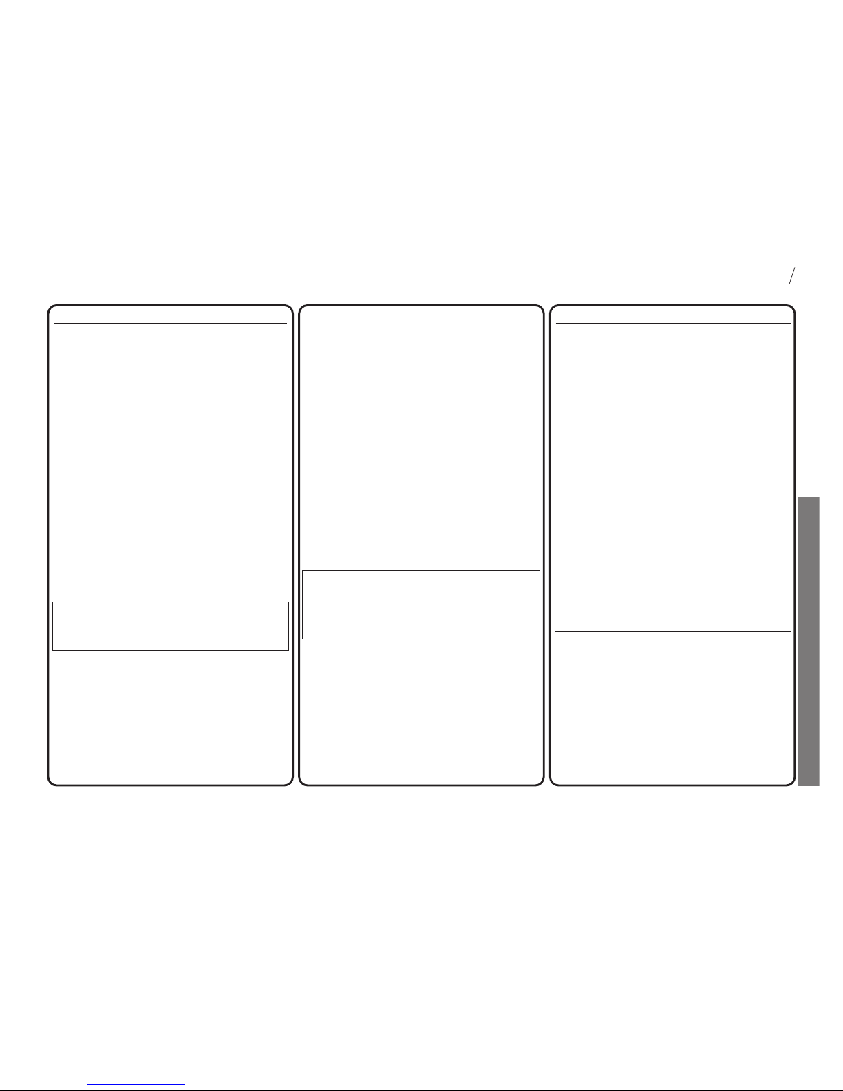
Tip
Ring
Sleeve
Balanced XLR
Unbalanced
Jack
Tip
Sleeve
Tip
Sleeve
Synth
Guitar
1
2
3
1
2
3
Microphone
Synth or Guitar
Output
Digital Output Option
(see separate documentation for connection guidance)
Unbalanced Jack
Tip
Sleeve
Tip
Sleeve
Balanced Jack
Tip
Ring
Sleeve
Tip
Ring
Sleeve
Synth Mixing Console
From Synth output
From Mixer output or
Insert Send
Tip
Sleeve
Tip
Sleeve
Unbalanced Jack
To Line I/P, Tape I/P
or Mixer Insert
Return
Balanced Jack
Tip
Ring
Sleeve
Tip
Ring
Sleeve
Mixing Console
Tape Machine/Hard Disc Recorder
Page 5
5
INTRODUCTION TO THE TRAKMASTER
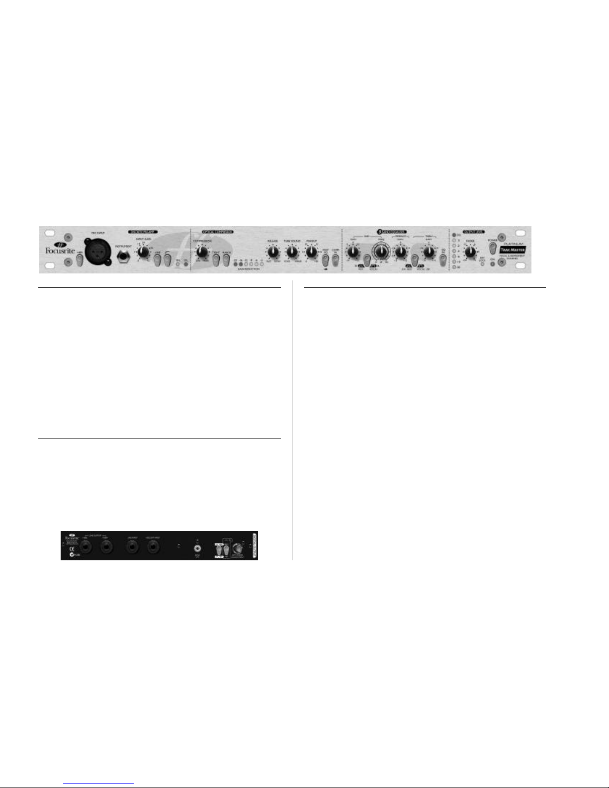
The TrakMaster is an analogue mono channel strip, with an optional 24-bit/96 kHz high
quality digital output. It combines a range of tools in one compact unit, providing the
project studio engineer, producer or musician with the perfect analogue solution for
recording and mixing a wide range of instruments.
The TrakMaster comprises a discrete transistor Class A microphone preamplifier, balanced
line input, direct instrument input, optical compressor and 3-band equaliser. There is also
an optional 24-bit/96 kHz high quality digital output. When recording, you don’t
necessarily need to route your signal through your mixing console; simply connect a
microphone or instrument to the appropriate input on the TrakMaster, and feed its output
directly into your recorder (such as a PC soundcard, hard disk recorder, DAT machine or
other tape machine). This will ensure you record the cleanest signal at the highest quality,
since it removes the possibility of noise or distortion being added to the signal by a mixer.
The easiest way to learn how to use the TrakMaster, particularly if you are unfamiliar with
the principles of its individual processing sections, is to try each control in turn. Finally, try
them all together to enjoy the full creative potential of your TrakMaster!
REAR PANEL CONNECTIONS AND SWITCHES
The TrakMaster features a line level input on a balanced (+4 dBu) TRS jack. This input
can also take an unbalanced (-10 dBV) jack connector. There are two line level outputs,
both on TRS jacks. One of these outputs is balanced (+4 dBu), and is suitable for use with
professional equipment with balanced inputs, such as professional mixing consoles and
recorders; the other is unbalanced (-10 dBV), to match semi-professional or consumer
mixers, recorders and soundcards. These outputs can be used simultaneously, so that it’s
possible to monitor the signal being sent to the recorder with zero latency – an important
concern in computer-based recording systems. For more information on unbalanced and
balanced connections please see the Frequently Asked Questions section on page 13.
GETTING STARTED
SETTING UP THE UNIT FOR RECORDING
• Ensure that nothing other than the mains supply is connected to your TrakMaster,
then switch it on via the POWER switch on the right hand side of the unit.
• Connect the line output of the TrakMaster to your recorder, via a balanced (TRS) or
unbalanced 1/4” jack connector, choosing +4 dBu or –10 dBV to match the input
levels on your recorder or soundcard. If you are unsure of which level is required,
refer to the user guide of your recording device.
• Ensure that the LINE switch is disengaged if you are recording a source connected to
the MIC INPUT or INSTRUMENT input. If recording a line level source
connected to the rear panel LINE INPUT, ensure the LINE switch is engaged.
• Ensure that INPUT GAIN and FADER are set fully anti-clockwise.
• Connect a microphone to MIC INPUT on front panel via an XLR cable, or an
electric guitar or bass to the INSTRUMENT input via a 1/4” jack. If you wish to
record a line-level source, connect it to the rear panel LINE INPUT using a balanced
(TRS) or unbalanced 1/4” jack.
• If using a microphone that requires phantom power, switch +48V in. If you are
unsure whether your microphone requires this phantom power, refer to its user guide,
as phantom power may damage some microphones.
• Increase the INPUT GAIN control, ensuring that the green SIG LED is always
illuminated, and that the red O/L LED does not illuminate when the loudest signal is
present.
• If using a micrphone, ensure that the microphone placement is correct. Before you
start recording, listen to the sound from the microphone with all parts of the
TrakMaster switched out (IN buttons not lit), and alter the microphone placement
until you get close to the sound you want. Note that moving the microphone may
have an effect on the level of the signal entering the TrakMaster, requiring an
alteration to the gain setting.
• If required, add compression using the OPTICAL COMPRESSOR, ensuring that
you use the MAKEUP gain control to restore the maximum volume to its original
level. When setting compression, it is better to apply too little than too much. Have
the COMPRESSION control quite low and do not use the TIGHT function. If you
are looking for a classic analogue tape or valve sound, use the TUBE SOUND
control.
Page 6
6
• If necessary, use the 3-BAND EQUALISER to set the desired tonal quality.
• Use the FADER to set the final output level (see instructions in Facilities And
Controls section of this manual.)
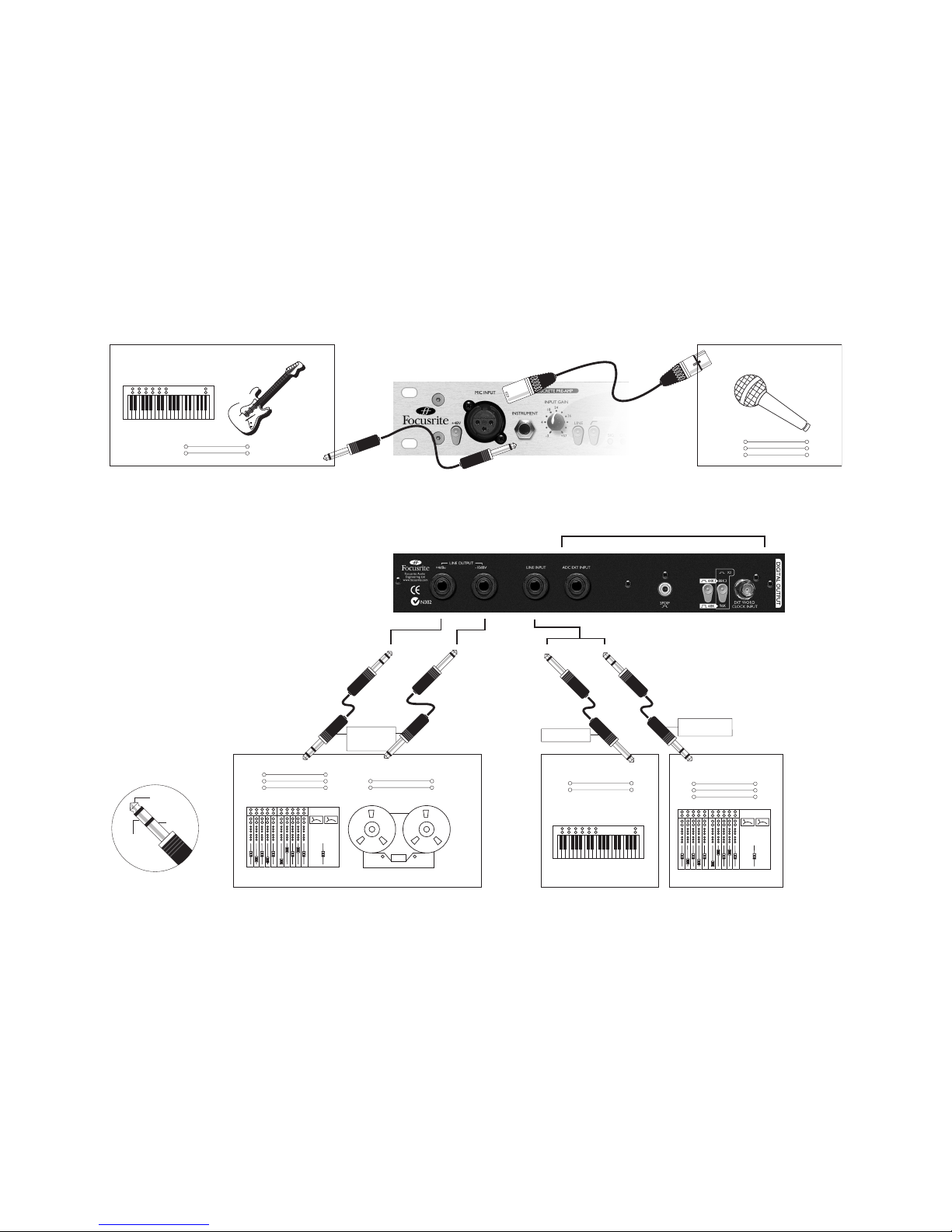
FACILITIES AND CONTROLS
POWER – turns the unit on and illuminates the blue LED directly below it. We
recommend that the unit be powered up before connecting to any other equipment that it
is feeding, to avoid clicks or thumps which may harm output devices. It is best to allow the
unit to stabilise for a couple of minutes before use to ensure that the internal circuitry is
properly initialised.
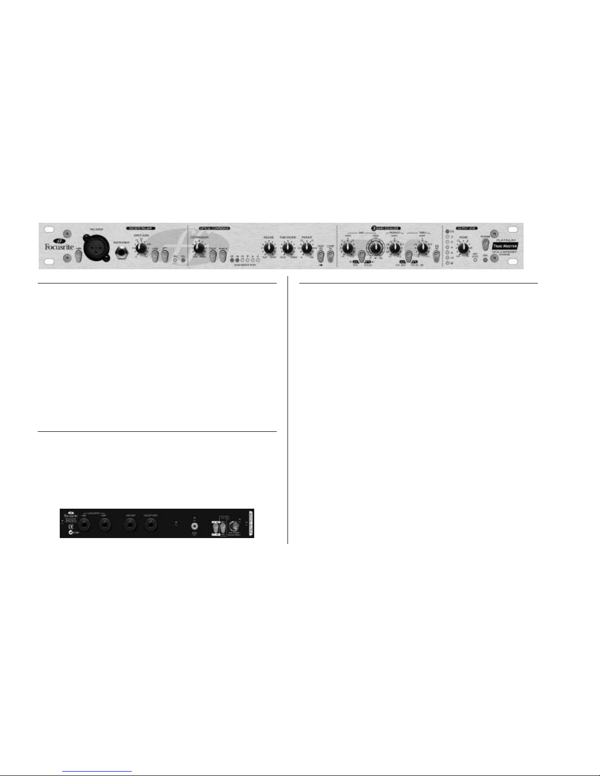
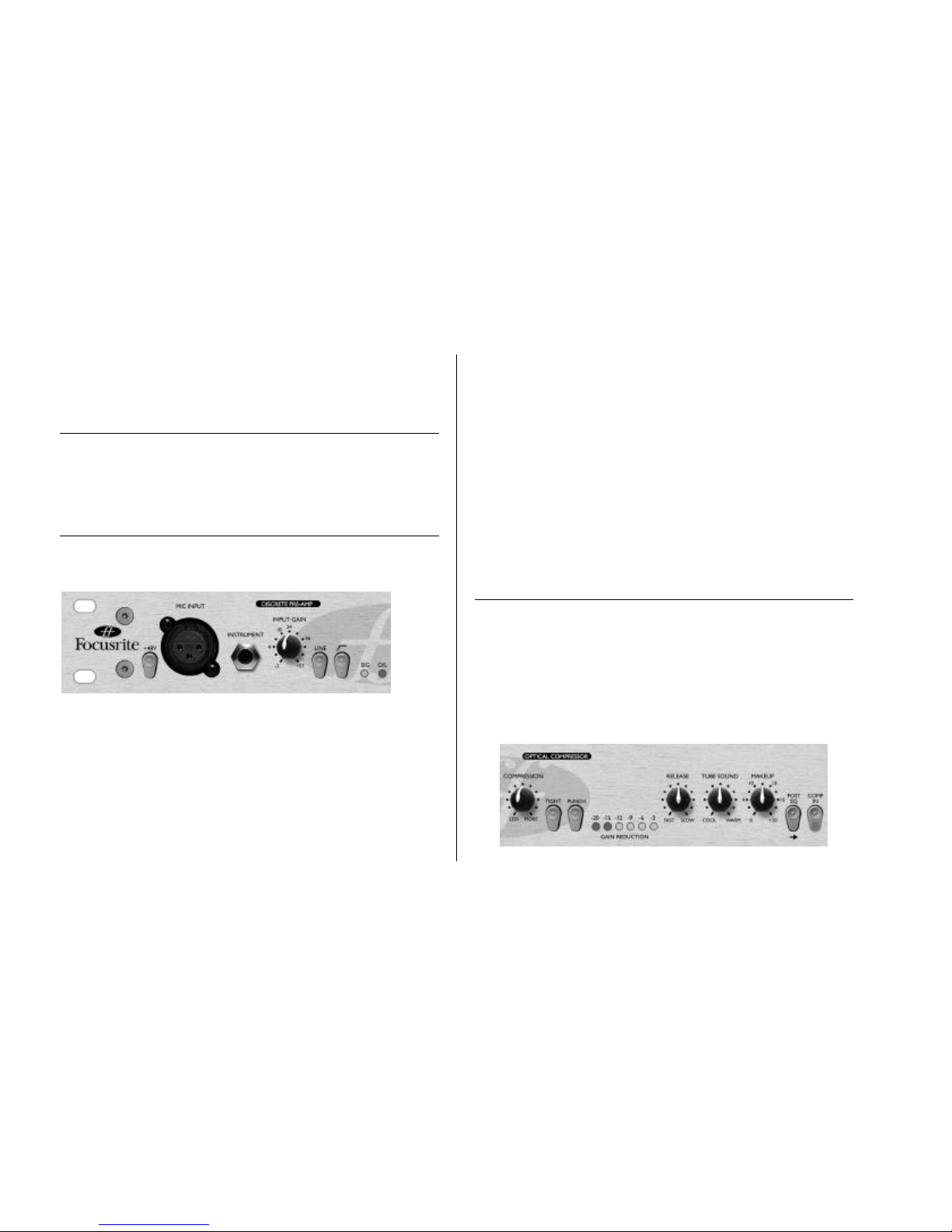
DISCRETE PRE-AMP
This part of the unit is a discrete transistor preamplifier, for matching the level of a choice
of incoming signals to the internal working level of the OPTICAL COMPRESSOR and
3-BAND EQUALISER stages that follow.
+48V switch – This provides +48V of phantom power for condenser microphones
when engaged. This switch affects the MIC INPUT only. If you are unsure whether your
microphone requires phantom power, refer to its user guide before connecting, as it is
possible to damage some microphones by providing them with phantom power.
MIC INPUT– This is an XLR input to be used with a microphone. This input is only
active when the LINE switch is disengaged. Inserting a 1/4” jack in the INSTRUMENT
INPUT automatically cuts the MIC INPUT signal.
INSTRUMENT – This is a high impedance 1/4” jack input that allows you to
connect an electric guitar or bass guitar to the unit without loading the pickups, and
without the need for a DI box. A synth with a low output level may also be connected
here. This input only functions when the LINE switch is disengaged.
INPUT GAIN – This sets the level of the incoming signal from the selected input.
Connect an input signal to the unit, ensuring that the INPUT GAIN control is set fully
anti-clockwise, and increase the INPUT GAIN so that the green SIG LED is always
illuminated when there is a signal present. The red O/L (Overload) LED may light
occasionally, but only if the input signal gets particularly loud. If the O/L LED stays on
continuously for any period, or you hear the unit distort during loud peaks, you should
reduce the INPUT GAIN.
LINE switch – When engaged, this selects the rear LINE INPUT, instead of the front
panel inputs (MIC INPUT and INSTRUMENT.) When disengaged, the front panel
inputs are selected. If a microphone and instrument are connected simultaneously, the
INSTRUMENT input will override the MIC INPUT.
HPF ( ) switch – This is a high-pass filter, which removes unwanted low
frequencies such as rumble from microphone stands, or ‘proximity effect’ (where low
frequencies are over-emphasised when using certain types of microphone at close
distances.) This switch affects the MIC INPUT only.
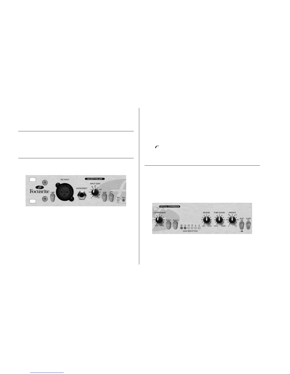
OPTICAL COMPRESSOR
The TrakMaster’s compressor uses opto-based technology, which gives more pleasant
distortion characteristics and faster response than low-cost, VCA-based compressors. The
optical compressor acts like an automatic volume control, turning down the volume of a
signal if it gets too loud. It reduces variation between loud and quiet passages, as it
automatically reduces the gain when the signal rises above a certain volume (the
‘threshold’). Therefore, it tends to even out a performance, stopping the instrument from
leaping out of the mix, or disappearing into it. Compression can also make things sound
louder, without actually increasing the peak level. (For more information on compression,
refer to the Beginner’s Guide to Compression on page 11)
COMPRESSION – This sets the volume level, or ‘threshold’, at which compression
begins, affecting how much of the signal is being compressed. Turning the
COMPRESSION control clockwise increases the amount of the signal that the compressor
affects – giving more compression. Turning the control anti-clockwise decreases the
amount of the signal that the compressor affects – giving less compression.
TIGHT switch – This switch gives a harder compression ‘ratio’ (6:1) when engaged.
This means that the level of signals exceeding the ‘threshold’ will be even further reduced.
Page 7
7
This switch should be used when you want the compressor to keep the volume of an
instrument at a very consistent level throughout its performance, and is best suited to
sources such as guitars, bass guitars and drums. When the switch is disengaged, a softer
compression ‘ratio’ (3:1) is used. This will keep more of the contrasts in volume of the
original performance. This approach may be more suitable for vocals.
PUNCH switch – The speed with which a compressor reacts to signals louder than
the ‘threshold’ volume alters the way the compressor sounds. If the compressor reacts
quickly, the attack of a note might sound squashed. Sometimes this is desirable, but if the
time taken for the compressor to react is increased, the attack of each note isn’t squashed as
much, therefore making the compressed signal sound ‘punchier’. Use this function to
restore punch that is lost due to compression.
GAIN REDUCTION meter – Before MAKEUP gain is applied (see below), the
compressor reduces the volume of loud signals. The GAIN REDUCTION meter shows
how many dB of gain reduction the compressor is causing. The more gain reduction, the
more heavily you are compressing. This meter is also a useful guide to how much
MAKEUP gain will be required in order to restore the original signal volume.
RELEASE – This determines how quickly compression dies away once the volume of
the source signal has fallen below the ‘threshold’ at which the compressor reacts. When in
the anti-clockwise position, compression is released very quickly, which may be appropriate
for signals that vary rapidly in volume, as this allows the compressor to recover before beats
that follow. However, a short release time can lead to distortion on more sustained
material. Slower release times give a smoother effect, and may result in audible ‘pumping’,
which may help a piece of music sound more exciting, but may not always be appropriate.
Increasing the RELEASE control introduces a programme-dependent slower release time.
TUBE SOUND – The TrakMaster contains circuitry that simulates the warmth
normally associated with tube or tape distortion. The TUBE SOUND control allows you
to add as much of this warmth as you like. This control is especially useful for adding
character when recording onto a digital medium.
MAKEUP – Since compressing a signal makes loud parts quieter, the maximum volume
of the performance will now be lower than it was before being compressed. Therefore, it is
necessary to restore the maximum volume level back to its original value. Note that this has
the effect of making quiet elements louder, raising the perceived overall volume level of the
signal.
To set the MAKEUP gain correctly, switch the OPTICAL COMPRESSOR in and out
whilst slowly increasing the MAKEUP control from its anti-clockwise position. The
MAKEUP gain will be set correctly when the peak reading on the OUTPUT LEVEL
meter (on the far right of the unit) reads the same whether the OPTICAL
COMPRESSOR is switched in or out. The compressed signal should sound slightly louder
than the uncompressed signal.
POST EQ switch – When engaged, this switch causes the OPTICAL
COMPRESSOR section to process the signal after the 3-BAND EQUALISER section.
This is useful because boosting or cutting frequencies in the 3-BAND EQUALISER
section will alter the signal that the OPTICAL COMPRESSOR reacts to.
For example: a very bass-heavy guitar is compressed, then EQed. The low frequencies will
exceed the threshold and cause compression of the whole signal. If the EQ is applied first,
and some of the low frequencies are attenuated, the compressor will not respond to these
low frequencies so much.
COMP IN switch – When engaged, this illumintaed switch makes the OPTICAL
COMPRESSOR section of the TrakMaster active. To bypass this section, leave the switch
disengaged.
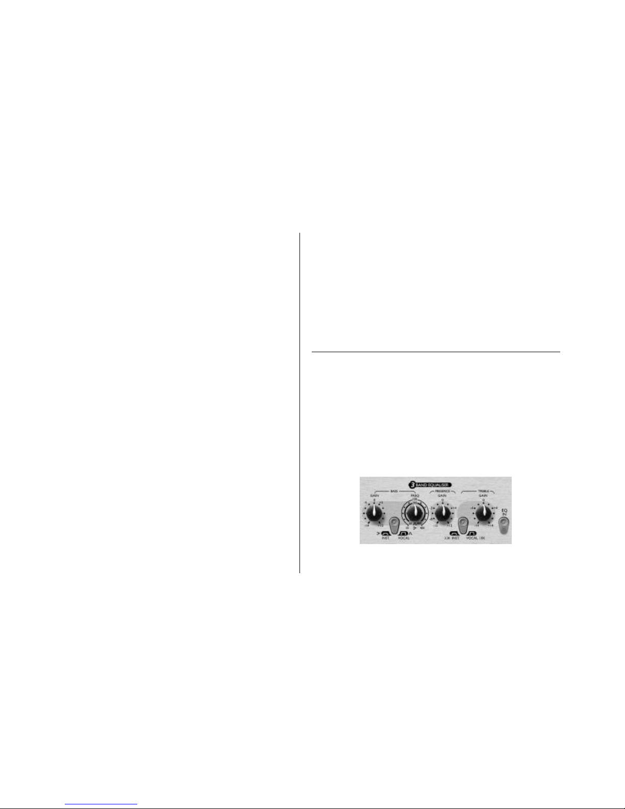
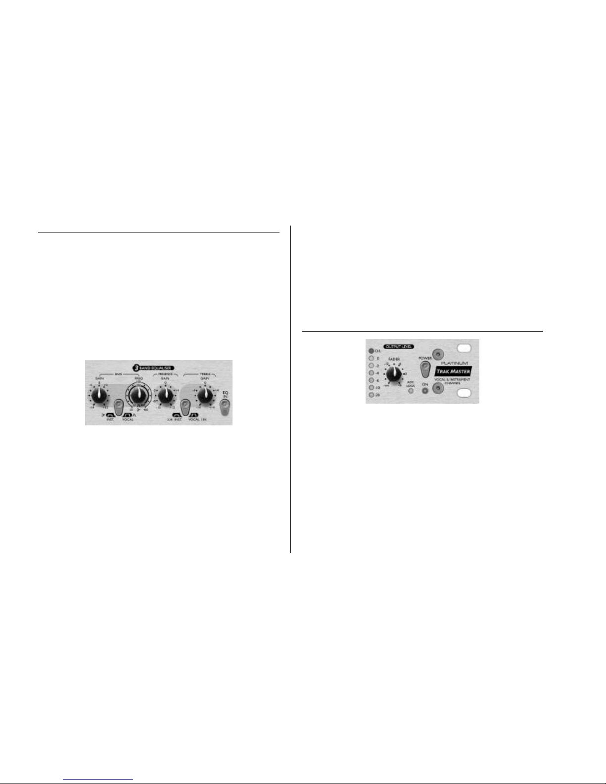
3-BAND EQUALISER
The 3-BAND EQUALISER (or ‘EQ’, as it is more commonly known) section of the
TrakMaster allows you to cut or boost certain frequencies. The TrakMaster EQ is
particularly versatile because the BASS and TREBLE bands can each be switched between
VOCAL and INSTRUMENT modes, giving a choice of voice-optimised EQ (with bellshaped sweepable low mid band and 10 kHz shelving high frequency band) or instrument
EQ (with shelving sweepable low frequency band and 3 kHz shelving high frequency
band.)
The use of EQ can be either ‘creative’ or ‘corrective’. ‘Creative’ use of EQ is when it is
used to enhance the sound – usually by boosting desirable frequencies (although this is not
always the case.) ‘Corrective’ use of EQ is when it is used to remove some unwanted sound
or unpleasant frequency – usually by attenuating the offending frequency ranges. It is
always a good policy to get as natural a recorded sound as possible from the source before
any processing (compression or EQ) is applied. This will make the application of any future
processing much easier and more natural sounding.
BASS GAIN – This allows you to cut or boost frequencies below or around the
frequency selected by the FREQ control, depending on which mode has been selected by
the INST/VOCAL switch. The control offers up to 12 dB of boost and up to 14 dB of cut.
Page 8
8
BASS INST/VOCAL switch – When this switch is engaged (INST mode), the
BASS controls act as a low frequency shelving EQ. When disengaged (VOCAL mode), the
BASS control acts as a low-mid band parametric EQ. (See the Guide To Equalisation onm
page 13 for more information on these terms.)
BASS FREQ – This control allows you to select which frequency you want the
BASS GAIN control to cut or boost from. In INST mode, the FREQ control selects values
in the range 25-400 Hz. In VOCAL mode, the FREQ control selects values in the range
50-800 Hz.
PRESENCE – This allows you to cut or boost hi mid frequencies (1.5 kHz). It offers
up to 12 dB of boost and 15 dB of cut. Boosting these hi mid frequencies adds presence to
the signal, allowing sounds to cut through the mix.
TREBLE GAIN - This shelving EQ allows you to cut or boost high frequencies by
+/- 14 dB. The frequency is switchable between two values using the INST/VOCAL
switch.
TREBLE INST/VOCAL switch – When this switch is engaged (INST mode),
the TREBLE GAIN control operates on frequencies above 3.3 kHz. When disengaged
(VOCAL mode), the TREBLE GAIN control operates on frequencies above 10 kHz.
EQ IN switch – When engaged, this illuminated switch makes the 3-BAND
EQUALISER section of the TrakMaster active. To bypass this section, leave the switch
disengaged.
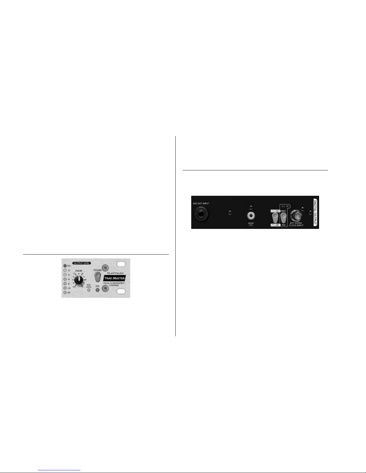
OUTPUT LEVEL
OUTPUT LEVEL meter – This meter shows the level of the signal leaving the
TrakMaster. You should aim for the meter to peak at the 0 LED, without illuminating the
O/L (overload) LED. It is especially important not to overload the output when using the
optional digital output, as this will cause severe and unpleasant distortion, even if
overloading is brief.
FADER - This is used to match the output volume level from the TrakMaster to the
input level of the next unit in the chain (e.g. sound card, hard disk recorder, tape machine,
mixer etc.) When setting the output level, always start with this control set fully anticlockwise and increase the output level until you reach the correct level – do not start with
the FADER set high, as it may damage the next unit in the chain.
If inserting the TrakMaster into a channel of a mixing console, set the FADER at 0
(roughly its 3 o’clock position), and adjust the levels using the console.
DIGITAL OUTPUT
In addition to the analogue outputs, a high quality 24 bit, 128 times oversampled digital
output may be fitted as an option, which can operate at sample frequencies of 44.1, 48,
88.2 or 96 kHz. All of the following functions are available on the rear panel when this
option is fitted:
ADC EXT INPUT (rear panel) – This line level input on the rear panel allows
an additional signal to be routed through the spare channel of the stereo digital output.
SPDIF OUTPUT - This 24 bit output is SPDIF format on an RCA phono
connector. If 16 bit resolution is required, the receiving device should dither the 24 bit
signal to achieve 16 bit performance.
SAMPLE FREQUENCY - Two switches give a choice of four sample frequencies
as marked on the rear panel. The left hand switch selects between 44.1kHz (switch out)
and 48kHz (switch in), and the right hand switch doubles the selected frequency.
EXTERNAL WORDCLOCK - If an external wordclock source is fed to the BNC
connector, the TrakMaster will attempt to synchronise to it. When the unit is correctly
locked to the external clock source the ADC LOCK LED (on the front panel) will light to
indicate correct operation. In this case the ADC LOCK LED should be continuously lit. If
this flickers it indicates bad jitter on the synchronising signal which would need
investigation of the wordclock generating device.
Page 9

9
OBTAINING A GOOD QUALITY VOCAL SOUND
MICROPHONE POSITIONING
For a natural sound without pops, position the microphone at a distance of about 1 metre
from the singer. Recording vocals requires a different technique to that used when singing
on stage, where the vocalist usually sings with the microphone touching his or her lips, so
your vocalist may find it difficult to perform a long way from the mic. If this affects the
performance (or if the vocal sounds weak), allow the vocalist move closer, but use a pop
shield on the mic. It may also be necessary to use the High Pass Filter ( ) in the Discrete
Transistor Input section to remove excessive bass caused by this technique.
USING THE OPTICAL COMPRESSOR
If the vocalist is having difficulty staying a consistent distance from the microphone, the
recorded performance will get softer and louder as the distance from the mic varies. The
vocalist may also vary the volume of their performance to such an extent that when they
are singing loudly, the vocal is far too dominant, and when they are singing quietly, the
vocal is lost in the mix. To even out these variations, use the OPTICAL COMPRESSOR
set as follows:
• COMPRESSION set around 9 o’clock
• TIGHT and PUNCH switches disengaged
• RELEASE set around 12 o’clock
• TUBE SOUND set fully anticlockwise
• MAKEUP set around the ‘4’ position
Depending on the variations in the vocalist’s volume level, you may need to increase the
COMPRESSION control until the vocal level sounds more consistent.
If the vocalist’s performance is very ‘dynamic’ (going from soft to very loud, as described
earlier), try setting the OPTICAL COMPRESSOR as follows:
• COMPRESSION set around 12 o’clock
• TIGHT switch engaged
• PUNCH switch disengaged
• RELEASE set around 12 o’clock
• TUBE SOUND set fully anticlockwise
• MAKEUP set around the ‘10’ position
Compression avoids overloading the input to the 3-BAND EQUALISER during loud parts
of the performance. The RELEASE time is set as short as possible, to avoid compressing
the quiet parts of the performance.
SPOKEN WORD
When recording the spoken word, use the BASS control to boost the low frequency areas
with the INST/VOCAL switch set to the VOCAL position. As voices differ in pitch,
adjust the FREQ control until you get a deep, resonant and powerful-sounding voice. This
is the sort of effect used by radio DJs.
BACKING VOCALS
Backing vocals are normally heavily compressed, since you want them to have a continuous
presence without volume variations. Set the OPTICAL COMPRESSOR as follows:
• COMPRESSION set around 3 o’clock
• TIGHT switch engaged
• PUNCH switch disengaged
• RELEASE set around 12 o’clock
• TUBE SOUND set fully anticlockwise
• MAKEUP set around the ‘13’ position
To stop the backing vocals sounding too ‘fat’ and overpowering, reduce the bass with the
BASS control, ensuring that the INST/VOCAL switch is set to the VOCAL position.
Also, use the TREBLE control (with the INST/VOCAL switch in the VOCAL position)
to boost the higher frequencies.
OBTAINING A GOOD QUALITY ELECTRIC GUITAR
SOUND
USING THE 3-BAND EQUALISER
With a guitar plugged into the instrument input, you should get a great sound straight
away. Use the 3-BAND EQUALISER to get the sound you want; in particular:
• Set the INST/VOCAL switch is set to the INST position. Then, using the BASS control
to boost frequencies below 250 Hz, you can add more ‘body’ to the sound.
• Boosting the PRESENCE control should give more ‘bite’ to the guitar sound.
• When cutting the BASS and TREBLE controls, and boosting the PRESENCE
control, a ‘lo-fi’ guitar sound can be achieved. This effect works well when there are
two or more guitars, only one of which is being treated in this way.
Page 10

10
USING THE OPTICAL COMPRESSOR
It is normally a good idea to add compression to an electric guitar. This will even out
inconsistencies in volume, helping it to sit nicely in the track. Compression will also have
the effect of adding more sustain to a guitar. Try starting with the OPTICAL
COMPRESSOR set as follows:
• COMPRESSION set around 12 o’clock
• TIGHT switch engaged
• PUNCH switch engaged
• RELEASE set around 3 o’clock
• TUBE SOUND set as desired
• MAKEUP set around the ‘10’ position
ADDING EFFECTS USING FOOT PEDALS
Plug all foot pedals between the guitar and the TrakMaster. Put the OPTICAL
COMPRESSOR in bypass (switch disengaged) and use the 3-BAND EQUALISER to set
the tone you want, then switch in the effects you want to use. If necessary, use the 3BAND EQUALISER to modify the tone after the effects have been added.
RECORDING ELECTRIC BASS
Since it is normally desirable for the bass to stay at a consistent volume in the rhythm track,
it is common to add a quite a lot of compression. Set the OPTICAL COMPRESSOR as
follows:
• COMPRESSION set around 12 o’clock
• TIGHT switch engaged
• PUNCH switch engaged
• RELEASE set around 3 o’clock
• TUBE SOUND set as desired
• MAKEUP set around the ‘10’ position
Try experimenting with the RELEASE control and the TIGHT switch to get the sound
you want. If you want a punchier bass sound, engage the PUNCH switch. If you want a
more rounded bass sound, leave the PUNCH switch disengaged. For a funky sound when
slapping, set the COMPRESSION control quite high, engage the TIGHT switch, and
leave the PUNCH switch disengaged.
Use the BASS control (in INST mode) to give the bass guitar more depth. The FREQ
control should sound best when set between 60 Hz and 150 Hz. Use the PRESENCE
control to add more of the upper harmonic content that gives punch (or the ‘click’ sound
when using a plectrum.)
IMPROVING SOUND QUALITY USING THE 3-BAND
EQUALISER
The TrakMaster’s equalisation section is extremely versatile. The choice of VOCAL and
INST modes for both the low frequency and high frequency bands ensures that no matter
what kind of material you’re processing, the EQ can do exactly what you need it to do.
You can use the 3-BAND EQUALISER to fix the following problems:
Muddy: Use the BASS control to reduce some of the low frequencies. Solo the track, set
the BASS control to full cut, and adjust the FREQ (in either INST or VOCAL modes)
until the sound is more balanced. Then listen to the track in context with the rest if the
mix, and adjust the amount of cut on the BASS control to give the correct sound in
context. If necessary you may also need to increase the amount of TREBLE (in VOCAL
mode if dealing with vocals).
Flat: Increase the PRESENCE control. You may need to increase the amount of TREBLE
(in VOCAL mode if dealing with vocals), and then some BASS if the result has too much
top end. However, beware of overdoing this effect by adding too much.
Harsh: Use the PRESENCE control to reduce the strength of these frequencies. You may
also want to add some BASS, and if necessary, reduce some TREBLE.
Lost in the mix: Increase the PRESENCE control. Avoid using too much BASS as you
will be boosting frequencies in the same range as other instruments on the track.
MIXING DOWN
When mixing down the final multitrack recording of your song, the TrakMaster can be
connected in one of two ways:
Connect the selected output channel of your recorder to the line input of the TrakMaster,
and connect the line output of your TrakMaster to the selected line input of your mixer.
Use the insert point on the channel strip of your mixing board to insert the TrakMaster
using its line input and output.
Don’t be afraid to be outrageous when mixing down. For example, don’t always try to
make the vocal sound natural, since one that stands out in the mix is often heavily effected.
In pop music, the vocal is invariably heavily compressed, and has equalisation added. In the
OPTICAL COMPRESSOR section, try using the TUBE SOUND control to give an
analogue tape/tube sound.
Page 11
11
A BEGINNER’S GUIDE TO COMPRESSION
Compressors are probably the most widely used signal processors in the audio industry. A
compressor can be thought of as an automatic volume control. Once the volume of the
input signal exceeds a certain level (called the threshold), the compressor reduces the gain
(or, in other words, ‘turns the volume down’), causing the signal to be less loud than it
would otherwise have been.
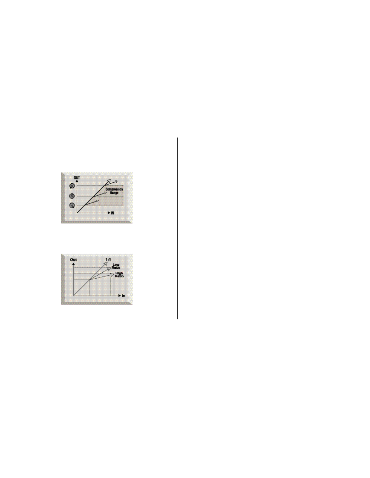
The amount by which the compressor reduces the gain is determined by the ratio. The
ratio is conventionally expressed as a numerical value, e.g. ‘4:1’, which represents the
amount by which the gain is reduced when the volume of the signal rises above the
threshold. This is based on dB - if a ratio of 4:1 is set, an input signal exceeding the
threshold by 4 dB will cause only a 1 dB increase in level at the output.
Compression has the result that any variations in the volume of the signal (in other words,
the signal’s dynamic range – the difference between the minimum and maximum levels
of a signal) are reduced. The amount of this reduction is determined by the threshold (the
level above which the gain is reduced) and the ratio (the amount by which the gain is
reduced.) Higher ratios are referred to as hard ratios; lower ratios are called soft ratios.
Because compression causes a reduction in volume level of loud signals, gain must be
applied after the compressor to bring the overall volume level back up, so that the
maximum volume before the compressor is the same as that after the compressor. This is
called makeup gain, and is necessary so that the maximum level of the signal is always the
same, for correct level matching with any further processing or other equipment.
Once makeup gain has been applied, the quieter parts of the signal that were lower than the
threshold volume (and hence not compressed) will now be louder than they were before
entering the compressor. This will cause any compressed instrument to sound louder. One
use for this phenomenon is to give guitars more sustain.
In most pop music, the backing instruments (such as drums, bass guitars, rhythm guitars etc)
tend to be compressed heavily (using a fairly hard ratio and low threshold), so that they
remain at a consistent volume level throughout the track. This will provide a solid backing,
without occasional drum hits or bass notes poking through (or disappearing from) the mix
untidily.
A soft ratio tends to be used on instruments such as lead guitars or vocals that ‘sit’ on top of
the mix. In this situation it is desirable to preserve more of the dynamics of the original
performance, to retain more expression. A reduction in variation of volume level is still
required (for the reasons mentioned above), but not to the same extent.
Here’s an example of the effects of threshold, ratio and makeup gain using some real
numbers. Suppose the threshold of the compressor is set to –10 dB and the ratio is set to
4:1. An input signal with a peak at –6 dB (4 dB above the threshold) would be output from
the compressor with a peak at –9 dB (1 dB above the threshold).
Signal levels below the threshold are unaffected, so if the level of the signal in the above
example varied between –20 dB and –6 dB before entering the compressor, it will vary
between –20 and –9 dB after being compressed. In other words its dynamic range (the
difference between the quietest and loudest parts of the signal in dB) is reduced from 14 dB
to 11 dB. Following this compression, 3 dB of makeup gain would be applied to bring
the peak back up to –6 dB. Note that this will bring the minimum signal level up from –20
dB to –17 dB, and so the perceived loudness of the signal will thus be increased, although
the peak will still be at –6 dB.
Page 12
12
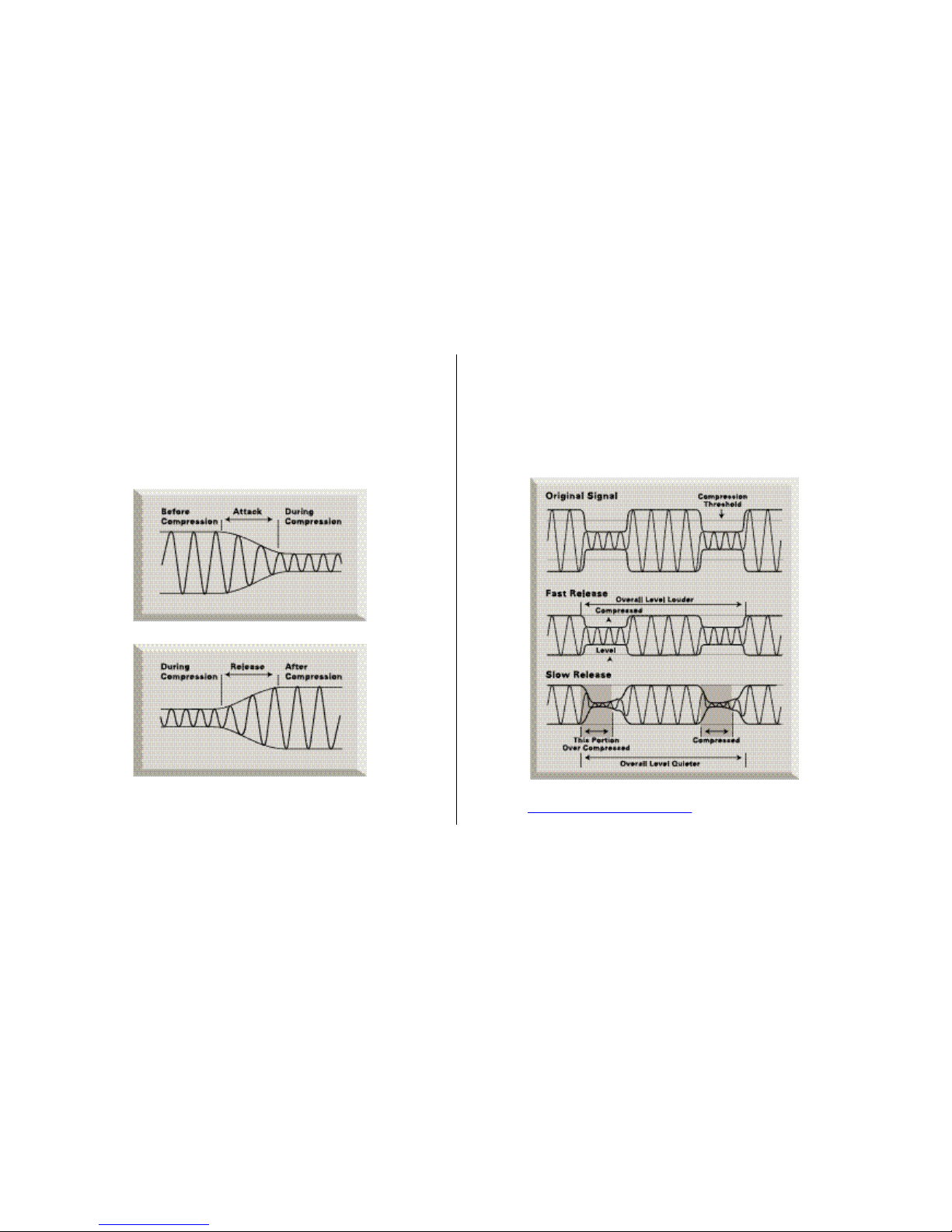
The other controls included on most compressors are attack and release.
Attack determines the speed at which the compressor starts to reduce the gain once the
threshold has been exceeded. Think of it as the time taken to turn the volume down. Very
short attack times mean the compressor ‘kicks in’ very quickly – short attack times are
typically used for vocals in order to keep the levels under strict control. Longer attack times
mean more of the original signal’s attack dynamics are preserved – this is a good way of
keeping percussive and guitar sounds exciting and punchy.
Release determines the speed at which the compressor stops acting once the signal drops
below the threshold. Think of it as the time taken to turn the volume back up.
Short release times mean the compressor very quickly returns the signal to its normal level.
This can produce a ‘pumping’ sound, where the changes in volume are very audible.
Depending on the style of music, this can be undesirable, or a useful creative effect. Longer
release times may mean that parts of the signal below the threshold end up being
compressed, or that the gain doesn’t have a chance to return to normal before the next
‘above threshold’ sound – remember that the compressor works on the whole signal. See
the diagram below:
Check out http://www.focusrite.com/features for links to more information on
the subject of compression.
Page 13

13
A BEGINNER’S GUIDE TO EQUALISATION
Equalisers are also widely used in the audio industry, and are effectively just tone
controllers, though a bit more involved than those found on most hi-fi systems. They allow
you to cut or boost certain frequencies or frequency bands within the audio signal.
There are two main applications for using equalisation, or EQ (as it’s more commonly
known). The first is ‘creative’ use. This involves enhancing a sound that is already present
in some desirable way. Typical examples might involve boosting lower frequencies to give
more depth, or boosting the high frequencies to give more of a ‘sparkle’ to a sound.
Because the precise frequencies that give these qualities will vary from instrument to
instrument, it is sometimes necessary to be able to adjust the point at which frequencies will
be cut or boosted by the EQ, as well as the amount of cut or boost.
The other main application of EQ is ‘corrective’ use. This involves using EQ to remove or
reduce the level of unwanted frequencies. Here are a few examples of ‘corrective’ use of
EQ:
• Cutting low frequencies to reduce ‘proximity effect’, where low frequencies have been
over-emphasised as a result of close miking with certain types of microphone.
• Cutting the frequencies that may cause a vocal to sound boxy, nasal or harsh.
• Cutting the frequencies that may cause a drum to ring undesirably.
EQ exists in various forms. The TrakMaster offers two sorts of EQ: ‘shelving’ and
‘parametric’ (see Facilities And Controls for more details). Shelving EQ boosts or cuts all
frequencies above or below a specific frequency. Low shelving EQ boosts or cuts all
frequencies below a certain frequency, whereas high shelving EQ boosts or cuts all
frequencies above a certain frequency.
Parametric EQ allows the user to focus in on a specific band of frequencies in order to cut
or boost them. This is particularly useful for ‘corrective’ applications of EQ as the offending
frequency may be honed in on, and its gain reduced. It is also useful for ‘creative’
applications, for example giving presence to a vocal.
Check out http://www.focusrite.com/features for links to more information on
the subject of EQ.
FREQUENTLY ASKED QUESTIONS
Q. My TrakMaster gets quite hot when in use. Should I be worried about this?
A. No. This is a result of the high-quality Class A circuitry inside your TrakMaster and
should not be a problem. As a precaution, it is wise to rack hotter units lower down your
rack than cooler units (see next FAQ). If space is available, fit a blank panel between units
to allow extra ventilation.
Q. Where in my rack should I put my TrakMaster?
A. It is generally a good idea to place hotter units lower down your rack. This is because
the air that is heated from each unit in the rack will rise to the top of the rack, placing the
uppermost units in a hotter environment. Therefore, a hot unit at the top of a rack will get
even hotter.
Q. What is the difference between +4 dBu and –10 dBV?
A. These are different signal operating levels. +4 dBu usually refers to professional
equipment and –10 dBV usually refers to semi-professional or consumer equipment. It is
important to make sure that any two or more devices connected to each other are
operating at the same signal level. The +4 dBu/-10 dBV switches on the rear of the
TrakMaster allow you to use the TrakMaster’s outputs at either operating level.
If the +4 dBu output of a device feeds the –10 dBV input of another device, this may cause
the second device to overload. Alternatively, if the –10 dBV output of a device feeds the
+4 dBu input of another device, the second device may receive a signal level which is too
low (i.e. too quiet).
-10 dBV devices are usually connected using a mono 1/4” jack. This is known as an
‘unbalanced’ connection. +4dBu devices are usually connected using a TRS (stereo) 1/4”
jack, or XLRs. This is known as a ‘balanced’ connection.
Q. Should I use balanced connectors with my TrakMaster?
A. The TrakMaster may be run balanced or unbalanced, although it is best to use balanced
connectors where possible. If you want to connect your TrakMaster to a device with XLR
connectors, construct or purchase a cable that is wired as follows:
Page 14

14
TROUBLESHOOTING
No LEDs illuminate
• Is the POWER switched on?
• Is the voltage selector next to the mains connector on the rear of the unit set correctly?
If set incorrectly, the fuse may blow, requiring the correct fuse to be refitted and the
voltage to be correctly set.
No output when using the Line Input
• Is the POWER switched on?
• Is the LINE switch on the front panel switched in?
• Is the GAIN set correctly? (See ‘Facilities and Controls’ section for details.)
• Is the FADER set correctly? (See ‘Facilities and Controls’ section for details.)
No output when using the Mic Input
• Is the POWER switched on?
• Is the LINE switch on the front panel switched out?
• Is the GAIN set correctly? (See ‘Facilities and Controls’ section for details.)
• Is the FADER set correctly? (See ‘Facilities and Controls’ section for details.)
• Is there a jack inserted in the INSTRUMENT IP? If so, remove it.
• For microphones that require phantom power, is the +48V switch switched in? (if you
are unsure whether your microphone requires phantom power, check the user guide
for your microphone.)
No output when using the Instrument Input
• Is the POWER switched on?
• Is the LINE switch on the front panel switched out?
• Is the GAIN set correctly? (See ‘Facilities and Controls’ section for details.)
• Is the FADER set correctly? (See ‘Facilities and Controls’ section for details.)
The Optical Compressor is not working
• Is the IN (Compressor) switch engaged?
• Is the INPUT GAIN set correctly? If set too low, the signal level may not be high
enough to activate the compressor.
• Is the COMPRESSION control set correctly? (If set too low, the input level may not
reach the threshold at which compression starts.)
The 3-BAND EQUALISER is not working
• Is the EQ IN switch engaged?
CONTACTING US
If have any questions about your TrakMaster, or are continuing to have difficulty, email us
for help at tech@focusrite.com, phone us on +44 (0)1494 462246, or contact your local
distributor (see listing at the back of this manual).
Page 15
15
EINFÜHRUNG IN DEN TRAKMASTER
Der TrakMaster ist ein analoges Mono-Gerät mit einem optionalen hochwertigen 24Bit/96 kHz Digitalausgang. Der TrakMaster kombiniert mehrere Soundtools in einer
kompakten Einheit und bietet dem Projektstudio-Techniker, Produzenten oder Musiker
die perfekte analoge Lösung für das Aufnehmen und Mischen eines breiten Spektrums von
Instrumenten. Der TrakMaster verfügt über einen separaten Class A MikrofonTransistorvorverstärker, symmetrischen Line-Eingang, direkten Instrumenteneingang,
optischen Kompressor und 3-Band-EQ. Er bietet außerdem einen optionalen
hochwertigen 24-Bit/96 kHz Ausgang. Bei einer Aufnahme müssen Sie Ihr Signal nicht
unbedingt durch Ihr Mischpult leiten. Schließen Sie einfach ein Mikrofon oder Instrument
an den entsprechenden Eingang des TrakMasters an und leiten Sie dessen Ausgang direkt in
einen Recorder (z. B. eine PC Soundkarte, einen Hard Disk oder DAT Recorder oder
eine Bandmaschine). Auf diese Weise nehmen Sie das sauberste Signal mit der höchsten
Qualität auf, da dem Signal weder Rauschen noch Verzerrungen durch einen Mischer
hinzugefügt werden können. Die Bedienung des TrakMasters erlernen Sie am einfachsten besonders dann, wenn Sie mit den Grundlagen der einzelnen Bearbeitungssektionen nicht
vertraut sind -, indem Sie die verschiedenen Regler nacheinander ausprobieren. Danach
sollten Sie alle Regler zusammen einsetzen, um das ganze kreative Potential des
TrakMasters zu genießen!
RÜCKSEITIGE ANSCHLÜSSE UND SCHALTER
Der TrakMaster verfügt über einen Line Level-Eingang in Form einer symmetrischen (+4
dBu) TRS-Buchse. Dieser Eingang akzeptiert auch einen asymmetrischen (-10 dBV)
Stecker. Außerdem sind zwei Line Level-Ausgänge als TRS-Buchsen ausgelegt. Einer
dieser Ausgänge ist symmetrisch (+4 dBu) und kann mit den symmetrischen Eingängen
von Profi-Geräten, z. B. professionellen Mischpulten und Recordern, eingesetzt werden.
Der andere Ausgang ist asymmetrisch (-10 dBV) und an semi-professionelle Mischer,
Recorder und Soundkarten (Consumer-Klasse) angepasst. Die Ausgänge sind gleichzeitig
einsetzbar, so dass Sie das zum Recorder geleitete Signal ohne Verzögerung abhören
können - ein wichtiger Faktor bei computer-gestützten Aufnahmesystemen. Wegen
näherer Einzelheiten über asymmetrische und symmetrische Anschlüsse siehe FAQ-Sektion
auf Seite 24.
ERSTE SCHRITTE
GERÄT FÜR DIE AUFNAHME EINRICHTEN
• Achten Sie darauf, dass nur das Netzkabel an Ihren TrakMaster angeschlossen ist und
schalten Sie ihn dann mit dem POWER-Schalter auf der rechten Seite des Geräts ein.
• Verbinden Sie den Line-Ausgang des TrakMasters über einen symmetrischen (TRS)
oder einen asymmetrischen _“ Stecker mit Ihrem Recorder und wählen Sie +4 dBu
oder –10 dBV entsprechend dem Eingangspegel des Recorders oder der Soundkarte.
Wenn Sie den erforderlichen Pegel nicht kennen, schlagen Sie bitte im
Bedienungshandbuch Ihres Aufnahmegeräts nach.
• Wenn Sie eine an den MIC- oder INSTRUMENT-Eingang angeschlossene
Signalquelle aufnehmen, muss der LINE-Eingang mit dem LINE-Schalter deaktiviert
sein. Wenn Sie eine an den rückseitigen LINE-Eingang angeschlossene Signalquelle
mit Line-Pegel aufnehmen, muss der LINE-Eingang mit dem LINE-Schalter aktiviert
sein.
• Achten Sie darauf, dass INPUT GAIN und FADER ganz nach links gedreht sind.
• Schließen Sie ein Mikrofon über ein XLR-Kabel an den vorderseitigen MIC-Eingang
an. Oder schließen Sie eine E-Gitarre oder einen E-Bass über einen _“ Stecker an den
INSTRUMENT-Eingang an. Wenn Sie eine Signalquelle mit Line-Pegel aufzeichnen
möchten, schließen Sie diese über einen symmetrischen (TRS) oder einen
asymmetrischen _“ Stecker an den rückseitigen LINE-Eingang an.
• Falls das Mikrofon Phantomspannung benötigt, schalten Sie die +48V Option ein.
Wenn Sie nicht genau wissen, ob Ihr Mikrofon Phantomspannung benötigt, lesen Sie
bitte in dessen Bedienungshandbuch nach, da manche Mikrofone durch
Phantomspannung beschädigt werden können.
• Drehen Sie den INPUT GAIN-Regler auf und achten Sie darauf, dass die grüne SIG
LED immer leuchtet und die rote O/L LED auch bei den lautesten Signalen nicht
leuchtet.
• Achten Sie beim Mikrofon auf die richtige Positionierung. Bevor Sie mit der
Aufnahme beginnen, hören Sie sich den Klang des Mikrofons bei ausgeschalteten
TrakMaster-Funktionen (alle IN-Tasten erloschen) an und variieren Sie die MikrofonPosition, bis Sie den gewünschten Sound gefunden haben. Das Bewegen des
Mikrofons kann sich auf dessen Eingangspegel zum TrakMaster auswirken und ein
Nachregeln der Gain-Einstellung erfordern.
• Fügen Sie nötigenfalls mit dem OPTICAL COMPRESSOR etwas Kompression
hinzu und stellen Sie dann mit dem MAKEUP Gain-Regler die Maximallautstärke auf
ihren ursprünglichen Pegel ein. Verwenden Sie lieber zu wenig Kompression als zu
viel. Drehen Sie den COMPRESSION-Regler nur etwas auf und setzen Sie die
Page 16
16
TIGHT-Funktion nicht ein. Wenn Sie nach dem klassischen Analogband- oder
Röhrensound suchen, sollten Sie den TUBE SOUND-Regler verwenden.
• Stellen Sie nötigenfalls mit dem 3-BAND-EQ die gewünschte Klangfarbe ein.
• Stellen Sie mit dem FADER den endgültigen Ausgangspegel ein (siehe Anleitungen in
der Sektion Komponenten und Regler dieses Handbuchs.)
KOMPONENTEN UND REGLER
POWER – schaltet das Gerät ein und lässt die direkt unter dem Schalter angeordnete
blaue LED leuchten. Sie sollten den TrakMaster einschalten, bevor Sie ihn mit anderen
Geräten verbinden, in die er Signale einspeist. Dadurch vermeiden Sie Klicken oder
dumpfe Knackgeräusche, die Ausgabegeräte beschädigen können. Außerdem sollten Sie
dem Gerät nach dem Einschalten einige Minuten Zeit geben, um sich zu stabilisieren und
die internen Schaltungen korrekt zu initialisieren.
SEPARATER PRE-AMP
Diese Gerätekomponente ist ein separater Transistor-Vorverstärker, der den Pegel
unterschiedlicher Eingangssignale an den internen Arbeitspegel der nachfolgenden
OPTICAL COMPRESSOR- und 3-BAND-EQ-Stufen anpasst.
+48V Schalter – Drücken Sie diese Taste, um +48V Phantomspannung für
Kondensatormikrofone bereitzustellen. Dieser Schalter wirkt nur auf den MIC-Eingang.
Wenn Sie nicht genau wissen, ob Ihr Mikrofon Phantomspannung benötigt, lesen Sie bitte
vor dem Anschließen des Mikrofons in dessen Bedienungshandbuch nach, da manche
Mikrofone durch Phantomspannung beschädigt werden können.
MIC INPUT– Dieser XLR-Eingang sollte für Mikrofone verwendet werden. Der
Eingang ist nur bei deaktiviertem LINE-Eingang (via LINE-Schalter) aktiviert. Wenn Sie
einen 1/4” Stecker in den INSTRUMENT-Eingang stecken, wird das MICEingangssignal automatisch unterbrochen.
INSTRUMENT – An diese hochohmige 1/4” Buchse können Sie eine E-Gitarre oder
einen E-Bass an den TrakMaster anschließen, ohne die Pickups zu belasten und ohne eine
DI-Box verwenden zu müssen. Hier können Sie auch einen Synthesizer mit niedrigem
Ausgangspegel anschließen. Dieser Eingang funktioniert nur bei deaktiviertem LINEEingang.
INPUT GAIN – Damit stellen Sie den Pegel des über den gewählten Eingang
eingehenden Signals ein. Schließen Sie ein Eingangssignal an den TrakMaster an und
achten Sie darauf, dass der INPUT GAIN-Regler ganz nach links gedreht ist. Drehen Sie
INPUT GAIN dann so weit nach rechts, dass die grüne SIG LED immer leuchtet, wenn
ein Signal anliegt. Die rote O/L (Overload) LED darf nur dann kurz leuchten, wenn das
Signal besonders laut wird. Wenn die O/L LED über einen längeren Zeitraum ständig
leuchtet oder das Gerät bei Signalspitzen verzerrt, sollten Sie INPUT GAIN zurückdrehen.
LINE-Schalter – Damit wählen Sie den rückseitigen LINE INPUT an Stelle der
vorderseitigen Eingänge (MIC- und INSTRUMENT-EINGANG). Bei gelöster Taste sind
die vorderseitigen Eingänge gewählt. Wenn ein Mikrofon und Instrument gleichzeitig
angeschlossen sind, setzt der INSTRUMENT-Eingang den MIC-Eingang außer Kraft.
HPF Schalter – Dieses Hochpass-Filter entfernt unerwünschte Bassfrequenzen, z. B.
das Rumpeln von Mikrofonständern oder den Proximity-Effekt (= NahbesprechungsEffekt: Bei sehr geringer Entfernung zwischen Mund und Mikrofon werden manchmal die
Bässe überbetont.) Dieser Schalter wirkt nur auf den MIC-Eingang.
OPTICAL COMPRESSOR
Der Kompressor des TrakMasters verwendet eine opto-basierte Technologie, die
angenehmere Verzerrungseigenschaften und eine schnellere Ansprache als preisgünstige
VCA-basierte Kompressoren besitzt. Der optische Kompressor arbeitet wie eine
automatische Lautstärkeregelung, die den Pegel des Signals zurückdreht, wenn dieses zu
laut wird. Hierbei werden die Variationen zwischen lauten und leisen Passagen reduziert,
da die Verstärkung automatisch verringert wird, wenn das Signal einen bestimmten Pegel
(„Threshold“) übersteigt. Es wird verhindert, dass das Instrument in der Mischung
hervorsticht oder darin verschwindet, was ein glatteres Klangbild der Darbietung bewirkt.
Kompression kann Instrumente usw. auch lauter klingen lassen, ohne den Spitzenpegel
tatsächlich zu erhöhen (wegen näherer Einzelheiten über Kompression siehe
„Kompressions-Anleitung für Einsteiger“ auf Seite 21).
Page 17

17
COMPRESSION – Damit bestimmen Sie den Lautstärkepegel oder
“Threshold/Schwellenwert”, an dem die Kompression einsetzt, und legen damit fest,
welcher Anteil des Signals komprimiert wird. Durch eine Rechtsdrehung des
COMPRESSION-Reglers erhöhen Sie den Anteil des Signals, auf den der Kompressor
wirkt, und wenden mehr Kompression an. Durch eine Linksdrehung des
COMPRESSION-Reglers verringern Sie den Anteil des Signals, auf den der Kompressor
wirkt, und wenden weniger Kompression an.
TIGHT-Schalter – Bei gedrückter Taste erhalten Sie einen höheren Kompressions-
Faktor (‘Ratio’ 6:1). Dadurch wird der Pegel der Signale, die den Schwellenwert
überschreiten, noch weiter verringert.
Verwenden Sie diese Funktion, wenn der Kompressor den Pegel eines Instruments
während der gesamten Performance sehr konstant halten soll. Die Funktion ist am besten
für Signalquellen wie Gitarren, E-Bässe und Drums geeignet. Bei gelöster Taste wird ein
niedrigerer Kompressions-Faktor (‘Ratio’ 3:1) benutzt, der mehr von der Dynamik der
ursprünglichen Performance bewahrt. Diese Methode eignet sich am besten für Gesang.
PUNCH-Schalter – Die Geschwindigkeit, mit der ein Kompressor auf Signale
reagiert, die höher als der ‘Threshold’ Pegel sind, wirkt sich auf den Klang des Kompressors
aus. Wenn der Kompressor schnell reagiert, klingt die Attack des Tons möglicherweise
gestaucht. Dies ist manchmal erwünscht. Wenn Sie aber die Reaktionszeit des Kompressors
verlängern, wird die Attack des Tons nicht so stark gestaucht, wodurch das komprimierte
Signal „druckvoller“ klingt. Mit dieser Funktion können Sie den „Punch/Druck“
wiederherstellen, der durch Kompression verloren gegangen ist.
GAIN REDUCTION-Anzeige – Bevor die MAKEUP-Verstärkung angewandt
wird (siehe unten), reduziert der Kompressor den Pegel lauter Signale. Auf der GAIN
REDUCTION-Anzeige können Sie ablesen, um wieviel dB die Verstärkung durch den
Kompressor reduziert wird. Je höher die Gain-Reduzierung, desto stärker die
Komprimierung. Dieser Anzeige können Sie auch entnehmen, wieviel MAKEUPVerstärkung nötig ist, um die ursprüngliche Signallautstärke wiederherzustellen.
RELEASE – Damit bestimmen Sie, wie schnell die Kompression zurückgenommen
wird, nachdem der Pegel des Quellsignals unter den ‘Threshold’ gefallen ist, bei dem der
Kompressor reagiert. Bei ganz nach links gedrehtem Regler, fällt die Kompression sehr
schnell ab, was für Signale mit schnellen Pegelvariationen geeignet ist, da sich der
Kompressor vor den nachfolgenden Taktschlägen erholen kann. Bei Klangmaterial mit
langem Sustain können kurze Release-Zeiten allerdings zu Verzerrungen führen. Längere
Release-Zeiten erzeugen einen ausgewogeneren Effekt und können hörbares “Pumpen”
bewirken, was der Musik manchmal mehr Spannung verleiht, aber manchmal auch
unangebracht ist. Durch eine Rechtsdrehung des RELEASE-Reglers wird die Release-Zeit
programmabhängig erhöht.
TUBE SOUND – Der TrakMaster enthält eine Schaltung, die den warmen Klang von
Röhren- oder Bandverzerrungen simuliert. Mit dem TUBE SOUND-Regler können Sie
Ihrem Klangmaterial beliebig viel dieser Wärme hinzufügen und ihm bei Aufnahmen auf
ein digitales Medium mehr Charakter verleihen.
MAKEUP – Da durch die Signalkomprimierung laute Parts leiser werden, liegt der
Maximalpegel der Darbietung niedriger als vor der Komprimierung. Daher müssen Sie den
Maximalpegel auf seinen ursprünglichen Wert zurücksetzen. Dadurch werden leise
Elemente lauter, wodurch sich die wahrgenommene Gesamtlautstärke des Signals erhöht.
Um die MAKEUP-Verstärkung korrekt einzustellen, schalten Sie den OPTICAL
COMPRESSOR ein und aus, während Sie den ganz nach links gedrehten MAKEUPRegler langsam nach rechts drehen. Die MAKEUP-Verstärkung ist dann korrekt
eingestellt, wenn die Peak-Angabe der OUTPUT LEVEL-Anzeige (ganz rechts auf dem
Gerät) bei ein- und ausgeschaltetem OPTICAL COMPRESSOR den gleichen Wert
angibt. Das komprimierte Signal sollte etwas lauter als das unkomprimierte Signal klingen.
POST EQ-Schalter – Bei gedrückter Taste wird das Signal hinter der 3-BAND-
EQ-Sektion von der OPTICAL COMPRESSOR-Sektion bearbeitet. Dies kann sehr
nützlich sein, da das Anheben oder Absenken von Frequenzen mit der 3-BAND-EQSektion das Signal verändert, auf das der OPTICAL COMPRESSOR reagiert.
Beispiel: Eine sehr basslastige Gitarre wird komprimiert und dann mit dem EQ bearbeitet.
Die tiefen Frequenzen überschreiten den Schwellenwert und bewirken die Komprimierung
des gesamten Signals. Wenn der EQ zuerst angewandt wird und einige Bässe bedämpft
werden, spricht der Kompressor nicht so stark auf diese tiefen Frequenzen an.
COMP IN-Schalter – Bei gedrückter Taste (leuchtet) ist die OPTICAL
COMPRESSOR-Sektion des TrakMasters aktiviert. Um diese Sektion zu umgehen, lösen
Sie die Taste.
Page 18
18
3-BAND-EQ
Mit der 3-BAND-EQUALIZER-Sektion (auch ‘EQ’ genannt) des TrakMasters können
Sie bestimmte Frequenzen absenken und anheben. Der TrakMaster EQ ist besonders
vielseitig, da sich die BASS- und TREBLE-Bänder getrennt zwischen VOCAL- und
INSTRUMENT-Modi umschalten lassen. Sie können also wählen zwischen einem
gesangsoptimierten EQ (mit glockenförmigem schwenkbaren Low Mid-Band und 10 kHz
shelving High-Band) und einem Instrument EQ (mit einem schwenkbaren shelving LowBand und 3 kHz shelving High-Band.)
Sie können den EQ entweder “kreativ” oder „korrektiv“ einsetzen. „Kreativ“ dann, wenn
Sie mit dem EQ den Sound verbessern - normalerweise durch Anheben der gewünschten
Frequenzen (obwohl dies nicht immer der Fall ist.) „Korrektiv“ dann, wenn Sie mit dem
EQ unerwünschte Klanganteile oder unangenehme Frequenzen entfernen - normalerweise
durch Absenken der störenden Frequenzbereiche. Prinzipiell sollten Sie eine möglichst
natürlich klingende Aufnahme der Signalquelle erstellen, bevor Sie das Signal (mit
Kompression oder EQ) bearbeiten. Dadurch wird die anschließende Bearbeitung viel
einfacher sein und auch natürlicher klingen.
BASS GAIN – Damit können Sie Frequenzen unterhalb oder im Bereich der mit dem
FREQ-Regler gewählten Frequenz absenken oder anheben - je nachdem, welcher Modus
mit dem INST/VOCAL-Schalter gewählt wurde. Der Regler ermöglicht eine Anhebung
von maximal 12 dB und eine Absenkung von maximal 14 dB.
BASS INST/VOCAL-Schalter – Bei gedrückter Taste (INST-Modus) arbeitet
der BASS-Regler als shelving Low-EQ. Bei gelöster Taste (VOCAL-Modus) arbeitet der
BASS-Regler als parametrischer Low Mid EQ (wegen näherer Einzelheiten über diese
Begriffe siehe EQ-Anleitung für Einsteiger auf Seite 11).
BASS FREQ – Mit diesem Regler können Sie die Frequenz wählen, die der BASS
GAIN-Regler absenken oder anheben soll. Im INST-Modus wählt der FREQ-Regler
Werte im Bereich von 25 - 400 Hz. Im VOCAL-Modus wählt der FREQ-Regler Werte
im Bereich von 50 - 800 Hz.
PRESENCE – Mit diesem Regler können Sie die Hi Mid-Frequenzen (1,5 kHz)
absenken oder anheben. Es sind maximal 12 dB Anhebung und 15 dB Absenkung
verfügbar. Durch Anheben der Hi Mid-Frequenzen verbessern Sie die Präsenz des Signals,
wodurch sich der Klang in der Mischung besser durchsetzt.
TREBLE GAIN - Mit diesem Shelving EQ können Sie hohe Frequenzen um +/- 14
dB anheben/absenken. Mit der INST/VOCAL-Taste können Sie zwischen zwei
Frequenzen umschalten.
TREBLE INST/VOCAL-Schalter – Bei gedrückter Taste (INST-Modus) wirkt
der TREBLE GAIN-Regler auf Frequenzen über 3,3 kHz. Bei gelöster Taste (VOCALModus) wirkt der TREBLE GAIN-Regler auf Frequenzen über 10 kHz.
EQ IN-Schalter – Bei gedrückter Taste (leuchtet) ist die 3-BAND-EQ-Sektion des
TrakMasters aktiviert. Um die Sektion zu umgehen, lösen Sie die Taste.
OUTPUT LEVEL
OUTPUT LEVEL-Anzeige – Diese Anzeige gibt den Pegel des Signals an, das den
TrakMaster verlässt. Die Anzeige sollte bei Spitzenpegeln die 0 LED erreichen, ohne dass
die O/L (Overload) LED leuchtet. Sie dürfen den Ausgang besonders dann nicht
überlasten, wenn Sie den Digitalausgang verwenden, da dies auch bei kurzen
Überlastungen bereits zu gravierenden und unangenehmen Verzerrungen führt.
FADER - Damit passen Sie den Ausgangspegel des TrakMasters an den Eingangspegel
des nächsten Geräts in der Signalkette an (z. B. Soundkarte, Hard Disk Recorder,
Bandmaschine, Mischer usw.) Beim Einstellen des Ausgangspegels sollten Sie immer mit
ganz nach links gedrehtem Regler beginnen und diesen langsam nach rechts drehen, bis Sie
den korrekten Ausgangspegel erreicht haben – beginnen Sie nicht mit weit aufgedrehtem
Fader, da dies das nächste Gerät in der Kette beschädigen könnte.
Wenn Sie den TrakMaster in den Kanal eines Mischpults einschleifen, setzen Sie den
FADER auf 0 (etwa 3-Uhr-Position) und stellen Sie die Pegel am Mischpult ein.
Page 19

19
DIGITAL OUTPUT
Zusätzlich zu den analogen Ausgängen können Sie optional einen hochwertigen 24-Bit
Digitalausgang mit 128-fachem Oversampling nachrüsten, der mit den Sample-Frequenzen
44.1, 48, 88.2 oder 96 kHz betrieben werden kann. Wenn diese Option eingebaut wurde,
sind alle der folgenden Funktionen auf der Geräte-Rückseite verfügbar:
ADC EXT INPUT (Rückseite) – Über diesen rückseitigen Line-Pegel-Eingang
können Sie ein weiteres Signal über den noch freien Kanal des digitalen Stereo-Ausgangs
leiten.
SPDIF OUTPUT - Dieser 24-Bit Ausgang im SPDIF-Format ist als Cinch-Anschluss
ausgeführt. Wenn eine 16-Bit Auflösung benötigt wird, sollte das Empfangsgerät das 24-Bit
Signal mittels Dither-Verfahren auf 16-Bit umrechnen.
SAMPLE FREQUENCY - Mit zwei Schaltern können Sie unter vier Sample-
Frequenzen wählen - dies ist auf der Rückseite vermerkt. Der linke Schalter wählt
zwischen 44,1 kHz (Taste gelöst) und 48 kHz (Taste gedrückt) und der rechte Schalter
verdoppelt die gewählte Frequenz.
EXTERNAL WORDCLOCK - Wenn eine externe Wordclock-Quelle über den
Koaxial-Anschluss eingespeist wird, versucht der TrakMaster sich dazu zu synchronisieren.
Wenn das Gerät korrekt mit der externen Clock-Quelle gekoppelt ist, leuchtet die
vorderseitige ADC LOCK LED, um den korrekten Betrieb anzuzeigen. Hierbei sollte die
ADC LOCK LED ständig leuchten. Falls die LED flackert, ist das Synchronisationssignal
gestört. Versuchen Sie die Störung an dem Gerät zu beheben, das das Wordclock-Signal
erzeugt.
HOCHWERTIGEN GESANGSSOUND ERZEUGEN
MIKROFON-POSITIONIERUNG
Um einen natürlichen Klang ohne Pop-Geräusche zu erzeugen, stellen Sie das Mikrofon
etwa 1 Meter vom Sänger entfernt auf. Das Aufnehmen von Gesang erfordert eine andere
Technik als das Singen auf der Bühne. Da der Sänger bei der Bühnen-Performance
normalerweise beim Singen das Mikrofon mit den Lippen berührt, fällt es ihm
möglicherweise schwer, bei der Aufnahme so weit vom Mikrofon entfernt zu stehen. Falls
dies die Darbietung beeinträchtigt (oder falls der Gesang dünn klingt), platzieren Sie den
Sänger näher am Mikrofon und rüsten Sie dieses mit einem Pop-Schutz aus. Vielleicht
müssen Sie auch das High Pass Filter (ill.) in der Discrete Transistor Input-Sektion
einsetzen, um die bei dieser Methode entstehenden übermäßigen Bässe zu entfernen.
OPTISCHEN KOMPRESSOR EINSETZEN
Falls der Sänger keinen konstanten Abstand zum Mikrofon einhalten kann, wird die
aufgenommene Darbietung entsprechend der variierenden Mikrofon-Entfernung leiser und
lauter. Zudem variiert der Sänger die Lautstärke seiner Darbietung vielleicht so stark, dass
seine Stimme bei den lauten Passagen viel zu dominant ist und bei den leisen Passagen in
der Mischung untergeht. Um diese Variationen auszugleichen, setzen Sie den OPTICAL
COMPRESSOR mit folgenden Einstellungen ein:
• COMPRESSION auf etwa 9 Uhr
• TIGHT- und PUNCH-Tasten gelöst
• RELEASE auf etwa 12 Uhr
• TUBE SOUND ganz nach links
• MAKEUP auf etwa ‘4’
Abhängig von den Variationen im Lautstärkepegel des Sängers müssen Sie den
COMPRESSION-Regler vielleicht noch weiter aufdrehen, bis der Gesangspegel
beständiger ist.
Falls die Performance des Sängers sehr dynamisch ist (von leise bis sehr laut, wie oben
beschrieben), stellen Sie den OPTICAL COMPRESSOR wie folgt ein:
• COMPRESSION auf etwa 12 Uhr
• TIGHT-Taste gedrückt
• PUNCH-Taste gelöst
• RELEASE auf etwa 12 Uhr
• TUBE SOUND ganz nach links
• MAKEUP auf etwa ‘10’
Kompression verhindert eine Überlastung des Eingangs zum 3-BAND-EQ bei lauten
Passagen der Performance. Die RELEASE-Zeit wird so kurz wie möglich eingestellt, um
das Komprimieren der leisen Performance-Passagen zu verhindern.
Page 20

20
SPRACHE
Beim Aufnehmen von Sprache sollten Sie mit dem BASS-Regler die tiefen
Frequenzbereiche anheben, wobei die INST/VOCAL-Taste auf VOCAL eingestellt ist. Da
sich die Tonhöhen der Stimmen unterscheiden, variieren Sie die Einstellungen des FREQReglers so lange, bis Sie eine tiefe, resonante und kraftvoll klingende Stimme erzeugt
haben. Dieser Effekt wird auch von Radio DJs gern verwendet.
CHORGESANG
Chorgesang wird normalerweise stark komprimiert, da er ohne Lautstärkevariationen
ständig präsent sein soll. Stellen Sie den OPTICAL COMPRESSOR wie folgt ein:
• COMPRESSION auf etwa 3 Uhr
• TIGHT-Taste gedrückt
• PUNCH-Taste gelöst
• RELEASE auf etwa 12 Uhr
• TUBE SOUND ganz nach links
• MAKEUP auf etwa ‘13’
Damit der Chorgesang nicht zu “fett” und dominant klingt, bedämpfen Sie die Bässe mit
dem BASS-Regler und achten Sie darauf, dass die INST/VOCAL-Taste auf VOCAL
eingestellt ist.
Heben Sie außerdem die hohen Frequenzen mit dem TREBLE-Regler an (wobei die
INST/VOCAL-Taste auf VOCAL eingestellt ist).
HOCHWERTIGEN E-GITARRENSOUND ERZEUGEN
3-BAND-EQ EINSETZEN
Sie brauchen Ihre Gitarre nur an den Instrumenten-Eingang anzuschließen, um bereits
einen großartigen Gitarrensound zu erhalten. Um Ihren speziellen Wunschsound zu
erzeugen, stellen Sie den EQ wie folgt ein:
• Stellen Sie die INST/VOCAL-Taste auf INST ein. Indem Sie mit dem BASS-Regler die
Frequenzen unter 250 Hz anheben, können Sie dem Sound mehr “Gewicht” verleihen.
• Indem Sie den PRESENCE-Regler aufdrehen, können Sie dem Gitarrensound mehr
“Biss” verleihen.
• Indem Sie die BASS- und TREBLE-Regler zurück- und den PRESENCE-Regler
aufdrehen, können Sie einen „LoFi“ Gitarrensound erzeugen. Dieser Effekt funktioniert
gut mit zwei oder mehr Gitarren, wobei nur eine Gitarre wie oben beschrieben eingestellt
wird.
OPTICAL COMPRESSOR EINSETZEN
Normalerweise sollten Sie das Gitarrensignal komprimieren. Sie können dadurch
Unebenheiten im Pegelverlauf ausgleichen und die Gitarre solide in die Spur „einbetten“.
Mit Kompression können Sie der Gitarre auch mehr Sustain verleihen. Beginnen Sie mit
folgenden Einstellungen für den OPTICAL COMPRESSOR:
• COMPRESSION auf etwa 12 Uhr
• TIGHT-Taste gedrückt
• PUNCH-Taste gedrückt
• RELEASE auf etwa 3 Uhr.
• TUBE SOUND nach Wunsch
• MAKEUP auf etwa ‘10’
EFFEKTE MIT DEN FUSSPEDALEN HINZUFÜGEN
Schließen Sie alle Fußpedale zwischen der Gitarre und dem TrakMaster an. Schalten Sie
den OPTICAL COMPRESSOR auf Bypass (Taste gelöst) und stellen Sie mit dem 3BAND-EQ die gewünschte Klangfarbe ein. Schalten Sie dann die gewünschten Effekte
ein. Modifizieren Sie nötigenfalls mit dem 3-BAND-EQ nochmals die Klangfarbe,
nachdem die Effekte hinzugefügt wurden.
E-BASS AUFNEHMEN
Der der Bass auf der Rhythmusspur normalerweise auf einem gleichmäßigen Pegel bleiben
soll, wird er gern mit ziemlich viel Kompression bearbeitet. Stellen Sie den OPTICAL
COMPRESSOR wie folgt ein:
• COMPRESSION auf etwa 12 Uhr
• TIGHT-Taste aktiviert
• PUNCH-Taste aktiviert
• RELEASE auf etwa 3 Uhr
• TUBE SOUND nach Wunsch
• MAKEUP auf etwa ‘10’
Experimentieren Sie mit dem RELEASE-Regler und der TIGHT-Taste, um den
gewünschten Sound zu erzeugen. Wenn Sie einen druckvolleren Basssound möchten,
drücken Sie die PUNCH-Taste. Wenn Sie einen runderen Basssound möchten, lassen Sie
die PUNCH-Taste gelöst. Um einen funky Sound beim Slapping zu erzeugen, drehen Sie
den COMPRESSION-Regler ziemlich weit auf, drücken die TIGHT-Taste und lassen die
PUNCH-Taste gelöst.
Verleihen Sie dem E-Bass mit dem BASS-Regler (im INST-Modus) mehr Tiefe. Der
FREQ-Regler sollte zwischen 60 Hz und 150 Hz am besten klingen. Mit dem
PRESENCE-Regler können Sie den oberen Oberton-Bereich betonen, der für den Druck
(oder beim Spielen mit Plektrum für den “Klick”) sorgt.
KLANGQUALITÄT MIT DEM 3-BAND-EQ
VERBESSERN
Die EQ-Sektion des TrakMasters ist extrem vielseitig. Die separat für die Tieffrequenzund Hochfrequenzbänder wählbaren Modi VOCAL und INST stellen sicher, dass der EQ
bei jedem zu bearbeitenden Material die an ihn gestellten Anforderungen exakt erfüllt. Mit
dem 3-BAND EQ können Sie folgende Probleme lösen:
Page 21

21
Matschiger Sound: Senken Sie mit dem BASS-Regler einige der tiefen Frequenzen etwas
ab. Schalten Sie die Spur auf Solo, stellen Sie den BASS-Regler auf volle Absenkung und
variieren Sie den FREQ-Regler (entweder im INST- oder VOCAL-Modus), bis der Klang
ausgewogener ist. Hören Sie sich die Spur dann im Kontext mit der restlichen Mischung an
und stellen Sie die Stärke der Absenkung mit dem BASS-Regler nach, um den richtigen
Sound im Kontext zu finden. Möglicherweise werden Sie auch die Höhen mit dem
TREBLE-Regler (bei Gesang im VOCAL-Modus) anheben müssen.
Flacher Sound: Drehen Sie den PRESENCE-Regler weiter auf. Möglicherweise werden
Sie auch die Höhen mit dem TREBLE-Regler (bei Gesang im VOCAL-Modus) sowie die
BÄSSE anheben müssen, wenn das Ergebnis zu höhenlastig ist. Diesen Effekt sollten Sie
allerdings nicht durch zu starke Anhebung übertreiben.
Rauher Sound: Senken Sie mit dem PRESENCE-Regler die Stärke dieser Frequenzen ab.
Fügen Sie nötigenfalls etwas BASS hinzu und senken Sie den TREBLE-Anteil ab.
Versunken in der Mischung: Drehen Sie den PRESENCE-Regler weiter auf. Benutzen Sie
nicht zu viel BASS, da Sie damit einen Frequenzbereich anheben, der auch von anderen
Instrumenten der Mischung verwendet wird.
ABMISCHEN
Wenn Sie die Mehrspuraufnahme Ihres Songs endgültig abmischen, können Sie den
TrakMaster auf zwei Arten anschließen:
Verbinden Sie den gewählten Ausgangskanal Ihres Recorders mit dem Line-Eingang des
TrakMasters und verbinden Sie den Line-Ausgang des TrakMasters mit dem gewünschten
Line-Eingang Ihres Mischers.
Schleifen Sie den TrakMaster über den Insert-Weg des Mischer-Kanalzugs ein und
verwenden Sie hierfür die Line-Eingänge und -Ausgänge des TrakMasters.
Beim Abmischen sollten Sie nicht vor ausgefallenen Ideen zurückschrecken. Versuchen Sie
beispielsweise nicht unbedingt, den Gesang natürlich klingen zu lassen, da Gesänge, die sich
von der Mischung abheben, oft stark mit Effekten bearbeitet sind. In der Pop-Musik wird
Gesang unweigerlich stark komprimiert und mit EQ bearbeitet. Versuchen Sie, in der
OPTICAL COMPRESSOR-Sektion mit dem TUBE SOUND-Regler einen
Analogband/Röhrensound zu erzeugen.
KOMPRESSIONS-ANLEITUNG FÜR EINSTEIGER
Kompressoren sind wahrscheinlich die am häufigsten eingesetzten Signalprozessoren der
Audio-Industrie. Man könnte den Kompressor als eine Art automatische
Lautstärkeregelung betrachten. Sobald die Lautstärke des Eingangssignals einen bestimmten
Pegel (Threshold/Schwellenwert) überschreitet, verringert der Kompressor die Verstärkung
(„er dreht die Lautstärke zurück“), wodurch das Signal weniger laut ist als es normalerweise
wäre.
Wie stark der Kompressor die Verstärkung reduziert, wird vom Ratio-Wert bestimmt. Der
Ratio-Parameter wird normalerweise als numerischer Wert, z. B. 4:1, ausgedrückt. Der
Wert stellt die Stärke dar, mit der die Verstärkung verringert wird, wenn der Pegel des
Signals den Schwellenwert übersteigt. Die Maßeinheit ist dB - wenn Ratio auf 4:1
eingestellt ist, lässt ein Eingangssignal, das den Schwellenwert um 4 dB übersteigt, den
Pegel am Ausgang nur um 1 dB ansteigen.
Page 22

22
Kompression führt dazu, dass alle Variationen in der Lautstärke eines Signals (also der
Dynamikbereich des Signals - der Unterschied zwischen den Minimal- und
Maximalpegeln eines Signals) verringert werden. Das Ausmaß dieser Reduzierung wird
vom Threshold-Wert (der Pegel, über dem die Verstärkung verringert wird) und dem
Ratio-Wert (die Stärke der Verringerung) bestimmt. Die höheren Ratio-Werte bezeichnet
man als “Hard Ratios” - die niedrigeren Werte als “Soft Ratios“.
Da die Kompression den Lautstärkepegel lauter Signale verringert, muss hinter dem
Kompressor wieder eine Verstärkung stattfinden, um den Gesamtpegel zu erhöhen, damit
die Maximallautstärke vor dem Kompressor mit der hinter dem Kompressor übereinstimmt.
Dieses so genannte Makeup Gain ist notwendig, um den Maximalpegel des Signals immer
konstant zu halten und dadurch eine korrekte Pegelanpassung an weitere
Bearbeitungsstufen oder andere Geräte zu gewährleisten.
Nach der Anwendung des Makeup Gains sind die leiseren Teile des Signals, die unter dem
Threshold-Pegel lagen (und daher nicht komprimiert wurden), jetzt lauter als vor der
Einspeisung in den Kompressor. Dadurch klingt jedes komprimierte Instrument lauter. Man
nutzt dieses Phänomen beispielsweise, um Gitarren mehr Sustain zu verleihen.
Bei einem Großteil der Pop-Musik werden die Begleitinstrumente (z. B. Drums, E-Bass,
Rhythmusgitarre usw.) stark komprimiert (mit hohem Ratio-Wert und niedrigem
Threshold), damit sie während der gesamten Aufnahme einen gleichmäßigen
Lautstärkepegel beibehalten. Man erhält eine solide Begleitung, ohne dass gelegentlich
Trommelschläge oder Basstöne in der Mischung unkontrolliert hervorstechen (oder
untergehen).
Einen niedrigen Ratio-Wert verwendet man gewöhnlich für Instrumente wie SoloGitarren oder Gesang, die über der Mischung liegen. In diesem Fall sollte man mehr von
der Dynamik der ursprünglichen Darbietung bewahren, um dem künstlerischen Ausdruck
Raum zu lassen. Eine Verringerung der Pegelvariationen ist weiterhin erforderlich (aus den
oben genannten Gründen), aber nicht in dem gleichen Ausmaß.
Hier ist ein Beispiel für die Wirkung von Threshold, Ratio und Makeup Gain mit
konkreten Zahlenangaben. Angenommen der Threshold-Wert des Kompressors ist auf
–10 dB und Ratio auf 4:1 eingestellt. Ein Eingangssignal mit Pegelspitzen bei –6 dB (4 dB
über dem Threshold) würde vom Kompressor mit Pegelspitzen bei –9 dB (1 dB über dem
Threshold) ausgegeben.
Signalpegel unterhalb des Thresholds bleiben unbeeinflusst. Wenn also der Pegel des Signals
aus dem obigen Beispiel vor der Einspeisung in den Kompressor zwischen –20 dB und –6
dB variierte, wird er nach der Komprimierung zwischen –20 dB und –9 dB variieren. Der
Dynamikbereich des Signals (der Unterschied zwischen den leisesten und lautesten Teilen
des Signals in dB) wurde von 14 dB auf 11 dB reduziert. Nach der Komprimierung werden
3 dB an Makeup Gain eingesetzt, um die Signalspitzen wieder auf –6 dB anzuheben.
Damit wird der Minimalpegel des Signals von –20 dB auf –17 dB angehoben, und damit
auch die wahrgenommene Lautheit des Signals erhöht, obwohl die Pegelspitzen immer
noch bei –6 dB liegen.
Die anderen, bei den meisten Kompressoren vorhandenen Regler sind Attack und
Release.
Attack bestimmt die Geschwindigkeit, mit der der Kompressor die Verstärkung zu
reduzieren beginnt, nachdem der Schwellenwert überschritten wurde. Betrachten Sie es als
die zum Zurückdrehen der Lautstärke benötigte Zeit. Sehr kurze Attack-Zeiten bedeuten,
dass der Kompressor sehr schnell „anspringt“. Sie werden normalerweise für Gesang
eingesetzt, um den Pegel genau kontrollieren zu können. Bei längeren Attack-Zeiten bleibt
mehr von der Attack-Dynamik des ursprünglichen Signals erhalten, wodurch beispielsweise
perkussive Sounds und Gitarrensounds aufregend und druckvoll bleiben.
Release bestimmt die Geschwindigkeit, mit der die Wirkung des Kompressors endet,
nachdem das Signal unter den Schwellenwert gefallen ist. Betrachten Sie es als den
Zeitraum, der zum erneuten Aufdrehen der Lautstärke benötigt wird.
Page 23

23
Bei kurzen Release-Zeiten lässt der Kompressor das Signal sehr schnell zu seinem normalen
Pegel zurückkehren. Dadurch wird manchmal ein „pumpender“ Klang erzeugt, bei dem
die Lautstärkeänderungen deutlich hörbar sind. Abhängig vom Musikstil kann dies
unerwünscht sein oder als nützlicher kreativer Effekt verwendet werden. Bei längeren
Release-Zeiten werden möglicherweise auch Signalanteile unterhalb des Schwellenwerts
komprimiert oder die Verstärkung kann vor der nächsten „Schwellenwert-Überschreitung“
nicht zum Normalpegel zurückkehren – bedenken Sie, dass der Kompressor auf das
gesamte Signal wirkt. Siehe Abbildung unten:
Links mit weiteren Informationen über das Thema Kompression finden Sie unter
http://www.focusrite.com/features
EQ-ANLEITUNG FÜR EINSTEIGER
Equalizer werden auch sehr häufig in der Audio-Industrie eingesetzt und sind eigentlich
nur Klangregler, allerdings etwas komplexer als die der meisten HiFi-Systeme. Mit EQs
können Sie bestimmte Frequenzen oder Frequenzbänder im Audiosignal absenken oder
anheben.
Für den Equalizer oder EQ (wie man ihn häufiger bezeichnet) gibt es zwei
Hauptanwendungsbereiche. Der erste ist der „kreative“ Einsatz. Hierbei wird ein Sound
verbessert, der auf die gewünschte Weise bereits vorhanden ist. So kann man beispielsweise
tiefe Frequenzen anheben, um mehr Tiefe zu erzeugen, oder hohe Frequenzen anheben,
um den Klang stärker “glitzern” zu lassen. Da die genauen Frequenzen, die diese
Eigenschaften bieten, von Instrument zu Instrument verschieden sind, muss man manchmal
nicht nur die Stärke der Absenkung und Anhebung, sondern auch die Stelle, an der
Frequenzen mit dem EQ abgesenkt oder angehoben werden, einstellen können.
Der zweite Hauptanwendungsbereich für den EQ ist der “korrektive” Einsatz. Hierbei
benutzt man den EQ, um unerwünschte Frequenzen zu entfernen oder zu bedämpfen.
Hier sind einige Beispiele für den korrektiven EQ-Einsatz:
• Bedämpfen tiefer Frequenzen, um den Nahbesprechungseffekt zu verringern, bei dem die
Bässe durch eine zu dichte Mikrofonabnahme mit bestimmten Mikrofontypen überbetont
werden.
• Bedämpfen von Frequenzen, die Gesangsstimmen gepresst, nasal oder rauh klingen lassen.
• Bedämpfen von Frequenzen, die eine Trommel auf unerwüschte Weise „klingeln“ lassen.
EQs gibt es in verschiedenen Formen. Der TrakMaster bietet zwei EQ-Typen: ‘shelving’
und
‘parametrisch’ (wegen näherer Einzelheiten siehe Komponenten und Regler). Mit dem
Shelving EQ können Sie alle Frequenzen über oder unter einer bestimmten Frequenz
anheben oder absenken. Der Low Shelving EQ dient zum Anheben oder Absenken aller
Frequenzen unterhalb einer bestimmten Frequenz, wohingegen der High Shelving EQ zum
Anheben oder Absenken aller Frequenzen oberhalb einer bestimmten Frequenz dient.
Beim parametrischen EQ können Sie sich auf ein bestimmtes Frequenzband konzentrieren,
um dieses anzuheben oder abzusenken. Dies ist besonders beim korrektiven Einsatz des
EQs nützlich, da man die Störfrequenz eingrenzen und deren Pegel verringern kann. Man
kann damit auch „kreativ“ arbeiten, um beispielsweise dem Gesang mehr Präsenz zu
verleihen.
Links zu näheren Einzelheiten über das Thema EQ finden Sie unter
http://www.focusrite.com/features.
Page 24

24
FAQs (Häufig gestellte Fragen)
Frage: Mein TrakMaster wird während des Betriebs ziemlich heiß. Ist das bedenklich?
Antwort: Nein. Dies ist auf die hochwertige Class A-Schaltung im TrakMaster
zurückzuführen und sollte kein Problem darstellen. Als Vorsichtsmaßnahme sollten Sie
heißere Geräte weiter unten im Rack einbauen als kühlere Geräte (siehe nächste Frage).
Falls genug Raum vorhanden ist, lassen Sie zwischen den Geräten eine Höheneinheit frei,
um eine zusätzliche Belüftung zu ermöglichen.
Frage: Wo im Rack sollte ich meinen TrakMaster einbauen?
Antwort: Generell sollten Sie heißere Geräte weiter unten im Rack einbauen. Grund: Die
von den einzelnen Geräten erwärmte Luft steigt im Rack ganz nach oben und erhitzt die
Umgebung der am höchsten eingebauten Geräte am stärksten. Daher wird ein heißes Gerät
ganz oben im Rack noch heißer werden.
Frage: Was ist der Unterschied zwischen +4 dBu und –10 dBV?
Antwort: Dies sind unterschiedliche Signalbetriebspegel. +4 dBu bezieht sich
normalerweise auf Profi-Geräte und –10 dBV bezieht sich normalerweise auf semiprofessionelle oder Consumer-Geräte. Sie müssen unbedingt darauf achten, dass zwei oder
mehr miteinander verbundene Geräte mit dem gleichen Signalpegel arbeiten. Mit den +4
dBu/-10 dBV Schaltern auf der Rückseite des TrakMasters können Sie dessen Ausgänge
mit jedem dieser Betriebspegel betreiben.
Wenn der +4 dBu Ausgang eines Geräts in den –10 dBV Eingang eines anderen Geräts
eingespeist wird, kann das zweite Gerät dadurch überlastet werden. Wenn andererseits der
–10 dBV Ausgang eines Geräts in den +4 dBu Eingang eines anderen Geräts eingespeist
wird, empfängt das zweite Gerät möglicherweise einen zu niedrigen Signalpegel (also zu
leise).
-10 dBV Geräte werden normalerweise über einen 1/4” Mono-Stecker miteinander
verbunden. Dies bezeichnet man als „asymmetrische“ Verbindung. +4 dBu Geräte werden
normalerweise über einen 1/4” TRS (Stereo) Stecker oder einen XLR-Stecker
miteinander verbunden. Dies bezeichnet man als „symmetrische“ Verbindung.
Frage: Sollte ich mit meinem TrakMaster symmetrische Anschlüsse verwenden?
Antwort: Sie können den TrakMaster symmetrisch oder asymmetrisch betreiben, obwohl
Sie nach Möglichkeit symmetrische Anschlüsse verwenden sollten. Wenn Sie den
TrakMaster an ein Gerät mit XLR-Anschlüssen anschließen wollen, löten oder kaufen Sie
ein Kabel, das wie folgt verdrahtet ist:
FEHLERSUCHE
Keine LEDs leuchten
• Ist das Gerät mit der POWER-Taste eingeschaltet?
• Ist der Spannungs-Wahlschalter neben dem Stromanschluss auf der Geräterückseite korrekt
eingestellt? Wenn nein, ist vielleicht die Sicherung durchgebrannt. Setzen Sie eine neue
Sicherung gleichen Typs ein und stellen Sie die Betriebsspannung richtig ein.
Kein Ausgangssignal bei Verwendung des Line-Eingangs
• Ist das Gerät mit der POWER-Taste eingeschaltet?
• Ist die vorderseitige LINE-Taste gedrückt?
• Ist GAIN korrekt eingestellt? (wegen näherer Einzelheiten siehe ‘Komponenten und
Regler’)
• Ist der FADER korrekt eingestellt? (wegen näherer Einzelheiten siehe ‘Komponenten und
Regler’)
Kein Ausgangssignal bei Verwendung des Mic-Eingangs
• Ist das Gerät mit der POWER-Taste eingeschaltet?
• Ist die vorderseitige LINE-Taste gelöst?
• Ist GAIN korrekt eingestellt? (wegen näherer Einzelheiten siehe ‘Komponenten und
Regler’)
• Ist der FADER korrekt eingestellt? (wegen näherer Einzelheiten siehe ‘Komponenten und
Regler’)
• Ist der INSTRUMENT-Eingang mit einem Stecker belegt? Wenn ja, entfernen Sie ihn.
• Benötigt das Mikrofon Phantomspannung und ist die +48V Taste gedrückt? (Wenn Sie
nicht genau wissen, ob Ihr Mikrofon Phantomspannung benötigt, lesen Sie bitte im
Bedienungshandbuch Ihres Mikrofons nach.)
Kein Ausgangssignal bei Verwendung des Instrument-Eingangs
• Ist das Gerät mit der POWER-Taste eingeschaltet?
• Ist die vorderseitige LINE-Taste gelöst?
• Ist GAIN korrekt eingestellt? (wegen näherer Einzelheiten siehe ‘Komponenten und
Regler’)
• Ist der FADER korrekt eingestellt? (wegen näherer Einzelheiten siehe ‘Komponenten und
Regler’)
Der Optical Compressor funktioniert nicht
• Ist die IN-Taste (Compressor) gedrückt?
• Ist INPUT GAIN korrekt eingestellt? Bei zu niedriger Einstellung ist der Signalpegel
möglicherweise nicht hoch genug, um den Kompressor zu aktiveren.
• Ist der COMPRESSION-Regler korrekt eingestellt? (Bei zu niedriger Einstellung erreicht
der Eingangspegel möglicherweise nicht den Schwellenwert, an dem die Kompression
beginnt.)
Der 3-BAND-EQ funktioniert nicht
• Ist die EQ IN-Taste gedrückt?
KONTAKTAUFNAHME
Bei Fragen oder unlösbaren Problemen mit dem TrakMaster schicken Sie eine E-Mail an
tech@focusrite.com oder rufen Sie uns unter der Nummer +44 (0)1494 462246 an oder
kontaktieren Sie Ihren lokalen Vertrieb (siehe Liste am Ende dieses Handbuchs).
Page 25

25
INTRODUCTION
Le Trak Master est une voie de console mono analogique pouvant être équipée en option
d'une sortie numérique 24 bits/96 kHz de haute qualité. Il réunit de très nombreuses
fonctions dans un même appareil aux dimensions réduites, offrant à tout ingénieur du son,
producteur ou musicien la solution analogique idéale pour l'enregistrement et le mixage
d'instruments les plus divers. Le Trak Master est équipé d'un préamplificateur micro à
transistors discrets de Classe A, d'une entrée ligne symétrique, d'une entrée directe pour
instrument, d'un compresseur optique et d'un correcteur. Il peut également se voir équipé
en option d'une sortie numérique 24 bits/96 kHz de haute qualité.
En enregistrement, il n'est pas toujours nécessaire de faire passer le signal par la console de
mixage. Dans ce cas, reliez simplement un micro ou un instrument à l'entrée adéquate du
Trak Master, puis reliez la sortie de ce dernier directement à l'enregistreur (carte son PC,
enregistreur DtD, platine DAT ou tout autre enregistreur à bandes). Cette méthode vous
garantit la meilleure qualité d'enregistrement et la plus grande pureté sonore car elle évite
tout risque de bruit ou de distorsion susceptible d'être ajouté au signal dans les circuits de la
console.
Pour bien comprendre le fonctionnement du Trak Master, et plus particulièrement si vous
êtes novice en matière de traitement sonore, nous vous recommandons d'essayer
séparément chaque fonction ou commande. Il suffira ensuite de les combiner toutes pour
profiter pleinement du potentiel créatif du Trak Master!
COMMANDES ET CONNECTEURS EN FACE ARRIERE
Le Trak Master est pourvu d'une entrée ligne à +4 dB en Jack stéréo 6,35 mm symétrique
pouvant également recevoir des signaux asymétriques, ainsi que de deux sorties en Jacks
stéréo 6,35 mm symétriques. L'une des sorties offre un niveau nominal à +4 dBu
(compatible avec les équipements professionnels dotés d'entrées symétriques, comme les
consoles de mixage et les systèmes d'enregistrement professionnels), alors que l'autre offre
un niveau nominal de -10 dBV (compatible avec les appareils semi-professionnels et grand
public comme certains mélangeurs, enregistreurs et cartes son).
PRISE EN MAIN
CONFIGURATION DE L'APPAREIL EN ENREGISTREMENT
• Vérifiez que seul le cordon secteur est relié au Trak Master, puis placez l'appareil sous
tension au moyen de l'interrupteur marche/arrêt POWER situé sur sa droite.
• Reliez la sortie ligne du Trak Master à l'enregistreur par le biais d'un câble symétrique
ou asymétrique. Choisissez la sortie +4 dBu ou
-10 dBV selon le gain d'entrée de l'enregistreur ou de la carte son. En cas de doute,
veuillez vous reporter au mode d'emploi de votre système d'enregistrement.
• Si vous enregistrez une source reliée à l'entrée micro (MIC INPUT) ou à l'entrée
instrument (INSTRUMENT INPUT), vérifiez que le bouton LINE est relâché. Si
vous enregistrez une source de niveau ligne reliée à l'entrée ligne (LINE INPUT) en
face arrière, vérifiez que le bouton LINE est bien enfoncé.
• Vérifiez que les potentiomètres INPUT GAIN et FADER sont tournés complètement
à gauche.
• Reliez ensuite un micro à l'entrée micro MIC INPUT en façade par le biais d'un câble
XLR, ou bien une basse ou une guitare électrique à l'entrée instrument
INSTRUMENT INPUT au moyen d'un Jack 6,35 mm. Si vous souhaitez par contre
enregistrer une source de niveau ligne, reliez-la à l'entrée ligne LINE INPUT en face
arrière à l'aide d'un Jack 6,35 mm symétrique ou asymétrique.
• Si le micro utilisé nécessite une alimentation fantôme, appuyez sur le bouton +48V.
En cas de doute, reportez-vous bien au mode d'emploi du micro car l'alimentation
fantôme peut endommager certains micros.
• Relevez le gain d'entrée à l'aide du potentiomètre INPUT GAIN, jusqu’à ce que le
témoin d'activité vert SIG reste allumé en permanence, mais en vous assurant que le
témoin de surcharge rouge O/L ne s'allume que sur les passages les plus forts.
• Si vous utilisez un micro, vérifiez le bon placement du micro. Avant de procéder à
l'enregistrement, écoutez le son du micro en ayant pris soin de désactiver toutes les
sections de traitement du Trak Master (boutons IN éteints), puis déplacez le micro
jusqu'à ce que vous obteniez le son désiré. Attention : Le fait de déplacer le micro peut
avoir un effet sur le niveau du signal dirigé dans le Trak Master, et donc sur le réglage
de gain en sortie.
• Si vous le souhaitez, ajoutez de la compression grâce à l'opto-compresseur (OPTO-
COMPRESSOR). Compensez ensuite les baisses de volume éventuelles à l'aide du
potentiomètre MAKE UP GAIN. Il faut savoir que trop de compression tue la
compression. En général, laissez donc le bouton COMPRESSION assez bas et
Page 26

26
n'utilisez pas la fonction HARD. Si vous recherchez le célèbre son de bande
analogique ou le son à lampes, servez-vous de la fonction CHARACTER.
• Si vous le souhaitez, réglez la tonalité du son au moyen du correcteur (EQUALISER).
• Enfin, ajustez le niveau de sortie final par le biais du FADER (voir instructions à la
section "Commandes et réglages" du présent mode d'emploi).
COMMANDES ET RÉGLAGES
Interrupteur POWER – Interrupteur marche/arrêt de l'appareil. Lorsque l'appareil
est sous tension, le témoin bleu placé sous l'interrupteur POWER s'allume. Nous vous
recommandons de mettre le Trak Master sous tension avant d'y relier d'autres appareils afin
d'éviter les bruits parasites qui pourraient endommager les équipements raccordés aux
sorties. Avant de l'utiliser laissez de préférence quelques minutes au Trak Master pour se
stabiliser afin de s'assurer que ses circuits internes sont parfaitement initialisés.
ÉTAGE D'ENTRÉE À TRANSISTORS DISCRETS
Cette section de l'appareil est pourvue d'un préamplificateur, permettant d'adapter différents
signaux d'entrée sur le niveau de travail interne des étages de compression et de correction
situés en aval.
Bouton LINE – Le fait d'enclencher le bouton LINE sélectionne l'entrée ligne LINE
I/P en face arrière au lieu des entrées micro et instruments (MIC et INSTRUMENT) en
façade. Lorsque le bouton LINE est en position relâchée, ce sont les entrées en façade qui
sont actives. Si un micro et un instrument sont connectés en même temps, c'est l'entrée
INSTRUMENT qui est prioritaire sur l'entrée micro MIC.
Entrée INSTRUMENT – Entrée instrument à haute impédance en Jack 6,35 mm
pouvant recevoir une basse ou une guitare électrique sans surcharger les micros et sans
boîtier de direct. Vous pouvez également relier à cette entrée un synthétiseur dont le
niveau de sortie est faible. Cette entrée n'est fonctionnelle que lorsque le bouton LINE est
relâché.
Entrée MIC – Entrée XLR à laquelle peut se brancher un micro. Cette entrée n'est
fonctionnelle que lorsque le bouton LINE est relâché. Le fait d'insérer un Jack 6,35 mm à
l'entrée INSTRUMENT coupe automatiquement le signal de l'entrée micro MIC.
Bouton +48V – Ce bouton permet de fournir une alimentation fantôme 48 V
nécessaire aux micros à condensateur. Ce bouton affecte uniquement l'entrée MIC. Si vous
ne savez pas si votre micro fonctionne sous alimentation fantôme, veuillez vous reporter à
son mode d'emploi avant de le connecter. En effet, l'alimentation fantôme peut
endommager les micros n'en ayant pas besoin.
Bouton HPF – Ce bouton active un filtre passe-haut permettant d'atténuer les
fréquences graves parasites comme le ronflement induit par les pieds de micro, ou l'effet de
"proximité" (sur-accentuation des fréquences graves avec certains micros utilisés en prise
rapprochée). Ce bouton affecte uniquement l'entrée MIC.
Potentiomètre INPUT GAIN – Ce potentiomètre détermine le niveau du signal
reçu sur l'entrée sélectionnée. Avant de relier un signal d'entrée à l'appareil, vérifiez toujours
que le potentiomètre INPUT GAIN est toujours placé complètement à gauche. Une fois le
signal relié, relevez le potentiomètre INPUT GAIN jusqu'à ce que le témoin vert SIG LED
reste toujours allumé en présence d'un signal. Le témoin rouge de surcharge O/L peut
s'allumer occasionnellement, mais exclusivement lors des passages les plus forts du signal. Si
le témoin O/L reste allumé en continu pendant un certain temps, ou si vous entendez de la
distorsion lors des crêtes de signal, abaissez le potentiomètre INPUT GAIN.
Section de compression "OPTO-COMPRESSOR"
Le Trak Master est équipé d'un opto-compresseur qui, à la différence des compresseurs à
VCA bon marché, donne de bien meilleurs résultats en matière de distorsion et de réponse.
L'opto-compresseur agit comme un réglage automatique du niveau en abaissant le niveau
d'un signal s'il est trop fort. Il diminue l'écart entre les passages forts et les passages doux en
réduisant automatiquement le gain lorsque le signal franchit un certain seuil de niveau. Il a
donc tendance à homogénéiser une interprétation en empêchant un instrument de dominer
le mixage ou inversement d'y être noyé. La compression permet également de donner
l'impression que le signal sonne plus fort, sans pour autant relever réellement le niveau de
crête. Vous trouverez de plus amples renseignements sur la compression à la section
"Compression, mode d'emploi" en page 31)
Page 27

27
Bouton IN – Le fait d'enclencher ce bouton active l'opto-compresseur (section
OPTICAL COMPRESSOR) du Trak Master. Pour ne pas utiliser le compresseur, laissez
le bouton IN en position relâchée.
Potentiomètre COMPRESSION – Ce potentiomètre définit le seuil de
niveau, à partir duquel la compression se déclenche et affecte le signal à compresser. Plus
vous tournez le potentiomètre COMPRESSION vers la droite, plus la proportion du signal
traité par le compresseur est grande – et plus la compression est importante. Le fait de
tourner ce potentiomètre vers la gauche réduit la proportion du signal traité par le
compresseur – la compression est alors plus faible.
Potentiomètre MAKE UP GAIN – Comme la compression occasionne une
baisse de niveau des signaux les plus forts, le volume maximum d'un signal compressé est
inférieur à celui du même signal non compressé. Il est par conséquent nécessaire de
restaurer le niveau de volume d'origine par un gain de compensation (Make up Gain).
Sachez que le potentiomètre MAKE UP GAIN relève également le niveau des passages
doux, ce qui entraîne une hausse apparente du volume général du signal.
Pour régler correctement le potentiomètre MAKE UP GAIN, activez et désactivez l'optocompresseur au moyen de son bouton IN tout en relevant progressivement le
potentiomètre MAKE UP GAIN de la gauche vers la droite. Vous êtes sur le bon réglage
lorsque le témoin de crête de l'afficheur de niveau de sortie OUTPUT LEVEL
(complètement à droite de l'appareil) indique la même valeur lorsque l'opto-compresseur est
activé ou désactivé. Le signal compressé doit sonner légèrement plus fort que le signal non
compressé.
Bouton HARD – Enclenchez ce bouton pour bénéficier d'un "taux" de compression
élevé. Dans ce cas, le niveau des signaux excédant le "seuil" sera réduit de manière encore
plus forte. En somme, les signaux dépassant le niveau de seuil seront ramenés sur le niveau
de seuil. Servez-vous de ce bouton si un instrument doit garder le même niveau ou presque
sur tout un morceau.
La fonction HARD est particulièrement adaptée à la guitare, à la basse et à la batterie.
Lorsque le bouton HARD est relâché, c'est un taux de compression plus doux qui est
appliqué et les variations de niveau du signal d'origine sont moins gommées. C'est cette
dernière approche qu'il faut privilégier pour la voix.
Bouton PUNCH – La vitesse avec laquelle un compresseur réagit aux signaux
excédant le seuil a une action sur le son du compresseur. Si le compresseur réagit
rapidement, l'attaque d'une note risque d'être "écrasée". Parfois, cela peut être un effet
recherché, mais si le temps de réaction du compresseur est allongé, l'attaque des notes ne
sera plus autant écrasée, ce qui donnera davantage de punch au signal compressé. Cette
fonction permet de restaurer le punch perdu lors de la compression.
Potentiomètre RELEASE – Ce potentiomètre détermine le temps de
rétablissement du compresseur, c’est-à-dire la durée nécessaire pour que la compression
cesse une fois que le niveau du signal source est retombé sous le seuil de déclenchement du
compresseur. Lorsque ce potentiomètre est placé complètement à gauche, le rétablissement
du compresseur est très rapide, ce qui est particulièrement utile sur les signaux dont le
niveau varie rapidement. Le compresseur peut alors récupérer avant le signal suivant. Par
contre, un rétablissement court peut entraîner de la distorsion sur les signaux à fort Sustain.
Inversement, les temps de rétablissement longs ont une action plus douce et fluide, mais
peuvent entraîner un phénomène de "pompage" audible qui peut ne pas toujours être
approprié.
Lorsque le potentiomètre RELEASE est placé en position AUTO, c'est le compresseur qui
analyse automatiquement le signal qui le traverse afin d'en évaluer le temps de
rétablissement optimal. Le temps de rétablissement varie ainsi en fonction de la musique.
Potentiomètre TUBE SOUND – Le Trak Master est équipé d'un circuit
émulant la chaleur associée à la distorsion à bande ou à lampe. Le potentiomètre TUBE
SOUND vous permet de doser la quantité de chaleur que vous souhaitez ajouter. Ce
paramètre est particulièrement efficace pour donner du caractère à un enregistrement sur
support numérique.
Afficheur de niveau de réduction GAIN REDUCTION METER –
Avant que le gain de compensation (MAKE UP GAIN) ne soit appliqué, le compresseur
réduit le volume des signaux forts. C'est sur l'afficheur GAIN REDUCTION METER
qu'est indiquée la réduction de gain en dB induite par le compresseur. Plus la réduction de
gain est forte, plus la compression est importante. Cet afficheur de niveau vous renseigne
également sur la quantité de gain de compensation MAKE UP GAIN nécessaire pour
revenir sur le volume d'origine du signal.
Bouton POST EQ – Lorsque ce bouton est enclenché, l'opto-compresseur traite le
signal en aval du correcteur. Cette configuration permet d'amplifier ou d'atténuer certaines
fréquences sur le correcteur afin de modifier le signal qui fait réagir l'opto-compresseur.
Exemple : Vous compressez, puis corrigez une guitare au fort registre grave. Les fréquences
graves vont dépasser le niveau de seuil et déclencher la compression du signal dans sa
totalité. Si vous commencez par corriger en premier le son de la guitare, vous pouvez
atténuer certaines fréquences graves afin que le compresseur y soit moins sensible.
Page 28

28
Section de correction "EQUALISER"
La section de correction EQUALISER du Trak Master permet d'atténuer ou d'accentuer
certaines fréquences. Outre sa fonction de correction première, un correcteur peut
également être employé de manière créative afin de rehausser la qualité sonore d'un signal –
en général en accentuant les fréquences recherchées (même si ce n'est pas toujours le cas).
Sinon, la fonction de correction simple permet d'atténuer certaines fréquences parasites ou
indésirables.
Il est toujours préférable et recommandé de partir d'un son aussi naturel que possible avant
de lui infliger des traitements (compression ou correction). L'utilisation ultérieure d'effets
n'en sera que plus simple et naturelle.
Bouton IN – Ce bouton permet d'activer la section de correction du Trak Master. Pour
désactiver le correcteur, laissez ce bouton en position relâchée.
Potentiomètre BASS – Correcteur Baxendall permettant d'atténuer ou
d'accentuer (sur une plage +/-15 dB) les fréquences inférieures à la fréquence définie à
l'aide du potentiomètre TUNING.
Potentiomètre TUNING – Ce potentiomètre permet de sélectionner la fréquence
d'action du potentiomètre BASS.
Bouton LO MID – Lorsque le bouton LO MID est en position relâchée, le
potentiomètre BASS agit comme un correcteur Baxendall grave. Lorsqu'il est enclenché, le
potentiomètre BASS se transforme en correcteur paramétrique bas-médium. (Voir
"Correction, mode d'emploi" pour de plus amples renseignements sur ces termes.) Lorsque
le bouton LO MID est relâché, le potentiomètre TUNING permet de sélectionner une
fréquence entre 30 et 450 Hz. Lorsqu'il est enclenché, le potentiomètre TUNING permet
de sélectionner une fréquence entre 60 et 900 Hz.
Potentiomètre PRESENCE – Ce potentiomètre permet d'atténuer ou
d'accentuer les fréquences haut-médiums sur une plage de +/- 15 dB. L'accentuation des
haut-médiums confère de la présence au signal, ce qui lui permet de bien se distinguer dans
le mixage.
Potentiomètre TREBLE – Correcteur Baxendall permettant d'accentuer ou
d'atténuer les fréquences aiguës sur une plage de +/- 15 dB.
Bouton VOCAL – Le fait d'enclencher ce bouton abaisse la fréquence d'action du
potentiomètre TREBLE afin de l'adapter aux fréquences aiguës de la voix humaine.
Lorsque le bouton VOCAL est relâché, le potentiomètre TREBLE fonctionne à une
fréquence plus élevée adaptée aux instruments.
SECTION DE SORTIE "OUTPUT"
Potentiomètre FADER – Le potentiomètre Fader permet d'adapter le niveau de
sortie du Trak Master au niveau d'entrée de l'appareil suivant de la chaîne (carte son,
enregistreur DtD, magnétophone à bande, mélangeur, etc.). Lors du réglage du niveau de
sortie, commencez toujours par placer le potentiomètre FADER complètement à gauche,
puis relevez-le progressivement jusqu'à ce que vous atteigniez le niveau de sortie adéquat –
ne commencez pas le réglage alors que le FADER est placé sur un niveau élevé, sous peine
d'endommager l'appareil suivant de la chaîne.
Si le Trak Master est placé en insertion sur l'une des voies d'une console de mixage, réglez
le potentiomètre FADER sur 0 (approximativement en position "2 heures"), puis effectuez
le réglage des niveaux sur la console.
Afficheur de niveau de sortie OUTPUT LEVEL METER – Cet
afficheur indique le niveau du signal en sortie du Trak Master. Il faut, dans l'idéal, que
l'afficheur atteigne le segment 0, sans que s'allume le témoin de surcharge O/L. Il est
particulièrement important de ne pas surcharger la sortie, surtout si vous utilisez la sortie
numérique en option, car cela entraîne une forte et très désagréable distorsion, même si la
surcharge est brève.
Page 29

29
SORTIE NUMÉRIQUE
Outre les sorties analogiques standard, le Trak Master peut être équipé en option d'une
sortie numérique 24 bits à suréchantillonnage 128x pouvant fonctionner aux fréquences
d'échantillonnage de 44,1, 48, 88,2 ou 96 kHz. Les commandes et connecteurs ci-dessous
viennent s'ajouter en face arrière lorsque le Trak Master est équipé de la sortie numérique
en option :
SPDIF OUTPUT – Cette sortie 24 bits délivre un signal numérique S/PDIF sur
connecteur RCA. Si vous avez besoin d'un signal 16 bits, il faut que l'appareil de
destination puisse convertir le signal 24 bits en 16 bits.
SAMPLE FREQUENCY – Sélecteur de fréquence d'échantillonnage. Vous avez le
choix entre quatre fréquences d'échantillonnage repérées en face arrière. Le bouton de
gauche permet de choisir entre les fréquences 44,1 kHz (bouton relâché) et 48 kHz
(bouton enfoncé), alors que le bouton de droite double la fréquence choisie.
EXTERNAL WORDCLOCK – Connecteur BNC pour source Wordclock
externe. Le Trak Master tente de se synchroniser sur toute source de Wordclock raccordée
sur ce connecteur. Une fois que l'appareil est correctement verrouillé sur la source
d'horloge externe, le témoin ADC LOCK s'allume afin d'indiquer la synchronisation. Dans
ce cas, le témoin ADC LOCK doit rester en permanence allumé. S'il vacille, cela indique la
présence de Jitter sur le signal de synchronisation. Allez alors vérifier les réglages de
l'appareil source du Wordclock.
OBTENTION D'UNE BONNE PRISE DE VOIX
PLACEMENT DU MICRO
L'enregistrement de la voix est très différent de l'interprétation sur scène. Sur scène, il arrive
souvent que le micro touche les lèvres de l'interprète, ce qui est à proscrire en
enregistrement. En enregistrement, l'interprète doit donc s'éloigner du micro, ce qui peut
s'avérer difficile. Si l'interprétation s'en ressent, laissez l'interprète utiliser sa technique
habituelle, mais prenez soin de doter le micro d'un écran anti-pop. Il pourra également être
nécessaire d'appliquer le filtre passe-haut de la section "Discrete Transistor Input" afin
d'atténuer les basses excessives induites par cette technique.
UTILISATION DE L'OPTO-COMPRESSEUR
Si l'interprète a du mal à conserver une distance constante avec le micro, le niveau du chant
enregistré baisse ou remonte lorsque la distance avec le micro varie. Il se peut également
que l'interprète fasse varier le volume du chant à tel point que la voix risque d'être
prédominante à certains moments, et perdue parmi les autres instruments à d'autres. Pour
niveler ces variations, servez-vous de l'opto-compresseur comme indiqué sur le schéma cidessous :
• COMPRESSION set around 9 o’clock
• TIGHT and PUNCH switches disengaged
• RELEASE set around 12 o’clock
• TUBE SOUND set fully anticlockwise
• MAKEUP set around the ‘4’ position
Le niveau de compression (COMPRESSION) doit être réglé en fonction des variations de
volume du chant jusqu'à ce que le volume général du chant soit cohérent.
Si l'interprète est très "dynamique" (du chant le plus doux au chant le plus fort, voir ciavant), réglez l'opto-compresseur OPTO-COMPRESSOR de la façon suivante:
• COMPRESSION set around 12 o’clock
• TIGHT switch engaged
• PUNCH switch disengaged
• RELEASE set around 12 o’clock
• TUBE SOUND set fully anticlockwise
• MAKEUP set around the ‘10’ position
La compression évite de surcharger l'entrée de la section de correction (EQUALISER) lors
des passages les plus forts du chant. Le temps de rétablissement (RELEASE) doit être aussi
court que possible afin que la compression n'agisse pas également sur les passages doux du
chant.
VOIX PARLÉE
Lorsque vous enregistrez des voix parlées, relevez le registre grave au moyen du
potentiomètre BASS et enclenchez le bouton LO MID. Comme chaque voix a sa hauteur
Page 30

30
propre, réglez le potentiomètre TUNING jusqu'à ce que vous obteniez une voix puissante,
profonde et résonante. C'est le type d'effet utilisé par les animateurs radio.
CHOEURS
En général, les chœurs sont très compressés, car ils doivent assurer une présence continue
sans variation de volume. Reliez l'opto-compresseur de la façon suivante :
• COMPRESSION set around 3 o’clock
• TIGHT switch engaged
• PUNCH switch disengaged
• RELEASE set around 12 o’clock
• TUBE SOUND set fully anticlockwise
• MAKEUP set around the ‘13’ position
Pour que les chœurs n'aient pas un son trop "gras" et trop envahissant, atténuez les graves
au moyen du potentiomètre BASS après avoir enclenché le bouton LOW MID. Vous
pouvez également relever les fréquences aiguës à l'aide du potentiomètre TREBLE.
OBTENTION D'UN SON DE GUITARE ÉLECTRIQUE DE
BONNE QUALITÉ
UTILISATION DE L'ÉGALISEUR
Il suffit de brancher une guitare à l'entrée instrument pour obtenir déjà un son de qualité.
Servez-vous ensuite du correcteur pour modeler le son particulier que vous souhaitez :
• Enclenchez le bouton LOW MID (fréquences bas-médiums), puis, au moyen du
potentiomètre BASS (fréquences graves), relevez les fréquences situées autour de
250 Hz afin de donner du "corps" au son.
• Vous pouvez également donner du "mordant" à la guitare au moyen du potentiomètre
PRESENCE.
• Le fait d'abaisser les réglages BASS (graves) et TREBLE (aigus), puis de relever le
potentiomètre PRESENCE donne un son de guitare "Lo-Fi". Cet effet fonctionne
particulièrement bien lorsque, sur plusieurs guitares, seule l'une d'elles est traitée de
cette façon.
UTILISATION DE L'OPTO-COMPRESSEUR
En général, il est intéressant d'appliquer de la compression aux guitares électriques afin
d'atténuer les variations de volume et de mieux intégrer la guitare au morceau. La
compression permet également de conférer du Sustain à la guitare. Commencez par régler
l'opto-compresseur de la façon suivante :
• COMPRESSION set around 12 o’clock
• TIGHT switch engaged
• PUNCH switch engaged
• RELEASE set around 3 o’clock
UTILISATION DE PÉDALES D'EFFETS
Branchez toutes les pédales d'effets entre la guitare et le Trak Master. Coupez l'optocompresseur (bouton OPTO-COMPRESSOR relâché), configurez le son souhaité au
moyen du correcteur EQUALISER, puis activez les effets à utiliser. Si nécessaire, vous
pouvez modifier le son via l'égaliseur une fois que les effets ont été ajoutés.
ENREGISTREMENT DE LA BASSE ÉLECTRIQUE
La basse participe à la rythmique et doit donc en général rester à volume constant. Il est
donc courant de lui appliquer un peu de compression. Réglez l'opto-compresseur de la
façon suivante :
• COMPRESSION set around 12 o’clock
• TIGHT switch engaged
• PUNCH switch engaged
• RELEASE set around 3 o’clock
• TUBE SOUND set as desired
• MAKEUP set around the ‘10’ position
Essayez différents réglages mettant en pratique le potentiomètre RELEASE et le bouton
HARD jusqu'à obtenir le son désiré. Pour un son de basse au punch prononcé, enclenchez
le bouton PUNCH. Pour un son de basse plus rond, laissez le bouton PUNCH en position
relâchée. Pour obtenir un son Funky lorsque la basse est jouée en Slap, relevez bien le
potentiomètre COMPRESSION, enclenchez le bouton HARD et laissez le bouton
PUNCH en position relâchée.
Vous pouvez donner de la profondeur à la guitare basse au moyen du potentiomètre BASS
(en ayant pris soin de relâcher le bouton LOW MID). Pour des résultats optimums, placez
le potentiomètre TUNING entre 60 Hz et 150 Hz. Le potentiomètre PRESENCE peut,
quant à lui, relever les harmoniques aigus qui donnent le punch (ou le son de ‘clic’ lors du
jeu au médiator).
Page 31

31
AMÉLIORATION DE LA QUALITÉ SONORE PAR
CORRECTION
La section de correction EQUALISER du Trak Master permet de résoudre les problèmes
suivants :
Son terne : Le potentiomètre BASS permet d'atténuer certaines fréquences graves. Isolez la
piste, réglez le potentiomètre BASS pour une atténuation maximale, puis réglez le
potentiomètre TUNING (enclenchez le bouton LOW MID, si nécessaire) jusqu’à ce que
le son soit plus équilibré. Réintégrez ensuite la piste au reste du mixage, puis réglez le
potentiomètre BASS jusqu'à ce que vous arriviez au son désiré. Si besoin est, vous pouvez
accentuer les fréquences aiguës au moyen du potentiomètre TREBLE (enclenchez le
bouton VOCAL si vous traitez des voix).
Son plat : Relevez le potentiomètre PRESENCE. Vous pouvez aussi relever les aigus avec
le potentiomètre TREBLE (enclenchez le bouton VOCAL si vous traitez des voix), les
graves avec le potentiomètre BASS ou encore activer le bouton LOW MID si le son
obtenu souffre d'un registre aigu trop présent. Quoi qu'il en soit, attention à ne pas utiliser
la correction de manière excessive.
Son criard : Atténuez les fréquences incriminées au moyen du potentiomètre PRESENCE.
Vous pouvez sinon relever les graves et les bas-médiums par le biais du potentiomètre
BASS et du bouton LOW MID, ou encore réduire les aigus par le potentiomètre
TREBLE.
Son noyé dans le mixage : Relevez le potentiomètre PRESENCE. Evitez de trop employer
les réglages BASS et LOW MID, sinon vous allez accentuer les autres fréquences de la
même plage et par conséquent, les autres instruments de la piste.
MIXAGE FINAL
Lors du mixage final Master de votre enregistrement multipiste, le Trak Master peut être
connecté de deux façons :
Vous pouvez relier la voie de sortie sélectionnée de votre enregistreur à l'entrée ligne du
Trak Master, puis reliez la sortie ligne du Trak Master à une entrée ligne de la console de
mixage.
Vous pouvez utiliser le point d'insertion d'une voie de la console de mixage et y insérer le
Trak Master par l'intermédiaire de son entrée et de sa sortie ligne.
N'ayez pas peur de forcer sur les traitements lors du mixage final. Par exemple, n'essayez pas
toujours de faire en sorte que la voix ait un son naturel, car les voix qui ressortent bien du
mixage sont souvent fortement traitées. Dans la musique Pop, la voix est invariablement
très compressée et corrigée. Sur la section OPTO-COMPRESSOR, vous pouvez émuler
un son de bande analogique ou à lampes au moyen de la commande TUBE SOUND.
COMPRESSION, mode d'emploi
Les compresseurs sont sans doute les processeurs de signaux les plus utilisés dans l'industrie
audio. On peut comparer un compresseur à un réglage automatique du volume. Dès que le
niveau du signal franchit un certain seuil de niveau, le compresseur se déclenche et réduit le
gain (ou, en d'autres termes, "baisse le niveau"). Le signal est donc moins fort.
L'intensité de réduction du gain par le compresseur est déterminée par le "taux" de
compression. En général, on exprime le taux par un rapport numérique, par exemple "4:1",
qui représente le facteur de réduction du gain lorsque le volume du signal franchit le seuil.
Page 32

32
Prenons un exemple. Si le seuil est fixé à -10 dB et que le taux est fixé à 4:1, tout signal
dont le niveau dépasse -10 dB doit augmenter de 4 dB en entrée pour augmenter de 1 dB
en sortie. Par conséquent, une crête de signal d'entrée atteignant -6 dB (correspondant à
4 dB au-dessus du seuil) va ressortir du compresseur à -9 dB (soit 1 dB au-dessus du seuil).
Par contre, les signaux inférieurs au niveau de seuil ne sont pas affectés. Ainsi, en reprenant
l'exemple ci-dessus, si le signal d'entrée varie entre -20 dB et -6 dB avant le compresseur, il
ne varie plus que de -20 à -9 dB une fois compressé – sa plage dynamique (différence entre
les passages les plus doux et les passages les plus forts du signal) est réduite de 14 dB à 11 dB.
La compression a pour effet de réduire les variations de volume du signal (en d'autres
termes, la plage dynamique du signal) – l'intensité de la réduction est déterminée par le seuil
(niveau à partir duquel le compresseur réduit le gain) et le taux de compression (facteur de
réduction du gain). Des taux élevés entraînent une forte compression. Des taux plus faibles
entraînent une compression plus douce. Vous trouverez de plus amples détails sur le taux de
compression dans la suite de ce chapitre.
Comme la compression entraîne une baisse du volume des signaux élevés, il faut appliquer
du gain en aval du compresseur afin que le son compressé soit de même niveau que le
signal d'origine non compressé. C'est ce qu'on appelle du "gain de compensation" (make-up
gain en anglais). Ce gain permet de conserver le même niveau avant et après compression et
garantit l'adaptation des niveaux pour tout autre traitement ultérieur.
Lorsque vous appliquez du gain de compensation, la portion du signal inférieure au niveau
de seuil (et donc non compressée) est plus forte qu'avant la compression. Le volume des
sons non compressés remonte alors, phénomène qui permet de conférer davantage de
Sustain à la guitare, par exemple.
En musique Pop, les instruments d'accompagnement (batterie, basse, guitare rythmique,
etc.) sont en général fortement compressés (avec un taux relativement élevé et un seuil bas),
afin qu'ils restent à volume constant tout au long du morceau. L'accompagnement reste
ainsi cohérent et solide en évitant d'occasionnelles pêches de batteries ou des notes de basses
qui domineraient le mixage (ou qui, inversement, s'y perdraient).
Page 33

33
Les taux de compression faibles sont plutôt réservés aux instruments placés en avant du
mixage, comme la guitare solo ou la voix. Pour ces instruments, on cherche en général à
préserver une certaine dynamique de l'interprétation ou du jeu d'origine afin d'en garder
toute l'expressivité. Une réduction des variations de volume reste nécessaire (pour les
raisons mentionnées ci-avant), mais dans une moindre mesure.
CORRECTION, MODE D'EMPLOI
Les correcteurs sont également très employés dans l'industrie audio et sont, pour simplifier,
des réglages de tonalité un peu plus sophistiqués que ceux qui sont rencontrés sur les
chaînes Hi-Fi. Les correcteurs permettent d'accentuer ou d'atténuer certaines fréquences ou
bandes de fréquences.
On peut utiliser les correcteurs dans deux optiques. La première (et la plus courante)
consiste en une utilisation "créative". Cette méthode permet de rehausser un son déjà
présent. Par exemple, vous pouvez donner davantage de profondeur au son en accentuant
ses fréquences graves, ou lui conférer plus de "croustillant" en relevant ses fréquences
aiguës. Comme les fréquences qui déterminent le caractère tonal varient d'un son à l'autre,
il est parfois nécessaire de définir précisément le point où ces fréquences doivent être
atténuées ou accentuées par le correcteur, ainsi que le niveau d'atténuation ou
d'accentuation à appliquer.
La seconde grande utilisation d'un correcteur est, comme son nom l'indique, "correctrice".
Le correcteur est alors chargé d'atténuer, voire de supprimer les fréquences indésirables ou
parasites. Voici quelques exemples d'utilisation "correctrice" :
• Atténuation des fréquences graves afin de réduire l'effet de proximité occasionné par la
suraccentuation des fréquences graves lors de prises rapprochées avec certains types de
micros.
• Atténuation des fréquences qui donnent un caractère creux, nasal ou criard à une voix.
• Atténuation des fréquences susceptibles de provoquer la résonance indésirable d'un son
de batterie.
Les correcteurs peuvent prendre différentes formes. Le Trak Master propose deux types de
correction : correcteur "Baxendall" et correcteur "paramétrique" (voir section "Commandes
et réglages" pour de plus amples détails). Les correcteurs Baxendall accentuent ou atténuent
toutes les fréquences supérieures ou inférieures à une certaine fréquence. Un correcteur
Baxendall grave accentue ou atténue toutes les fréquences inférieures à une certaine
fréquence, alors qu'un correcteur Baxendall aigu accentue ou atténue toutes les fréquences
supérieures à une certaine fréquence.
Un correcteur paramétrique permet à l'utilisateur de cibler une bande de fréquences précise
afin de l'atténuer ou de l'accentuer. Ce type de traitement est particulièrement utile dans
une optique "correctrice", où le correcteur isole une fréquence parasite afin d'en réduire le
gain. Un correcteur paramétrique est également très intéressant en mode "créatif" pour
conférer de la présence à une voix.
Page 34

34
QUESTIONS-RÉPONSES
Q. Le Trak Master devient très chaud lorsqu'il est sous tension. Faut-il s'en inquiéter ?
R. Non. Ce phénomène est dû aux circuits de Classe A de haute qualité dont est équipé le
Trak Master et ne pose pas de problème. Par précaution, il est plus sage de placer les
appareils chauds au bas des baies et les instruments moins chauds en haut (voir Question
suivante). Si vous avez l'espace suffisant, laissez une unité de rack libre entre les appareils
afin d'optimiser la ventilation.
Q. Ou dois-je placer le Trak Master dans ma baie ?
R. Il est recommandé de placer les appareils chauds au bas des baies et les instruments moins
chauds en haut des baies. En effet, l'air chauffé par les appareils des baies remonte vers le
haut de celles-ci, ce qui apporte de la chaleur supplémentaire aux appareils placés tout en
haut des baies. En conséquence, un appareil chaud placé en haut d’une baie sera encore plus
chaud.
Q. Quelle est la différence entre les niveaux nominaux +4 dBu et -10 dBV?
R. Les appareils peuvent présenter différents niveaux nominaux. Le niveau +4 dBu est en
général utilisé par les appareils professionnels, alors que le niveau -10 dBV se rapporte aux
appareils semi-professionnels et grand public. Il est important de s'assurer que des appareils à
interconnecter fonctionnent au même niveau nominal. Les boutons +4 dBu/-10 dBV
situés à l'arrière du Trak Master vous permettent de choisir le niveau nominal de sortie du
Trak Master. Si la sortie +4 dBu d'un appareil est reliée à l'entrée -10 dBV d'un autre, vous
risquez de surcharger le second appareil. Inversement, si vous reliez la sortie -10 dBV d'un
appareil à l'entrée +4 dBu d'un autre, le signal reçu sur ce dernier va être trop faible. Les
appareils de niveau nominal –10 dBV disposent en général de connecteurs Jacks 6,35 mm
mono. On parle alors de connexion "asymétrique". Les appareils de niveau nominal
+4 dBu disposent en général de connecteurs Jacks 6,35 mm stéréo ou de connecteurs
XLR. On parle ici de connexion "symétrique".
Q. Dois-je utiliser des connecteurs symétriques sur le Trak Master ?
R. Le Trak Master accepte les connecteurs symétriques et asymétriques, mais il est
préférable d'opter pour des connexions symétriques lorsque cela est possible. Si vous
souhaitez relier le Trak Master à un appareil équipé de connecteurs XLR, fabriquez ou
achetez un câble broché de la façon suivante :
<diagram>
ASSISTANCE
Aucun témoin ne s'allume
• L'appareil est-il bien sous tension (interrupteur POWER) ?
• Le sélecteur de tension situé à côté de l'embase secteur est-il dans la bonne position ?
Un mauvais réglage ferait sauter le fusible, nécessitant le changement de celui-ci et le
bon réglage de la tension.
Je n'entends aucun signal en sortie lorsque j'utilise l'entrée ligne LINE
• L'appareil est-il bien sous tension (interrupteur POWER) ?
• Le bouton LINE en façade est-il bien enclenché ?
• Le potentiomètre gain est-il correctement réglé ? (Voir section "Commandes et
réglages" pour de plus amples détails.)
• Le potentiomètre FADER est-il réglé correctement ? (Voir section "Commandes et
réglages" pour de plus amples détails.)
Je n'entends aucun signal en sortie lorsque j'utilise l'entrée micro MIC
• L'appareil est-il bien sous tension (interrupteur POWER) ?
• Le bouton LINE en façade est-il bien relâché ?
• Le potentiomètre gain est-il correctement réglé ? (Voir section "Commandes et
réglages" pour de plus amples détails.)
• Le potentiomètre FADER est-il réglé correctement ? (Voir section "Commandes et
réglages" pour de plus amples détails.)
• Un Jack est peut-être inséré dans l'entrée Instrument ? Si c'est le cas, veuillez le retirer.
• Si vous utilisez un micro fonctionnant sous alimentation fantôme, le bouton +48V est-
il bien enclenché ? Si vous ne savez pas si votre micro a besoin d'une alimentation
fantôme, veuillez avant toute chose vous reporter au mode d'emploi du micro.
Je n'entends aucun signal en sortie lorsque j'utilise l'entrée Instrument
• L'appareil est-il bien sous tension (interrupteur POWER) ?
• Le bouton LINE en façade est-il bien relâché ?
• Le potentiomètre gain est-il correctement réglé ? (Voir section "Commandes et
réglages" pour de plus amples détails.)
• Le potentiomètre FADER est-il réglé correctement ? (Voir section "Commandes et
réglages" pour de plus amples détails.)
L'opto-compresseur ne fonctionne pas
• Le bouton IN (Compressor) est-il bien enclenché ?
• Le potentiomètre INPUT gain est-il réglé correctement ? S'il est placé trop bas, le
signal n'est pas assez fort pour activer le compresseur.
• Le potentiomètre COMPRESSION est-il réglé correctement ? S'il est placé trop bas,
le niveau d'entrée risque de ne pas atteindre le seuil de déclenchement du compresseur.
Le correcteur ne fonctionne pas
• Le bouton IN (Equaliser) est-il bien enclenché ?
Contacts
Si vous avez des questions relatives au Trak Master, ou si vous rencontrez des difficultés
persistantes, vous pouvez contacter notre service d'assistance à l'adresse e-mail
tech@focusrite.com ou au numéro de téléphone +44 (0)1494 462246. Vous pouvez
également contacter votre distributeur local (voir liste au dos du présent mode d'emploi).
Page 35

35
INTRODUZIONE
Il TrakMaster è un modulo di canale mono analogico , con una scheda opzionale di
conversione A/D a 24 bit/96 KHz di alta qualità. TrakMaster comprende una grande
gamma di funzioni e controlli in un’unica unità compatta, offrendo all’ingegnere del project
studio, al produttore o al musicista, la perfetta soluzione analogica per registrare e mixare
una gran varietà di strumenti. Il TrakMaster include un preamplificatore microfonico a
transistor, in Classe A, un ingresso di linea bilanciato, un ingresso diretto per lo strumento,
un compressore ottico ed un equalizzatore. Per il TrakMaster è disponibile anche una
scheda opzionale ad alta qualità con conversione A/D a 24 bit / 96 KHz.
Quando si registra, non si deve necessariamente far passare il segnale attraverso la propria
console di missaggio;si può semplicemente connettere un microfono o uno strumento
all’ingresso appropriato del TrakMaster e collegare la sua uscita direttamente al registratore (
che sia la scheda audio di un PC, un registratore su hard disk, un DAT, o un altro
registratore a nastro). In questo modo registrerai un segnale pulitissimo e al più alto livello
di qualità, dal momento che si elimina la possibilità che, passando in un mixer, vengano
aggiunti al segnale rumore e distorsione. Il modo più facile per imparare ad usare il
TrakMaster, in modo particolare se si ha poca familiarità con i principi di elaborazione del
segnale delle singole sezioni che lo compongono, è provare ogni controllo separatamente.
Infine, provali tutti insieme per divertirti con tutto il potere creativo del tuo TrakMaster!
CONNESSIONI E PULSANTI DEL PANNELLO
POSTERIORE
Il TrakMaster ha un livello di ingresso di linea con una sensibilità nominale di + 4 dBu su
un ingresso bilanciato jack TRS _ “. Questo ingresso può anche accettare un connettore
jack sbilanciato. Ci sono 2 uscite, entrambe bilanciate su jack TRS _” . Una di queste
uscite ha sensibilità nominale di + 4 dBu (per la connessione ad apparecchiature
professionali con ingressi bilanciati, come consoles di missaggio e registratori); l’altra ha
sensibilità nominale di – 10 dBV ( per la connessione a mixers consumer o
semiprofessionali, registratori e schede audio).
PRIMO APPROCCIO
Preparare l’unità per la registrazione
• Assicurarsi che nessun cavo, tranne quello di alimentazione in dotazione, sia collegato
al vostro TrakMaster, quindi accenderlo tramite il tasto POWER presente sul lato
destro del pannello frontale.
• Connettere l’uscita di linea del TrakMaster al proprio registratore, tramite un
connettore jack bilanciato o sbilanciato, scegliendo + 4 dBu o – 10 dBV per uguagliare
i livelli di ingresso del registratore o scheda audio.Se non si è sicuri di quale livello ci
voglia, consultare il manuale del proprio registratore.
• Assicurarsi che il pulsante LINE sia disinserito se si registra una sorgente connessa al
MIC INPUT o all’INSTRUMENT INPUT. Se si registra una sorgente a livello di
linea connessa al LINE INPUT sul pannello posteriore, assicurati che il pulsante LINE
sia inserito.
• Assicurarsi che sia l’INPUT GAIN che il FADER siano ruotati completamente in
senso antiorario.
• Connettere un microfono al MIC INPUT sul pannello frontale con un cavo XRL, o
una chitarra elettrica o un basso all’ INSTRUMENT INPUT con un jack _”. Se si
vuol registrare una sorgente a livello di linea, connetterla al LINE INPUT sul pannello
posteriore tramite un jack 1/4” bilanciato o sbilanciato.
• Se si usa un microfono che necessita di alimentazione phantom, inserirla tramite il
pulsante +48V.Se non si è sicuri che il proprio microfono necessiti di alimentazione ,
consultarne il manuale d’uso, poiché la phantom power potrebbe danneggiare alcuni
tipi di microfoni.
• Incrementare il guadagno tramite il controllo di INPUT GAIN, assicurandosi che il
SIG LED verde sia sempre illuminato, e che quello rosso di O/L non si illumini
quando è presente il picco di maggior livello.
• Se si sta usando un microfono, assicurarsi che il posizionamento dello stesso sia
corretto. Prima di cominciare la registrazione, ascoltare il suono con tutte le sezioni del
TrakMaster disinserite (con i pulsanti IN non schiacciati), e cambiare la posizione del
microfono fino a quando si è vicini al suono desiderato. Tener presente che muovere
il microfono potrebbe avere effetto sul livello del segnale che entra nel TrakMastrer,
richiedendo una modifica del livello di guadagno.
• Se necessario,aggiungere compressione usando l’ OPTO-COMPRESSOR,
assicurandosi di utilizzare il controllo di MAKE UP GAIN per riportare il volume
massimo al suo livello originale. Nel settare i parametri di compressione, è sempre
meglio applicare troppo poco che troppo .Tenere il controllo di COMPRESSION
Page 36

36
piuttosto basso e non usare la funzione HARD. Se si cerca un classico suono da nastro
analogico o valvolare, utilizzare il controllo CHARACTER.
• Se necessario, usare l’equalizzatore per settare la qualità tonale desiderata.
• Utilizzare il FADER per settare il livello finale di uscita (vedi le istruzioni nella sezione
Funzioni e Controlli di questo manuale).
FUNZIONI E CONTROLLI
POWER - E' il tasto di accensione ed illumina il LED blu che sta direttamente sotto di
lui.Raccomandiamo di assicurarsi che l'unità venga accesa prima di connettere o
alimentare apparecchi connessi all'uscita , per evitare possibili scrocchi o sovraccarichi ; la
miglior soluzione è quella di lasciare acceso il TrakMaster per un paio di minuti prima
dell'uso per assicurarsi che tutti i circuiti siano correttamente inizializzati.
DISCRETE TRANSISTOR INPUT STAGE
Questa parte è composta da un preamplificatore per adattare il livello di diversi segnali in
ingresso al livello interno di lavoro del compressore e dell'equalizzatore ; questi offrono i
seguenti controlli:
LINE (pulsante) - Se premuto, questo pulsante seleziona l'ingresso LINE I / P sul
pannello posteriore,anziché gli ingressi MIC e INSTRUMENT sul pannello frontale.
Se disinserito, vengono selezionati gli ingressi del pannello frontale.Se sia un microfono che
uno strumento sono connessi simultaneamente, l'INSTRUMENT input prevarrà sul MIC
input.
INSTRUMENT INPUT - E' un ingresso jack 1/4" ad alta impedenza che ti
permette di connettere una chitarra elettrica o un basso all'unità senza sovraccaricare i
pickups e senza il bisogno di una DI box.Anche una tastiera con un basso livello di uscita
può essere collegata qui. Questo ingresso funziona solo quando il pulsante LINE è
disinserito.
MIC INPUT - Questo è un ingresso XRL da usarsi con un microfono. Esso è attivo
solo quando il tasto LINE è disinserito.Inserendo un jack 1/4" nell' INSTRUMENT
INPUT , verrà tagliato automaticamente il segnale in ingresso nel MIC INPUT.
+ 48V ( pulsante) - Attiva l'alimentazione phantom necessaria ai microfoni a
condensatore.Questo pulsante ha effetto solo sul MIC INPUT. Se non siete sicuri che il
vostro microfono necessiti dell'alimentazione phantom, consultatene il manuale prima di
connetterlo, poiché essa può danneggiare alcuni tipi di microfoni.
HPF (pulsante) - Questo è un filtro "passa alto" che rimuove le basse frequenze
indesiderate dei rumori meccanici del palco che arrivano al microfono attraverso l'asta o
quelle dell' " effetto prossimità" ( dove le basse sono esaltate dall'eccessiva vicinanza di certi
tipi di microfoni alla sorgente).Questo pulsante agisce solo sul MIC INPUT.
INPUT GAIN - Permette di settare il livello del segnale in ingresso proveniente
dall'ingresso selezionato. Una volta connesso un segnale ,assicuratevi che il controllo di
INPUT GAIN sia completamente ruotato in senso antiorario, e incrementate il guadagno
in modo che il SIG LED verde sia sempre illuminato quando è presente un segnale.Il LED
rosso di O/L ( overload) potrebbe accendersi occasionalmente, ma solo se il segnale in
ingresso presenta alcuni picchi di livello. Se dovesse rimanere acceso per un certo periodo
di tempo, o se si dovessero sentire distorsioni durante i picchi di maggior livello, sarà
necessario ridurre il valore di INPUT GAIN.
OPTICAL COMPRESSOR
Il compressore del TrakMaster utilizza la tecnologia optoelettrica, che offre caratteristiche
di distorsione sicuramente più piacevoli e una risposta più veloce rispetto a compressori di
basso costo basati su tecnologia VCA.
L'Opto-compressor agisce come un controllo di volume automatico, abbassando il volume
di un segnale se diventa troppo alto. Riduce la differenza tra i passaggi di basso e quelli di
alto livello, poiché esso riduce automaticamente il guadagno quando il segnale oltrepassa un
certo valore di livello (la "threshold").Quindi tende a bilanciare l'esecuzione, evitando che
lo strumento "balzi fuori" dal mix, o scompaia in esso. La compressione può anche avere
l'effetto di un incremento generale del livello, senza aumentare realmente il livello di picco.
(Per maggiori informazioni sulla compressione, vedi la "Guida alla compressione")
Page 37

37
IN (pulsante) - Quando inserito rende attiva la sezione di OPTICAL
COMPRESSOR del TrakMaster. Per metterla in Bypass, lasciare disinserito questo
pulsante.
COMPRESSION – Qui puoi impostare il livello di volume, o “threshold” (soglia), a
cui comincerà la compressione, influendo sulla quantità di segnale che verrà
compresso.Girando il controllo di COMPRESSION in senso orario aumenterai la quantità
di segnale su cui agirà il compressore – dando più compressione.Girandolo in senso
antiorario, diminuirai la quantità di segnale su cui agirà il compressore – dando meno
compressione.
MAKE UP GAIN – Poiché la compressione abbassa il livello dei picchi più alti , il
massimo volume della performance risulterà ora più basso rispetto a com’era prima di
essere compressa. E’ quindi necessario riportare il volume massimo al suo valore originale.
Nota come ciò abbia l’effetto di rendere i passaggi di basso livello più alti, alzando il livello
globale del segnale.
Per settare il MAKE UP GAIN in modo corretto, inserisci e disinserisci il pulsante
OPTICAL COMPRESSOR, mentre aumenti a poco a poco il MAKE UP GAIN ,
spostandolo in senso orario.
Il MAKE UP GAIN sarà settato correttamente quando si leggerà sul meter che indica il
livello di uscita ( che si trova sull’estrema destra dell’unità), lo stesso livello sia che il
compressore sia attivo o meno. Il segnale compresso dovrà risultare leggermente più alto di
quello non compresso.
HARD (pulsante) - Questo pulsante, se inserito, offre un rapporto di compressione
( ratio) maggiore.Questo significa che il livello dei segnali che oltrepassano la soglia (
threshold) verrà ridotto maggiormente.Il risultato sarà che tali segnali non saranno molto
più alti del livello della soglia stessa. Questo pulsante dovrà essere utilizzato quando si vuole
che il compressore mantenga il volume di uno strumento ad un livello costante durante la
sua performance.
La funzione HARD è più adatta a sorgenti come chitarre, bassi e batterie. Quando questo
pulsante è disinserito, viene applicata una compressione più leggera.Ciò manterrà di più i
contrasti in volume della performance originale.Questo approccio sarebbe più adatto al
trattamento della voce.
PUNCH (pulsante) – La velocità con cui un compressore reagisce ai segnali più alti
del livello della soglia, cambia il risultato sonoro della compressione.Se il compressore
reagisce velocemente , l’attacco della nota potrebbe risultare troncato. A volte questo può
essere voluto, tuttavia, se si aumenta il tempo che il compressore deve impiegare per
reagire, l’attacco di ogni nota risulterà meno troncato,dando maggior “punch” al segnale
compresso.Si consiglia di utilizzare questa funzione per ridare al segnale il “punch” perso a
causa della compressione.
RELEASE – Questo determina quanto velocemente la compressione sfuma, una volta
che il volume del segnale è sceso al di sotto della soglia a cui il compressore comincia a
reagire.Quando il potenziometro è ruotato in senso antiorario, il tempo di rilascio è
brevissimo, regolazione appropriata per suoni con transienti molto rapidi, in quanto ciò
permette al compressore di prepararsi ad agire sui segnali successivi. Tuttavia, un breve
tempo di rilascio può portare a distorsione su segnali più continui. Tempi di rilascio più
lunghi danno un suono più morbido, e possono comportare un effetto di maggior
“pompaggio” che può aiutare un pezzo a risultare più “stimolante”, ma che non sempre
può essere appropriato.
Quando il potenziometro di RELEASE è impostato sulla sua posizione AUTO, il
compressore analizza il segnale in ingresso e gli assegna un tempo di rilascio appropriato.
TUBE SOUND – Il TrakMaster contiene una particolare circuitazione che simula il
calore normalmente associato alla distorsione di valvole e nastri.Questo controllo ti
permette di aggiungere la quantità di “calore valvolare” che desideri. E’ particolarmente
utile per dare “carattere”al suono quando si registra in digitale.
GAIN REDUCTION METER – Prima dell’utilizzo del controllo di MAKE UP
GAIN, il compressore riduce il livello dei picchi di segnale.Il GAIN REDUCTION
METER mostra a quanti dB ammonta la riduzione di livello dovuta all’azione del
compressore.Più riduzione è mostrata, più sta comprimendo il segnale. Questo meter è
anche una buona guida per capire quanto MAKE UP GAIN sarà richiesto per recuperare il
volume del segnale originale.
POST EQ (pulsante) – Se inserito, fa sì che il compressore agisca sul segnale dopo
la sezione di equalizzazione.Questo è utile poiché aumentare o tagliare alcune frequenze
nella sezione di equalizzazione altererà il segnale che il compressore processerà.
Per esempio: una chitarra ricca di bassi viene compressa, poi equalizzata. Le frequenze basse
oltrepasseranno la soglia causando la compressione dell’intero segnale. Se l’equalizzazione
venisse applicata prima, e venissero attenuate un po’ di basse,il compressore non
risponderebbe così tanto a queste frequenze.
Page 38

38
EQUALIZZATORE
La sezione di Equalizzazione ( o EQ, come è più comunemente conosciuta ) del
TrakMaster, permette di aumentare o tagliare certe frequenze. L’uso dell’ EQ può essere o
“ creativo” o “correttivo”. L’utilizzo “creativo” può essere usato per valorizzare un certo
tipo di suono – solitamente aumentando certe frequenze che ci possono piacere ( sebbene
ciò non sia sempre una buona cosa) . L’utilizzo “ correttivo” invece è usato per eliminare
frequenze problematiche – di solito attenuando il range di frequenze fastidiose.
E’ sempre una buona cosa ottenere direttamente dalla sorgente un suono registrato il più
naturale possibile prima di essere processato (con compressione o EQ) . Ciò renderà molto
più facile e naturale ogni applicazione futura.
IN (pulsante) - Se inserito, attiva la sezione di Equalizzazione del TrakMaster. Per
metterla in bypass, lascia disinserito questo pulsante.
BASS – Questo equalizzatore shelving ti permette di aumentare o tagliare di +/- 15 dB le
frequenze sotto quella selezionata con il potenziometro TUNING.
LO MID (pulsante) – se il pulsante LO MID è disinserito, il controllo BASS agisce
come un equalizzatore shelving per le basse frequenze. Se inserito, il potenziometro BASS
agisce come un equalizzatore parametrico per i medio-bassi.( vedi la “Guida
all’equalizzazione” per maggiori informazioni a questo riguardo). Quando è disinserito, il
potenziometro TUNING seleziona valori tra i 30 e i 450 Hz.Quando il pulsante LO MID
è inserito, il potenziometro TUNING seleziona valori tra i 60 e i 900 Hz.
PRESENCE – Questo controllo ti permette di aumentare o tagliare di +/- 15 dB le
frequenze medio-alte. Aumentando queste frequenze puoi dare maggior presenza al
segnale, rendendo più distinguibili i suoni nel mix.
TREBLE – Questo equalizzatore shelving ti permette di aumentare o tagliare di +/- 15
dB le alte frequenze.
VOCAL – Se inserito, questo pulsante abbassa le frequenze su cui agisce il controllo
TREBLE, rendendolo più adatto alle alte frequenze della voce umana.Se disinserito, il
controllo TREBLE agisce su frequenze più alte, adatte ad un’equalizzazione tradizionale
per strumenti.
OUTPUT
FADER – Il fader è utilizzato per uguagliare il livello di volume in uscita dal TrakMaster
a quello in ingresso alla successiva unità collegata ( per esempio una sound card, un hard
disk recorder, un registratore a nastro, un mixer, ecc..).Per regolare il livello d’uscita, partire
sempre ruotando il potenziometro completamente in senso antiorario,e aumentare il livello
di uscita finchè si raggiunge quello corretto – non partire con il FADER regolato su un alto
livello, poiché potrebbe danneggiare l’unità collegata.
Se il TrakMaster è stato collegato in insert su un canale di una console, regola il FADER a
0 dB (posizionato sulle “2”), e regola i livelli utilizzando la console stessa.
OUTPUT LEVEL METER - Questo meter indica il livello del segnale in uscita dal
TrakMaster. Si dovrebbe far sì che lampeggi a circa 0 dB, senza illuminare il LED di O/L
(overload) . E’ particolarmente importante non sovraccaricare l’uscita quando si utilizza la
scheda di conversione A/D opzionale,poiché causerebbe distorsione, anche se l’overload
fosse breve.
Page 39

39
DIGITAL OUTPUT
In aggiunta all’uscita analogica tradizionale, è disponibile come opzione una scheda di
conversione A/D 24 bit 128 x Oversampling di alta qualità, con frequenze di
campionamento selezionabili tra 44.1. 48, 88.2 e 96 kHz. Tutte le funzioni seguenti sono
disponibili con controlli sul pannello posteriore:
SPDIF OUTPUT – L’uscita, a 24 bit, è disponibile in formato SPDIF con
connessione phono ( RCA).Se è richiesta una risoluzione di 16 bit, la macchina che riceve
il segnale a 24 bit dovrà eseguirne il “dithering”, per ottenere una performance a 16 bit.
SAMPLE FREQUENCY – Attraverso due tasti è possibile selezionare 4 diverse
frequenze di campionamento:quello a sinistra permette di scegliere tra 44.1 e 48 kHz,
quello di destra raddoppia la frequenza selezionata.
EXTERNAL WORDCLOCK – Se una sorgente di wordclock viene collegata
all’ingresso BNC, il TrakMaster tenterà di sincronizzarsi a questa. A sincronizzazione
avvenuta si accenderà, per conferma, il LED ADC LOCK che indicherà un corretto
sincronismo.In tal caso il LED ADC LOCK dovrebbe rimanere sempre illuminato.Se
lampeggia indica un problema di jitter nel segnale di sincronizzazione della macchina che
genera wordclock, su cui sarà necessario investigare.
OTTENERE UN SUONO VOCALE DI BUONA QUALITA
POSIZIONARE IL MICROFONO
Registrare la voce richiede una tecnica diversa da quella che si usa sul palco dal vivo, dove
il cantante di solito canta con il microfono che tocca le sue labbra, perciò questo potrebbe
trovare difficile stare un po’ più distante dal microfono. Se ciò compromette la performance
(o se la voce suona debole),permettigli di utilizzare la sua tecnica normale, ma usa il filtro
antipop sul microfono. Potrebbe anche essere necessario usare il filtro passa alto della
sezione di ingresso per togliere i bassi eccessivi causati da questa tecnica.
UTILIZZO DELL’OPTO-COMPRESSOR
Se il cantante ha difficoltà a stare ad una distanza sufficiente dal microfono,la registrazione
risulterà più bassa o più alta secondo quanto si sposta dal microfono. Egli potrebbe anche
variare il volume della sua performance tanto da creare un’estensione tale che quando canta
ad alto livello la voce risulta troppo dominante, e quando canta a basso livello, la voce si
perde nel mix. Per compensare queste variazioni, utilizzare l’OPTO-COMPRESSOR
settato come segue:
COMPRESSION set around 9 o’clock
TIGHT and PUNCH switches disengaged
RELEASE set around 12 o’clock
TUBE SOUND set fully anticlockwise
MAKEUP set around the ‘4’ position
Secondo le variazioni del livello di volume del cantante, potrebbe essere necessario agire sul
controllo di COMPRESSION aumentandolo fino a quando il livello della voce sembra più
regolare.
Se la performance del cantante è molto “dinamica”(che va dal piano al fortissimo,come
descritto in precedenza), prova a settare l’OPTO-COMPRESSOR come segue:
COMPRESSION set around 12 o’clock
TIGHT switch engaged
PUNCH switch disengaged
RELEASE set around 12 o’clock
TUBE SOUND set fully anticlockwise
MAKEUP set around the ‘10’ position
La compressione evita l’overload dell’ingresso dell’equalizzatore durante i passaggi ad alto
livello della performance.Il tempo di rilascio (RELEASE) è regolato il più corto possibile,
per evitare di comprimere i passaggi a basso livello dell’esecuzione.
Page 40

40
PARLATO
Quando si registra il parlato , utilizzare il controllo BASS per aumentare il livello delle basse
frequenze con il pulsante LO MID inserito.Poiché le voci si differenziano per timbro , agire
sul controllo di TUNING fino ad ottenere una voce dalla sonorità potente, profonda e
risonante. Questo è il tipo d’effetto utilizzato dai DJ delle radio.
CORI
I cori vengono normalmente pesantemente compressi, dal momento che si vuole che
mantengano una presenza continua senza variazioni di volume.Regolare l’OPTOCOMPRESSOR come segue:
COMPRESSION set around 3 o’clock
TIGHT switch engaged
PUNCH switch disengaged
RELEASE set around 12 o’clock
TUBE SOUND set fully anticlockwise
MAKEUP set around the ‘13’ position
To stop the backing vocals sounding too ‘fat’ and overpowering, reduce the bass with the
BASS control, ensuring that the INST/VOCAL switch is set to the VOCAL position.
Also, use the TREBLE control (with the INST/VOCAL switch in the VOCAL position)
to boost the higher frequencies. Per evitare che i cori suonino troppo “grossi” , ridurre i
bassi agendo sul controllo BASS, assicurandosi che il pulsante LOW MID sia inserito.
Inoltre, agire sul controllo TREBLE per aumentare il livello delle frequenze più alte.
OTTENERE UN SUONO DI CHITARRA ELETTRICA DI
BUONA QUALITA’
UTILIZZANDO L’EQUALIZZATORE
Con una chitarra collegata all’INSTRUMENT INPUT sul pannello frontale, si dovrebbe
ottenere immediatamente un bel suono.Usare l’equalizzatore per ottenere il suono che si
vuole;in particolare:
• Il tasto LOW MID dovrebbe essere inserito. Poi, utilizzando il controllo BASS per
aumentare le frequenze attorno i 250 Hz, si può aggiungere più “corpo” al proprio
suono.
• Aumentando il controllo di PRESENCE, si dovrebbe dare più “aggressività” alla
proprio suono di chitarra.
• Diminuendo basse e alte frequenze con i controlli BASS e TREBLE, e aumentando il
controllo di PRESENCE, si può ottenere un suono di chitarra “sottile”.Questo effetto
va bene quando ci sono due o più chitarre ,delle quali solo una venga trattata in questo
modo.
UTILIZZO DELL'OPTO-COMPRESSOR
E' normalmente una buona idea aggiungere compressione ad una chitarra elettrica.Questo
compenserà discontinuità in volume, aiutandola a posizionarsi nel modo giusto nella
registrazione.
La compressione avrà inoltre l'effetto di aggiungere maggior sustain alla chitarra. Prova
cominciando con l'OPTO COMPRESSOR regolato come segue:
COMPRESSION set around 12 o’clock
TIGHT switch engaged
PUNCH switch engaged
RELEASE set around 3 o’clock
TUBE SOUND set as desired
MAKEUP set around the ‘10’ position
AGGIUNGERE EFFETTI UTILIZZANDO PEDALI
Connettere tutti i pedali tra la chitarra e il TrakMaster. Mettere il Compressore in bypass
(disinserisci il pulsante) e utilizzare l'Equalizzatore per creare il suono che si vuole, poi
accendere gli effetti che si vuole utilizzare. Se necessario, usare l'Equalizzatore per
modificare il suono dopo che gli effetti sono stati aggiunti.
REGISTRARE IL BASSO ELETTRICO
Dal momento che normalmente si desidera che il basso stia ad un volume costante nella
sezione ritmica, è comune aggiungere molta compressione. Setta l'OPTO
COMPRESSOR come segue:
COMPRESSION set around 12 o’clock
TIGHT switch engaged
PUNCH switch engaged
RELEASE set around 3 o’clock
TUBE SOUND set as desired
MAKEUP set around the ‘10’ position
Sperimenta utilizzando il controllo RELEASE e il pulsante HARD per ottenere il suono
che vuoi.
Se vuoi un suono di basso con più punch, inserisci il tasto PUNCH. Se vuoi un suono più
pieno lascialo disinserito.
Per un suono funky per lo Slap , regola il controllo di COMPRESSION piuttosto alto,
inserisci il pulsante HARD e lascia disinserito il tasto PUNCH.
Utilizza il controllo BASS ( con il tasto LOW MID disinserito)per dare al basso più
profondità. Il controllo TUNING dovrebbe suonare meglio quando settato tra i 60 e i 150
Hz. Utilizza il controllo di PRESENCE per aggiungere maggior contenuto di armoniche
superiori che dà più “punch” (o mette in risalto il suono del "click" del plettro ).
Page 41

41
MIGLIORARE LA QUALITA' DEL SUONO
UTILIZZANDO L'EQUALIZZATORE
Puoi utilizzare la sezione di equalizzazione del TrakMaster per sistemare i seguenti
problemi:
Sonorità confusa: usa il controllo BASS per ridurre un po’ il livello delle basse frequenze.
Metti la traccia in solo, ruota il controllo BASS completamente in senso antiorario, e
regola il TUNING ( utilizzando il pulsante LOW MID, se necessario)fino a quando il
suono risulta più bilanciato. Poi ascolta la traccia nel contesto con il resto del mix, e regola
la quantità di taglio sui bassi (con il controllo BASS) per ottenere il suono corretto
nell'insieme. Se necessario, potresti anche aver bisogno di aumentare la quantità di
TREBLE ( inserendo il tasto VOCAL se stai trattando un suono di voce).
Sonorità "flat": aumenta il controllo PRESENCE. Potresti aver bisogno di incrementare la
quantità di TREBLE ( premendo il tasto VOCAL se stai agendo su una voce) e poi un po’
di BASS, o LOW MID se il risultato ha troppe alte.Comunque fare attenzione a non
esagerare con quest' effetto , aggiungendo troppo.
Sonorità "aspra": usa il controllo di PRESENCE per ridurre la forza di queste
frequenze.Potresti anche voler aggiungere un po’ di BASS o LOW MID, e, se necessario,
ridurre un po’ il controllo TREBLE.
Suono perso nel mix: aumenta il controllo di PRESENCE. Evita di usare troppo BASS o
LOW MID, poiché aumenteresti frequenze nello stesso range degli altri strumenti nel mix.
MISSAGGIO
Durante il missaggio della registrazione multitraccia finale della tua canzone, il TrakMaster
può essere connesso in uno di questi due modi:
Connetti l'uscita del canale selezionato del registratore all'ingresso di linea del tuo
TrakMaster, e connetti l'uscita di linea del TrakMaster all'ingresso di linea selezionato del
tuo mixer.
Utilizza il punto di insert sul canale del mixer per collegare il TrakMaster usando il suo
ingresso e la sua uscita di linea.
Non temere di essere troppo stravagante quando mixi. Per esempio, non cercare sempre di
fare suonare le voci in modo naturale, poiché una voce che si distingue nel mix è spesso
molto effettata.
Nella musica pop, la voce è immancabilmente pesantemente compressa, e ha equalizzazione
aggiuntiva. Nella sezione dell'OPTO-COMPRESSOR, prova ad usare il controllo TUBE
SOUND per dargli un suono da nastro analogico/valvolare.
GUIDA ALLA COMPRESSIONE
I compressori sono probabilmente i processori di segnale più utilizzati nell’industria audio.
Un compressore può essere visto come un controllo di volume automatico. Quando il
volume del segnale oltrepassa un certo livello ( detto “soglia”) , il compressore riduce il
guadagno ( o, in altre parole, “abbassa il volume”), attenuando il segnale.
La quantità di riduzione è determinata dal parametro RATIO. Questa è
convenzionalmente espressa in valori numerici, per esempio “4:1”, che indicano di quanto
verrà ridotto il guadagno quando il volume del segnale oltrepasserà la soglia.
Page 42

42
Facciamo un esempio con numeri reali.Se la soglia è regolata a – 10 dB e la ratio a 4:1, ogni
segnale che supererà i – 10 dB, dovrà alzarsi in livello di 4 dB perché l’uscita del
compressore si alzi di 1 dB. Perciò un segnale in ingresso con picco a – 6 dB ( che è a 4 dB
sopra la soglia) uscirà dal compressore con picco a – 9 dB ( 1 B sopra la soglia). I livelli al di
sotto della soglia rimangono inalterati, quindi se il segnale dell’esempio qui sopra variava tra
– 20 dB e – 6 dB prima di entrare nel compressore, varierà tra – 20 dB e – 9 dB dopo la
compressione – la sua dinamica ( cioè la differenza in dB tra il suo passaggio più basso e
quello più alto in livello)è stata ridotta da 14 dB a 11 dB.
La compressione ha il risultato di ridurre ogni variazione nel volume del segnale ( in altre
parole riduce la sua dinamica) – la quantità di riduzione è determinata dalla soglia ( il livello
sopra il quale il guadagno viene ridotto) e dalla ratio ( la quantità di riduzione applicata).Alti
valori di ratio sono detti hard, bassi valori di ratio sono detti soft.
Dal momento che la compressione comporta una riduzione del volume dei segnali ad alto
livello, è necessario applicare un certo guadagno in uscita per rialzare il livello globale,in
modo che il volume massimo prima del compressore risulti lo stesso anche in uscita.
Questo è chiamato “make up gain” ed è necessario perché il massimo livello del segnale
rimanga sempre lo stesso, per mantenere un livello corretto per una qualsiasi altro
collegamento ( ad altri processori o audio equipment.)
Dopo aver applicato il “make up gain”, la parte del segnale che era più bassa del livello di
threshold ( e perciò non compressa), risulterà ora più alta di com’era prima della
compressione. Per questo motivo sarà avvertibile un incremento generale del livello dello
strumento compresso.
Si può utilizzare questo fenomeno per esempio per dare maggior sustain alle chitarre.
Nella musica pop la maggioranza degli strumenti che costituiscono la sezione ritmica (come
la batteria, il basso,le chitarre ritmiche, ecc..) vengono spesso pesantemente compressi (
utilizzando un alto valore di ratio e una soglia bassa) , in modo che rimangano ad un livello
costante per tutta la registrazione.Ciò fornirà una base solida, senza colpi occasionali di
batteria o note di basso che escono (o scompaiono ) dal mix in modo disordinato.
Page 43

43
Si tende ad utilizzare bassi valori di ratio su strumenti come voce o chitarre soliste, che nel
mix sono in primo piano.In questo caso si cerca di preservare la dinamica della performance
originale, per mantenerne l’espressione. Una riduzione della variazione del livello di
volume è comunque richiesta ( per i motivi menzionati sopra ), ma non dello stesso livello.
GUIDA ALL’EQUALIZZAZIONE
Anche gli equalizzatori sono molto utilizzati nell’industria audio, e permettono un efficace
controllo sul suono, sebbene siano un po’ più complessi di quelli che si trovano sulla
maggior parte dei sistemi hi-fi. Essi ti permettono di aumentare o diminuire il livello di
certe frequenze o bande di frequenze.
Esistono due diversi tipi di applicazione per l’equalizzazione. La prima ( e la più comune) è
quella definita “ ad uso creativo”. Questa comporta la valorizzazione di un suono che è già
piacevolmente presente. Tipici esempi potrebbero essere l’aumentare le frequenze più basse
per ottenere maggiore profondità, o aumentare le alte frequenze per ottenere un suono più
“frizzante”.Poiché le precise frequenze che danno questi effetti variano da strumento a
strumento, è a volte necessario avere la possibilità di regolare il punto in cui le frequenze
verranno aumentate o tagliate con l’EQ, come anche la quantità di riduzione o di
guadagno.
L’altra principale applicazione dell’equalizzazione è detta “ ad uso correttivo”.Questa
comporta l’utilizzo dell’EQ per rimuovere o ridurre il livello delle frequenze indesiderate.
Di seguito presentiamo alcuni esempi di equalizzazione “ad uso correttivo”:
• Tagliare le frequenze basse per ridurre “l’effetto prossimità”, tipico di certi tipi di
microfoni, per il quale le basse sono state enfatizzate come risultato di un
microfonaggio troppo vicino alla sorgente.
• Tagliare le frequenze che potrebbero causare un suono di voce troppo nasale, troppo
chiuso o “stridulo”.
• Tagliare le frequenze che potrebbero far risuonare i diversi pezzi della batteria in modo
fastidioso.
Esistono diversi tipi di equalizzatori.Il TrakMaster offre due forme di equalizzazione:
“shelving” e “parametrica”( vedi la sezione “Funzioni e Controlli” di questo manuale per
maggiori dettagli). L’Equalizzazione shelving aumenta o diminuisce tutte le frequenze al di
sopra o al di sotto di una frequenza specifica.Un equalizzatore shelving per le basse
frequenze, aumenta o taglia tutte le frequenze al di sotto di una certa frequenza, mentre un
equalizzatore shelving per le alte frequenze aumenta o taglia tutte le frequenze al di sopra di
una determinata frequenza.
L’Equalizzazione parametrica invece, permette all’utente di focalizzare l’azione
dell’equalizzatore su una specifica e stretta banda di frequenze.Questo tipo di EQ è
particolarmente utile per le applicazioni correttive, poiché la frequenza fastidiosa può essere
isolata e il suo livello ridotto.E’ anche utile per applicazioni “creative”, per esempio, per
dare presenza alla voce.
Page 44

44
DOMANDE E RISPOSTE
D. Il mio TrakMaster si riscalda abbastanza durante l’uso; me ne devo preoccupare?
R. No, questa è una caratteristica tipica delle circuitazioni in classe A contenute nel
TrakMaster e non dovrebbe rappresentare un problema. Per precauzione potresti montare
l’unità in una posizione piuttosto bassa all’interno del rack (vedi domanda 2), oppure, se c’è
spazio, intervallare gli apparecchi lasciando spazi vuoti per un’ulteriore ventilazione.
D. Qual è la migliore posizione del TrakMaster all’interno del rack?
R. Generalmente è buona norma posizionare gli apparecchi che sviluppano più calore nella
parte più bassa del rack, perché l’aria, riscaldata dalle apparecchiature elettroniche, si
muove dal basso verso l’alto, riscaldando in breve tempo l’apparecchio posto più in alto.
Quindi, un’unità che è già calda, se posta troppo in alto, lo diverrà ancora di più.
D. Che differenza c’è tra +4dBu e –10dBV ?
R. Sono segnali a due diversi livelli operativi. Normalmente +4dBu è da riferirsi ad
apparecchiature professionali e –10dBV ad apparecchiature semi-professionali. E’
importante essere sicuri che due apparecchi connessi fra loro operino allo stesso livello. Il
selettore +4dBu/-10dBV, montato sul pannello posteriore del TrakMaster, gli consentono
di presentare in uscita entrambe i livelli operativi.
Esempio: Se l’uscita a +4dBu di un dispositivo è connessa all’ingresso a –10dBV di un altro
apparecchio, potrebbe presentarsi, nel secondo, un sovraccarico in ingresso.
Al contrario, se l’uscita a –10dBV di un dispositivo è connessa all’ingresso a +4dBu di un
altro apparecchio, nel secondo il segnale in ingresso potrebbe rivelarsi troppo basso
Apparecchi che lavorano a –10dBV utilizzano normalmente connessioni Jack mono.
Questa è conosciuta come connessione “sbilanciata”. Apparecchi che lavorano a +4dBu
utilizzano normalmente ingressi e uscite Jack stereo (TRS) o XRL ed utilizzano la
connessione “bilanciata”.
D. Devo usare connessioni bilanciate con il mio TrakMaster?
R. Il TrakMaster può essere utilizzato sia con connessioni bilanciate che sbilanciate,
sebbene sia meglio usare connessioni bilanciate, dove possibile. Se vuoi connettere il tuo
TrakMaster ad un apparecchio con connettori XRL, prepara o compra un cavo che sia fatto
come segue:
RISOLUZIONE DEI PROBLEMI
Nessun LED si illumina
• L’alimentazione è attivata (pulsante POWER)?
• Il selettore di voltaggio, posto vicino a quello dell’alimentazione sul pannello
posteriore, è settato correttamente? Se così fosse, il fusibile potrebbe essere bruciato: in
questo caso sarebbe necessario sostituirlo e settare il voltaggio corretto.
Utilizzando l’ingresso LINE non c’è segnale in uscita
• L’alimentazione è attivata (POWER)?
• Il tasto LINE sul pannello frontale è inserito?
• Il GAIN è settato correttamente? (Vedi FUNZIONI E CONTROLLI)
• Il FADER è settato in modo corretto? (Vedi FUNZIONI E CONTROLLI)
Utilizzando l’ingresso MIC non c’è segnale in uscita
• L’alimentazione è attivata (POWER)?
• Il tasto LINE sul pannello frontale, è disinserito?
• Il GAIN è settato correttamente? (Vedi FUNZIONI E CONTROLLI)
• Il FADER è settato correttamente? (Vedi FUNZIONI E CONTROLLI)
• C’è un jack inserito nell’ingresso INSTRUMENT? Se è così, è necessario toglierlo.
• Per i microfoni che ne necessitano, è attivata l’alimentazione +48V? Se non siete sicuri
che il vostro microfono necessiti di alimentazione, consultatene il manuale.
Utilizzando l’ingresso INSTRUMENT non c’è segnale in uscita
• L’alimentazione è attivata (POWER)?
• Il tasto LINE sul pannello frontale, è disinserito?
• Il GAIN è settato correttamente? (Vedi FUNZIONI E CONTROLLI)
• Il FADER è settato correttamente? (Vedi FUNZIONI E CONTROLLI)
Il Compressore ottico non funziona
• Il tasto COMPRESSOR IN è schiacciato?
• Il GAIN è settato correttamente? Se settato troppo basso, il livello potrebbe non essere
alto abbastanza da attivare il compressore.
• Il controllo COMPRESSION è settato correttamente? Se settato troppo basso, il
segnale in ingresso potrebbe non raggiungere la soglia.
L’Equalizzatore non funziona
• Il tasto IN (Equaliser) è schiacciato?
COME CONTATTARCI
Per ogni problema riguardo il vostro TrakMaster, contattateci per l’assistenza via e-mail:
tech@focusrite.com, per telefono: +44 (0)1494 462246; oppure contattate direttamente il
distributore locale (lista alla fine di questo manuale.)
Page 45

45
INTRODUCCION
El TrakMaster es una canal completo analógico mono, con una salida opcional digital 24bit/96 kHz de alta calidad. Combina un conjunto de herramientas en una unidad compacta,
facilitando al ingeniero del project studio, productor o músico una solución analógica
perfecta para grabar y mezclar un amplio rango de instrumentos. El TrakMaster está
compuesto por un previo de micrófono de transistor discreto clase A, entrada de línea
balanceada, entrada directa de instrumento, compresor óptico y ecualizador. Además
opcionalmente se le puede añadir al TrakMaster una salida digital de alta calidad 24-bit/96
kHz.
Cuando se graba, no es necesario pasar la señal a través del mezclador obligatoriamente;
simplemente con conectar un micrófono o instrumento a la entrada correspondiente del
TrakMaster y alimentar con la señal de salida la entrada del grabador (tarjeta de sonido del
PC, DAT, grabador en disco duro o el soporte que se utilice para grabar). Esta manera de
grabar nos asegura la señal más limpia con la calidad más alta, puesto que se elimina la
posibilidad de ruidos o distorsiones que se pueden añadir a la señal al pasar por el
mezclador. La manera más sencilla de aprender a manejar el TrakMaster, especialmente si
no se está familiarizado con los principios de sus diferentes secciones de proceso, es probar
cada control individualmente. ¡Finalmente, intentarlo con todos a la vez para disfrutar del
potencial creativo que tiene el TrakMaster!
CONEXIONES Y CONTROLES DEL PANEL TRASERO
El TrakMaster dispone de una entrada de nivel de línea balanceada mediante un conector
jack TRS de _”, con una sensibilidad nominal de +4dBu. Esta entrada también admite
conector jack no balanceado. Existen dos salidas, ambas balanceadas con nivel de línea
mediante conector jack TRS de _”. Una de estas salidas tiene una sensibilidad nominal de
+4dBu (para atacar a equipos profesionales con entradas balanceadas, como los grabadores
profesionales o consolas de mezcla); la otra tiene una sensibilidad nominal de –10dBv (para
atacar mezcladores domésticos o semi-profesionales, grabadores y tarjetas de sonido).
INICIO
CONFIGURAR LA UNIDAD PARA GRABACION
• Comprobar que no hay nada más conectado al TrakMaster que la alimentación, y
luego ponerlo en marcha mediante el pulsador POWER situado a la derecha de la
unidad.
• Conectar la salida de línea del TrakMaster al grabador, mediante un conector jack
balanceado o no balanceado, seleccionando +4dBu o –10dBv para que se adapte a los
niveles de entrada del grabador o tarjeta de sonido. Si no se está seguro del nivel que se
necesita, hay que comprobarlo en el manual de usuario de la unidad de grabación.
• Comprobar que el pulsador LINE no está pulsado si se está grabando una fuente
conectada a la entrada MIC INPUT o INSTRUMENT INPUT. Si se graba una
fuente de nivel de línea conectada a la entrada de la trasera LINE INPUT, el pulsador
LINE deberá estar pulsado.
• Los controles INPUT GAIN y FADER deberán estar girados en sentido antihorario
completamente.
• Conectar un micrófono a la MIC INPUT del panel frontal mediante un cable con
XLR, o una guitarra eléctrica o bajo a la INSTRUMENT INPUT mediante un jack
1/4”. Si se desea grabar una fuente con nivel de línea, conectarla a la LINE INPUT de
la trasera mediante un jack _” balanceado o no balanceado.
• Si se utiliza un micrófono que precisa alimentación phantom, pulsar el conmutador
+48V. Si no se está seguro de la necesidad de alimentación phantom, referirse al
manual de usuario, ya que la alimentación phantom podría dañar algunos micrófonos.
• Incrementar en el control INPUT GAIN, comprobando que el SIG LED está siempre
iluminado, y que el LED rojo O/L no se ilumina cuando la señal más fuerte esté
presente.
• Si se utiliza un micrófono, situarlo en el emplazamiento correcto. Antes de empezar a
grabar, escuchar el sonido del micrófono con todas las secciones del TrakMaster
desactivadas (los pulsadores IN no se iluminan), y modificar el emplazamiento del
micrófono hasta conseguir el sonido deseado. Notar que modificando el
emplazamiento del micrófono se actuará sobre el nivel de la señal que llega al
TrakMaster, debiéndose modificar el nivel de ganancia.
• Si es necesario, añadir compresión mediante el OPTO-COMPRESSOR, utilizando el
control MAKU UP GAIN para restaurar el volumen máximo de la señal a su nivel
original. Cuando se aplica compresión, es mejor aplicar poca que mucha. Poner el
control COMPRESSION en un nivel bajo y no utilizar la función HARD. Si se busca
el sonido clásico de cinta analógica o de válvula, utilizar el control CHARACTER.
• Si fuera necesario, utilizar el EQUALISER para darle la calidad tonal buscada.
Page 46

46
• Utilizar el FADER para determinar el nivel final de salida (ver las instrucciones en el
capítulo Prestaciones y Controles del manual.)
PRESTACIONES Y CONTROLES
POWER – pone en funcionamiento la unidad e ilumina el LED azul situado justo
debajo. Recomendamos poner en funcionamiento la unidad antes de conectarla a ningún
equipo, para evitar clics y ruidos que podrían dañar a los equipos de la salida. Es preferible
dejar que la unidad se estabilice durante unos minutos antes de utilizarla par asegurarse que
la circuitería interna esta inicializada adecuadamente.
ETAPA DE ENTRADA DE TRANSISTOR DISCRETO
Esta parte de la entrada es un preamplificador, para igualar el nivel de un surtido de señales
de entrada al nivel interno de trabajo de las etapas de compresión y ecualización que le
siguen.
LINE (Pulsador) – Cuando se activa, se selecciona la entrada LINE I/P de la trasera
en lugar de las del panel frontal (MIC e INSTRUMENT). Cuando se desactiva, se
seleccionan las entradas del panel frontal. Si están conectados un micrófono y un
instrumento a la vez, la entrada INSTRUMENT tiene prioridad sobre la entrada MIC.
ENTRADA INSTRUMENT – Es una entrada de alta impedancia por jack _” que
permite la conexión de una guitarra o bajo eléctrico a la unidad sin cargar los pickup, y sin
necesidad de cajas de inyección. También se puede conectar un sintetizador con salida de
bajo nivel. Esta entrada funciona exclusivamente cuando el pulsador LINE esta desactivado.
ENTRADA MIC – Es una entrada por XLR para utilizarla con un micrófono. Esta
entrada solo estará activa si el pulsador LINE está desactivado. Al insertar un jack _” en la
entrada INSTRUMENT se cortará automáticamente la señal de la entrada MIC.
+48V (Pulsador) – Al pulsarlo se suministra +48V de alimentación phantom para
micrófonos de condensador. Este pulsador afectará solo a la entrada MIC. Si no está seguro
de si el micrófono precisa alimentación phantom o no, ver el manual de usuario del
micrófono, ya que es posible dañar algún micrófono al suministrarle alimentación phantom.
HPF (Pulsador) – Es un filtro pasa altos, que elimina frecuencias bajas no deseadas
como la rumorosidad procedente de los pies de micrófono, o del efecto proximidad (donde
las frecuencias bajas se sobre enfatizan al utilizar cierto tipo de micrófonos a poca distancia).
Este pulsador afecta solo a la entrada MIC.
INPUT GAIN – Determina el nivel de la señal de la entrada seleccionada. Conectar
una señal de entrada a la unidad, asegurándose que el control INPUT GAIN esta en sentido
antihorario completamente, y aumentar la ganancia en el control INPUT GAIN hasta que
el SIG LED verde este iluminado siempre que haya señal presente. El LED rojo O/L
(Sobrecarga) deberá iluminarse ocasionalmente, pero solo si la señal es especialmente fuerte.
Si el LED O/L se ilumina permanentemente durante un período, o se escucha que la
unidad distorsiona durante los picos fuertes de señal, deberá bajarse la ganancia en el control
INPUT GAIN.
Page 47

47
COMPRESOR OPTICO
El compresor de TrakMaster utiliza tecnología óptica, que ofrece unas características de
distorsión más agradables y una respuesta más rápida que los compresores con tecnología
VCA más económica. El compresor óptico actúa como un control automático de volumen,
bajando el volumen de una señal que llega excesivamente alta. Reduce las variaciones entre
los pasajes más fuertes y los más suaves, ya que reduce la ganancia automáticamente cuando
la señal supera cierto volumen (el umbral –threshold-) Además, tiende a igualar una
interpretación, parando al instrumento que tiende a salirse o a desaparecer de la mezcla. La
compresión puede también hacer sonar más fuerte, sin aumentar el nivel de pico. (Para
mayor información sobre la compresión ver la Guía de la Compresión en la página ???)
IN (Pulsador) – Al pulsarlo, activamos la sección OPTO-COMPRESSOR del
TrakMaster. Al pulsarlo de nuevo, dejaremos la sección en bypass.
COMPRESSION – Aquí se determina el nivel de volumen, o umbral, al cual
empezará la compresión, afectando en cuanto será comprimida la señal. Girando el control
COMPRESSION en sentido horario se aumenta la cantidad de señal que se verá afectada
por el compresor –dando más compresión. Girando el control en sentido antihorario se
reduce la cantidad de señal que el compresor afectará –dando menos compresión.
MAKE UP GAIN – Cuando se comprime una señal se suaviza las partes más fuertes,
por lo que el nivel máximo de la interpretación bajará respecto a la anterior sin comprimir.
Por lo tanto, será necesario restaurar el volumen máximo a su valor original. Notar que esto
produce el efecto de hacer sonar fuerte las partes más suaves, alcanzando el nivel de
volumen global de la señal original.
Para determinar la posición correcta del control MAKE UP GAIN, activar y desactivar el
compresor aumentando suavemente desde su posición totalmente antihoraria. La MAKE
UP GAIN será la correcta cuando el pico leído en el medidor OUTPUT LEVEL (en el
extremo derecho de la unidad) sea el mismo tanto cuando está el compresor activado como
desactivado. La señal comprimida deberá sonar ligeramente más fuerte que la original.
HARD (Pulsador) – Este pulsador suministra un ratio de compresión más duro
cuando se pulsa. Esto se traduce en que el nivel de las señales que superen el umbral serán
fuertemente reducidas. El resultado es que las señales que superen el umbral no quedarán
más fuertes que el volumen de umbral. Este pulsador puede ser útil cuando se quiere que el
compresor mantenga el volumen de un instrumento a un nivel consistente durante la
ejecución. La función HARD es buena para fuentes como las guitarras, bajos y baterías.
Cuando se desactiva la función HARD, se utilizará un ratio de compresión más suave. Esto
ofrecerá de mejor manera los contrastes de la interpretación original. Suele ser mucho más
válido para voces.
PUNCH (Pulsador) – La velocidad a la que el compresor reacciona a las señales que
superen el umbral altera la manera en que el compresor suena. Si el compresor reacciona
rápido, el ataque de una nota puede parecer aplastado. En ocasiones puede ser deseable,
pero si se aumenta el tiempo que se tomará el compresor para reaccionar, el ataque de cada
nota no quedará tan aplastado, a la vez que hace que la señal comprimida suena con más
pegada. Utilizar esta función para restaurar la pegada perdida por culpa de la compresión.
RELEASE – Determina lo rápido que la compresión cesa una vez el volumen de la
señal fuente cae por debajo del umbral al cual el compresor reacciona. En la posición
antihoraria, el compresor cesará en su actuación rápidamente, que será muy apropiado para
señales que varíen muy rápido de volumen, ya que permite al compresor recuperarse antes
del siguiente golpe. Así mismo, un tiempo de release bajo podría tornarse en distorsión en
material con mucho “sustain”. Un tiempo de release suave produce un efecto de linealidad,
pero podría producir “pump” audibles, ayudando a sonar una pieza de música más
excitante, pero no será adecuado siempre. Cuando el control RELEASE se sitúe en la
posición AUTO, el compresor actúa acorde con la señal de entrada y le aplica el tiempo de
release adecuado. Tal como varía la música, también lo hace el tiempo de RELEASE.
TUBE SOUND – El TrakMaster contiene circuitería que simula el calor asociado
normalmente a la válvula o la distorsión de cinta. El control TUBE SOUND permite
añadir la cantidad de este calor que se desee. Es un control especialmente útil para añadir
carácter cuando se graba en un medio digital.
GAIN REDUCTION METER – Antes de aplicar MAKE UP GAIN, el compresor
reduce el volumen de las señales fuertes. El GAIN REDUCTION METER muestra
cuantos dB de reducción está produciendo el compresor. Cuanto mayor es la ganancia de
reducción, mayor es la compresión que se aplica. Este medidor es también una guía útil
para saber la cantidad de MAKE UP GAIN que se necesitará para restaurar el volumen a su
nivel original.
POST EQ (Pulsador) – Al activarlo, este pulsador facilita que la sección OPTICAL
COMPRESSOR procese la señal después de la sección EQUALISER. Es muy útil porque
aumentar o recortar frecuencias en la sección EQUALISER puede alterar a la que el
OPTICAL COMPRESSOR reaccionará. Por ejemplo: un bajo muy “heavy” es
comprimido y después ecualizado. Las frecuencias bajas excederán el umbral y provocará la
compresión de toda la señal. Si se aplica primero la ecualización, y se atenúan una serie de
frecuencias bajas, el compresor no responderá tanto a estas bajas frecuencias.
Page 48

48
EQUALISER
La sección EQUALISER (o EQ como es más conocido) del TrakMaster permite aumentar
o recortar ciertas frecuencias. El uso del EQ puede ser tanto “creativo” como “correctivo”.
El uso creativo del EQ es cuando se utiliza para intensificar el sonido –normalmente,
aumentando las frecuencias deseadas (aunque no es siempre el caso). El uso correctivo del
EQW es cuando se utiliza para eliminar sonido no deseado o frecuencias desagradables
–normalmente atenuando los rangos de frecuencia molestos.
Siempre es una buena política obtener una grabación lo más natural posible antes de aplicar
un proceso (compresión o EQ). Esto hará más fácil la aplicación futura de cualquier proceso
además de una sonoridad más natural.
IN (Pulsador) – Al pulsarlo, activa la sección EQUALISER del TrakMaster. Para
poner la sección en bypass, pulsar de nuevo.
BASS – Este EQ shelving permite aumentar o recortar +/- 15dB, en frecuencias por
debajo de la seleccionada en el control TUNING.
TUNING – Este control permite seleccionar a partir de que frecuencia aumentará o
recortará el control BASS.
LO MID (Pulsador) – Cuando está desactivado, el control BASS actúa como un EQ
shelving de graves. Al pulsarlo, el control BASS actúa como un EQ paramétrico de gravesmedios. (Para más información, ver la Guía de la Ecualización). Cuando se desactiva, el
control TUNING selecciona valores en el rango entre 30 y 450 Hz. Cuando está pulsado el
rango oscila entre 60 y 900 Hz.
PRESENCE – Permite aumentar o recortar en las frecuencias de medios-agudos en
+/- 15dB. Al aumentar en estas frecuencias se añade presencia a la señal, permitiendo
sonidos que han sido cortados en la mezcla.
TREBLE – Este EQ shelving permite aumentar o recortar en +/- 15dB frecuencias
altas.
VOCAL – Al activarlo, este pulsador baja la frecuencia a la cual operará el control
TREBLE, convirtiéndolo en más práctico para las frecuencias altas de la voz humana. Al
desactivarlo, el control TREBLE operará a frecuencias superiores, más práctico para los
instrumentos.
SALIDA (OUTPUT)
FADER – El Fader se utiliza para ajustar el nivel de volumen de salida desde el
TrakMaster al nivel de entrada de la siguiente unidad de la cadena (tarjeta de sonido,
grabador en disco duro, grabador de cinta, mezclador, etc.) Cuando se quiera determinar el
nivel de salida, es mejor empezar con el control en sentido antihorario e ir aumentando el
nivel de salida hasta alcanzar el correcto –no empezar nunca con el control FADER muy
alto, ya que se podría dañar la siguiente unidad de la cadena.
Si se inserta el TrakMaster en un canal de una consola de mezcla, poner el FADER a 0
(corresponde a las “2” de reloj), y ajustar los niveles mediante los controles de la consola.
MEDIDOR OUTPUT LEVEL – Este medidor muestra el nivel de la señal que sale
del TrakMaster. Deberá internar que el medidor pique en el LED 0, sin iluminar el LED
O/L (sobrecarga). Es especialmente importante no saturar la salida cuando se utilice la salida
digital opcional, ya que producirá distorsiones severas y desagradables, aunque estas sean
breves.
Page 49

49
SALIDA DIGITAL
Además de las salidas analógicas, es posible montar de manera opcional una salida digital de
alta calidad, a 24 bit, con 128 de sobremuestreo, que puede operar con frecuencias de
muestra de 44.1, 48, 88.2 y 96 kHz. Todas las funciones que se describen a continuación
están disponibles en el panel trasera cuando la opción está instalada:
SALIDA SPDIF – Esta salida de 24 bit es de formato SPDIF en el conector tipo
RCA. Si se necesita una resolución de 16 bit, el receptor de la señal deberá aplicar dither a
la señal de 24 bit para obtener los 16 bit requeridos.
FRECUENCIA DE MUESTREO – Dos pulsadores nos facilitan la selección
entre cuatro frecuencias de muestreo según se indica en la trasera. El de la izquierda
selecciona entre 44.1kHz (sin pulsar) y 48kHz (pulsado), y el de la derecha dobla la
selección.
WORDCLOCK EXTERNO – Si se conecta una fuente de wordclock externa al
conector BNC, el TrakMaster intentará sincronizarse a él. Cuando la unidad está
correctamente sincronizada al reloj fuente externo el LED ADC LOCK se iluminará
permanentemente. Si destella, indica un mal jitter en la señal de sincronización que
precisará que se averigüe el motivo en la unidad generadora de wordclock.
COMO OBTENER UNA GRAN CALIDAD DE UN
SONIDO VOCAL
POSICIONAMIENTO DEL MICROFONO
La grabación de voces requiere una técnica distinta a la que se utiliza cuando se canta en un
escenario, donde el vocalista canta con los labios tocando el micrófono, por lo que el
vocalista podría encontrar cierta dificultad en cantar a cierta distancia del micrófono. Si esto
afecta a la ejecución (o que la voz suena hueca), permitir al vocalista utilizar su técnica
habitual, pero instalar un antipop en el micrófono. Podría ser necesario utilizar el filtro pasa
altos de la sección de entrada para eliminar los excesivos graves provocados por esta técnica.
USO DEL OPTO-COMPRESSOR
Si el vocalista tiene dificultades en mantener constantemente la distancia con el micrófono,
la grabación podría quedar floja y fuerte dependiendo de la variación de la distancia
respecto al micrófono. El vocalista puede variar el volumen pero por extensión lo que se
provoca es que cuando esté cantando fuerte, la voz es excesivamente dominante, y cuando
esté cantando suaves, la voz se pierde en la mezcla. Para igualar estas variaciones, utilizar el
OPTO-COMPRESSOR con la siguiente configuración:
• COMPRESSION set around 9 o’clock
• TIGHT and PUNCH switches disengaged
• RELEASE set around 12 o’clock
• TUBE SOUND set fully anticlockwise
• MAKEUP set around the ‘4’ position
Dependiendo de la variaciones del volumen del vocalista, puede ser necesario aumentar en
el control COMPRESSION hasta que la voz suene con mayor consistencia.
Si la voz es muy “dinámica” (variando de suave a muy fuerte, como se ha descrito antes),
intentar solucionarlo configurando el OPTO-COMPRESSOR como se describe a
continuación:
• COMPRESSION set around 12 o’clock
• TIGHT switch engaged
• PUNCH switch disengaged
• RELEASE set around 12 o’clock
• TUBE SOUND set fully anticlockwise
• MAKEUP set around the ‘10’ position
La compresión evita la sobrecarga de la entrada al EQUALISER durante las partes más
fuertes de la ejecución. El tiempo de RELEASE será lo más corto posible, para evitar
comprimir las partes más suaves de la ejecución.
PALABRA
Cuando se graba palabra, utilizar el control BASS para incrementar las áreas de frecuencias
bajas con el pulsador LO MID activado. Si las voces difieren en tono, ajustar en el control
Page 50

50
TUNING hasta que se obtenga la profundidad, resonancia y potencia sónica vocal. Es el
tipo de efecto buscado por los DJ’s de radio.
VOCES DE ACOMPAÑAMIENTO
Estas voces suelen comprimirse con fuerza normalmente, para tener una presencia continua
sin variaciones de volumen. Configurar el OPTO-COMPRESSOR según se indica a
continuación:
• COMPRESSION set around 3 o’clock
• TIGHT switch engaged
• PUNCH switch disengaged
• RELEASE set around 12 o’clock
• TUBE SOUND set fully anticlockwise
• MAKEUP set around the ‘13’ position
Para detener las voces que suenen muy “gordas” y sobrecargadas, reducir los graves con
el control BASS, asegurándose que el pulsador LOW MID está activado. Además
utilizar el control TREBLE para aumentar las frecuencias altas.
OBTENER UNA GUITARRA ELECTRICA DE GRAN
CALIDAD
UTILIZANDO EL ECUALIZADOR
Con una guitarra conectada a la entrada de instrumento, se podrá obtener un gran sonido
de la siguiente manera. Utilizar el ecualizador para obtener el sonido deseado; en especial:
• El pulsador LOW MID activado. Luego, mediante el control BASS ganar en las
frecuencias alrededor de los 250 Hz para añadirle más “cuerpo” al sonido.
• Ganando en el control PRESENCE se consigue más “pegada” en el sonido de la
guitarra.
• Cuando se recorta en los controles BASS y TREBLE, y se gana en el control
PRESENCE, se obtiene un sonido de guitarra “lo-fi”. Este efecto es positivo cuando
hay dos o más guitarras, tratando solo una de esta manera.
UTILIZANDO EL OPTO-COMPRESSOR
Suele ser una buena idea añadir compresión a una guitarra eléctrica. Normalmente iguala
inconsistencias en el volumen, haciéndola sonar agradable en la mezcla. La compresión
suele causar el efecto de añadir más “sustain” a la guitarra. Intentar empezar con la siguiente
configuración en el OPTO-COMPRESSOR:
• COMPRESSION set around 12 o’clock
• TIGHT switch engaged
• PUNCH switch engaged
• RELEASE set around 3 o’clock
• TUBE SOUND set as desired
• MAKEUP set around the ‘10’ position
AÑADIR EFECTOS MEDIANTE LOS PEDALES
Conectar todos los pedales a utilizar entre la guitarra y el TrakMaster. Poner el OPTOCOMPRESSOR en bypass (pulsador desactivado) y utilizar el EQUALISER para
modificar el tono una vez se han añadido los efectos.
GRABACION DE UN BAJO ELECTRICO
Puesto que para el bajo es deseable normalmente mantener un volumen consistente en la
pista de ritmo, es común añadir un poco de compresión. Configurar el OPTOCOMPRESSOR de este modo:
• COMPRESSION set around 12 o’clock
• TIGHT switch engaged
• PUNCH switch engaged
• RELEASE set around 3 o’clock
• TUBE SOUND set as desired
• MAKEUP set around the ‘10’ position
Experimentar con el control RELEASE y el pulsador HARD para obtener el sonido
deseado. Si se busca un bajo con más pegada, activar el pulsador PUNCH. Si se desea un
bajo más redondo, desactivar el pulsador PUNCH. Para un sonido “funky” con “slap”,
seleccionar un nivel alto en el control COMPRESSION, y activar el pulsador HARD y
desactivar el pulsador PUNCH.
Mediante el control BASS (con el pulsador LOW MID desactivado) se dará mayor
profundidad al bajo. El control TUNING proveerá de un mejor sonido cuando se
selecciona entre 60 y 150 Hz. Utilizar el control PRESENCE para añadir más contenido de
armónicos altos que darán más pegada.
MEJORAR LA CALIDAD MEDIANTE EL
ECUALIZADOR
Se puede utilizar la sección EQUALISER del TrakMaster para fijar los siguientes
problemas:
Sucio: Mediante el control BASS reducir parte de las frecuencias bajas. Escuchando solo la
pista correspondiente, configurar el control BASS para atenuar totalmente, y ajustar en el
control TUNING (con el pulsador LOW MID activado, si es necesario) hasta equilibrar
más el sonido. Después se escuchará la pista en el contexto de la mezcla, y se ajustará la
atenuación en el control BASS para tener un sonido global correcto. Pudiera ser necesario
aumentar la cantidad de agudo en el control TREBLE (activando el pulsador VOCAL sí se
está trabajando con voces).
Plano: Aumentar en el control PRESENCE. Puede ser necesario aumentar el control
TREBLE (activando el pulsador VOCAL sí se está trabajando con voces), y luego en el
BASS, o LOW MID si el resultado tiene demasiado en el final. Sin embargo, tener cuidado
de no acentuar este efecto en exceso aumentando demasiado en los controles.
Page 51

51
Aspero: Mediante el control PRESENCE reduciremos la resistencia de estas frecuencias.
Será deseable añadir algo en BASS o LOW MID y si fuera necesario, eliminar algo en
TREBLE.
Perdido en la mezcla: Aumentar en el control PRESENCE. Evitar el uso excesivo en BASS
o LOW MID porque se podría ganar en frecuencias que están en el mismo rango que otros
instrumentos de la pista.
MEZCLANDO
Cuando se hace la mezcla final de las pistas grabadas de una canción, el TrakMaster deberá
conectarse de una de las dos manera:
Conectar el canal de salida seleccionado del grabador a la entrada de línea del TrakMaster, y
conectar la salida de línea del TrakMaster a la entrada correspondiente de la mesa de
mezclas.
Utilizar el punto de inserción del canal de la mesa de mezclas para insertar el TrakMaster
mediante la entrada y salida de línea.
No hay que temer el ser exagerado en la mezcla. Por ejemplo, no hay que intentar siempre
hacer sonar las voces naturales, puesta que la que esté fuera de mezcla quedará a menudo
muy afectada. En la música pop, las voces están siempre muy comprimidas, y con
ecualización añadida. En la sección del OPTO-COMPRESSOR, intentar con el control
TUBE SOUND para obtener un sonido de cinta analógica o válvula.
GUIA DE COMPRESION
Los compresores son, quizás, los procesadores de señal más comúnmente usados en la
industria del audio. Un compresor puede entenderse como un control automático de
volumen. En el momento en que una señal supera un cierto nivel (llamado umbral
–threshold), el compresor reduce la ganancia (o, en otras palabras, baja el volumen),
provocando que la señal suene menos fuerte de lo que era.
La cantidad de reducción de la ganancia que aplicará el compresor se determinará por el
“ratio”. El ratio convencionalmente se expresa como un valor numérico, p. e. “4:1”, que
representará la cantidad en que se reduce la ganancia en el momento en que el volumen de
la señal supere el umbral.
Page 52

52
Les daremos un ejemplo con algunos números reales. Si el umbral está determinado en
–10dB y el ratio en 4:1, cualquier señal cuyo nivel supere los –10dB necesita crecer 4dB en
el nivel para que el nivel de la salida del compresor crezca 1dB. Al igual que, una señal que
tiene un pico de –6dB (4dB por encima del umbral) saldrá del compresor con un pico de
–9dB (1dB por encima del umbral). Las señales que estén por debajo del umbral no se verán
afectadas, pero si la señal del ejemplo anterior varía entre –20 y –6dB antes de entrar en el
compresor, variará entre –20 y –9dB al abandonar el compresor –su rango dinámico (la
diferencia entre las partes más suaves y las más fuertes de la señal en dB) se reduce de 14dB
a 11dB.
La compresión tiene como resultado que la variación en el volumen de la señal (en otras
palabras, el rango dinámico de la señal) se reduce –la cantidad de reducción se determina
mediante el umbral (el nivel a partir del cual se reduce la ganancia) y el ratio (la cantidad
por la cuál se reduce la ganancia). Los ratios mayores se conocen como ratios duros (hard
ratios) y los más bajos como ratios suaves (soft ratios).
Al producir la compresión una reducción de volumen de las señales fuertes, se deberá
aplicar ganancia después de la compresión para resituar el volumen global al nivel primitivo,
para que el nivel máximo después de la compresión sea el mismo que el de antes de la
compresión. Es lo que se llama “make-up gain”, y es necesario para que el nivel máximo de
la señal sea siempre el mismo, para ajustarlo al nivel adecuado para cualquier proceso o
equipo posterior.
Una vez se aplica el “make-up gain”, las partes de señal que estaban por debajo del umbral
(y por lo tanto, no comprimidas) estarán más fuertes que antes del compresor. Esto hace
que cualquier instrumento comprimido suene más fuerte. Uno de los usos de este
fenómeno es para darle más “sustain” a las guitarras.
En la mayoría de la música pop, los instrumentos secundarios (como baterías, bajos,
guitarras rítmicas, etc.) tienden a ser comprimidos fuertemente (mediante un ratio bastante
fuerte y un umbral bajo), para mantenerlos con un volumen consistente en la pista. Esto le
da mayor solidez a estos elementos secundarios, sin golpes ocasionales de batería o notas del
bajo empujando (o desapareciendo de) la mezcla desordenadamente.
Page 53

53
Se suele utilizar un ratio más suave en instrumentos como la guitarra solista o la voz que
están situadas en la parte principal de la mezcla. En esta situación es deseable preservar la
mayor parte posible de la dinámica original, para retener la expresión al máximo. Puede ser
necesaria una pequeña variación en el nivel de volumen (por lo dicho anteriormente), pero
no de la misma extensión.
GUIA DE LA ECUALIZACION
En la industria del audio también es amplia la utilización de ecualizadores, y son efectivos
controladores de tono, aunque un poco más complicados que los que se utilizan para los
sistemas de hi-fi. Nos permiten aumentar o recortar en ciertas frecuencias o bandas de
frecuencias.
Dos son las principales aplicaciones en el uso de los ecualizadores, o EQ. La primero (y más
común) de las aplicaciones es la comúnmente llamada “creativa”. En esta se intenta realzar
un sonido para que permanezca presente de la misma manera. Los ejemplos típicos suelen
implicar el incrementar frecuencias bajas para obtener mayor profundidad, o incrementar en
frecuencias altas para darle mayor “chispa” al sonido. Dado que las frecuencias precisas que
facilitan estas calidades varían dependiendo del instrumento, suele ser necesario poder
ajustar el punto al cual las frecuencias serán incrementadas o recortadas por el EQ, así como
la cantidad de incremento recorte.
La otra principal aplicación del EQ es la llamada “correctiva”. Esto implica utilizar el EQ
para eliminar o reducir el nivel de las frecuencias no deseadas. He aquí varios ejemplos del
uso correctivo del EQ:
• Recorte en frecuencias bajas para reducir el “efecto proximidad”, donde se sobre-
enfatizan las frecuencias bajas como resultado de una captación microfónica muy
cercana con ciertos micrófonos.
• Recorte de las frecuencias que provocan que una voz suene áspera, nasal o encajonada.
• Recorte de las frecuencias que producen un timbre indeseable en una batería.
El EQ se puede presentar en diferentes formatos. El TrakMaster ofrece dos tipos de EQ: el
“shelving” y el “paramétrico” (ver más detalles en la sección Prestaciones y Controles). El
EQ shelving incrementa o recorta todas las frecuencias por debajo o por encima de la
frecuencia específica. El EQ shelving de graves incrementa o recorta todas las frecuencias
por debajo de una concreta, y el EQ shelving de agudos incrementa o recorta todas las
frecuencias por encima de una concreta.
El EQ paramétrico permite al usuario fijarse en una estrecha banda específica de frecuencias
a nivel de incrementar o recortar en ellas. Es especialmente útil en aplicaciones de
corrección del EQ ya que, la frecuencia molesta puede ser precisada, y su ganancia
reducida. Además es útil en aplicaciones creativas, p. e. para dar presencia a una voz.
Page 54

54
PREGUNTAS MÁS COMUNES
P. Mi TrakMaster se calienta cuando lo utilizo. ¿Debo preocuparme por este
motivo?
R. No. Es el resultado del uso de circuitería Clase A de alta calidad en el interior de
su TrakMaster y no deberá ser un problema. Como precaución, es mejor montar en la parte
baja del rack los elementos más calientes (ver la siguiente cuestión). Si hay despacio
disponible, montar una unidad ciega entre unidades para posibilitar una ventilación extra.
P. ¿Dónde debo instalar en el rack mi TrakMaster?
R. Suele ser una buena idea situar las unidades más cálidas en la parte baja del rack. El
motivo es que el aire caliente que genera una unidad tiende a ascender, calentando el
entorno de las unidades de la parte alta del rack. Por lo que una unidad caliente montada en
la parte superior del rack se calentará aún más.
P. ¿Cuál es la diferencia entre +4dBu y –10dBv?
R. Son dos niveles diferentes de operativa de señal. +4dBu normalmente se suele
utilizar para equipos profesionales y –10dBv para equipos semi-profesionales o domésticos.
Es muy importante que los equipos que estén interconectados operen con el mismo nivel
para la señal. El conmutador +4dBu/-10dBv de la trasera del TrakMaster permite que se
utilicen las salidas del TrakMaster en cualquiera de los dos niveles.
Si la salida de +4dBu de un aparato alimenta la entrada de –10dBv de otro aparato,
provocará la sobrecarga de la segunda unidad. Y al revés, si la salida de –10dBv de un
aparato alimenta la entrada de +4dBu de otro aparato, el segundo recibirá una señal a un
nivel excesivamente bajo (muy silencioso).
Los aparatos con –10dBv se conectan normalmente mediante jack _” mono. Es una
conexión de tipo no balanceado. Los aparatos a +4dBu se conectan utilizando jack _” TRS
(stereo) o XLR. Es una conexión de tipo balanceado.
P. ¿Podría usar conectores balanceados con mi TrakMaster?
R. El TrakMaster puede funcionar balanceado o no balanceado, pero es mejor
utilizar conexiones balanceadas a ser posible. Si se quiere conectar el TrakMaster a una
unidad con conectores XLR, construir un cable como se describe a continuación:
PROBLEMAS
No hay LED’s iluminados
• ¿Está el pulsador POWER activado?
• ¿Está el selector de tensión cercano al conector de alimentación en la posición correcta? Si
no fuera así, el fusible se habrá estropeado, precisando su sustitución por uno nuevo y antes
seleccionar la tensión correcta en el selector.
No hay audio en la salida cuando se utiliza la entrada Line
• ¿Está el pulsador POWER activado?
• ¿Está el pulsador LINE del frontal activado?
• ¿Es correcta la selección de ganancia en el control GAIN? (Ver en la sección “Prestaciones
y Controles para más detalles)
• ¿Es correcta la selección de ganancia en el control FADER? (Ver en la sección
“Prestaciones y Controles para más detalles)
No hay audio en la salida cuando se utiliza la entrada Mic
• ¿Está el pulsador POWER activado?
• ¿Está el pulsador LINE del frontal activado?
• ¿Es correcta la selección de ganancia en el control GAIN? (Ver en la sección “Prestaciones
y Controles para más detalles)
• ¿Es correcta la selección de ganancia en el control FADER? (Ver en la sección
“Prestaciones y Controles para más detalles)
• ¿Hay un jack conectado en la INSTRUMENT IP? Si es así, sacarlo.
• En el caso de ser un micrófono que precise alimentación phantom, ¿está el pulsador +48V
activado? (si no está seguro de esta necesidad, mirar antes el manual de usuario del
micrófono).
No hay audio en la salida cuando se utiliza la Instrument Ip
• ¿Está el pulsador POWER activado?
• ¿Está el pulsador LINE del frontal activado?
• ¿Es correcta la selección de ganancia en el control GAIN? (Ver en la sección “Prestaciones
y Controles para más detalles)
• ¿Es correcta la selección de ganancia en el control FADER? (Ver en la sección
“Prestaciones y Controles para más detalles)
El Optical Compressor no funciona
• ¿Está el pulsador IN (Compressor) activado?
• ¿Es correcta la selección de ganancia en el control GAIN? Si es muy baja, el nivel de señal
podría no ser suficiente para alcanzar el umbral determinado para activar el compresor.
• ¿Es correcta la selección en el control COMPRESSION? (Si es muy baja, el nivel de señal
podría no ser suficiente para alcanzar el nivel necesario al que empieza la compresión).
El Ecualizador no funciona
• ¿Está el pulsador IN (Ecualizador) activado?
Page 55

55
SPECIFICATIONS
Inputs
Mic
• Gain: –3 dB to +57 dB
• Frequency Response: 0 dB at 20 Hz and –3 dB at 250 kHz.
• THD+N: 0.002% (measured at 1kHz using 20 Hz/22 kHz bandpass filter)
• Noise: EIN = -121 dB (measured at 57 dB of gain with 150 Ω source impedance and
20 Hz/22 kHz bandpass filter)
Line
• Gain: –10 dB to +10 dB
• Frequency Response: 0 dB at 20 Hz and –3 dB at 200 kHz.
• THD+N: 0.003% (measured at 1kHz using 20 Hz/22 kHz bandpass filter)
• Noise: -94 dBu (using 20 Hz/22 kHz bandpass filter)
Instrument
• Gain: –3 dB to +40 dB
• Frequency Response: 0 dB at 20 Hz and –3 dB at 200 kHz.
• THD+N: 0.007% (measured at 1 kHz using 20 Hz/22 kHz bandpass filter)
• Noise: -94 dBu (using 20 Hz/22 kHz bandpass filter)
3-Band Equaliser
Bass (VOCAL mode)
Bell EQ
Frequency range: 50 Hz to 800 Hz
Boost/Cut: +12 / -14 dB
Bass (INST mode)
Shelving EQ
Frequency range: 25 Hz to 400 Hz
Boost/Cut: +12 / -14 dB
Presence
Bell EQ
Frequency: 1.5 kHz
Boost/Cut: +12 / -20 dB
Treble
Shelving EQ
Frequency (VOCAL mode): 10 kHz
Frequency (INST mode): 3.3 kHz
Boost/Cut: +/- 14 dB
Optical Compressor
• Threshold (COMRPESSION control): -22 dB (MORE) to +12 dB (LESS)
• Ratio (TIGHT switch out): 3:1, soft knee
• Ratio (TIGHT switch in): 6:1, hard knee
• Attack (PUNCH switch out): 3ms
• Attack (PUNCH swtich in): 45mS
• Release: 100 mS (FAST) to programme-dependent slow (SLOW)
• Makeup gain +20 dB.
Compressor response
Outputs
Balanced: impedance 50W, nominal level +4dBu
Unbalanced: ground compensated, impedance 75W, nominal level –10dBV.
Headroom
22 dB
Weight
4.5 kg
Dimensions
44 mm (H) x 480 mm (W) x 265 mm (D)
Page 56

56
EQ plots
Bass EQ (VOCAL mode)
Bass EQ (INST mode)
Presence EQ
Treble EQ (VOCAL and INST modes)
Page 57

57
Focusrite Distributors
Australia
Electric Factory Pty Ltd.
Phone: +61 3 9480 5988
Fax: +61 3 9484 6708
Email: elfa@ozmail.com.au
Austria
TC Electronic Austria
Phone: +43 1810 1002
Fax: +43 1810 1001
Email: TCA@tcelectronic.com
Belgium
EML
Phone: +32 11 23 23 55
Fax: +32 11 23 21 72
Email: info@eml.be
Canada
c/o Digidesign (Daly City, CA)
Phone: +1 650 731 6300
Fax: +1 650 731 6399
Email: prodinfo@digidesign.com
Croatia, Slovenia, Bosnia,
Macedonia and Serbia
Music Export
Phone: +49 89 746 123 90
Fax: +49 89 746 123 92
Email: Music.Exports@t-online.de
Cyprus
Technosound
Phone: +357 2 499971
Fax: +357 2 499986
Email: technosd@cylink.com.cy
Czech Republic
Mediaport
Phone: +420 2 7173 5610
Fax: +420 2 7273 4897
Email: info@mediaport.cz
Denmark
New Musik AG
Phone: +45 86 190899
Fax: +45 86 193199
Email: info@newmusik.dk
Egypt
Alpha Audio
Phone: +202 245 6199
Fax: +202 247 8969
Email: aaudio@intouch.com
Finland
Studiotec Ky
Phone: +358 9 5123 5330
Fax: +358 9 5123 5355
Email: sales@studiotec.fi
France
Dynamic Audio
Phone: +33 1 48 63 04 43
Fax: +33 1 48 63 02 01
Email: infos@dynamicaudio.fr
Germany
Total Audio (Deutschland)
Phone: +49 7161 290 0427
Fax: +49 7161 388 389
Email: info@totalaudio.de
Greece
Bon Studio S.A.
Phone: +30 1 3809605-8
Fax: +30 1 3827868
Email: bon@bonstudio.gr
Hong Kong/China
Digital Media Technology
Phone: +852 2721 0343
Fax: +852 2366 6883
Email: dmthk@dmtpro.com
Hungary
Absolute
Phone: +361 252 0196
Fax: +361 341 0272
Email: ad@absolute.hu
Iceland
Exton
Phone: +354 551 2555
Fax: +354 562 6490
Email: exton@exton.is
India
R & S Electronics
Phone: +91 22 636 9147
Fax: +91 22 636 9691
Email: randsm@vsnl.com
Indonesia
Paradi
Phone: +6221 831 8388
Fax: +6221 8370 3473
Email: Paradi@cbn.net.id
Israel
Sontronics
Phone: +972 3 570 5223
Fax: +972 3 619 9297
Email: sontrncs@inter.net.il
Italy
Grisby Music Professional
Phone: +39 0 71 7108471
Fax: +39 0 71 7108477
Email: grisbymusic@tin.it
Japan
All Access Inc
Phone: +81 52 443 5537
Fax: +81 52 443 7738
Email: info@allaccess.co.jp
R. O. Maldives
Island Acoustics
Phone: +960 32 0032
Fax: +960 31 8624
Email: islmusic@dhivehinet.net.mv
Latin America
Digidesign Latin America
Mexico:
Phone: +525 681 7433
Fax: +525 595 4653
Email: pepe@digidesign.com
Brazil and all other Latin American
territories:
Phone: +5511 6331 6726
Fax: +5511 6336 3811
Email: amasilva@dglnet.com.br
Netherlands
Total Audio BV
Phone: +31 20 4476447
Fax: +31 20 4476464
Email: info@total-audio.nl
New Zealand
Protel
Phone: +64 4 801 9494
Fax: +64 4 384 2112
Norway
Lydrommet
Phone: +47 22 80 94 50
Fax: +47 22 80 94 60
Email: admin@lydrommet.no
Poland
Music Info
Phone: +48 12 267 2480
Fax: +48 12 267 2224
Email: info@music.com.pl
Portugal
Caius Tecnologias
Phone: +35 122 208 6009
Fax: +35 122 208 5969
Email: caius@mail.telepac.pt
Romania
A.F. Marcotec (Bucharest)
Phone: +40 1 337 1254
Fax: +40 1 337 1254
Email: marcotec@arexim.ro
Russia, Baltics, Ukraine
AT Trade
Phone: +7 095 956 1105
Fax: +7 095 956 6882
Email: alpha-brand@attrade.ru
Singapore/Malaysia
Team 108
Phone: +65 748 9333
Fax: +65 747 7273
Email: 108@team108.com.sg
Slovakia
Centron
Phone: +421 7 6478 1648
Fax: +421 7 6478 0767
Email: centron@ba.profinet.sk
South Africa
Powerhouse Electronics
Phone: +27 11 728 3102
Fax: +27 11 728 6789
Email: earle@powerhouse-sa.com
South Korea
Best Logic Sound Co.
Phone: +82 2 515 7385
Fax: +82 2 516 7385
Email: bscoltd@hitel.net
Spain
Media Sys S.L
Phone: +34 93 426 6500
Fax: +34 93 424 7337
Email: mediasys@interplanet.es
Sri Lanka
HiFi Centre Ltd
Phone: +94 1 580442
Fax: +94 1 503174
Email: hifi@eureka.lk
Sweden
Polysonic ab
Phone: +46 31 7069050
Fax: +46 31 7069110
Email: polysonic@polysonic.com
Switzerland
Bleuel Electronic ag
Phone: +41 1 751 7550
Fax: +41 1 751 7500
Email: bleuel-elec@swissonline.ch
Taiwan
Digital Media Technology (DMT)
(Taiwan) Ltd
Phone: +886 2 25164318
Fax: +886 2 25159881
Email: dmttp@dmtpro.com
Thailand
KEC
Phone: +66 2 222 8613/4
Fax: +66 2 225 3173
Email: kec@loxinfo.co.th
United Arab Emirates
NMK Electronics Ent.
Phone: +971 4626683
Fax: +971 626682
Email: nmk@emirates.net.ae
United Kingdom & Ireland
Focusrite Audio Engineering Ltd
Phone: +44 (0) 1494 462246
Fax: +44 (0) 1494 459920
Email: sales@focusrite.com
Website: www.focusrite.com
USA
Digidesign (Daly City, CA)
Phone: +1 650 731 6300
Fax: +1 650 731 6399
Email: prodinfo@digidesign.com
Vietnam
Vistar
Phone: +84 4 824 3058
Fax: +84 4 825 0099
Email: hanoimusic@netnam.org.vn
Other territories not listed: Please
contact Focusrite United Kingdom.
Page 58

58
Notes
Page 59

59
Notes
Page 60

60
Notes
 Loading...