

Page 1
User Guide
Version 1.0
www.focusrite.com
Page 2

TABLE OF CONTENTS
TABLE OF CONTENTS ........................................................... 2
OVERVIEW..................................................................... 3
Introduction .................................................................3
Features . . . . . . . . . . . . . . . . . . . . . . . . . . . . . . . . . . . . . . . . . . . . . . . . . . . . . . . . . . . . . . . . . . . . 3
Box Contents ................................................................4
System requirements .........................................................4
Rackmounting the Scarlett 18i20................................................5
GETTING STARTED .............................................................6
Quick Start Tool ..............................................................6
Mac users only .................................................................6
Windows only ..................................................................8
All users .....................................................................10
Manual Registration............................................................10
HARDWARE FEATURES.........................................................11
Front Panel.................................................................11
Rear Panel .................................................................13
Connecting your Scarlett 18i20 ................................................14
Power .......................................................................14
USB .........................................................................14
Audio Setup in your DAW .....................................................15
Examples of Usage ..........................................................17
Recording a band ..............................................................17
Low Latency Monitoring ........................................................18
Connecting Scarlett 18i20 to loudspeakers .........................................19
Using the ADAT connection ......................................................24
Using the Scarlett 18i20 as a stand-alone mixer.....................................25
FOCUSRITE CONTROL ..........................................................26
Channel Listing tables..........................................................27
Digital I/O Modes ..............................................................27
SPECIFICATIONS .............................................................. 32
Performance Specifications ...................................................32
Physical and Electrical Characteristics ..........................................34
TROUBLESHOOTING ...........................................................36
COPYRIGHT AND LEGAL NOTICES................................................ 36
2
Page 3

OVERVIEW
Introduction
Thank you for purchasing this Third Generation Scarlett 18i20, one of the family of Focusrite
professional computer interfaces incorporating high quality Focusrite analogue preamps. In
conjunction with the unit’s accompanying software application, Focusrite Control, you now have a
compact yet highly versatile solution for routing high quality audio to and from your computer. You
can also use the Scarlett 18i20 as a “stand-alone” interface to any other type of recording device,
once you have configured it using Focusrite Control.
Focusrite Control, and several other exciting and useful software applications, can be downloaded
free of charge once you have registered your product. Note that a separate Focusrite Control User
Guide is also available; we strongly recommend that you download this as well.
In developing the Third Generation series of Scarlett interfaces, we have made further improvements
to both performance and features. Audio specifications have been upgraded throughout the unit to
give you greater dynamic range and even lower noise and distortion; additionally, the mic preamps
now accept higher input levels. An important enhancement is the inclusion of Focusrite’s AIR function.
Individually selectable on each channel, AIR subtly modifies the preamp’s frequency response to
model the sonic characteristics of our classic transformer-based ISA microphone preamps. When
recording with good quality microphones, you will notice an enhanced clarity and definition in the
important mid to high frequency range, just where it is most needed for vocals and many acoustic
instruments. Third Generation Scarlett interfaces are class compliant on macOS: this means they
are plug-and-play, so no need to install a driver if you are a Mac user.
Your Third Generation Scarlett interface is compatible with our Focusrite Control software application:
this lets you control various hardware features, set up monitor mixes and configure routings. There
is a Focusrite Control installer for both Mac and Windows platforms, and no driver is required for
Macs. The Windows version of the installer contains the driver, so in either case, you only need to
install Focusrite Control to get up and running.
This User Guide provides a detailed explanation of the hardware to help you achieve a thorough
understanding of the product’s operational features. We recommend that you take the time to read
through the User Guide, whether you’re new to computer-based recording or a more experienced
user, so that you are fully aware of all the possibilities that the Scarlett 18i20 and accompanying
software have to offer. If the main User Guide sections do not provide the information you need,
be sure to consult https://support.focusrite.com/, which contains a comprehensive collection of
answers to common technical support queries.
Features
The Scarlett 18i20 audio interface caters for a total of 18 inputs and 20 outputs, and provides the
means to connect microphones, musical instruments, line level audio signals and digital audio
signals in both ADAT and S/PDIF formats to a computer running compatible versions of macOS or
Windows via one of the computer’s USB ports. In the Third Generation, the optical ADAT ports also
support “Dual ADAT” operation (S/MUX II), which provide 8 channels of audio at 88.2/96 kHz as well
as at 44.1/48 kHz.
The signals at the physical inputs can be routed to your audio recording software / digital audio
workstation (referred to throughout this user guide as the “DAW”) at up to 24-bit, 192 kHz resolution;
similarly, the DAW’s monitor or recorded output signals can be configured to appear at the unit’s
physical outputs.
3
Page 4

The outputs can be connected to amplifiers and speakers, powered monitors, headphones, an audio
mixer or any other analogue or digital audio equipment that you wish to use. Although all inputs and
outputs on the Scarlett 18i20 are routed directly to and from your DAW for recording and playback,
you can configure the routing within your DAW in order to meet your precise needs.
The accompanying software application, Focusrite Control, provides further routing and monitoring
options, as well as the ability to control global hardware settings such as sample rate and
synchronisation.
Two completely new features have been added to the Third Generation 18i20: talkback and
secondary monitor speaker switching. The Talkback function uses the built-in mic to let you speak
to the musicians through their headphones, though the talkback signal may alternatively be routed
to any other combination of outputs. The ALT function lets you connect a second pair of monitor
loudspeakers to Line Outputs 3 and 4 and switch between the pairs to reference your mix on a
different set of speakers. Both functions can be activated from the front panel but they can also be
configured and selected on-screen from Focusrite Control.
All inputs on the Scarlett 18i20 are routed directly to your DAW software for recording, but Focusrite
Control also allows you to route these signals internally within the device to the outputs so that you
can monitor the audio signals with ultra-low latency - before they arrive at your DAW, should you
need to do so.
The Scarlett 18i20 also has connectors for sending and receiving MIDI data, and for transmitting
word clock to ensure synchronisation with other items of digital audio equipment.
Box Contents
Along with your Scarlett 18i20 you should find:
• IEC mains cable (with plug appropriate for your territory)
• USB cable, Type ‘A’ to Type ‘C’
• Getting Started Information (printed on inside of box lid)
• Important Safety Information
• Set of rack ears (for mounting the 18i20 in a 19” rack)
System requirements
The easiest way to check that your computer’s operating system (OS) is compatible with the
Scarlett 18i20 is to use our online OS Checker at https://customer.focusrite.com/downloads/os.
As new OS versions become available over time, you can continue to check for futher compatibility
information by searching our Help Centre at https://support.focusrite.com/hc/en-gb.
4
Page 5
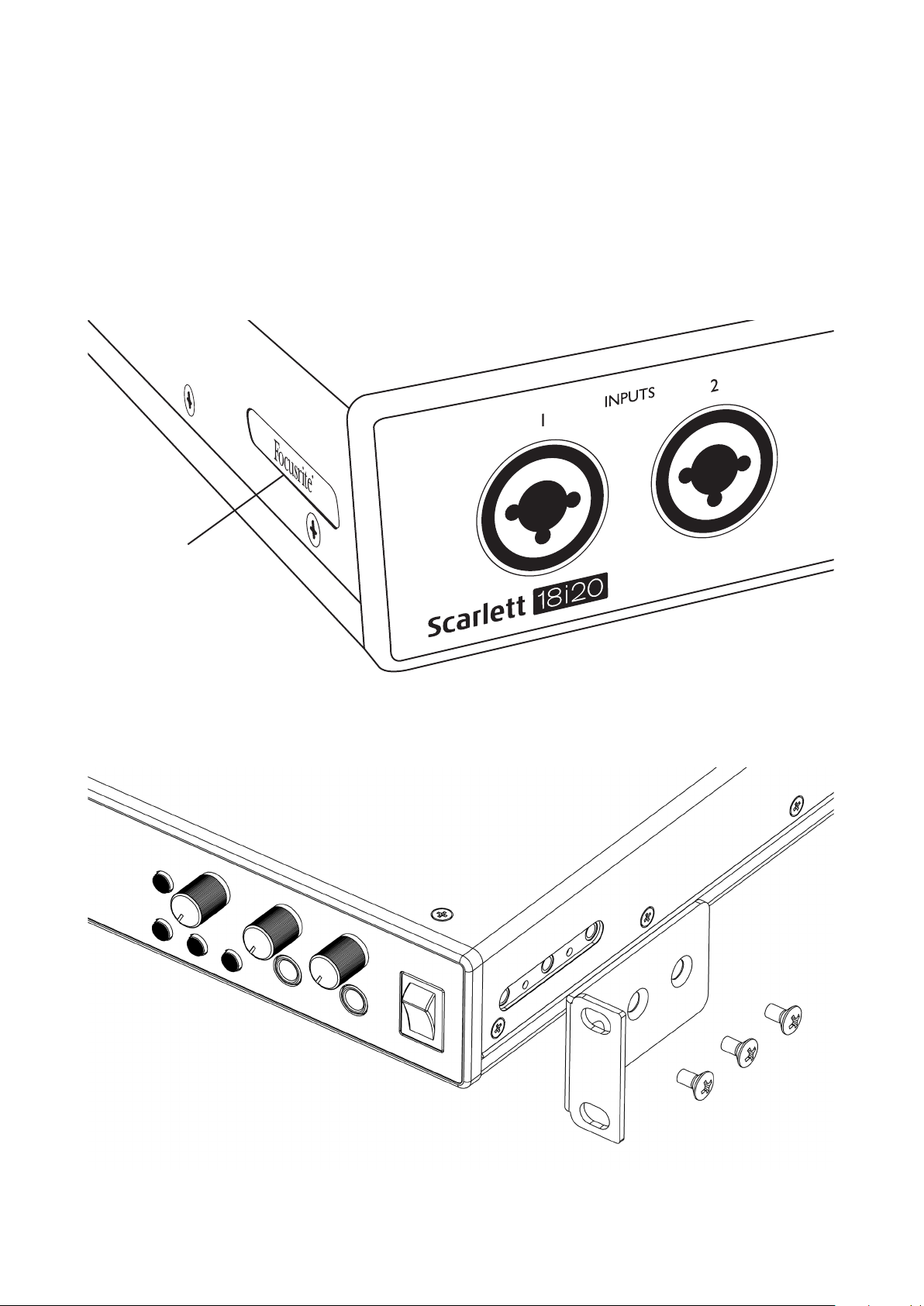
Rackmounting the Scarlett 18i20
The Scarlett 18i20 can be mounted in a standard 19” equipment rack. In order to do this, the rack
ears supplied with the unit need first to be fitted.
To fit the rack ears:
• Remove the rubber “Focusrite” inserts from the sides of the case. This will reveal three tapped
fixing holes:
Rubber Insert
• Fix the rack ears to the sides of the chassis using the three countersunk M4 screws supplied:
5
Page 6

GETTING STARTED
With the Third Generation, Scarlett interfaces introduce a new, faster way of getting up and running,
using the Scarlett Quick Start tool. All you need to do is connect your Scarlett 18i20 to your computer.
Once connected, you will see that the device is recognised by your PC or Mac and the Quick Start tool
will guide you through the process from there.
IMPORTANT: The Scarlett 18i20 has a single USB 2.0 Type C port (on the rear panel):
connect it to your computer using the USB cable provided. Note that Scarlett 18i20
is a USB 2.0 device, and thus the USB connection requires a USB 2.0+ compliant port
on your computer.
Your computer will initially treat your Scarlett as a Mass Storage Device (MSD), and during its first
connection, the Scarlett will be in “MSD Mode”
Quick Start Tool
We have tried to make registering your Scarlett 18i20 as simple as possible. The procedure will
probably be self explanatory, but we have described each step below, so you can see how they should
appear on either a PC or a Mac.
Mac users only:
On connecting your Scarlett 18i20 to your Mac, a Scarlett icon will appear on the desktop:
Double-click on the icon to open the Finder window shown on the following page.
6
Page 7
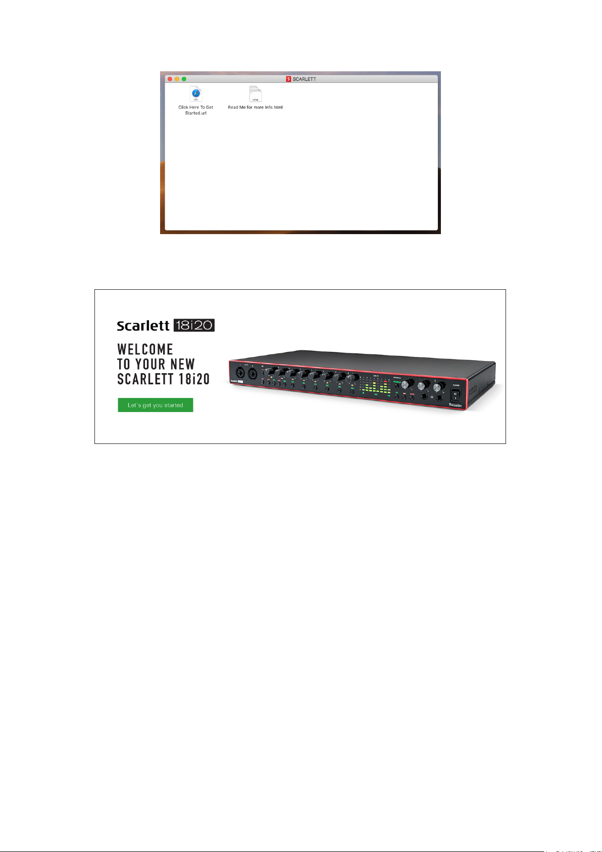
Double-click on the “Click Here to Get Started.url” icon. This will redirect you to the Focusrite
website, where we recommend that you register your device:
Click on “Let’s get you started”, and you’ll be presented with a form which will be partly prefilled
for you automatically. On submitting the form, options will be presented to either go straight to the
downloads area to get the software for your Scarlett, or to follow a step by step setup guide based
on your choices. Once you have installed the Focusrite Control software to set up and configure
your interface, the Scarlett will be switched out of MSD mode so that it no longer appears as a Mass
Storage Device when connected to your computer.
Your OS should automatically switch the computer’s default audio inputs and outputs to the
Scarlett 18i20. To verify this, go to System Preferences > Sound, and ensure that the
input and output are set to Scarlett 18i20. For more detailed setup options on a Mac, open:
Applications > Utilities > Audio MIDI Setup.
7
Page 8
Windows only:
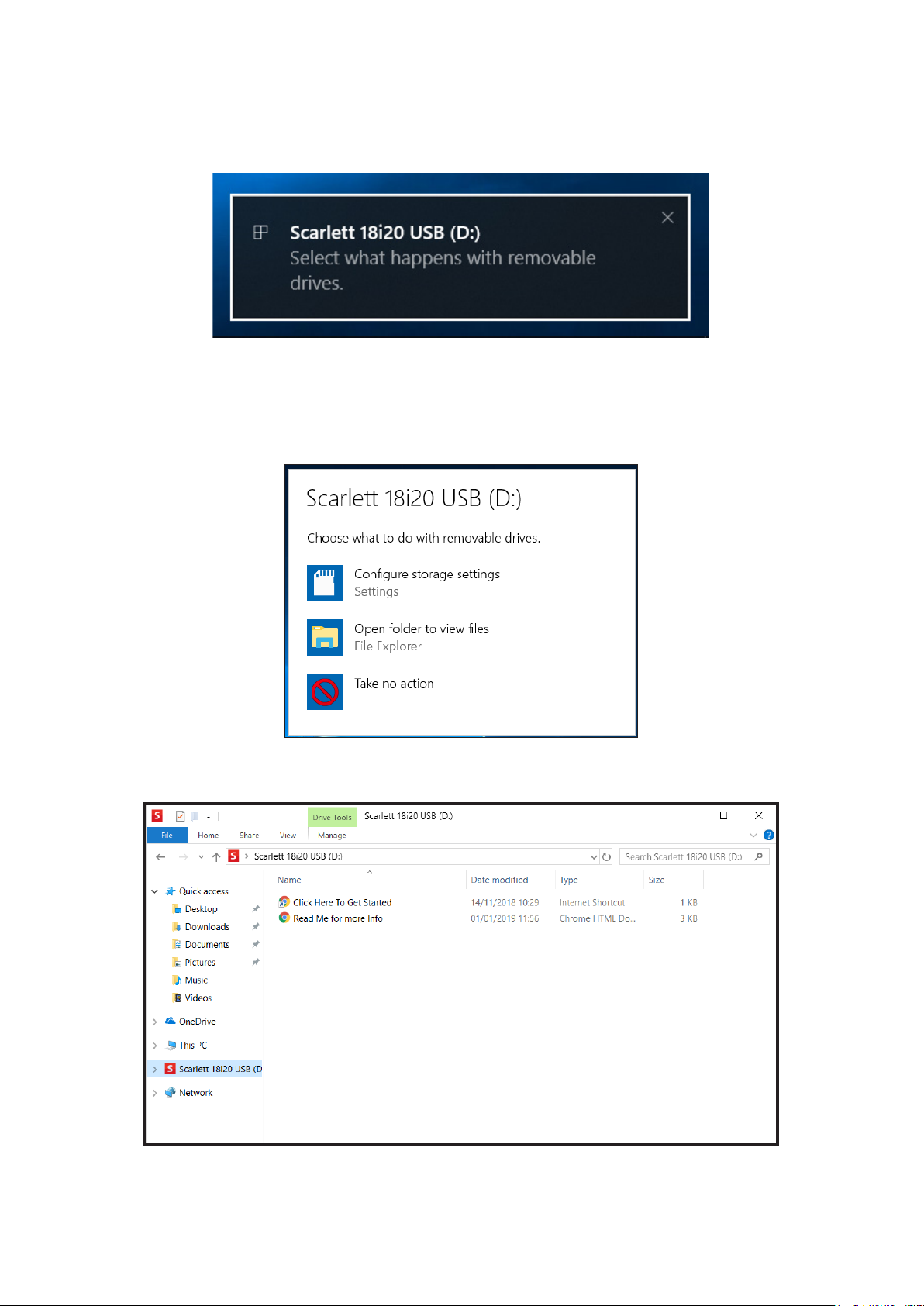
On connecting your Scarlett 18i20 to your PC, a Scarlett icon will appear on the desktop:
(Note that the drive letter may be something other than D:, depending on what other devices you
have connected to your PC).
Double-click on the pop-up message to open the dialogue box shown below:
Double-click on “Open folder to view files”: this will open an Explorer window:
8
Page 9

Double-click “Click Here to Get Started”. This will redirect you to the Focusrite website, where we
recommend that you register your device:
Click on “Let’s get you started”, and you’ll be presented with a form which will be partly prefilled
for you automatically. On submitting the form, options will be presented to either go straight to the
downloads area to get the software for your Scarlett, or to follow a step-by-step setup guide based
on your choices. Once you have installed the Focusrite Control software to set up and configure
your interface, the Scarlett will be switched out of MSD mode so that it no longer appears as a Mass
Storage Device when connected to your computer.
Your OS should automatically switch the computer’s default audio inputs and outputs to be the
Scarlett 18i20. To verify this, right click on the Sound icon on the taskbar and select Sound Settings,
and set the Scarlett as the Input and Output Device.
9
Page 10

All users:
Note that a second file - “More Info & FAQs” - is also available during the initial set-up process. This
file contains some additional information about the Focusrite Quick Start tool which you may find
helpful if you have any issues with the procedure.
Once registered, you will have immediate access to the following resources:
• Focusrite Control (Mac and Windows versions available) - see NOTE below
• Multi-language User Guides
Licence codes and links will be provided for the following bundled software within your account page.
• Pro Tools | First
• Ableton Live Lite
• Focusrite Red 2 & 3 Plug-in Suite
• Softube Time and Tone bundle
• XLN Audio Addictive Keys
• Plug-in Collective Offers
NOTE: Installing Focusrite Control will also automatically install the correct driver for your device.
Focusrite Control is available to download at any time, even without registering: see “Manual
Registration” below.
Manual Registration
If you decide to register your Scarlet 18i20 at a later date you can do so at :
https://customer.focusrite.com/user/register. You will need to enter the Serial Number manually:
this number can be found on the base of the interface itself, and can also on the barcode label on the
side of the box.
We recommend that you download and install our Focusrite Control application, as this will disable
MSD mode and unlock the full potential of the interface. Initially, when in MSD mode, the interface
will function at sample rates up to 48 kHz. Once Focusrite Control is installed on your computer, you
can work at sample rates up to 192 kHz. If you decide not to download and install Focusrite Control
immediately, it can be downloaded at any time from:
https://customer.focusrite.com/support/downloads.
In order to force your Scarlett 18i20 out of MSD mode without first registering it, hold down the
1-4 48V button while disconnecting and reconnecting the USB cable, and then continue to hold the
button down for a further five seconds. This will ensure that your Scarlett 18i20 has full functionality.
Please bear in mind that should you wish to register your Scarlett 18i20 after taking this action, you
will need to so manually, as explained above.
10
Page 11
HARDWARE FEATURES
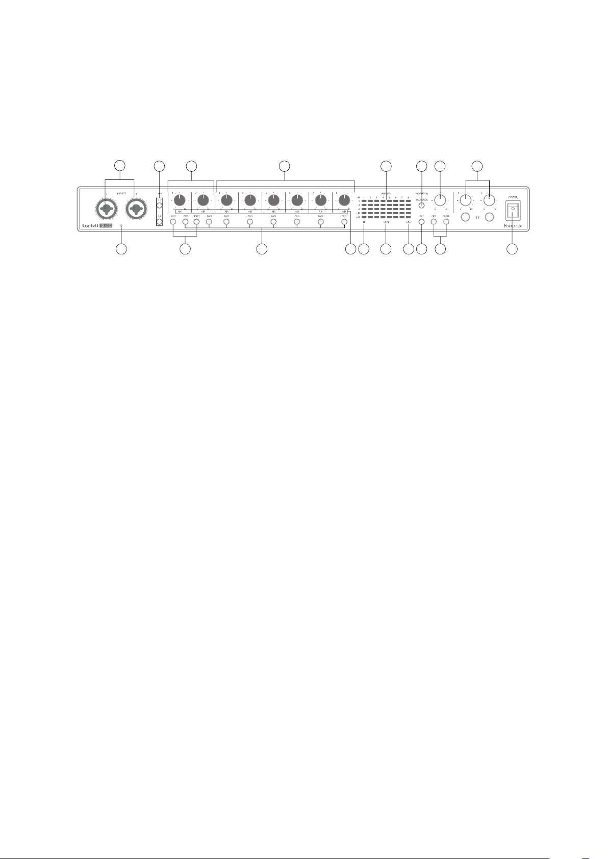
Front Panel
1
2
4 6 514
8 1215 1773
9 1610 11 1813
The front panel includes all the input gain and monitoring controls as well as two of the input
connectors for Mic, Line and Instrument signals.
1. Inputs 1 and 2 – Combo” type input sockets - connect microphones, instruments (e.g.,
guitar), or line level signals here. Combo sockets accept both XLR and ¼” (6.35 mm) jacks.
Microphones will normally be connected using XLR plugs: instruments and line level signals
should be connected via ¼” (6.35 mm) jack plugs of either TS or TRS type. The preamp gain is
appropriate for microphones when an XLR plug is inserted, and for higher level signals when
a jack plug is inserted. Do not connect anything other than a microphone - e.g., the output
of a sound module or FX unit - via an XLR plug, as the signal level will overload the preamp,
resulting in distortion; also, if phantom power is enabled, the equipment may be damaged.
2. 48V – two switches (1-4, 5-8) enabling 48 V phantom power at the XLR contacts of the Combo
connectors for mic inputs 1-4 and 5-8 respectively. (Note that inputs 3 to 8 are on the rear
panel.) The switches each have an associated red LED indicating that phantom power is
selected.
3. Gain 1 & 2 – adjust the input gain for the signals at Inputs 1 and 2 respectively.
4. INST – two switches changing the input configuration for the jack contacts at Inputs 1 and
2. When INST is selected, the gain range and input impedance are altered (relative to LINE),
and the input is made unbalanced. This optimises it for the direct connection of instruments
(usually via a 2-pole (TS) jack plug). When INST is off, the inputs are suitable for the connection
of line level signals. Line level signals may be connected either in balanced form via a 3-pole
(TRS) jack or unbalanced via a 2-pole (TS) jack. ‘INST’ illuminates red when Instrument mode
is selected. Note that INST may also be selected from Focusrite Control.
5. AIR – eight yellow LEDs indicating selection of AIR mode for each channel. AIR mode, selected
from Focusrite Control, modifies the frequency response of the input stage to model the
classic, transformer-based Focusrite ISA microphone preamps.
6. PAD – eight switches selecting the PAD function for each channel. PAD decreases the signal
level going to your DAW by 10 dB; use when the input source has a particularly high level.
‘PAD’ illuminates red when active. Note that PAD may also be selected from Focusrite Control.
7. Gain 3 to 8 – adjust the input gain for the signals at Inputs 3 to 8 respectively. (Note that the
connectors for these inputs are on the rear panel.)
11
Page 12

8. Input meters – eight 5-segment LED bargraph meters indicating the signal levels of the eight
analogue input signals. The meters show signal level after the input gain stage, and thus
their indication is affected by the gain controls. The LEDs illuminate at -42 (green, “signal
present”), -18 (green), -6 (green), -3 (yellow) and 0 dBFS (red). A level of 0 dBFS implies digital
clipping, and should always be avoided.
9.
10. Locked – a green LED which confirms clock synchronisation, either to the Scarlett 18i20’s
11. MIDI LED – green LED, illuminates when MIDI data is received at the MIDI IN port.
12. MONITOR – main monitor output level control: this will normally control the level at the main
13. DIM and MUTE – two switches controlling the 18i20’s monitor outputs; DIM reduces the
14. Talkback microphone
15. TALKBACK – press and hold this button to activate talkback. When active, ‘TALKBACK’
USB active LED – a green LED which illuminates when the unit is recognised by the
computer to which it is connected.
internal clock or to an external digital input.
monitor outputs on the rear panel, but can be configured in Focusrite Control to adjust the
level at any of the unit’s ten analogue outputs.
output levels by 18 dB, while MUTE turns the outputs off. By default, these switches affect
the MAIN monitor outputs 1 and 2, but may be configured in Focusrite Control to act on any
of the analogue outputs. The switches each have an associated LED (DIM: yellow, MUTE: red)
indicating that the function is selected. Note that DIM and MUTE may also be selected from
Focusrite Control.
illuminates green, and the talkback mic [14] may be routed to the 18i20’s various outputs.
By default, talkback routes to the two headphone outputs [17], but the routing may be
configured in Focusrite Control to feed any desired combination of outputs. Note this button
is ‘momentary’ – talkback is only active while it is pressed. Talkback may also be activated
from Focusrite Control.
16. ALT – when the ALT function is enabled in Focusrite Control, pressing this button diverts
the main monitor mix from MAIN LINE OUTPUTS 1 and 2 to ALT LINE OUTPUTS 3 and 4.
Connect a pair of secondary monitor speakers to the A LT outputs, and select ALT to switch
between your main monitors and the secondary pair. ‘ALT’ illuminates green when selected.
This function may also be selected from Focusrite Control. (Note that when ALT is enabled,
the line outputs not in use are muted: e.g., to use Line Outputs 3 and 4 for another purpose,
first unmute them in Focusrite Control.)
17. Headphone volume 1 and 2 – connect one or two pairs of stereo headphones at the two
¼” (6.25 mm) TRS jack sockets below the controls. The headphone outputs always carry
the signals that are currently routed to analogue outputs 7/8 and 9/10 (as stereo pairs) in
Focusrite Control.
18. POWER – AC power switch.
12
Page 13

Rear Panel
192028 2122
2427 2523 26
19. MIC/LINE INPUTS 3 to 8 – Combo type input sockets - connect further microphones or line
level signals via XLR or ¼” (6.35 mm) jacks as appropriate. Either ¼” TRS (balanced) or TS
(unbalanced) jack plugs can be used for line level signals.
20. LINE OUTPUTS 1 and 2 (MAIN) – two balanced analogue line outputs on ¼” (6.35 mm) jack
sockets; use TRS jacks for a balanced connection or TS jacks for unbalanced. We recommend
the use of balanced connections wherever possible, to minimise grounding and hum problems.
These will generally be used for driving the main L and R speakers of your monitoring system.
However, the signals at the outputs may be defined in Focusrite Control
21. LINE OUTPUTS 3 and 4 (ALT) – connect a secondary pair of monitor speakers here in order
to use the 18i20’s ALT function. The outputs are electrically identical to Line Outputs 1 and 2.
The signals at the outputs may be defined in Focusrite Control.
22. LINE OUTPUTS 5 to 10 – six further line outputs with identical electrical characteristics to
Line Outputs 1 to 4. The signals available at these outputs are defined in Focusrite Control,
and can typically be used for driving the additional speakers in a multichannel monitoring
system, or to drive outboard FX processors.
23. OPTICAL IN and OUT – four TOSLINK connectors for handling eight channels of digital audio
in ADAT format at either 44.1/48 kHz or 88.2/96 kHz sample rates. At 44.1/48 kHz sample
rate, only the right-hand port of each pair is used; at 88.2/96 kHz sample rate, both ports are
used, with the right-hand port carrying ADAT Channels 1-4 and the left-hand port carrying
ADAT Channels 5-8. (Note that the optical input and output are disabled when sample rates
of 176.4/192 kHz are in use.) The left-hand port of each pair (IN and OUT) may alternatively be
configured to receive and transmit a two-channel S/PDIF signal from/to an external source
equipped with optical S/PDIF I/O: this option is selected from Focusrite Control. Please refer
to the Channel Listing tables in the Appendix section for more details.
24. WORD CLOCK OUT – a BNC connector carrying the Scarlett 18i20’s word clock; this may be
used to synchronise other digital audio equipment forming part of the recording system. The
source of sample clock synchronisation used by the Scarlett 18i20 is selected from Focusrite
Control.
25.
USB 2.0 port – Type C connector; connect the Scarlett 18i20 to your computer with the
cable supplied.
26. MIDI IN and MIDI OUT – standard 5-pin DIN sockets for connection of external MIDI equipment.
The Scarlett 18i20 acts as a MIDI interface, allowing MIDI data to/from your computer to be
distributed to additional MIDI devices.
27. SPDIF IN and OUT – two phono (RCA) sockets carrying two-channel digital audio signals
into or out of the Scarlett 18i20, in S/PDIF format. Note that S/PDIF inputs and outputs are
unavailable at 176.4/192 kHz sample rates. Please refer to the Channel Listing tables in the
Appendix section for more details.
28. AC mains – standard IEC receptacle.
13
Page 14

Connecting your Scarlett 18i20
Power
The Scarlett 18i20 should be connected to AC mains with the supplied AC power cable. Plug the
IEC connector into the rear panel IEC receptacle. When using the Scarlett 18i20 with a computer
(i.e., not as a “stand-alone” mixer), we recommend that the unit is not turned on until the USB
connection has been made – see below.
USB
USB Port Types: The Scarlett 18i20 has a single Type C USB 2.0 port (on the rear panel). Once
the software installation is complete, simply connect the Scarlett 18i20 to your computer; if your
computer has a Type A USB port we recommend you use the Type A-to-Type C USB cable provided
with the unit. If your computer has a Type C USB port, please obtain a Type C-to-Type C cable from
a computer supplier.
USB Standards: Note that because the Scarlett 18i20 is a USB 2.0 device, the USB connection
requires a USB 2.0-compliant port on your computer. It will not operate correctly with USB 1.0/1.1
ports: however, typically a USB 3.0 port will support a USB 2.0 device.
When the USB cable has been connected, turn the Scarlett 18i20 on with the front panel power
switch.
14
Page 15

Audio Setup in your DAW
The Scarlett 18i20 is compatible with any Windows-based DAW that supports ASIO or WDM and any
Mac-based DAW that uses Core Audio. After following the Getting Started procedure described on
page 6, you can start using the Scarlett 18i20 with the DAW of your choice. To allow you to get
started if you do not already have a DAW application installed on your computer, both Pro Tools | First
and Ableton Live Lite are included; these will be available to you once you’ve registered your Scarlett
18i20. If you need help installing either DAW, please visit our Getting Started pages at
https://focusrite.com/get-started, where Getting Started videos are available.
Operating instructions for Pro Tools | First and Ableton Live Lite are beyond the scope of this
User Guide, but both applications include a full set of Help files. Instructions are also available at
www.avid.com and www.ableton.com respectively. You can find a video tutorial on getting started
with Ableton Live Lite at https://focusrite.com/get-started.
Please note - your DAW may not automatically select the Scarlett 18i20 as its default I/O device. In
this case, you must manually select the driver on your DAW’s Audio Setup* page (select Scarlett
18i20 for Mac or Focusrite USB ASIO for Windows). Please refer to your DAW’s documentation (or
Help files) if you are unsure where to select the ASIO/ Core Audio driver. The example below shows
the correct configuration in the Ableton Live Lite Preferences panel (Windows version shown).
* Typical name. Terminology may differ slightly between DAWs.
15
Page 16

Once the Scarlett 18i20 is set as the preferred Audio Device* in your DAW, all 18 inputs and 20 outputs
will appear in your DAW’s Audio I/O preferences (note however that Ableton Live Lite is limited to a
maximum of four simultaneous mono input channels and four simultaneous mono output channels).
Depending on your DAW, you may need to enable certain inputs or outputs before use. The two
examples below show two inputs and two outputs enabled in Ableton Live Lite’s Input Cong and
Output Cong pages.
* Typical name. Terminology may differ slightly between DAWs.
16
Page 17

Examples of Usage
The Scarlett 18i20 is an excellent choice for several different recording and monitoring applications.
Some typical configurations are shown below.
Recording a band
(Front Panel)
(Rear Panel)
Microphone
Guitar
Stereo
Headphone
Amplifier
Engineer’s Headphones
Stereo Keys
Musicians’ Individual
foldback mixes
This setup illustrates a typical configuration for recording a group of musicians with DAW software
on Mac or PC.
A selection of sources – microphones, guitar and a keyboard – are shown connected to the Scarlett
18i20’s inputs. Note that only Inputs 1 and 2 can be configured to accept instruments directly, so we
have chosen to plug the guitar into Input 2. Ensure that INST is selected for this input.
The connection to the PC or Mac running DAW software is via the USB cable supplied. This will carry
all the input and output signals between the DAW and the Scarlett 18i20. Once the audio setup is
correctly configured in the DAW, each input source will be automatically routed to its own DAW track
for recording.
17
Page 18

Low Latency Monitoring
Headphones
You will frequently hear the term “latency” used in connection with digital audio systems. In the
case of the simple DAW recording application described above, latency will be the time it takes for
your input signals to pass through your computer and audio software, and back out again via your
audio interface. While not an issue for most simple recording situations, under some circumstances,
latency can be a problem for a performer who wishes to record while monitoring their input signals.
This might be the case if you need to increase the size of your DAW’s recording buffer, which could
be necessary when you record overdubs on a particularly large project using many DAW tracks,
software instruments and FX plug-ins. Common symptoms of a buffer setting that is too low could
be glitching audio (clicks and pops), or a particularly high CPU load within your DAW (most DAWs
have a CPU monitoring function). Most DAWs will allow you adjust buffer size from their Audio
Preferences* control page.
The Scarlett 18i20, in conjunction with Focusrite Control, allows “zero latency monitoring”, which
overcomes this problem. You can route your input signals directly to the Scarlett 18i20’s headphone
outputs. This enables the musicians to hear themselves with ultra-low latency – i.e., effectively in
“real time” – along with the computer playback. The input signals to the computer are not affected
in any way by this setting. However, note that any effects being added to the live instruments by
software plug-ins will not be heard in the headphones in this case, although the FX will still be
present on the recording.
In the example, each of the band members is receiving his/her own monitor mix, because they each
have their “own” Scarlett 18i20 output. Focusrite Control lets you define up to eight separate mixes,
and these mixes may include previously recorded DAW tracks as well the current input signals.
Direct Monitoring
set up in
Focusrite Control
Guitar Bass
Headphones (Vocals) Headphones (Keyboards)
Headphone
Amplier
Keyboards
Headphones (Drums)
Headphone
Amplier
Kick
SnareOverheads Vocals
Headphones
(Guitar)
Headphone
Amplier
(Bass)
When using Direct Monitoring, ensure that your DAW software is not set to route any inputs (what you
are currently recording) to any outputs. If it is, the musicians will hear themselves “twice”, with one
signal audibly delayed as an echo.
18
Page 19

Connecting Scarlett 18i20 to loudspeakers
The 1/4” jack MAIN outputs on the rear panel (Line Outputs 1 and 2) will normally be used to drive
your primary monitoring speakers. Self-powered monitors incorporate internal amplifiers with a
volume control, and may be connected directly. Passive loudspeakers will require a separate stereo
amplifier; in this case, the rear panel outputs should be connected to the amplifier’s inputs.
Active Speakers
All the line output connectors are 3-pole (TRS) ¼” (6.35 mm) jack sockets, and are electronically
balanced. Typical consumer (hi-fi) amplifiers and small powered monitors will probably have
unbalanced inputs, either on phono (RCA) sockets, or via a 3.5 mm 3-pole jack plug intended for
direct connection to a computer. In either case, use a suitable connecting cable with jack plugs at
one end.
Professional active monitors and professional power amplifiers will generally have balanced inputs.
When mixing, you might want to use several pairs of additional speakers (mid-field. near-field, etc.)
to check how well your mix translates to other types of speaker. You can connect additional pairs of
19
Page 20

speakers to other pairs of Line Outputs (e.g., near-fields to Line Outputs 3 and 4, mid-fields to Line
Outputs 5 and 6) and switch between them in Focusrite Control. Scarlett 18i20’s ALT function (see
below) has been included to make using a second pair of monitors very simple.
IMPORTANT:
LINE OUTPUTS 1 to 4 incorporate “anti-thump” circuitry that protects your speakers if the
Scarlett 18i20 is turned on while the speakers (and amplifier if used) are connected and
active.
LINE OUTPUTS 5 to 10 do not have this circuitry. If you’re using additional speakers
connected to these outputs, we recommend that you first power your Scarlett 18i20 on, then
turn on the speakers or power amplifier.
But get into the habit of following this general rule in any case - it is always good audio
practice to turn on a speaker system of any kind after turning on the equipment feeding it.
NOTE: You run the risk of creating an audio feedback loop if loudspeakers are active at the same time
as a microphone! We recommend that you always turn off (or turn down) monitoring loudspeakers
while recording, and use headphones when overdubbing.
Speaker Switching
The 18i20’s Speaker Switching function makes adding a second pair of monitors very easy: simply
connect the second pair to the ALT outputs – LINE OUTPUTS 3 and 4. After enabling Speaker
Switching in Focusrite Control, you can then switch between your main monitors and the secondary
pair either by pressing the front panel ALT button, or by clicking on the corresponding on-screen
button in Focusrite Control. When ALT is active, the main mix output will be fed to the ALT outputs
instead of the MAIN, and the green ALT LED will light to confirm this.
In the example below, we have shown passive speakers with a separate power amplifier as the main
monitors and active speakers as the secondary pair, but of course, any type of monitors you prefer
may be used in either case.
ALTMAIN
20
Secondary
Monitors
(Active)
Main
Monitors
(Passive)
Page 21

Working with surround sound
Because the Scarlett 18i20 is equipped with ten line outputs, it is ideally suited for use when working
in multichannel sound formats – LCRS, 5.1 surround or 7.1 surround, for example.
In order to route each channel to the correct output you will need to route the DAW outputs to the
Line Outputs in Focusrite Control (e.g. DAW Output 1 > Line Output 1, DAW Output 2 > Line Output
2, etc.).
Windows users:
In Windows, surround sound can only be used in software supporting multichannel ASIO. In most
cases this will be your DAW, and in general, DAWs capable of mixing in surround allow you to set the
speaker mapping up in the DAW’s Audio Output Preferences or I/O Settings page.
Please see the User Manual (or Help files) for your DAW for guidance on setting up the outputs for
surround mixing with the speaker configuration you wish to use.
Mac users:
On Macs, surround sound configuration can be done from all applications that support multichannel
audio (DAWs & regular macOS Applications). To do this, go to: Applications > Utilities >
Audio MIDI Setup > Scarlett 18i20 > Congure Speakers > Conguration > Select the
desired conguration.
21
Page 22

The example below shows how you would connect the six loudspeakers in a 5.1 surround monitoring
g
arrangement.
Left (L)
Right (R)
Centre (C)
(Sub Bass) LFE
Rear Left (RL) Rear Ri
ht (RR)
22
Page 23

Using the ADAT connection
Up to 16 Mic/Line Sources
In addition to the eight analogue inputs, the Scarlett 18i20 has two OPTICAL IN ADAT input ports
which can provide an additional eight audio inputs at sample rates up to 96 kHz. Note that the optical
input is disabled when sample rates of 176.4/192 kHz are in use.
Using a separate 8-channel microphone preamplifier equipped with an ADAT output – such as the
Focusrite Scarlett OctoPre – provides a simple and excellent method of expanding the Scarlett
18i20’s input capability.
Inputs 1 & 2 on front panel
Scarlett OctoPre
8ch Mic Amp
Additional TOSlink connection required at 96 kHz
Optical ADAT connection (TOSLINK)
Computer
running DAW
and
Focusrite
Control
Wordclock link
Inputs 1 & 2 on front panel
At 44.1/48 kHz, the Scarlett OctoPre’s ADAT OUT 1-8 port is connected to the Scarlett 18i20 OPTICAL
IN port marked 48 – 1-8 with a single TOSLINK optical cable. To synchronise the two devices over
ADAT, set the clock source of the Scarlett OctoPre to Internal and that of the Scarlett 18i20 (via
Focusrite Control) to ADAT. Alternatively, stable clock synchronisation may be achieved by connecting
the Scarlett 18i20’s WORD CLOCK OUT to the Scarlett OctoPre’s WORD CLOCK IN and setting the
Scarlett OctoPre to use Word Clock as its clock source. In this case, set the Scarlett 18i20’s clock
source in Focusrite Control to Internal.
TIP: When interconnecting two digital devices by any method, always ensure that both are set
to the same sample rate.
The additional inputs realised by use of the ADAT port may be routed using Focusrite Control in
exactly the same manner as the other inputs. The additional inputs can form part of any musician’s
headphone mix, as required.
When working at 88.2/96 kHz, add a second TOSlink optical cable between the Scarlett OctoPre’s
ADAT OUT 5-8 port and the 18i20’s OPTICAL IN 5-8 – 96 port. At the higher sample rate, this second
link will carry Channels 5-8, while the other link (described above) will carry Channels 1 to 4.
23
Page 24

If a suitable multi-channel digital-to-analogue converter is available, the 18i20’s OPTICAL OUT ADAT
ports may be used in the opposite manner; for example, additional outputs from the DAW may be
converted into the analogue domain to allow the use of an external hardware mixing console to mix
down a large number of DAW tracks. At 44.1/48 kHz sample rate, the right-hand OPTICAL OUT port
carries Channels 1 to 8, while at 88.2/96 kHz, the right-hand port carries Channels 1 to 4 and the
left-hand port Channels 5 to 8.
Using the Scarlett 18i20 as a stand-alone mixer
The Scarlett 18i20 has the ability to store a mix configuration defined in Focusrite Control within the
hardware. This feature lets you configure it – for example, as an on-stage keyboard mixer – using
your computer, and then upload the configuration to the device itself. Then you can use the Scarlett
18i20 as a simple local mixer as part of your keyboard rig to control the overall mix of multiple
keyboards.
To FOH Mixer
In the example illustrated, three stereo keyboards are connected to the rear panel inputs of the
Scarlett 18i20; Outputs 3 and 4 go to the main PA system. The performer can adjust the gain
for the individual keyboards from the front panel; he/she can also adjust the overall level of the
keyboard mix.
24
Page 25

FOCUSRITE CONTROL
Focusrite Control software allows flexible mixing and routing of all audio signals to the physical
audio outputs, as well as control of output monitor levels. Sample rate selection and digital sync
options are also available from Focusrite Control.
NOTE: Focusrite Control is a generic product, and may be used with several
other Focusrite hardware interfaces. When you connect an interface to
your computer and launch Focusrite Control, the model of interface is
automatically detected, and the software configured to suit the number of
inputs and outputs, and other facilities, available on the hardware.
IMPORTANT: A separate Focusrite Control User Guide can be downloaded
from the downloads area of the Focusrite website. This describes the use of
Focusrite Control in full detail, together with examples of application.
To open Focusrite Control:
Installing Focusrite Control on your computer will place an FC icon on the dock or desktop.
Click the icon to launch Focusrite Control.
Assuming that your Scarlett interface is connected to your computer with the USB cable, the Focusrite
Control GUI (Graphical User Interface) will appear as shown below (Mac version illustrated).
Please refer to the Focusrite Control User Guide for further details.
25
Page 26

Channel Listing tables
The 18i20’s inputs and outputs will appear in Focusrite Control with slightly different channel
numbers depending on the sample rate being used. The channel numbers will also vary when the
optical ADAT ports are in use, depending on which Digital I/O Mode is selected (see Digital I/O Modes
below).
Digital I/O Modes
The Scarlett 18i20 supports three Digital I/O modes: these are selected from the Device Settings
pane of Focusrite Control. The modes determine how the audio inputs and outputs are mapped to
the optical (ADAT) ports and the S/PDIF input and output coaxial (RCA) sockets.
Mode 1: Coaxial (RCA) S/PDIF
This is the factory default mode, and your Scarlett 18i20 will adopt these assignments “out-of-thebox”. Use this mode if you need a coaxial S/PDIF audio input, or if you wish to use a coaxial S/PDIF
signal as a clock source.
Digital port
S/PDIF IN S/PDIF S/PDIF S/PDIF
Inputs
Outputs
Mode 2: Optical S/PDIF
Select this mode when you are working at 44.1/48 or 88.2/96 kHz sample rate and you need to send
or receive an S/PDIF signal via an optical port. Also use this mode if you want to use a clock source
sent as an optical S/PDIF signal.
Digital port
Inputs
Outputs
OPTICAL IN 1 ADAT 1-8 ADAT 1-4 x
OPTICAL IN 2 x x x
S/PDIF OUT S/PDIF S/PDIF S/PDIF
OPTICAL OUT 1 ADAT 1-8 ADAT 1-4 x
OPTICAL OUT 2 ADAT 1-8 ADAT 1-4 x
S/PDIF IN x x x
OPTICAL IN 1 ADAT 1-8 ADAT 1-4 x
OPTICAL IN 2 S/PDIF S/PDIF x
S/PDIF OUT S/PDIF S/PDIF S/PDIF
OPTICAL OUT 1 ADAT 1-8 ADAT 1-4 x
OPTICAL OUT 2 S/PDIF S/PDIF x
44.1/48 88.2/96 176.4/192
44.1/48 88.2/96 176.4/192
Sample rate (kHz)
Sample rate (kHz)
26
Page 27

Mode 3: Dual ADAT
Select this mode when you need more than four ADAT input and/or output channels when working
at 88.2/96 kHz sample rate.
Inputs
Outputs
Digital port
Sample rate (kHz)
44.1/48 88.2/96 176.4/192
S/PDIF IN x x x
OPTICAL IN 1 ADAT 1-8 ADAT 1-4 x
OPTICAL IN 2 x ADAT 5-8 x
S/PDIF OUT S/PDIF S/PDIF S/PDIF
OPTICAL OUT 1 ADAT 1-8 ADAT 1-4 x
OPTICAL OUT 2 ADAT 1-8 ADAT 5-8 x
27
Page 28

The tables below list the how the 18i20’s inputs and outputs appear in Focusrite Control for each of
the three Optical I/O modes, at each of the three sample rate pairs. Note that the first digit in the
entries relating to the ADAT channels refers to the port in use: so “ADAT 1.1” to “ADAT 1.4” are ADAT
Chs 1 to 4 at the right-hand port of each pair, while “ADAT 2.1” to “ADAT 2.4” are ADAT Chs 5 to 8 at
the left-hand port of each pair.
At 44.1 kHz and 48 kHz sample rates:
DIGITAL I/O MODE
INPUTS
Input 1 Input 1 Input 1 Input 1
Input 2 Input 2 Input 2 Input 2
Input 3 Input 3 Input 3 Input 3
Input 4 Input 4 Input 4 Input 4
Input 5 Input 5 Input 5 Input 5
Input 6 Input 6 Input 6 Input 6
Input 7 Input 7 Input 7 Input 7
Input 8 Input 8 Input 8 Input 8
Loopback 1 Loopback 1 Loopback 1 Loopback 1
Loopback 2 Loopback 2 Loopback 2 Loopback 2
Digital In 1
Digital In 2
Digital In 3 ADAT 1.1 ADAT 1.1 ADAT 1.1
Digital In 4 ADAT 1.2 ADAT 1.2 ADAT 1.2
Digital In 5 ADAT 1.3 ADAT 1.3 ADAT 1.3
Digital In 6 ADAT 1.4 ADAT 1.4 ADAT 1.4
Digital In 7 ADAT 1.5 ADAT 1.5 ADAT 1.5
Digital In 8 ADAT 1.6 ADAT 1.6 ADAT 1.6
Digital In 9 ADAT 1.7 ADAT 1.7 ADAT 1.7
Digital In 10 ADAT 1.8 ADAT 1.8 ADAT 1.8
COAXIAL
S/PDIF
S/PDIF 1
(via co-ax
socket)
S/PDIF 2
(via co-ax
socket)
OPTICAL
S/PDIF
S/PDIF 1
(via optical
port)
S/PDIF 2
(via optical
port)
DUAL
ADAT
x
x
DIGITAL I/O MODE
OUTPUTS
Output 1 Output 1 Output 1 Output 1
Output 2 Output 2 Output 2 Output 2
Output 3 Output 3 Output 3 Output 3
Output 4 Output 4 Output 4 Output 4
Output 5 Output 5 Output 5 Output 5
Output 6 Output 6 Output 6 Output 6
Output 7 Output 7 Output 7 Output 7
Output 8 Output 8 Output 8 Output 8
Output 9 Output 9 Output 9 Output 9
Output 10 Output 10 Output 10 Output 10
Output 11
Output 12
Output 13 ADAT 1.1 ADAT 1.1 ADAT 1.1
Output 14 ADAT 1.2 ADAT 1.2 ADAT 1.2
Output 15 ADAT 1.3 ADAT 1.3 ADAT 1.3
Output 16 ADAT 1.4 ADAT 1.4 ADAT 1.4
Output 17 ADAT 1.5 ADAT 1.5 ADAT 1.5
Output 18 ADAT 1.6 ADAT 1.6 ADAT 1.6
Output 19 ADAT 1.7 ADAT 1.7 ADAT 1.7
Output 20 ADAT 1.8 ADAT 1.8 ADAT 1.8
COAXIAL
S/PDIF
S/PDIF 1
(via co-ax
socket)
S/PDIF 2
(via co-ax
socket)
OPTICAL
S/PDIF
S/PDIF 1 (via
co-ax socket and
optical port)
S/PDIF 2 (via
coaxial socket
and optical port)
DUAL
ADAT
S/PDIF 1
(via co-ax
socket)
S/PDIF 2
(via co-ax
socket)
28
Page 29

At 88.2 kHz and 96 kHz sample rates:
DIGITAL I/O MODE
INPUTS
Input 1 Input 1 Input 1 Input 1
Input 2 Input 2 Input 2 Input 2
Input 3 Input 3 Input 3 Input 3
Input 4 Input 4 Input 4 Input 4
Input 5 Input 5 Input 5 Input 5
Input 6 Input 6 Input 6 Input 6
Input 7 Input 7 Input 7 Input 7
Input 8 Input 8 Input 8 Input 8
Loopback 1 Loopback 1 Loopback 1 Loopback 1
Loopback 2 Loopback 2 Loopback 2 Loopback 2
Digital In 1
Digital In 2
Digital In 3 ADAT 1. 1 ADAT 1. 1 ADAT 1.3
Digital In 4 ADAT 1. 2 ADAT 1. 2 ADAT 1.4
Digital In 5 ADAT 1. 3 ADAT 1. 3 ADAT 2.1
Digital In 6 ADAT 1. 4 ADAT 1. 4 ADAT 2.2
Digital In 7 x x ADAT 2.3
Digital In 8 x x ADAT 2.4
COAXIAL S/
PDIF
S/PDIF 1
(via co-ax
socket)
S/PDIF 2
(via co-ax
socket)
OPTICAL S/
PDIF
S/PDIF 1
(via optical
port)
S/PDIF 2
(via optical
port)
DUAL ADAT
ADAT 1.1
ADAT 1.2
DIGITAL I/O MODE
OUTPUTS
Output 1 Output 1 Output 1 Output 1 Output 1
Output 2 Output 2 Output 2 Output 2 Output 2
Output 3 Output 3 Output 3 Output 3 Output 3
Output 4 Output 4 Output 4 Output 4 Output 4
Output 5 Output 5 Output 5 Output 5 Output 5
Output 6 Output 6 Output 6 Output 6 Output 6
Output 7 Output 7 Output 7 Output 7 Output 7
Output 8 Output 8 Output 8 Output 8 Output 8
Output 9 Output 9 Output 9 Output 9 Output 9
Output 10 Output 10 Output 10 Output 10 Output 10
Output 11
Output 12
Output 13 ADAT 1. 1 ADAT 1. 1 ADAT 1. 1 ADAT 1. 3
Output 14 ADAT 1. 2 ADAT 1. 2 ADAT 1. 2 ADAT 1. 4
Output 15 ADAT 1. 3 ADAT 1. 3 ADAT 1. 3 ADAT 2.1
Output 16 ADAT 1. 4 ADAT 1. 4 ADAT 1. 4 ADAT 2.2
Output 17 x x ADAT 2.1 ADAT 2.3
Output 18 x x ADAT 2.2 ADAT 2.4
Output 19 x x x x
Output 20 x x x x
COAXIAL
S/PDIF
S/PDIF 1
(via co-ax
socket)
S/PDIF 2
(via co-ax
socket)
OPTICAL
S/PDIF
S/PDIF 1
(via co-ax
socket
and
optical
port)
S/PDIF
2 (via
coaxial
socket
and
optical
port)
DUAL
ADAT
S/PDIF 1
(via co-ax
socket)
S/PDIF 2
(via co-ax
socket)
DUAL
ADAT
OUTPUT
PRESET*
ADAT 1. 1
ADAT 1. 2
29
*In order to obtain eight ADAT output channels, please select
Focusrite Control’s DUAL ADAT OUTPUT preset.
Page 30

At 176.4 kHz and 192 kHz sample rates:
DIGITAL I/O MODE
INPUTS
Input 1 Input 1 Input 1 Input 1
Input 2 Input 2 Input 2 Input 2
Input 3 Input 3 Input 3 Input 3
Input 4 Input 4 Input 4 Input 4
Input 5 Input 5 Input 5 Input 5
Input 6 Input 6 Input 6 Input 6
Input 7 Input 7 Input 7 Input 7
Input 8 Input 8 Input 8 Input 8
Digital In 1
Digital In 2
COAXIAL
S/PDIF
S/PDIF 1
(via co-ax
socket)
S/PDIF 2
(via co-ax
socket)
OPTICAL
S/PDIF
x x
x x
DUAL
ADAT
DIGITAL I/O MODE
OUTPUTS
Output 1 Output 1 Output 1 Output 1
Output 2 Output 2 Output 2 Output 2
Output 3 Output 3 Output 3 Output 3
Output 4 Output 4 Output 4 Output 4
Output 5 Output 5 Output 5 Output 5
Output 6 Output 6 Output 6 Output 6
Output 7 Output 7 Output 7 Output 7
Output 8 Output 8 Output 8 Output 8
Output 9 Output 9 Output 9 Output 9
Output 10 Output 10 Output 10 Output 10
Output 11 x x x
Output 12 x x x
Output 13 x x x
Output 14 x x x
Output 15 x x x
Output 16 x x x
Output 17 x x x
Output 18 x x x
Output 19 x x x
Output 20 x x x
COAXIAL
S/PDIF
OPTICAL
S/PDIF
DUAL ADAT
30
Page 31

SPECIFICATIONS
Performance Specifications
NOTE: All performance figures measured in accordance with the provisions of AES17, as applicable.
Configuration
Inputs 18: analogue (8), ADAT (8), S/PDIF (2)
Outputs 20: analogue (10), ADAT (8), S/PDIF (2)
Mixer
Supported sample rates 44.1 kHz, 48 kHz, 88.2 kHz, 96 kHz, 176.4 kHz, 192 kHz
Microphone Inputs 1 to 8
Dynamic Range 111 dB (A-weighted)
Frequency Response 20 Hz to 20 kHz ±0.1 dB
THD+N
Noise EIN –128 dB (A-weighted)
Maximum Input Level
Gain Range 56 dB
Input Impedance 3 kohms
Line Inputs 1 to 8
Dynamic Range 110.5 dB (A-weighted)
Fully assignable 18-in/10-out software mixer (Focusrite
Control)
< 0.0012% (minimum gain, -1 dBFS input with 22 Hz/22 kHz
bandpass filter)
+9 dBu (no PAD); +16 dBu (PAD selected); measured at
minimum gain
Frequency Response 20 Hz to 20 kHz ±0.1 dB
THD+N
Maximum Input Level
Gain Range 56 dB
Input Impedance 60 kohms
Instrument Inputs 1 and 2
Dynamic Range 110 dB (A-weighted)
Frequency Response 20 Hz to 20 kHz ±0.1 dB
31
< 0.002% (minimum gain, -1 dBFS input with 22 Hz/22 kHz
bandpass filter)
+22 dBu (no PAD); +29.5 dBu (PAD selected); measured at
minimum gain
Page 32

THD+N
< 0.03% (minimum gain, -1 dBFS input with 22 Hz/22 kHz
bandpass filter)
Maximum Input Level
Gain Range 56 dB
Input Impedance 1.5 Mohms
Line Outputs 1 to 10
Dynamic Range 108.5 dB (A-weighted)
Maximum Output Level (0 dBFS) +15.5 dBu (balanced)
THD+N
Output Impedance 430 ohms
Headphone Outputs
Dynamic Range 104 dB (A-weighted)
Maximum Output Level +7 dBu
THD+N
+12.5 dBu (no PAD); +14 dBu (PAD selected); measured at
minimum gain
< 0.002% (minimum gain, -1 dBFS input with 22 Hz/22 kHz
bandpass filter)
< 0.002% (measured at +6 dBu with 22 Hz/22 kHz bandpass
filter)
Output Impedance < 1 ohm
32
Page 33

Physical and Electrical Characteristics
Analogue Inputs 1 & 2
Connectors XLR Combo type: Mic/Line/Inst, on front panel
Mic/Line switching Automatic
Line/Instrument switching 2 x front panel switches or via Focusrite Control
Pad 10 dB attenuation, selected per channel from Focusrite Control
Phantom power Shared +48 V phantom power switch for inputs 1 to 4
AIR function Selected per channel from Focusrite Control
Analogue Inputs 3 to 8
Connectors XLR Combo: Mic/Line, on rear panel
Mic/Line switching Automatic
Pad 10 dB attenuation, selected per channel from Focusrite Control
Phantom power Shared +48 V phantom power switches for inputs 1 to 4 and 5 to 8
AIR function Selected per channel from Focusrite Control
Analogue Outputs
Main outputs 10 x balanced ¼” TRS jacks on rear panel
Stereo headphone outputs 2 x ¼” TRS jack on front panel
Main monitor output level control
On front panel
Headphones level controls
Other I/O
Optical I/O
S/PDIF I/O 2 x phono (RCA) or via Optical I/O (selected via Focusrite Control)
Word clock output BNC connector
USB 1 x USB 2.0 Type C connector
4 x TOSLINK optical connectors; 8 channels @ 44.1/48 kHz or 4
@ 88.2/96 kHz
MIDI I/O 2 x 5-pin DIN sockets
33
Page 34

Front Panel indicators
USB/Power Green LED
Phantom power 2 x red LEDs (Chs 1-4, 5-8)
Instrument mode 2 x red LEDs (Chs 1 & 2)
AIR mode 8 x yellow LEDs
Pad active 8 x green LEDs
MIDI data received Green LED
Lock indicator Green LED
Talkback active Green LED
ALT speakers selected Green LED
Monitors DIM and MUTE Yellow LED (DIM); red LED (MUTE)
Weight and Dimensions
W x D x H
Weight
482.6 mm x 46.6 mm (1U) x 259.8 mm
19 in x 1.83 in (1U) x 10.23 in
3.195 kg
7.16 lb
34
Page 35

TROUBLESHOOTING
For all troubleshooting queries, please visit the Focusrite Help Centre at
http://support.focusrite.com/ where you will find articles covering numerous
troubleshooting examples.
COPYRIGHT AND LEGAL NOTICES
Your Scarlett 18i20 has a two-year warranty, valid anywhere in the world, against manufacturing
defects. Full Terms and Conditions of the Warranty can be found at https://focusrite.com/warranty.
Focusrite is a registered trade mark and Scarlett 18i20 is a trade mark of Focusrite Audio Engineering
Limited.
All other trade marks and trade names are the property of their respective owners.
2019 © Focusrite Audio Engineering Limited. All rights reserved.
35
Page 36

36
 Loading...