

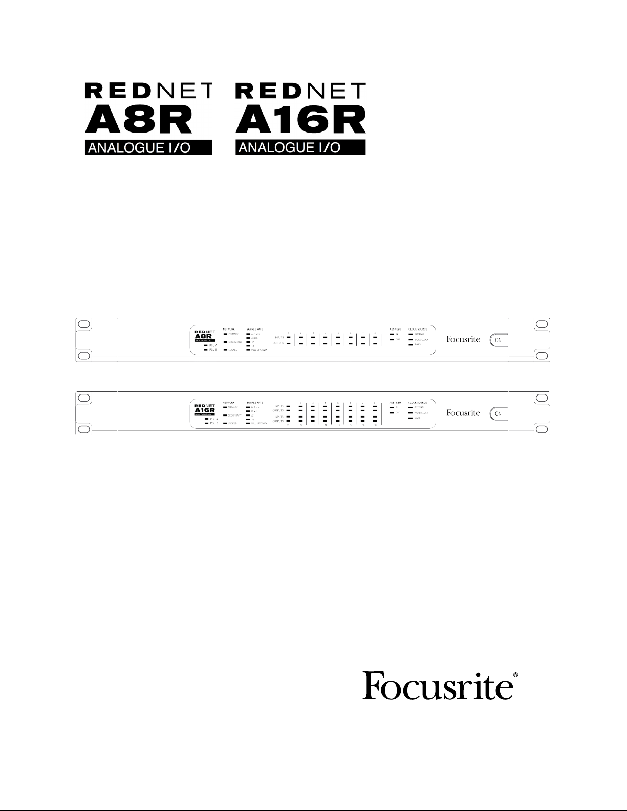
Focusrite Rednet A8R, Rednet A16R User Manual
User Guide
www.focusrite.com
FFFA001382-03

2
CONTENTS
About this User Guide .........................................................3
Box Contents ................................................................3
INTRODUCTION ................................................................4
INSTALLATION GUIDE ...........................................................5
RedNet A8R/A16R Connections and Features .....................................5
Front Panels............................................................5
Rear Panels ............................................................7
Power Connection ............................................................9
IEC Power Cord Retaining Clip.............................................9
Physical Characteristics ......................................................10
Power Requirements.........................................................10
REDNET A8R/A16R OPERATION .................................................11
First Use and Firmware Updates...............................................11
Digital Clocking .............................................................11
Pull Up and Pull Down Operation...............................................11
Sample Rate Converters......................................................11
OTHER REDNET SYSTEM COMPONENTS ..........................................12
USING REDNET CONTROL.......................................................12
Signal Metering .............................................................12
ID (Identification) ............................................................13
Tools Menu .................................................................13
APPENDIX.................................................................... 14
Connector Pinouts...........................................................14
Ethernet Connector.....................................................14
DB-25 (AES59) Connector................................................14
XLR Connectors ........................................................14
PERFORMANCE AND SPECIFICATIONS............................................ 15
Focusrite RedNet Warranty and Service .........................................18
Registering Your Product .....................................................18
Customer Support and Unit Servicing ...........................................18
Troubleshooting ............................................................18

3
About this User Guide
This user guide applies to both the RedNet A8R and RedNet A16R analogue interfaces. It provides
information about installing and using each unit and how either can be connected into your system.
All information relating to the RedNet A8R is also applicable to the RedNet A16R. Where channel
quantities or information differs between the two units, the detail for the A16R unit will be appended
in square brackets, eg., “8 [16] channels”.
A RedNet System User Guide is also available from the RedNet product pages of the Focusrite
website. The guide provides a detailed explanation of the RedNet system concept, that will help you
achieve a thorough understanding of its capabilities. We recommend that all users, including those
already experienced in digital audio networking, take the time to read through the System User
Guide so that they are fully aware of all the possibilities that RedNet and its software have to offer.
Should either user guide not provide the information you need, be sure to consult:
www.focusrite.com/rednet, which contains a comprehensive collection of common technical support
queries.
Box Contents
• RedNet A8R [A16R] unit
• 2 x IEC AC mains cables
• 2 x IEC mains cable retaining clips (See instructions on page 9)
• Safety information cut sheet
• RedNet Getting Started Guide
• Product registration card, which provides links to:
RedNet Control
RedNet PCIe drivers (included with RedNet Control download)
Audinate Dante Controller (installed with RedNet Control)
Dante Virtual Soundcard (DVS) Token and download instructions
Dante™ and Audinate™ are registered trademarks of Audinate Pty Ltd.
4
INTRODUCTION
Thank you for purchasing the Focusrite RedNet A8R/A16R.
RedNet A8R/A16R is a 1U 19in rack-mount interface featuring 8 [16] channels of A-D/D-A plus one
AES/EBU channel-pair for the Dante audio-over-IP network. Specifically tailored for the road, livesound and broadcast environments, each unit features network and power redundancy, rugged
construction with latching connectors, remote control and remote monitoring.
Dual Ethernet connectors (primary and secondary) on the rear-panel allow maximum network
reliability with seamless switchover to a standby network in the unlikely event of a network failure.
These ports may also be used to daisy-chain additional units when operating in Switched mode.
Redundant power supplies (PSU A and B) with separate input sockets on the rear panel allow one
supply to be connected to an uninterruptible source. Each PSU’s status can be monitored remotely
over the network or from the front panel.
RedNet A8R/A16R has a Sample Rate Converter (SRC) on the AES/EBU input pair allowing instant
operation with any AES/EBU source irrespective of the sample rate or clocking of the Dante network.
Audio interface is provided by two [four] standard 8-way (AES59) DB-25 connections. In addition,
channels 9-10 [17-18*] act as the AES/EBU channels.
[*When operating at quad sample rates, channels 17-18 are no longer available, meaning that the user can
select either: 1-16 analogue -or- 1-14 analogue and 15-16 AES/EBU.]
Word Clock I/O on BNC connectors allows synchronisation of the Dante network to house clock, or
syncing external equipment to the Dante network. DARS reference can also be accepted via the XLR
input connector.
The RedNet A8R/A16R front panel contains a set of LEDs to confirm PSU status, network status,
sample rate, clock sources and signal presence on AES/EBU and signal metering on Analogue I/O.
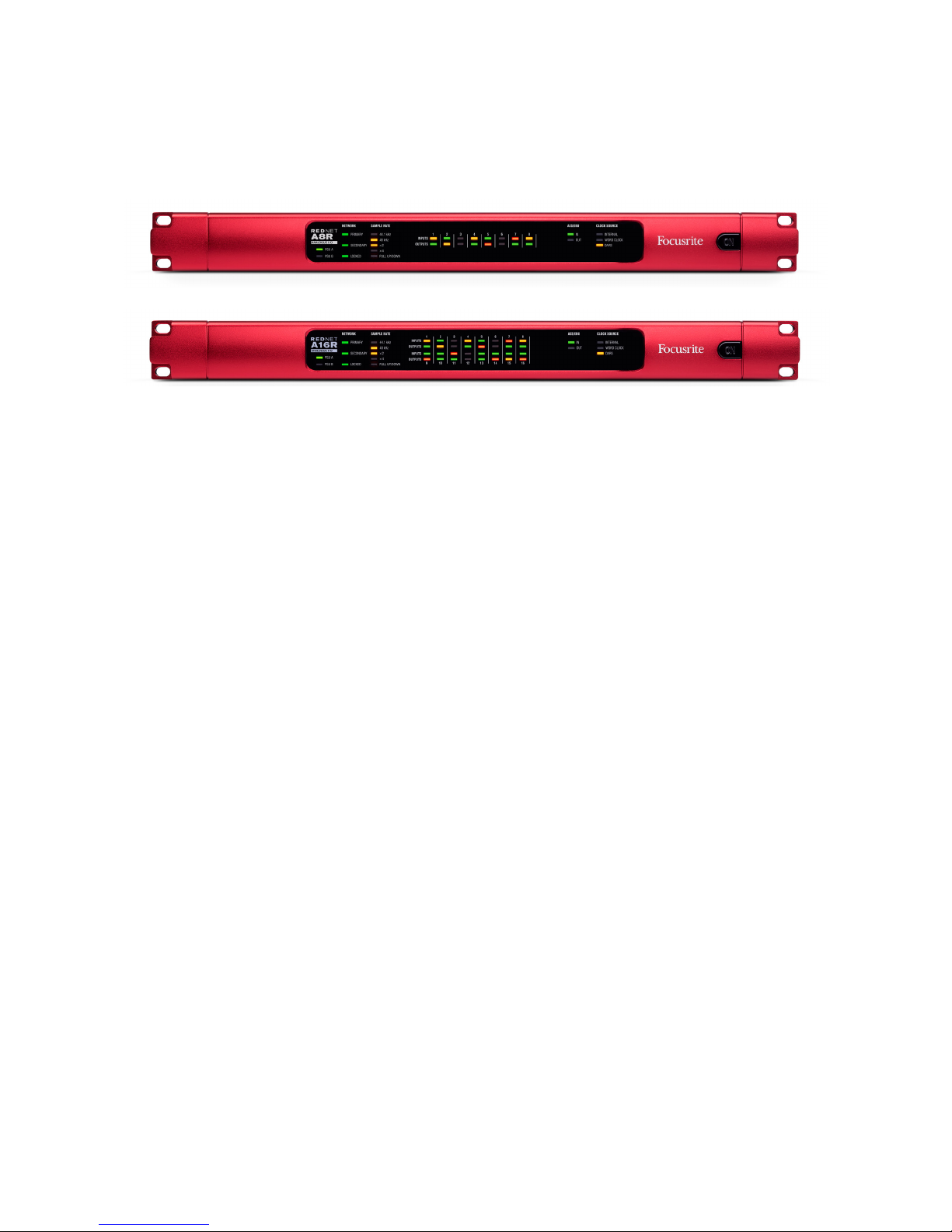
RedNet A8R
RedNet A16R
5
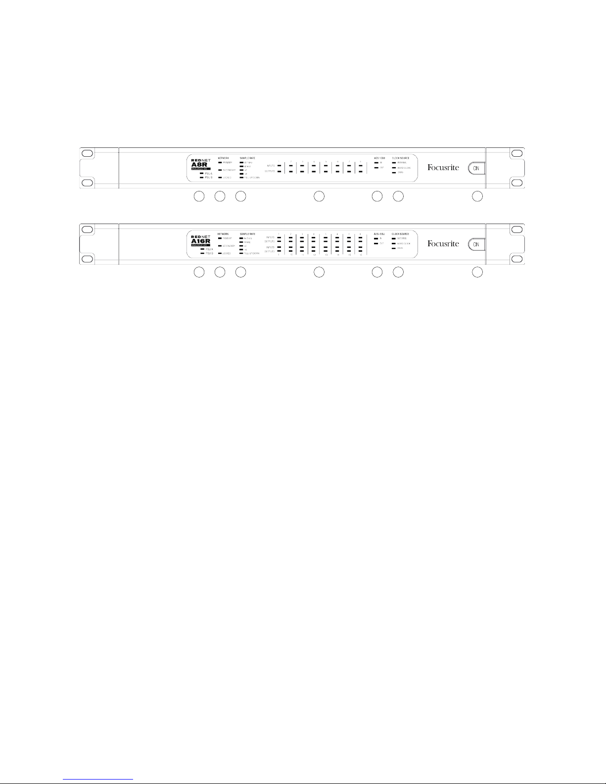
INSTALLATION GUIDE
RedNet A8R/A16R Connections and Features
Front Panels
1. AC Power Switch
2. Power Indicators:
• PSU A – Illuminates when an AC input is applied and all DC outputs are present.
• PSU B – Illuminates when an AC input is applied and all DC outputs are present.
When both supplies are functioning and have AC inputs PSU A will be the default supply.
3. RedNet Network Status Indicators:
• PRIMARY – Illuminates when the device is connected to an active Ethernet network. Also
illuminates to indicate network activity when operating in Switched mode on either port.
• SECONDARY – Illuminates when the device is connected to an active Ethernet network.
Not used when operating in Switched mode.
• LOCKED – Illuminates when a valid sync signal is received from the network, or when the
RedNet A8R/A16R unit is the Network Master. Flashes if external clock is selected but
not connected.
4. RedNet Sample Rate Indicators
Five orange indicators: 44.1 kHz, 48 kHz, x2 (multiple of 44.1 or 48), x4 (multiple of 44.1 or 48)
and sample rate PULL UP/DOWN. These Indicators illuminate individually or in combination
to indicate the sample rate being used. For example, for a 96kHz Pull Up/Down setting, the
48kHz, x2 and Pull Up/Down indicators will illuminate.
5. Signal Level Indicators:
• INPUTS – Tri-colour LEDs indicate audio signal levels at the inputs to the network:
Green: Signal present (illuminates at -42 dBFS)
Orange: -6 dBFS
Red: 0 dBFS
Continued...
RedNet A8R
RedNet A16R
12 3 4 5 6 7
12 3 4 5 6 7
6
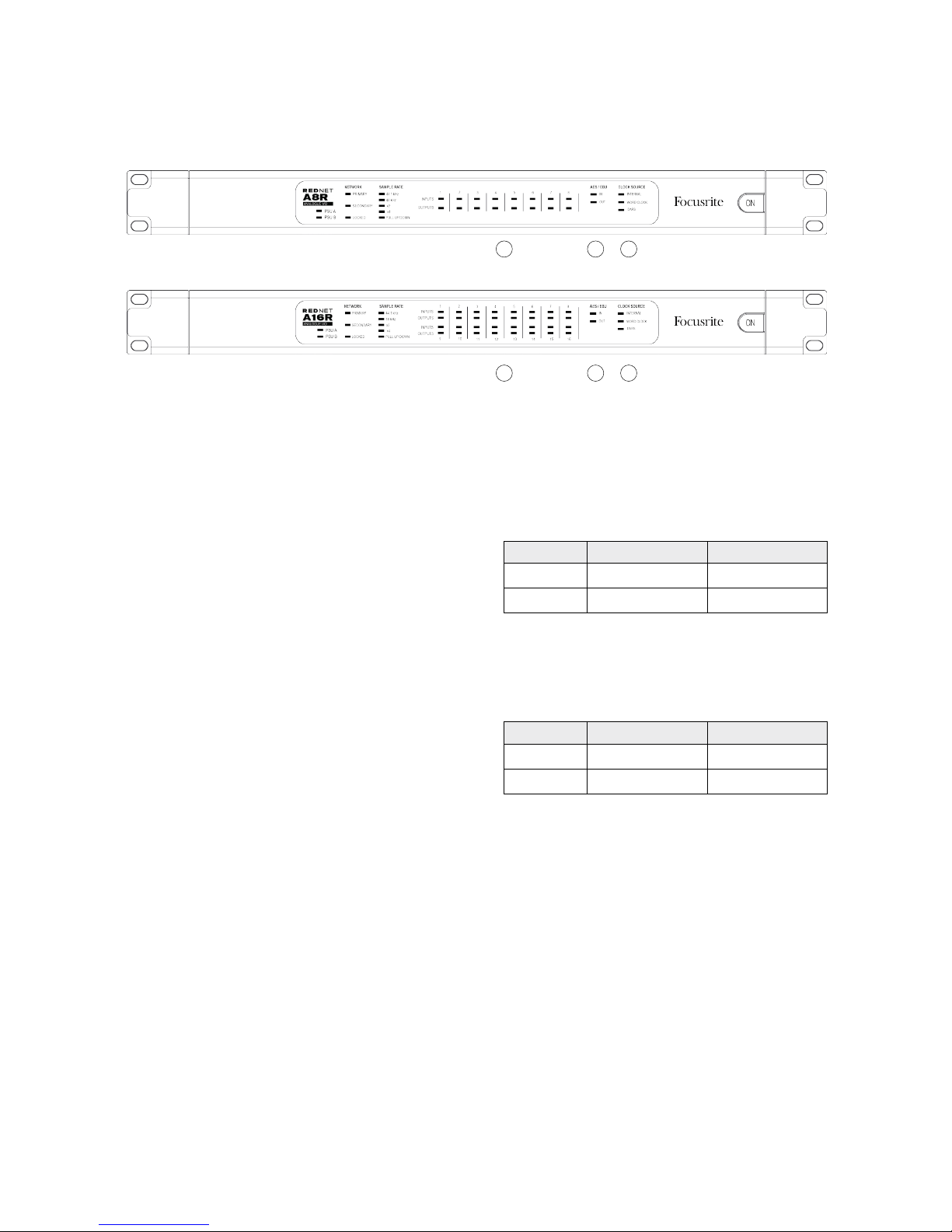
5. Signal Level Indicators:
• OUTPUTS – Tri-colour LEDs indicate audio signal levels at the outputs from the network:
Green: Signal present (illuminates at -42 dBFS)
Orange: -6 dBFS
Red: 0 dBFS
[When a RedNet A16R unit is operating at
quad sample rates, the indication for LEDs
15 and 16 will depend on the signal mode
selected.]
6. AES/EBU Signal Presence Indicators
Green LEDs indicate if an AES/EBU signal is present IN to the network, and OUT from
the network; each illuminates at -126
dBFS.
[When a RedNet A16R unit is operating at quad
sample rates, the IN and OUT LEDs don’t illuminate
if Analogue mode has been selected.]
7. RedNet Clock Source Indicators
Three orange indicators: Internal, Word Clock (BNC input) and DARS (XLR input). Whichever
is lit identifies the clock reference being used. When an incoming clock source is invalid, the
‘Locked’ indicator will flash to indicate that the unit has reverted to using its internal clock.
RedNet A8R
RedNet A16R
Front Panels . . . Continued
6 75
6 75
Mode LED 15 LED 16
Analogue Analogue ch 15 Analogue ch 16
AES/EBU AES/EBU Left AES/EBU Right
Mode ‘IN’ LED ‘OUT’ LED
Analogue Off Off
AES/EBU Analogue ch 15/16 Analogue ch 15/16
 Loading...