

Page 1
Red 8Pre
64 in / 64 out Thunderbolt™ 2 audio interface – with Pro Tools | HD
and Dante™ network audio connectivity
User Guide
FFFA001457-01
www.focusrite.com
Page 2

CONTENTS
About this User Guide .......................................................4
Box Contents...............................................................4
System Requirements .......................................................4
Introduction..................................................................5
Key Features...................................................................5
System Block Diagram ..........................................................6
Red 8Pre Controls and Connections ...........................................7
Front Panel ....................................................................7
Rear Panel ....................................................................8
Physical Characteristics .....................................................9
Power Requirements ........................................................9
Operation...................................................................10
INPUTS .................................................................. 10
Analogue Inputs ...........................................................10
Input Controls .............................................................10
Preamp Overview Screen .......................................................10
Preamp Focus Screen ..........................................................10
Input Configuration.........................................................11
Input Functions................................................................11
Encoder Toggle Function........................................................12
Line Inputs 9 – 16 ..........................................................12
DIGITAL INPUTS........................................................... 13
ADAT ....................................................................13
S/PDIF ...................................................................13
Loopback Input ............................................................13
DANTE CONNECTION....................................................... 13
MONITORING .............................................................14
Monitors .................................................................14
Monitor Display ...............................................................14
Mute and Dim .................................................................14
Headphones ..............................................................14
METER DISPLAY........................................................... 15
Meter Source Selection .........................................................15
ANALOGUE OUTPUTS ...................................................... 15
THUNDERBOLT CONNECTION ...............................................16
Logic Pro X Setup ..........................................................16
2
Page 3

PRO TOOLS CONNECTION................................................... 17
Using Red 8Pre with other Pro Tools | HD interfaces .............................17
Loop Sync ....................................................................17
Pro Tools Setup............................................................18
Global Settings ..............................................................19
Host .....................................................................19
Sync .....................................................................19
Retain....................................................................19
Routing ..................................................................19
Focusrite Control ...........................................................20
System Requirements ......................................................20
Software Installation .......................................................20
Operation.................................................................20
Device Settings GUI ........................................................21
Monitor Controls ..............................................................21
Input Routing..............................................................22
Appendices..................................................................23
Appendix 1 – Connector Pinouts ..............................................23
DB25 (AES59) Connector ........................................................23
1/4” Jack Connectors...........................................................23
Pro Tools Interface ............................................................24
BNC Connectors...............................................................24
Ethernet Connector ............................................................24
Appendix 2 – Channel Allocation..............................................25
Sample Rate: 44.1 / 48 kHz . . . . . . . . . . . . . . . . . . . . . . . . . . . . . . . . . . . . . . . . . . . . . . . . . . . . . .25
Sample Rate: 88.2 / 96 kHz . . . . . . . . . . . . . . . . . . . . . . . . . . . . . . . . . . . . . . . . . . . . . . . . . . . . . .26
Sample Rate: 176.4 / 192 kHz ....................................................27
Appendix 3 – Air information .................................................28
Performance and Specications ..............................................29
Focusrite Red 8Pre Warranty and Service ......................................32
Registering Your Product....................................................32
Customer Support and Unit Servicing .........................................32
Troubleshooting ...........................................................32
3
Page 4

About this User Guide
This user guide applies to the Red 8Pre Thunderbolt Interface. It provides information about installing
and operating the unit and how it can be connected into your home or studio system.
Box Contents
• Red 8Pre unit
• IEC AC mains cable
• 2m Thunderbolt cable
• Product registration card – which provides the following important information:
Unit serial number
Bundle code (for registering your product and for accessing your free software)
System Requirements
• Apple Mac with at least one Thunderbolt or Thunderbolt 2 port, or Pro Tools | HD system for
DigiLink connection
• Internet connection for downloading and installing software and driver
Thunderbolt™ and the Thunderbolt logo are trademarks of Intel Corporation in the U.S. and/or other countries.
Dante™ and Audinate™ are registered trademarks of Audinate Pty Ltd.
4
Page 5
INTRODUCTION
Thank you for purchasing the Focusrite Red 8Pre.
Red 8Pre is a dual Thunderbolt™ & Pro Tools | HD audio interface and preamplifier, suitable for a
wide range of audio integration applications.
The Red 8Pre features Mic, Line and Instrument analogue inputs and 22 analogue output channels –
including independent loudspeaker and headphone monitoring plus an LCD meter display. Red 8Pre
provides an interface for Pro Tools | HD equipped workstations and, with its built-in Dante™ card, is
ready for networked audio expansion via the dual Ethernet ports.
Key Features
• Two Thunderbolt 2 Interface ports for direct or chained connection.
• 16 line-level input and output signals via DB25 connectors on the rear panel.
• Eight remote controlled microphone preamps providing up to 63dB of gain, each with phantom
power, high-pass filter, phase-reverse and ‘Air’ mode. See Appendix 3 on p.28 for further information.
• Two instrument inputs accessed via front-mounted 1/4” jacks.
• Analogue monitoring via dedicated balanced 1/4” jack outputs on the rear panel, plus two
independent headphone outputs on the front panel.
• Digital devices can be accommodated via the S/PDIF and dual ADAT I/O connections.
• Two Primary Mini DigiLink connectors provide up to 64 input and 64 output channels of I/O to Pro
Tools | HD.
• Dual Ethernet ports provide up to 32 x 32 channels of networked audio expansion over Dante.
• BNC connectors allow Red 8Pre to sync or slave to external devices via Word Clock or Loop Sync.
• Permanent 8-channel LCD meter display – selectable to show all input types.
• Simple host and sync selection setup.
• Focusrite Control application allows full remote hardware operation, plus mixing and routing
control.
5
Page 6
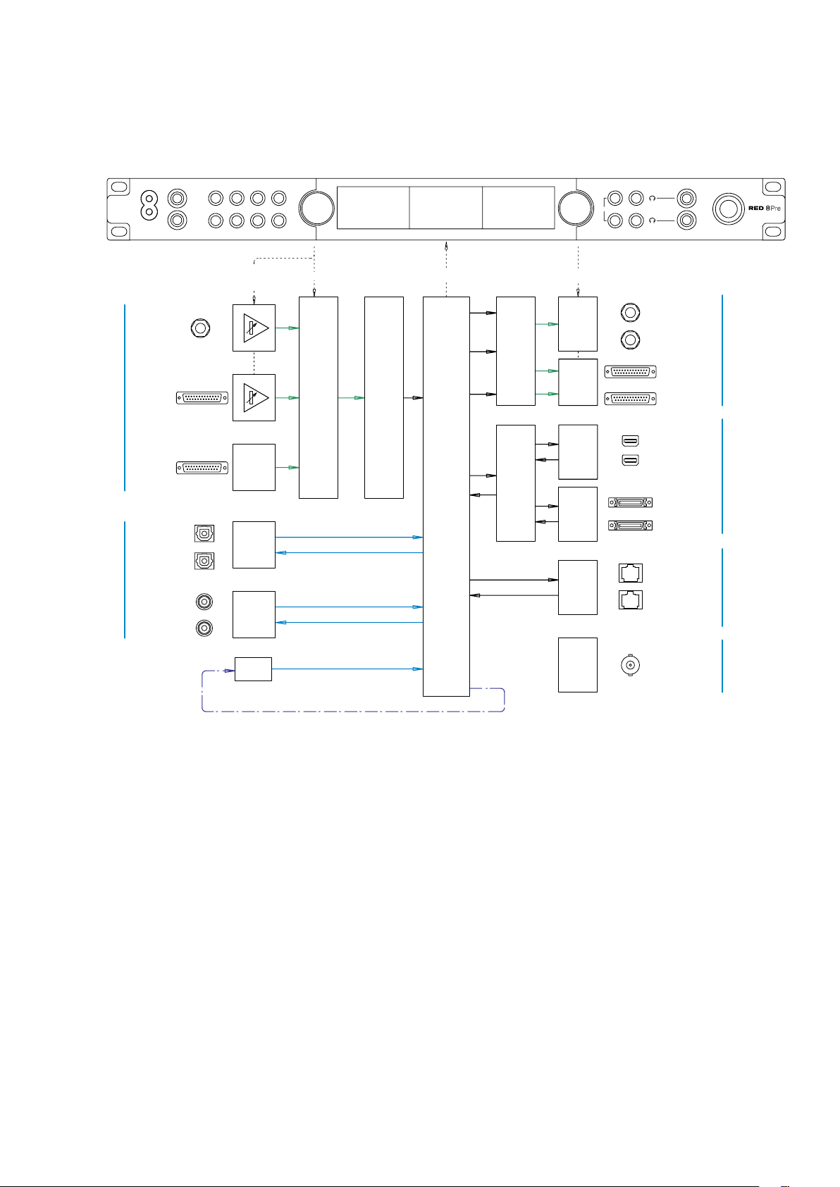
System Block Diagram
Analogue
Inputs
Digital
I/O
Focusrite
Instrument
1-2
Mic/Line
1-8
Line
9-16
ADAT 1
1-8
ADAT 2
9-16
S/PDIF In
S/PDIF Out
INST
I
2
2
I
SLCT
4
3
Input Function
& Gain
2
2
4
4
Input Select Output ControlMeters
1-2
16
1-8
9-16
A-D
16
16
2
2
OT
MT
MONITO
I
2
Monitor
1-2
Headphones
1&2
Line
3-10
Line
11-18
Analogue
Outputs
GLOAL
2
D-A
8
8
Thunderbolt
64
Host
Select
64
DAW
Pro Tools
32
32
Dante
Network
Network
Loopback In
2
Word Clock I/O
Loop Sync I/O
Numbers indicating channel capacities relate to a 44.1/48 kHz sample rate. Refer to the Channel I/O tables
on pages 25–27 for the channel counts at higher sample rates.
Clock
6
Page 7

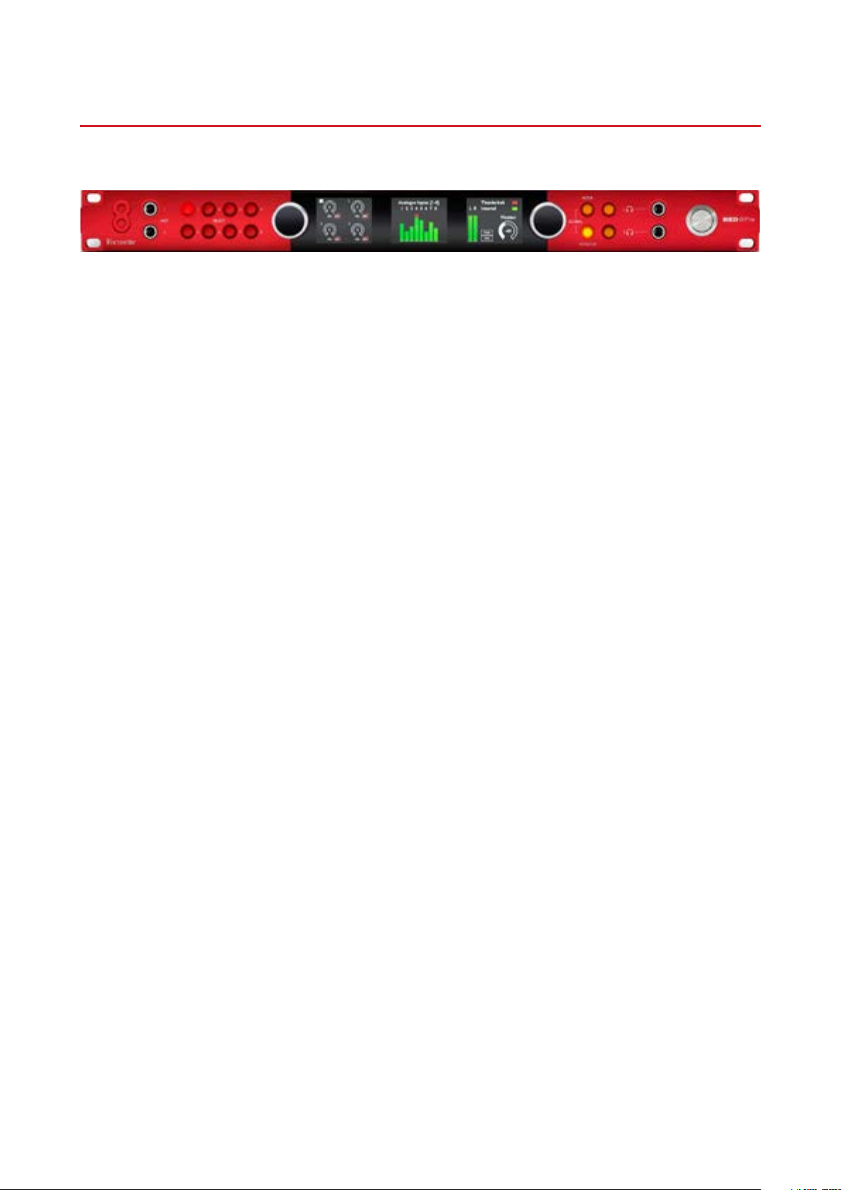
Red 8Pre Controls and Connections
2
6
4
8
I
2
INST
GLOBAL
MONITOR
METER
I
2
Focusrite
SELECT
I
5
3
7
Front Panel
Instrument
Inputs
Input
Encoder
Input Select
Buttons
Input
Display
Level Meter
Display
Output
Display
Output
Encoder
Meter & Monitor
Buttons
H/phone
Select
H/phone
Outputs
Power Switch
• Instrument Inputs. Two high-impedance inputs on 1/4” jack sockets.
• Input Select buttons provide direct access to the menu settings for analogue input channels 1–8.
• The Input Encoder and its associated Input Display is used to select and adjust the configuration
menu settings for the input channels; it also functions as the input gain control for inputs 1–8.
• The Level Meter Display is an eight channel, switchable LCD meter which is able to display
groups of input signals.
• The Output Encoder functions as the volume control for the monitor and headphone outputs. It
is also used to configure the global system settings, control the meter selection and select the
monitor dim and mute features. Its function is determined by the adjacent Monitor, Meter and
Headphone Select buttons.
• The Meter button calls up the selection menu for the level meters onto the Output Display.
• The Monitor button assigns the Output Encoder to the monitor loudspeaker functions.
Pressing the Meter and Monitor buttons simultaneously enters Red 8Pre’s Global conguration menu, where
host, clock, power-up and network settings are assigned.
• The Headphone 1 and 2 buttons assign the Output Encoder to the selected headphone control
functions.
• Headphone Outputs are standard 1/4” TRS jacks.
7
Page 8
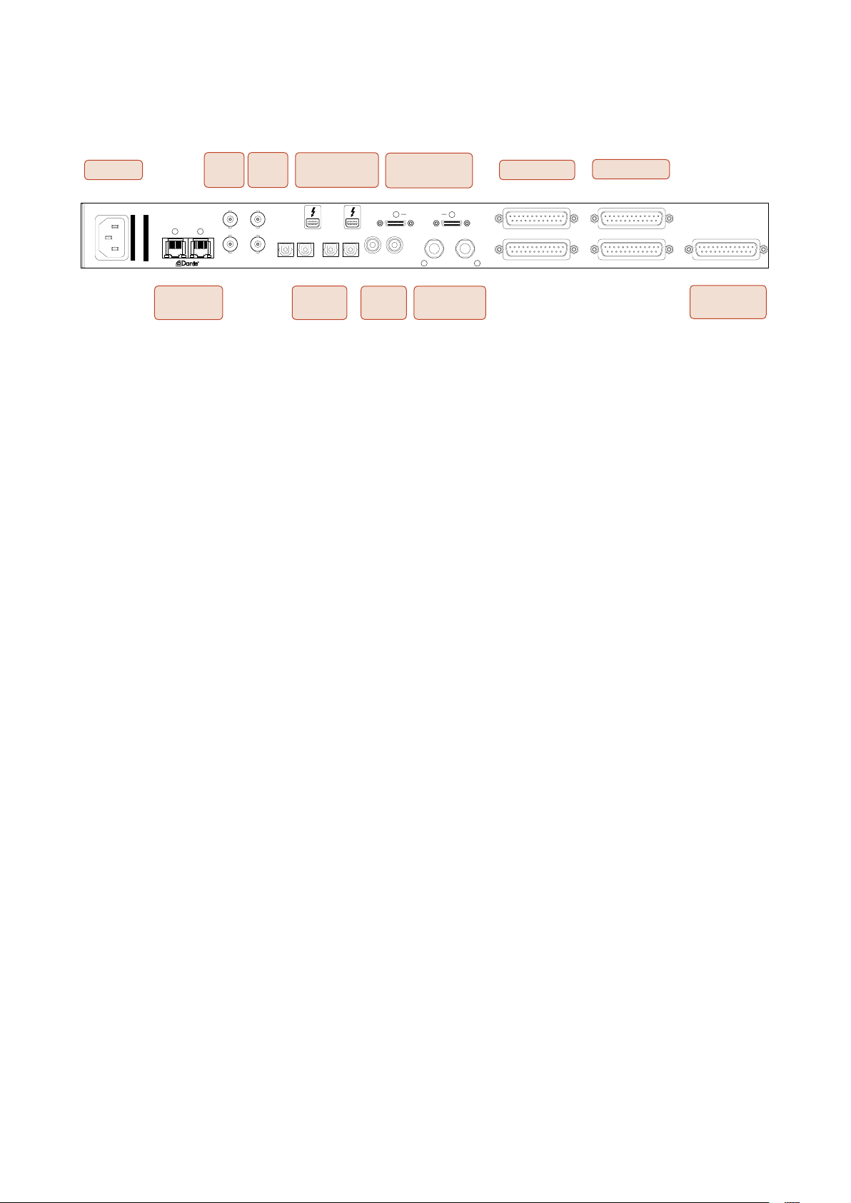
Rear Panel
CLOCK
SYNC
MONITOR OUTPUTS
MIC INPUTS 1-8
AC Inlet
AC ONLY 100-20 060 6W
WARNING
THIS EQUIPMENT MUST BE
Focusrite
Focusrite Audio Engineering Ltd
DAIMENTATION
ARIN
A A TERRE PAR E CORDON
CET APPAREI DOIT ETRE MIS
EARTHED BY THE POWER CORD
Network
1 2
Dante
Word
Clock
WORD
Loop
Sync
LOOP
Thunderbolt 2
IN
OUT
IN OUT IN OUT
OPTICAL 9-16 OPTICAL 1-8
ADAT
I/O x2
Interface
Pro Tools | HD
1
IN OUT
SPDIF
S/PDIF
I/O
Interface
PRIMARY PORT
R L
L/R Monitor
Outputs
Line Outputs
2
LINE OUTPUTS 11-18
LINE OUTPUTS 3-10
Line Inputs
LINE INPUTS 9-16
LINE INPUTS 1-8
Microphone
Inputs
• AC Mains Inlet. Standard IEC receptacle for connection of AC mains. Red 8Pre features a
‘Universal’ PSU, enabling it to operate on any supply voltage between 100 V and 240 V AC.
• Word Clock – Input allows synchronisation to word clock.
• Word Clock – Output provides an output of the chosen system clock reference.
• Loop Sync I/O sockets allow Red 8Pre to integrate with a standard Pro Tools system I/O chain.
• Dual Thunderbolt 2 Connection. Two ports allow either direct or chained connection to your
workstation.
• Pro Tools | HD Interface. Two Mini DigiLink Primary connectors; use Mini DigiLink cables to
connect to a Pro Tools | HD HDX PCIe card or Pro Tools | HD Native system.
• Line Outputs on two 25-way DB25 female connectors.
DB25 connectors are wired according to the AES59 Standard (also known as the TASCAM Analogue standard).
• Line Inputs on two 25-way DB25 female connectors.
Note that Line input circuits 1–8 can be re-assigned to the Microphone and/or Instrument connectors so may not
always be available on this connector. See page 11 for further information.
• Microphone Inputs on 25-way DB25 female connector.
NB. A DB25 male to XLR-3 female 8-way adapter loom will be required for mic leads with individual XLRs.
• Network. Two RJ45 Ethernet connectors for the Dante network. The connectors form an integral
2-port switch, allowing either to be used on the network.
• ADAT I/O 1 and 2. Two independent 8-channel ADAT optical inputs and outputs using standard
TOSLINK connectors. Optical I/O 1 can also be used in ‘Optical S/PDIF’ mode.
• S/PDIF I/O. 2-channel digital interface on RCA (phono) connectors.
• Monitor Outputs. Balanced 1/4” TRS jacks for connection of Left and Right monitor loudspeakers.
Outputs are at line level so unpowered speakers will require external amplification.
See Appendix 1, page 23 for the connector pinouts.
8
Page 9
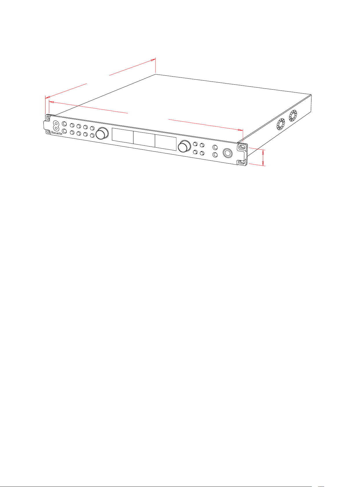
Physical Characteristics
300mm / 11.8”
465.0mm / 18.3”
31.8mm / 1.25”
Red 8Pre dimensions are illustrated in the diagram above.
Red 8Pre requires 1U of vertical rack space and at least 360mm of rack depth, to allow for cables. Red
8Pre weighs 5.14kg and for installations in a fixed environment (eg., a studio), the front-panel rack
mountings will provide adequate support. However, if the units are to be used in a mobile situation
(eg., flight-cased for touring, etc.), it is recommended that side support rails or shelves are used
within the rack.
Cooling is by fan assistance from side to side; the fans used are low-speed and low-noise. Do not
mount the unit immediately above any other equipment which generates significant heat, for example,
a power amplifier. Also, ensure that when mounted in a rack, the side vents are not obstructed.
Note. The maximum operating environmental temperature is 40°C / 104°F.
Power Requirements
Red 8Pre is mains-powered. It incorporates a ‘Universal’ power supply which can operate on any AC
mains voltage from 100 V to 240 V. The AC connection is via a standard 3-pin IEC connector on the
rear panel.
A mating IEC cable is supplied with the unit – this should be terminated with a mains plug of the
correct type for your country.
The AC power consumption of the Red 8Pre is 65W.
Please note that there are no fuses in Red 8Pre, or other user-replaceable components of any type.
Please refer all servicing issues to the Customer Support Team (see “Customer Support and Unit
Servicing” on page 32).
9
Page 10
OPERATION
Line
+48V
I2
Phase
HPF
Air
5
Line
48
12
Line
48
2
31
Mic
48
3
50
Mic
4
12
I
48
Inputs
Red 8Pre has the capacity to accommodate sixteen analogue inputs, two independent 8-channel
ADAT inputs, a 2-channel S/PDIF input plus 32 Dante input channels. (Additionally, when in Thunderbolt
host mode, an internal 2-channel loopback signal can be added as an extra stereo input – see page 13 for details.)
Analogue Inputs
Analogue input channels 1 to 8 can be assigned to the Instrument, Microphone or Line input
connectors as follows: Input channels 1 and 2 are selectable as Instrument, Microphone or Line
level; Inputs 3 to 8 are mic or line selectable. Input channels 9 – 16 are fixed-gain line level only.
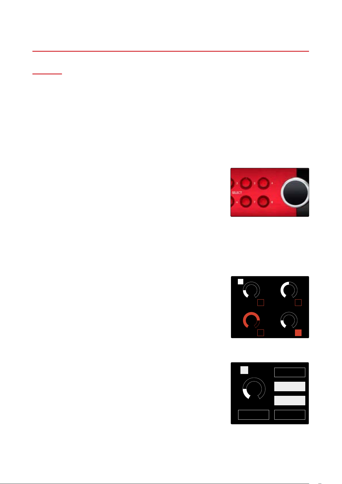
Input Controls
Input selection and configuration for channels 1 to 8 is carried out
using the Preamp Select buttons and the Input Encoder.
The illuminated Select button identifies the channel being controlled.
• Pressing a Select button makes that channel the active channel
Power-up always selects channel 1
• The Input Encoder acts as the gain control for the active channel
Select Buttons / Input Encoder
• Pushing (’clicking’) the Input Encoder selects menu options or
operates the Toggle function (see page 12)
Preamp Overview Screen
This is the default display for input channels 1 – 4 or 5 – 8. It shows
at-a-glance the current input type, gain value and phantom power
status for either group of four channels.
The highlighted number indicates the active channel (as shown for
channel 1).
Note: a clipping channel will be indicated by its gain level bar changing to red (as
shown for channel 3) – reset by pressing the channel’s Select button.
Preamp Focus Screen
Pressing an input Select button brings up the Focus screen which
provides additional detail about that channel’s current settings.
If no changes are made within approximately 3 seconds, the display
will revert to the Overview screen.
Preamp Overview Screen
In the example shown, channel 5 has the phase and HPF functions enabled.
Preamp Focus Screen
10
Page 11

Input Configuration
+48V
Phase
HPF
Air
Link
Back
Line
On Off
Type
OffOn
On
On
Off
Off
On Off
+48V
Phase
HPF
Air
Link
Back
Line
Type
OffOn
On Off
On Off
On
On
Off
Off
The settings for an input channel – its input type and function options
– are selected via the Config Menu.
• To enter the Config Menu, press-and-hold a channel’s Select
button
To exit this screen, press any of the channel Select buttons (or, rotate
the Input Encoder to the ‘Back’ option and then click).
Channel Config Menu Screen
Input Functions
The following channel functions can be set, or toggled On/Off, from the Config Menu screen:
• Type selects the signal input type to be used for the channel:
For channels 1 & 2: Instrument › Mic › Line
For channels 3 to 8: Mic › Line
• +48V enables phantom power for the selected microphone input
• Phase applies phase inversion to the selected channel
• HPF switches in the 80Hz high-pass filter
• Air changes the microphone, line and instrument input characteristics to ‘Air’ mode. See Appendix
3, page 27 for further information
• Link combines odd/even channels (1-2, 3-4, 5-6 and 7-8) so they operate as a stereo pair. When
linked, Gain and Input Type changes to either of the paired channels will be applied to both
When linking channel pairs, the existing gain and input type settings for the odd channel will be applied to the
even channel – 48V, HPF and ‘Air’ will not be affected by stereo link
• Back exits the Config Menu screen and returns to the Overview display
Pressing any of the channel Select buttons will also exit the Cong menu screen
To change an input function:
1 Rotate the Input Encoder until the required function is
highlighted
2 Push the Input Encoder to step through the input types or to
toggle On/Off
Channel Function Selection
11
Page 12

Encoder Toggle Function
+48V
Phase
HPF
Air
Link
Back
Line
On Off
Type
OffOn
On
On
Off
Off
On Off
Stored
Press Function
Phase
The Input Encoder can be programmed to toggle any one of the input
functions with a single push (ie., without having to enter the Config
Menu screen). This can be very useful when, for example, experimenting with
microphone phasing.
To select a function for the Input Encoder toggle feature:
1 Enter the Config Menu screen
2 Scroll to the function required for the toggle feature
3 Press-and-hold the Input Encoder until the confirmation
message appears in the input display
The selected function will now toggle on/off* each time the Input
Encoder is clicked.
*If ‘Type’ is selected, clicking the Input Encoder will step through the available
inputs.
Input Encoder Toggle Confirmation
Line Inputs 9 – 16
Line input channels 9 to 16 are always available on the DB25 connector.
The gain of these channels is not variable.
An input signal level of +27 dBu corresponds to 0 dBFS.
LINE INPUTS 9-16
12
Page 13

Digital Inputs
OPTICAL 9-16 OPTICAL 1-8
IN OUT
SPDIF
MONITOR OUTPUTS
PRIMARY PORT
LINE INPUTS 1-8
LINE OUTPUTS 3-10
MIC INPUTS
1234
1
2
R L
Focusrite
WORD
CLOCK
LOOP
SYNC
OPTICAL 9-16 OPTICAL 1-8
IN OUT IN OUT
IN OUT
SPDIF
MONITOR OUTPUTS
PRIMARY PORT
LINE INPUTS 1-8
LINE OUTPUTS 3-10
1
2
R L
IN
OUT
SPDIF
MONITOR OUTPUTS
PRIMARY PORT
LINE INPUTS 1-8
LINE OUTPUTS 3-10
MIC INPUTS
1234
1
2
R L
ADAT
ADAT inputs 1 and 2 are accessed via the rear panel connectors. Signals
will be available if the source is connected and the system is synced to a
common clock.
Each In/Out connection provides:
• 8ch at 44.1 / 48 kHz
• 4ch at 88.2 / 96 kHz (SMUX)
• 2ch at 176.4 / 192 kHz (SMUXII)
S/PDIF
A two-channel S/PDIF I/O connection is accessed via the RCA/Phono connectors
on the rear panel, or via the optical 1 TOSLINK connectors.
Loopback Input
The Red 8Pre’s virtual loopback inputs allow you to record any mix within
Focusrite Control back into your DAW. This could be the audio output of
another software application, or an entire monitor mix within Focusrite
Control including analogue or digital inputs mixed with any playback signals
you wish to capture in your DAW.
IN OUT IN OUT
IN OUT
Loopback uses the Red 8Pre’s virtual inputs, which have no physical
connectors on the hardware interface itself, but may be selected in the
DAW as signal sources for recording in the same way as any other.
Focusrite Control –
Loopback Signal Routing
For Focusrite Control information, see page 20.
Dante Connection
Two switched RJ45 connectors for the Dante network are located on the rear
panel. Use a standard Cat 5e or Cat 6 network cable to connect to the Dante
audio network.
Incorporated into each socket are LEDs which illuminate to indicate a valid
network connection and network activity.
Note that the Dante connectors are congured for a single, switched network – they cannot be used as primary and
secondary ports on a redundant network.
For more information on Dante networks, see Audinate’s website: http://www.audinate.com/
Note that on power-up, the settings for Preferred Master and External Clock will return to the state prior to shutting
the unit down. - this ensures that power cycling a device doesn’t affect the rest of the network when the Red interface
is not the Dante Grand Master.
1 2
On a clock change, either from the front panel or Focusrite Control, both Preferred Master and External Clock are
set - this does not protect a network from a deliberate clock source change affecting the whole network.
13
Page 14

Monitoring
Internal
L R
-65
Thunderbolt
Mute
Dim
Monitor
Mute
Dim
On Off
On Off
Back
Mute
Press Function
Stored
Monitors
Monitor outputs, at line level, are provided via the 1/4” jack outputs
on the rear panel.
• The Output Encoder will adjust the monitor output level
whenever the Monitor button is illuminated
Monitor Display
The monitor display shows the current volume level and whether
either Dim or Mute is active. ‘Dim’ attenuates the signal by 18dB.
The L/R meter display shows a pre-fade level (the signal level
present before the Output Encoder).
The display also shows the Global Host and Sync settings and their
lock status flags (see ‘Global Settings’ on page 19).
Mute and Dim
Mute and Dim functions are individually enabled via the Monitor
Setup menu. Additionally, the Output Encoder can be programmed
to toggle either the Dim or Mute function when clicked.
Monitor Display
Menu activation:
1 Press-and-hold the Monitor button to enter the Setup menu
2 Rotate the Output Encoder to highlight either Dim or Mute
3 Click to select On or Off
4 To exit, press Monitor again (or select the ‘Back’ option)
Toggle Function programming:
1 Enter the Monitor Setup menu as above
2 Rotate to highlight the function to be programmed
3 Press-and-hold the Output Encoder until the confirmation
message appears
The selected function will now toggle on/off each time the Output
Encoder is clicked.
Headphones
Two independent stereo headphone outputs are available on the
front panel.
• To adjust a headphone’s volume level – or to activate Dim or Mute
for that output – press one of the Headphone Select buttons
Also see: Focusrite Control – Monitor Controls, on page 21
Monitor Setup Menu
Encoder Toggle Confirmation
For Dim and Mute activation and programming, refer to the ‘Mute and Dim’
section above but substitute ‘Monitor button’ with the appropriate Headphone
Select button.
14
Headphone Select Buttons
Page 15

Meter Display
Analogue Inputs [I-8]
I 2 3 4 5 6 7 8
ADAT 1 [1-8]
Network Inputs [1-8]
SPDIF Inputs [1-2]
Analogue Inputs [1-8]
Network Inputs [9-16]
ADAT 2 [9-16]
Analogue Inputs [9-16]
MIC INPUTS 1-8
LINE INPUTS 9-16
LINE INPUTS 1-8
The centre LCD screen displays up to eight level meters. These
indicate the internal signal level, after A-D conversion, with 0 dBFS
being at full scale.
A red clip indicator is displayed on channels that reach clipping
point.
Meter Source Selection
To select the source for the 8-channel LCD display:
1 Press the Meter button on the front panel to access the Meter
Source-List
2 Use the Output Encoder to scroll to the required input
3 Click the Output Encoder to make the selection
4 Press Monitor or one of the Headphone Select buttons to exit
Analogue Outputs
16 analogue outputs are provided on the two DB25 female connectors on
the rear panel.
Analogue outputs are at fixed gain. 0 dBFS corresponds to a signal
level of +18 dBu.
Meter Source List
LINE OUTPUTS 11-18
LINE OUTPUTS 3-10
15
Page 16

Thunderbolt Connection
PRIMARY PORT
1
2
Confirm that Red 8Pre’s Host setting is set to ‘Thunderbolt’, see Global Host Settings on page 19.
Two Thunderbolt 2 connectors are located on the rear panel.
Connect to the host or into the chain using standard Thunderbolt cables
(one supplied).
See appendix 2 on pages 25–27 for the channel I/O allocation tables.
Logic Pro X Setup
• From the menu bar, go to: Logic Pro X > Preferences > Audio...
• Under the Devices tab, set: Input Devices and Output Devices to ‘Focusrite Thunderbolt’
16
Page 17

Pro Tools Connection
Confirm that Red 8Pre’s Host setting is set to ‘Pro Tools’, see Global Host Settings on page 19.
Connect both rear panel PRIMARY ports to a Pro Tools | HDX card using Mini DigiLink cables.
Each Pro Tools | HDX PCI/PCIe card provides two Mini DigiLink ports (giving the card a capacity of 64
inputs and 64 outputs), thus one Red 8Pre may be connected to each card.
PRIMARY PORT
1
A Red 8Pre will appear as four devices in Pro Tools:
A: 1-16 (Port 1)
B: 1-16 (Port 1)
C: 1-16 (Port 2)
D: 1-16 (Port 2)
Mini DigiLink Cables
A maximum of 3* Red 8Pre units can be connected, giving a
total I/O capability of 174 inputs and 192 outputs.
* One Red 8Pre if using an HD Native system.
Note that both Red 8Pre ports are Primar y connectors; this means that an additional Pro Tools interface cannot be
added in series – Red 8Pre does not operate in Expansion mode
Using Red 8Pre with other Pro Tools | HD interfaces
2
PRIMARY PORT
1
2
Pro Tools | HD I/O audio interfaces may be used on the same
Pro Tools system as Red 8Pre. Pro Tools interface units can
be added by using additional Pro Tools | HDX PCIe interface
cards.
Connection to a Pro Tools | HD system would require the use of DigiLink
-to- Mini DigiLink adapter cables.
Loop Sync
It is important when using additional I/O devices that the
Loop Sync connection is complete between all units:
• Using 75Ω BNC cables, connect each LOOP SYNC OUT
connector to the LOOP SYNC IN connector on the next
I/O unit
• Complete the chain by connecting LOOP SYNC OUT on
the final I/O unit back to LOOP SYNC IN on the first unit
Focusrite
PRIMARY
PRIMARY
EXPANSION
EXPANSION
IN
OUT
LOOP
SYNC
LOOP
SYNC
IN
OUT
LOOP
SYNC
IN
OUT
17
Page 18

Pro Tools Setup
• From the Pro Tools menu bar, go to:
Setup > Playback Engine...
• In the Playback Engine menu popup, select: ‘HDX’ or ‘HD Native’, as
appropriate for your system
The following steps are optional but will simplify signal routing:
• From the menu bar, go to: Setup > I/O Setup...
• Ensure your input and output routing tables are routed as follows by selecting the Default tab at
the bottom left of the page.
Note
1. The number of input and output channels available is dependent on the sample frequency (see channel allocation
tables in Appendix 2, pages 25–27
18
Page 19

GLOBAL SETTINGS
Sync
Retain
Back
Thunderbolt
Host
Internal
Preamp +48VPreamp
Routing Advanced Routing
Press the Meter and Monitor buttons simultaneously to enter the
global settings menu.
• Rotate the Output Encoder to select a menu item
• Click the Output Encoder to step through the available options
To exit the Global settings screen press the Monitor button (or select
the ‘Back’ option).
Host
Selects the connection used for the DAW host:
• Thunderbolt
• Pro Tools
The Lock status in the Monitor display will show green when locked
to the DAW host.
Global Settings Menu
Note: changing Host type will cause the device to perform a power reset.
L R
Sync
Thunderbolt
Internal
Monitor
Selects the Red 8Pre’s sync source:
-65
• Internal – internally generated. This is the default selection
Mute
Dim
• Word Clock – received via the BNC Word Clock In connector
• ADAT 1 – received via the rear Optical In 1-8 connector
Host and Sync Settings and
Lock Status
• ADAT 2 – received via the rear Optical In 9-16 connector
• S/PDIF – received via either the rear RCA In connector, or Optical port 1
• Dante – provided by the Dante network connection
• Loop Sync – only applicable when in Pro Tools host mode
When sync is established, the Lock status will change to green. A red status indicates no sync.
Retain
Choose whether the previous phantom power settings are restored on power-up:
• Preamp – all previous settings are returned except the 48V settings, which will be set to Off
• Preamp +48V – all previous settings are returned
Routing
• Advanced Routing – allows remote routing using the Dante Controller application
• Auto Routing – not currently implemented
19
Page 20

FOCUSRITE CONTROL
The Focusrite Control application provides remote control of all Red 8Pre’s front panel
hardware functions and system settings via a graphical interface on your DAW. Additionally
the application provides control of all input and output routing and mixing functions.
Please note: This manual includes information relating to Red 8Pre’s specic front panel controls and device settings. For
compactness, however, the Mixing and Routing operations are not included here but are fully described in the separate
‘Focusrite Control User Manual’; this manual can be downloaded at the following link:
https://focusrite.com/downloads?product=Red+8Pre
System Requirements
Please visit the following link for up-to-date information on computer and operating system
compatibility for Focusrite Control: Compatibility
Software Installation
The Focusrite Control application for Red 8Pre can be installed as follows:
• Using your browser, go to www.focusrite.com/register.
• Follow the on-screen instructions, entering the “Bundle Code” into the form where prompted.
Your Bundle Code can be found on the back of the Getting Started Guide packed with Red 8Pre.
• Enter the unit’s serial number, which can also be found on the back of the Getting Started Guide.
• You will then be able to access the “My Products” page, where Focusrite Control is available for
download, complete with activation codes where applicable.
• Download and install Focusrite Control, which contains the necessary drivers for your interface.
Follow all on-screen instructions.
• When the installation is complete, you will be prompted to restart your computer.
• After a restart, connect Red 8Pre to your computer with a Thunderbolt cable.
Operation
The software control screen is divided into three tabs:
Device Settings
Allows hardware configuration and control via a GUI. See next page for details.
Input Routing
With more channels available on Red 8Pre than the DAW I/O maximum of 64, Input Routing allows
the input channel allocation to be reconfigured so that any signals required can be made available –
even when operating at higher sample rates. See page 21 for details.
Output Mixing & Routing
Allows control of output routing and DAW allocation via a GUI. Please refer to the separate Focusrite
Control User Manual for full details – see link above.
20
Page 21

Device Settings GUI
Sync Indicator
Sample rate Clock Source
Channel Gain
Channel Function Input Type
S/PDIF Source Meter SourceHost Mode
Sync Indicator – will be illuminated if Red 8Pre is locked to a valid clock source
Channel Gain – sets the input gain on analogue channels 1 – 8. Click-and-drag to change
Channel Function – click to select an input function. See page 11 for Function descriptions
Input Type – click to select the input signal type. Also see page 11 for Type descriptions
Sample Rate – select from: 44.1kHz, 48kHz, 88.2kHz, 96kHz, 176.4kHz, 192kHz
Clock Source – Internal, S/PDIF, ADAT 1 & 2, Word Clock, Dante, Loop Sync (Pro Tools host mode)
S/PDIF Source – RCA, Optical
Meter Source – Internal, S/PDIF, ADAT 1 & 2
Host Mode – Thunderbolt or Pro Tools. Changing Host type will cause the device to perform a power reset
Monitor Controls
Click to select which output channels are being controlled by the unit’s Output Encoder:
• Monitors: Monitor L/R Outputs
• Monitors + 3-4: Monitor L/R Outputs + Line Outputs 3–4
• Monitors + 3-6: Monitor L/R Outputs + Line Outputs 3–6
• All: Monitor L/R Outputs + Line Outputs 3–18
21
Page 22

Input Routing
Because the number of channels available reduces when operating at higher sample rates, Input
Routing allows the channel order to be re-arranged so that all input signals required can be accessed.
Use each drop-down list in the table to move input channels in pairs. For example, in the image
below, ADAT inputs 5-6 are being sent to DAW channels 1–2. This means that when selecting inputs
1–2 on a track in a DAW, ADAT inputs 5-6 on the Red 8Pre will be recorded.
Each DAW input channel pair can be allocated independently.
Allocated Signals
(Drop-down List)
Allocated Signals
(Drop-down List)
Default – returns the routing to the standard layout defined in the routing tables.
Undo – cancels change made to the last input selection.
All three routing tables can be edited from the top left of the screen - this will allow for custom
configuration of each sample rate band.
22
Page 23

APPENDICES
Appendix 1 – Connector Pinouts
DB25 (AES59) Connector
Connector type: DB25 Female
Applies to: Microphone Inputs
Analogue Line Input / Line Output
113
25 14
Pin Signal
1 Channel 8 +
14 Channel 8 –
2 Ground
15 Channel 7 +
3 Channel 7 –
16 Ground
4 Channel 6 +
17 Channel 6 –
5 Ground
18 Channel 5 +
6 Channel 5
19 Ground
7 Channel 4 +
20 Channel 4 –
8 Ground
21 Channel 3 +
9 Channel 3 –
22 Ground
10 Channel 2 +
23 Channel 2 –
11 Ground
24 Channel 1 +
12 Channel 1 –
25 Ground
13 n/c
1/4” Jack Connectors
Connector type: Balanced socket
Applies to: Monitor Outputs
Connector type: Unbalanced socket
Applies to: Instrument Inputs
Tip Ring Sleeve
Balanced Jack
Tip Sleeve
Unbalanced Jack
Pin Signal
Tip Hot (+ve)
Ring Cold (–ve)
Sleeve Screen
23
Page 24

11
8
1
8
Appendix 1 – Connector Pinouts Continued...
Pro Tools Interface
Connector type: Mini DigiLink receptacle
Applies to: PRIMARY 1 & 2
BNC Connectors
Connector type: 75Ω BNC Socket
Applies to: WORD CLOCK IN/OUT
LOOP SYNC IN/OUT
Ethernet Connector
Connector type: RJ-45 receptacle
Applies to: Ethernet (Dante)
Pin Cat 6 Core
1 White + Orange
2 Orange
3 White + Green
4 Blue
5 White + Blue
6 Green
7 White + Brown
8 Brown
24
Page 25

Appendix 2 – Default
Channel Allocation
Sample Rate: 44.1 / 48 kHz
Inputs Outputs
1 Mic/Line/Inst
2 2
3
4 4
5 5
6 6
7 7
8
9 Line In
10 10 10 6
11 11 11 7
12 12 12 8
13 13 13 9
14 14
15 15
16
17 S/PDIF
18
19 Loopback
20
21 ADAT 1
22 2
23 3
24 4
25 5
26 6 26 2
27 7 27 3
28
29 ADAT 2
30 10 30 6
31 11 31 7
32 12
33 13
34 14 34 10
35 15 35 11
36
37 Dante
38 2 38 14
39 3 39 15
40 4 40 16
41 5 41
42 6 42 2
43 7 43 3
44
45
46 10 46 6
47 11 47 7
48 12
49 13
50 14 50 10
51 15 51 11
52
53
54 18 54 14
55 19 55 15
56 20
57 21
58 22 58 18
59 23 59 19
60
61
62 26 62 22
63 27 63 23
64 28
65 29
66 30 66 26
67 31 67 27
68
69 Not available
70 70 30
71 71 31
72 72
Mic/Line
1
3
8 8 4
9 9 5
16 16 12
L 17 13
R 18 14
L 19 15
R 20 16
1 21 17
8 28 4
9 29 5
16 36 12
1 37 13
8 44 4
9 45 5
16 52 12
17 53 13
24 60 20
25 61 21
32 68 28
1 Monitor
2
3 Headphone 1
4
5 Headphone 2
6
7 Line Out
14
15
22
23 S/PDIF
24
25 ADAT 1
32
33 ADAT 2
Dante
48
49
56
57
64
65
69 29
10
11
18
16
17
24
25
32
L
R
L
R
L
R
3
L
R
1
8
9
1
8
9
25
Page 26

Appendix 2 – Default Channel
Allocation
Continued...
Sample Rate: 88.2 / 96 kHz
Inputs Outputs
1 Mic/Line/Inst
2 2
3
4 4
5 5
6 6
7 7
8
9 Line In
10 10 10 6
11 11 11 7
12 12 12 8
13 13 13 9
14 14
15 15
16
17 S/PDIF
18
19 Loopback
20
21 ADAT 1
22 2
23 3
24
25 ADAT 2
26 10 26 2
27 11 27 3
28
29 Dante
30 2 30 10
31 3 31 11
32 4
33 5
34 6 34 2
35 7 35 3
36
37
38 10 38 6
39 11 39 7
40 12
41 13
42 14 42 10
43 15 43 11
44
45
46 18 46 14
47 19 47 15
48 20
49 21
50 22 50 18
51 23 51 19
52
53
54 26 54 22
55 27 55 23
56 28
57 29
58 30 58 26
59 31 59 27
60
Mic/Line
Not available
1
3
8 8 4
9 9 5
16 16 12
L 17 13
R 18 14
L 19 15
R 20 16
1 21 17
4
9
12
1
8 36 4
9 37 5
16 44 12
17 45 13
24 52 20
25 53 21
32 60 28
1 Monitor
2
3 Headphone 1
4
5 Headphone 2
6
7 Line Out
14
15
22
23 S/PDIF
24
25 ADAT 1
28
29 ADAT 2
32
33 Dante
40
41
48
49
56
57
61 29
62 30
63 31
64
L
R
L
R
L
R
3
10
11
18
L
R
1
4
9
12
1
8
9
16
17
24
25
32
26
Page 27

Appendix 2 – Default Channel
Allocation
Continued...
Sample Rate: 176.4 / 192 kHz
Inputs Outputs
1 Mic/Line/Inst
2 2
3
4 4
5 5
6 6
7 7
8
9 Line In
10 10 10 6
11 11 11 7
12 12 12 8
13 13 13 9
14 14
15 15
16
17 S/PDIF
18
19 Loopback
20
21 ADAT 1
22
23 ADAT 2
24
25 Dante
26 2
27 3
28 4
29 5
30 6 30 2
31 7 31 3
32
33
34 10 34 6
35 11 35 7
36 12
37 13
38 14 38 10
39 15 39 11
40
Mic/Line
Not available
1
3
8 8 4
9 9 5
16 16 12
L 17 13
R 18 14
L 19 15
R 20 16
1 21 17
2
9
10
1
8 32 4
9 33 5
16 40 12
1 Monitor
2
3 Headphone 1
4
5 Headphone 2
6
7 Line Out
14
15
22
23 S/PDIF
24
25 ADAT 1
26
27 ADAT 2
28
29 Dante
36
37
41 13
42 14
43 15
44
Not available
10
11
18
10
16
L
R
L
R
L
R
3
L
R
1
2
9
1
8
9
27
Page 28

Appendix 3 – Air information
Air is the name we give to the sonic signature of the classic transformer ISA Preamp. Our customers
first coined this name as a simple description of the effect the ISA preamp added to their sound
recordings. The three most significant attributes of the transformer design that create the “Air”
effect are:
• Microphone interaction, created by the unique input impedance of the transformer coupling with
the microphone output impedance.
• Clarity, created by the low distortion and high linearity of the transformer and preamp design.
• Frequency response tilt created by the transformer resonance resulting in an emphasis in the
higher frequency content of the sound.
Engaging the Air switches the impedance of the preamp, and enables the “transformer resonance
effect”, giving your microphone recordings the air and clarity of an ISA transformer-based mic pre
recording.
28
Page 29

PERFORMANCE AND SPECIFICATIONS
Microphone Inputs
Gain Range 0-8 to 63 dB in 1dB steps
Maximum Input Level +19 dBu
Input Impedance 6.2 kΩ, electronically balanced Air Mode: 2.2 kΩ
Dynamic Range 119 dB ‘A’-Weighted (typical), minimum gain
Frequency Response 20 Hz – 35 kHz ±0.2dB Air Mode: 2dB boost at 10 kHz and -2 dB at 20 kHz (ref. 1 kHz)
THD + N 0.0009% @ -1 dBFS
HPF -3 dB @ 80 Hz, 12 dB/octave
EIN -129 dBu ‘A’-Weighted (typical)
Line Inputs
Maximum Input Level +27 dBu ±0.5, minimum gain
Dynamic Range 119 dB ‘A’-Weighted
Frequency Response 20 Hz – 35 kHz ±0.2 dB Air Mode: 2dB boost at 10 kHz and -2 dB at 20 kHz (ref. 1 kHz)
THD + N 0.0009% Channels 1 – 8
0.0006% Channels 9 – 16
HPF -3 dB @ 80 Hz, 12 dB/octave Channels 1 – 8 only
CMRR -70 dB 50/60 Hz
Instrument Inputs
Gain Range 0-8 to 63 dB in 1dB steps
Maximum Input Level +15 dBu
Input Impedance 2.3 MΩ
Dynamic Range 117 dB ‘A’-Weighted
Frequency Response 20 Hz – 35 kHz ±0.2 dB Air Mode: 2dB boost at 10 kHz and -2 dB at 20 kHz (ref. 1 kHz)
THD + N 0.002% @ -1 dBFS
HPF -3 dB @ 80 Hz, 12 dB/octave
Line Outputs 3 – 18
Maximum Output Level +18 dBu 0 dBFS
Dynamic Range 121 dB ‘A’-Weighted
Frequency Response 20 Hz – 35 kHz ±0.2 dB
THD + N 0.0008%
29
Page 30

Monitor Outputs
Maximum Output Level +18 dBu 0 dBFS
Dynamic Range 120 dB ‘A’-Weighted
Frequency Response 20 Hz – 35 kHz ±0.2 dB
THD + N 0.0012%
Headphone Outputs
Maximum Output Level +16 dBu
Dynamic Range 114 dB ‘A’-Weighted
Frequency Response 20 Hz – 20 kHz ±0.2 dB
THD + N 0.018%
Output Impedance 10 Ω
Headphone Impedance 32 – 600 Ω
Digital Performance
Supported Sample Rates 44.1 kHz, 48 kHz, 88.2 kHz, 96 kHz, 176.4 kHz, 192 kHz 24 bit
Clock Sources Internal, ADAT, S/PDIF, Word Clock, Loop Sync or from Dante Network Master
Connectivity
Front Panel
Instrument Input 2 x 1/4” TS stereo Jack
Headphone Output 2 x 1/4” TRS stereo Jack
Rear Panel
Thunderbolt
Pro Tools | HD
Dante
Mic Input
Line Input
Line Output
ADAT
S/PDIF
Monitor Output
2 x Thunderbolt 2 connections
2 x Mini DigiLink
2 x Ethernet standard RJ45 (Cat 5e and above)
1 x DB25
2 x DB25
2 x DB25
2 x TOSLINK input, 2 x TOSLINK output
RCA Phono (TOSLINK up to 96 kHz) input, RCA Phono (TOSLINK up to 96 kHz) output
2 x 1/4” TRS stereo Jack
Loop Sync
Word Clock
PSU
BNC 75Ω input, BNC 75Ω output,
BNC 75Ω input, BNC 75Ω output,
IEC
30
Page 31

Dimensions
Height 44 mm / 1.73” [1RU]
Width 483 mm / 19”
Depth 340 mm / 13.4”
Weight
Weight
5.14 kg / 11.33 lbs
Power
PSU
Internal, 100-240 V, 50/60 Hz, consumption 65 W
31
Page 32

Focusrite Red 8Pre Warranty and Service
All Focusrite products are built to the highest standards and should provide reliable performance for
many years, subject to reasonable care, use, transportation and storage.
Very many of the products returned under warranty are found not to exhibit any fault at all. To avoid
unnecessary inconvenience to you in terms of returning the product please contact Focusrite support.
In the event of a Manufacturing Defect becoming evident in a product within 12 months from the date
of the original purchase Focusrite will ensure that the product is repaired or replaced free of charge.
A Manufacturing Defect is defined as a defect in the performance of the product as described and
published by Focusrite. A Manufacturing Defect does not include damage caused by post-purchase
transportation, storage or careless handling, nor damage caused by misuse.
Whilst this warranty is provided by Focusrite the warranty obligations are fulfilled by the distributor
responsible for the country in which you purchased the product.
In the event that you need to contact the distributor regarding a warranty issue, or an out-of-warranty
chargeable repair, please visit: www.focusrite.com/distributors
The distributor will then advise you of the appropriate procedure for resolving the warranty issue.
In every case it will be necessary to provide a copy of the original invoice or store receipt to the
distributor. In the event that you are unable to provide proof of purchase directly then you should
contact the reseller from whom you purchased the product and attempt to obtain proof of purchase
from them.
Please do note that if you purchase a Focusrite product outside your country of residence or business
you will not be entitled to ask your local Focusrite distributor to honour this limited warranty, although
you may request an out-of-warranty chargeable repair.
This limited warranty is offered solely to products purchased from an Authorised Focusrite Reseller
(defined as a reseller which has purchased the product directly from Focusrite Audio Engineering
Limited in the UK, or one of its Authorised Distributors outside the UK). This Warranty is in addition
to your statutory rights in the country of purchase.
Registering Your Product
Please register your product at: www.focusrite.com/register
Customer Support and Unit Servicing
You can contact our Customer Support team:
Email: https://support.focusrite.com/hc/en-gb/requests/new
Phone (UK): +44 (0)1494 462246
Phone (USA): +1 (310) 322-5500
Troubleshooting
If you are experiencing problems with your Red 8Pre, we recommend that in the first instance, you
visit our Support Answerbase at: https://support.focusrite.com
32
 Loading...