

Page 1
IMPORTANT INFORMATION
Read before use
& retain for future reference
For all customer enquiries or for replacement parts, contact:-
☎☎
01325 300303
www.flymo.com
customer.services@husqvarna.co.uk
Sabre Trim
Page 2
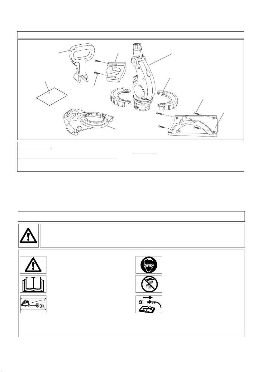
Carton Contents
IMPORTANT !
Please check the contents of the carton are correct BEFORE assembling your new product.
IF ANY P
ARTS ARE MISSING CONTACT:-
Husqvarna Outdoor Products Customer Service Department direct
Telephone : 01325 300303 Fax : 01325 318193
Safety
If not used properly this product can be dangerous! This product can cause serious injury to the operator and others, the warnings and safety instructions must be followed to ensure reasonable safety and
efficiency in using this product. The operator is responsible for following the warning and safety instructions in this manual and on the product.
Explanation of Symbols on your product
Warning
Read the user instructions carefully
to make sure you understand all
the controls and what they do.
Keep others, including children, pets
and bystanders outside the 10 metre
hazard zone. Stop the trimmer immediately if you are approached.
The use of eye protection is recommended to protect against objects
thrown by the nylon line.
To avoid the possibility of electric
shock, do not use in damp or wet
conditions.
Switch off! Remove plug from battery pack before adjusting, cleaning
or if cable is damaged.
Warning
The cutting line continues to rotate after the
machine has been switched off.
steady handle
guard
instruction
manual
wheel
trimmer
head
Trimmer Head
storage holder
screws x 4
steady handle
storage holder
screws x 2
10m
360º
Page 3
General
1. Never allow children or people unfamiliar with these
instructions to use the product. Local regulations may
restrict the age of the operator.
2. Only use the product in the manner and for the
functions described in these instructions.
3. Never operate the product when you are tired, ill or
under the influence of alcohol, drugs or medicine.
4. The operator or user is responsible for accidents
or hazards occurring to other people or their property.
5. Keep bystanders away. Do not operate whilst people,
especially children or pets are in the area.
Battery
Cordless Battery Powered Products require special
care.
1. AVOID ACCIDENTAL STARTING
KEEP HANDS AND FINGERS AWAY FROM THE
SWITCH LEVER WHILE CARRYING THE PRODUCT.
2. Do not attempt to repair the unit including the battery.
Nylon line replacement and cleaning the unit are the
only items suitable for user maintenance.
3. Do not insert any object into the motor area.
Keep free of debris to avoid overheating.
Preparation
1. While using your product always wear substantial
footwear and long trousers.
2. Before using the machine and after any impact,
check for signs of wear or damage and repair as
necessary.
3. Inspect the area to be cut before each use. Remove
all objects such as stones, broken glass, nails, wire,
string etc, which can be thrown or become entangled
in the trimmer head.
4. Check that the cutting head, spool and cap are
fitted correctly.
Use
1. Use the trimmer only in daylight or good artificial light.
2. Avoid operating your trimmer in wet grass, where feasi-
ble.
3. Take care in wet grass, you may lose your footing.
4. On slopes, be extra careful of your footing and
wear non-slip footwear.
5. Do not walk backwards when trimming, you
could trip. Walk, never run.
6. Switch off before pushing the trimmer over surfaces other than grass.
7. Never operate the trimmer with damaged guards
or without guards in place.
8. Never fit metal cutting elements.
9. Keep hands and feet away from the cutting means
at all times and especially when switching on the
motor.
10. Keep cutting head below waist level.
11. Do not lean over the trimmer guard whilst trimming or
edging - objects may be thrown by the cutting line.
12. Beware of cut-off pieces of nylon line ejected during
use.
13. If you hit an object, do not use your trimmer until
you are sure that the entire trimmer is in a safe
operating condition.
14. If the trimmer starts to vibrate abnormally, check
immediately. Excessive vibration can cause
injury.
Maintenance and storage
1. Keep all nuts, bolts and screws tight to be sure
the trimmer is in safe working condition.
2. Replace worn or damaged parts for safety.
3. Only use the replacement cutting line specified
for this product.
4. Only use replacement parts and accessories recommended by Husqvarna Outdoor Products.
5. To avoid the risk of injury keep fingers and hands
clear of the line cutter on the leading edge of the
guard.
6. Clean unit with a dry cloth. Never use metal
objects to clean the unit.
7. Inspect and maintain the trimmer regularly. Any
repairs must be carried out by an authorised repairer.
Assembly Instructions
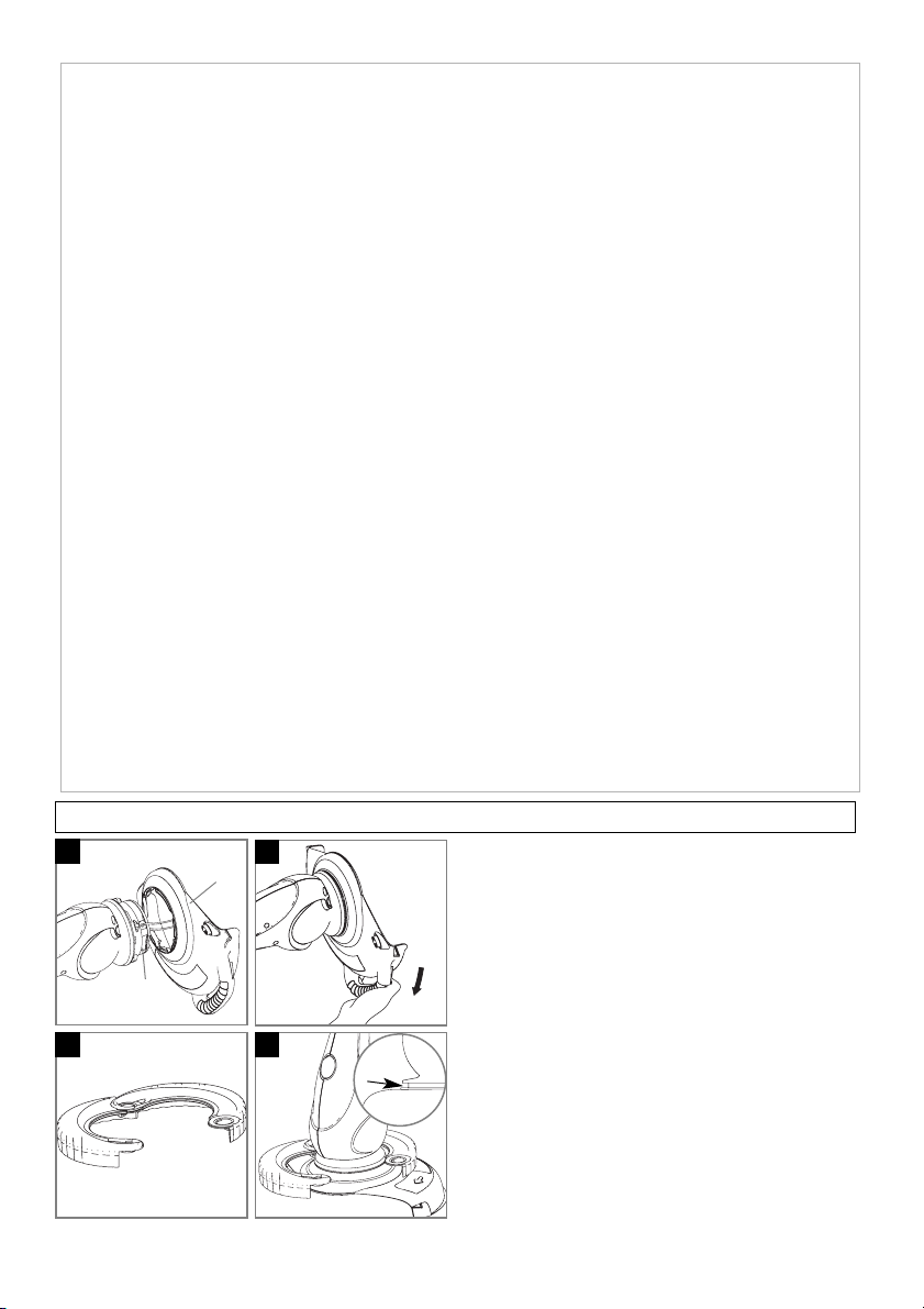
Safety Guard Assembly (A) & (B)
1. Locate the safety guard (B1) over the cutting head
(A2). Ensure the nylon line is fed through the hole
in the safety guard as illustrated in fig A.
2. Push into location and turn safety guard in the
direction illustrated in Fig B, until a click is
heard and the safety guard is securely locked
in position.
• ENSURE THE SAFETY GUARD IS SECURELY IN PLACE BY ATTEMPTING TO TWIST
GUARD.
Wheel Assembly (C) & (D)
1. Fix the 2 halves of the wheel together as illustrated in fig C.
2. Attach the wheel to the trimmer making sure that it
is located into the groove on the trimmer head (D1).
3. Clip the wheel together on the other side, making sure it is secure.
4. The wheel should turn freely.
B
A
C D
1
2
1
Page 4

Assembly Instructions con’t
Attatching the Trimmer Head to the Sabre Handle
1. Push the Trimmer Head onto the Sabre Handle until you hear a click. (E1)
2. Push the Trimmer Head further onto the Sabre Handle until it reaches the mark shown in Fig E2.
3. Turn the Trimmer Head collar until it is secure. (E3)
E2
E1
To adjust the Sabre handle length
1. Loosen the Sabre Handle collar. (G1)
2. Adjust length of the handle to the most comfortable
operating position (G2).
3. Re-tighten the Sabre Handle collar.
G2
G1
E3
Sabre Handle Length Adjustment
F1
F2
F3
Fitting the Steady Handle
1. Squeeze the lever on the steady handle (F1)
2. Attach the steady handle to product by releasing the lever and letting the handle latches fix into the slots on the
Sabre Handle.(F2)
3. Removal is the reverse procedure.
Adjusting the Steady Handle
1. Adjust the steady handle to a comfortable operating position by squeezing the lever and moving the handle up
and down the Sabre Handle (F3)
Page 5

Auto Line Feed System
H
line cutter
How the automatic line feed works (H)
1. When initially switching on the trimmer, a small length
of line is fed out.
2. A ‘clattering’ noise will be heard when the nylon line
hits the line cutter. DO NOT BE ALARMED this is
quite normal. After approximately 5 seconds the line
will be cut to the correct length and the noise will
reduce as the motor reaches full speed.
• Make sure the motor is up to full speed before
trimming or edging.
3. If the noise of the nylon line being cut cannot be
heard, more line will need to be fed out.
4. To feed more line, it is first necessary to to allow the
motor to stop completely, then re-start, allowing the
motor to reach full speed.
5. Repeat step 4. until you hear the line hitting against the
cutter. (Do not repeat this procedure more than 6 times)
6. If problems are experienced with the automatic line
feed refer to Fault Finding Chart.
Page 6

How to trim and edge
• WARNING
• The use of eye protection is recommended.
Do not lean over the trimmer whilst trimming or
edging, objects may be thrown by the cutting line.
Do not allow cutting head to rest on the ground.
Do not overload your trimmer.
Overloading can be avoided by making sure the
motor speed does not drop unduly.
• BEFORE USE
Make sure that the cutting line is fed out.
• Make sure motor is up to full speed before trimming or edging.
To start your Product
1. Attach your product to the fully charged Power
Pack.(J)
• The assembled product is provided with a lock-
off button (K1) to prevent accidental starting.
2. To start, press lock-off button (J1), squeeze the
switch lever (K2), release lock-off button.
How to trim
1. Cut with nylon line at an angle using the tip. (L).
2. Swing trimmer in and out of the cutting area taking
small cuts (M)
3. Line is fed out automatically every time the trimmer
head stops rotating and returns to operating speed.
• Extra line can be fed out manually as described in
Manual line feed
4. To stop your trimmer release the switch lever.
How to edge
1. To convert to edging mode, press button (N1) and
twist head (N2). An audible "click" will confirm that
the head is locked.
2.
To start, press lock-off button (K1), squeeze the
switch lever (K2), release lock-off button.
3. Rest product on wheel for extra stability and line up
the edge of the lawn with the two indicators on the
guard (P1). Edge in direction indicated in Fig P.
4. To stop your product release the switch lever.
5. To return to trimming mode, press button and twist
head back the opposite way. An audible "click" will
confirm that the head is locked.
How to use your product under shrubs & bushes
1. To enable your product to be used under shrubs and
bushes, press the lever at the back of the trimmer
head (Q)
2. Tilt the trimmer head to one of two positions (R)
3. To return to trimming mode, press the lever at the
back of the trimmer head (Q).
L
N
M
1
2
1
P
K
1
2
Q
R
J
Page 7

Cutting Head
To remove spool cap
1. Press and hold in the two cap release latches. (T).
2. Pull
cap away from the spoolholder. (T).
When r
efitting the spool cap
1. Keep all areas of the cap and spoolholder clean.
Failure to do so may prevent the cap being securely
located in the spoolholder.
2. Replace the cap, pr
essing firmly DOWN towards
the spoolholder to ensure cap is fully located.
3. Check that the cap is correctly fitted by trying to
remove it without depressing the two latches.
T
o r
eplace nylon line.
For your convenience it is recommended you buy spool
and line complete. Nylon line only is also available. Both
are available from Husqvarna Outdoor Products stockists.
T
o fit spool and line complete:
1. Remove old spool.
2. Place new spool into spoolholder with cut out ar
ea of
the spool in line with eyelet as shown in figure V.
3. Release line from cleat and feed line through eyelet (V).
• Ensure spool is fully located by gently rotating it during fitment, whilst keeping the spoolholder steady.
4. Refit the cap.
T
o fit nylon line only:
• Remember! Your product is designed to use only
nylon line with a maximum diameter of 1.5mm
.
Use only genuine Flymo nylon line.
1. Take approximately 10 metres of line. Insert 15mm of
line into the hole in the spool (W) and wind line in the
direction of the arrows on the top of the spool. Leave
approximately 100mm of line unwound and place into
cleat as illustrated in figure W1.
2. Care should be taken to ensure that the line is neatly
coiled on the spool. Failure to do so will impair the
efficiency of the automatic line feed.
3. Then fit spool as described in ‘To fit spool and line
complete’, section above.
Cap
Cap release
latch
Spool
Spoolholder
Eyelet
T
V
W
Cleat
Cut out area
of spool
Eyelet
W1
Manual line feed
S
manual line
feed button
To manually feed the nylon line (S)
1. If required line can be fed out manually.
2. To operate, press and release manual line feed but-
ton, whilst gently pulling on the line until it reaches the
line cutter.
3. If the line extends past the line cutter, too much line
has been fed out.
4. If too much line is fed out, remove the spool cap and
click spool anti-clockwise until the line is at the desired
length.
Page 8

Maintenance
X2
X1
• WARNING
Cutting head continues to rotate after the trimmer has been switched off. Keep fingers and
hands clear of the line cutter on leading edge of
guard.
Caring for your product
After you have finished using your product follow the procedure below:
1. Never clean your trimmer with water, cleaning fluids,
or solvents, just remove debris with a suitable tool, a
soft brush or dry cloth.
2. Using a soft brush, clean around the inside of the
safety guard, the cutting head (X1) and the motor
housing air vents. (X2)
3. Remove the wheel by pressing one of the buttons.
Clean the wheel and groove on trimmer head with a
soft brush (X3 & X4).
4. Attach wheel as described in Wheel Assembly.
5. Inspect the product carefully, especially the parts of
the cutting head.
6. If your product is damaged in any way contact your
local Husqvarna Outdoor Products approved service
centre.
• Never use a damaged product.
Storing your product
1. Attach the Steady Handle Storage Holder to the wall
with the two screws provided (Y1)
2. Store the Steady Handle in the holder as illustrated in
Fig Y2
3. Attach the Trimmer Head Storage Holder to the wall
with the two screws provided (Z1)
4. Store the Trimmer Head in the holder as illustrated in
Fig Z2
• Store in a cool, dry place and out of reach of children.
X4
X3
Y1
Z1
Y2
Z2
Page 9

Fault Finding Chart
FAULT CHECK ACTION
Is the automatic line feed working?
Manually feed out line.
SEE “MANUAL LINE FEED”
Is the line fed out and visible?
Has line been removed from
cleat?
Remove cap and spool, free line
and re-fit spool and cap. SEE
“CUTTING HEAD”
The line may be jammed on the
spool. Rewind line to remove
crossed loops. Check that line is
in correct section of spool.
Is the manual line feed working?
Has too much line been fed out?
SEE “MANUAL LINE FEED”
Contact your local approved Service
Centre or Husqvarna Outdoor
Products Customer Service.
Is the line cutter missing from
the safety guard?
Contact Husqvarna Outdoor Products Customer Service
Telephone : 01325 302302
No
No
No
Yes
Yes
LINE NOT FEEDING
OR
LINE TOO SHORT
OR
TRIMMER VIBRATES
CONTINUOUS CLATTER-
ING NOISE
LINE SNAPS CONTINU-
OUSLY
IF NONE OF THE ABOVE
OR IF FAULT PERSISTS
Has the motor reached full
speed before use?
No
Allow the motor to reach full speed
before use.
Are you using the trimmer correctly?
?
Only use tip of nylon line to trim.
SEE “How to trim and edge”
Is the line jamming on the
spool?
Yes
Rewind the line on the spool, if
symptoms still persist, change
spool and line.
Clean wheel and groove on trimmer head. SEE “MAINTENANCE”
WHEEL STOPS TURNING
Environmental Information
1. We strongly recommend that your product is serviced at least every
twelve months, more often in a professional application.
2. Always use genuine Flymo Spare Parts.
3. Prepacked spares are available from most Husqvarna
Outdoor Products stockists.
4. Your product is uniquely identified by a silver and black product rating label.
5. If you have a problem with your machine contact your local Approved
Service Centre ensuring you have full details of your product as
described on the product rating label.
6. Should it be necessary for work to be carried out by your Service
Centre, it is important to take your complete machine including
cable and any extension cables used.
A network of specialist dealers can be found in your local Yellow Pages.
To obtain service on your Flymo product simply telephone or visit your
local Service Centre. Should you require service under the terms of our
guarantee the Service Centre will require proof of purchase.
All of the centres listed stock genuine Flymo Spare Parts.
NOTE: Our Service Repairers act on their own behalf and are
not empowered to commit or legally bind Husqvarna
Outdoor Products in any manner whatsoever.
Service Recommendations
Husqvarna Outdoor Products are manufactured under an
Environmental Management System (ISO 14001) using, where
practical, components manufactured in the most environmentally
responsible manner, according to company procedures, and with
the potential for recycling at the end of the products’ life.
• Packaging is recyclable and plastic components have been labelled
(where practical) for categorised recycling.
• Awareness of the environment must be considered when dispos-
ing of ‘end-of-life’ product.
• If necessary, contact your local authority for disposal information.
The symbol on the product or on its packaging indicates that
this product may not be treated as household waste. Instead it
shall be handed over to the applicable collection point for the recycling of electrical and electronic equipment. By ensuring this product is disposed of correctly, you will help prevent potential negative
consequences for the environment and human health, which could
otherwise be caused by inappropriate waste handling of this product.
For more detailed information about recycling of this product, please contact your local council office, your household waste disposal service or the
shop where you purchased the product.
Page 10

5107422-01
Husqvarna Outdoor Products
Aycliffe Industrial Park
NEWTON AYCLIFFE
Co.Durham DL5 6UP
ENGLAND
Telephone - (00) 44 1325 300303 Fax - (00) 44 1325 310339
UK Customer Helpline - 01325 300303 Fax - 01325 310339
Our policy of continuous improvement means that the specification of products may be altered from time to time without prior notice.
If any part is found to be defective due to faulty manufacture
within the guarantee period, Husqvarna Outdoor Products,
through its Authorised Service Repairers will effect the repair or
replacement to the customer free of charge providing:
(a) The fault is reported directly to the Authorised Repairer.
(b) Proof of purchase is provided.
(c) The fault is not caused by misuse, neglect or faulty adjust-
ment by the user.
(d) The failure has not occurred through fair wear and tear.
(e) The machine has not been serviced or repaired, taken apart
or tampered with by any person not authorised by
Husqvarna Outdoor Products.
(f) The machine has not been used for hire.
(g) The machine is owned by the original purchaser.
(h) The machine has not been used outside of the country for
which it was specified.
(i) The machine has not been used commercially.
* This guarantee is additional to, and in no way diminishes
the customers statutory rights.
Failures due to the following are not covered, therefore it is important that
you read the instructions contained in this Operator's Manual and understand how to operate and maintain your machine:
Failures not covered by guarantee
* Replacing Nylon Line.
* Failures as a result of not reporting an initial fault.
* Failures as a result of sudden impact.
* Failures as a result of not using the product in accordance
with the instructions and recommendations contained in this
Operator's Manual.
* Machines used for hire are not covered by this guarantee.
* The following items listed are considered as wearing parts and their life
is dependent on regular maintenance and are, therefore not normally
subject to a valid warranty claim: Nylon Line., Spool & Line
* Caution!
Husqvarna Outdoor Products does not accept liability under the
warranty for defects caused in whole or part, directly or indirectly
by the fitting of replacement parts or additional parts that are not
either manufactured or approved by Husqvarna Outdoor
Products, or by the machine having been modified in any way.
I, the undersigned M. Bowden of Husqvarna
Outdoor Products, Aycliffe Industrial Park, NEW-
TON AYCLIFFE, Co. Durham. DL5 6UP. Certify
that the Product:-
Category........ Battery Lawn Trimmer
Make.............. Husqvarna Outdoor
Products
Conforms to the specifications of Directive 2000/14/EEC
I, the undersigned M. Bowden of Husqvarna
Outdoor Products, Aycliffe Industrial Park, NEW-
TON AYCLIFFE, Co. Durham. DL5 6UP Certify
that a sample of the above product has been
tested using directive 81/1051/EEC as a guide.
The maximum A-weighted sound pressure level
recorded at operator position under free field semi
anechoic chamber conditions was :-
I, the undersigned M. Bowden of Husqvarna
Outdoor Products, Aycliffe Industrial Park,
NEWTON AYCLIFFE, Co. Durham. DL5 6UP
Certify that a sample of the above product has
been tested using ISO 5349 as a guide. The
maximum weighted root mean square value of
vibration recorded at operator’s hand position
was:-
Type of Cutting Device.... Cutting Line
Identification of Series...... See Product Rating Label
Conformity Assesment Procedure....ANNEX VI
Notified Body.................... Intertek., Cleeve Road, Leatherhead,
Surrey. KT22 7SB England
Other Directives:-............. 98/37/EEC, 89/336/EEC
& applicable standards:- EN786, EN60335-1, EN60335-2-29, EN55022,
EN61000-4-2, EN61000-4-3, EN55014-1, EN61000-3-2, EN61000-3-3,
Type ................................................................. GTC24A
Width of Cut ..................................................... 25 cm
Speed of Rotation of Cutting Device ............... 10,000 RPM
Guaranteed sound power level ....................... 93 dB(A)
Measured Sound Power Level ........................ 92 dB(A)
Level ................................................................ 75.6 dB(A)
Value ................................................................ 1.87 m/s
2
Weight ............................................................. 6.89 kg
EC Declaration of Conformity
Newton Aycliffe, 14/05/2005
M. Bowden,
Research & Development Director
Guarantee & Guarantee Policy
 Loading...