

Page 1

VT Plus HF
Gas Flow Analyzer
Operators Manual
PN 2137275
May 2008, Rev. 2, 4/09
© 2008, 2009 Fluke Corporation, All rights reserved. Printed in USA. Specifications are subject to change without notice.
All product names are trademarks of their respective companies.
Page 2

Warranty and Product Support
Fluke Biomedical warrants this instrument against defects in materials and workmanship
for one year from the date of original purchase. During the warranty period, we will
repair or at our option replace, at no charge, a product that proves to be defective,
provided you return the product, shipping prepaid, to Fluke Biomedical. This warranty
covers the original purchaser only and is not transferable. The warranty does not apply if
the product has been damaged by accident or misuse or has been serviced or modified by
anyone other than an authorized Fluke Biomedical service facility. NO OTHER
WARRANTIES, SUCH AS FITNESS FOR A PARTICULAR PURPOSE, ARE
EXPRESSED OR IMPLIED. FLUKE SHALL NOT BE LIABLE FOR ANY SPECIAL,
INDIRECT, INCIDENTAL OR CONSEQUENTIAL DAMAGES OR LOSSES,
INCLUDING LOSS OF DATA, ARISING FROM ANY CAUSE OR THEORY.
This warranty covers only serialized products and their accessory items that bear a
distinct serial number tag. Recalibration of instruments is not covered under the warranty
This warranty gives you specific legal rights and you may also have other rights that vary
in different jurisdictions. Since some jurisdictions do not allow the exclusion or limitation
of an implied warranty or of incidental or consequential damages, this limitation of
liability may not apply to you. If any provision of this warranty is held invalid or
unenforceable by a court or other decision-maker of competent jurisdiction, such holding
will not affect the validity or enforceability of any other provision.
07/07
Page 3

Notices
All Rights Reserved
© Copyright 2008, Fluke Biomedical. No part of this publication may be reproduced, transmitted, transcribed, stored in a retrieval
system, or translated into any language without the written permission of Fluke Biomedical.
Copyright Release
Fluke Biomedical agrees to a limited copyright release that allows you to reproduce manuals and other printed materials for use in
service training programs and other technical publications. If you would like other reproductions or distributions, submit a written
request to Fluke Biomedical.
Unpacking and Inspection
Follow standard receiving practices upon receipt of the instrument. Check the shipping carton for damage. If damage is found, stop
unpacking the instrument. Notify the carrier and ask for an agent to be present while the instrument is unpacked. There are no special
unpacking instructions, but be careful not to damage the instrument when unpacking it. Inspect the instrument for physical damage such
as bent or broken parts, dents, or scratches.
Technical Support
For application support or answers to technical questions, either email techservices@flukebiomedical.com or call 1-800- 850-4608 ext
2560 or 1-440-498-2560.
Claims
Our routine method of shipment is via common carrier, FOB origin. Upon delivery, if physical damage is found, retain all packing
materials in their original condition and contact the carrier immediately to file a claim. If the instrument is delivered in good physical
condition but does not operate within specifications, or if there are any other problems not caused by shipping damage, please contact
Fluke Biomedical or your local sales representative.
Standard Terms and Conditions
Refunds and Credits
Please note that only serialized products and their accessory items (i.e., products and items bearing a distinct serial number
tag) are eligible for partial refund and/or credit. Nonserialized parts and accessory items (e.g., cables, carrying cases,
auxiliary modules, etc.) are not eligible for return or refund. Only products returned within 90 days from the date of original
purchase are eligible for refund/credit. In order to receive a partial refund/credit of a product purchase price on a serialized product, the
product must not have been damaged by the customer or by the carrier chosen by the customer to return the goods, and the product
must be returned complete (meaning with all manuals, cables, accessories, etc.) and in “as new” and resalable condition. Products not
returned within 90 days of purchase, or products which are not in “as new” and resalable condition, are not eligible for credit return and
will be returned to the customer. The Return Procedure (see below) must be followed to assure prompt refund/credit.
Restocking Charges
Products returned within 30 days of original purchase are subject to a minimum restocking fee of 15 %. Products returned in excess of
30 days after purchase, but prior to 90 days, are subject to a minimum restocking fee of 20 %. Additional charges for damage and/or
missing parts and accessories will be applied to all returns.
Return Procedure
All items being returned (including all warranty-claim shipments) must be sent freight-prepaid to our factory location. When you return
an instrument to Fluke Biomedical, we recommend using United Parcel Service, Federal Express, or Air Parcel Post. We also
recommend that you insure your shipment for its actual replacement cost. Fluke Biomedical will not be responsible for lost shipments
or instruments that are received in damaged condition due to improper packaging or handling.
Use the original carton and packaging material for shipment. If they are not available, we recommend the following guide for
repackaging:
Use a double-walled carton of sufficient strength for the weight being shipped.
Use heavy paper or cardboard to protect all instrument surfaces. Use nonabrasive material around all projecting parts.
Use at least four inches of tightly packed, industry-approved, shock-absorbent material around the instrument.
Returns for partial refund/credit:
Every product returned for refund/credit must be accompanied by a Return Material Authorization (RMA) number, obtained from our
Order Entry Group at 1-800- 850-4608 ext 2560 or 1-440-498-2560.
Page 4

Repair and calibration:
To find the nearest service center, go to www.flukebiomedical.com/service
In the U.S.A.:
Cleveland Calibration Lab
Tel: 1-800-850-4606
Email: globalcal@flukebiomedical.com
Everett Calibration Lab
Tel: 1-888-993-5853
Email: service.status@fluke.com
In Europe, Middle East, and Africa:
Eindhoven Calibration Lab
Tel: +31-402-675300
Email: ServiceDesk@fluke.com
In Asia:
Everett Calibration Lab
Tel: +425-446-6945
Email: mailto:service.international@fluke.com
, or
Certification
This instrument was thoroughly tested and inspected. It was found to meet Fluke Biomedical’s manufacturing specifications when it
was shipped from the factory. Calibration measurements are traceable to the National Institute of Standards and Technology (NIST).
Devices for which there are no NIST calibration standards are measured against in-house performance standards using accepted test
procedures.
WARNING
Unauthorized user modifications or application beyond the published specifications may result in electrical shock hazards or
improper operation. Fluke Biomedical will not be responsible for any injuries sustained due to unauthorized equipment
modifications.
Restrictions and Liabilities
Information in this document is subject to change and does not represent a commitment by Fluke Biomedical. Changes made
to the information in this document will be incorporated in new editions of the publication. No responsibility is assumed by
Fluke Biomedical for the use or reliability of software or equipment that is not supplied by Fluke Biomedical, or by its
affiliated dealers.
Manufacturing Location
The VT PLUS HF Gas Flow Analyzer is manufactured in Everett, Washington by Fluke Biomedical, 6920 Seaway Blvd.,
Everett, WA, U.S
Page 5

Table of Contents
Chapter Title Page
1 Introduction and Specifications......................................................... 1-1
Introduction........................................................................................................ 1-3
Key Features ...................................................................................................... 1-3
Unpacking and Inspection.................................................................................. 1-3
General Safety Considerations........................................................................... 1-4
Symbols ......................................................................................................... 1-4
Warnings and Cautions.................................................................................. 1-4
Instrument Familiarity ....................................................................................... 1-5
Front Panel..................................................................................................... 1-6
Right Panel .................................................................................................... 1-6
Rear Panel...................................................................................................... 1-7
Left Panel....................................................................................................... 1-7
Front Panel Details ........................................................................................ 1-8
Specifications..................................................................................................... 1-10
General Specifications................................................................................... 1-10
Performance Specifications ........................................................................... 1-11
Breath Parameter Accuracy Specifications ................................................... 1-12
Accessories ........................................................................................................ 1-14
2 Connection and Setup ........................................................................ 2-1
Connecting the Analyzer ................................................................................... 2-3
Pneumatic Connections ................................................................................. 2-3
High Flow (Inlet and Exhaust).................................................................. 2-3
Low Flow (Inlet and Exhaust)................................................................... 2-3
High Pressure (+ and -) ............................................................................. 2-3
Low Pressure (+ and -).............................................................................. 2-4
Test System Setup ......................................................................................... 2-4
Bi-directional Flow Mode ......................................................................... 2-4
Unidirectional Flow Mode ........................................................................ 2-5
Printer Cable Attachment .............................................................................. 2-6
Using the Setup Screen ...................................................................................... 2-7
Setting Testing Parameters ................................................................................ 2-7
Gas Settings................................................................................................... 2-8
Gas Type ................................................................................................... 2-8
i
Page 6

VT Plus HF
Operators Manual
Gas Temperature ....................................................................................... 2-9
Ambient Temperature ............................................................................... 2-9
Relative Humidity ..................................................................................... 2-9
Correction Mode............................................................................................ 2-10
Barometric Pressure....................................................................................... 2-10
Breath Detection............................................................................................ 2-11
Inspiratory/Expiratory Tidal Volumes........................................................... 2-12
Zero Mode ..................................................................................................... 2-12
Setting Analyzer Operating Parameters............................................................. 2-13
Time............................................................................................................... 2-13
Date ............................................................................................................... 2-14
Date Format ................................................................................................... 2-14
Demo Data..................................................................................................... 2-14
Filtering ......................................................................................................... 2-15
Display Calibration Date on Startup Screen.................................................. 2-15
Serial Mode ................................................................................................... 2-15
Printer Options............................................................................................... 2-16
Printer Type............................................................................................... 2-16
Graphics .................................................................................................... 2-17
Audio Levels ................................................................................................. 2-17
General ...................................................................................................... 2-17
Keypad ...................................................................................................... 2-17
Errors......................................................................................................... 2-18
Restore Defaults ............................................................................................ 2-18
Utilities .............................................................................................................. 2-20
Oxygen Sensor Calibration............................................................................ 2-20
System Diagnostics ....................................................................................... 2-21
Linearization.................................................................................................. 2-21
Unlock Calibration ........................................................................................ 2-22
Information ........................................................................................................ 2-22
3 Operation ............................................................................................. 3-1
Measured Signals............................................................................................... 3-3
High Flow...................................................................................................... 3-3
Low Flow ...................................................................................................... 3-3
Airway Pressure............................................................................................. 3-3
Low Pressure ................................................................................................. 3-3
Barometric Pressure....................................................................................... 3-4
High-Pressure Measurement.......................................................................... 3-4
Oxygen Concentration................................................................................... 3-4
Calculated Breath Parameters........................................................................ 3-4
Screen Objects ................................................................................................... 3-6
Title Bar......................................................................................................... 3-7
Data Plots ...................................................................................................... 3-7
Breath Parameters.......................................................................................... 3-7
Breath Detection Icons .................................................................................. 3-8
Instantaneous Numeric Data.......................................................................... 3-9
Statistics......................................................................................................... 3-9
Selecting Breath Parameters .............................................................................. 3-10
Flow Screens...................................................................................................... 3-11
High-Flow Screen.......................................................................................... 3-11
Low-Flow Screen .......................................................................................... 3-12
Pressure Screens ................................................................................................ 3-13
High-Pressure Screen .................................................................................... 3-13
ii
Page 7

Contents (continued)
Low Pressure Screen ..................................................................................... 3-14
Airway Pressure Screen................................................................................. 3-15
Volume Screen................................................................................................... 3-16
Oxygen Screen................................................................................................... 3-17
Full Breath Parameters Test Screen................................................................... 3-18
Monitor Screen .................................................................................................. 3-19
Units of Measure................................................................................................ 3-20
Special Functions............................................................................................... 3-21
Trend Test...................................................................................................... 3-21
Leak Test ....................................................................................................... 3-24
Stacked Volume Test..................................................................................... 3-27
RT200 Emulation Mode ................................................................................ 3-28
Assist Test ..................................................................................................... 3-31
High Frequency Oscillator Mode .................................................................. 3-32
4 Remote Operation ............................................................................... 4-1
Getting Started ................................................................................................... 4-3
System Requirements .................................................................................... 4-3
Connecting to the Analyzer ........................................................................... 4-3
Installing the Software................................................................................... 4-3
Starting the Software ..................................................................................... 4-4
Overview of VT for Windows PC Software...................................................... 4-5
Menu Bar ........................................................................................................... 4-6
Toolbar............................................................................................................... 4-8
Main Screens and Tests ..................................................................................... 4-9
Monitor Screen .............................................................................................. 4-9
Single Plot Screen.......................................................................................... 4-10
Loop Screen................................................................................................... 4-11
Full Test Screen............................................................................................. 4-12
Trend Test...................................................................................................... 4-12
Leak-Test....................................................................................................... 4-16
Stacked Volume Test Screen......................................................................... 4-18
Serial Communications...................................................................................... 4-20
Selecting COM Port ...................................................................................... 4-20
Selecting the Serial Communications Mode ................................................. 4-20
Data and File Handling ...................................................................................... 4-21
Events ............................................................................................................ 4-21
Opening and Closing Data Files.................................................................... 4-22
File Control Interface .................................................................................... 4-23
Playback Controls ..................................................................................... 4-24
Event Markers ........................................................................................... 4-25
File Information Panel............................................................................... 4-26
Event Panel ............................................................................................... 4-26
Generating Signal (.sig) Files ........................................................................ 4-26
Generating Parameter (.par) Files.................................................................. 4-26
Report Printing................................................................................................... 4-27
Operating System Loading ................................................................................ 4-27
Plots ................................................................................................................... 4-28
Automatically Re-scaling Plots ..................................................................... 4-28
Manually Re-scaling Plots............................................................................. 4-28
Signal Selection ............................................................................................. 4-29
Zeroing............................................................................................................... 4-30
Manual Zeroing ............................................................................................. 4-30
Automatic Zeroing......................................................................................... 4-30
iii
Page 8

VT Plus HF
Operators Manual
Other Setup Functions ....................................................................................... 4-31
Breath Detect ................................................................................................. 4-31
Breath Detect Threshold................................................................................ 4-31
Gas Settings................................................................................................... 4-31
Barometric Pressure....................................................................................... 4-34
5 Maintenance, Service, and Calibration.............................................. 5-1
Maintenance....................................................................................................... 5-3
Avoiding Damage.......................................................................................... 5-3
Cleaning......................................................................................................... 5-3
Oxygen Sensor Replacement ............................................................................. 5-3
Fuse Replacement .............................................................................................. 5-4
Service and Calibration...................................................................................... 5-5
Appendices
A Gas Analyzer Tutorial ................................................................................. A-1
B Error Messages............................................................................................ B-1
C Troubleshooting .......................................................................................... C-1
iv
Page 9

List of Tables
Table Title Page
1-1. Symbols.................................................................................................................. 1-4
1-2. Front Panel Components ........................................................................................ 1-6
1-3. Right Panel Components........................................................................................ 1-6
1-4. Back Panel Components ........................................................................................ 1-7
1-5. Left Panel Components .......................................................................................... 1-7
1-6. Front Panel Functions ............................................................................................ 1-8
1-7. Breath Parameter Accuracy Specifications ............................................................ 1-13
1-8. Standard Accessories ............................................................................................. 1-14
1-9. Optional Accessories.............................................................................................. 1-15
2-1. Gas Type Values .................................................................................................... 2-8
2-2. Breath Detection Options....................................................................................... 2-11
2-3. Serial Port Options ................................................................................................. 2-15
2-4. Factory Defaults ..................................................................................................... 2-18
3-1. Parameters Calculated by the Analyzer ................................................................. 3-5
3-2. Display Components .............................................................................................. 3-6
3-3. Breath Detection Icons........................................................................................... 3-8
3-4. Available Units of Measure.................................................................................... 3-20
3-5. Available Conversion Factors ................................................................................ 3-21
3-6. Supported RT200 Functions................................................................................... 3-29
4-1. Elements of the VT for Windows Interface ........................................................... 4-6
4-2. Menu Bar Options .................................................................................................. 4-7
4-3. Setup Submenu Options......................................................................................... 4-7
4-4. Toolbar Buttons...................................................................................................... 4-8
4-5. Data Types ............................................................................................................. 4-21
4-6. Generated File Types ............................................................................................. 4-21
4-7. Playback Controls .................................................................................................. 4-24
B-1. Error Messages....................................................................................................... B-1
C-1. Troubleshooting ..................................................................................................... C-1
v
Page 10

VT Plus HF
Operators Manual
vi
Page 11

List of Figures
Figure Title Page
1-1. Front and Right Analyzer Panels ........................................................................... 1-5
1-2. Rear and Left Analyzer Panels............................................................................... 1-7
1-3. Analyzer Front Panel.............................................................................................. 1-8
2-1. Connecting the Analyzer in a Bi-Directional Flow Mode ..................................... 2-4
2-2. Connecting the Analyzer to the Inspiratory Limb of the Breathing Circuit........... 2-5
2-3. Connecting the Analyzer to the Expiratory Limb of the Breathing Circuit ........... 2-5
3-1. Information Shown on Analyzer Display............................................................... 3-6
3-2. The Assist Test....................................................................................................... 3-31
3-3. Ventilator Breathing Circuit Setup for Bi-Directional Measurements................... 3-31
4-1. VT for Windows PC software Interface................................................................. 4-5
4-2. VT for Windows Menu Bar ................................................................................... 4-6
4-3. VT for Windows Toolbar....................................................................................... 4-8
4-4. Monitor Screen....................................................................................................... 4-9
4-5. Single Plot Screen .................................................................................................. 4-10
4-6. Loop Screen ........................................................................................................... 4-11
4-7. Full Test Screen...................................................................................................... 4-12
4-8. Trend Test: Setup Screen ....................................................................................... 4-13
4-9. Trend Test Screen: Testing Underway................................................................... 4-14
4-10. Trend Test Screen: Final Values Displayed ........................................................... 4-15
4-11. Leak Test: Setup Screen......................................................................................... 4-16
4-12. Leak Test Screen: Testing Underway .................................................................... 4-17
4-13. Stacked Volume Test: Setup Screen ...................................................................... 4-18
4-14. Stacked Volume Screen: Testing Underway.......................................................... 4-19
4-15. File Menu ............................................................................................................... 4-22
4-16. File Control Interface ............................................................................................. 4-23
4-17. File Information Panel............................................................................................ 4-26
5-1. Fuse Compartment ................................................................................................. 5-4
A-1. Circuit Connection for the Analyzer in Bi-directional Mode................................. A-6
vii
Page 12

VT Plus HF
Operators Manual
viii
Page 13

Chapter 1
Introduction and Specifications
Title Page
Introduction........................................................................................................ 1-3
Key Features ...................................................................................................... 1-3
Unpacking and Inspection.................................................................................. 1-3
General Safety Considerations........................................................................... 1-4
Symbols ......................................................................................................... 1-4
Warnings and Cautions.................................................................................. 1-4
Instrument Familiarity ....................................................................................... 1-5
Front Panel..................................................................................................... 1-6
Right Panel .................................................................................................... 1-6
Rear Panel...................................................................................................... 1-7
Left Panel....................................................................................................... 1-7
Front Panel Details ........................................................................................ 1-8
Specifications..................................................................................................... 1-10
General Specifications................................................................................... 1-10
Performance Specifications ........................................................................... 1-11
Breath Parameter Accuracy Specifications ................................................... 1-12
Accessories ........................................................................................................ 1-14
1-1
Page 14

VT Plus HF
Operators Manual
1-2
Page 15

Introduction and Specifications
Introduction 1
Introduction
The VT Plus HF Gas Flow Analyzer, referred to hereafter as the Analyzer, is a generalpurpose, gas flow analyzer with special modes for testing mechanical patient ventilators.
The Analyzer measures bidirectional flow in both high and low ranges, as well as highand low-pressure ranges. Users control the unit using the command system or a special
control mode that uses RT200-style commands. Multiple special-function tests allow
efficient troubleshooting.
The Analyzer can measure either high- or low-flow and pressure, eliminating the need for
gauges and flow meters. It measures 21 ventilator parameters and can display all of them
on one screen. Results can be printed directly from the unit or from Windows-compatible
software on a PC. The Analyzer also has onboard graphing capability and shows the
minimum, maximum, average, and absolute measurement for all parameters.
This manual provides a description of the Analyzer and its applications. It should be used
as a guide when using the instrument to analyze a ventilator and test lung.
Key Features
• Bi-directional flow, low- and high-pressure, volume, and oxygen concentration, and
pressure measurements
• Very high-frequency measurement capability – up to 900 BPM (15 Hz)
• RS232 and printer ports
• Included Windows-compatible graphics software
• Minimum, maximum, average, absolute, and graph for all parameters
• All 21ventilator parameters displayed on one screen simultaneously
• Operation by user-friendly command mode or RT200 command mode
• Operation with a variety of precision test lungs available from Fluke Biomedical to
complete a fully NIST-traceable ventilator test
• Tests the leak rate of a sealed vessel or test lung
• Tests whether a predetermined parameter deviates from limits set by the user
• Useful for pre-purchase evaluations of ventilators, incoming and routine performance
verification, troubleshooting clinical problems, and teaching principles of mechanical
ventilation
Unpacking and Inspection
Use the following checklist when unpacking the Analyzer. There are no special
unpacking instructions, but be careful not to damage the instrument when unpacking it.
• Inspect the shipping carton for damage. If the shipping carton is damaged, carefully
continue unpacking the instrument and note any dents and scratches on the Analyzer.
Save the damaged shipping carton and packing material for the carrier’s inspection.
• If there is no shipping damage, continue removing the Analyzer from the shipping
case. Save the box and packing materials.
Note
This box contains specifically designed inserts to ensure safe shipment of
the Analyzer. Please save these for return of the unit for service or
calibration.
1-3
Page 16

VT Plus HF
Operators Manual
General Safety Considerations
Symbols
• Perform a visual inspection to ensure that the Analyzer is intact and if there is any
physical damage, such as bent or broken parts, dents, or scratches. If the Analyzer
has been damaged, call the Fluke Biomedical Service Center immediately. If the
Analyzer be returned to Fluke for service, follow the procedure given under
Maintenance, Service, and Calibration: Packing Instructions.
• After unpacking the Analyzer, check to see if all of the standard accessories listed
under Accessories have been included with the Analyzer. If anything is missing,
contact the Fluke Biomedical Service Center.
Read the Users Manual before operating the Analyzer.
Table 1-1 describes the symbols associated with the Analyzer.
Table 1-1. Symbols
Symbol Description
X Hazardous voltage
W Important information; refer to manual
ΠConforms to UL Std 3101-1; certified to Can/USA Std C22.2 No. 1010.1
P Conforms to European Union directives
~
Do not dispose of this product as unsorted municipal waste. Go to Fluke’s
website for recycling information.
Hg Contains mercury. Dispose properly.
Warnings and Cautions
A Warning identifies hazardous conditions and actions that could cause bodily harm or
death.
A Caution identifies conditions and actions that could damage the Analyzer, the
equipment under test, or cause permanent loss of data.
To avoid possible electrical shock or personal injury, follow
these guidelines:
• Use this Analyzer only in the manner specified by the
manufacturer.
• Do not use the product if it operates abnormally.
XW Warning
1-4
• Plug the main power cord only into a power outlet that has a
protective earth contact to connect the chassis of the Analyzer to
ground.
• Do not use extension cords without earth ground, or a hazardous
condition may result.
• Turn off the Analyzer and disconnect its power cord before
opening the case or performing any service procedures.
Page 17
Introduction and Specifications
Instrument Familiarity 1
W Caution
To avoid damage to the Analyzer or adverse affects on its
performance, follow these guidelines:
• Do not expose the system to temperature extremes.
Ambient temperatures should remain between 10 °C and
40 °C. System performance may be adversely affected if
temperatures fluctuate above or below this range.
• Clean the Analyzer only by wiping it down with a clean, lint-
free cloth dampened with a mild detergent solution. A
solution of 70 % isopropyl alcohol may be used to remove
stains and clean the system. No other solvents are
recommended. Do not spray liquid directly on or immerse
the unit.
Instrument Familiarity
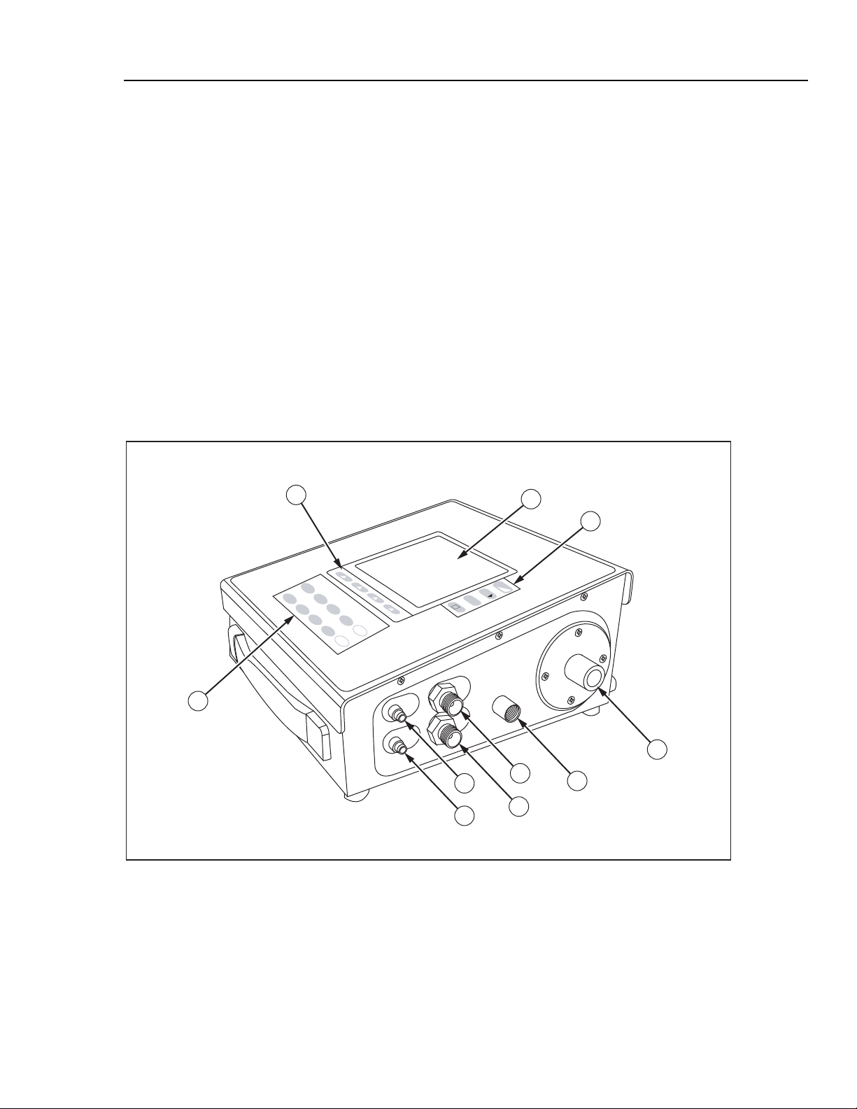
Figure 1-1 shows the top and right panels of the Analyzer.
3
1
2
F
L
O
W
0
P
R
F
U
E
L
S
L
S
U
TEST M
R
E
5
1
M
V
O
6
4
ODES
O
N
L
IT
U
O
M
R
E
2
Z
E
O
RO
2
7
3
M
S
O
E
R
T
E
U
P
4
8
P
A
R
A
M
E
T
E
9
R
S
+
gas or
d
flui
-
dry gas
only
ssure
±67kPa)
low pre
g (
range ±500mmH
II /
?
high flow &
inlet
gen
oxy
ge ± 300 lpm
ran
d.
gasses only
bele
dry
use
ual for
ept where la
s
ation
c
cifi
pe
W
exc
+
or
refer to users man
gas
complete inlet s
uid
fl
gas
dry
only
low flow
10
5
6
7
8
9
fec120.eps
Figure 1-1. Front and Right Analyzer Panels
1-5
Page 18

VT Plus HF
Operators Manual
Front Panel
Right Panel
The components of the front panel are listed in Table 1-2. See Front Panel Details for
detailed descriptions of front panel components.
Table 1-2. Front Panel Components
Label Description
A LCD Display with CFL backlight
B Contrast, Pause/resume, print, and help keys
C Soft keys
D Test Mode keys
The components of the right panel of the Analyzer are described in Table 1-3.
Table 1-3. Right Panel Components
Label Description
E Low Pressure (+) Gas Or Fluid Port
F Low Pressure (-) Dry Gas Only Port
G High Pressure (+) Gas Or Fluid Port
H High Pressure (-) Dry Gas Only Port
I Low Flow Inlet
J High Flow And Oxygen Inlet
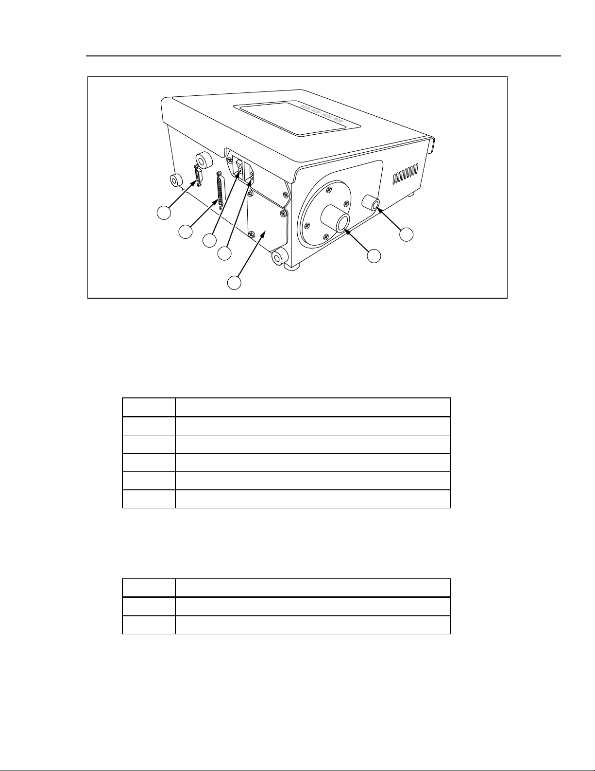
Figure 1-2 shows the rear and left panels of the Analyzer.
1-6
Page 19
Introduction and Specifications
1
Instrument Familiarity 1
Rear Panel
The components of the back panel are listed in Table 1-4.
Label Description
2
3
4
5
Figure 1-2. Rear and Left Analyzer Panels
Table 1-4. Back Panel Components
A RS232 Serial Port
B Parallel Printer Port
C Power Switch
D Power Cord Input
E Oxygen Sensor Access
7
6
fec121.eps
Left Panel
The components of the left panel are listed in Table 1-5.
Table 1-5. Left Panel Components
Label Description
F High-Flow Exhaust Port
G Low-Flow Exhaust Port
1-7
Page 20
VT Plus HF
Operators Manual
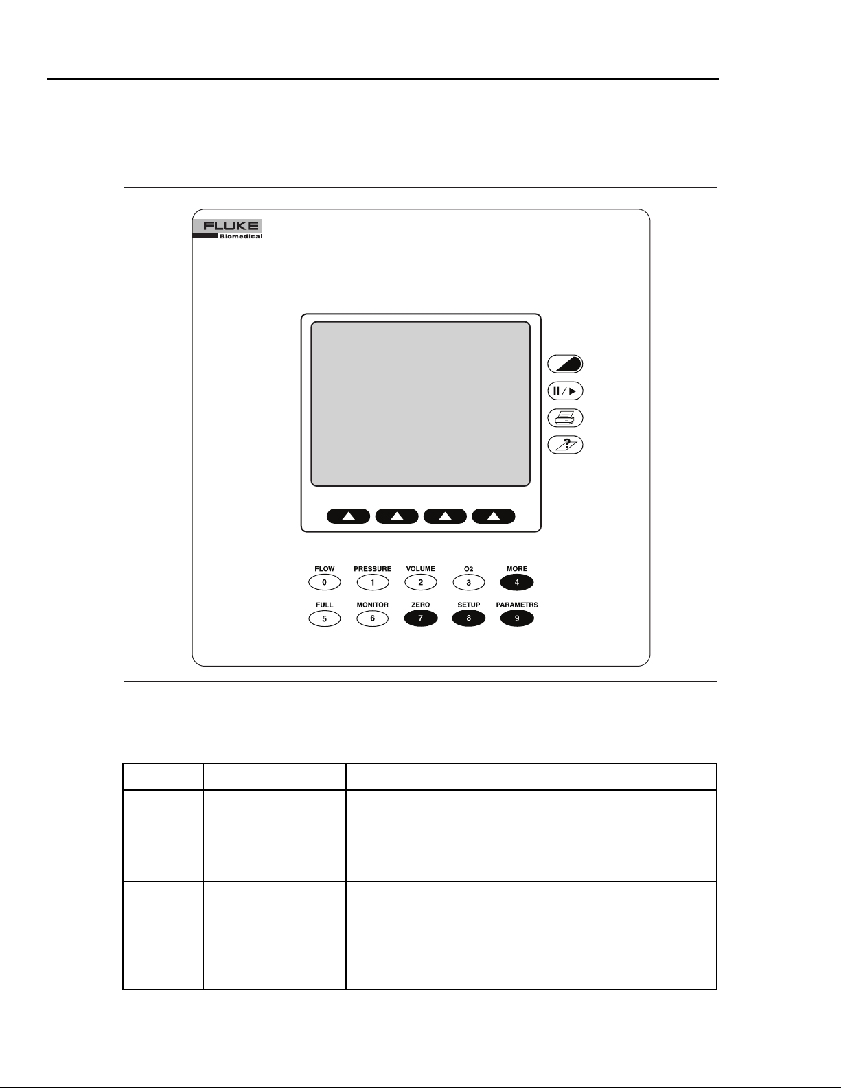
Front Panel Details
Figure 1-3 shows details of the Analyzer front panel, and Table 1-6 describes the various
keys, their icons, and functions.
VT PLUS HF
GAS FLOW ANALYZER
TEST MODES
1-8
Figure 1-3. Analyzer Front Panel
Table 1-6. Front Panel Functions
Icon Name Function
E
F
Contrast Adjustment This key adjusts the screen contrast to match the user’s
preference. Each time the key is pressed, the screen becomes
lighter. When the minimum contrast is reached, the screen is set
to the maximum contrast and the screen can be made lighter
until the preferred setting is achieved.
Pause/Resume This key pauses the plots and numeric data on the screen to
allow further examination of the data, or for transcription of the
data by the user. After the screen has been paused, a second
press of the Pause/Resume key resumes the plot. Note: The
Analyzer stops sampling the transducers while in the Pause
mode.
fec011.eps
Page 21

Introduction and Specifications
Table 1-6. Functions (cont.)
Icon Name Function
Instrument Familiarity 1
G
H
D
:
;
<
Print This key prints the current data to the printer. The mode and
format of the printout is set using the printer options function
selected under the setup menu.
Help This key displays help for any screen. A brief description of the
screen and of the options available from that screen is provided
when help is pressed.
Soft Keys These are four programmable keys located directly below the
display. Each display mode has unique options assigned to its
soft keys.
FLOW/0 Key This key selects the flow mode on the Analyzer. The flow mode
displays signal, instantaneous numeric value and statistical data
for the high or low flow signal. This key is also the 0 key for
numeric data entry.
PRESSURE/1 Key This key selects the pressure mode. The pressure mode
displays the signal, instantaneous numeric value, and statistical
data for the high, low, or airway pressure signal. This key is also
the 1 key for numeric data entry.
VOLUME/2 Key This key selects the volume mode. The volume mode displays
the signal, instantaneous numeric value, and statistical data for
the volume signal. This key is also the 2 key for numeric data
entry.
=
>
?
@
O2/3 Key This key selects the oxygen mode. The oxygen mode displays
the signal, instantaneous numeric value and statistical data for
the oxygen signal. This key is also the 3 key for numeric data
entry.
MORE/4 Key This key selects other tests such as the Leak test and the Trend
test. This key is also the 4 key for numeric data entry.
FULL/5 Key This key selects the full breath parameters mode. The full mode
displays all of the breath parameters calculated by the Analyzer
following every breath. Note that one of the breath-detect
settings must be enabled to observe volume signals or data.
Refer to System Setup for breath detection settings. This key is
also the 5 key for numeric data entry.
MONITOR/6 Key This key selects the monitor mode. The monitor mode displays
the signal and instantaneous value for three of the signals
measured by the Analyzer. Alternatively, the lower of the three
plots may be replaced by selected breath parameters. The user
can select the signals and/or parameters that are displayed. This
key is also the 6 key for numeric data entry.
1-9
Page 22

VT Plus HF
Operators Manual
Table 1-6. Functions (cont.)
Icon Name Function
A
B
C
ZERO/7 Key This key initiates the zero function in the Analyzer. All of the
pressure and differential pressure (flow) sensors in the Analyzer
must be periodically zeroed or calibrated to a zero reference.
When zero is selected, the device measures the zero value of
the selected signal for flow measuring. The Analyzer can be set
to periodically call of the zero function. Refer to System Setup
for Zero Mode Descriptions. This key is also the 7 key for
numeric data entry.
SETUP/8 Key This key accesses the Analyzer configuration and setup
screens. When this key is pressed, a menu is displayed. The
soft keys are used to navigate the menu. From this menu, other
sub-menus are accessible to adjust the various configuration
settings. The details of this menu and its sub-menus are
described later. This key is also the 8 key for numeric data entry.
PARAMETERS/9 Key This key selects which of the breath parameters are displayed in
the various modes. Each mode screen has space to display 4 of
the breath parameters. Using the parameters function, the four
breath parameters can be selected. Note that if 4 parameters
are already selected, then no more can be selected until one of
the previously selected parameters is cleared. Also note that the
parameters that are selected only apply to the screen that the
Analyzer was in when the parameters key was pressed. This
key is also the 9 key for numeric data entry.
Specifications
The following are general, performance, breath parameter accuracy specifications for the
Analyzer.
General Specifications
Display ................................................... 320 x 240 LCD with CFL backlight
Viewing Area ......................................... 3 in x 4 in (10.1 cm x 8.2 cm) Blue on white background
Operational Modes ............................... Manual mode for simple tests or troubleshooting; computer-control
Output Ports.......................................... RS232 serial port and parallel-printer port
Operating Environmental Conditions
Temperature Range........ ................ 10 °C to 40 °C
Ambient Humidity................... ......... 0 - 80 % non-condensing to 31 °C, decreasing to 50 % at 40 °C
Barometric Pressure......................... 8 to 18 psia
Vibration .......................................... Devices intended to be used on tabletop or other stable surface.
Storage Environmental Conditions
Temperature Range ........................-25 to 50 °C
Humidity........................................... 0 to 95 % non-condensing °C
Power Requirements
Maximum Over-voltage ...................264 V ac
Input Voltage Range .......................100 to 240 V ac
Input Frequency Range ................. 50/60 Hz
mode, using RS232 serial port for special applications; use of Analyzer
with VT for Windows PC software for recording graphs and logging
data to a computer
1-10
Page 23

Introduction and Specifications
Power Consumption ....................... <132 VA
Fuse Rating .................................... 0.5 A, Slo-Blo
Specifications 1
Performance Specifications
Low-Pressure Port
Maximum Applied Pressure............. 60 psi
Operating Pressure ......................... (Differential) ±500 mmHg (±10 psi)
Span Accuracy ................................ ±0.80 % of reading or ±1.5 mmHg, whichever is greater
Frequency Response ...................... >10 Hz
Resolution........................................ 0.1 mmHg
Sample Rate ...................................100 Hz
(Common-mode) 30 psi
Note
Fluid pressure may be applied to the positive port; however, fluids should
be kept from entering the pressure port by using a suitable length of
connection tubing.
High-Pressure Port
Maximum Applied Pressure............ 150 psi
Operating Pressure ........................ ±100 psi
Span Accuracy ............................... ±1 % of reading or ±0.3 psig, whichever is greater
Frequency Response ..................... >10 Hz
Resolution....................................... 0.1 psi
Sample Rate................................... 100 Hz
Fluid pressure may be applied to the positive port; however, fluids should
be kept from entering the pressure port by using a suitable length of
connection tubing.
Airway Pressure
Maximum Applied Pressure............. 20 psi
Operating Pressure ........................ ±120 cmH
Span Accuracy ............................... ±0.75 % of reading or r 0.5 cmH
Frequency Response ..................... >25 Hz or t10-90 <40 ms, whichever is greater
Resolution....................................... 0.1 cmH
Sample rate .................................... 100 Hz
Airway pressure is internally tapped off the proximal flow sensor port,
which is the port closest to the exhaust port on the Analyzer.
Continuous Flow
Low Flow ............................................... ±(2 % of reading and 1 % of range)
High Flow............................................... ±(2 % of reading and 1 % of range)
Volumetric Flow
High-Flow Port
Maximum Flow Rate........................ (absolute value) 500 lpm
Operating Flow Range.................... ±300 lpm
Accuracy......................................... ±2.0 % of range
Resolution....................................... 0.01 lpm
Note
2
O
2
Note
O
O, whichever is greater
2
1-11
Page 24

VT Plus HF
Operators Manual
Frequency Response. .................... >25 Hz or t10-90 <40 ms, whichever is greater
Sample Rate................................... 100 Hz
Dynamic Resistance....................... <2.00 cmH
Low-flow Dropout............................ 25 lpm
Breath Detect Threshold................. (user settable) 2.0 lpm
Volume Range................................ >±60 l
O @ 60 lpm
2
Notes
• Tidal Volume Accuracy ±3 % of reading or ±10 ml, whichever is
greater
• Volume Accuracy tested to 7 liters.
• Flow accuracy is specified for dry air or oxygen.
• Do not use with humidified gases.
Low Flow Port
Maximum Flow Rate........................(absolute value) 50 lpm
Operating Flow Range.................... ±25 lpm
Accuracy......................................... ±1.0 % of range
Resolution....................................... 0.01 lpm flow >1 lpm; 0.001 lpm flow <1 lpm
Frequency Response ...................... >25 Hz or t10-90 <40 ms, whichever is greater
Sample Rate................................... 100 Hz
Dynamic Resistance....................... <2.5 cmH
Low-flow Dropout............................ 0.01 lpm
Breath Detect Threshold................. (user settable) 0.50 lpm
Volume Range ............................... >±60 l
O @ 5 lpm
2
Note
• Tidal Volume Accuracy ± 3 % of reading or ±5 ml, whichever is
greater
• Volume Accuracy tested to 1 liter
• Flow accuracy is specified for dry air or oxygen.
• Do not use with humidified gases.
• Below 0.25 lpm, measurement accuracy is obtained by allowing the
Analyzer to fully warm up, and manually zeroing before reading or
documenting a measurement.
Breath Parameter Accuracy Specifications
Breath parameter accuracy specifications are listed in Table 1-7.
Note
If a choice of readings is indicated by an “or”, choose whichever is
greater; for example, 3 % or 250 ml.
1-12
Page 25

Introduction and Specifications
Table 1-7. Breath Parameter Accuracy Specifications
Parameter Resolution Range Accuracy
Specifications 1
Inspiratory and
Expiratory Tidal Volume
0.1 ml As specified in
high/low-flow spec
As specified in
high/low-flow spec
Minute Volume 0.001 lpm 0-60 l 3 %
Breath Rate 0.1 bpm 0.5 – 150 bpm 1 %
Inspiratory to Expiratory
0.01 1:200 to 200:1 2 % or .1
Time Ratio (I:E Ratio)
Peak Inspiratory
0.1 cmH2O ±120 cmH2O ±3 % or 1 cmH2O
Pressure
Inspiratory Pause
0.1 cmH2O ±120 cmH2O ±3 % or 1 cmH2O
Pressure
Mean Airway Pressure 0.1 cmH2O ±80 cmH2O ±3 % or 0.5 cmH2O
Positive End-expiratory
0.1 cmH2O -5 to 40 cmH2O ±3 % or 0.5 cmH2O
Pressure (PEEP)
Lung Compliance1 0.1 ml/cmH2O 0 - 150 ml/cmH2O ±5 % or 5 ml/cmH2O
Inspiratory Time 0.01 sec 0 - 60 sec 0.5 % or 0.02 sec
Inspiratory Hold Time 0.01 sec 0 - 60 sec 1 % or 0.1 sec
Expiratory Time 0.01 sec 0 - 90 sec 0.5 % or 0.01 sec
Expiratory Hold Time 0.01 sec 0 - 90 sec 1 % or 0.1 sec
Peak Expiratory Flow 0.01 lpm 0 - 300 lpm 3 % or 2 lpm
Peak Inspiratory Flow 0.01 lpm 0 - 300 lpm 3 % or 2 lpm
Flow Bias2 0.01 lpm 0 - 30 lpm 2 % or 0.5 lpm
1
Inspiratory pause time >0.5 sec
2
Expiratory pause time >0.5 sec
1-13
Page 26

VT Plus HF
Operators Manual
Accessories
Operators manual 2137275
VT for Windows PC software 2392054
Standard bi-directional RS232 serial cable 2238659
Tilt stand 2133387
Table 1-8 lists standard accessories provided with the Analyzer. Table 1-9 lists optional
accessories.
Table 1-8. Standard Accessories
Item Part Number
Power cable
US
Schuko
UK
Australia
Accessory kit containing the following items: 2131367
One bacterial filter for external connection to the flow ports 2133712
One adapter, DISS O2 nut and nipple with ¼ in ID hose barb 2391777
4’ Tubing 1/8” ID clear w/blue stripe 2391848
Two 22 mm ID x 22 mm ID tubing adapters 2133305
Two 22 mm OD x 22 mm OD tubing adapters 2133291
Two tapered 15 mm OD x 22 mm OD tubing adapters 2133269
Two tapered 15 mm OD x 15 mm OD tubing adapters 2133278
Two tapered 15 mm ID x 15 mm ID tubing adapters 2133284
Two narrow bore tubing adapters 2133322
Two flexible 15 mm ID x 22 mm ID tubing adapters 2133310
Two 1/4" NPT male to 1/8" ID tubing barb fitting (Nylon) 2133240
2238562
769422
2238570
658641
1-14
Two 1/4" NPT male to 1/16" ID to bulkhead connection 2133202
Two luer to barb fittings 2213679
Two replacement fuses 0.5 A slow-blow 2133932
One DISS Handtight Nut/Nipple to 1/4” ID hose barb adapter 2216329
Certificate of Calibration – Data Sheet NA
Page 27

Introduction and Specifications
Table 1-9. Optional Accessories
Item Part Number
Soft vinyl carrying case 2222822
Hard-sided protective carrying case 2248587
Soft-sided carrying case for ACCU-LUNG 2397628
Accessories 1
Graphics Printer
110 V Citizen IDP3110
220 V Citizen IDP3110
D25 male to Centronics parallel cable 2238072
ACCU-LUNG Lung Simulator with Soft-sided
carrying case (2397628)
2248762
2719653
2387318
1-15
Page 28

VT Plus HF
Operators Manual
1-16 2-1
Page 29

Chapter 2
Connection and Setup
Title Page
Connecting the Analyzer ................................................................................... 2-3
Pneumatic Connections ................................................................................. 2-3
High Flow (Inlet and Exhaust).................................................................. 2-3
Low Flow (Inlet and Exhaust)................................................................... 2-3
High Pressure (+ and -) ............................................................................. 2-3
Low Pressure (+ and -).............................................................................. 2-4
Test System Setup ......................................................................................... 2-4
Bi-directional Flow Mode ......................................................................... 2-4
Unidirectional Flow Mode ........................................................................ 2-5
Printer Cable Attachment .............................................................................. 2-6
Using the Setup Screen ...................................................................................... 2-7
Setting Testing Parameters ................................................................................ 2-7
Gas Settings................................................................................................... 2-8
Gas Type ................................................................................................... 2-8
Gas Temperature ....................................................................................... 2-9
Ambient Temperature ............................................................................... 2-9
Relative Humidity ..................................................................................... 2-9
Correction Mode............................................................................................ 2-10
Barometric Pressure....................................................................................... 2-10
Breath Detection............................................................................................ 2-11
Inspiratory/Expiratory Tidal Volumes........................................................... 2-12
Zero Mode ..................................................................................................... 2-12
Setting Analyzer Operating Parameters............................................................. 2-13
Time............................................................................................................... 2-13
Date ............................................................................................................... 2-14
Date Format ................................................................................................... 2-14
Demo Data..................................................................................................... 2-14
Filtering ......................................................................................................... 2-15
Display Calibration Date on Startup Screen.................................................. 2-15
Serial Mode ................................................................................................... 2-15
Printer Options............................................................................................... 2-16
Printer Type............................................................................................... 2-16
Graphics .................................................................................................... 2-17
Audio Levels ................................................................................................. 2-17
General ...................................................................................................... 2-17
Page 30

VT Plus HF
Operators Manual
Keypad ...................................................................................................... 2-17
Errors......................................................................................................... 2-18
Restore Defaults ............................................................................................ 2-18
Utilities .............................................................................................................. 2-20
Oxygen Sensor Calibration............................................................................ 2-20
System Diagnostics ....................................................................................... 2-21
Linearization.................................................................................................. 2-21
Unlock Calibration ........................................................................................ 2-22
Information ........................................................................................................ 2-22
2-2
Page 31

Connection and Setup
Connecting the Analyzer 2
Connecting the Analyzer
The Analyzer can be connected to a ventilator and a test load in either a bidirectional or
unidirectional flow configuration.
Pneumatic Connections
The following is a description of various pneumatic connections on the Analyzer.
High Flow (Inlet and Exhaust)
The outer diameter of the high flow ports is a standard 22 mm fitting to allow connection
using patient hoses. The inner diameter of the high flow ports is designed to accept a 15
mm male respiratory fitting such as endotracheal tubes, gas sampling adapters, etc.
W Caution
To avoid damage to the Analyzer or adverse affects on its
performance, follow these guidelines:
• Pressure inside the high flow port should not exceed ±120
cmH
O.
2
• Measure only dry gases with the high flow port. Do not use
this port to measure exhaled or artificially humidified
gases.
Low Flow (Inlet and Exhaust)
The outer diameter of the low-flow ports is a standard 15 mm to allow connection with
standard respiratory fittings such as gas sampling Y-pieces and gas sampling adapters.
The inner lumen of the low-flow ports are threaded to accept a standard ¼ in NPT fitting.
To avoid damage to the Analyzer or adverse affects on its
performance, follow these guidelines:
• Pressure inside the low flow port should not exceed ±120
cmH
O.
2
• Measure only dry gases with the low flow port. Do not use
this port to measure exhaled or artificially humidified
gases.
High Pressure (+ and -)
The high-pressure ports are primarily designed for testing wall and tank pressurized gas
sources. The connector mates to standard oxygen DISS fittings as used on oxygen supply
hoses. Note that only the + side can be used to measure fluid pressure.
To avoid damage to the Analyzer or adverse affects on its
performance, follow these guidelines:
W Caution
W Caution
• Applied differential pressure to either side of the high-
pressure port should not exceed 100 psi.
• The negative (-) side of the high-pressure port cannot be
used to measure fluid pressure.
2-3
Page 32

VT Plus HF
Operators Manual
Low Pressure (+ and -)
Test System Setup
The low-pressure ports connect using standard luer fittings. Note that only the + side can
be used to measure fluid pressure.
W Caution
To avoid damage to the Analyzer or adverse affects on its
performance, follow these guidelines:
• Pressures applied to either side of the low-pressure port
should not exceed ±500 mmHg.
• Negative (-) side of the low-pressure port cannot be used to
measure fluid pressure.
High- or low-flow ranges can be used for ventilator testing. One test setup is measuring
ventilator parameters using a test lung. Either a bi-directional flow mode, as shown in
Figure 2-1 or a unidirectional flow mode, as shown in Figures 2-2 and 2-3, below can be
chosen; however, the bi-directional mode is preferred.
Bi-directional Flow Mode
1. Connect the ventilator, using a Y-piece adapter, to the flow inlet port on the right of
the Analyzer.
2. Connect the flow exhaust port on the left to the test lung using standard breathing
hoses.
Ventilator
Figure 2-1. Connecting the Analyzer in a Bi-Directional Flow Mode
3. Ensure that the breath detection mode is set to bi-directional.
a. Go into Setup.
Inspiratory Hose
Expiratory Hose
Analyzer
TEST
LUNG
OutletInlet
fec002.eps
2-4
b. Choose Settings
c. Choose Breath Detect and modify as needed
Page 33

Connection and Setup
Connecting the Analyzer 2
Unidirectional Flow Mode
Alternatively, the Analyzer can be used to measure only inspiratory or expiratory gas
flow, as described below.
Inspiratory Testing
1. Connect the inspiratory hose to the flow port on the right of the Analyzer.
2. Connect the flow exhaust port on the left to the test lung using standard breathing
hoses.
Ventilator
Figure 2-2. Connecting the Analyzer to the Inspiratory Limb of the Breathing Circuit
3. Ensure that the breath detection mode is set to Unidirectional Inspiratory.
a. Go into Setup
b. Choose Settings
c. Choose Breath Detect and modify as needed
Expiratory Testing
1. Connect the expiratory hose to the flow port on the right side of the Analyzer.
Inlet
VT PLUS HF
Expiratory Hose
Outlet
Inspiratory Hose
TEST
LUNG
fec008.eps
2. Connect the flow exhaust port on the left to the ventilator using standard breathing
hoses.
Inspiratory Hose
Ventilator
VT PLUS HF
Expiratory Hose
Outlet
Figure 2-3. Connecting the Analyzer to the Expiratory Limb of the Breathing Circuit
Inlet
2-5
TEST
LUNG
fec009.eps
Page 34

VT Plus HF
Operators Manual
3. Ensure that the breath detection mode is set to Unidirectional Expiratory.
a. Go into Setup
b. Choose Settings
c. Choose Breath Detect and modify as needed
The Analyzer displays a screen showing the flow of gas delivered by the ventilator:
The instantaneous flow rate displays in large numbers in the upper right portion of the
screen. The flow statistics (min., max and average) are shown below in the center right
portion of the screen. A subset of the breath parameters is shown below the flow plot.
The following adjustments can be made to the screen:
• Switch between the high- and low-flow ports – Press the RANGE soft key.
• Change the measurement units (LPM, CFM, LPS) – Press the UNITS soft key.
• Change the plot scaling – Press the RESCALE soft key. The new scaling is based on
the minimum and maximum values shown in the statistics area.
• Erase the plot and re-initialize the statistics and breath parameters – Press the
CLEAR soft key.
• See more information in any screen – Press the HELP key.
• Pause and resume the plot screen, respectfully – Press the PAUSE/RESUME key.
Printer Cable Attachment
The printer uses a D25 male to Centronics parallel cable for parallel printing. This cable
is available from Fluke (part #2238072) or from most electronic supply outlets.
To attach the parallel cable:
fec049.bmp
2-6
1. Connect the 36-pin end for the Centronics type parallel cable to the printer’s parallel
input connector.
2. Attach the 25-pin male end of the parallel cable to the 25-pin connector on the back
of the Analyzer.
Page 35

Connection and Setup
Using the Setup Screen 2
Using the Setup Screen
To use the Setup screen:
1. Press the SETUP/8 key. The Setup screen displays:
The options are:
• Settings – a menu for choosing options that affect flow and measurement on the
Analyzer
• System – a menu for choosing options that affect how information on the
Analyzer is set up such as time and date
• Utility – used for system service and calibration only
• Information – product information about the Analyzer, such as serial number
and copyright
2. Use the S and T soft keys to highlight an option.
3. Press the ENTER soft key to select the option.
4. Press the BACK soft key to return to the previous menu.
Setting Testing Parameters
To adjust the settings:
1. From the Setup screen, highlight Settings and press the ENTER soft key. The
Settings menu displays.
2. Change settings to pre-selected options or to numeric values by highlighting the
option and pressing the MODIFY soft key.
fec027.bmp
For example, if one selects Correction Mode then presses MODIFY, he can scroll
through the available Correction Mode options. If one selects an option that requires
a numeric entry, such as BD Threshold and press MODIFY, the entered data is
cleared, and the field can accept numeric input from the keypad until the ENTER key
is pressed.
2-7
Page 36

VT Plus HF
Operators Manual
Gas Settings
Note
The option displayed when exiting the settings screen is saved and used for
future measurements.
The following is a description of each setting.
This setting tells the Analyzer what type of gas is flowing through the high- and low-flow
ports. The Analyzer uses this information to improve the accuracy of the flow
calculations.
Note
Failure to enter the correct value causes the flow and volume calculations
to be in error.
To modify the gas settings:
1. From the Setup menu, highlight Settings and press the ENTER soft key.
2. Highlight Gas Settings and press the MODIFY soft key.
Depending on the option, a value can be pre-selected or input from the keypad. The
following is a description of each of the options.
Gas Type
The possible values for Gas Type are shown in Table 2-1.
User Defined User selects custom gas mixture. This option requires the VT for Wondows
Table 2-1. Gas Type Values
Value Description
Air Standard room air
N2 100 % Nitrogen
N2O 100 % Nitrous Oxide
CO2 100 % Carbon Dioxide
O2 100 % Oxygen
Heliox 30 % Oxygen and 70 % Helium blend
N2O bal O2 Measured Oxygen balance Nitrous Oxide
He bal O2 Measured Oxygen balance Oxygen Helium
N2 bal O2 Measured Oxygen balance Nitrogen
PC software.
Note
For balance gas settings, the oxygen concentration is measured using the
Analyzer oxygen sensor located on the high-flow port. If the low-flow port
is to be used, allow gas to flow through both high- and low-flow ports so
that the oxygen can be measured.
2-8
To modify the gas type:
Page 37

Connection and Setup
Setting Testing Parameters 2
1. From the Gas Settings menu, highlight Gas Type.
2. Press the MODIFY soft key until the desired value displays.
3. Press the BACK soft key to return to the Settings menu.
Gas Temperature
This setting is the temperature of the gas flowing through the high- or low-flow port. The
Analyzer uses this information to improve the accuracy of the flow measurements. All
temperatures are in °C.
To enter a gas temperature:
1. From the Gas Settings menu, highlight Gas Temperature.
2. Press the MODIFY soft key to display the value field.
3. Input the desired value from the keypad.
Note
The Analyzer accepts temperatures between 0 and 99 °C. No decimal
values or fractions are allowed.
4. Press the ENTER soft key to save the change or the ESCAPE soft key to cancel the
change.
5. Press the BACK soft key to return to the Settings menu.
Ambient Temperature
This setting is the room temperature air flowing through the high-or low-flow ports.
To change ambient temperature:
1. From the Gas Settings menu, highlight Ambient Temp.
2. Press the MODIFY soft key to display the value field.
3. Input the desired value from the keypad.
The Analyzer accepts temperatures between 0 and 99 °C. No decimal
values or fractions are allowed.
4. Press the ENTER soft key to save the change or the ESCAPE soft key to cancel the
change.
5. Press the BACK soft key to return to the Settings menu.
Relative Humidity
This setting is the relative humidity in the air flowing through the high- and low-flow
ports and is used only for STPD and BTPS corrections. The relative humidity is not used
in calculating the effective viscosity on the Analyzer; however, the gas calculator in the
VT Plus PC software does use relative humidity in determining the effective viscosity of
user-defined gases.
Note
To change relative humidity:
1. From the Gas Settings menu, highlight Rel. Humidity.
2. Press the MODIFY soft key to display the value field.
2-9
Page 38

VT Plus HF
Operators Manual
Correction Mode
3. Input the desired value from the keypad.
4. Press the ENTER soft key to save the change or the ESCAPE soft key to cancel the
change.
5. Press the BACK soft key to return to the Settings menu.
Note
Use only dry gases with the Analyzer. Do not use with heated humidified gases; using
humidified gases at room temperature may cause flow measurement errors of up to 1 %
of reading for near-saturated, non-condensing gases.
This setting calculates the flow volume of the air flowing through the high- or low-flow
ports. This value should match the correction mode of the device under test (DUT).
To change correction mode:
1. From the Gas Settings menu, highlight Correction Mode.
2. Press the MODIFY soft key to toggle to the desired value.
3. Press the ENTER soft key to save the change or the ESCAPE soft key to cancel the
change.
4. Press the BACK soft key to return to the Settings menu.
Barometric Pressure
The Analyzer constantly measures the barometric pressure and displays it on the Full
Test screen. This setting allows the user to fine-tune the barometric pressure
measurement. The difference between the value measured by the Analyzer and the
entered value is applied to future Analyzer measurements as a offset correction factor.
The correction factor is stored in nonvolatile memory and is remembered when the
Analyzer is turned off and on.
Setting Barometric Pressure Units
These settings represent the various units available to measure barometric pressure such
as mmHg.
To change the barometric pressure units:
1. From the Gas Settings menu, highlight Baro Press Units.
2. Press the MODIFY soft key to toggle to the desired value.
3. Press the ENTER soft key to save the change or the ESCAPE soft key to cancel the
change.
4. Press the BACK soft key to return to the Settings menu.
Entering a Barometric Pressure Value
To enter a barometric pressure value:
2-10
1.
From the Gas Settings menu, highlight Barometric Press.
2. Press the MODIFY soft key to display the value field.
3. Input the desired value from the keypad.
Page 39

Connection and Setup
Note
The Analyzer accepts barometric pressure values between 0 and 999
mmHg. No decimal values or fractions are allowed.
4. Press the ENTER soft key to save the change or the ESCAPE soft key to cancel the
change.
5. Press the BACK soft key to return to the Settings menu.
Breath Detection
The Analyzer can be used to measure parameters on a breath-to-breath basis. To measure
breath parameters, the mode of breath detection must be set. The breath detection options
are shown in Table 2-2 .
Table 2-2. Breath Detection Options
Option Description
Setting Testing Parameters 2
Q
N
P
Off
Setting Breath Detection Mode
To select the breath-detection mode:
1. From the Gas Settings menu, highlight Breath Detect.
2. Press the MODIFY soft key to toggle to the desired value.
3. Press the ENTER soft key to save the change or the ESCAPE soft key to cancel the
change.
4. Press the BACK soft key to return to the Settings menu.
Bi-directional breath detection – Use this breath detection mode when analyzing
both inspired and expired breath data or when the Analyzer is connected
between the load (lung simulator) and the Y-piece in the breathing circuit.
Unidirectional inspired only – Use this breath detection mode when the Analyzer
is analyzing only inspired breaths or when the Analyzer is connected in the
inspired limb of the ventilator breathing circuit.
Unidirectional expired only – Use this breath detection mode when the Analyzer
is analyzing only expired breaths or when the Analyzer is connected in the
expired limb of the ventilator breathing circuit.
Use this mode to measure continuous flow and volume without attempting to
detect breaths. Use this mode to integrate a flow over a long period of time.
Setting Breath Detect Threshold
The Analyzer breath detection algorithm uses a flow rate threshold that the flow must
cross to trigger a change in the breath phase. Higher flow rate thresholds yield less
sensitive breath detection. Lower thresholds yield more sensitive breath detection.
To enter the breath detect threshold:
1. From the Gas Settings menu, highlight LF Threshold to adjust the low-flow
threshold or BD Threshold to adjust the high-flow threshold.
2. Press the MODIFY soft key to display the value field.
3. Input the desired value from the keypad.
2-11
Page 40

VT Plus HF
Operators Manual
Inspiratory/Expiratory Tidal Volumes
4. Press the ENTER soft key to save the change or the ESCAPE soft key to cancel the
change.
5. Press the BACK soft key to return to the Settings menu.
The Analyzer measures tidal volume when performing ventilator measurements. This
option allows the user to choose between the expiratory or the inspiratory tidal volume.
The default setting is inspiratory.
Note
This setting applies only when the bi-directional breath-detection mode is
selected.
To change between inspiratory and expiratory tidal volume:
1. From the Gas Settings menu, highlight Bi-Dir Tidal Vol.
2. Press the MODIFY soft key to toggle to the desired value.
3. Press the ENTER soft key to save the change or the ESCAPE soft key to cancel the
change.
4. Press the BACK soft key to return to the Settings menu.
Zero Mode
All pressure and differential pressure (flow) sensors in the Analyzer must be periodically
zeroed or calibrated to a zero reference. This zero function can be set to occur
automatically at pre-determined intervals or only when the user requests the function by
pressing the key labeled ZERO/7. When a zero occurs, valves inside the device open the
sensors to ambient pressure and measure the zero value to be subtracted from future
measurements.
Because no breath parameters are calculated for any breath in which a
zero occurs, it may be desirable to turn off automatic zeroing for a short
while during a critical test.
To turn automatic zeroing on or off:
1. From the Gas Settings menu, highlight Zero Mode.
2. Press the MODIFY soft key to toggle to the desired value.
3. Press the ENTER soft key to save the change or the ESCAPE soft key to cancel the
4. Press the BACK soft key to return to the Settings menu.
Note
change.
2-12
Page 41

Connection and Setup
Setting Analyzer Operating Parameters 2
Setting Analyzer Operating Parameters
To adjust system information:
1. From the Setup screen, highlight System and press the ENTER soft key. The
System menu displays:
Time
fec032.bmp
2. Change settings to pre-selected options or to numeric values by highlighting the
option and pressing the MODIFY soft key.
For example, if one selects Filtering, then presses MODIFY, he can scroll through
the available Filtering options. If one selects an option that requires a numeric entry,
such as Time, and presses MODIFY, the entered data is cleared, and the field can
accept numeric input from the keypad until the ENTER key is pressed.
Note
The option displayed when exiting the settings screen is saved and used for
future measurements.
The following is a description of how to change each system setting. All of these options
are accessed from the System menu of the Setup screen.
The Analyzer displays hours, minutes, and seconds on the display. However, the user can
set only hours and minutes.
To set the time:
1. Highlight Time.
2. Press the MODIFY soft key to display the value field.
3. Input the desired value from the keypad. Enter time in the HHMM format where HH
is the hours in 25-hour format (0 to 23) and MM is the minutes, a number between 0
and 59.
Note
For hour and minute values less than 10, enter a leading zero. For
example, if the time is 9:05, enter 0905.
2-13
Page 42

VT Plus HF
Operators Manual
Date
4. Press the ENTER soft key to save the change or the ESCAPE soft key to cancel the
change.
5. Press the BACK soft key to return to the Settings menu.
Note
For hour and minute values less than 10, enter a leading zero. For
example, if the time is 9:05, enter 0905.
The Analyzer displays the date with MM as the month, DD as the date, and YYYY as the
year.
To enter the date:
1. Highlight Date.
2. Press the MODIFY soft key to display the value field.
3. Input the desired value from the keypad. Enter the date with MM the number
between 1 and 12, corresponding to the month; DD the number between 1 and 31,
corresponding to the day of the month; and YYYY the year. See Date Format,
below.
For values of month and date less than 10, enter a leading zero. For
example, if the month is February, enter 02.
4. Press the ENTER soft key to save the change or the ESCAPE soft key to cancel the
change.
5. Press the BACK soft key to return to the Settings menu.
Date Format
The Analyzer has two date formats as shown below: MM/DD/YYYY and
DD/MM/YYYY
To change the format:
1. Highlight Date Format.
2. Press the MODIFY soft key to toggle to the desired value.
3. Press the ENTER soft key to save the change or the ESCAPE soft key to cancel the
change.
4. Press the BACK soft key to return to the Settings menu.
Demo Data
This setting allows the user to show recorded data on screen without needing to connect
the Analyzer to a ventilator or do any measurements. The word DEMO appears on the
menu bar when this mode is engaged. The recorded data is for demonstration purposes.
Note
2-14
To select the demo data function:
1. Highlight Demo Data.
2.
Press the MODIFY soft key to toggle to the desired value.
Page 43

Connection and Setup
Setting Analyzer Operating Parameters 2
3. Press the ENTER soft key to save the change or the ESCAPE soft key to cancel the
change.
4. Press the BACK soft key to return to the Settings menu.
Filtering
This setting is used to adjust the transition of signals on the flow meters. The filter has
four levels: Soft, Medium, Hard, and None.
Note
When filtering is on, full test parameters are invalid.
To change the filtering level:
1. Highlight Filtering.
2. Press the MODIFY soft key to toggle to the desired value.
3. Press the ENTER soft key to save the change or the ESCAPE soft key to cancel the
change.
4. Press the BACK soft key to return to the Settings menu.
Display Calibration Date on Startup Screen
Use this option to control whether the calibration due date appears on the startup screen.
To select whether the calibration due date is shown on the startup screen:
1. Highlight Display Cal Date.
2. Press the MODIFY soft key to toggle between YES and NO.
3. Press the ENTER soft key to save the change or the ESCAPE soft key to cancel the
change.
4. Press the BACK soft key to return to the Settings menu.
Serial Mode
Use this option to control what data is available through the Analyzer serial port. The
possible options are shown in Table 2-3.
Table 2-3. Serial Port Options
Option Description
Comp Ctrl
RT200 A serial mode that emulates the Allied RT200 serial communications
Computer Control – specialized serial communications used by the VT for
Windows PC Software; contact your sales representative for the protocol if
needed.
None No serial communications
2-15
Page 44

VT Plus HF
Operators Manual
Printer Options
To select the serial mode options follow these steps:
1. Highlight Serial Mode.
2. Press the MODIFY soft key to toggle to the desired value.
3. Press the ENTER soft key to save the change or the ESCAPE soft key to cancel the
change.
4. Press the BACK soft key to return to the Settings menu.
This setting allows selection of the print format for information. The Analyzer can be
connected to various printers, and the following printer languages are supported:
• HP PCL/3 (graphics/text or text only)
• Epson P1 (graphics/text or text only)
• ASCII printers in both 40 and 80 characters per line (text only).
Read the printer user manual to determine if it is compatible with these printer languages.
Note
A printer may require a special dip-switch setting to support a given
language.
To select the printer options, highlight Printer Options. The Printer Options screen
appears:
Printer Type
To choose a printer:
1. Highlight Printer Type and press the MODIFY soft key to toggle to the desired
printer type.
fec033.bmp
2-16
2. Press the ENTER soft key to save the change or the ESCAPE soft key to cancel the
change.
3. Press the BACK soft key to return to the Settings menu.
Page 45

Connection and Setup
Setting Analyzer Operating Parameters 2
Graphics
To choose the format of reports shown:
1. Highlight Graphics and press the MODIFY soft key to toggle between Graphics
or Text Only.
2. Press the ENTER soft key to save the change or the ESCAPE soft key to cancel the
change.
3. Press the BACK soft key to return to the Settings menu.
Audio Levels
This setting adjusts the level of sound for the functions of the Analyzer.
To adjust the sound, highlight Audio Levels. The Audio Levels screen appears:
General
To adjust the general audio level:
1. Highlight General and press the MODIFY soft key to toggle between Low , High,
2. Press the ENTER soft key to save the change or the ESCAPE soft key to cancel the
3. Press the BACK soft key to return to the Settings menu.
Keypad
When keypad buttons are pushed, a beep signals this action. This option adjusts the sound
level of that beep.
To adjust the sound level of the keypad:
1. Highlight Keypad and press the MODIFY soft key to toggle between Low , High,
2. Press the ENTER soft key to save the change or the ESCAPE soft key to cancel the
3. Press the BACK soft key to return to the Settings menu.
or Off.
change.
or Off.
change.
fec034.bmp
2-17
Page 46

VT Plus HF
Operators Manual
Errors
Restore Defaults
When an error is made, the Analyzer signals it with a beep. This option adjusts the sound
level of that beep.
To adjust the sound level of errors:
1. Highlight Errors and press the MODIFY soft key to toggle between Low , High, or
Off.
2. Press the ENTER soft key to save the change or the ESCAPE soft key to cancel the
change.
3. Press the BACK soft key to return to the Settings menu.
This option returns all values to the factory defaults listed below, but does not change the
device calibration.
To restore defaults:
From the System menu, highlight Restore Defaults. The Analyzer restores system
values to the default, displays a Restoring to defaults. Please wait message.
After a few seconds, a beep indicates defaults are restored, and the display returns to the
System menu. Factory defaults are shown in Table 2-4.
Table 2-4. Factory Defaults
System
Date Format MM/DD/YYYY
Demo Data Off
Filtering None
Display Cal Date Yes
Serial Mode None
Printer Options
Printer Type None
Graphics Text Only
Audio Levels
General Low
Keypad Low
Errors Low
2-18
Settings
Gas Settings
Gas Type Air
Gas Temperature 22 °C
Ambient Temperature 22 °C
Page 47

Connection and Setup
Table 2-4. Factory Defaults (cont.)
Settings (cont.)
Rel. Humidity 33 °C
Correction Mode ATP
Baro Press Units mmHg
Barometric Pressure Actual ambient pressure
Breath Detect Bidirectional
LF BD Threshold 0.50 lpm
HF BD Threshold 2.00 lpm
Bi-Dir Tidal Vol Inspiratory
Zero Mode Auto
Displays
Flow
Setting Analyzer Operating Parameters 2
Range High Flow
Units LPM Air
Scale -100.00 to +100.00
Pressure
Range Airway
Units cmH20
Scale -100.00 to +100.00
Volume:
Units L Air
Scale 0.000 to 3.00
O2
Units % O2
Scale 0.0 to 100.0
Monitor:
Top Zone High Flow
Units lpm Air
Middle Zone Airway [Pressure]
Units cmH20
Bottom Zone Volume
Units L Air
Parameters
Tidal Vol, Base Flow, O2, Gas selected (checked) All others de-selected (un-checked)
2-19
Page 48

VT Plus HF
Operators Manual
Utilities
Note
These settings are required by service technicians in servicing the Analyzer.
To access the utility functions:
1. From the Setup screen, highlight Utilities and press the ENTER soft key. The
Utilities menu displays:
Oxygen Sensor Calibration
Recalibrate the oxygen sensor with 100 % oxygen and dry air at the beginning of any day
in which oxygen concentrations are to be measured.
To calibrate the oxygen sensor:
1. Apply 10 lpm of dry air to the high-flow inlet or exhaust.
2. Use the S and T soft keys to highlight Oxygen Calibration.
3. Press the ENTER soft key. The O2 Calibration screen displays.
fec035.bmp
2-20
fec075.bmp
Page 49

Connection and Setup
Utilities 2
4. Press the ZERO soft key.
5. Press OK to start 21 % O
SKIP.
6. Verify that the O2 reading is 20.9 ±0.1 %.
7. Press the CAL soft key.
8. Apply 10 lpm of dry 100 % oxygen to the high-flow inlet or exhaust.
9. Press OK to start 100 % O2 calibration. Allow the full 2-minute period. Do not press
SKIP.
10. Verify that the O
11. Press the BACK soft key to return to the Utilities menu.
If the oxygen sensor cannot be calibrated, it may need to be replaced. Refer
to Maintenance, Service, and Calibration: Oxygen Sensor Replacement.
System Diagnostics
These functions are for the technical service personnel to use while repairing the
Analyzer. They include Zero All, AD Diagnostics, and Signal Diagnostics.
Linearization
This option is most useful to technical service personnel repairing the Analyzer. There is
no input, but the calibration data for each sensor is stored and displayed, so a checksum
test can be performed to make sure the sensor data is still valid.
calibration. Allow the full 2-minute period. Do not press
2
reading is 100 ±0.1 %.
2
Note
To check linearization data:
1. From the Utilities menu, highlight Linearization. The Linearizaion Info screen
displays:
fec036.bmp
2. Press the BACK soft key to return to the Utilities menu.
2-21
Page 50

VT Plus HF
Operators Manual
Unlock Calibration
Information
This function is for technical service personnel to use while repairing the Analyzer. When
the Unlock Calibration is highlighted and the ENTER soft key is pressed, calibration
is unlocked, and the display returns to the Utilities menu.
This setting shows Analyzer product information, such as serial number and copyright.
To read system information:
1. From the Setup screen, highlight Information and press the ENTER soft key. The
Information screen displays:
2. Press OK to return to the Setup screen.
fec037.bmp
2-22
Page 51

Chapter 3
Operation
Title Page
Measured Signals............................................................................................... 3-3
High Flow...................................................................................................... 3-3
Low Flow ...................................................................................................... 3-3
Airway Pressure............................................................................................. 3-3
Low Pressure ................................................................................................. 3-3
Barometric Pressure....................................................................................... 3-4
High-Pressure Measurement.......................................................................... 3-4
Oxygen Concentration................................................................................... 3-4
Calculated Breath Parameters........................................................................ 3-4
Screen Objects ................................................................................................... 3-6
Title Bar......................................................................................................... 3-7
Data Plots ...................................................................................................... 3-7
Breath Parameters.......................................................................................... 3-7
Breath Detection Icons .................................................................................. 3-8
Instantaneous Numeric Data.......................................................................... 3-9
Statistics......................................................................................................... 3-9
Selecting Breath Parameters .............................................................................. 3-10
Flow Screens...................................................................................................... 3-11
High-Flow Screen.......................................................................................... 3-11
Low-Flow Screen .......................................................................................... 3-12
Pressure Screens ................................................................................................ 3-13
High-Pressure Screen .................................................................................... 3-13
Low Pressure Screen ..................................................................................... 3-14
Airway Pressure Screen................................................................................. 3-15
Volume Screen................................................................................................... 3-16
Oxygen Screen................................................................................................... 3-17
Full Breath Parameters Test Screen................................................................... 3-18
Monitor Screen .................................................................................................. 3-19
Units of Measure................................................................................................ 3-20
Special Functions............................................................................................... 3-21
Trend Test...................................................................................................... 3-21
Leak Test ....................................................................................................... 3-24
Stacked Volume Test..................................................................................... 3-27
RT200 Emulation Mode ................................................................................ 3-28
Assist Test ..................................................................................................... 3-31
High Frequency Oscillator Mode .................................................................. 3-32
3-1
Page 52

VT Plus HF
Operators Manual
3-2
Page 53

Operation
Measured Signals 3
Measured Signals
The Analyzer measures the following signals:
• High flow
• Low flow
• Airway pressure
• Low pressure
• Barometric pressure
• High Pressure
• Oxygen concentration
• Calculated breath parameters
High Flow
The Analyzer has a high-flow (±300 LPM), bi-directional flow measurement. Flow
measurements can be either static flows (no breath variations) or ventilator waveforms
(i.e., both an expiratory and an inspiratory phase). The flow measurement is made using a
differential pressure drop across a resistive screen mesh. This flow measurement can be
used for pediatric/adult ventilators or for determining the performance of many types of
flow meters. Valves switch between the low-flow and the high-flow measurements
depending on the range selected in the display flow screens.
Low Flow
The Analyzer has a low-flow (±25 LPM), bi-directional flow measurement. The flow
measurements can be either static (no breath variations) or ventilator waveforms (i.e.,
both an expiratory and an inspiratory phase). Flow measurements are made using a
differential pressure drop across a resistive screen mesh. The low-flow signal can be used
for infant/neonatal ventilators or for determining the performance of many other types of
flow meter. Valves switch between the low-flow and the high-flow measurements
depending on the range selected in the display flow screens.
Airway Pressure
The airway pressure is measured from a tap off of the proximal (near the exhaust port) of
the flow sensor housings. This tap is connected to a ±120 cmH
generates the airway pressure signal. Valves switch between the low-flow and the highflow measurements. When the low-flow port is selected, the airway pressure is measured
off the low-flow port. Likewise, when the high-flow port is selected the airway pressure
is measured off the high-flow port. Use the RANGE soft key from any of the flow
screens to select which flow port (high or low) airway pressure is measured from.
Low Pressure
This is a dual-port connection consisting of a (+) positive and a (-) negative pressure port.
The differential pressure range is ±500 mmHg. This pressure measurement can be used
for any pressure differential or gauge pressure in the given range. The transducer is
capable of measuring fluid pressure on the (+) positive port as indicated on the label.
O pressure sensor that
2
3-3
Page 54

VT Plus HF
Operators Manual
Barometric Pressure
High-Pressure Measurement
Oxygen Concentration
A barometric pressure measurement is provided by the Analyzer. The barometer can read
absolute pressures from 8 to 18 PSIA. The barometer is also used in the automatic ATP,
BTPS, and STPD conversions for flow and volume measurements. The barometric
pressure signal can be fine tuned using the procedure described in System Setup.
The high-pressure measurement is made from a dual-port connection consisting of a (+)
positive and a (-) negative pressure port. The differential pressure range is ±100 psi. This
pressure measurement can be used for any pressure differential or gauge pressure in the
given range. The transducer is capable of measuring fluid pressure on the (+) positive
port as indicated on the label.
Oxygen concentration is measured through the high-flow port of the system on the rear
panel bulkhead fitting. An integrated sensor measures the oxygen percent of the gas in
the high flow channel of the Analyzer. The range for this sensor is 0 % to 100 %. The
oxygen cell is mounted inside the enclosure on the rear bulkhead for the high-flow
circuit. The fuel cell must be replaced approximately once a year. Oxygen readings are
compensated for airway pressure.
Calculated Breath Parameters
From the primary flow and pressure measurements, the Analyzer is designed to calculate
breath rate, % leak, and base flow. A breath detection algorithm determines the various
phases of a ventilator breath and calculates the parameters listed in Table 3-1.
3-4
Page 55

Operation
Table 3-1. Parameters Calculated by the Analyzer
Parameter Abbreviation How Calculated
Inspiratory Time In Time Time of the inspiratory period including the
inspiratory hold time
Expiratory Time Ex Time Time of the expiratory period including the
expiratory hold time
Inspiratory Hold Time In Hold Time of the End Inspiratory State
Expiratory Hold Time Ex Hold Time of the End Expiratory State
Measured Signals 3
Inspiratory to Expiratory
Time
Inspiratory Hold
Pressure
Positive End-Expiratory
Pressure
Mean Airway Pressure MAP Mean pressure over the entire breath
Peak Inspiratory
Pressure
Tidal Volume Tidal Vol Total volume accumulated over the Inspiratory
Minute Volume Minute Vol Expiratory Tidal Volume times the respiratory
Peak Inspiratory Flow
Rate
Peak Expiratory Flow
Rate
Compliance N/A Expiratory Tidal Volume divided by the difference
Ratio I:E Ratio of the inspiratory time to the Expiratory
Time
IPP Average pressure during the End Inspiratory
State
PEEP Average pressure during the End Expiratory
State
PIP Maximum pressure during the Inspiratory Time
Time
rate in breaths per minute; reported as an eightbreath average
PIF Maximum of the absolute value of the Flow Rate
measured during the Inspiratory Time
PEF Maximum of the absolute value of the Flow Rate
measured during the Expiratory Time
of the Inspiratory Hold Pressure and PEEP
3-5
Page 56

VT Plus HF
Operators Manual
Screen Objects
Classes of information shown on the Analyzer display are a title bar, various breath
detection icons, statistics, data plots, instantaneous numeric value of plotted data, and
selected breath parameters, as shown in Figure 3-1 and listed in Table 3-2.
1
2
3
Figure 3-1. Information Shown on Analyzer Display
Table 3-2. Display Components
Label Description
4
5
6
A Title bar
B Data plots
fec010.eps
3-6
C Parameters
D Icons
E Instantaneous numeric data
F Statistics
These screen options are described below.
Page 57

Operation
Screen Objects 3
Title Bar
Each screen includes a title bar that shows the screen or mode name on the left. A number
indicating the screen number is shown in a small box on the right of the title bar:
9
Indicates the screen number
Data Plots
Except the FULL screen, each screen includes a data plot that shows a measured signal
(flow, pressure volume, or O
) vs. time:
2
New data is added to the plot starting on the left and progressing to the right. When the
plot has progressed to the right edge, the plot restarts on the left side of the plot. One line
of data from the previous plot is removed ahead of the new plot.
When a new screen is selected, the plot is displayed using a default plot range. Pressing
the CLEAR soft key restarts the plot and clears all previously plotted data and calculated
statistics. Pressing the RESCALE key changes the window of the data plot to a more
appropriate range based on the minimum and maximum values in the Statistics area.
fec039.bmp
fec045.bmp
Note
After pressing CLEAR, allow one full cycle to pass before pressing
RESCALE.
Breath Parameters
Every screen can display up to four breath parameters:
fec047.bmp
These parameters are displayed only when breath detection is enabled. See Special
Functions for instructions on how to enable breath detection. Parameters are updated
following every breath. Units of measure for breath parameters are fixed. See
Introduction: Specifications for a listing of breath parameters and units. See Selecting
Breath Parameters for instructions on selecting which parameters are displayed for each
of the modes.
3-7
Page 58

VT Plus HF
Operators Manual
Breath Detection Icons
The breath-detection icon is located on the right side of the title bar. Various icons and
their meanings are listed in Table 3-3.
Table 3-3. Breath Detection Icons
Icon Meaning
O
Q
P
N
W
R
S
T
U
V
L
M
K
A large number 0 to the right of the title bar indicates that automatic sensorzeroing mode has been selected.
Bi-directional breath detection: Use this breath-detection mode when
analyzing both inspired and expired breath data or when the Analyzer is
connected between the load (lung simulator) and the Y-piece in the breathing
circuit.
Unidirectional expired only: Use this breath-detection mode when the
Analyzer is analyzing only expired breaths or when the Analyzer is connected
in the expired limb of the ventilator breathing circuit.
Unidirectional inspired only: Use this breath-detection mode when the
Analyzer is analyzing only inspired breaths or when the Analyzer is connected
in the inspired limb of the ventilator breathing circuit.
ATP: This indicates the conversion of gas flow and volume to ambient
temperature and pressure.
BTPS: This indicates the conversion of gas flow and volume to body
temperature of 37 °C with 100 % relative humidity.
STPD0,: This indicates the conversion of gas flow and volume to a standard
temperature of 0 °C and a standard barometric pressure of 760 mmHg.
STPD21: This indicates the conversion of gas flow and volume to a standard
temperature of 21 °C and a standard barometric pressure of 760 mmHg.
Inspiratory Tidal Volumes: This indicates that the reported tidal volumes are
measured over the inspiratory phase of the breath. This only applies to the
bidirectional breath-detect mode.
Expiratory Tidal Volumes: This indicates that the reported tidal volumes are
measured over the expiratory phase of the breath. This only applies to the
bidirectional breath-detect mode.
Light (Soft) Filtering: This indicates that the filtering option is turned on and
the filter is set to light or soft filtering. In this mode, all of the signals (flow and
pressure) have a Digital Signal Processing (DSP) low-pass filter applied. This
is used when measuring very noisy signals. None of the ventilator parameters
are valid when the filtering is turned on.
Medium Filtering: This indicates that the filtering option is turned on and the
filter is set to medium filtering. In this mode, all of the signals (flow and
pressure) have a Digital Signal Processing (DSP) low-pass filter applied. This
is used when measuring very noisy signals. None of the ventilator parameters
are valid when the filtering is turned on.
Hard Filtering: This indicates that the filtering option is turned on and the filter
is set to hard filtering. In this mode, all of the signals (flow and pressure) have
a Digital Signal Processing (DSP) low-pass filter applied. This is used when
measuring very noisy signals. None of the ventilator parameters are valid
when the filtering is turned on.
3-8
Page 59

Operation
Screen Objects 3
Instantaneous Numeric Data
The digital value of the plotted signal is displayed to the right of each plot:
This value is updated approximately twice a second. This value is the average of the
signal over the previous 500 milliseconds.
The Analyzer allows the user to select the desired units for each of the measured signals.
For example, pressures can be displayed in mmHg, kPa, bar, mbar, atm, inH2O, inHg,
cmH2O or mmHg. Pressing the UNITS soft key changes the unit of measurement for the
displayed signal value. Pressing the UNITS soft key repeatedly causes the instrument to
cycle through the various possible units. The selected units of measure remain in memory
even if the mode has been changed or if the Analyzer has been turned off. The selected
gas type appears in the area below the UNITS soft key.
Statistics
On each of the screens, except Full Breath Parameters and Monitor, the minimum,
maximum, and average values of the plot are displayed to the right of the plot, as shown
below:
fec046.bmp
fec044.bmp
These values are calculated continually until a new screen is selected or until the CLEAR
soft key is pressed.
3-9
Page 60

VT Plus HF
Operators Manual
Selecting Breath Parameters
The Analyzer calculates 17 breath parameters for every breath:
fec048.bmp
The user can select up to four of these parameters to be displayed with each of the
screens.
To select parameters for display on a specific screen:
1. Select the screen for which the parameters are to be added. For example, to select
parameters for addition to the Flow screen, press the FLOW/0 key.
2. Press the PARAMETERS/9 key to display all possible parameters. An X in the
small box adjacent to a parameter name indicates that the parameter is to be added.
An empty box indicates that the parameter is not to be added.
3. Use the soft keys labeled Sand T to highlight parameters.
4. Press the ENTER soft key to select (add) or deselect (not add) a parameter. Only
four parameters can be viewed on a screen; therefore, an existing parameter must be
deselected from the list before a new parameter can be selected.
5. Repeat steps 3 and 4 above for each additional parameter to be changed. Selecting the
Set all screens to the same parameters option in the parameters screen
displays the currently selected parameters on all screens. If this option is deselected
after having been in effect, previous parameter selections for each screen must be
reselected.
6. Press the EXIT soft key to return to the previous screen.
3-10
Note
Parameter selections are retained even after the Analyzer has been
powered off.
Page 61

Operation
Flow Screens 3
Flow Screens
There are two types of flow screen, high-flow and low-flow, based on which Analyzer
flow port is used.
High-Flow Screen
The High-Flow screen displays the signal and statistics for flow in the high-flow port of
the Analyzer.
fec049.bmp
Range Press the RANGE soft key to change from a low-flow screen to a high-
flow screen or back again.
Units Press the UNITS soft key to change the units of measure for the high-
flow screen. Possible units of measure for this screen include:
LPM Liters per minute
CFM Cubic feet per minute
LPS Liters per second
ml/min Milliliters per minute
ml/sec Milliliters per second
Re-scale Press the RESCALE soft key to change the scale on the plot of data to a
more appropriate window of values.
Note
RESCALE uses the current min/max values to
determine plot limits.
Clear Press the CLEAR soft key to reset the statistics and re-start the plot.
Allow one full waveform cycle to plot before pressing RESCALE.
The user can select the breath parameters displayed on this screen by following the
instructions under Selecting Breath Parameters.
3-11
Page 62

VT Plus HF
Operators Manual
Low-Flow Screen
The Low-Flow screen displays the signal and statistics for the flow in the low-flow port
of the Analyzer.
fec050.bmp
Range Press the RANGE soft key to change from a high-flow screen to a low-
flow screen or back again.
Units Press the UNITS soft key to change the units of measure for the low-
flow screen. Possible units of measure for this screen include:
LPM Liters per minute
CFM Cubic feet per minute
LPS Liters per second
ml/min Milliliters per minute
ml/sec Milliliters per second
Re-scale Press the RESCALE soft key to change the scale on the plot of data to a
more appropriate window of values.
Note
RESCALE uses the current min/max values to
determine plot limits.
Clear Press the CLEAR soft key to reset the statistics and re-start the plot.
The user can select the breath parameters displayed on this screen by following the
instructions under Selecting Breath Parameters.
3-12
Page 63

Operation
Pressure Screens 3
Pressure Screens
There are two types of pressure screen, high-pressure and low-pressure, based on which
Analyzer pressure port is used.
High-Pressure Screen
The High-Pressure screen displays the signal and statistics for the pressure signal from
the high-pressure ports of the Analyzer.
fec051.bmp
Range Press the RANGE soft key to change between low pressure, airway
pressure, and high-pressure screens.
Units Press the UNITS soft key to change the units of measure for the high-
pressure screen. Possible units of measure for this screen include:
mbar millibar = .001 Bar
bar 14.7 PSIG (Barometric)
mmHg millimeters of mercury
inHg inches of mercury
cmH
inH
O centimeters of water
2
O inches of water
2
PSIG pounds per square inch
atm atmospheres
kPa kilopascals
Re-scale Press the RESCALE soft key to change the scale on the plot of data to a
more appropriate window of values.
Note
RESCALE uses the current min/max values to
determine plot limits.
Clear Press the CLEAR soft key to reset the statistics and re-start the plot.
The user can select the breath parameters displayed on this screen by following the
instructions under Selecting Breath Parameters.
3-13
Page 64

VT Plus HF
Operators Manual
Low Pressure Screen
The Low-Pressure screen displays the signal and statistics for the pressure signal from the
low-pressure ports of the Analyzer.
fec052.bmp
Range Press the RANGE soft key to change between low pressure, airway
pressure, and high-pressure screens.
Units Press the UNITS soft key to change the units of measure for the low-
pressure screen. Possible units of measure for this screen include:
mbar millibar = .001 Bar
bar 14.7 PSIG (Barometric)
mmHg millimeters of mercury
inHg inches of mercury
cmH
inH
O centimeters of water
2
O inches of water
2
PSIG pounds per square inch
atm atmospheres
kPa kilopascals
Re-scale Press the RESCALE soft key to change the scale on the plot of data to a
more appropriate window of values.
Note
RESCALE uses the current min/max values to
determine plot limits.
3-14
Clear Press the CLEAR soft key to reset the statistics and re-start the plot.
The user can select the breath parameters displayed on this screen by following the
instructions under Selecting Breath Parameters.
Page 65

Operation
Pressure Screens 3
Airway Pressure Screen
The Airway Pressure screen displays the signal and statistics for whichever range is
currently selected in either the high- or low-flow ports of the Analyzer. This screen
measures the pressure in a ventilated test lung. The airway pressure displayed is that for
the selected high- or low-flow port.
Range Press the RANGE soft key to change between low pressure, airway
pressure, and high-pressure screens.
Units Press the UNITS soft key to change the units of measure for the airway-
pressure screen. Possible units of measure for this screen include:
mbar millibar = .001 Bar
bar 14.7 PSIG (Barometric)
mmHg millimeters of mercury
inHg inches of mercury
cmH
inH
O centimeters of water
2
O inches of water
2
PSIG pounds per square inch
atm atmospheres
kPa kilopascals
Re-scale Press the RESCALE soft key to change the scale on the plot of data to a
more appropriate window of values.
Note
RESCALE uses the current min/max values to
determine plot limits.
Clear Press the CLEAR soft key to reset the statistics and re-start the plot.
The user can select the breath parameters displayed on this screen by following the
instructions under Selecting Breath Parameters.
3-15
Page 66

VT Plus HF
Operators Manual
Volume Screen
The Volume screen displays the signal and statistics for the volume signal.
fec053.bmp
The volume signal is the integral of the flow signal measured in either the high or low
flow ports. The flow port that is integrated is selected by selecting the high- or low-flow
range from within the flow screen.
Flow Zero Press the FLOW ZERO soft key to zero the flow reading.
Units Press the UNITS soft key to change the units of measure for the volume
screen. Possible units of measure for this screen include:
l Liters
ml Milliliters
CF Cubic Feet
Re-scale Press the RESCALE soft key to change the scale on the plot of data to a
more appropriate window of values.
Note
RESCALE uses the current min/max values to
determine plot limits.
Clear Press the CLEAR soft key to reset the statistics and re-start the plot.
The user can select the breath parameters displayed on this screen by following the
instructions under Selecting Parameters.
3-16
Note
The volume signal is integrated from either the high- or low-flow signals.
To select which flow signal is used to calculate volume:
1. Press the FLOW/0 key.
2. Press the RANGE soft key until the screen corresponding to the desired flow signal
(high or low) displays.
Page 67

Operation
Oxygen Screen 3
Oxygen Screen
The Oxygen screen displays the signal and statistics for the oxygen sensor.
fec054.bmp
The Analyzer measures oxygen in the high-flow port. If oxygen in the low-flow port is to
be measured, the flow of gas must be passed through the high-flow port also to measure
oxygen.
Re-scale Press the RESCALE soft key to change the scale on the plot of data to a
more appropriate window of values.
Note
RESCALE uses the current min/max values to
determine plot limits.
Clear Press the CLEAR soft key to reset the statistics and re-start the plot.
The user can select the breath parameters displayed on this screen by following the
instructions under Selecting Breath Parameters. Refer to Connection and Setup: Utilities:
Oxygen Sensor Calibration for instructions.
3-17
Page 68

VT Plus HF
Operators Manual
Full Breath Parameters Test Screen
The Full Test screen displays all of the breath parameters calculated by the Analyzer.
fec055.bmp
Note
Breath detection must be enabled for breath parameters to be calculated.
See System Setup for instructions on enabling breath detection.
Trend Press the TREND soft key to print the trend of a single parameter. See
Special Functions for a more description of the trend function
Clear Press the CLEAR soft key to reset the statistics and re-start the plot.
If asterisks appear for a parameter value, the parameter is either invalid for the current
breath detect mode or the system does not have sufficient information to accurately
calculate the parameter. For example, Base Flow is invalid during bi-directional breath
detection mode because the base flow is seen only in the inspiratory and expiratory limbs
of the ventilator circuit. In another example, it would be impossible to measure the
inspiratory hold pressure during the expiratory-only mode.
Note
The Assist Pressure (Assist) and the Minimum Pressure (Min Pres) are not
available for trending and cannot be added to other screens using the
parameter selection. Refer to Special Functions for instructions on Assist
Mode testing.
3-18
Page 69

Operation
Monitor Screen 3
Monitor Screen
The Monitor screen shows three signals and their corresponding values.
fec056.bmp
Alternatively, the lower signal can be replaced by a set of four breath parameters. The
user can select which signals are displayed on the monitor screen.
Select Press the SELECT soft key to change the position of the plot that can be
altered using the ASSIGN and UNITS soft keys. The vertical cursor bar
on the right side of the display moves, indicating the plot area selected.
Assign Press the ASSIGN soft key to change which signal is plotted in the
selected position. Four breath parameters can be displayed in place of a
signal plot in the lowest position. The user can select the parameters
displayed in this screen.
Units Press the UNITS soft key to change the units of the signal and the units of
the instantaneous value for the plot in the selected position. The possible
units for each of the various signals are the same as the units that can be
displayed in the screens that display that signal exclusively.
Re-scale Press the RESCALE soft key to change the scale on the plot of data to a
more appropriate window of values.
3-19
Page 70

VT Plus HF
Operators Manual
Units of Measure
The Analyzer has the capability to display the above signals and parameters in the
following units of measure shown in Table 3-4 .
Table 3-4. Available Units of Measure
Unit Description
Flow
lpm Liters per minute
f3/min Cubic feet per minute
l/sec Liters per second
ml/min Milliliters per minute
ml/sec Milliliters per second
Low/High/Barometric/Airway Pressure
PSIG Pounds per square inch gauge
kPa Kilopascals
bar 14.7 PSIG
mbar millibar = .001 Bar
atm Atmosphere
inH20 Inches of water
inHg Inches of mercury
cmH20 Centimeters of water
mmHg Millimeters of mercury
Volume
l Liters
F3 Cubic Feet
ml Milliliters
3-20
Page 71

Operation
Special Functions 3
The Analyzer has conversion factors for gas, volume, and flow measurements, as shown
in Table 3-5.
Table 3-5. Available Conversion Factors
Conversion Factor Description
ATP Conversion for gas flow and volume to ambient temperature
and pressure
STPD0 Conversion for gas flow and volume to a standard temperature
of 0 °C and a standard barometric pressure of 760 mmHg
STPD21 Conversion for gas flow and volume to a standard temperature
of 21 °C and a standard barometric pressure of 760 mmHg
BTPS Conversion for gas flow and volume to body temperature of 37
°C with 100 % relative humidity
Special Functions
Trend Test
The Analyzer provides an automated Trend test that checks a single breath parameter
over an extended period of time to see if it deviates from limits set by the user. The limits
are set as a percent variation from the initial measured value.
To access the Trend test screen, use either of the following procedures:
1. Press the FULL/5 key to display the breath parameters.
2. Press the soft key TREND soft key.
Or
1. Press the MORE/4 key.
2. Use the S and T soft keys to highlight Trend Test.
3. Press the soft key ENTER soft key. The Trend Test Setup screen displays.
fec057.bmp
To set test parameters:
3-21
Page 72

VT Plus HF
Operators Manual
1. Use the S and T soft keys to highlight Test Parameter.
2. Press the MODIFY soft key until the desired breath parameter displays. The most
recent measurement of the selected parameter is displayed as the Current Value.
3. Use the S and T soft keys to highlight % Limit.
4. Press the MODIFY soft key, then use the keypad to enter the percent change
representing a deviation from acceptable limits. Percent values range from 1 to 99.
Remember to enter leading zeros for values less than 10. For example, 5 % is entered
as 05 %.
5. Press the ENTER soft key.
6. Use the S and T soft keys to highlight Use Printer.
7. Press the MODIFY soft key. If Yes is selected, a report is printed that list all breath
parameters with a time/date stamp every time an incident occurs.
To run the test:
1. Ensure that the ventilator is on and that steady-state conditions are reached. Monitor
the Current Value displayed to ensure that the breath parameter is as expected.
Press the START soft key to begin testing. While the test is in progress, the Trend
Test screen displays the parameter being tested, the current and starting values, and
the % difference between the two values. The allowable % deviation limit, the
number of tests taken, and the number of breaths (incidents) in which the limit has
been exceeded is also displayed.
3-22
fec059.bmp
2. To terminate the test, press the STOP soft key. A sample Trend Test report is shown
below.
Page 73

Operation
Special Functions 3
TREND TEST REPORT
6/13/2000 10:45 VT PLUS HF S/N: 4294967295
Control #: __________________ S/N: __________________
Tech: __________________
Incident Report
Test Parameter: Minute Vol Elapsed Time: 0:00:05
Current Value: 40.333 L Starting Value: 28.686 L
% Difference: 41 % % Limit: 5 %
# of Tests: 1 # of Incidents: 1
Parameters:
Minute Vol: 40.333 L Breath Rate: 29 bpm
Tidal Vol: 1384.8 ml Ex Time: 0.9 sec
PIP: 109.42 LPM In Time: 1.1 sec
PEP: 113.91 LPM Ex Hold: 0.0 sec
Base Flow: ***** LPM In Hold: 0.0 sec
Compliance: ***** ml/cmH2O I:E Ratio: 1.2:1
O2: 18.5 % PIP: 1.9 cmH2O
Baro Press: 645.1 mmHg MAP: 0.0 cmH2O
Gas: Air IPP: 0.0 cmH2O
PEEP: 0.0 cmH2O
Final Report
Test Parameter: Minute Vol Starting Value: 28.686 L
Starting Time: 10:45:30 Ending Time: 10:45:37
Elapsed Time: 0:00:07 % Limit: 5 %
# of Incidents: 1 # of Tests: 1
3-23
Page 74

VT Plus HF
Operators Manual
Leak Test
The Analyzer allows the user to test the leak rate of a sealed vessel or test lung. A Leak
test can be done using the high pressure, low pressure, or airway pressure signals to
measure the leak rate of a sealed vessel or test lung.
W Caution
To avoid damage to the Analyzer, be sure that maximum
pressure ratings are not exceeded when performing a Leak test.
See Specifications for absolute maximum pressure ratings for
each pressure port.
To access the Leak test screen:
1. Press the MORE/4 key.
2. Use the S and T soft keys to highlight Leak Test.
3. Press the ENTER soft key. The Leak Test Setup screen displays.
3-24
fec061.bmp
To set test parameters:
1. On the Leak Test Setup screen, press the S and T soft keys to highlight
Pressure Channel.
2. Press the MODIFY soft key until the desired pressure channel is selected.
Note
If Airway is selected, the airway transducer is connected to the currently
selected flow channel. Both flow channels can be tested; however, the
appropriate channel must be selected using the RANGE function in the
Flow Mode screen.
3. To enter the compliance of the test chamber (test lung) press the S and T soft keys
to highlight Compliance.
4. Press the MODIFY soft key. Use the keypad to enter the compliance in l/cmH
O. Be
2
sure to use leading zeros so that a number is entered for all five digits.
5. To enter the duration of the test, press the S and T soft keys to highlight Test
Time.
6. Press the MODIFY soft key.
Page 75

Operation
Special Functions 3
7. Use the keypad to enter the duration of the Leak test in hours, minutes, and seconds.
Six digits must be entered to set the test time. The time is entered in the following
format: HHMMSS (HH is the hours (0-99), MM is the minutes (0-59) and SS is the
seconds (0-59). Be sure to use leading zeros to enter values less than 10. For
example, to enter a time of 1:09:05, press the following sequence of keys: 0, 1, 0, 9,
0, 5).
To run the test:
1. After all of the test parameters are set, pressurize the test chamber (test lung).
2. Press the START soft key to begin testing. A screen similar to the one shown is
displayed.
fec062.bmp
3. The display shows a pressure plot and instantaneous pressure value to the right of the
plot. Parameters below the pressure plot show the entered compliance, the time of
day that the test was started, and the calculated test results.
4. Press the STOP soft key to terminate the test or let the test time elapse. In either
case, a Leak test result displays.
fec063.bmp
3-25
Page 76

VT Plus HF
Operators Manual
A sample Leak Test Report is shown below.
Fluke Biomedical Corporation
1/2/2000 3:05 VT PLUS HF S/N: 166752
Control #: __________________ S/N: __________________
Tech: __________________
Leak Test:
Low Press 0.02 Kpa
Compliance: 0.00 ml/cmH2O
Start Press: 0.00 Kpa
Start Time: 03:05:13
Vol Lost: 0.0 ml
Leak Rate: 0.07 cmH2O/s
Elapse Time: 00:00:03
Parameters:
Minute Vol: 0.000 L Breath Rate: 0 bpm
Tidal Vol: 0.0 ml Ex Time: 0.0 sec
PIP: 0.00 LPM In Time: 0.0 sec
PEP: 0.00 LPM Ex Hold: 0.0 sec
Base Flow: 0.00 LPM In Hold: 0.0 sec
Compliance: 0.0 ml/cmH2O I:E Ratio: *****
O2: 20.6 % PIP: 0.0 cmH2O
Baro Press: 766.6 mmHg MAP: 0.0 cmH2O
Gas: Air IPP: 0.0 cmH2O
PEEP: 0.0 cmH2O
3-26
Page 77

Operation
Special Functions 3
Stacked Volume Test
The Stacked Volume test measures the volume of multiple breaths to determine the
accuracy of the ventilator in accumulating volume.
To access the Stacked Volume test:
1. Press the MORE/4 key.
2. Use the S and T soft keys to highlight Stacked Volume Test.
3. Press the ENTER soft key.
4. Press the MODIFY soft key.
5. Use the keypad to enter the number of breaths for the test and press the ENTER soft
key.
To run the test:
1. Press the START or AUTO soft key to begin the test. The display changes to show
the progress of the test:
fec067.bmp
The values shown are described below:
Total Volume – The total volume of all breaths together
Last Volume – The volume of the last breath taken
Avg. Volume – The average volume of all breaths taken
Num. Of Breaths – The total number of breaths taken
Total # Breaths – The total number of breaths to be taken
Note
If a stacked volume test is started with the START soft key, the test
accumulates the requested number of breaths and ends. If the test is started
using the AUTO soft key, the test automatically restarts after the requested
number of breaths have accumulated.
2. When the test is complete, press the STACK soft key to start a new stacked volume
test or press the EXIT soft key to exit.
3-27
Page 78

VT Plus HF
Operators Manual
RT200 Emulation Mode
The Analyzer can emulate RT200 serial port communications. This mode is used for
some ventilator automated test procedures.
To set the RT200 emulation mode:
1. From the Setup screen, select System.
2. Use the S and T soft keys to highlight Serial Mode.
3. Press the MODIFY soft key to change Serial Mode to RT200.
To access the RT200 Emulation mode use either of the following procedures:
1. Press the MORE/4 key.
2. Use the S and T soft keys to highlight RT200 Emulation Mode.
3. Press the ENTER soft key.
Or
1. Press the SETUP/8 key.
2. Use the S and T soft keys to highlight SYSTEM.
3. Press the ENTER soft key.
4. Use the S and T soft keys to highlight Serial Mode.
5. Press the MODIFY soft key until RT200 displays.
6. Press the BACK soft key to return to the Setup screen.
7. Press the BACK soft key again to exit the Setup screen and display the RT200
screen.
fec069.bmp
3-28
In the emulation mode, serial (RS232) commands can be sent to the Analyzer in the
format of the communication protocol used by the RT200.
The status of the RT200 special functions are displayed in the boxes: 00, 01, F1, F2. The
meaning of the special functions can vary depending on the active function. Refer to the
RT200 Calibration Analyzer – Operation Manual from Allied Healthcare Products, Inc.
The Command box displays the active command and the units of the command, (F41 3
lit. O2%/N2). If the peak mode is active, the Command box displays peak at the end of
Page 79

Operation
Special Functions 3
the command string. When a command is received, it is displayed in the box named
Received String. Refer to Serial Interface for the RT200 Calibration Analyzer System –
Operation Manual from Allied Healthcare Products, Inc. for the format of serial
commands.
The RT200 Functions supported by the Analyzer are listed in Table 3-6.
Table 3-6. Supported RT200 Functions
Command Description
F09 Reset
F11 Low Pressure Measurement – (20 cmH2O)
F12 Low Pressure Measurement – (250 cmH2O)
F13 Low Pressure Measurement – (185 mmHg)
F21 High Pressure Measurement – (20 psi)
F22 High Pressure Measurement – (100 psi)
F23 High Pressure Measurement – (5170 mmHg)
F31 Low Flow Measurement – (O2% / N2)
F32 Low Flow Measurement – (Air)
F33 Low Flow Measurement – (O2% / N2O)
F35 High Flow Measurement – (O2% / N2)
F36 High Flow Measurement – (Air)
F37 High Flow Measurement – (O2% / N2O)
F41 Tidal Volume – (O2% / N2)
F42 Tidal Volume – (Air)
F43 Minute Volume – (O2% / N2)
F45 Respiratory Rate
F46 T
F47 T
F48 I:E Ratio
inspiratory
expiratory
3-29
Page 80

VT Plus HF
Operators Manual
The soft keys for the RT200 screen are:
SETUP RS232 – displays a screen for setting the baud rate, number of data bits, and the
terminator character:
fec071.bmp
These settings affect only the RT200 emulation mode and not the other serial
communication modes. The default settings are 9600 baud, 7 bits, and a termination
character of carriage return only.
PEAK – toggles the RT200 peak-detect mode on and off, for flow and pressure signals;
when in peak-detect mode, the peak of the current signal (flow or pressure) is shown for
each breath
RESET – resets the RT200 mode, turning off any active functions, and resetting the
special functions
FCTN – displays a menu that allows the user to start a RT200 function and enter the
special function values associated with that RT200 function. The menu is function
sensitive, and the options in the menu correlate to the RT200 special functions 00, 01, F1,
and F2. The values set in this menu include those shown below:
3-30
fec070.bmp
Page 81

Operation
Special Functions 3
Assist Test
The Assist test determines the sensitivity of the ventilator in patient assist mode and helps
to calibrate the full range of assist pressures under which the ventilator can operate.
During an assisted breath, the airway pressure drops during the inspiration due to the
spontaneous breath. The assist is triggered by a negative pressure (relative to the endexpiratory pressure) during the expiratory hold period. See Figure 3-2.
AIRWAY
PRESSURE
ASSISTED
BREATH
O
NORMAL
BREATH
TIME
Figure 3-2. The Assist Test
MINIMUM AIRWAY
EEP
PRESSURE
To perform an Assist test:
1. Press the FULL/5 key. The Full Test screen displays.
2. Connect the ventilator breathing circuit to the Analyzer in the bidirectional
measurement configuration as shown in Figure 3-3.
Inspiratory Hose
Ventilator
Analyzer
TEST
LUNG
OutletInlet
fec072.eps
Expiratory Hose
Figure 3-3. Ventilator Breathing Circuit Setup for Bi-Directional Measurements
fec002.eps
3. Adjust the ventilator controls so that the ventilator is triggered by an effort (negative
pressure) at the lung during the expiration hold period of the ventilator's breath cycle.
Note
Use the Synchronized Intermittent Mandatory Ventilation (SIMV) mode or
Intermittent Demand Ventilation (IDV) mode if the ventilator provides it.
4. Check the control setting by applying upward force at the back of the test lung and
observing if the ventilator triggers as desired.
5. Set a low breath rate to allow the distinction to be made between a triggered assist
breath and a mandatory breath.
3-31
Page 82

VT Plus HF
Operators Manual
High Frequency Oscillator Mode
4. Ensure that the ventilator is delivering breaths in a steady manner.
5. Gently lift the back of the test lung top plate during the expiratory hold period in a
smooth, steady pull to create negative pressure.
6. Repeat several times using different forces to approximate the minimum patient
effort required to trigger the ventilator.
Note
To carry out a more repeatable performance study, such as the
determination of the work of breathing, attach an external, motor-driven
cam system or a pneumatic actuator to the top plate of the test lung.
The Full Test screen shows all of the ventilator parameters. The minimum pressure
and the assist pressure are displayed on the lower left column.
The Analyzer can test high-frequency flow and airway pressure.
To access the High-Frequency Oscillator mode:
1. Press the MORE/4 key.
2. Use the S and T soft keys to highlight High Frequency Oscillator.
3. Press the ENTER soft key. The High Freq. Test screen displays:
The high-frequency oscillator (HFO) mode samples flow and airway pressure at a
much faster rate (5x) than the Analyzer does in normal operation. It is useful for
monitoring the function of extremely high-frequency breath rates, up to 800 bpm. In
HFO mode, the Analyzer collects two seconds worth of data at a time. After the data
is collected, it is processed to calculate parameters, and the first half-second of data is
plotted on the display.
fec074.bmp
3-32
The mean, min, and max values are calculated for both pressure and flow signals.
These values apply to the entire two seconds of data, not just the half-second that is
plotted. The breath rate is calculated and displayed in both breaths per minute and
Hz. The inspiratory time and tidal volume are also calculated.
Page 83

Operation
Special Functions 3
To run the HFO test:
1. Press the START or AUTO soft key to begin the test. The START soft key runs the
test once, while the AUTO soft key starts the HFO test in automatic mode. In
automatic mode the HFO test is run every 15 seconds.
2. If in automatic mode, press the STOP soft key to end the test.
3-33
Page 84

VT Plus HF
Operators Manual
3-34 4-1
Page 85

Chapter 4
Remote Operation
Title Page
Getting Started ................................................................................................... 4-3
System Requirements .................................................................................... 4-3
Connecting to the Analyzer ........................................................................... 4-3
Installing the Software................................................................................... 4-3
Starting the Software ..................................................................................... 4-4
Overview of VT for Windows PC Software...................................................... 4-5
Menu Bar ........................................................................................................... 4-6
Toolbar............................................................................................................... 4-8
Main Screens and Tests ..................................................................................... 4-9
Monitor Screen .............................................................................................. 4-9
Single Plot Screen.......................................................................................... 4-10
Loop Screen................................................................................................... 4-11
Full Test Screen............................................................................................. 4-12
Trend Test...................................................................................................... 4-12
Leak-Test....................................................................................................... 4-16
Stacked Volume Test Screen......................................................................... 4-18
Serial Communications...................................................................................... 4-20
Selecting COM Port ...................................................................................... 4-20
Selecting the Serial Communications Mode ................................................. 4-20
Data and File Handling ...................................................................................... 4-21
Events ............................................................................................................ 4-21
Opening and Closing Data Files.................................................................... 4-22
File Control Interface .................................................................................... 4-23
Playback Controls ..................................................................................... 4-24
Event Markers ........................................................................................... 4-25
File Information Panel............................................................................... 4-26
Event Panel ............................................................................................... 4-26
Generating Signal (.sig) Files ........................................................................ 4-26
Generating Parameter (.par) Files.................................................................. 4-26
Report Printing................................................................................................... 4-27
Operating System Loading ................................................................................ 4-27
Plots ................................................................................................................... 4-28
Automatically Re-scaling Plots ..................................................................... 4-28
Manually Re-scaling Plots............................................................................. 4-28
Signal Selection ............................................................................................. 4-29
Page 86

VT Plus HF
Operators Manual
Zeroing............................................................................................................... 4-30
Manual Zeroing ............................................................................................. 4-30
Automatic Zeroing......................................................................................... 4-30
Other Setup Functions ....................................................................................... 4-31
Breath Detect ................................................................................................. 4-31
Breath Detect Threshold................................................................................ 4-31
Gas Settings................................................................................................... 4-31
Barometric Pressure....................................................................................... 4-34
4-2
Page 87

Remote Operation
Getting Started 4
Getting Started
The Analyzer can be run by the VT for Windows PC software from a PC that meets the
minimum requirements listed below. The two must be connected properly, and the VT
for Windows PC software installed as described. Then, the PC must establish
communications with the Analyzer.
System Requirements
The following are minimum requirements for PC:
• Microsoft Windows 98/NT/2000/XP.
• 8 MB of RAM required, 32 MB of RAM recommended.
• 100 MHz Pentium system required, 200 MHz Pentium II system recommended.
On slower computers, the Analyzer software may not be able to display the real-time
waveform data. If using a slower computer than recommended and a problem occurs,
select Parameters Only from the Communications menu.
Connecting to the Analyzer
To make connection between the Analyzer and a PC, plug a standard 9-pin serial cable
into the RS232 port on the back of the Analyzer and into an unused serial (com) port on
the PC.
When the VT for Windows PC software is launched, the Analyzer is
automatically placed into the computer control mode. No graphics are
available on the Analyzer screen while serial communications are active. A
screen displays on the Analyzer, indicating that serial communications are
enabled.
Installing the Software
To install the VT for Windows PC software on the PC:
1. Insert the VT for Windows PC software disk into a 3.25 in disk drive on the PC.
2. Select Run from the start menu under Microsoft Windows 95/98/NT.
3. When the Run dialog box appears, type “a:\setup.exe”. If the disk drive is not “a”,
substitute the correct drive letter for “a”.
4. Click OK.
The installation program for VT for Windows PC software asks several questions before
installing the program:
• The user is given the option to specify where to install the program on the computer.
• If installing over a previous version of this software, the user is asked where to back
up old copies of the files.
• Also, the user is asked where to put the icons for the VT for Windows PC software
program. Simply follow the instructions given by the installation program. If no
changes are made to the default installation options, VT for Windows PC software is
installed to “C:\Program Files\VTPlus”, and the shortcuts to the program are in the
VT Plus group.
Note
4-3
Page 88

VT Plus HF
Operators Manual
Starting the Software
The software application is ready to start when the software has been installed and the
Analyzer connected.
The first time the software is used, the application attempts to establish communications
with the Analyzer and displays the following:
fec109.bmp
The software checks the serial communication ports (also called Comm Ports) listed in
the Windows Registry. If the software cannot find the Analyzer, the following screen
appears, allowing the Analyzer communication port to be designated:
fec079.bmp
Once the software has established communication with the Analyzer, an initialization file
is created that is read by the software during future use. The software uses the
information in the initialization file to know where to check for the Analyzer.
An error can occur if the communication port is in use by another device and/or software
application. If the communication port is already open, the following error is shown:
4-4
fec080.bmp
To solve this error, simply close the application that is using the desired communication
port. It should be noted that opening the VT for Windows PC software multiple times
would also cause the same error message.
Page 89

Remote Operation
Overview of VT for Windows PC Software 4
Finally, if the communication port for the Analyzer must be manually set or changed,
start VT for Windows PC software and select Communications > Comm Port from
the pull down menu. Select the appropriate communication port. Communications are
established when the software displays waveforms and the displayed values for flow and
pressure are changing.
Overview of VT for Windows PC Software
VT for Windows PC software provides a simple interface for recording and playing back
data calculated by the Analyzer. The software provides most Analyzer functions on a
simple interface for recording and playing back data calculated by the Analyzer. Figure
4-1 shows the VT for Windows PC software interface, and Table 4-1 identifies its
essential elements.
1
2
4
78910
Figure 4-1. VT for Windows PC software Interface
3
5
6
fec086.eps
4-5
Page 90

VT Plus HF
Operators Manual
Table 4-1. Elements of the VT for Windows Interface
Label Element
A Menu
B Tool Bar
C Statistics Area
D Plot Area
E Screen Tabs
F Status Bar
G Selected Flow Port
H Correction Mode
I Zeroing Mode
J Selected File \ System Messages
Review and test screens are accessed through the Screen tabs near the bottom of the
screen; these are described in Main Screens and Tests, below. Other functions are
accessed through the menu, and commonly used menu functions are assigned to buttons
on the toolbar.
At the bottom of the screen is a status bar that shows the current status of several user
settings, including zeroing mode, correction mode, and the selected flow port. System
messages such as ZEROING also appear here.
Menu Bar
VT for Windows provides a menu bar with pull-down options for easy access to the
program functions. Figure 4-2 shows the menu bar, and Table 4-2 lists the menu bar
options, with a description of each. Table 4-3 lists the options and descriptions of the
Setup submenu.
Figure 4-2. VT for Windows Menu Bar
fec082.eps
4-6
Page 91

Remote Operation
Table 4-2. Menu Bar Options
Option Description
File This menu gives access to the file handling, and printing functions of this
software. For a complete description see the Data and File Handling section in
this chapter.
Communications The communications menu allows selection of the communications port and the
serial data mode. For a complete description see the Serial Communications
section in this chapter.
Plots The plot menu provides access to the plot re-scaling functions. It allows
changing of the plot on any of the monitors, and turn on or off the automatic rescaling. For a complete description see the Plots section in this chapter.
Statistics The statistics menu gives access to the clear function for any or all statistics.
The CLEAR ALL function clears the statistics for all of the signals at once, to
clear individual signals select the option with its name.
Zero The zeroing menu allows manual zeroing any or all of the signals. The ZERO
ALL function zeros all of the signals except oxygen. To zero any of the
individual signals, select its name from the ZERO menu. Airway pressure and
flow are always zeroed at the same time.
Menu Bar 4
Setup The setup menu provides access to most of the user setup features found in
the Analyzer.
Table 4-3. Setup Submenu Options
Option Description
Flow Port Use this menu to select which flow port to use. The checked option is the
currently selected flow port.
Zeroing The Zeroing menu is used to select a zeroing mode, either automatic or
manual. The current zeroing mode is checked. See the Zeroing section later in
this chapter.
Breath Detect Use the breath-detect menu to switch breath detection modes, and to set the
breath detect threshold for the current flow port.
Gas Settings The gas settings function brings up the GAS SETTINGS dialog box. See the
Gas Settings section later in this chapter.
Barometric Pressure This function brings up the barometric pressure dialog box. Enter the local
barometric pressure in mmHg and click OK to calibrate the barometric pressure
sensor.
Signal Units The signal units function brings up a dialog box for entering the desired units for
the signals. See Signal Selection under the Plots section of this chapter.
Print Header The print header function sets the print header in the Analyzer. See the Printing
section in this chapter.
Help Accesses the VT for Windows help file
4-7
Page 92

VT Plus HF
Operators Manual
Toolbar
The toolbar is provided for both convenience and speed. It provides a quick and easy way
to call often used functions. Figure 4-3 shows the toolbar, while Table 4-4 lists the
toolbar buttons, along with their functions and descriptions.
Figure 4-3. VT for Windows Toolbar
Table 4-4. Toolbar Buttons
Icon Function Description
Save to File button This button calls up the SAVE AS dialog and allows data to
Open File button This button calls the open file dialog that allows review of a
Close File button This button closes any open data files. If no file is open, this
File Controls button This button calls up the file controls dialog. For more
Print button This button gives quick access to the print functions. Click
be saved to a file. If a file is already open, this button is
disabled.
file. If a file is already open, this button is disabled.
button is disabled.
information, see the Data and File Handling section.
this and the printer dialog appears.
fec083.bmp
4-8
Zeroing button This button forces the Analyzer unit to zero immediately.
Clear Statistic button This button forces the Analyzer to clear a selected statistic
Re-scale button This button forces all of the plots to automatically re-scale
Breath Detect Mode button This button allows selection of a given type of breath
Breath Detection Flow Threshold
button
For more information, see the Zeroing section.
or all of them.
immediately, rather than wait for the auto scale to re-scale
them. For more information, see the Re-scale Plots section.
detection mode such as bi-directional.
This button brings up a dialog box for entering the breath
detection flow threshold. For more information, see the
Setup Functions.
Page 93

Remote Operation
Main Screens and Tests 4
Main Screens and Tests
VT for Windows has seven main screens that are accessed through the Screen tabs; these
are listed below:
• Monitor screen
• Single Plot screen
• Loop Plots screen
• Full Test screen
• Trend Test screen
• Leak Test screen
• Stacked Volume Test screen
Monitor Screen
The Monitor screen, shown in Figure 4-4, allows observation of three of the signals at the
same time.
Figure 4-4. Monitor Screen
fec086.bmp
Each plot can be configured to display any of the signals, (flow, volume, airway pressure,
low pressure, high pressure, and oxygen). Each plot can be independently, set to autoscale or manually re-scaled to the user's desired range of values.
On the right hand side of the screen, the statistics for the selected signals are displayed.
These statistics show the min, max, average and current value for the signal that is
currently displayed. For more information on configuring plots, refer to Signal Selection,
Automatic Rescaling, and Manual Re-scaling.
4-9
Page 94

VT Plus HF
Operators Manual
Single Plot Screen
The Single Plot screen, shown in Figure 4-5, allows observation of one of the signals.
Figure 4-5. Single Plot Screen
fec087.bmp
The plot can be configured to display any of the signals, (flow, volume, airway pressure,
low pressure, high pressure, and oxygen). This plot can be set to auto-scale or it can be
manually re-scaled to the user's desired range of values.
On the right hand side of the screen, the statistics for the selected signal are displayed.
These statistics show the min, max, average and current value for the signal that is
currently displayed. For more information on configuring plots, refer to Signal Selection,
Automatic Rescaling, and Manual Re-scaling.
4-10
Page 95

Remote Operation
Main Screens and Tests 4
Loop Screen
The Loop, or Loop Plots, screen, shown in Figure 4-6, displays plots of Flow vs. Volume
and Volume vs. Airway Pressure.
Figure 4-6. Loop Screen
fec088.bmp
These plots can be independently re-scaled either automatically or manually.
Controls located on the right-hand side of the screen are used to control the appearance of
the loop plots:
Clear Volume – allows zeroing of the volume when breath detect has been turned off
Clear Plots – clears both of the loop plots
Clear Both – performs both Clear Volume and Clear Plot functions
Number of Loops – allows specification of the number of breaths that are drawn
before the plots are cleared; one to four breaths may be drawn before the plots are
cleared.
4-11
Page 96

VT Plus HF
Operators Manual
Full Test Screen
The Full-Test screen, shown in Figure 4-7, displays the calculated parameters for the last
breath.
These parameters are only updated when a new breath occurs. A ***** value means that
value is invalid or could not be calculated. Depending on the breath-detect mode, some
parameters can't be calculated.
Trend Test
The Trend test is used for monitoring a single-breath parameter over an extended period
of time. Each time a breath occurs, the chosen breath parameter is compared to an initial
value. If it exceeds the percent limit given for the test, an incident is reported. Following
the test, a report may be printed detailing all of the incidents that occurred during the test.
Figure 4-7. Full Test Screen
fec089.bmp
4-12
Page 97

Remote Operation
Main Screens and Tests 4
Setting Trend Test Parameters
The Trend test setup screen, shown in Figure 4-8, allows the user to choose the parameter
to run the test on and to choose the percent limit for the test.
Figure 4-8. Trend Test: Setup Screen
fec090.bmp
Initially, the start button is not enabled. A trend test may be started only after receiving a
valid value for the breath parameter chosen.
4-13
Page 98

VT Plus HF
Operators Manual
Running the Trend Test
To run the Trend test:
1. Click the START button. The screen changes, as shown in Figure 4-9.
Figure 4-9. Trend Test Screen: Testing Underway
fec091.bmp
While a test is running, screens cannot be changed until the STOP button that
appears at the bottom of the screen has been clicked.
During a trend test, the following values are reported to the user every time a breath
occurs:
Test Parameter – This is the parameter that was chosen for running this test. This
value does not change during the test.
Current Value – This is the current value of the chosen test parameter. Every time a
breath occurs, this is updated and compared against the initial value of the test parameter.
Starting Value – Shows the initial value for the test parameter. This value does not
change during the test.
% Difference – This value is calculated each time a breath occurs. If it is greater than
the % limit, an incident is reported.
% Limit – This is the value entered before starting the test. It does not change during the
test.
# of Tests – Incremented each time a breath is detected.
# of Incidents – The number of incidents is incremented each time the percent
difference exceeds the percent limit.
4-14
Elapsed Time – This value is updated continuously. It keeps track of the length of time
the current trend test has been run.
Page 99

Remote Operation
Main Screens and Tests 4
Ending the Trend Test:
To end the Trend test:
1. Click the STOP button. When the trend test is stopped, the final values are
displayed, as shown in Figure 4-10:
Figure 4-10. Trend Test Screen: Final Values Displayed
fec092.bmp
2. Click the Print button to print a copy of the results and the incident reports for the
test.
3. Click the New Test button to start a new trend test.
4-15
Page 100

VT Plus HF
Operators Manual
Leak-Test
Setting Leak Test Parameters
The Leak test is used for measuring the leak rate of a sealed vessel or test lung over a
period of time.
The Leak test setup screen, shown in Figure 4-11, allows the user to choose the desired
pressure channel on which to run the test.
Also, the displayed pressure units can be changed. If a compliance value is entered for
the system being tested, the volume lost during the test is calculated. Enter the test time to
set the length of time that the Leak test is to run. At the end of that amount of time, the
Leak test automatically stops.
Running the Leak Test
To run the Leak test:
1. Press the START button to begin the Leak test. The screen changes, as shown in
Figure 4-12:
Figure 4-11. Leak Test: Setup Screen
fec093.bmp
4-16
 Loading...