

Page 1

Victoreen 190
Survey and Count Rate Meter
March 2005
Manual No. 190001 Rev. 8
©2004, 2005 Fluke Corporation, All rights reserved. Printed in U.S.A.
All product names are trademarks of their respective companies
Operators Manual
Page 2

Fluke Biomedical
Radiation Management Services
6045 Cochran Road
Cleveland, Ohio 44139
440.498.2564
120 Andrews Road
Hicksville, New York 11801
516.870.0100
www.flukebiomedical.com/rms
Page 3

Table of Contents
Section 1: General Information................................................................................... 1-1
1.1 Product Description ..................................................................................... 1-1
1.2 Specifications............................................................................................... 1-2
Section 2: Theory of Operation................................................................................... 2-1
2.1 General Circuit Description .......................................................................... 2-1
2.2 Operational Considerations and Applications .............................................. 2-1
Section 3: Operation.................................................................................................... 3-1
3.1 Unpacking and Inspection............................................................................ 3-1
3.2 Storage ........................................................................................................ 3-1
3.3 Battery Installation/Replacement ................................................................. 3-1
3.4 Probe Holder Installation.............................................................................. 3-2
3.5 Adapter Module Installation/Replacement ................................................... 3-3
3.6 Power........................................................................................................... 3-4
3.7 Readout ....................................................................................................... 3-4
3.8 Internal Controls .......................................................................................... 3-4
3.9 High Voltage Adjustment ............................................................................. 3-6
3.10 Detector Sensitivity Adjustment ................................................................... 3-8
3.11 Jam Current Adjustment .............................................................................. 3-8
3.12 Changing the Response Time (RESP TIME)............................................... 3-8
3.13 Resetting the Integrate Value (RESP TIME)................................................ 3-9
3.14 Changing the Operation Mode (MODE)....................................................... 3-9
3.15 External Controls ....................................................................................... 3-11
3.16 Operational Checkout ................................................................................ 3-11
Section 4: Maintenance ............................................................................................... 4-1
4.1 Maintenance ................................................................................................ 4-1
Section 5: Calibration .......................................................................................5-1
5.1 Calibration.................................................................................................... 5-1
Section A: Appendix A.................................................................................................A-1
A-1 Applicable Drawings and Bills of Materials ..................................................A-1
Section B: Appendix B.................................................................................................B-1
B-1 Supplemental Data for the Model 190AC & 190F ........................................ B-1
Section C: Appendix C................................................................................................. C-1
C-1 Adapter Bracket Assembly Kit Installation Instructions ................................C-1
i
Page 4

(Blank page)
Page 5

General Information
Product Description
1
Section 1
General Information
1.1 Product Description
Model 190 is a portable, battery-operated general-purpose survey meter for
use with most scintillation and Geiger-Mueller (GM) radiation detector,
proportional counting probes, and neutron probes. The design combines
CMOS microprocessor technology, automatic range changing, and a Liquid
Crystal Display (LCD) into an easy to use instrument. Refer to Figure 1-1 for
a general view.
The Model 190 is housed in a lightweight, plastic case designed for portability
and durability. Measurement results are indicated on the front panel LCD.
The display includes:
• A 51 element analog bar graph near the top of the display to provide
real time response.
• A scale multiplier, located below the bargraph relates the analog bargraph full scale to the units
displayed.
• Detector range bargraph consisting of five horizontal bars that indicate the quantity of the dynamic
range of the detector in use.
• A 16 character alphanumeric display that (1) provides a digitized average of the bargraph value or
integrated reading with elapsed time, and (2) displays operational information (e.g., such as
response time changes or changes in the units of the display).
• A backlight, activated by either of two front panel switches that provides for operation in dark
environments.
The analog bargraph emulates an analog meter movement and is especially useful in survey applications.
The digitized value is intended for quantitative analysis and data logging applications where an
interpretation of the average reading of the analog bargraph is required.
Figure 1-1. Model 190 Top
The following controls are available from the front panel:
• Light (2) activates the LCD backlight.
• Mode changes the display units.
• Log, if activated, logs currently displayed data or changes current location identifier, depending on
the currently active logging mode (i.e., timed or manual logging).
The optional Infrared Communicator, Model 1901A, is required to activate the Log function.
NOTE
1-1
Page 6

Victoreen 190
Operators Manual
• Rate/Integ toggles the alphanumeric display between the digitized rate value and the integrate
value.
• Resp Time changes the response time on the first range or resets the integrate value and elapsed
time (if pressed and held for three seconds).
• Audio toggles the click output associated with counting events in the detector on/off and
acknowledges alarms.
• On/Off turns instrument power on/off when permitted by the microprocessor (i.e., when Logging is
inactive or all logged data has been uploaded to a computer).
The batteries (four) are housed in a separate compartment accessed from the instrument back panel. All
four 9-volt alkaline batteries are required to operate the unit for approximately 200 hours. Visual and
audible low battery indications are provided whenever battery power is low (four minute intervals for the
audible and continuous for the visual after a battery test).
Communication with the Model 190 is accomplished through an optional infrared two-way adapter, Model
190-1A, which mounts at the top of the instrument. The adapter provides positive keying with the
instrument for stable connection and communication.
1.2 Specifications
Radiation Detected: Alpha, Beta, Gamma, or X-ray depending on detector used.
Operating Rang: Rate Mode: CPM: 0-100; 0-1000; 0-10,000; 0-100,000; 0-1,000,000, and 0-
10,000,000. CPS: 0-1, 0-10, 0-100, 0-1000, 0-10,000, 0-100,000, and 0-166,666. μR/hr, mR/hr, R/hr,
μSv/hr, mSv/hr, Gy/hr, dpm, Bq/cm2, & μCi/cm2: Integrate Mode: Counts: 0-100,000,000; displayed
as 4 digits up to 9999 counts, 3 digits plus a K (for thousand) or an M (for Million) at higher counts.
Seconds: 0-65535; displayed as 4 digits up to 9999 seconds, 3 digits in minutes and tenths of minutes
above 9999 seconds. μR, mR, R, cts, d, μSv, mSv, Bq, & μCi: depends on conversion factor of the
probe used.
Accuracy: Within 10% of reading between 10% and 100% of full-scale indication on any range, exclusive
of energy response.
Ranges: Six (6) decades are available for calibration; the number of usable decades is detector
dependent.
Deadtime Correction: Provided above 1000 CPM.
Jam Detection: Adjustable level for determining jam condition; provided in probe adapter modules.
Alarm: Can be set on any decade at 10% to 100% (in increments of 10%) of full scale.
Detector Probes: Part No.: 489-4, 489-35, 489-50, 489-55, 489-60, 489-110C, 491-30, 491-40, 493-50,
425-110A, 425-200, 489-120, 489-200, RP-1 & PRN
NOTE
The Model 190 may be ordered with a BNC probe
adapter (P/N 190070) to allow for compatibility with
other manufacturer’s probes.
Warm-up Time: 15 seconds (diagnostic testing).
1-2
Page 7

Response Time(Bargraph): Selectable; 24, 12, 6, and 3 seconds.
24 second response time selected:
Scale Range (CPM) Response (seconds)
1 0-100 24
2 0-1000 12
3 0-10K 3
4 0-100K 1.5
5 0-1M 1.5
6 0-10M 0.7
12 second response time selected:
Scale Range (CPM) Response (seconds)
1 0-100 12
2 0-1000 6
3 0-10K 3
4 0-100K 1.5
5 0-1M 1.5
6 0-10M 0.7
6 second response time selected:
Scale Range (CPM) Response (seconds)
1 0-100 6
2 0-1000 3
3 0-10K 1.5
4 0-100K 1.5
5 0-1M 0.7
6 0-10M 0.7
3 second response time selected:
Scale Range (CPM) Response (seconds)
1 0-100 3
2 0-1000 1.5
3 0-10K 0.7
4 0-100K 0.7
5 0-1M 0.7
6 0-10M 0.7
General Information
Specifications
1
1-3
Page 8

Victoreen 190
Operators Manual
Front Panel Controls
Eight push-button switches: LIGHT (2): either activates the LCD backlight;
MODE: Changes the display units;
LOG: Stores currently displayed data or changes current location identifier, depending on the
currently active logging mode;
RATE/INTEG: Toggles the alphanumeric display between the digitized rate value and the integrate
value;
RESP TIME: Changes the response time on the first range or resets the integrate value and elapsed
time;
AUDIO: Toggles the click output associated with counting events in the detector, turns Audio on/off,
and acknowledges alarm conditions;
ON/OFF: Turns instrument power on/off when permitted by the microprocessor (i.e., when data
logging is inactive or all logged data has been read by a PC).
Internal Controls
Main unit: LCD contrast adjustment and +5 V Power Supply, Probe adapter modules: probe high
voltage, threshold, and detector jam current controls
Environmental Effects
Operating temperature range: 14 F to 140 F (-10 C to 60 C) with alkaline batteries.
Relative humidity range: 0 to 95% non-condensing.
Temperature dependence: Less than 5% of full scale change in the reading when the operating
temperature is in the 20 C to 50 C range.
Batteries
Four 9-volt batteries installed provide up to 200 hours of continuous operation.
Readout
Backlit liquid crystal display includes:
1-4
Page 9

Theory of Operation
General Circuit Description
2
Section 2
Theory of Operation
2.1 General Circuit Description
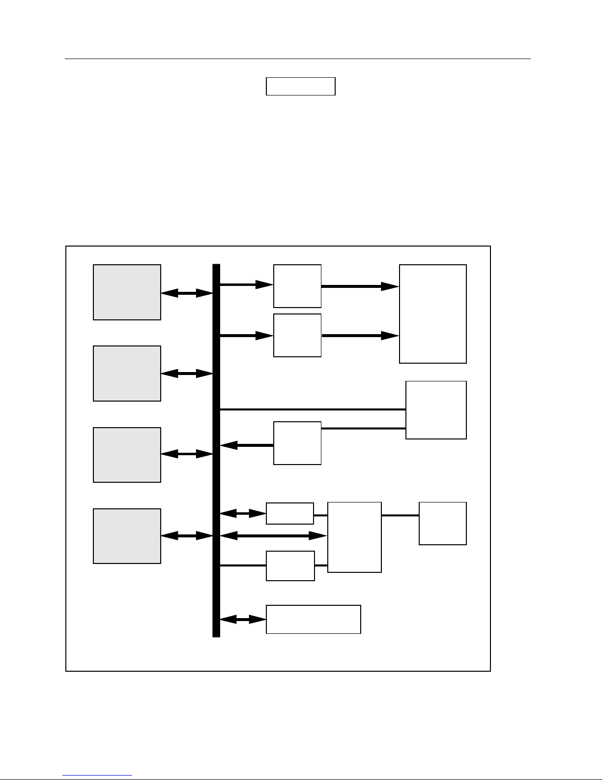
A block diagram of the circuit of the Model 190 is shown in Figure 2-1. The CMOS microprocessor is a TI
7000 series microprocessor, capable of addressing 64k bytes of memory. A 32k byte PROM contains the
operating program and an 8k byte RAM provides storage for operational and data logging information.
The microprocessor addresses the display via two display drivers. The microprocessor senses the
keypad directly, with the exception of the ON/OFF switch. The communications is direct from the
microprocessor through its ports, light emitting diodes, and photosensitive transistors. The
microprocessor reads and writes to both EEPROMs and reads count data directly from the probe adapter
module
A probe adapter module connection is provided on the back of the instrument. The probe adapter module
retains the calibration information for a specific probe and contains high voltage and threshold
adjustments for the probe. A portion of the circuit in the probe adapter module provides an adjustable
threshold for current drain through the detector. This circuit is used to detect a jam condition in the
detector and to signal the instrument. The pulse shaping circuit in the module accepts a wide range of
detector input amplitudes and pulse decay times.
Communication with the Model 190 is accomplished through an infrared two-way adapter that mounts at
the top of the instrument. The infrared receiver and transmitter are viewed through two small holes in the
upper edge of the decal covering the LCD.
2.2 Operational Considerations and Applications
Control and Configuration
The Model 190 makes use of two data bases for operation; one is stored in an EEPROM on the main
circuit board and one is stored in an EEPROM in the probe adapter module. The instrument EEPROM
determines which set of configuration and control data codes will be used to define the operating modes.
These codes may be user-modified with the optional Communicator (P/N 190-1A) to tailor the instrument
for a specific application.
For example, any or all of the front panel buttons may be disabled or the unit may be configured to
operate in only one Display Mode. Refer to the Instruction Manual provided with the Communicator for
further details.
Display Calculations
The Model 190 retains all data internally as both counts and counts per minute. All other displays are
calculated from these data sets and stored calibration information in the EEPROMS, allowing the operator
the capability to switch back and forth between the various display modes without affecting the database
used for calculations.
2-1
Page 10
Victoreen 190
Operators Manual
NOTE
The counts per minute mode does not require a
calibration adjustment because its time base is
based on the highly accurate crystal clock of the
microprocessor. All other displayed values (e.g.,
mR/h and Sv/h) can be derived from the counts per
unit time value if a suitable calibration constant is
used.
Above 384,000 CPM, the counts in a time slot are counted and the value multiplied by the appropriate
factor to determine the actual count rate, which may cause a reduced accuracy specification on the fifth
and sixth scales.
Microprocessor
PROM
RAM
EEPROM
Microprocessor I/O
and BUS
Figure 2-1. Model 190 Block Diagram
Analog
Display
Driver
Digital
Display
Driver
Front
Panel
Keypad
Counter
HV
Supply
Communicator
EEPROM
Display
Power
Supply
Probe
GM Tube
2-2
Page 11

Deadtime Effects
Theory of Operation
Operational Considerations and Applications
2
The deadtime correction is limited to a maximum multiplier of 3.7 above 106 counts per minute (cpm) 5.4
from 10
rates because of increased counting statistics. The display will indicate “OVER RANGE” if the deadtime
correction is greater than the values listed. This typically happens only on scale 6. In the event of an
overrange indication due to the deadtime, the bar graph portion of the display continues to function and
may be used to observe increased or decreased radiation even though numerical values are not
displayed. The bargraph displays relative values in this mode.
5
to 106 cpm, and 1.6 from 104 to 105 cpm. Larger correction factors are permitted at higher count
Low Battery Indications
Once every 256 seconds the instrument checks the amount of energy remaining in the batteries. When
the values reach a threshold, the instrument simultaneously displays a LOW BATTERY message and
sounds the sounder for a minimum of one second. The amount of time remaining before the unit stops
operating depends on previous use of the instrument. If the instrument is used for longer continuous
periods of time, there will be a slower decrease in available battery life at the battery end point; if the
instrument is on for shorter periods of time, the battery fails more precipitously at the battery end point.
NOTE
The display may prematurely indicate a low battery
if the count rate is high and/or the backlight and/or
Alarm are operational simultaneously.
Response Times
The response times stated in Specifications in Section 1 - Introduction apply to the bargraph display.
Since the digital data is updated only once each second, a filter is used to smooth the readings. There is
approximately two seconds additional response time (10-90% of change) for the digital display.
Range Changing
A hysteresis is built into the range changing of the Model 190 to prevent excessive range changing near a
range change threshold. In addition, internal readings above 10% of the current full scale are allowed for
one full second prior to downscaling. Any reading above the current full scale will cause a range change
to the next higher scale.
2-3
Page 12

Victoreen 190
Operators Manual
(Blank page)
Page 13

Operation
Unpacking and Inspection
Section 3
Operation
3.1 Unpacking and Inspection
Upon receipt of the unit:
1. Inspect the carton(s) and contents for damage. If damage is evident, file a claim with the carrier
and notify Fluke Biomedical, Radiation Management Services at 440.248.9300.
2. Remove the contents from the packing material.
3. Verify that all items listed on the packing list have been received and are in good condition.
If any of the listed items are missing or damaged,
notify Fluke Biomedical at 440.248.9300.
NOTE
3
3.2 Storage
If the unit is to be stored prior to use, pack it in the original container(s), if possible, and store in an
environment free of corrosive materials, fluctuations in temperature and humidity, and vibration and
shock.
3.3 Battery Installation/Replacement
Four 9-volt alkaline batteries are supplied with the Model 190. The battery compartment is located on the
back of the instrument. The compartment will hold up to four batteries. All four batteries must be in place
for proper operation and to avoid damage to the instrument. Use the following procedure to
install/replace the batteries:
To prevent battery leads from shorting on the
battery compartment’s conductive coating, Ensure
that all four batteries are INSTALLED at all times.
Unit power must be left ON and batteries replaced
one at a time to prevent data loss when the log
mode is activated and logged data is to be
retrieved.
1. Loosen the two-quarter turn fasteners securing the battery compartment cover to the back panel.
CAUTION
CAUTION
3-1
Page 14

Victoreen 190
Operators Manual
2. Remove the battery compartment cover to gain access to the batteries.
3. Replace the batteries one at a time, observing proper polarity (refer to Figure 3-1)
NOTE
The unit may make beeping sounds while inserting
the batteries.
4. Replace the battery compartment cover, securing it with the two-quarter turn fasteners.
Figure 3-1. Battery Installation (For 190AC and 190F only three 9-volt batteries are
installed.)
3.4 Probe Holder Installation
Extreme caution should be used when connecting
the probe to the meter. Improper connection may
result in injury, damage to the instrument, or
damage to the probe.
1. Attach the included Velcro strap through the strap slot in the mounting bracket.
Two Velcro straps are included. Use the strap that
fits the type of probe being utilized.
2. Attach the blade type-mounting bracket to the Model 190 Survey Meter, by performing the
following:
a. Remove and discard screw (B) from the Model 190.
b. Place the bracket in the correct position on the Model 190.
WARNING
NOTE
3-2
Page 15

CAUTION
Do not use the long screw (B), removed from the
Model 190, in screw position (A). Doing so will
damage the instrument.
c. Use the .63” screw included with the kit to secure in screw hole (A).
d. Use the 1 1/2” screw included with the kit to secure in screw hole (B).
Operation
Probe Holder Installation
3
Screw
Hole (A)
Screw (B)
MODEL
S/N REV
VICTOREEN
MADE IN U.S.A.
Figure 3-2 Probe Holder Installation
Strap
Slot
Mounting
Bracket
MODEL
S/N REV
VICTOREEN
MADE IN U.S.A.
3.5 Adapter Module Installation/Replacement
The Model 190 is shipped with a MHV compatible adapter module, (unless BNC compatibility was
requested on the purchase order). If a probe was ordered with the instrument, it is connected to the
probe adapter. Use the following procedure to replace a probe and adapter:
1. Loosen the captive Philips screw from the top panel of the adapter.
2. Unplug the probe adapter module (with detector, is applicable) from the unit.
3. Plug the replacement adapter and detector into the unit, being careful not to damage the connector
pins. It may be necessary to tilt the adapter slightly when plugging it into the unit.
3-3
Page 16

Victoreen 190
Operators Manual
NOTE
We recommend that the probe be secured to the
mating probe adapter receptacle using heat shrink
tubing.
4. Secure the Philips screw located on the top panel of the adapter.
3.6 Power
The Model 190 is powered using four 9-volt alkaline batteries. The batteries (four) are housed in a
separate compartment accessed from the instrument back panel. All four
required to operate the unit for approximately 200 hours. Visual and audible low battery indications are
provided whenever battery power is low (four minute intervals for the audible and continuous for the visual
after a battery test).
9-volt alkaline batteries are
3.7 Readout
Measurement results are indicated on the front panel LCD. The display includes an analog bargraph,
scale multiplier, detector range bargraph, and a 16 character alphanumeric display (refer to Figure 3-3).
Each of the 51 elements in the bargraph represents 2% of the scale span. The analog bar graph is
divided into 5 sections with scale notations of 0, 2, 4, 6, 8, and 10. The scale sections are marked by
longer bars. The bars are arranged in an arc with a radius of 3.75 inches (9.5 cm.). Scale length is 2
inches (5 cm.).
The 51 element analog bargraph, located near the top of the display, provides real time response. It is
designed to emulate an analog meter movement, making it especially useful in survey applications. The
16 character alphanumeric display at the bottom of the LCD displays units, an average digitized value of
the reading, error messages, integrated value (with elapsed time), operational parameters (e.g., response
time), low battery indication, probe type and serial number, and data logging information.
A scale multiplier, located below the bargraph relates the analog bargraph full scale to the units displayed.
The detector range bargraph consists of five horizontal bars that indicate the decade of the dynamic
range in cpm of the detector in use. Most detectors will cover a dynamic counting range of five decades.
A few detectors (e.g., those with short dead times) can reach the sixth decade of operation. The sixth
decade is indicated by all five bars being lit.
NOTE
The bargraph may be disabled using the Model
190-1A Communicator.
In the Alarm condition, the entire display blinks on and off with a period of two seconds
3-4
Page 17

3.8 Internal Controls
Operation
Internal Controls
3
CAUTION
Use extreme care and ensure that you are properly
grounded prior to opening the unit for voltage
adjustments. Failure to comply could destroy the
instrument.
Display Contrast Adjustment (RP1)
The Model 190 display is designed for optimum viewing at approximately 60o from the plane of the display
and directed toward the bottom of the instrument. The Display Contrast Adjustment (RP1) is factory set
for optimum viewing and Fluke Biomedical does not recommend that it be further adjusted. However; if
the display contrast requires adjustment, turn RP1 to vary the angle of maximum contrast of the 16character display. The contrast for the upper part of the display is fixed. Refer to Figure 3-4 for RP1
location.
Voltage Adjustment (RP2)
A +5 volt adjustment is provided on the main circuit board. Refer to Figure 3-3 for adjustment location.
Use the following procedure:
1. Connect the - lead of a DVM to the groundside of R18.
2. Connect the + lead of the DVM to Z10-12.
3. Adjust RP2 for 5.00 volts +
0.02 volts.
46
2
0
8
10
X0.0.0.010 MILLION
X0.100 THOUSAND
Figure 3-3. Model 190 Display
3-5
Page 18

Victoreen 190
Operators Manual
Display Contrast Adjustment (RP1)
+5 V Adjustment (RP2)
Figure 3-4. Display Contrast (RP1) and +5 (RP2) Adjustment Locations
Probe Adapter Module Adjustments
The probe adapter module has high voltage (RP3), detector sensitivity (RP2), and detector jam current
(RP1) adjustments located within it. Use the following procedure to make the appropriate adjustments:
1. Loosen the Philips screw on the top panel of the adapter.
2. Unplug the adapter from the unit.
3. Remove the flat head screw from the bottom panel of the adapter.
4. Remove the top panel of the adapter to gain access to the inner components.
There is a potential shock hazard when the adapter
cover is removed and the unit is operating. Use an
insulated screwdriver when making adjustments,
being careful not to touch any of the components
5. Plug the adapter back into the Model 190 with the component side of the circuit board exposed.
3-6
other than the potentiometers specified.
CAUTION
Page 19

Operation
Internal Controls
NOTE
It may be necessary to tilt the adapter slightly when
6. Make the required voltage, threshold, and jam current adjustments as outlined in the following
paragraphs.
attempting to plug it into the unit.
NOTE
The Model 190 must be turned ON while making
7. When the adjustments are completed, unplug the adapter from the unit.
8. Position the back panel on the adapter.
9. Replace the flat head screw removed in step 3.
10. Plug the adapter back into the unit.
11. Secure adapter to unit by tightening the captive screws located on the top panel of the adapter.
the probe adapter adjustments.
3.9 HIGH VOLTAGE ADJUSTMENT
3
NOTE
Determine which module you have (surface mount
or non-surface mount) before continuing, and
Refer to Figure 3-5 for location of the high voltage adjustment (RP3). Use the following procedure to
adjust the detector high voltage:
1. Turn unit power OFF.
2. Locate the 3-pin jumper connector JP1 (refer to Figure 3-5 for jumper location).
3. Position the jumper as required for either a surface mount or non-surface mount module by
referring to Figure 3-6.
4. Connect either a DVM with a high resistance probe (> 100Mohm) or an electrostatic voltmeter to
the MHV or BNC connector.
5. Turn the Model 190 on.
6. Adjust RP3 for the required voltage.
ensure that the correct figure is referenced.
3-7
Page 20

Victoreen 190
Operators Manual
Figure 3-5. Probe Adapter Adjustments
3-8
Page 21

High Voltage Adjustment
Figure 3-6. High Voltage Jumper Positioning
3.10 DETECTOR SENSITIVITY ADJUSTMENT
Operation
3
Refer to Figure 3-5 for location of the detector sensitivity adjustment (RP2). The adjustment is factory set
to 80 mV. If necessary, use a variable amplitude pulse fail generator and turn RP2 counterclockwise to
increase sensitivity.
3.11 JAM CURRENT ADJUSTMENT
Refer to Figure 3-5 for location of the jam current adjustment (RP1). Use the following procedure to
adjust the jam current:
1. Adjust RP1 fully counter-clockwise.
2. Bring the detector to a high-count rate until the reading begins to drop with increasing intensity.
3. Adjust RP1 clockwise until the jam message appears on the display.
NOTE
An overrange message may occur during this
adjustment, indicating that the probe has reached
the limit of its deadtime correction; in this case, the
jam message may be set to appear above
overrange.
3.12 Changing the Response Time (Resp Time)
The Model 190 response time may be changed by pressing the front panel Resp Time push-button.
When Resp Time is pressed, the next response time will be selected and the following will appear on the
alphanumeric display:
RESPONSE IS XX S
3-9
Page 22

Victoreen 190
Operators Manual
XX is 24, 12, 6, or 3 seconds, corresponding to the newly selected response time.
The Resp Time button may be pressed as necessary to scroll through and select the desired response
time. The Resp Time button may be disabled via the Model 190-1A Communicator.
NOTE
The response time displayed is for the lowest
range. Refer to Specifications in Section 1 General Information for corresponding response
times on other ranges.
3.13 Resetting the Integrate Value (Resp Time)
If the instrument is in the Integrate Mode and the reset integrator is enabled via the optional Model 1901A Communicator, the integrate value may be reset by pressing and holding the Resp Time button for
three seconds. The integrate values will reset to zero; the response time will not change. The integrate
reset function may be disabled via the Model 190-1A Communicator.
3.14 Changing the Operation Mode (Mode)
The Model 190 factory default Operational Mode is C/MIN. Using the optional Model 190-1A Infra-red
communicator, default settings can be changed/programmed into the Model 190. Features and push
buttons can also be locked-out to set up the Model 190 in a user-defined mode of operation. The
Operational Mode may be changed by pressing the front panel Mode push-button. The next available
mode will then be displayed corresponding to the newly selected Mode. The Mode button may be
pressed as necessary to scroll through and select the desired Mode, and includes the following:
1. COUNTS/MIN MODE
2. COUNTS/SEC MODE
3. mR/H MODE
2
4. Bq/cm
5. μCi/cm
6. DPM MODE
4. Sv/H MODE
5. Gy/H MODE
MODE
2
MODE
NOTE
If the probe has not been initialized and calibrated
(either at the factory or via the operational infrared
communicator), the CPM and CPS modes are the
only modes available. Also, the mCi/sqcm,
Bq/sqcm, and dpm modes require an additional
special calibration performed with the probe. Refer
to section 5 - Calibration for further details.
3-10
Page 23

Operation
Changing the Operation Mode (Mode)
All but one of the Operational Modes may be disabled via the Model 190-1A Communicator; one default
mode must be enabled for the instrument to operate properly.
Changing the Display Mode (Rate/Integ)
The front panel Rate/Integ button toggles the alphanumeric display between the digitized rate value and
the integrate value. Press Rate/Integ to automatically change the display mode.
The Rate/Integ button may be disabled (and the display mode fixed) via the optional Model 190-1A
Communicator.
Logging Displayed Data (Log)
If the Data logging function is selected to be operational (via the optional Communicator), currently
displayed data will be stored for future retrieval. The procedure for logging data depends on the Log
Mode (Manual or Timed, with or without location identifiers, as selected via the communicator).
The Log Mode is always inactive when the unit is
turned on and data logging can only be activated
through the optional Communicator. If the Log
Mode has not been activated, a NOT IN LOG
MODE message will be displayed when the Log
button is pressed. When in the data logging mode,
the instrument ON/OFF button is in active and the
instrument will stay on until the data has been
retrieved. Refer to the Instruction Manual provided
with the communicator for further information and
instructions.
In the manual mode, displayed data is logged by pressing the front panel Log button. The following
message will appear in the alphanumeric display:
NOTE
3
Data logging in manual mode. ready
In the timed mode, data is logged at specific intervals. The following message will appear in the
alphanumeric display:
Data logging in timed mode. ready
Remote Communication (Optional)
Communication with the Model 190I and Model 190 is accomplished via the Model 190I-1A
Communicator that plugs into top of the instrument.
NOTE
For remote communication, use the Model 1901A Communicator and the 94190C00 software
provided.
For additional information and operation of
remote communications, refer to the 190003
instruction manual provided with the Model 1901A.
3-11
Page 24

Victoreen 190
Operators Manual
3.15 External Controls
The Model 190 has eight external front panel push-button controls. The front panel controls include four
functional buttons and four operational buttons. The functional buttons include including Mode, Log,
Rate/Integ, and Resp Time, effect the daily operation of the unit.
The four operational push buttons and their functions are:
Light (2) activates the LCD backlight.
Audio toggles the click output on/off and acknowledges an alarm condition.
The click output is associated with counting events
in the detector
On/Off toggles instrument power on/off when allowed by the microprocessor.
The four functional push buttons are as follows:
Mode changes the display units.
Log, when pushed momentarily, logs currently displayed data or changes current location identifier,
depending on the currently active logging mode; when pressed and held for three seconds, and a
logging with locations mode is active, Log changes the label.
Rate/Integ toggles the alphanumeric display between the digitized rate value and the integrate
value.
Resp Time changes the response time on the first range or resets the integrate value and time.
NOTE
3.16 Operational Checkout
1. Install the batteries as outlined earlier in this Section (Battery Installation/Replacement).
2. Install the probe holder kit as outlined earlier in this Section (Probe Holder Kit Installation).
3. Install the probe and adapter as outlined earlier in this Section (Probe and Adapter Installation).
4. Turn the instrument on by pressing the ON/OFF button on the front panel.
5. Observe the following:
a. All segments of the display should come on for approximately one second.
If the display does not come on at all, replace the
batteries and try again. If a partial display is visible,
contact Fluke Biomedical at 440.248.9300 for
b. The display will blank and display the version number of the software in the alphanumeric
display.
c. The unit will read the internal and external EEPROMs and display the Probe Model Number
and Serial Number, or a portion of it.
further instructions.
NOTE
3-12
Page 25

Operation
Operational Checkout
NOTE
In the event that the internal and external
EEPROMS were not properly read, an error
message(s) will be displayed (i.e., “INT EEPROM
FAIL” and/or “EXT EEPROM FAIL”). Contact Fluke
Biomedical at 440.248.9300 for further instructions.
d. The instrument will then begin to operate in the selected mode.
NOTE
The instrument is factory set with all buttons
operational and the CPM and mR/H modes
selected. (The Log Mode is inactive.)
6. Test each button of the instrument, as follows:
a. Press each LIGHT button to cause the display backlight to turn on. (The backlight may not
show up in a bright environment.)
b. Press the MODE button to toggle the available display modes that were enabled during
calibration. The current mode will be displayed briefly on the 16-character alphanumeric
display. An example:
- COUNTS/MIN MODE
- COUNTS/SEC MODE
- mR/H MODE
NOTE
If the probe has not been initialized and calibrated
(either at the factory or via the optional infrared
communicator), the CPM and CPS modes are the
only modes available. In addition, the mCi/sqcm,
Bq/sqcm, and dpm modes require an additional
special calibration performed with the probe. Refer
to section 5 - Calibration for further details.
c. Press the LOG button to log displayed data. If the Log Mode has been activated, the following
should appear in the alphanumeric display:
LOGGING DATA
If the Log Mode has not been activated, the following message will be displayed:
NOT IN LOG MODE
The Log Mode can only be activated using the optional Communicator, Model 190-1A. Refer to the
Instruction Manual supplied with the Communicator for details.
d. Press the RATE/INTEG button to toggle the alphanumeric display between the Rate Mode
and the Integrate Mode.
e. Press the RESP TIME button to toggle the available response time selections. The new
selection is displayed in the alphanumeric display as follows:
RESPONSE IS XX S
where XX is the currently active first scale response time.
3
3-13
Page 26

Victoreen 190
Operators Manual
NOTE
If the instrument is in the Integrate Mode, press and
hold the RESP TIME button for three seconds. The
integrate values should reset to zero without
changing the response time.
f. Press the AUDIO button to toggle on or off the click from the speaker associated with each
count from the detector. The clicks from the speaker have a one to one correspondence with
counts from the detector up to 3200 cpm. For counts above 3200 cpm, there is a transition
from clicks to a steady tone.
g. Press the ON/OFF button to turn the instrument off.
NOTE
If the instrument is in the Log Mode, the unit can be
turned OFF only after all logged data has been
read from the internal RAM using the
communications software. Refer to the Instruction
Manual provided with the Model 190-1A
Communicator for further details.
3-14
Page 27

Maintenance
Maintenance
Section 4
Maintenance
4.1 Maintenance
Fluke Biomedical recommends the following maintenance and troubleshooting procedures for the Model
190:
NOTE
Table 4-1 lists recommended spare parts.
Schematics, assembly drawings, and complete
parts lists are provided in Appendix A.
1. Battery replacement as outlined in Section 3 - “Operation” when LOW BATTERY appears in the
alphanumeric display and/or the audio low battery indication is activated.
NOTE
If the LOW BATTERY message remains displayed
after replacing the batteries, check the detector
high voltage (RP3) as outlined in Section 3 “Operation”. If the message is still displayed,
contact Fluke Biomedical at 440.248.9300 for
further instructions.
2. If a problem occurs with the printed circuit board, case, or audible alarm transducer, the suspect
part is easily replaceable. Refer to Table 4-1 for a list of Replacement parts.
a. The printed circuit board has all but the PROM, RAM, and the microprocessor soldered into the
board.
b. The case and modules are molded plastic and may require replacement due to contamination.
c. The speaker and its gasket are open to the surface of the instrument, to allow audible
indications to be clearly heard, and may therefore require replacement due to contamination.
3. If the problem is isolated to the probe or module, refer to Section 3 - Operation for replacement
procedures.
4. If the problem cannot be isolated or corrected using the above procedures, contact Fluke
Biomedical at 440.248.9300 for further instructions.
4
4-1
Page 28

Victoreen 190
Operators Manual
Table 4-1. Recommended Spare Parts
Part No. Description
190010SM Main Circuit Board Assembly
190021 Case Top
190026A Display Window Decal
190027 Membrane Switch Decal
190033 Battery Plate
91-11-1 1/4 Turn Fastener (2)
190031 Case Bottom
190023 Battery Cover
190035 Battery Cover Gasket
149036 Transducer Screen
67-115 Connector
190015 Keypad Assembly
5-1154 Phillips Screw (5) 6-19 X 1.25 PH
5-1153 Phillips Screw 6-19 X 0.50 FH
5-1151
5-1152 Screw (2) Battery Plate 6-20 X .31 Hex HD
91-11-2 Retainer for 1/4 Turn Fastener (2)
190001K Probe Holder Kit
190213 Bracket
190235 Stand
190007 Battery Cable Assembly (2)
PC Board Assembly Screw (3) 4-24 X .25
Hex HD
4-2
Page 29

Calibration
Calibration
Section 5
Calibration
5.1 Calibration
The probe adapter modules carry the calibration data for the instrument. If the unit is shipped with a
probe, the module is calibrated at the factory prior to shipment; otherwise, the module is shipped
uncalibrated. The instrument itself does not require calibration.
If required, calibration data stored in the probe adapter may be changed using the optional
Communicator, P/N 190-1A. Refer to the instruction manual supplied with the Communicator for further
instructions and specific procedures for entering calibration data.
5
Avoid indiscriminately mating probes with an
adapter module; otherwise damage to the
instrument or probe or loss of stored calibration
factors, parameters, and other operational
information may occur. Fluke Biomedical
recommends the use of heat shrink tubing to
permanently connect the probe and adapter.
CAUTION
5-1
Page 30

Victoreen 190
Operators Manual
(Blank page)
Page 31

Appendix
Applicable Drawings and Bills of Materials
Appendix A
Applicable Drawings and Bills of Materials
A.1 Applicable Drawings and Bills of Material
The following drawings and Bill of Materials are applicable to the Model 190 and contain proprietary
information. If you require these drawings, please contact Fluke Biomedical at 440.248.9300.
Drawings
Drawing Number Description
190013SM Model 190 Schematic
191005 Model 190 Assembly
190010SM Main Circuit Board Assembly
Bills of Material
Document Number
191005 Bill of Materials, Model 190 Assembly
190010SM Bill of Materials, Main Circuit Board Assembly
Description
A
A-1
Page 32

Victoreen 190
Operators Manual
(Blank page)
Page 33

Appendix
Supplemental Data for the Model 190AC & 190F
B
Appendix B
Supplemental Data for the Model 190AC & 190F
B.1 Supplemental Data for the Model 190AC & 190F
Product Description
The Model 190F is a Model 190AC with a metal stand and an AC to 9 VDC power adapter module. The
Model 190AC can be powered internally from three 9-volt DC batteries, or externally from AC through a
power adapter module.
Specifications
The Model 190AC has all the features of a standard Model 190 plus the ability to be powered from AC via
an appropriate power adapter, and a metal stand to hold the survey meter at a 60 degree angle for ease
of viewing.
The metal stand is rugged, being made of formed and welded steel. The Model 190AC can be easily
inserted and removed from this stand.
Dimensions:
The dimensions of the Model 190AC are the same as the Model 190. Refer to the specifications in
Section 1.
The dimensions of the metal stand are: (W X H X D) 4" x 9.5" x 4.75" (10.2 X 24.3 X 12 cm).
Miscellaneous:
AC to DC Adapter Line Cord Length: 6 feet
Weight:
4.1 lbs. total (Model 190 + AC to DC adapter + metal stand) (1.86 kg)
Power Requirements:
Internal: Three 9-volt batteries
To prevent battery leads from shorting on the
battery compartment’s conductive coating, ensure
that all three batteries are INSTALLED at all times,
even when using the adapter as power supply.
CAUTION
AC Power Converter
Part 14-409 (United States)
Input 120 VAC, 60 Hz, 13W
Output 9 VDC, 500 mA, Regulated
B-1
Page 34

Victoreen 190
Operators Manual
Part 14-434 (Europe)
Input 230 VAC, 50 Hz, 84 mA, 18.6 VA
Output 9 VDC, 780 mA, 7.02 VA, Regulated
Part 14-435 (United Kingdom)
• Input 230 VAC, 50 Hz, 19.1 VA
• Output 9 VDC, 780 mA, Regulated
Part 14-435, Part 14-416 (Australia)
Battery Lifetime
When powered from AC: Shelf life of the batteries
When powered from the batteries: minimum of 100 hours
Installation
Plug the 9-volt jack into the back of the Model 190AC and the AC to 9-volt DC adapter module into the AC
outlet. Turn on the Model 190AC. Doing this in any other order will not damage the Model 190AC or the
AC to DC converter module.
Removing the 9-volt DC power jack while the unit is on and powered from this source will not damage the
190AC or the adapter module.
The metal stand has holes in the base and back to permit permanent installation if desired.
Operational Procedure
The Model 190AC may be inserted or removed from the metal stand at any time.
There is no change in operational procedures from the Model 190. The Model 190AC will operate with
the AC to 9 VDC adapter module installed and no 9-volt batteries.
Applications
Possible applications for the 190F are:
Any environment where AC voltage is present and a survey meter is expected to be set up for active
operation and ease of viewing on a fairly continuous basis.
Frisker stations
Portable Portal Monitors
Troubleshooting
Refer to Section 4 - Maintenance for troubleshooting procedures.
Service Information
General
The 190F contains three functional elements:
Model 190AC Survey Meter
AC to 9-volt DC Adapter Module
Metal Stand
B-2
Page 35

Appendix
Supplemental Data for the Model 190AC & 190F
Circuit Description
Refer to the 190 and Model 190AC sections.
Calibration and Adjustments
For calibration and adjustments to the Model 190AC, refer to the Model 190 and 190AC sections of this
manual.
Replacement Parts
Item Part Number
Model 190AC 190AC
Metal Stand 190232
Ac to Dc Adapter Module 14-409 (120 VAC), United States
14-434 (230 VAC), Europe
14-435 (230 VAC), United Kingdom
14-435 & 14-416, Australia
190 Manual 190001
B
B-3
Page 36

Victoreen 190
Operators Manual
(Blank page)
Page 37

Appendix
Adapter Bracket Assembly Kit Installation Instructions
Appendix C
Adapter Bracket Assembly Kit Installation Instructions
C.1 Adapter Bracket Assembly Kit Installation Instructions
You are not required to mount the adapter bracket
assembly to the adapter stand. If you choose to
mount the adapter bracket assembly to the adapter
stand, please perform the following;
1. Remove the adapter bracket assembly kit from the plastic bag.
2. Ensure the following are included:
Item
Adapter bracket assembly (190235) 1
#6-32 Machine Screws 3
#6 Split Washers 3
# 6-32 Hex Nuts 3
3. Align the three holes on the side of the adapter bracket assembly (190235) with the three holes on
4. Mount the adapter bracket assembly to the adapter stand using the three sets of machine screws,
5. The frisker probe can be placed in the adapter bracket assembly clip.
6. Tension on the clip can be adjusted by widening or squeezing close the spring clip opening.
This completes the assembly instructions.
Qty
the right side of the adapter stand (190213).
washers, and nuts. Be sure to place the hex nuts on the inside of the stand. Hand tighten the
screws using a screwdriver.
NOTE
C
C-1
Page 38

Fluke Biomedical
Radiation Management Services
6045 Cochran Road
Cleveland, Ohio 44139
440.498.2564
120 Andrews Road
Hicksville, New York 11801
516.870.0100
www.flukebiomedical.com/rms
 Loading...