

Fluke Versiv User Manual

™
Versiv
Cabling Certification
Product Family
Users Manual
April 2014, Rev. 3 8/2015
©2014-2015 Fluke Corporation
All product names are trademarks of their respective companies.

LIMITED WARRANTY AND LIMITATION OF LIABILITY
Each Fluke Networks product is warranted to be free from defects in material and
workmanship under normal use and service unless stated otherwise herein. The
warranty period for the mainframe is one year and begins on the date of purchase.
Parts, accessories, product repairs and services are warranted for 90 days, unless
otherwise stated. Ni-Cad, Ni-MH and Li-Ion batteries, cables or other peripherals are all
considered parts or accessories. The warranty extends only to the original buyer or end
user customer of a Fluke Networks authorized reseller, and does not apply to any
product which, in Fluke Networks’ opinion, has been misused, abused, altered,
neglected, contaminated, or damaged by accident or abnormal conditions of
operation or handling. Fluke Networks warrants that software will operate
substantially in accordance with its functional specifications for 90 days and that it has
been properly recorded on non-defective media. Fluke Networks does not warrant
that software will be error free or operate without interruption.
Fluke Networks authorized resellers shall extend this warranty on new and unused
products to end-user customers only but have no authority to extend a greater or
different warranty on behalf of Fluke Networks. Warranty support is available only if
product is purchased through a Fluke Networks authorized sales outlet or Buyer has
paid the applicable international price. To the extent permitted by law, Fluke
Networks reserves the right to invoice Buyer for repair/replacement when a product
purchased in one country is submitted for repair in another country.
For a list of authorized resellers, visit
Fluke Networks warranty obligation is limited, at Fluke Networks option, to refund of
the purchase price, free of charge repair, or replacement of a defective product which
is returned to a Fluke Networks authorized service center within the warranty period.
To obtain warranty service, contact your nearest Fluke Networks authorized service
center to obtain return authorization information, then send the product to that
service center, with a description of the difficulty, postage and insurance prepaid (FOB
destination). Fluke Networks assumes no risk for damage in transit. Following
warranty repair, the product will be returned to Buyer, transportation prepaid (FOB
destination). If Fluke Networks determines that failure was caused by neglect, misuse,
contamination, alteration, accident or abnormal condition of operation or handling,
or normal wear and tear of mechanical components, Fluke Networks will provide an
estimate of repair costs and obtain authorization before commencing the work.
Following repair, the product will be returned to the Buyer transportation prepaid and
the Buyer will be billed for the repair and return transportation charges (FOB Shipping
point).
THIS WARRANTY IS BUYER’S SOLE AND EXCLUSIVE REMEDY AND IS IN LIEU OF ALL
OTHER WARRANTIES, EXPRESS OR IMPLIED, INCLUDING BUT NOT LIMITED TO ANY
IMPLIED WARRANTY OF MERCHANTABILITY OR FITNESS FOR A PARTICULAR PURPOSE.
FLUKE NETWORKS SHALL NOT BE LIABLE FOR ANY SPECIAL, INDIRECT, INCIDENTAL OR
CONSEQUENTIAL DAMAGES OR LOSSES, INCLUDING LOSS OF DATA, ARISING FROM
ANY CAUSE OR THEORY.
Since some countries or states do not allow limitation of the term of an implied
warranty, or exclusion or limitation of incidental or consequential damages, the
limitations and exclusions of this warranty may not apply to every buyer. If any
provision of this Warranty is held invalid or unenforceable by a court or other decisionmaker of competent jurisdiction, such holding will not affect the validity or
enforceability of any other provision.
www.flukenetworks.com/wheretobuy.
4/15
Fluke Networks
PO Box 777
Everett, WA 98206-0777
USA

Chapter 1 Get Acquainted
Overview of Features ......................................................1
Contact Fluke Networks .................................................2
Register Your Product ....................................................2
Technical Reference Handbook .....................................3
Additional Resources ......................................................3
Supplements and Updated Manuals .............................3
Kit Contents ....................................................................3
Certifications and Compliance .......................................4
Safety Information ...................................................5
For the Versiv Main Unit ..........................................5
For DSX Modules ......................................................7
For CertiFiber Pro OLTS Modules .............................8
For OptiFiber Pro OTDR Modules ............................10
AC Adapter and Battery .................................................11
Charge the Battery ...................................................11
Check the Battery Status ..........................................12
Verify Operation .............................................................14
How to Use the Touchscreen .........................................15
Change the Language ....................................................17
Buttons to Do Tests and Save Results ............................17
Overview of Memory Functions .....................................19
Options for Cable IDs ......................................................20
How to Install a Strap .....................................................21
How to Remove or Install a Module ..............................21
Contents
i

Versiv Cabling Certification Product Family
Users Manual
About LinkWare Applications ....................................... 23
LinkWare PC Cable Test Management Software ... 23
The LinkWare Live Web Application ...................... 23
LinkWare Stats ......................................................... 23
Chapter 2 Certify Twisted Pair Cabling
Overview of Features ..................................................... 25
Connectors, Keys, and LEDs ........................................... 26
About Link Interface Adapters ...................................... 30
About the DSX-PLA001 Adapter Modules .................... 32
The DSX CableAnalyzer Home Screen .......................... 34
Make Sure Your Tester is Ready to Certify Cabling ..... 36
Set the Reference ........................................................... 37
Settings for Twisted Pair Tests ....................................... 38
How to Do an Autotest .................................................. 43
“Bad Patch Cord” Message ............................................ 46
How to Certify Patch Cords ........................................... 47
Twisted Pair Autotest Results ........................................ 47
Automatic Diagnostics ............................................. 48
PASS*/FAIL* Results ................................................. 49
WIRE MAP Tab ......................................................... 50
PERFORMANCE Tab ................................................. 52
Frequency-Domain Results ...................................... 53
How to Save Frequency-Domain Results
as a Plot or a Table ............................................ 53
DIAGNOSTIC Tab ...................................................... 58
Continuous Tests ...................................................... 58
About the AxTalk Analyzer Kit ..................................... 58
ii

Chapter 3 Certify Coaxial Cabling
Set the Reference for Coaxial Tests ...............................59
Settings for Coaxial Tests ...............................................61
How to Do an Autotest ..................................................63
Coaxial Autotest Results .................................................66
About Splitters ................................................................67
Tests Without a Remote .................................................68
Continuous Tests .............................................................71
Chapter 4 Clean Fiber Endfaces
Always Clean Endfaces Before Tests ..............................73
How to Use a Fluke Networks IBC OneClick Cleaner ....76
How to Use Wipes, Swabs, and Solvent ........................78
To Clean Bulkhead Connectors ................................78
To Clean the Optical Connectors on the Modules .79
To Clean Fiber Adapters ..........................................79
To Clean Connector Ends .........................................79
Contents
Chapter 5 Inspect Fiber Endfaces
Connectors, Keys, and LEDs ............................................82
Settings for FiberInspector Tests ....................................84
How to Do the FiberInspector Test ................................85
Automatic Analysis of Scratches and Defects ...............90
Fiber Tests with Two Main Testers .................................92
Chapter 6 Certify Fiber Cabling
Overview of Features ......................................................93
Connectors, Keys, and LEDs ............................................94
How to Remove and Install the Connector Adapters ...98
The CertiFiber Pro Home Screen ....................................100
iii

Versiv Cabling Certification Product Family
Users Manual
Requirements for Reliable Fiber Test Results ............... 102
About the Reference for Fiber Tests ....................... 103
When to Set the Reference .............................. 103
Good Reference Values ..................................... 104
How to See the Reference Values ....................105
About Test Reference Cords and Mandrels ............ 105
About the EF-TRC (Encircled-Flux
Test Reference Cords) ....................................... 106
About APC Connectors ...................................... 108
About Standard Mandrels ................................ 110
Settings for Fiber Tests ................................................... 110
About 1 Jumper Reference Connections ...................... 117
Autotest in Smart Remote Mode .................................. 118
Fiber Tests with Two Main Testers .......................... 118
Step 1: Set the Reference in Smart Remote Mode 120
Step 2: Measure the Loss of the Test
Reference Cord You Will Add ................................. 122
Step 3: Do an Autotest in Smart Remote Mode .... 123
Autotest Results for Smart Remote Mode ............. 124
Fiber IDs for Saved Results in Smart Remote Mode 124
Autotest in Loopback Mode .......................................... 126
Step 1: Set the Reference in Loopback Mode ........ 128
Step 2: Measure the Loss of the Test Reference
Cord You Will Add ................................................... 130
Step 3: Do an Autotest in Loopback Mode ............ 131
Autotest Results for Loopback Mode ..................... 132
Autotest in Far End Source Mode ................................. 134
Auto Wavelength Modes ........................................ 134
Step 1: Set the Reference in Far End Source Mode 136
iv

Step 2: Measure the Loss of the Test Reference
Cord You Will Add ...................................................139
Step 3: Do an Autotest in Far End Source Mode ....140
Autotest Results for Far End Source Mode .............141
Bi-Directional Tests .........................................................143
Chapter 7 Use the OTDR
Overview of Features ......................................................145
Connectors, Keys, and LEDs ............................................146
How to Remove and Install the Connector Adapters ...148
The OptiFiber Pro Home Screen .....................................150
Settings for OTDR Tests ..................................................152
About Launch and Tail Cords .........................................156
How to Prevent Damage to the
Launch Cord Connectors ..........................................158
How to Hang the Launch Cords ..............................158
OTDR Port Connection Quality ......................................159
How to Do an OTDR Test ...............................................161
OTDR Results ...................................................................165
EventMap ..................................................................165
Event Table ...............................................................169
OTDR Trace ...............................................................172
The FaultMap Test ..........................................................174
How to Do the FaultMap Test .................................175
FaultMap Screen .......................................................178
The SmartLoop Test ........................................................180
How To Do an Auto SmartLoop Test ......................181
SmartLoop Results ....................................................184
Bi-Directional SmartLoop Tests ................................185
Contents
v

Versiv Cabling Certification Product Family
Users Manual
Chapter 8 Use the Visual Fault Locator
Visual Fault Locator Applications .................................. 189
How to Use the VFL ........................................................ 190
Chapter 9 Monitor Optical Power
How to Monitor Power and Loss ................................... 193
How to Control the Light Source .................................. 197
Use the Display to Control the Main
Tester’s Light Source ................................................ 198
Use the Module’s Button to Control the
Light Source ............................................................. 198
Chapter 10 Manage Test Results
View Saved Results ......................................................... 201
How to Add a Result to a Saved Result ........................ 204
How to Replace a Saved Result that Failed .................. 205
Delete, Rename, and Move Results ............................... 206
Manage Results on a Flash Drive ................................... 207
Upload Results to a PC ................................................... 208
View the Memory Status ............................................... 210
Chapter 11 Use Projects
Why Use Projects? .......................................................... 211
Set Up a Project .............................................................. 212
The PROJECT Screen ....................................................... 212
The CABLE ID SETUP Screen ........................................... 215
About Next ID Sets ......................................................... 215
Manage Projects on a Flash Drive ................................. 218
Copy Project Settings to Other Testers ......................... 219
vi

Chapter 12 Sync Projects with LinkWare™ Live
Sign Up for a LinkWare Live Account ............................221
How to See the Tester’s MAC Address ..........................222
Use LinkWare Live Through a Wired
Ethernet Network ...........................................................222
Use LinkWare Live Through a Wi-Fi
Ethernet Network ...........................................................223
Change the Network Settings ........................................226
Settings for the Wired Port .....................................226
Settings for the Wi-Fi Port .......................................226
Sign Your Tester Out of LinkWare Live .........................226
Get Started with LinkWare Live .....................................228
Sign In to LinkWare Live from a Desktop
or Mobile Device .............................................................228
Import Projects from LinkWare Live into
LinkWare PC ....................................................................229
Chapter 13 Maintenance
Verify Operation .............................................................232
Clean the Tester ..............................................................232
Clean the FI-1000 Video Probe .......................................232
Traceable Calibration Period ..........................................233
See Information About the Tester .................................233
Update the Software ......................................................233
Use a PC to Update the Software ............................234
Use an Updated Main Tester to Update
Other Testers ............................................................236
Use LinkWare Live to Update the Software ...........236
Update the Software in a Module ..........................237
Extend the Life of the Battery .......................................237
Contents
vii

Versiv Cabling Certification Product Family
Users Manual
Store the Tester .............................................................. 237
Remove the Battery ....................................................... 239
Calibration ...................................................................... 239
If the Tester Does Not Operate as Usual ....................... 240
Options and Accessories ................................................ 241
Regulatory Information ................................................. 241
Appendix A: Reference Method Names
Appendix B: Modified 1 Jumper Reference Method
viii

List of Figures
Figure Page
1. LEDs Show the Remote’s Battery Status........................ 13
2. Connections to See the Status of a Remote’s Battery .. 14
3. How to Zoom the Screen................................................ 16
4. FIX LATER, TEST AGAIN, and TEST Buttons and
the TEST Key.................................................................... 17
5. How to Install a Strap and Use the Hand Strap ............ 21
6. How to Remove and Install a Module ........................... 22
7. Main Tester Connectors, Keys, and LEDs....................... 26
8. Remote Tester Connectors, Keys, and LEDs .................. 28
9. How to Attach and Remove Link Interface Adapters... 30
10. How to Prevent Damage to the Permanent
Link Adapter Cables........................................................ 31
11. How to Change the Personality Module
on a DSX-PLA001 Adapter.............................................. 33
12. The Home Screen for the DSX CableAnalyzer .............. 34
13. Reference Connections for Twisted Pair Cable ............. 38
14. Outlet Configurations .................................................... 42
15. Equipment for Autotests on Twisted Pair Cable........... 43
16. Permanent Link Connections ......................................... 45
17. Channel Connections ...................................................... 46
18. Examples of Diagnostic Screens for
Faults on Twisted Pair..................................................... 49
19. PASS* and FAIL* Results ................................................. 50
20. WIRE MAP Tab ................................................................ 51
21. PERFORMANCE Tab ........................................................ 52
ix

Versiv Cabling Certification Product Family
Users Manual
22. Tabular Results Screen for a Frequency-Domain Test ...54
23. Plot Screen for a Frequency-Domain Test ......................56
24. Reference Connections for Tests on Coaxial Cabling ....60
25. Equipment for Tests on Coaxial Cabling ........................64
26. Examples of Connections for Tests on Coaxial Cabling.65
27. Autotest Results for Coaxial Cabling ..............................66
28. Connections for Coaxial Tests Without a Remote .........70
29. Examples of Clean and Dirty Fiber Endfaces..................73
30. Equipment to Clean and Inspect Fiber Endfaces ...........75
31. How to Use the IBC OneClick Cleaner ............................77
32. Connectors, Keys, and LEDs ............................................82
33. Equipment for the FiberInspector Test ..........................85
34. How to Use the FI-1000 Probe ........................................87
35. How to Use the Optional MPO/MTP
®
Inspection Tip.....87
36. FiberInspector Image with Manual Grading Selected...88
37. FiberInspector Image with Defect Analysis ....................91
38. Main Tester Connectors, Keys, and LEDs
(CFP-QUAD module shown) ............................................94
39. Remote Tester Connectors, Keys, and LEDs
(CFP-QUAD module shown) ............................................96
40. How to Remove and Install the Connector Adapters....99
41. The Home Screen for CertiFiber Pro Modules................100
42. How to Prevent Damage to the EF-TRC Fiber Cables ....107
43. TRCs Necessary for Links with APC Connectors..............109
44. Screen to Set the Number of Connectors,
Splices, and Jumpers ........................................................114
45. How to Count the Numbers of Connectors,
Splices, and Jumpers ........................................................116
46. Equipment for Autotests in Smart Remote Mode.........119
x

List of Figures
47. Connections for Smart Remote Mode
(1 Jumper Reference, Multimode Fiber)........................ 121
48. Result for Smart Remote Mode
(Unsaved Bi-Directional Results Shown) ........................ 125
49. Equipment for Autotests in Loopback Mode................ 127
50. Connections for Loopback Mode
(1 Jumper Reference, Multimode Fiber)........................ 129
51. Result for Loopback Mode ............................................. 132
52. Equipment for Autotests in Far End Source Mode ....... 135
53. Connections for Far End Source Mode
(1 Jumper Reference Multimode Fiber)......................... 138
54. Result for Far End Source Mode .................................... 142
55. Connectors, Keys, and LEDs
(OptiFiber Pro Quad OTDR shown)................................ 147
56. How to Remove and Install the Connector Adapters... 149
57. The Home Screen ............................................................ 150
58. How to Prevent Damage to the Launch
Cord Connectors ............................................................. 158
59. How to Use the Optional TPAK Magnetic Hanger ....... 159
60. The OTDR Port Connection Quality Gauge
and Progress Screen........................................................ 160
61. Equipment for OTDR Tests ............................................. 161
62. OTDR Connected with a Launch Cord ........................... 162
63. OTDR Connected with Launch and Tail Cords .............. 163
64. OTDR Connected to a Spool of Fiber............................. 164
65. EventMap Example 1 ...................................................... 166
66. EventMap Example 2 ...................................................... 168
67. Event Table...................................................................... 170
68. OTDR Trace...................................................................... 172
69. Equipment for FaultMap Tests....................................... 176
70. FaultMap Test Connections ............................................ 177
xi

Versiv Cabling Certification Product Family
Users Manual
71. FaultMap Screen ..............................................................178
72. Equipment for SmartLoop Tests .....................................180
73. SmartLoop Launch Compensation Connections ............182
74. SmartLoop Test Connections ..........................................183
75. EventMap from a SmartLoop Test ..................................184
76. SmartLoop Test Connections for a Bi-Directional Test..187
77. Equipment for Visual Fault Locator Tests ......................190
78. How to Use the Visual Fault Locator ..............................192
79. Equipment for Power Meter Measurements .................194
80. Connections to Monitor Power and Loss .......................195
81. Power Meter Measurements and Controls ....................196
82. Light Source Controls for the Main Tester .....................199
83. RESULTS Screen ................................................................202
84. How to Connect the Tester to a PC ................................209
85. PROJECT Screen ...............................................................213
86. CABLE ID SETUP Screen
(after you enter the first and last IDs)............................216
87. SYNC PROJECTS Screen....................................................225
88. How to Connect the Tester to a PC ................................235
89. How to Connect Units Together to
Update the Software .......................................................238
90. How to Remove the Battery ...........................................239
B-1. Modified 1 Jumper Reference Method for
Smart Remote Mode .......................................................246
xii

Chapter 1: Get Acquainted
Overview of Features
The Versiv™ main and remote units are rugged, hand-held
instruments that you configure to certify, troubleshoot, and
document copper and fiber optic cabling. The Versiv platform
includes these features:
Operates with DSX-5000 CableAnalyzer
twisted pair cabling. See Chapter 2.
Operates with CertiFiber
®
Pro Optical Loss Test Set (OLTS)
modules to measure optical power loss and length on dualfiber, multimode and singlemode cabling. See Chapter 6.
Operates with OptiFiber
®
Pro OTDR modules to locate,
identify, and measure reflective and loss events in multimode
and singlemode fibers. See Chapter 7.
Operates with OneTouch
™
AT Network Assistant module to
test, troubleshoot, and document network performance. See
the Fluke Networks website for more information.
Gives a PASS or FAIL result based on a test limit that you
specify.
Ta p t ive
™
user interface lets you quickly navigate through
different views of the results and see more information about
cables.
ProjX
™
management system lets you set up projects to specify
the types of tests and the cable IDs necessary for a job and
monitor the progress and status of the job.
™
modules to certify
You can connect the tester to a wired or Wi-Fi network and
use the LinkWare
™
Live web application to manage your
projects from a desktop or mobile device.
LinkWare PC software lets you upload test results to a PC and
make professional-quality test reports.
1

Versiv Cabling Certification Product Family
Users Manual
LinkWare Stats software makes browsable, graphical reports
of cable test statistics.
Contact Fluke Networks
www.flukenetworks.com
support@flukenetworks.com
+1-425-446-5500
Fluke Networks
PO Box 777
Everett, WA 98206-0777
USA
Australia: 61 (2) 8850-3333 or 61 (3) 9329 0244
Beijing: 86 (10) 6512-3435
Brazil: 11 3759 7600
Canada: 1-800-363-5853
Europe: +31-(0) 40 2675 600
Hong Kong: 852 2721-3228
Japan: 03-6714-3117
Korea: 82 2 539-6311
Singapore: +65-6799-5566
Taiwan: (886) 2-227-83199
USA: 1-800-283-5853
Visit our website for a complete list of phone numbers.
Register Your Product
Registering your product with Fluke Networks gives you access to
valuable information on product updates, troubleshooting tips,
and other support services. If you purchased a Gold Support plan,
registration also activates your plan.
To register your product, use LinkWare PC software.
2

Chapter 1: Get Acquainted
Technical Reference Handbook
Technical Reference Handbook
The Versiv Technical Reference Handbook has more information
about the tester. The Handbook is available on the Fluke
Networks website.
Additional Resources
The Fluke Networks Knowledge Base answers common questions
about Fluke Networks products and provides articles on cable
testing techniques and technology.
To access the Knowledge Base, log on to www.flukenetworks.com,
then click SUPPORT > Knowledge Base.
Supplements and Updated Manuals
If necessary, Fluke Networks will put a supplement for this
manual, or an updated manual, on the Fluke Networks website.
To see if a supplement or updated manual is available, log on to
www.flukenetworks.com, click SUPPORT > Manuals, then select a
product.
Kit Contents
For a list of the contents of your Versiv kit, see the list that came
in the product’s box or see the lists of models and accessories on
the Fluke Networks website. If something is damaged or missing,
contact the place of purchase immediately.
3
Versiv Cabling Certification Product Family
Users Manual
Certifications and Compliance
Conformite Europeene. Conforms to requirements of European
Union directives. Safety requirements for electrical equipment for
measurement, control, and laboratory use.
EMC
Conforms to relevant North American standards.
Conforms to relevant Australian standards.
Conforms to relevant Russian standards.
IEC 61326-1 (Basic EM environment); CISPR 11 (Group 1, Class A)
Group 1 equipment: group 1 has intentionally generated and/or
use conductively coupled radio-frequency energy which is necessary
for the internal functioning of the equipment itself.
Class A equipment is equipment suitable for use in all
establishments other than domestic and those directly connected to
a low voltage power supply network which supplies buildings used
for domestic purposes.
47 CFR 15 subpart B, this product is considered an exempt device
per clause 15.103
KCC-REM-FKN-012001001: EMC approval for Korea
Class A Equipment (Industrial Broadcasting & Communication
Equipment)
This product meets requirements for industrial (Class A)
electromagnetic wave equipment and the seller or user should take
notice of it. This equipment is intended for use in business
environments and is not to be used in homes.
A 급 기기 ( 업무용 방송통신기자재 )
이 기기는 업무용 (A 급 ) 전자파적합기기로서 판매자 또는 사용자는 이 점
을 주의하시기 바라며 , 가정외의 지역에서 사용하는 것을 목적으로합니다 .
4

Chapter 1: Get Acquainted
Safety Information
Safety Information
Table 1 shows the international electrical symbols used on the
tester or in this manual.
: This key turns the tester on and off.
Table 1. International Electrical Symbols
Warning: Risk of fire, electric shock, or personal injury.
Warning or Caution: Risk of damage or destruction to equipment
or software. See explanations in the manuals.
Warning: Class 1 (OUTPUT port) and Class 2 (VFL port) lasers. Risk of
eye damage from hazardous radiation.
Do not put products containing circuit boards into the garbage.
Dispose of circuit boards in accordance with local regulations.
For the Versiv Main Unit
Warning
To prevent possible fire, electric shock, or personal
injury:
Read all safety information before you use the
Product.
Carefully read all instructions.
Do not open the case. You cannot repair or replace
parts in the case.
Do not modify the Product.
Use only replacement parts that are approved by
Fluke Networks.
Do not touch voltages > 30 V AC rms, 42 V AC peak,
or 60 V DC.
Do not use the Product around explosive gas, vapor,
or in damp or wet environments.
5

Versiv Cabling Certification Product Family
Users Manual
Use this Product indoors only.
Use the Product only as specified, or the protection
supplied by the Product can be compromised.
Do not use and disable the Product if it is damaged.
Do not use the Product if it operates incorrectly.
Batteries contain hazardous chemicals that can
cause burns or explode. If exposure to chemicals
occurs, clean with water and get medical aid.
Remove the batteries if the Product is not used for
an extended period of time, or if stored in
temperatures above 50 °C. If the batteries are not
removed, battery leakage can damage the Product.
The battery door must be closed and locked before
you operate the Product.
Repair the Product before use if the battery leaks.
Recharge the batteries when the low battery
indicator shows to prevent incorrect measurements.
Turn off the Product and disconnect all test leads,
patch cords, and cables before you replace the
battery.
Do not disassemble or crush battery cells and
battery packs.
Do not put battery cells and battery packs near heat
or fire. Do not put in sunlight.
Have an approved technician repair the Product.
Use only AC adapters approved by Fluke Networks
for use with the Product to supply power to the
Product and charge the battery.
6

To prevent damage to the tester or cables under
test and to prevent data loss:
Keep modules attached to the Versiv units to give
protection to the module connectors.
Do not remove the USB flash drive while the LED on
the drive flashes. Doing so can corrupt the data on
the drive.
You can lose a USB flash drive, cause damage to it,
or accidentally erase the contents of the drive. Thus,
Fluke Networks recommends that you save no more
than one day of test results on a flash drive.
For DSX Modules
To prevent possible fire, electric shock, or personal
injury:
Do not connect the tester to telephony inputs,
systems, or equipment, including ISDN inputs.
Doing so is a misapplication of this product, which
can cause damage to the tester and make a possible
shock hazard for the user.
Always turn on the tester before you connect it to a
link. Doing so activates the tester’s input protection
circuitry.
Do not operate the Product with covers removed or
the case open. Hazardous voltage exposure is
possible.
Remove the input signals before you clean the
Product.
Do not put metal objects into connectors.
Chapter 1: Get Acquainted
Safety Information
Caution
Warning
7

Versiv Cabling Certification Product Family
Users Manual
Caution
To prevent damage to the tester or cables under
test, to prevent data loss, and to make sure your
test results are as accurate as possible:
Do not connect the tester to an active network.
Doing so causes unreliable test results, can disrupt
network operations, and can cause damage to the
tester.
Connect to the adapters only plugs that are made
for Ethernet applications, such as RJ45, ARJ45, and
Cat 7 plugs. Other types of plugs, such as RJ11
(telephone) plugs, can cause permanent damage to
the jacks.
To make sure your test results are as accurate as
possible, do the reference procedure every 30 days.
See “About Link Interface Adapters” on page 30.
Do not operate portable transmitting devices, such
as walkie-talkies and cell phones, during a cable
test. Doing so can cause errors in test results.
For permanent link adapters, do not twist, pull on,
pinch, crush, or make kinks in the cables. See Figure
10 on page 31.
For CertiFiber Pro OLTS Modules
Warning: Class 1 and Class 2 Laser Products
To prevent possible eye damage caused by
hazardous radiation:
Do not look directly into optical connectors. Some
optical equipment emits invisible radiation that can
cause permanent damage to your eyes.
Keep the module’s OUTPUT ports covered with a
dust cap or keep a test reference cord attached. The
OUTPUT ports can emit radiation even when you do
not do a test.
8

Chapter 1: Get Acquainted
Safety Information
When you inspect fiber endfaces, use only
magnification devices that have the correct filters.
Use the Product only as specified or hazardous laser
radiation exposure can occur.
Caution
To prevent damage to the tester or cables under
test and to prevent data loss:
Do not connect the tester to an active network.
Doing so causes unreliable test results, can disrupt
network operations, and can cause damage to the
module’s receiver.
Use proper cleaning procedures to clean all fiber
connectors before every use. Neglecting this step or
using improper procedures can cause unreliable test
results and may permanently damage the
connectors. See Chapter 4.
Use a video probe to periodically inspect the
module’s optical connectors for scratches and other
damage.
To make sure your test results are as accurate as
possible, do the reference procedure frequently. See
“About the Reference for Fiber Tests” on page 103.
Use only high-quality test reference cords that
comply with the standards. See “About Test
Reference Cords and Mandrels” on page 105
9

Versiv Cabling Certification Product Family
Users Manual
For OptiFiber Pro OTDR Modules
Warning: Class 1 and Class 2 Laser Products
To prevent possible eye damage caused by
hazardous radiation:
Do not look directly into optical connectors. Some
optical equipment emits invisible radiation that can
cause permanent damage to your eyes.
Do not do any tests that activate the outputs on the
tester unless a fiber is attached to the output.
When you inspect fiber endfaces, use only
magnification devices that have the correct filters.
Use of controls, adjustments, or procedures not
stated herein can possibly result in hazardous
radiation exposure.
Caution
To prevent damage to the tester or cables under
test:
Do not connect the OTDR port to an optical source.
Doing so can cause damage to the OTDR receiver.
Do not connect the tester to an active network.
Doing so causes unreliable test results, can disrupt
network operations, and can cause damage to the
OTDR receiver.
Do not touch reflective surfaces (such as metal) to
the end of a fiber cable connected to the OTDR
when the OTDR is operating. An open fiber
connector endface has about a 4% reflection.
Holding a reflective surface near the connector
endface can cause more than a 4% reflection, which
can damage the photodetector in the OTDR.
10

Chapter 1: Get Acquainted
AC Adapter and Battery
Use proper cleaning procedures to clean all fiber
connectors before every use. Neglecting this step or
using improper procedures can cause unreliable test
results and may permanently damage the
connectors. See Chapter 4.
Use a video probe to periodically inspect the OTDR
connectors for scratches and other damage.
Read the instructions for splice machines before
using the OTDR to monitor splicing procedures. The
OTDR can interfere with the light injection detection
techniques used by some splicers.
AC Adapter and Battery
You can use the AC adapter (model VERSIV-ACUN) or the lithium
ion battery (model VERSIV-BATTERY) to supply power to the
tester.
To remove the battery, see “Remove the Battery” on page 239.
Charge the Battery
Before you use the battery for the first time, charge the battery
for about 2 hours with the tester turned off.
To charge the battery
Connect the AC adapter to the 15V jack on the left side of the
tester. The LED near the AC adapter connector is red when the
battery charges, and green when the battery is fully charged.
A fully-charged battery operates for approximately 8 hours of
typical use. The battery takes approximately 4 hours to fully
charge when the tester is turned off.
11

Versiv Cabling Certification Product Family
Users Manual
Notes
You do not need to fully discharge the battery
before you recharge it.
The battery will not charge if its temperature is
outside the range of 32 °F to 104 °F (0 °C to 40 °C).
The LED near the connection for the AC adapter is
yellow if the battery will not charge.
Check the Battery Status
On a main tester
The battery status icon is in the upper-left corner of the screen:
Battery is full.
Battery is approximately half full.
If the AC adapter is not connected, the red bar shows that
the battery is very low. Connect the AC adapter to charge
the battery and make sure the tester continues to operate.
The red bar also shows if the AC adapter is connected, but the
battery is not installed.
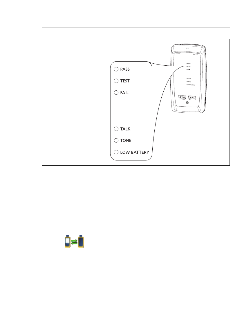
On a remote
The LEDs show the battery status at the end of the power-up
sequence, as shown in Figure 1.
12
Chapter 1: Get Acquainted
AC Adapter and Battery
84 % - 100 %
67 % - 83 %
51 % - 66 %
34 % - 50 %
18 % - 33 %
0 % - 17 %
Figure 1. LEDs Show the Remote’s Battery Status
GPU102.EPS
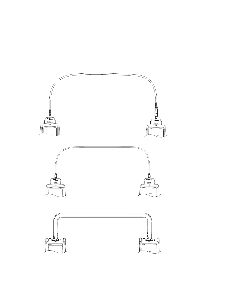
To see more information about a remote’s battery status
1 Make the connections shown in Figure 2 and turn on both
testers.
2 For CertiFiber Pro testers, select Smart Remote or Loopback
mode.
3 Make sure the connection icon shows at the top of the screen
().
4 Tap TOOLS, then tap Battery Status.
When the AC adapter is not connected, the screen shows the
Time Remaining, which is the approximate battery life at the
present rate of use.
13
Versiv Cabling Certification Product Family
DSX CableAnalyzer modules
with two channel adapters
and a patch cord
CertiFiber Pro
modules and two
fiber patch cords
DSX CableAnalyzer modules
with permanent link and
channel adapters
Users Manual
Verify Operation
The tester does a self test when you turn it on. If the tester shows
an error or does not turn on, refer to “If the Tester Does Not
Operate as Usual” on page 240.
Figure 2. Connections to See the Status of a Remote’s Battery
14
GPU148.EPS

Chapter 1: Get Acquainted
How to Use the Touchscreen
How to Use the Touchscreen
The Versiv main unit’s Taptive™ user interface lets you use a
touchscreen to control the tester. You can operate the
touchscreen with your fingertip or with a stylus that is made for
projected capacitance touchscreens.
Caution
For correct operation and to prevent damage to the
touchscreen:
Touch the screen only with your fingers or with a
stylus that is made for projected capacitance
touchscreens. Do not use too much force.
Do not touch the screen with sharp objects.
Note
The touchscreen will not respond if you tap it with
your fingernail or an incorrect type of stylus or if
you wear non-conductive gloves.
To use the touchscreen
To select an item on the screen, tap the item lightly with your
fingertip.
To scroll a screen, lightly touch the screen then move your
fingertip in the direction you want the screen to move.
On screens that show a plot, trace, or FiberInspector image,
you can drag some items, such as the measurement cursor on
a plot or trace or the image on a FiberInspector screen. These
screens also have a zoom function, as shown in Figure 3.
To clean the touchscreen
Turn off the tester, then use a soft, lint-free cloth that is moist
with a mild detergent.
Caution
When you clean the touchscreen, do not let liquid
get under the plastic around the touchscreen.
15

Versiv Cabling Certification Product Family
To quickly go back to 1:1
magnification, double-tap the
screen.
To zoom in, use the reversepinch gesture
To zoom out, use the pinch
gesture
To move the image, drag it in
any direction.
Users Manual
Figure 3. How to Zoom the Screen
16
GPU45.EPS
 Loading...