

Page 1

TNT 12000
X-Ray Test Tools
FBC 0003
March 2010, Rev. 2, 4/11
© 2010, 2011 Fluke Corporation. All rights reserved. Specifications are subject to change without notice.
All product names are trademarks of their respective companies.
Users Manual
Page 2

Warranty and Product Support
Fluke Biomedical, Radiation Management Services* products are warranted against
defects in material and workmanship.
• Instruments: Warranted for one year from date of shipment. The warranty for instruments that
require calibration may be extended each year by the GCL Extended Warranty
Program.
• Phantoms: Warranted for 6 months from date of shipment. The warranty excludes
disposable phantoms.
• CLEAR-Pb
• Software: Warranted for 90 days that it will perform substantially in accordance with its
• Consumables: Not
During the warranty period, Fluke Biomedical will, at its discretion, either repair or
replace the component or product that proves to be defective upon the company’s
examination. Repairs are limited to those components pertaining to functionality and not
cosmetic appearance.
The limited warranty becomes void if the product is disassembled, modified or repaired
by an unauthorized person or facility, or if the product’s functionality is impaired by
damage, abuse or failure to use and maintain the instrument according to the
manufacturer’s instructions.
®
: Warranted for 6 months from date of shipment against defects in material and
workmanship.
documentation.
covered under warranty.
To exercise this warranty, the owner must write or call a Fluke Biomedical customer
service representative to receive a Service Return Authorization (SRA). The owner must
send the product, transportation prepaid, to a specified service facility. Repairs will then
be made, and the product will be returned to the owner with transportation (normal,
service) prepaid. Repaired or replaced products are warranted for the balance of the
warranty period. For products not covered by warranty, the part repaired has a warranty
of 90 days.
Warranty Limitations: There are no warranties expressed or implied, including without
limitation any implied warranty of merchantability of fitness, which extend beyond that
discretion of the face hereof. This express warranty excludes coverage of and does not
provide relief for incidental or consequential damages of any kind or nature, including
but not limited to loss of use, loss of sales or inconvenience. This exclusive remedy of the
purchaser is limited to repair, recalibration or replacement of the instrument at the
Company’s discretion.
Disclaimer
Please Note: If an instrument is intended for the detection and measurement of ionizing
radiation, it should be used only by persons who have been trained in the appropriate
safety procedures to be followed in the presence of radiation and the proper
interpretation of the instrument’s readings. Instruction and precautions contained in the
manuals must be read before use and strictly followed. Failure to follow these
instructions and precautions may result in inaccurate readings and/or user hazard.
Battery and other preoperational checks should be performed prior to each use to assure
that the instrument is functioning properly.
* Includes products branded Nuclear Associates and Victoreen®. ©
Page 3

Notices
All Rights Reserved
Copyright 2008, Fluke Biomedical. No part of this publication may be reproduced, transmitted, transcribed, stored in a retrieval
system, or translated into any language without the written permission of Fluke Biomedical.
Copyright Release
Fluke Biomedical agrees to a limited copyright release that allows you to reproduce manuals and other printed materials for use in
service training programs and other technical publications. If you would like other reproductions or distributions, submit a written
request to Fluke Biomedical.
Unpacking and Inspection
Follow standard receiving practices upon receipt of the instrument. Check the shipping carton for damage. If damage is found, stop
unpacking the instrument. Notify the carrier and ask for an agent to be present while the instrument is unpacked. There are no special
unpacking instructions, but be careful not to damage the instrument when unpacking it. Inspect the instrument for physical damage such
as bent or broken parts, dents, or scratches.
Technical Support
For application support or answers to technical questions, either email radtechsupport@flukebiomedical.com or call 1-800- 850-4608 or
1-440-498-2560. Technical support is also available at http://www.flukebiomedical.com/techsupport.
Claims
Our routine method of shipment is via common carrier, FOB origin. Upon delivery, if physical damage is found, retain all packing
materials in their original condition and contact the carrier immediately to file a claim. If the instrument is delivered in good physical
condition but does not operate within specifications, or if there are any other problems not caused by shipping damage, please contact
Fluke Biomedical or your local sales representative.
Standard Terms and Conditions
Refunds and Credits
Please note that only serialized products and their accessory items (i.e., products and items bearing a distinct serial number
tag) are eligible for partial refund and/or credit. Nonserialized parts and accessory items (e.g., cables, carrying cases,
auxiliary modules, etc.) are not eligible for return or refund. Only products returned within 90 days from the date of original
purchase are eligible for refund/credit. In order to receive a partial refund/credit of a product purchase price on a serialized product, the
product must not have been damaged by the customer or by the carrier chosen by the customer to return the goods, and the product
must be returned complete (meaning with all manuals, cables, accessories, etc.) and in “as new” and resalable condition. Products not
returned within 90 days of purchase, or products which are not in “as new” and resalable condition, are not eligible for credit return and
will be returned to the customer. The Return Procedure (see below) must be followed to assure prompt refund/credit.
Restocking Charges
Products returned within 30 days of original purchase are subject to a minimum restocking fee of 25 %. Products returned in excess of
30 days after purchase, but prior to 90 days, are subject to management approval. Additional charges for damage and/or missing parts
and accessories will be applied to all returns.
Return Procedure
All items being returned (including all warranty-claim shipments) must be sent freight-prepaid to our factory location. When you return
an instrument to Fluke Biomedical, we recommend using United Parcel Service, Federal Express, or Air Parcel Post. We also
recommend that you insure your shipment for its actual replacement cost. Fluke Biomedical will not be responsible for lost shipments
or instruments that are received in damaged condition due to improper packaging or handling.
Use the original carton and packaging material for shipment. If they are not available, we recommend the following guide for
repackaging:
Use a double-walled carton of sufficient strength for the weight being shipped.
Use heavy paper or cardboard to protect all instrument surfaces. Use nonabrasive material around all projecting parts.
Use at least four inches of tightly packed, industry-approved, shock-absorbent material around the instrument.
Returns for partial refund/credit:
Every product returned for refund/credit must be accompanied by a Return Material Authorization (RMA) number, obtained from our
Customer Support Group at 1-800-850-4608 or 1-440-498-2564 or email orders@flukebiomedical.com.
Page 4

Repair and calibration:
To find the nearest service center, go to www.flukebiomedical.com/service
In the U.S.A.:
Cleveland Calibration Lab
Tel: 1-800-850-4606 ext. 2564
Email: globalcal@flukebiomedical.com
Everett Calibration Lab
Tel: 1-888-993-5853
Email: service.status@fluke.com
In Europe:
Eindhoven Calibration Lab
Tel: +31-402-675300
Email: ServiceDesk@fluke.com
, or
Certification
This instrument was thoroughly tested and inspected. It was found to meet Fluke Biomedical’s manufacturing specifications when it
was shipped from the factory. Calibration measurements are traceable to the National Institute of Standards and Technology (NIST).
Devices for which there are no NIST calibration standards are measured against in-house performance standards using accepted test
procedures.
WARNING
Unauthorized user modifications or application beyond the published specifications may result in electrical shock hazards or
improper operation. Fluke Biomedical will not be responsible for any injuries sustained due to unauthorized equipment
modifications.
Restrictions and Liabilities
Information in this document is subject to change and does not represent a commitment by Fluke Biomedical. Changes made
to the information in this document will be incorporated in new editions of the publication. No responsibility is assumed by
Fluke Biomedical for the use or reliability of software or equipment that is not supplied by Fluke Biomedical, or by its
affiliated dealers.
Manufacturing Location
The TNT 12000 X-Ray Test device is manufactured in Cleveland, Ohio by Fluke
Biomedical, 6045 Cochran Rd., Cleveland, OH, U.S.A.
Page 5

Table of Contents
Chapter Title Page
1 Introduction ......................................................................................... 1-1
Introduction........................................................................................................ 1-3
Unpacking and Inspection.................................................................................. 1-3
Storage ............................................................................................................... 1-3
General Safety Considerations........................................................................... 1-3
Symbols ............................................................................................................. 1-4
RF Certification ................................................................................................. 1-4
United States.................................................................................................. 1-5
Canada ........................................................................................................... 1-5
Europe ........................................................................................................... 1-5
Japan.............................................................................................................. 1-5
Familiarization................................................................................................... 1-6
How to Charge the Battery ................................................................................ 1-9
Accessories ........................................................................................................ 1-10
Specifications..................................................................................................... 1-11
2 Operation ............................................................................................. 2-1
Introduction........................................................................................................ 2-3
Safety Information ............................................................................................. 2-3
How to Set Up the System................................................................................. 2-3
Display to Detector Communications............................................................ 2-3
How to Setup a Wireless Connection........................................................ 2-4
How to Setup a USB Connection.............................................................. 2-4
Multiple Detector Connections ................................................................. 2-4
Communication Settings ........................................................................... 2-4
How to Use the X-ray Detector (TNT 12000WD) ............................................ 2-5
How to Position the X-ray Detector .............................................................. 2-6
Detector Placement with Above Table X-ray Source ............................... 2-6
Detector Placement with Below Table X-ray Source ............................... 2-7
How to Measure X-ray Parameters ............................................................... 2-7
X-ray Display Configuration..................................................................... 2-8
Measurement Mode Setup......................................................................... 2-9
Measurement Mode Profile Parameters .................................................... 2-9
How to Set a Detector Profile ................................................................... 2-10
i
Page 6

TNT 12000
Users Manual
Auto Profiles.................................................................................................. 2-11
Default Profiles.............................................................................................. 2-11
How to Change Profile Parameters ............................................................... 2-12
How to Make a User-Defined Profile............................................................ 2-13
How to Enter a Delay .................................................................................... 2-15
How to Use the Dosimeter Detector (TNT 12000 DoseMate) .......................... 2-15
Ion Chamber Selection and Setup ................................................................. 2-16
Ion Chamber Connection and Placement ...................................................... 2-16
How to Place the Ion Chamber for Over-Table X-ray Sources ................ 2-17
How to Place the Ion Chamber for Under-Table X-ray Sources .............. 2-20
How to Place the Ion Chamber for Horizontal X-ray Beams.................... 2-22
How to Place the Ion Chamber in Limited Access Situations .................. 2-23
How to Make a Dosimeter Measurement ...................................................... 2-24
Ion Chamber Setup.................................................................................... 2-24
Dosimeter Measurements.......................................................................... 2-26
How to Add an Ion Chamber Definition or Cal Factor............................. 2-26
How to Edit an Ion Chamber Definition or Cal Factor ............................. 2-29
How to Delete an Ion Chamber Definition or Cal Factor ......................... 2-30
Measurement Mode Selection................................................................... 2-31
How to Set Units of Measurement ............................................................ 2-32
Air Density Correction.............................................................................. 2-34
How to Adjust the Internal Temperature/Pressure Sensor ........................ 2-36
Dosimeter Status ....................................................................................... 2-37
How to Use the mAs Detector (TNT 12000 mAs) ............................................ 2-38
How to Connect to the X-ray Tube for mAs Measurements ......................... 2-39
Shunt Connections .................................................................................... 2-40
Clamp Connections ................................................................................... 2-43
How to Measure mAs.................................................................................... 2-43
Setup Options..................................................................................................... 2-44
Connection Option......................................................................................... 2-45
How to Set Power Settings ............................................................................ 2-45
Detector Battery Charge Level.................................................................. 2-46
Display Off Time ...................................................................................... 2-46
Low Power Time....................................................................................... 2-46
System Off Time ....................................................................................... 2-47
Brightness.................................................................................................. 2-47
How to Set the Date and Time....................................................................... 2-47
3 Microsoft Excel Add-In Software ....................................................... 3-1
Introduction........................................................................................................ 3-3
System Requirements ........................................................................................ 3-3
How to Install the Add-In .................................................................................. 3-3
How to Install the Excel Add-In Software .................................................... 3-3
How to Install the TNT 12000 Vendor Class Driver..................................... 3-4
How to Uninstall the Add-In.............................................................................. 3-5
How to Uninstall the Excel Add-In Software................................................ 3-5
How to Uninstall the TNT 12000 Vendor Class Driver ................................ 3-6
Communication between a PC and Detector ..................................................... 3-7
How Initialize the TNT 12000 Add-In Software............................................... 3-8
TNT 12000WD Toolbar Options....................................................................... 3-9
DoseMate Toolbar Options................................................................................ 3-11
mAs Toolbar Options......................................................................................... 3-13
ii
Page 7

Contents (continued)
4 Maintenance......................................................................................... 4-1
Introduction........................................................................................................ 4-3
Ion Chamber Care.............................................................................................. 4-3
Cleaning............................................................................................................. 4-3
Firmware Upgrade ............................................................................................. 4-3
Detector ......................................................................................................... 4-3
Display........................................................................................................... 4-4
Service and Calibration...................................................................................... 4-4
Packing .......................................................................................................... 4-4
Shipping......................................................................................................... 4-4
Appendices
A Model 96020C Ion Chamber....................................................................... A-1
B Model 96035B Ion Chamber ....................................................................... B-1
C Model 500-100 CT Probe............................................................................ C-1
D Model 500-200 CT Probe............................................................................ D-1
E TNT 12000WD kVp, Exposure, and Exposure Time Measurement........... E-1
F Warnings and Error Messages..................................................................... F-1
G Troubleshooting .......................................................................................... G-1
H PTB Information ......................................................................................... H-1
iii
Page 8

TNT 12000
Users Manual
iv
Page 9

List of Tables
Table Title Page
1-1. Symbols.................................................................................................................. 1-4
1-2. Display Components .............................................................................................. 1-6
1-3. X-ray Detector Components................................................................................... 1-7
1-4. Dose Detector Components.................................................................................... 1-8
1-5. Battery Status Indicator.......................................................................................... 1-10
1-6. Accessories............................................................................................................. 1-10
1-7. Optional Accessories.............................................................................................. 1-11
2-1. Communication Status Indicator............................................................................ 2-3
2-2. Settable Profile Parameters .................................................................................... 2-9
2-3. Default Parameter Values for Each Measurement Mode....................................... 2-12
2-4. Cal Factor Units ..................................................................................................... 2-29
2-5. Dosimeter Measurement Modes............................................................................. 2-31
2-6. Dose Rate Values ................................................................................................... 2-33
2-7. mAs Current Ranges .............................................................................................. 2-39
3-1. TNT 12000WD Excel Add-In Menu and Toolbar Options ................................... 3-10
3-2. DoseMate Excel Add-In Menu and Toolbar Options ............................................ 3-12
3-3. mAs Excel Add-In Menu and Toolbar Options ..................................................... 3-14
v
Page 10

TNT 12000
Users Manual
vi
Page 11

List of Figures
Figure Title Page
1-1. Charging Methods.................................................................................................. 1-9
2-1. Wired (USB) Connection....................................................................................... 2-4
2-2. Connection Screen ................................................................................................. 2-5
2-3. X-ray Detector Alignment Marks .......................................................................... 2-6
2-4. X-ray Detector Setup for Above Table X-ray Source............................................ 2-6
2-5. X-ray Detector Setup for Below Table X-ray Source ............................................ 2-7
2-6. X-ray Detector Measurement Screen ..................................................................... 2-8
2-7. Mode Setup Screen ................................................................................................ 2-9
2-8. Ion Chamber Connection to Dosimeter.................................................................. 2-17
2-9. Test Stand Configuration for Over-Table Tubes.................................................... 2-18
2-10. Test Stand Configuration for Under-Table X-ray Tube ......................................... 2-20
2-11. Test Stand Configuration for Horizontal Tube....................................................... 2-22
2-12. Ion Chamber Cable Stem ....................................................................................... 2-23
2-13. Ion Chamber Notification Screen........................................................................... 2-24
2-14. Ion Chamber Setup Screen ..................................................................................... 2-25
2-15. Dosimeter Measurement Screen............................................................................. 2-26
2-16. mAs Measurement Option Screen.......................................................................... 2-38
2-17. Shunt or Clamp Screen........................................................................................... 2-39
2-18. Direct mAs Shunt Connection to Current Jacks..................................................... 2-41
2-19. mAs Test Leads Connection .................................................................................. 2-42
2-20. mAs Measurement Screen...................................................................................... 2-43
2-21. Setup Screen........................................................................................................... 2-44
2-22. Setup Screen from mAs Measurement ................................................................... 2-44
2-23. Setup Screen with mAs and DoseMater Detectors Connected .............................. 2-45
2-24. Power Setting Screen ............................................................................................. 2-45
2-25. Sleep Mode Display ............................................................................................... 2-46
2-26. Date and Time Setting Screen ................................................................................ 2-47
3-1. InstallShield Wizard............................................................................................... 3-3
3-2. USB Connection between PC and Detector........................................................... 3-4
3-3. Found New Hardware Wizard Window................................................................. 3-5
3-4. Add or Remove Programs Dialog .......................................................................... 3-6
3-5. Computer Management Windows.......................................................................... 3-7
3-6. USB Connection between PC and Detector........................................................... 3-7
3-7. Wireless Connection Between PC and Detector .................................................... 3-8
3-8. Detector Connection Window................................................................................ 3-9
vii
Page 12

TNT 12000
Users Manual
3-9. TNT 12000WD Excel Add-In Menu and Toolbar (Excel 2007) ........................... 3-10
3-10. TNT 12000WD Excel Add-In Menu and Toolbar (Excel 2003) ........................... 3-11
3-11. DoseMate Excel Add-In Menu and Toolbar (Excel 2007) .................................... 3-11
3-12. DoseMate Excel Add-In Menu and Toolbar (Excel 2003) .................................... 3-13
3-13. mAs Excel Add-In Menu and Toolbar (Excel 2007) ............................................. 3-13
3-14. mAs Excel Add-In Menu and Toolbar (Excel 2003) ............................................. 3-14
viii
Page 13

Chapter 1
Introduction
Title Page
Introduction..........................................................................................................1-3
Unpacking and Inspection....................................................................................1-3
Storage .................................................................................................................1-3
General Safety Considerations.............................................................................1-3
Symbols ...............................................................................................................1-4
RF Certification ...................................................................................................1-4
United States....................................................................................................1-5
Canada .............................................................................................................1-5
Europe .............................................................................................................1-5
Japan................................................................................................................1-5
Familiarization.....................................................................................................1-6
How to Charge the Battery ..................................................................................1-9
Accessories ..........................................................................................................1-10
Specifications.......................................................................................................1-11
1-1
Page 14

TNT 12000
Users Manual
1-2
Page 15

Introduction
Introduction 1
Introduction
The Fluke Biomedical TNT 12000 X-ray Test Tools (the TNT 12000) are used to
calibrate and service diagnostic X-ray imaging systems.
The TNT 12000 X-ray Test Tools has these parts:
• TNT 12000WD X-ray Detector option (the X-ray Detector). The X-ray Detector
contains an array of solid-state sensors and filters that measure kV, Dose, Half-Value
Layer (HVL), and exposure time.
• TNT 12000 DoseMate option (the Dosimeter Detector). With its related ion
chambers, the Dosimeter Detector measures dose and rate on all X-ray modalities:
radiographic, mammographic, dental, cine, fluoroscopic, and CT.
• TNT 12000 mAs option (the mAs Detector) to measure X-ray tube current over time.
Use the mAs Detector on radiographic (or Dental or Mammography) and
fluoroscopic X-ray imaging modalities. The mAs option is installed in the X-ray or
Dosimeter Detectors.
• TNT 12000 Display (the Display). The Display contains a 320 x 240 color LCD, four
navigation buttons, an ENTER button, and a power button. The display controls testsystem functions and shows all system measurements.
• TNT 12000/DoseMate/mAs CD that contains an Excel Add-in to control the test
system and import all measurements.
• AC Power Adapter used to charge the rechargeable batteries in the X-ray Detector,
Dosimeter Detector, mAs Detector, and the Display.
The TNT 12000 options communicate between the detectors and the display or computer
through a wireless (ZigBee) or wired (USB) connection.
Unpacking and Inspection
The TNT 12000 is shipped in a container designed to prevent damage during shipment.
Examine the components for damage, and immediately report any damage to the shipper.
Keep the damaged shipping container and packing material for inspection by the carrier.
The shipping container contains foam inserts to prevent damage during
shipment. Keep these and the container for future shipment.
When you unpack the TNT 12000, compare the parts to the packing list. If you ordered
the mAs option, make sure it is installed in a Detector by looking for an mAs input jack
on a Detector. See the Familiarization section later in this chapter. Report any shortage to
the place of purchase.
Storage
To store the TNT 12000, put it in its carrying case. Keep it in an environment free of
corrosive material and within the storage temperature and operating humidity ranges
shown in the specifications. Also prevent vibration and shock to the system.
Note
General Safety Considerations
In this manual, a Warning identifies conditions and actions that pose hazards to the user.
A Caution identifies conditions and actions that may damage the test equipment or the
equipment under test.
Symbols used on the test system or in this manual are explained in Table 1-1.
1-3
Page 16

TNT 12000
Users Manual
To ensure safe operation of the Test System, fully observe all instructions and warnings
contained in this manual.
XW Warning
To avoid possible electrical shock or personal injury, follow
these guidelines:
• Use the TNT 12000 only in the manner specified by the
manufacturer.
• Do not use the product if it operates abnormally.
• Use only the ac adapter provided with the system.
• Ensure that the external power source is properly rated for the
system.
W Caution
To avoid damage to the TNT 12000 or adverse affects on its
performance, follow these guidelines:
• Allow only qualified technical personnel to service the
system.
• Do not expose the system to temperature extremes.
Ambient temperatures should remain between 0 °C and
35 °C. System performance may be adversely affected if
temperatures fluctuate above or below this range.
• Clean the TNT 12000 by gently wiping down with a clean,
lint-free cloth dampened with a mild detergent solution. Do
not immerse the unit in liquid.
Symbols
Table 1-1 describes the symbols associated with the TNT 12000.
Table 1-1. Symbols
Symbol Description Symbol Description
X Hazardous voltage P Conforms to European Union directives
W Important information, refer to manual ;
• Complies with RoHS directives Ž Complies with Part 15 of the FCC rules
Do not dispose of this product as
~
unsorted municipal waste. Go to
Fluke’s website for recycling
information.
´
Conforms to relevant Australian EMC
requirements
This product contains a Lithium-ion
battery. Do not mix with solid waste
stream. Spent batteries should be
disposed of by a qualified recycler or
hazardous materials handler per local
regulations. Contact your authorized Fluke
Service Center for recycling information.
1-4
RF Certification
The TNT 12000 contains radio transceivers that are used for wireless communication
between the Display and the Detectors. The transceivers operate in the 2.4 GHz
frequency band with a maximum transmitting power of 1 mW. The transceivers have
been tested and certified for use in various areas worldwide.
Page 17

Introduction
RF Certification 1
United States
The transceivers used in the TNT 12000 have been approved for use in the United States
by FCC Part 15 certification, FCC ID: OUR-XBEE. The following statement
accompanies the device:
“Contains FCC ID: OUR-XBEE"
The enclosed device complies with Part 15 of the FCC rules. Operation is subject to the
following two conditions: (1) this device may not cause harmful interference and (2) this
device must accept any interference received, including interference that may cause
undesired operation.
This equipment has been tested and found to comply with the limits for a Class A digital
device, pursuant to Part 15 of the FCC Rules. These limits are designed to provide
reasonable protection against harmful interference in a commercial environment. This
equipment generates, uses, and can radiate radio frequency energy and, if not installed
and used in accordance with the instructions, may cause harmful interference to radio
communications. However, there is no guarantee that interference will not occur in a
particular installation.
If this equipment does cause harmful interference to radio or television reception, which
can be determined by turning the equipment off and on, the user is encouraged to try to
correct the interference by one or more of the following measures: Re-orient or relocate
the receiving antenna, increase the separation between the equipment and receiver,
connect equipment and receiver to outlets on different circuits, or consult the dealer or an
experienced radio/television technician for help.
Canada
Europe
Japan
W Warning
To satisfy FCC RF exposure requirements for mobile
transmitting devices, a separation distance of 20 cm or more
should be maintained between the antenna of this device and
persons during device operation. To ensure compliance,
operations at closer than this distance is not recommended.
The antenna used for this transmitter must not be co-located in
conjunction with any other antenna or transmitter.
The transceiver used in the TNT 12000 has been certified for use in Canada, IC
certification number IC: 4214A-XBEE.
The transceiver used in the TNT 12000 conforms to European Union EMC Directive
2004/108/EC, ETSI EN 301 489-1 and EN 301 489-17; and R&TTE Directive
1999/5/EC, ETSI EN300 328.
Japan ID: 005NYCA0378
1-5
Page 18
TNT 12000
Users Manual
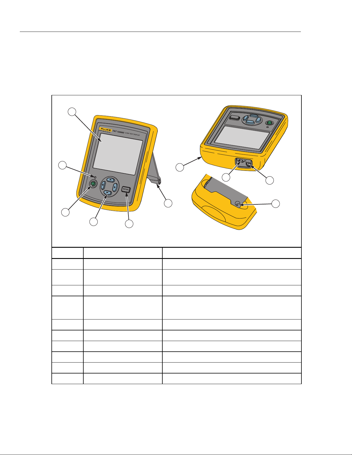
Familiarization
To use the TNT 12000, you must first connect the Display to the X-ray Detector or
Dosimeter Detector. Tables 1-2 through 1-4 shows the controls, indicators, and
connectors of the Display and Detectors.
Table 1-2. Display Components
1
2
3
4
Item Name Description
A
B
C
D
E
LCD Panel 320X240 color display
Battery-status Indicator Tri color LED indicating the battery status of the display.
On/Off Switch Powers the display On/Off
Navigational Keys:
Left, Right, Up, and Down keys
Enter key Selects the menu option on the display screen
5
7
8
RESET
6
Refer to the Battery Charging section for more details.
Moves the cursor through the menu options on the display
screen in various directions.
Note: The cursor movement is circular
9
10
fct02.eps
1-6
F
G
H
I
J
Stand Display support stand
Holster Protective cover for the display
USB Connector To connect the detector or a Computer via USB cable
AC adapter connector Connects the ac adapter
Reset switch Resets the display
Note
A short beep sounds for a valid key press, and a long beep sounds for an
invalid key press.
Page 19
Introduction
Familiarization 1
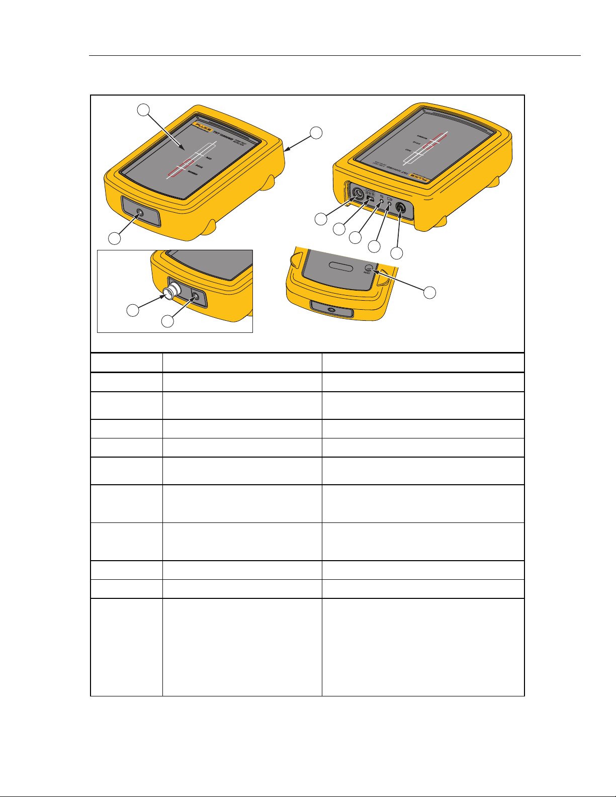
Table 1-3. X-ray Detector Components
1
3
4
5
2
mAs Option
Installed
10
2
6
7
8
9
fct01.eps
Item Name Description
A
B
C
D
E
F
G
H
I
J
Exposure Surface The surface to be exposed to x-ray radiation
Threaded Insert Secures the detector to a test stand, such as a
camera tripod
Holster Protective cover for the display
AC adapter connector Connects the ac adapter
USB Connector To connect the detector or a Computer via USB
cable
Communication status LED Indicates the communication status (see the
Display to Detector Communications section in
Chapter 1)
Battery-status Indicator Tri color LED indicating the battery status of the
display. Refer to the Battery Charging section
for more details.
On/Off Switch Powers the Detector On/Off
Reset switch Resets the Detector
mAs input jack (when mAs option is
installed)
Male coaxial BNC jack for connection to the
mA/mAs interface cable
WCaution
To avoid damage to the Detector,
never connect to generator mA/mAs
taps without the TNT 12000 mAs
shunt.
1-7
Page 20

TNT 12000
Users Manual
Table 1-4. Dose Detector Components
3
4
5
1
2
6
7
8
9
fct11.eps
Item Name Description
A
mAs input jack (when mAs option is installed) Male coaxial BNC jack for connection to the
mA/mAs interface cable
WCaution
To avoid damage to the Detector,
never connect to generator
mA/mAs taps without the TNT
12000 mAs shunt.
B
C
D
E
F
G
Ion Chamber Connector Triaxial input connection for the Ion Chamber.
Holster Protective cover for Dosimeter
AC adapter connector Connects the ac adapter
USB Connector To connect the Detector or a computer via
USB cable
Communications Status Indicator Indicates the communication status (see the
Display to Detector Communications section
in Chapter 1)
Battery-status Indicator Tri color LED indicating the battery status of
the display. Refer to the Battery Charging
section for more details.
1-8
H
I
On/Off Switch Powers the Detector On and Off.
Reset switch Resets the Dose Detector
Page 21
Introduction
How to Charge the Battery 1
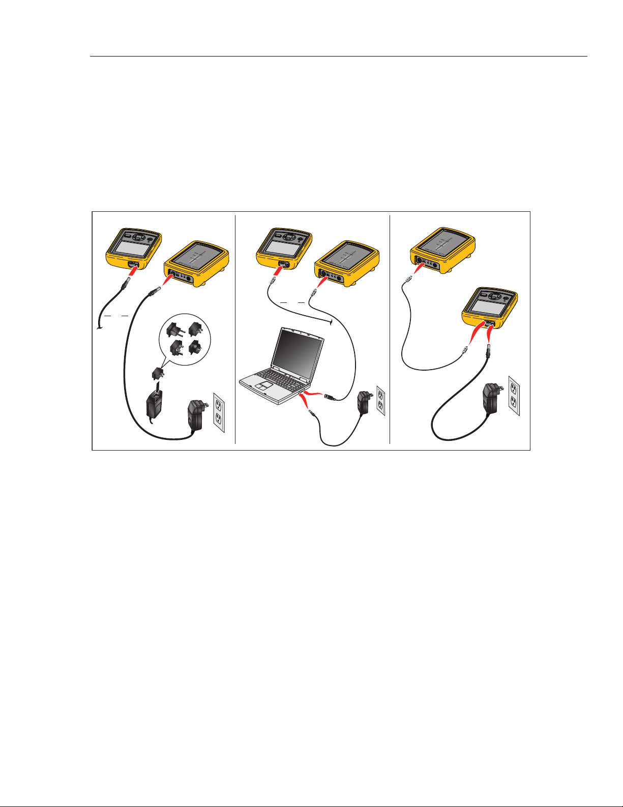
How to Charge the Battery
Charging the internal batteries of the detectors and display from mains power can be done
in three different configurations as shown in Figure 1-1.
WCaution
To prevent damage to the TNT 12000, do not leave batteries
unused for an extended period of time. When a battery has not
been used for six months, check the charge status and charge
if necessary.
Power Source Computer to Power Source Detector to Display to Power Source
OR
OR
Figure 1-1. Charging Methods
fct10.eps
To charge a Detector or the Display directly from mains power, connect the ac-power
adapter directly to the ac adapter connector on a Detector or the Display. To charge a
Detector and the Display simultaneously, connect the ac adapter to the ac adapter
connection on the Display and then, using the Mini-B to Type-A USB cable, connect the
Detector to the Display.
Note
See the markings on the ends of the cable to identify the Mini-A and Mini-B
ends.
A Detector or Display battery can also be charged through a USB connector on a PC.
Connect the Display or Detector to a PC USB port using the Mini-A to Type-A USB
cable.
Both Detectors and the Display have a battery-status indicator to indicate the condition of
the internal battery. The indicator is a tri-color LED that shows the level of charge on the
internal battery. Table 1-5 explains the battery-status indicator levels.
1-9
Page 22
TNT 12000
Users Manual
Table 1-5. Battery Status Indicator
Color Description
Blue Battery is fully charged.
Green Battery is charging.
Off Unit is not connected to a charging power source and is operating on battery power.
Yellow Battery is approximately 20 % charged.
Red Battery has 10 % charge and will turn off in two minutes.
Accessories
Items shown in Table 1-6 are standard accessories provided with the TNT 12000. Some
accessories are only associated with specific options. Items in Table 1-7 are optional.
Contact your Fluke Biomedical representative to purchase the accessories shown below.
Table 1-6. Accessories
Accessory Fluke Biomedical Part No
Cable, Type A to Mini B USB 3346027
Cable, Mini A to Mini B USB 3346030
ZigBee Dongle 3341333
AC Power Adapter 3548014
Multi-Prong Adapter 3549414
CD, TNT 12000/DoseMate/mAs 3586667
Ansur Demo CD 2795488
DoseMate Option
Carrying Case, DoseMate/mAs 3586528
Test Stand, DoseMate 3586537
HVL Filter Set 3264115
Adapter Stem 3264091
Tirax Cable, Male to Male, BNC, 1.82 m (6 ft) 3586644
mAs Option
mA Cable Assembly, BNC (male to female) 1918780
mA Shunt Assembly 3586555
1-10
Alligator Clip, Banana Plug (Red) 1942964
Alligator Clip, Banana Plug (Black) 1942920
Connector, BNC (F) to Binding Posts 1938315
Connector, BNC (F) to Double Banana Plug 1633042
Page 23

Introduction
Specifications 1
Table 1-7. Optional Accessories
Accessory Fluke Biomedical Part No
Ansur Plug In, TNT 12000 3337356
Optional Accessories for the DoseMate Option
Diagnostic Ionization Chamber, 150cc, Model 96020C 2549992
Diagnostic Ionization Chamber, 15cc, Model 96035B 2550024
CT Ion Chamber, 3cc, Model 500-100 2549734
CT Ion Chamber, 10cc, Model 500-200 2549741
Triax Cable, Male to Male, BNC, 6.1 m (20 ft) 3265786
Optional Accessories for the mAs Option
Non-Invasive mA/mAs Clamp 3586746
mA Cable Assembly, BNC, 6.1 m (20 ft) (male to female) 2118136
Specifications
Physical
Display Screen........................................................ 320X240 Color LCD
Size
Display ................................................................ 15.24 cm X 11.43 cm X 4.45 cm (6 in X 4.5 in X 1.75 in)
Detector ..............................................................15.24 cm X 11.43 cm X 4.45 cm (6 in X 4.5 in X 1.75 in)
Weight
Display ................................................................ 347 g (0.93 lb)
X-ray Detector w/o mAs...................................... 560 g (1.5 lb)
X-ray Detector with mAs ..................................... 560 g (1.5 lb)
DoseMate w/o mAs............................................. 392 g (1.05 lb)
DoseMate with mAs............................................ 392 g (1.05 lb)
Electrical
Battery
Battery Type ....................................................... Lithium-Ion, 3.7 V, 4000 mAh
Battery Charging time ......................................... Approx. 5 hr
Battery Discharge time ....................................... Approx. 8 hr
Battery Cutoff Voltage......................................... 3.0 V
AC Adapter
Input Voltage....................................................... 100 V ac to 240 V ac
Input Frequency.................................................. 50/60 Hz
Input Current....................................................... 0.5 A (rms)
Output Voltage.................................................... +6 V dc
Output Current .................................................... 2500 mA (max.)
1-11
Page 24

TNT 12000
Users Manual
1-12
Environmental
Operating Temperature........................................... 0 °C to 35 °C (32 °F to 95 °F)
Storage Temperature.............................................. -35 °C to 50 °C (-31 °F to +122 °F)
Operating Humidity ................................................. 20 % to 80 % RH (Non Condensing)
Wireless Range....................................................... 30 m (100 ft)
X-ray Specifications
kVp
Units........................................................................ kVp Average (Average of peaks during a specified interval)
kVp Max (Highest peak during a specified interval)
PPV (Peak Practical Voltage)
Ranges
Radio/Fluoro/Dental Modes (W,Al) ......................... 40 kV–150 kV
Mammo Mode
Mo/Mo................................................................. 22 kV–35 kV
Rh/Rh.................................................................. 25 kV– 49 kV
Mo/Rh ................................................................. 22 kV–40 kV
Mo/Al................................................................... 22 kV– 49 kV
Rh/Al ................................................................... 25 kV–49 kV
W/Rh................................................................... 22 kV–39 kV
W/Ag ................................................................... 22 kV–39 kV
Resolution: .............................................................. 0.1 kV
Accuracy (including calibration uncertainty)
Radio/Fluoro/Dental Modes .................................... ±2 % or ±1 kV, whichever is greater
Mammo Mode ......................................................... ±2 % or ±0.7 kV, whichever is greater
Reproducibility ........................................................ ±1 % (standard deviation % of 5 readings)
Filtration Correction Range
Radio/Fluoro/Dental Modes .................................... 1–10 mm Al or equivalent
Mammo Mode ......................................................... 0–0.4 mm Al or equivalent added filtration (0–0.2 mm AI below 25 kV)
Dose/Exposure
Units........................................................................ Roentgens (R)
Grays (Gy)
Range ..................................................................... 0.5 mR–999 R
5 mGy–999 Gy
Resolution ............................................................... 1 µR
0.01 µGy
Accuracy ................................................................. ±5 %
Reproducibility ........................................................ ±0.5 % (standard deviation % of five readings)
Filtration Correction Range
Radio/Fluoro/Dental Modes ................................ 10 mm Al or equivalent
Mammo Mode..................................................... 0–0.4 mm Al or equivalent added filtration (0– 0.2 mm AI below 25 kV)
kV Correction Ranges
Radio/Fluoro/Dental Modes ................................ 40 kV–150 kV
Mammo Mode: Mo/Mo........................................ 22 kV–35 kV
Dose/Exposure Rate
Units........................................................................ Roentgens per hour, minute, second, pulse (R/hr, R/min, R/sec,
R/Pulse)
Grays per hour, minute, second, pulse (Gy/hr, Gy/min, Gy/sec,
Gy/Pulse)
Range ..................................................................... 8 mR/s–10 R/s
70 µGy/s–100 mGy/s
130 µR/Pulse–160 mR/Pulse (@ 60 PPS)
12 µGy/Pulse–1.4 mGy/Pulse (@ 60 PPS)
Resolution ............................................................... 1 µR/s
0.01 µGy/s
0.02 µR/Pulse (@ 60 PPS)
0.2 nGy/Pulse (@ 60 PPS)
Accuracy ................................................................. ±5 %
Page 25

Introduction
Specifications 1
Filtration Correction Range
Radio/Fluro/Dental Modes .................................. 1-10 mm Al or equivalent
Mammo Mode..................................................... 0–0.4 mm Al or equivalent added filtration (0–0.2 mmAI below 25 kV)
kV Correction Range
Radio/Fluro/Dental Modes .................................. 40 kV–150 kV
Mammo Mode: Mo/Mo........................................ 22 kV-35 kV
Exposure Time–Radiographic Modes
Range @ stated accuracy
Milliseconds ........................................................10–9999 ms
Pulses ................................................................. 1–999 pulses
Resolution
Milliseconds ........................................................0.1 ms
Pulses ................................................................. 1 pulse
Accuracy
Milliseconds ........................................................1 % or 0.5 ms
Pulses ................................................................. ±1 pulse
Reproducibility
Milliseconds ........................................................1 % or 0.5 ms
Pulses ................................................................. ±1 pulse
Elapsed Time–Fluoro Modes
Range ..................................................................... 10–9999 seconds
Resolution ............................................................... 0.1 second
Accuracy ................................................................. 1 % or 0.5 second
Average Pulse Rate – Pulsed Fluoro
Range ..................................................................... 1–999 pps (pulses per second)
Resolution ............................................................... 1 pps
Accuracy ................................................................. 1 pps
Average Pulse Width – Pulsed Fluoro
Range ..................................................................... 10–999 ms
Resolution ............................................................... 0.1 ms
Accuracy ................................................................. 1% or 0.5 ms
HVL (Half Value Layer)
Range
Radio/Fluoro/Dental Modes ................................ 1.2–10 mm Al (equivalent)
Mammo Mode..................................................... 0.2–0.6 mm Al (equivalent)
Resolution
Radio/Fluoro/Dental Modes ................................ 0.1 mm Al (equivalent)
Mammo Mode..................................................... 0.01 mm Al (equivalent)
Accuracy
Radio/Fluoro/Dental Modes ................................ ±10 % or 0.2 mm Al (equivalent)
Mammo Mode: Mo/Mo........................................ ± 5 % or 0.05 mm Al (equivalent)
mAs Specifications
Accuracy
With Invasive Shunt ............................................ ±2 % of rdg ±2 digits
With Non-Invasive Shunt ....................................±3 % ±3 mA
Invasive mA/mAs Range......................................... 0.00 – 99.99 mA/mAs
100.0 – 999.9 mA/mAs
1000 – 1999 mA/mAs
Non-Invasive mA/mAs Ranges............................... 0 – 999.9 mA/mAs
1000 – 3999 mA/mAs
Trigger Levels
Invasive Shunt ....................................................3 mA
Non-Invasive Shunt ............................................ 6 mA
Input Jack................................................................ Male Coaxial BNC
mA/mAs Interface Cable ......................................... 152.4 cm (60 in) BNC Male – Female, 50 Ohm cable with strain relief
1-13
Page 26
TNT 12000
Users Manual
Adapters.................................................................. BNC Female to Binding Posts, BNC Female to Banana Plug
Test Leads .............................................................. 91.4 cm (36 in) safety set with finger guards on probes and shrouded
banana plugs
Invasive Shunt
Shunt Impedance.................................................... 1 Ohm
Sensitivity................................................................ 1 mV per mA
Shunt Signal Input Limit.......................................... 1 A for 30 seconds (Limit set by power dissipation rating of shunt
resistors. Maximum common mode voltage is 500 V).
Input/Output ............................................................ 4 mm Binding posts, 4 mm Banana Plugs
Size ......................................................................... 4.45 cm x 3.66 cm x 1.75 cm (1.75 in x 1.44 in x 0.69 in)
Weight..................................................................... 45 g (0.1 lb)
Non-Invasive Clamp
Range ..................................................................... 0 – 4 Amps
Sensitivity................................................................ 100 mV/A
Power Source ......................................................... 2 x 1.5 V AA UM3 Batteries
Current Consumption.............................................. 10 mA
Operating Condition ................................................ -10 °C to +50 °C at 85 % max. RH
DoseMate Specifications
Accuracy ................................................................. ±1 % of rdg ±2 of range resolution steps (see DoseMate Measurment
Ranges) over the range of 18 to 28 °C and ±2 of reading ±2 range
resolution steps over the full operating temperature range of 0 to
35 °C. This accuracy is exclusive of all ion chamber effects. A 3 %
NIST traceable calibration is provided with each system.
Bias Voltage............................................................ 300 V. The bias voltage is removed from the triaxial input connector at
instrument turnoff.
Ion Chamber Input .................................................. Triaxial-BNC input connector, collector and guard positive-biased
relative to ion chamber body/dosimeter chassis.
Ion Chamber Cable................................................. 1.8 m (6 ft), Triaxial Male to Male cable
Test Stand............................................................... Machined stainless steel upright tool with baseplate, ion chamber
holder, and tray for HVL filters, which includes the ion chamber stem.
HVL Filter Set.......................................................... Set of nine aluminum filters for half-value layer measurements: one
2 mm, two 1 mm, two 0.5 mm, three 0.1 mm, and one 0.2 mm.
Temperature Accuracy............................................ ±2 °C (3.6 °F)
Pressure Accuracy.................................................. ±5 mm Hg
1-14
Note
The measured temperature is the internal temperature of the DoseMate,
which may not be the same temperature as the Ion Chamber that is in use.
Adequate time must be allowed for the DoseMate and Ion Chamber to
reach thermal equilibrium before automatic temperature sensing is used.
Measurement Ranges
Values for ion chambers are calculated using nominal sensitivities: 15 cc: 2.4 x 10⁸ R/C, 150 CC: 2.4 x 10⁷ R/C.
15 cc Ion Chamber
Units Effective Range
R
R/s
R/min 5 m to 1200 3.6 m
R/hr 100 m to 72 k 216 m 1 m
R/frame
Gy
Gy/s
Gy/min
Gy/hr 1 m to 720 1.89 m 0.01 m
Gy/frame
[1] IEC 61674 effective range at 1 % resolution steps.
[2] At 60 frames/s (1 to 120 frames/selectable).
100 μ to 20 60 μ 1 μ
100 μ to 20 60 μ 1 μ
[2]
[2]
2 μ to 333 m 1 μ 0.02 μ
1 μ to 0.2 0.52 μ 0.01 μ
1 μ to 0.2 0.52 μ 0.01 μ
50 μ to 12 31.5 μ 0.5 μ
0.02 μ to 333 m 0.008 μ
[1]
Threshold Resolution Step Size
50 μ
0.2 n
Page 27
Introduction
Specifications 1
150 cc Ion Chamber
Units Effective Range
R
R/s
R/min 0.5 m to 120 0.36 m
R/hr 10 m to 7.2 k 21.6 m 0.1 m
R/frame
[2]
Gy
Gy/s
Gy/min
Gy/hr 0.1 m to 72 0.189 m 0.001 m
Gy/frame
[1] IEC 61674 effective range at 1 % resolution steps.
[2] At 60 frames/s (1 to 120 frames/selectable).
[2]
150 cc Low Rate Ion Chamber
Units Effective Range
R/s
R/min 0.1 m to 120
R/hr 2 m to 7.2 k
R/frame
[2]
Gy/s
Gy/min
Gy/hr 0.02 m to 72
Gy/frame
[1] IEC 61674 effective range at 1 % resolution steps.
[2] At 60 frames/s (1 to 120 frames/selectable).
[3] Low Rate effective range at 5 % resolution steps.
[2]
0.4 n to 0.33 m
Electrical Units
Units Effective Range
C 1 p to 100 n 0.5 pC 0.01 p
A 1 p to 100 n 250 fA 0.01 p
[1] IEC 61674 effective range at 1 % resolution steps.
[1]
Threshold Resolution Step Size
10 μ to 2 6 μ 0.1 μ
10 μ to 2 6 μ 0.1 μ
0.2 μ to 33 m 0.1 μ 0.002 μ
0.1 μ to 0.02 0.052 μ 0.001 μ
0.1 μ to 0.02 0.052 μ 0.001 μ
5 μ to 1.2 3.15 μ 0.05 μ
0.002 μ to 0.33 m
[3]
2 μ to 2
0.04 μ to 33 m
0.02 μ to 0.02
1 μ to 1.2
[3]
[3]
NA 0.1 m
[3]
[3]
[3]
[3]
[3]
[1]
Threshold Resolution Step Size
NA
NA 0.001 m
NA 0.02 n
[1]
Threshold Resolution Step Size
0.8 n 0.02 n
NA
NA
NA
NA
0.1 μ
0.002 μ
0.001 μ
0.05 μ
5 μ
5 μ
1-15
Page 28

TNT 12000
Users Manual
1-16
Page 29

Chapter 2
Operation
Title Page
Introduction..........................................................................................................2-3
Safety Information ...............................................................................................2-3
How to Set Up the System...................................................................................2-3
Display to Detector Communications..............................................................2-3
How to Setup a Wireless Connection..........................................................2-4
How to Setup a USB Connection................................................................2-4
Multiple Detector Connections ...................................................................2-4
Communication Settings .............................................................................2-4
How to Use the X-ray Detector (TNT 12000WD) ..............................................2-5
How to Position the X-ray Detector ................................................................2-6
Detector Placement with Above Table X-ray Source .................................2-6
Detector Placement with Below Table X-ray Source .................................2-7
How to Measure X-ray Parameters .................................................................2-7
X-ray Display Configuration.......................................................................2-8
Measurement Mode Setup...........................................................................2-9
Measurement Mode Profile Parameters ......................................................2-9
How to Set a Detector Profile .....................................................................2-10
Auto Profiles....................................................................................................2-11
Default Profiles................................................................................................2-11
How to Change Profile Parameters .................................................................2-12
How to Make a User-Defined Profile..............................................................2-13
How to Enter a Delay ......................................................................................2-15
How to Use the Dosimeter Detector (TNT 12000 DoseMate) ............................2-15
Ion Chamber Selection and Setup ...................................................................2-16
Ion Chamber Connection and Placement ........................................................2-16
How to Place the Ion Chamber for Over-Table X-ray Sources ..................2-17
How to Place the Ion Chamber for Under-Table X-ray Sources ................2-20
How to Place the Ion Chamber for Horizontal X-ray Beams......................2-22
How to Place the Ion Chamber in Limited Access Situations ....................2-23
How to Make a Dosimeter Measurement ........................................................2-24
Ion Chamber Setup......................................................................................2-24
Dosimeter Measurements............................................................................2-26
How to Add an Ion Chamber Definition or Cal Factor...............................2-26
How to Edit an Ion Chamber Definition or Cal Factor ............................... 2-29
How to Delete an Ion Chamber Definition or Cal Factor ...........................2-30
Measurement Mode Selection.....................................................................2-31
How to Set Units of Measurement ..............................................................2-32
Air Density Correction................................................................................2-34
2-1
Page 30

TNT 12000
Users Manual
How to Adjust the Internal Temperature/Pressure Sensor ..........................2-36
Dosimeter Status .........................................................................................2-37
How to Use the mAs Detector (TNT 12000 mAs) ..............................................2-38
How to Connect to the X-ray Tube for mAs Measurements ...........................2-39
Shunt Connections ......................................................................................2-40
Clamp Connections .....................................................................................2-43
How to Measure mAs......................................................................................2-43
Setup Options.......................................................................................................2-44
Connection Option...........................................................................................2-45
How to Set Power Settings .............................................................................. 2-45
Detector Battery Charge Level....................................................................2-46
Display Off Time ........................................................................................2-46
Low Power Time......................................................................................... 2-46
System Off Time .........................................................................................2-47
Brightness....................................................................................................2-47
How to Set the Date and Time.........................................................................2-47
2-2
Page 31

Operation
Introduction 2
Introduction
This chapter gives instructions on how to connect, setup, and use the TNT 12000 to
calibrate and service X-ray equipment. It is assumed the reader already read Chapter 1
and understands the Test Tool components.
Safety Information
In this manual, a Warning identifies conditions and actions that pose hazards to the user.
A Caution identifies conditions and actions that may damage the TNT 12000 or the
equipment under test.
XW Warnings
To prevent electric shock:
Use the TNT 12000 as specified in this manual or the protection
provided might be impaired .
Inspect the test leads for damaged insulation or exposed metal.
Check the test leads for continuity. Replace damaged test leads
before using the TNT 12000.
Turn the X-ray generator power off before connecting or
disconnecting the TNT 12000.
W Caution
To prevent damage to the TNT 12000, Do not apply more than
500 V, between the input and earth ground.
How to Set Up the System
The Display controls the detectors and must be set to communicate with a Detector
before you can make a measurement. When connected, all measured values are shown in
the Display.
The subsequent setup step is to prepare the Detector for a measurement. For X-ray
Detector measurements, put the Detector in the X-ray beam. For the Dosimeter, an ion
chamber is connected to the Dosimeter and put in the X-ray beam.
When an mAs Detector is installed in the X-ray Detector or Dosimeter Detector, you
connect the X-ray detector to the X-ray generator. You do this with test leads connected
to an mAs test point or a non-invasive mAs clamp.
Display to Detector Communications
Communication between the Display and a Detector is through a wireless (ZigBee) or
wired (USB) connection. All Test Tool components communicate in these two ways.
The X-ray Detector and Dosimeter Detector have a communication status indicator to
indicate the condition of communications to the Display. See Table 2-1.
Table 2-1. Communication Status Indicator
LED Activity Communication Status
On Detector is connected to the Display/computer
Off Detector is not connected
Blinking Detector is scanning for the Display/computer
2-3
Page 32

TNT 12000
Users Manual
How to Setup a Wireless Connection
To connect the Display to the Detector through a wireless connection:
1. Push O on the Detector.
2. Push O on the Display.
Go to the Communications Settings section to complete the communication setup.
How to Setup a USB Connection
To connect the display to a Detector through a USB connection:
1. Connect the ends of the Mini-A to Mini-B USB cable to the USB port of the Display
and the Detector as shown in Figure 2-1.
Figure 2-1. Wired (USB) Connection
2. Push O on the Detector.
3. Push O on the Display.
Go to the Communications Settings section to complete the communication setup.
Multiple Detector Connections
A maximum of two Detectors can operate with the Display at one time. The X-ray or
Dosimeter Detector can operate with the mAs Detector at the same time. The X-ray
Detector and Dosimeter Detector can not operate with the Display at the same time.
You can make the connections through a combination of USB and/or wireless
connections. With the Display and Detectors turned on, set the combination pair through
the CONNECTION screen in the Communication Settings section.
Communication Settings
When power is applied to the Display, the system does a self-test while a message shows
in the Display. After the self-test, the software and hardware versions show in the
Display.
If the Display senses no Detectors, a No Detector Found screen shows in the Display.
If it senses only one Detector, the communication settings are complete. For the
subsequent step, go to the manual section for the sensed Detector. If it senses more than
one Detector (within rf range and/or connected by wire), the connection screen (see
Figure 2-2) shows in the Display.
fct04.eps
2-4
Page 33

Operation
How to Use the X-ray Detector (TNT 12000WD) 2
Figure 2-2. Connection Screen
1. Use C or D to scroll through the list of detectors.
When you scroll through the detectors, Z or ™ appears in upper-right corner of
the screen if a connection exists between the Display and the highlighted Detector.
Calibration date, calibration due date, software version, and hardware version for the
highlighted Detector shows below the Detector list.
2. With a Detector highlighted, push A or B to highlight the Connect or Always
Connect button.
3. To make a Detector selection, use C or D to highlight the Detector and push
E.
The TNT 12000 automatically goes to the setup or measurement screen for the connected
Detector. For the subsequent step, go to the manual section for the connected Detector.
To connect to a second Detector, highlight the Setup button and push E in the
MEASUREMENT screen. Navigate to the CONNECTION screen shown in Figure 2-2
to make a second selection.
How to Use the X-ray Detector (TNT 12000WD)
The four operation modes of the X-ray Detector are:
• Radio Mode – used to make measurements on radiographic X-ray machines. Radio
mode measures kVp Average, kVp Maximum, kV PPV, Dose, Average Dose Rate,
Exposure Time, and HVL at the same time from one exposure.
fct12.bmp
• Mammo Mode – used to make measurements on mammographic X-ray generators.
Mammo mode measures kVp Average, kVp Maximum, kV PPV, Dose, Average
Dose Rate, Exposure Time, and HVL at the same time from one exposure.
• Fluoro Mode – used to make measurements on fluoroscopic X-ray generators. Fluoro
mode can make Continuous fluoro and Pulsed fluoro measurements. Fluoro Mode
measures kVp Average, kVp Maximum, kV PPV, Dose Rate, Accumulated Dose,
Elapsed Time, Pulse Rate (for Pulsed Fluoro only), Pulse Width (for Pulsed Fluoro
only), and HVL.
• Dental Mode – used to make measurements on Dental X-ray generators. Dental mode
measures kVp Average, kVp Maximum, kV PPV, Dose, Average Dose Rate,
Exposure Time, and HVL at the same time from one exposure.
2-5
Page 34

TNT 12000
Users Manual
How to Position the X-ray Detector
To make measurements, the X-ray Detector must be put into the X-ray beam. The marks
on the face of the Detector help align it in the X-ray beam. See Figure 2-3 for a
description of how to use the marks for an accurate measurement. The distance from the
top surface of the X-ray Detector to the solid state detectors is 0.230 inches or 5.84 mm.
For radiographic and fluoroscopic measurements, center the
beam on the RAD crosshairs and collimate the beam to the grey
outlined area or larger.
For dental measurements, center the cone over the grey
outlined area.
Dose measurement area for all modes.
For mammographic measurements, center the beam on the
MAMMO crosshairs and collimate the beam to the red outlined
area or larger.
Figure 2-3. X-ray Detector Alignment Marks
fct09.eps
Detector Placement with Above Table X-ray Source
For X-ray machines that have the X-ray source above the table, align the Detector face
up, in the middle of the beam, with the long axis of the Detector perpendicular to the axis
of the X-ray tube. See Figure 2-4.
Above Table
X-Ray Tube
X-Ray Table
Tube Axis
TNT 12000WD
2-6
Long Axis of TNT 12000WD
Figure 2-4. X-ray Detector Setup for Above Table X-ray Source
fct05.eps
Page 35

Operation
How to Use the X-ray Detector (TNT 12000WD) 2
Note
Set the Detector so all of the active area of the Detector is exposed to the Xray beam. A 22-inch distance from the focal point to the Detector is
suggested.
Detector Placement with Below Table X-ray Source
For X-ray machines that have the X-ray source below the table, align the Detector face
down, in the middle of the beam, with the long axis of the Detector perpendicular to the
axis of the X-ray tube. See Figure 2-5.
TNT 12000WD
Long Axis of TNT 12000WD
X-Ray Table
Under Table
X-Ray Tube
Figure 2-5. X-ray Detector Setup for Below Table X-ray Source
How to Measure X-ray Parameters
Connect and set up the X-ray Detector for a measurement. See the How to Setup the
System section above for connection and set up instructions. The MEASUREMENT
screen in Figure 2-6 shows in the Display.
If the mAs Detector is already connected, an mAs Measurement Option
screen can show in the display. Go to the How to Use the mAs Detector
manual section to set the mAs measurement options. When done, come back
to this section to continue the X-ray measurement.
Note
Tube Axis
fct06.eps
2-7
Page 36

TNT 12000
Users Manual
Figure 2-6. X-ray Detector Measurement Screen
The buttons at the bottom of the MEASUREMENT screen are used to set the
measurement mode, the measurements to show in the Display, the measurement profile,
the measurement parameters, and set system options. The D in the Display shows there
is a second screen of information. Highlight the icon and push E to reveal the next
screen of information.
X-ray Display Configuration
To set the X-ray measurement parameters that show in the MEASUREMENT screen:
1. In the MEASUREMENT screen, use A or B to highlight the Config button.
2. Push E to open the DISPLAY CONFIGURATION screen.
fct16.bmp
2-8
fct17.bmp
3. Use C, D, A, and B to highlight one of the parameters and push E to toggle the
check box between checked and unchecked.
4. When you complete the measurement selections, highlight the Continue button and
push E to save the configuration and return to the MEASUREMENT screen.
Note
The sequence of values in the Measurement screen is set by the parameters
you set with a check in the Display Configuration screen.
Page 37

Operation
How to Use the X-ray Detector (TNT 12000WD) 2
Measurement Mode Setup
To set the X-ray measurement mode:
1. In the MEASUREMENT screen, use A or B to highlight the 2
nd
button from the left.
The name on this button shows the measurement mode selection. In Figure 2-6, the
button is named Radio which shows the Detector is set to the Radio Measurement
mode. The MODE SETUP screen in Figure 2-7 shows in the Display.
Figure 2-7. Mode Setup Screen
2. Use C or D to highlight one of the measurement mode buttons and push E.
The color of the button name changes to blue.
3. Use C or D to highlight the Continue button and push E to set the
measurement mode and return to the MEASUREMENT screen. The name on the
middle button changed to the name of the new measurement mode.
Note
Before the measurement mode is set, move the highlight to the Cancel
button and push E to cancel the measurement mode change.
Highlight the Settings button in this screen to change the parameters for the
measurement mode. See the How to Change Profile Parameters section.
Measurement Mode Profile Parameters
Each measurement mode has a number of parameters that can be changed and set into the
Detector. These parameters are used to setup the Detector for the X-ray exposure and set
the units of measure. These parameters together make a special Detector profile. Table 22 shows the settable profile parameters.
Table 2-2. Settable Profile Parameters
Parameter Description
Dose Units Sets the Dose unit between Roentgen (R) or Gray (Gy).
[3]
fct209.png
Time Units
(Radio, mammo, dental only)
Dose Rate Units
(Fluoro only)
[2]
% kV
(Radio, mammo, dental only)
Sets time unit to milliseconds (msec) or pulses.
Sets the dose Rate units to second, minute, hour, or pulse.
Sets %kV to 0%, 75%, 80%, or 90%.
[1]
[3]
2-9
Page 38

TNT 12000
Users Manual
Table 2-2. Settable Profile Parameters (cont.)
Parameter Description
Fluoro Type
(Fluoro only)
Target/Filter Sets the Target/Filter option.
Delay
(Radio, mammo, dental only)
Include Delay
(Radio, mammo, dental only)
[1] If 0% is selected, the Detector measures radiographic exposure time from the moment x-rays are detected until they are no longer
[2] Parameter is not user settable in Auto profile.
[3] In the TNT 12000 PTB version, only Gy (Gray) is available.
[2]
[2]
[2]
detected. Otherwise, the Detector measures exposure time between the 75 %, 80 %, 90 % points on the kV waveform respectively.
Sets the Fluoro type to continuous (CONT) or pulsed.
Sets a delay (0 to 999 milliseconds) to postpone the start of data analysis in
order to skip over waveform anomalies that can occur at the beginning of
an exposure. See the How to Enter a Delay section.
Set this option when waveform anomalies, such as leading edge
overshoots are to be excluded from kV measurement but included in
exposure time measurement.
Deselect this option when waveform anomalies, such as filament preheat
pulses are to be excluded from kV and exposure time measurement.
Not all parameters are available in all four measurement modes. Dose Rate Units and
Fluoro Type are only available when the Detector is set for the Fluoro measurement
mode. Time Units, %kV, and Delay are not available in Fluoro mode. All parameters can
be set manually or some of the parameters can be set automatically.
There are three standard profiles for each measurement mode: Manual, Auto, and
Default. These 12 profiles are kept in memory. Each profile is defined by the values set
for each parameter contained in the set. The value of each parameter in the Manual and
Auto profiles can be changed and put in memory. The default profiles are factory defaults
and can not be changed.
You can make a maximum of five user-defined profiles for each measurement mode.
These 15 user-defined profiles add to the standard 12 profiles.
How to Set a Detector Profile
To set measurement parameters in the X-ray Detector, a profile is recalled from memory
and used to setup the Detector.
To set the X-ray Detector measurement mode parameters:
1. Highlight the Settings button in the MODE SETUP screen or the middle button in
the MEASUREMENT screen. The name on the middle button shows the
measurement profile selection.
2. Push E to open the MEASUREMENT SETTINGS screen.
2-10
Page 39

Operation
How to Use the X-ray Detector (TNT 12000WD) 2
3. The button with blue lettering identifies the profile selection. To change the profile,
use C or D to highlight a profile button and push E.
4. To set the profile into the Detector, use C or D to highlight the Continue button
and push E. The parameter values in the profile selection are set into the
Detector and the MEASUREMENT screen shows in the Display.
To see or change a profile parameter set, highlight the Edit button and push E. Go
to the How to Change Profile Parameters section for instructions to change parameters.
To abort the profile change, use C or D to highlight the Cancel button and push
E. The Detector parameters do not change and the MEASUREMENT screen shows
in the Display.
Auto Profiles
There is one Auto profile for each of the measurement modes. When an Auto profile is
set into the Detector, some of the measurement parameters are set automatically. The
Detector uses automatic waveform analysis to find some of the parameter values.
Parameters that are not user settable in the Auto profile are identified in Table 2-2.
When Auto profile is set in to the Detector,
MEASUREMENT screen. See TNT 12000WD kV, Exposure, and Exposure Time
measurements in Appendix E.
When the FLUORO SETTING: AUTO profile is set in the Detector, a
progress bar shows during the first three seconds of the exposure. In these
three seconds, the Detector examines the data to identify the fluoro machine
type and set the applicable fluoro profile parameters.
Note
shows in the top-left corner of the
fct210.png
Default Profiles
Each measurement mode has a factory default parameter set or profile. You can not
change the parameters in the four default profiles. Table 2-3 shows the default value for
each measurement mode parameter.
2-11
Page 40

TNT 12000
Users Manual
Table 2-3. Default Parameter Values for Each Measurement Mode
Parameter
Radio Mammo Fluoro Dental
Dose Units R (Roentgen) R (Roentgen) R (Roentgen) R (Roentgen)
Time Units msec (milliseconds) msec (milliseconds) NA msec (milliseconds)
Dose Rate Units NA NA R/min NA
% kV 90 % 90 % NA 0 %
Fluoro Type NA NA CONT (continuous) NA
Target/Filter W/AI Mo/Mo W/AI W/AI
Delay 0 msec 0 msec NA 0 msec
Measurement Mode
How to Change Profile Parameters
The four manual profiles, four auto profiles, and all user-defined profiles contain
parameters that can be changed. After parameters are changed and then used to set the
Detector, those changes redefine the profile in memory.
To change the parameters in a profile:
1. Highlight the Settings button in the MODE SETUP screen or the Edit Profile
button in the MEASUREMENT screen.
2. Push E.
The SETTING screen shows in the Display.
Note
The manual settings screen for the Radio mode is shown in the above
example. The banner text shows the mode selection (RADIO, MAMMO,
FLUORO, or DENTAL) and the profile (AUTO, MANUAL, DEFAULT or
user-defined). See Table 2-2 for the parameters that are available for each
measurement mode.
fct218.png
2-12
3. Use C or D to highlight the parameter you want to change and push E to open
the drop-down list.
4. Use C or D to highlight a value in the list and push E to set the parameter to
Page 41

Operation
How to Use the X-ray Detector (TNT 12000WD) 2
the highlighted value.
5. Use C or D to highlight the Continue button and push E to set the
parameters into the Detector.
Note
The parameter values set at this point redefines the profile selection.
The MEASUREMENT screen shows in the Display. The name on the middle button in
the bottom of the screen shows the profile (Auto, Manual, Default, or user-defined label)
to which the Detector is set.
To cancel parameter changes before the changes are set, highlight the Cancel button and
push E.
The Save As button only shows in the MANUAL settings screen and makes a userdefined profile. When the profile is a user-defined profile, the Save As button is
replaced with a Save button. The Save button allows you to change the name of a userdefined profile. See the How to Make a User-Defined Profile section for more on userdefined profiles.
How to Make a User-Defined Profile
User-defined profiles, or parameter sets, are specified through the Manual setting screen.
To make a user-defined profile:
1. Select a measurement mode in the MODE SETUP screen.
2. Use C or D to highlight the Settings button and push E to open the
MEASUREMENT SETTINGS screen.
3. Use C or D to highlight the Manual button and push E.
4. Use C or D to highlight the Edit button and push E.
5. Use C or D to highlight the parameter you want to change and push E to open
the drop-down list.
6. Use C or
D to highlight a value in the list and push E to set the parameter to
the highlighted value.
Repeat steps 5 and 6 for each parameter that needs to be changed.
7. Use C or D to highlight the Save As button and push E to show the
ALPHANUMERIC SCREEN in the Display.
fct33.bmp
2-13
Page 42

TNT 12000
Users Manual
8. Use C, D, B, and A to highlight a character and push E to construct a name
that identifies the user-defined profile. You can have a maximum of 8 characters in
the name.
9. Use C or D to highlight the Save button and push E. The profile is saved
with the name and the Detector is set to the user-defined profile. The
MEASUREMENT SETTINGS screen shows in the Display with the new userdefined button added.
fct223.png
Note
The example above shows a user-defined profile button labeled U5.
To change the name of a user-defined profile from the MEASUREMENT SETTINGS
screen:
1. Use C or D to highlight the user-defined profile button you want to change the
name of and push E.
2. Use C or D to highlight the Edit button and push E.
3. Use A or B to highlight the Save button and push E to open the
ALPHANUMERIC screen.
4. Use C, D, B, and A to highlight a character and push E to construct a new
name for the user-defined profile. You can have a maximum of 8 characters in the
name.
5. Use C or D to highlight the Save button and push E. The profile is put in
memory with the name and the Detector is set to the user-defined profile. The
MEASUREMENT screen shows in the Display with the user-defined button
renamed.
To delete a user-defined profile from the MEASUREMENT SETTINGS screen:
1. Use C or D to highlight the user-defined profile button you want to delete and push
E.
2-14
2. Use C or D to highlight the Edit button and push E.
3. Use
A or B to highlight the Delete button and push E. The profile is removed
from memory and the MEASUREMENT screen shows in the display.
Page 43

Operation
How to Use the Dosimeter Detector (TNT 12000 DoseMate) 2
How to Enter a Delay
When the Delay button is selected in the settings screen, the numeric entry screen shows
in the Display.
fct32.bmp
To enter a delay time:
1. Use A, B, C, and D to highlight a number button and push E to add the
number to the entry.
2. Highlight Save and push E to enter the delay value.
Highlight the Back button and push E to discard the entered value and return to the
last settings screen.
How to Use the Dosimeter Detector (TNT 12000 DoseMate)
The Dosimeter Detector measures ionizing radiation outputs of diagnostic X-ray systems.
You must connect an ion chamber to the Detector and put the ion chamber in the X-ray
beam for a Dosimeter measurement.
Note
A list of optional Dosimeter ion chambers are shown in the Optional
Accessories table in Chapter 1.
Preparation for a Dosimeter measurement involves:
1. Choose an ion chamber that best fits the measurement sensitivity
requirements.
2. Put the ion chamber in the X-ray beam.
3. Connect the ion chamber to the Dosimeter Detector.
4. Power on the Detector.
5. Define the ion chamber parameters in the TNT 12000.
6. Expose the ion chamber to X-rays.
XW Warning
To prevent electric shock and damage to the ion chamber,
power off the Dosimeter Detector before you connect or
disconnect the ion chamber and triaxial cable. Although current
limited, the center pin and inner shield operate at 300 V above
the outer shell.
Each ion chamber must have a definition in the TNT 12000. The Detector holds a
maximum of nine ion chamber definitions, each with a maximum of ten calibration
factors.
If at power up, no ion chamber is defined, highlight the Cancel button at the IC
NOTIFICATION screen and push E. Or if an ion chamber definition is already set,
2-15
Page 44

TNT 12000
Users Manual
highlight the IC button in the MEASUREMENT screen and push E. Go to the Ion
Chamber Selection and Setup section to set No Ion Chamber in the ION CHAMBER
SETUP screen.
Ion Chamber Selection and Setup
Choose an ion chamber for the measurement sensitivity requirements, X-ray beam
dimensions, beam-accessing port dimensions, and/or special function performance (e.g.
CT probe). After you pick an ion chamber, the subsequent step is to find a chamber
definition in the TNT 12000. If the definition is not found, make one.
Ion Chamber Connection and Placement
XW Warning
To prevent electric shock and damage to the ion chamber,
power off the Dosimeter Detector before you connect or
disconnect the ion chamber and triaxial cable. Although current
limited, the center pin and inner shield shell operates at 300 V
above the outer shell. High voltage is internally discharged
within a few seconds when the Detector is turned off.
W Caution
To prevent damage to the ion chamber, do not connect a BNC
type cable to the ion chamber input connector.
Note
Keep the Dosimeter Detector out of the radiation field. Only the ion
chamber must be exposed to the radiation.
To connect an ion chamber to the Dosimeter Detector:
1. Remove the dust cover from the ion chamber input connector.
2. Connect one end of the Triaxial ion chamber cable to the ion chamber connector as
shown in Figure 2-8.
2-16
Page 45

Operation
How to Use the Dosimeter Detector (TNT 12000 DoseMate) 2
ION Chamber
TNT 12000
DoseMate
OR
Triax ION
Chamber Cable
ION Chamber
Input
TNT 12000
DoseMate
W/mAs
mAs Input
ION Chamber Input
Figure 2-8. Ion Chamber Connection to Dosimeter
3. Connect the other end of the cable to the ion chamber input connector on the
Dosimeter Detector.
Note
For ion chamber protection, put the dust cover on the ion chamber
connector when the ion chamber is not connected to the Detector.
Put the ion chamber in the X-ray beam. Be sure the Detector and Display are not in the
radiation beam before the Dosimeter Detector and Display are turned on. A test stand and
adapter stem are included with the Dosimeter Detector. The sections that follow
demonstrate how the test stand helps hold the ion chamber in the X-ray beam.
How to Place the Ion Chamber for Over-Table X-ray Sources
When the X-ray source is above the table, use the test stand to hold the ion chamber in
the X-ray beam.
To install the ion chamber on the test stand, see Figure 2-9 and do the steps that follow:
fct25.eps
2-17
Page 46

TNT 12000
Users Manual
X-Ray Beam
Square Rod
Filter Tray
HVL Filter
Ion Chamber
Cable Clip
Ion Chamber
Holder
Baseplate
fct26.eps
Figure 2-9. Test Stand Configuration for Over-Table Tubes
1. Put the square rod into the test-stand baseplate and tighten the baseplate thumbscrew.
2-18
2. Put the ion chamber bracket on the square rod. Move it along the rod until the top of
the bracket aligns with the scribe mark in the middle of the rod. Tighten the chamber
bracket thumbscrew.
3. Put the HVL filter tray on the rod. Move it along the rod until the top of the tray
aligns with the top scribe mark on the rod. Tighten the HVL filter thumbscrew.
4. Attach the ion chamber to the bracket.
Page 47

Operation
How to Use the Dosimeter Detector (TNT 12000 DoseMate) 2
5. Attach the triaxial cable to the chamber.
6. Use the cable clips to attach the cable down the rod.
W Caution
To prevent damage to the test equipment, attach the cable near
the bottom of the test stand. Make sure that the cable is not in
the X-ray beam between the tube and the ion chamber.
7. Put the test stand in the middle of the X-ray beam.
8. Attach the loose end of the triaxial cable to the input connector of the Dosimeter
Detector.
Note
To do an HVL test, put the HVL filters in the test stand filter tray.
2-19
Page 48

TNT 12000
Users Manual
How to Place the Ion Chamber for Under-Table X-ray Sources
To attach the ion chamber to the test stand, see Figure 2-10 and do the steps that follow:
X-Ray Beam
X-Ray Beam
Ion Chamber
Bracket
Cable Clip
Tray Filter
Ion Chamber
HVL Filter
2-20
Figure 2-10. Test Stand Configuration for Under-Table X-ray Tube
Baseplate
fct20.eps
Page 49

Operation
How to Use the Dosimeter Detector (TNT 12000 DoseMate) 2
1. Move the HVL filter tray up the rod until the top scribe mark aligns with the top of
the filter tray. Tighten the thumbscrew.
2. Move the ion chamber holder up the rod until the top of the holder aligns with the
middle scribe mark. Tighten the thumbscrew.
3. Loosen the thumbscrew that holds the test stand rod to the base.
4. Hold the test stand rod and lift it away from the base. Turn the rod upside down and
re-attach it to the base and tighten the thumbscrew.
5. Attach the ion chamber to its holder.
6. Attach the triaxial cable to the ion chamber.
7. Use the cable clips to attach the cable down the rod.
W Caution
To prevent damage to the test equipment, attach the cable near
the bottom of the test stand. Make sure that the cable is not in
the X-ray beam between the tube and the ion chamber.
8. Put the test stand in the middle of the X-ray beam.
9. Attach the loose end of the triaxial cable to the input connector of the Dosimeter
Detector.
Note
To do an HVL test, put the HVL filters in the test stand filter tray.
2-21
Page 50

TNT 12000
Users Manual
How to Place the Ion Chamber for Horizontal X-ray Beams
To setup the ion chamber on the test stand, see Figure 2-11 and do the steps that follow.
X-Ray Beam
Ion Chamber
HVL Filter
Filter Tray
Rod Clamp
Cable Clip
Ion Chamber
Bracket
Figure 2-11. Test Stand Configuration for Horizontal Tube
Rod Clamp
Baseplate
fct21.eps
2-22
1. Put the short square rod into the baseplate and tighten the thumbscrew.
2. Put the rod clamp on the short square rod and move it to approximately the middle of
the rod. Tighten the rod clamp thumbscrew to the short rod.
3. Put the long square rod into the remaining rod clamp hole and tighten the rod clamp
thumbscrew. This makes a horizontal square rod.
Page 51

Operation
How to Use the Dosimeter Detector (TNT 12000 DoseMate) 2
4. Put the ion chamber bracket on the horizontal rod. Move it along the rod until the top
of the bracket aligns with the scribe mark in the middle of the rod. Tighten the
chamber bracket thumbscrew.
5. Put the HVL filter tray on the horizontal rod. Move it along the rod until the top of
the tray aligns with the top scribe mark on the rod. Tighten the HVL filter
thumbscrew.
6. Attach the ion chamber to the bracket.
7. Attach the triaxial cable to the chamber.
8. Use the cable clips to attach the cable down the rod..
W Caution
To prevent damage to the test equipment, attach the cable near
the bottom of the test stand. Make sure that the cable is not in
the X-ray beam between the tube and the ion chamber.
How to Place the Ion Chamber in Limited Access Situations
Use the plastic cable stem to accurately put the ion chamber in image-intensifier housings
or other hard to access situations. The plastic cable stem attaches to the triaxial-cable
connector nearest the ion chamber. This adds five inches of position control.
96020C Ion Chamber
Triax Cable
Figure 2-12. Ion Chamber Cable Stem
Triax Cable Connector
Cable Stem
Rod
If more distance is necessary, attach the cable stem to the threaded end of the vertical rod,
as Figure 2-12 shows. This adds 15 inches of rigid control.
fct27.eps
2-23
Page 52

TNT 12000
Users Manual
How to Make a Dosimeter Measurement
After the ion chamber is connected to the Detector, push O on the Detector and Display.
Note
If the mAs Detector is already connected, an mAs Measurement Option
screen can show in the display. Go to the How to Use the mAs Detector
manual section to set the mAs measurement options. When done, come back
to this section to continue the Dosimeter measurement.
Once connected to the Dosimeter Detector, the system checks if an ion chamber is set for
the measurement. If set, the MEASUREMENT screen in Figure 2-15 shows in the
Display. If an ion chamber is not set, then the IC NOTIFICATION screen shown in
Figure 2-13 shows in the Display. Go to the Ion Chamber Setup section if an ion chamber
is necessary for the measurement.
Select OK and push E to select or configure an ion chamber. If you select Cancel,
Dose and Dose Rate are set to C and A, and you cannot change the measurement units.
Ion Chamber Setup
Open the ion chamber setup screen opened from the IC NOTIFICATION screen or the
Dosimeter MEASUREMENT screen.
To setup the TNT 12000 for an ion chamber:
1. Use B or A to highlight OK in the IC NOTIFICATION screen or the IC button in the
Dosimeter MEASUREMENT screen.
2. Push E to open the ION CHAMBER SETUP screen shown in Figure 2-14.
Figure 2-13. Ion Chamber Notification Screen
fct240.png
2-24
Page 53

Operation
How to Use the Dosimeter Detector (TNT 12000 DoseMate) 2
Figure 2-14. Ion Chamber Setup Screen
fct241.png
If No Ion Chamber is highlighted in the ION CHAMBER SETUP screen, use D to
highlight New and push E. Go to the How to Add an Ion Chamber Definition or
Cal Factor section to add an ion chamber.
If an ion chamber definition is in the Detector:
3. Use C and D to highlight the desired ion chamber in the left frame of the screen.
4. Use B to move the highlight to the right frame of the screen.
If there are no Cal Factors for the Ion Chamber, then highlight New and push E.
See the How to Add an Ion Chamber Definition or Cal Factor section to make a cal
factor.
If there is a Cal factor, then:
5. Use C and D to highlight the desired calibration factor and push E.
6. Use B or A to highlight the Continue button and push E.
If Air Density Correction Factor (ADCF) is set to off or if it is on and the
Temperature/Pressure is configured for Internal Temperature/Pressure Compensation
then the Dosimeter Measurements screen shows on the Display. Go to the Dosimeter
Measurements section to continue the measurement procedure.
2-25
Page 54

TNT 12000
Users Manual
Dosimeter Measurements
When the Display and Dosimeter Detector are connected and the ion chamber parameters
are set, the MEASUREMENT screen shows in the Display.
Figure 2-15. Dosimeter Measurement Screen
Note
Average mA, mAs, and Dose/mA are only shown when the mAs Detector is
connected to the Display.
With the ion chamber set in the X-ray beam, make an exposure. The Display and
Dosimeter Detector beep when an exposure is sensed and the Display is updated with the
measured values.
The procedure for all subsequent measurements depends whether the Automatic Reset
feature is turned on or not. See the Measurement Mode Selection section to set this
feature. If Automatic Reset is on, make an exposure and the Detector resets itself. If
Automatic Reset is off:
1. Use B or A to highlight the Reset button and push E.
2. When the reset message is removed from the display, make an exposure.
The MEASUREMENT screen is refreshed with new values after the exposure.
Note
When the mode is set to Dose Rate, the display refreshes at one second
intervals. See the Measurement Mode Selection section to set the mode.
How to Add an Ion Chamber Definition or Cal Factor
You can add a maximum of nine ion chamber definitions to the Detector from the
Dosimeter MEASUREMENT screen, or the ION CHAMBER SETUP screen. Each ion
chamber can have a maximum of 10 cal factors.
fct238.png
2-26
To add an ion chamber definition:
1. Use B or A to highlight the IC button in the Dosimeter MEASUREMENT screen and
push E. The ION CHAMBER SETUP screen shows in the Display.
Page 55

Operation
How to Use the Dosimeter Detector (TNT 12000 DoseMate) 2
fct241.png
2. Use C or D to highlight New in the ion chamber list and push E. The NEW
ION CHAMBER screen shows in the Display.
fct246.png
3. Use C or D to highlight the >> button next to the Ion Chamber label and push
E. The ALPHANUMERIC SCREEN shows in the Display.
fct33.bmp
2-27
Page 56

TNT 12000
Users Manual
4. Use C, D, B, and A to highlight a character and push E to construct a name
that identifies the ion chamber definition. You can have a maximum of 15 characters
in the name.
5. Use C or D to highlight the Save button and push E. The ion chamber
definition name is put in memory and the Display shows the ION CHAMBER
SETUP screen.
6. Use C or D to highlight the >> button next to the Cal Factor Name label and
push E. The ALPHANUMERIC SCREEN shows in the Display.
7. Use C, D, B, and A to highlight a character and push E to construct a name
that identifies the cal factor. You can have a maximum of 15 characters in the name.
8. Use C or D to highlight the Save button and push E. The cal factor name is
put in memory and the Display shows the ION CHAMBER SETUP screen.
9. Use C or D to highlight the >> button next to the Cal Factor Value label and
push E. The NUMERIC screen shows in the Display.
fct32.bmp
10. Use A, B, C, and D to highlight a number button and push E to add the
number to the entry. You can have a maximum of seven digits in the range of -
9.999999 to +9.999999.
11. Use B or A to highlight the Save button and push E. The cal factor value is put
in memory and the Display shows the ION CHAMBER SETUP screen.
12. Use B or A to highlight << button next to the e label to enter an exponent for the cal
factor.
13. Use A, B, C, and D to highlight a number button and push E to add the
number to the entry. You can have a maximum of two digits in the range of -20 to
+20 for an exponent.
14. Use B or A to highlight the Save button and push E. The cal factor value is put
in memory and the Display shows the ION CHAMBER SETUP screen.
15. Use B or A to highlight the dropdown list and push E.
16. Use C or D to highlight one of the cal factor units and push E. Table 2-4
shows the available cal factor units.
2-28
Page 57

Operation
How to Use the Dosimeter Detector (TNT 12000 DoseMate) 2
Table 2-4. Cal Factor Units
Cal Factor Units Description
R/C Roentgens per Coulomb
R/nC Roentgens per nano Coulomb
Gy/C Grays per Coulomb
Gy/nC Grays per nano Coulomb
Note
This unit definition is independent of the units set for Dose or Dose rate.
17. Use B or A to highlight the Continue button and push E. The Display shows
the ION CHAMBER SETUP screen.
How to Edit an Ion Chamber Definition or Cal Factor
To edit an ion chamber definition:
1. Use B or A to highlight the IC button in the Dosimeter MEASUREMENT screen and
push E. The ION CHAMBER SETUP screen shows in the Display.
2. Use C or D to highlight one of the ion chamber definition names and push E.
3. Use C or D to highlight the Edit button and push E. The EDIT ION
CHAMBER screen shows in the Display.
fct248.png
4. Use A, B, C, and D to highlight the button next to the value you want to edit and
push E. In the case of the dropdown list, highlight the dropdown box and push
E.
See the How to Add an Ion Chamber Definition or Cal Factor section for the steps on
how to set each value.
5. When the values are set, use C or D to highlight the Cancel button and push
E.
2-29
Page 58

TNT 12000
Users Manual
How to Delete an Ion Chamber Definition or Cal Factor
To delete an ion chamber definition:
1. Use B or A to highlight the IC button in the Dosimeter MEASUREMENT screen and
push E. The ION CHAMBER SETUP screen shows in the Display.
2. Use C or D to highlight one of the ion chamber definition names and push E.
3. Use C or D to highlight the Delete button and push E. The DELETE IC/CF
screen shows in the Display.
fct249.png
4. Use B or A to highlight the Delete IC button and push E.
Use B or A to highlight the Cancel button and push E if you want to cancel the
delete operation.
To delete a cal factor:
1. Use B or A to highlight the IC button in the Dosimeter MEASUREMENT screen and
push E. The ION CHAMBER SETUP screen shows in the Display.
2. Use C or D to highlight one of the ion chamber definition names.
3. Use B to move to the cal factor list.
4. Use C or D to highlight one of the ion chamber cal factor names and push E.
The DELETE IC/CF screen shows in the Display.
5. Use B or A to highlight the Delete CF button and push E.
Note
If the deleted cal factor is the only cal factor for an ion chamber, then the
ion chamber is also deleted.
2-30
Page 59

Operation
How to Use the Dosimeter Detector (TNT 12000 DoseMate) 2
Measurement Mode Selection
The Dosimeter has three measurement modes. Table 2-5 shows the modes and their
definition.
Table 2-5. Dosimeter Measurement Modes
Measurement Mode Definition
Dose Automatic drift and offset compensation, and automatic post-exposure display
hold are done in this mode.
The display updates at the end of each exposure. Only the Dose value shows
along with the mAs measurements
When Automatic Reset is enabled, at the end of an exposure, the measurement is
held on the display and the meter is reset automatically. The exposure start and
end detection are based on the exposure rate level crossing a 0.25 pA threshold.
You can reset the exposure measurement anytime, by selecting Reset in the
measurement screen.
When the Automatic Reset option is disabled, exposure start detection is based on
the exposure rate level crossing a 0.25pA threshold but the exposure
measurement is only reset by selecting Reset in the measurement screen.
[1]
in the Measurement Screen.
Dose Rate Automatic offset compensation and nonlinear digital filtering are performed in this
mode. Auto ranging provides five decades of sensitivity ranges.
The measurement range covers a span from low-level image intensifier inputs to
unattenuated direct beams.
Note: The display of the mAs values remain unaffected (if the mAs detector is
selected for measurement).
Differentiation between exposure on and off condition is based on 0.25 pA
threshold.
Low Rate This mode is only for making very low dose rate measurements. Nonlinear digital
filtering and auto ranging provide five decades of sensitivity ranges. In this mode,
automatic current offset and drift compensation is disabled. As a result, the system
leakage (includes dosimeter, cable and ion chamber) must be compensated for.
This option should only be used with ion chambers suitable for very low dose rate
measurements.
In the Measurement Screen, only the Dose Rate will be displayed along with the
mAs readings
Note: The display of the mAs values remain unaffected (if the mAs detector is
selected for measurement).
[1] mAs units are only shown if the mAs Detector is setup for measurements.
[1]
and the display updates once per second.
To set the Dosimeter mode:
1. Use B or A to highlight the Mode button in the Dosimeter MEASUREMENT screen
and push E. The MODE SETUP screen shows in the Display.
2-31
Page 60

TNT 12000
Users Manual
2. Use C or D to highlight the Mode dropdown box and push E.
3. Use C or D to highlight one of the three modes and push E.
4. Use C or D to highlight the Continue button and push E. The mode is set
and the MEASUREMENT screen shows in the Display.
To set Automatic Reset:
1. Use A, B, C, and D to highlight the checkbox next to the Automatic Reset label.
2. Push E to toggle the checkbox.
In automatic reset, the last calculated value is held in the Display until a subsequent
above-threshold exposure occurs, a function changes, or a power down. When exposures
occur at less than one-second intervals, the Detector measures them as one exposure.
How to Set Units of Measurement
The Dosimeter measures radiation in Roentgens (R) and Grays (Gy). Current
measurement units are coulombs and amperes. To set the units of measure:
1. Use B or A to highlight the Units button in the Dosimeter MEASUREMENT screen
and push E. The UNITS SETUP screen shows in the Display.
fct250.png
2-32
2. Use C or D to highlight the Dose dropdown box and push E.
fct251.png
Page 61

Operation
How to Use the Dosimeter Detector (TNT 12000 DoseMate) 2
The available dose units are Roentgens (R), Grays (Gy), and Coulombs (C).
3. Use C or D to highlight one of the dose units and push E.
Note
The TNT 12000 DoseMate PTB version only measures dose in Grays and
Coulombs.
4. Use C or D to highlight the Dose Rate dropdown box and push E. Table 2-6
shows the dose rate values.
Table 2-6. Dose Rate Values
Dose Setting Available Dose Rates Description
Grays (Gy)
Coulombs (C) A Amperes
Gy/sec Grays per second
Gy/min Grays per minute
Gy/hr Grays per hour
Gy/pulse Grays per pulse
Note
If No Ion Chamber is set, dose unit is set to C and the dose rate is set to
A. These units can not be changed.
5. Use C or D to highlight one of the dose rates and push E.
Note
The TNT 12000 PTB version only has dose rates of Gy/sec, Gy/min, Gy/hr,
and Gy/pulse when dose unit is set to Gray. Amperes is only available when
dose unit is set to Coulombs.
6. Use C or D to highlight the Frame Rate button and push E. The NUMERIC
screen shows in the Display.
Note
The Frame Rate button is only active when dose rate is set to R/pulse or
Gy/Pulse.
7. Use A, B, C, and D to highlight a number button and push E to add the
number to the entry. Use a number between 1 and 120 with a step size of 0.1.
8. Use C or D to highlight the Save button and push E.
fct32.bmp
2-33
Page 62

TNT 12000
Users Manual
9. Use C or D to highlight the Temperature dropdown box and push E.
Note
If ADCF is off, the temperature option is disabled.
10. Use C or D to highlight °C, °F, or K and push E.
11. Use C or D to highlight the Pressure dropdown box and push E.
12. Use C or D to highlight inHg, mmHg, mbar, hPa, feet, or meters and push E.
Note
If ADCF is off, the pressure option is disabled.
13. Use C or D to highlight the Save button and push E to save the units
selections.
Air Density Correction
When Air Density Correction is set to on, the Dosimeter corrects dose and dose rate
measurements based on temperature and barometric pressure. Temperature and pressure
values can be set externally through the Display or internally by the Dosimeter
temperature and pressure sensors.
To turn the Air Density Correction Factor (ADCF) on or off:
1. Use A or B to highlight the Mode button in the Dosimeter MEASUREMENT screen
and push E. The MODE SETUP screen shows in the Display.
fct250.png
2. Use C or D to highlight the Air Density Correction dropdown box and push
E.
3. Use C or D to highlight On or Off and push E.
To set Temperature, Pressure, and Reference Temperature in the MODE
SETUP screen, Air Density Correction must be set to On. If set to Off, all three
controls are disable in the MODE SETUP screen.
2-34
Page 63

Operation
How to Use the Dosimeter Detector (TNT 12000 DoseMate) 2
External Temperature/Pressure Compensation Mode
It is assumed that air density correction is set to On in the steps that follow.
1. Use C, D, A, and B to highlight the checkbox next to the User Set Temperature
label and push E to toggle the checkbox. When the box is checked, the button
to the right of the checkbox is enabled. When this checkbox is not checked, internal
temperature compensation is activated.
2. Use B to highlight the temperature button and push E to change the temperature
value. The NUMERIC screen shows in the Display.
3. Use C, D, A, and B to highlight a number and push E to add the number to the
entry.
4. When the temperature value is set, highlight the Save button and push E to set
the temperature compensation value.
5. Use C, D, A, and B to highlight the checkbox next to the User Set Pressure label
and push E to toggle the checkbox. When the box is checked, the button to the
right of the checkbox is enabled. When this checkbox is not checked, internal
pressure compensation is activated.
6. Use C, D, A, and B to highlight the Reference Temperature dropdown box and push
E.
7. Use C or D to highlight 20 or 22 and push E. The ion chamber is calibrated at
this reference temperature. See the Ion Chamber Specifications for the highlighted
chamber in Appendix A, B, C, or D.
8. Use C
or D to highlight the Continue button and push E. The mode is set
and the MEASUREMENT screen shows in the Display.
Internal Temperature/Pressure Compensation Mode
When the Dosimeter is set for internal temperature compensation, the temperature value
is set by an internal sensor. This temperature can be different than the temperature of the
ion chamber connected to the Detector. The Detector and the ion chamber must be the
same temperature as the environment before a measurement.
The Dosimeter internal temperature approximately 30 minutes after it is turned on is
typically 10 to 15 °C above ambient temperature. At standard conditions of 22 °C and
760 mm Hg, a change of 1 °C ~ 0.36 % change in ADC. Fluke Biomedical recommends
the internal temperature sensor only be used to measure temperature after the Detector is
turned on and the Dosimeter and ion chamber are the same temperature as the
environment. Then set this temperature into the Detector manually.
Note
With its internal temperature compensation, the internal pressure sensor
works in all conditions.
2-35
Page 64

TNT 12000
Users Manual
How to Adjust the Internal Temperature/Pressure Sensor
The Dosimeter Detector lets you override the internal measured values through an offset
value, or a specified temperature or pressure entry. Before you override the temperature
and pressure values, let the Detector equalize for a minimum of one hour. Use only
calibrated thermometers and barometers to set the temperature and pressure.
To override the temperature and/or pressure values:
Use C or D to highlight the Setup button in the Dosimeter MEASUREMENT screen
and push E. The SETUP screen shows in the Display.
fct254.png
Use C or D to highlight the T & P Sensor Adj button and push E. The TEMP &
PRES SENSOR ADJ screen shows in the Display.
fct253.png
You can override the temperature and pressure values with an offset value or a user set
value. To set an offset temperature value:
2-36
1. Use A or B to highlight the button to the right of the Internal Temperature label
and under the Offset label.
2. Push E to open the NUMERIC screen.
Page 65

Operation
How to Use the Dosimeter Detector (TNT 12000 DoseMate) 2
fct32.bmp
3. Use A, B, C, and D to highlight a number button and push E to add the
number to the entry. Use a number between 1 and 10 for an offset.
Note
The unit of measurement for Temperature is
°
C and pressure is mmHg. This
is different than the units set in the Unit Setup screen.
4. Use A or B to highlight the Save button and push E. The offset value is
automatically summed with the measured value and the user set button shows the
new value.
Use the same steps to set an offset pressure value.
To set a user set temperature value:
1. Use B or A to highlight the button to the right of the Internal Temperature label
and under the User Set label.
2. Push E to open the NUMERIC screen.
3. Use A, B, C, and D to highlight a number button and push E to add the
number to the entry. Use a number in the range between the measured value – 10 and
the measured value + 10.
4. Use A or B to highlight the Save button and push E. The user set value is
automatically summed with the measured value and the user set button shows the
new value.
Dosimeter Status
To examine the status of the Dosimeter Detector:
1. Use A or B to highlight the Setup button in the MEASUREMENT screen and push
E.
2. Use C or D to highlight the Status button and push E. The STATUS screen
shows in the Display.
2-37
Page 66

TNT 12000
Users Manual
The temperature and pressure values are internal sensor measurements. The bias voltage
and leakage current are values measured in the ion chamber. If these values are more than
the measurement limits, High or Low shows as the value.
How to Use the mAs Detector (TNT 12000 mAs)
When the mAs Detector selection is made from the connection screen, the MAS
MEASUREMENT OPTION screen shows if the mAs input type is not set. See Figure 2-
16.
fct255.png
2-38
Figure 2-16. mAs Measurement Option Screen
fct15.bmp
If the input type is set, the MEASUREMENT screen shows in the Display. See the How
to Measure mAs section below.
To set the input measurement option to shunt, highlight the Cancel button and push
E. The current shunt is the default selection.
To set the input measurement option to clamp, highlight OK and push E. The
SHUNT OR CLAMP screen shows in the Display. See Figure 2-17.
Page 67

Operation
How to Use the mAs Detector (TNT 12000 mAs) 2
Figure 2-17. Shunt or Clamp Screen
Use C or D to highlight the Invasive Shunt or Non Invasive Amp Clamp
checkbox. Push E to toggle the checkbox. Use A or B to highlight the Save button
and push E to set the input measurement option.
How to Connect to the X-ray Tube for mAs Measurements
WCaution
To prevent damage to the Detector and/or X-ray equipment, do
not connect to the generator mA/mAs taps without the TNT
12000 mAs shunt.
An mAs measurement is the X-ray tube current multiplied times the exposure time. The
mAs Detector auto ranges through three ranges. There are also two X-ray tube current
measurement methods. A current shunt is put into the X-ray tube current path or a current
clamp is put around the X-ray tube anode cable. Table 2-7 shows the three ranges with
the two measurement methods.
Table 2-7. mAs Current Ranges
Measurement Method Ranges
Invasive Shunt
0 – 99.99 mA/mAs
100.0 – 999.9 mA/mAs
fct207.png
Non-Invasive Clamp
1000 – 1999 mA/mAs
0 – 99.99 mA/mAs
100.0 – 999.9 mA/mAs
1000 - 3999 mA/mAs
2-39
Page 68

TNT 12000
Users Manual
Shunt Connections
You must put the mAs shunt in series with the actual current path of the x-ray tube. This
is usually the ground line of the high-voltage transformer of the X-ray tube. You can put
the shunt in series with the rectified tube current (dc path), through dc input jacks. A
different procedure is to use ac input jacks in series with the transformer downstream of
the rectifier (ac path).
It is necessary that all the tube current go through the mAs shunt to make an accurate
measurement. If different or parallel current path of x-ray tube current bypasses the
shunt, the measurement will be incorrect.
Do not use resistors, varistors, bypass, or distributed capacitors in parallel with the shunt.
The effect of these components can cause measurement errors. Before you put the mAs
shunt in the current path, examine the X-ray tube current circuit. Make sure that the shunt
is connected so these components do not have an unwanted effect on the measurement.
Varistors, which have limiting voltages more than 10 Volts, will probably not change the
measurement.
The mAs adapters shipped with the TNT 12000 adapt the shunt to different X-ray tube
mA/mAs connections. Some X-ray generators have standard 1.9 cm (0.75") spaced
banana jacks or binding posts to monitor X-ray tube current. After you remove the
shorting plug, the TNT 12000 shunt is connected to these jacks for mAs measurements.
As Figure 2-18 shows, the BNC Female to Banana Plug adapter connects the shunt to the
mAs input through the mA/mAs interface cable.
XW Warning
To prevent electric shock or personal injury, follow these
guidelines:
• Observe extreme caution when power is applied to the
shunt.
• Use this Analyzer only in the manner specified by the
manufacturer or the protection provided may be
impaired.
• Follow all safety precautions called for in the X-ray
generator documentation.
• Use extreme caution when working with voltages above
30 V.
• Inspect the test leads for damaged insulation or exposed
metal. Check the test leads for continuity. Replace
damaged test leads before you use the TNT 12000.
• Do not touch the test leads or the Detector while power
is applied to the circuit under test.
• Turn the X-ray generator off before connecting or
disconnecting the TNT 12000.
2-40
W Caution
To prevent damage to the TNT 12000 or equipment under test,
do not exceed 500 V peak between the input and earth ground.
Page 69

Operation
How to Use the mAs Detector (TNT 12000 mAs) 2
X-RAY Generator
mAs Jacks
TNT 12000
mAs Shunt
BNC Female to
Banana Plug Adapter
Ground Marker
mAs Input
ION Chamber Input
mAs Cable
mAs Input
1/4-20 Threaded Insert
Figure 2-18. Direct mAs Shunt Connection to Current Jacks
TNT 12000
DoseMate W/mAs
OR
TNT 12000WD
W/mAs
fct22.eps
For X-ray devices that do not have a banana jack or binding post connection, test leads
are supplied for the connection. As Figure 2-19 shows, the BNC Female to Binding Posts
adapter connects the shunt to the mAs input through the mA/mAs interface cable.
2-41
Page 70
TNT 12000
Users Manual
Test Lead (Black)
Test Lead (Red)
TNT 12000
mAs Shunt
BNC Female to
Banana Plug Adapter
Ground Marker
ION Chamber
Input
mAs Input
mAs Cable
mAs Input
1/4-20 Threaded Insert
Figure 2-19. mAs Test Leads Connection
TNT 12000
DoseMate W/mAs
OR
TNT 12000WD
W/mAs
fct23.eps
2-42
Page 71

Operation
How to Use the mAs Detector (TNT 12000 mAs) 2
Clamp Connections
Some dental X-ray heads do not have an access to the tube current. Some X-ray circuits
are contained inside the X-ray head. Other systems measure current as a voltage across an
internal resistor. The mAs shunt can not be used on these X-ray systems. For these cases,
use a non-invasive current clamp. To make an mA or mAs measurement:
1. Put the clamp around the anode cable where it exits the X-ray tube. Make sure the
jaws are completely closed around the cable. For correct polarity, make sure the
arrow on the moveable jaw of the clamp points in the direction of current flow in the
cable.
2. Connect the clamp to the mAs input connector with the BNC female to banana plug
and the mA/mAs interface cable.
3. Turn on the clamp and set to the 4A range.
4. Zero the clamp before the measurement.
5. Make an exposure.
6. Read the current in the Display.
How to Measure mAs
After the mAs measurement options are set, the MEASUREMENT screen in Figure 2-20
shows in the display.
Figure 2-20. mAs Measurement Screen
fct19.bmp
After the mAs is connected to the X-ray tube, the MEASUREMENT screen is refreshed
with the new measurements after each exposure.
2-43
Page 72

TNT 12000
Users Manual
Setup Options
The setup options for the TNT 12000 lets you connect Detectors to the Display, set the
power settings, and set the date and time clock. When the Setup button is highlighted
and E is pushed, the SETUP screen in Figure 2-21 shows in the Display.
Figure 2-21. Setup Screen
fct13.bmp
If the mAs Detector is connected to the Display, a setup button for a Shunt or Clamp is
added as shown in Figure 2-22. See the How to Use the mAs Detector section to use the
clamp or shunt for this measurement.
Figure 2-22. Setup Screen from mAs Measurement
fct18.bmp
2-44
If the DoseMate Detector is connected to the Display, a setup button for T & P Sensor
Adj and Status are added as shown in Figure 2-23. See the How to Use the Dosimeter
Detector section for information on these two selections.
Page 73

Operation
Setup Options 2
Figure 2-23. Setup Screen with mAs and DoseMater Detectors Connected
Use C and D to highlight a button and push E to move to a setup option.
Connection Option
Instructions for using the Connection (
Settings section above.
How to Set Power Settings
To increase battery life, a display off time, low power time, system off time, and Display
brightness is user settable. You can read the charge level of the battery in each Detector
from the Power Setting screen as well.
To set a power parameter or see a Detector battery charge level:
Use C or D to highlight the Power button in the SETUP screen and push E to
open the POWER SETTING screen shown in Figure 2-24.
) setup are in the Communications
fct254.png
Figure 2-24. Power Setting Screen
fct14.bmp
When all the power settings are set, use A or B to highlight the Save button and push
E to return to the SETUP screen.
2-45
Page 74

TNT 12000
Users Manual
Detector Battery Charge Level
The Detector Battery Status Indicator shows the level of charge in the battery of the
connected Detectors. To examine the battery charge level of a detector:
1. Use the C or D to highlight the Detector drop-down list and push E.
2. Use the C or D to highlight the serial number of a Detector and push E.
The battery indicator shows the level of charge in the battery of the Detector.
Display Off Time
To set a time (5 to 99 seconds) from the last measurement or button push to backlight off:
1. Use the C or D to highlight the Display Off Time drop-down list.
2. Push E.
3. Use the C or D to highlight the number of seconds.
4. Push E.
Low Power Time
The TNT 12000 circuitry goes to a low-power mode if there are no measurements or key
pushes for the time period set for Low Power Time. In low power mode, measurements
are disabled and the screen in Figure 2-25 shows in the Display.
2-46
Figure 2-25. Sleep Mode Display
fct261.png
To set a Low Power Off Time:
1. Use the C or D to highlight the Low Power Time drop-down list.
2. Push E.
3. Use the C or D to highlight the number of minutes (2 to 9 minutes or None). The
none setting disables Low Power Time and the system never goes into Low Power
mode.
4. Push E.
When a Display button is pushed, the system will return to normal power.
Page 75

Operation
Setup Options 2
System Off Time
The system shuts down if there are no measurements or key pushes for the time period set
for System Off Time. To set a System Off Time:
1. Use the C or D to highlight the System Off Time drop-down list.
2. Push E.
3. Use the C or D to highlight the number of minutes (2 to 9 minutes or None). The
none setting disables System Off Time and the system never shuts down.
4. Push E.
Push O to restart the system.
Brightness
To set the brightness of the Display:
1. Use the C or D to highlight the Brightness drop-down list and push E.
2. Use the C or D to highlight a number (0 to 99) and push E.
3. Push E.
How to Set the Date and Time
The SET DATE/TIME screen in Figure 2-26 allows you to set the Date and Time.
Figure 2-26. Date and Time Setting Screen
fct204.png
To set the Date:
1. Use the C or D to highlight the Month, Day, or Year drop-down list and push
E.
2. Use the C or D to highlight the number for the Month, Day, or Year and push
E.
To set the Time:
1. Use the C or D to highlight the Hour, Min, or AM/PM drop-down list and push
E.
2. Use the C or D to highlight the number for the Hour or Min, or AM or PM and push
E.
When a date and/or time is set, highlight the Save button and push E to save the
new settings.
2-47
Page 76

TNT 12000
Users Manual
2-48
Page 77

Chapter 3
Microsoft Excel Add-In Software
Title Page
Introduction..........................................................................................................3-3
System Requirements ..........................................................................................3-3
How to Install the Add-In ....................................................................................3-3
How to Install the Excel Add-In Software ......................................................3-3
How to Install the TNT 12000 Vendor Class Driver.......................................3-4
How to Uninstall the Add-In................................................................................3-5
How to Uninstall the Excel Add-In Software..................................................3-5
How to Uninstall the TNT 12000 Vendor Class Driver .................................. 3-6
Communication between a PC and Detector .......................................................3-7
How Initialize the TNT 12000 Add-In Software.................................................3-8
TNT 12000WD Toolbar Options......................................................................... 3-9
DoseMate Toolbar Options.................................................................................. 3-11
mAs Toolbar Options...........................................................................................3-13
3-1
Page 78

TNT 12000
Users Manual
3-2
Page 79

Microsoft Excel Add-In Software
Introduction 3
Introduction
The Microsoft Excel Add-In Software (hereafter the Add-In) emulates the TNT 12000
Display. You can set Detector parameters and collect measurement data through the PC
to Detector connection. Waveform download is an added function that is not available
through the Display. The kV data measured by the Detector is downloaded to the Add-In
and placed in a worksheet. The data points are then plotted using the Microsoft Excel
graph feature.
System Requirements
The Add-In must be loaded onto a PC with the following hardware and software:
• Microsoft Windows 2000, Windows XP, or Windows Vista operating system.
• Microsoft Excel 2000 or higher
• One USB port
• CD-ROM disk drive
Communication between the PC and a Detector is through a wireless (ZigBee) or wired
(USB) connection.
How to Install the Add-In
Installation involves installing the Excel Add-In software and a Vendor Class driver.
How to Install the Excel Add-In Software
To install the Excel Add-In software:
1. Start the PC.
2. Put the TNT 12000 X-ray Test Tools CD in the CD-ROM drive. The installation
starts automatically. If not, browse to the CD-ROM and double-click on launch.exe
to start the installation.
3. After the CD-ROM program starts, click on the “Install Excel Add-In” button.
4. When the InstallShield Wizard screen shown in Figure 3-1 shows, click on Next.
Figure 3-1. InstallShield Wizard
fct301.bmp
3-3
Page 80

TNT 12000
Users Manual
5. When the Ready to Install screen shows, click Install.
6. When the InstallShield Wizard Completed screen shows, click Finish.
How to Install the TNT 12000 Vendor Class Driver
1. Start the PC.
2. Put the TNT 12000 X-ray Test Tools CD in the CD-ROM drive.
3. Connect a Detector to the PC through the USB cable (Type-A to Mini-B) and turn on
the Detector. See Figure 3-2. The Found New Hardware Wizard shows in the PC
display.
Figure 3-2. USB Connection between PC and Detector
4. Select Install from a list or specific location (Advanced) option and click
Next. The Found New Hardware Wizard window shown in Figure 3-3 shows in
the PC display.
fct07.eps
3-4
Page 81

Microsoft Excel Add-In Software
How to Uninstall the Add-In 3
Figure 3-3. Found New Hardware Wizard Window
5. Check the Search for the best driver in these locations option.
6. Check the Search removable media (floppy, CD-ROM…) option.
7. Click Next.
8. When the Hardware Installation message shows, click Continue Anyway.
9. Click Finish to complete the installation
How to Uninstall the Add-In
To remove the Add-In from a PC you must uninstall the Excel Add-In software and the
Vendor Class driver.
How to Uninstall the Excel Add-In Software
To uninstall the Excel Add-In software:
1. Start the PC.
2. Click Start on the task bar.
3. Click on Settings: Control Panel.
4. Double-click on the Add or Remove Programs icon to open the Add or Remove
Programs dialog window.
fct307.bmp
3-5
Page 82

TNT 12000
Users Manual
Figure 3-4. Add or Remove Programs Dialog
5. Scroll to and select the TNT 12000 Excel Add-In program.
6. Click Yes in the confirmation window to uninstall the software.
How to Uninstall the TNT 12000 Vendor Class Driver
1. Start the PC.
2. Connect a Detector to the PC through the Mini-B to Type-A USB cable.
3. Push O on the Detector.
4. Right-click the My Computer icon and select Manage.
5. Select Device Manager on the left side of the window as shown in Figure 3-5.
fct304.bmp
3-6
Page 83
Microsoft Excel Add-In Software
Communication between a PC and Detector 3
Figure 3-5. Computer Management Windows
6. Click + adjacent to Universal Serial Bus controllers.
7. Right-click TNT 12000 Device and select Uninstall.
8. Click on the OK button in the Confirm Device Removal dialog box.
Communication between a PC and Detector
To operate the TNT 12000 from a PC, there must be communication through a wireless
or wired connection. Figure 3-6 shows a wired connection with a USB cable. Figure 3-7
shows a wireless connection with a wireless dongle plugged into a USB port of the PC.
fct310.bmp
Figure 3-6. USB Connection between PC and Detector
fct07.eps
3-7
Page 84

TNT 12000
Users Manual
Figure 3-7. Wireless Connection Between PC and Detector
fct03.eps
How Initialize the TNT 12000 Add-In Software
To initialize the TNT 12000 Add-In software:
1. Start the PC.
2. Click Start on the task bar.
3. Click Programs.
4. Click on TNT 12000 Excel Add-In to open the TNT 12000 Excel Add-In.
Note
A different launch procedure is to double-click the TNT 12000 Excel
Add-In shortcut icon on the desktop.
TNT 12000 shows in the menu at the top of the screen and the TNT 12000 control
toolbars shows.
Note
Macros must be enabled in Excel before you can use the TNT 12000 Excel
Add-In. Excel offers macro virus protection as an option. Refer to the Excel
documentation for more about how to enable macros.
5. Click Connect option in the toolbar to open the Establish Connection window
shown in Figure 3-8.
3-8
Page 85

Microsoft Excel Add-In Software
TNT 12000WD Toolbar Options 3
Figure 3-8. Detector Connection Window
When you scroll through the detectors, Z or ™ appears in upper-right corner of
the screen if a connection exists between the Display and the highlighted Detector.
Calibration date, calibration due date, software version, and hardware version for the
highlighted Detector shows below the Detector list.
6. Make a Detector selection from the list.
A maximum of two Detectors can operate with the Display at one time. The X-ray or
Dosimeter Detector can operate with the mAs Detector at the same time. The X-ray
Detector and Dosimeter Detector can not operate with the Display at the same time.
7. Click Connect or Always Connect to connect the PC with the Detector.
8. Make a worksheet selection and put the cursor on the cell where the data is to be put.
The measurement data is automatically put into the active worksheet cell after the
measurement.
Note
To learn more on how to use the PC Excel Add-In, refer to the TNT 12000
Excel Add-In Software Help. It is available in the TNT 12000 drop-down
menu or the toolbar.
TNT 12000WD Toolbar Options
Figures 3-9 and 3-10 shows the TNT 12000WD drop-down menu and toolbar. See the
toolbar option descriptions in Table 3-1.
fct313.bmp
Note
In Microsoft Excel 2007, click the Add-Ins tab in the toolbar to show the
TNT 12000 menu and toolbar.
3-9
Page 86

TNT 12000
Users Manual
Figure 3-9. TNT 12000WD Excel Add-In Menu and Toolbar (Excel 2007)
fct314.bmp
Table 3-1. TNT 12000WD Excel Add-In Menu and Toolbar Options
Option Description
Battery Shows the battery status of the connected Detector
Connection Looks for available Detectors.
Template Used to set the Fluoro, Radio, or Mammo template.
Mode Used to set the measurement mode to Fluoro, Radio, Mammo, or Dental.
Settings Used to set the measurement mode profile to Auto, Manual, User defined, or
Default.
Parameter Configuration Sets the measured parameters to show and sets the order for each
measurement mode in the Excel add-in.
Power Settings Used to set the system low power mode time and system shutdown time.
Download Waveform
Stop Keeps the measurement data of the exposure. (During Fluoroscopic
Help Shows the TNT 12000 Excel Add-In help file.
About Excel Add-In Shows the TNT 12000 Excel Add-In version, serial number, firmware version,
Downloads the kV waveform. (This option is only enabled after an exposure is
made and is disabled when the TNT 12000WD is making a measurement.
measurement only)
hardware version, and calibration date of the connected Detector. (Available
only in TNT 12000 menu)
3-10
Note
In Microsoft Excel 2003, click TNT 12000 tab in the toolbar to show the
TNT 12000 Menu.
Page 87

Microsoft Excel Add-In Software
DoseMate Toolbar Options 3
Figure 3-10. TNT 12000WD Excel Add-In Menu and Toolbar (Excel 2003)
fct317.bmp
DoseMate Toolbar Options
Figures 3-11 and 3-12 show the DoseMate drop-down menu and toolbar. See the toolbar
option descriptions in Table 3-2.
In Microsoft Excel 2007, click Add-Ins tab in the toolbar to show the
DoseMate menu and toolbar.
Note
Figure 3-11. DoseMate Excel Add-In Menu and Toolbar (Excel 2007)
fct315.bmp
3-11
Page 88

TNT 12000
Users Manual
Table 3-2. DoseMate Excel Add-In Menu and Toolbar Options
Option Description
Battery Shows the battery status of the connected Detector
Connection Looks for available Detectors.
Template Used to set the Fluoro, Radio, or Mammo template.
Reset Used to manually reset the Detector for a new exposure.
Ion Chamber Opens the ION CHAMBER SETUP window. All the ion chambers available,
along with cal factor names, are shown in the window. There are options to
select, add, edit, and delete ion chambers and calibration factors.
DM Mode Opens the Mode window. Here you can:
Set Air Density Correction ON/OFF.
Set Temperature/Pressure compensation to internal or external.
Enter temperature and/or pressure values for external temperature/pressure
mode.
Select the dose mode.
Auto reset.
Units Opens the UNIT SETUP window where you can make a units of measurement
selection for dose, dose rate, temperature, pressure, and enter frame rate
value.
Status
Parameter configuration Sets the measured parameters to show and sets the order for each
Adjust sensor The T&P screen opens if the ADCF option is on, and either temperature or
Power settings Used to set the system low power mode time and system shutdown time.
Help Shows the TNT 12000 Excel Add-In help file.
About Excel Add-In Shows the TNT 12000 Excel Add-In version, serial number, firmware version,
Opens the STATUS dialog box where temperature, pressure, air density
correction factor, bias voltage, and leakage current of the ion chamber are
shown.
measurement mode in the Excel add-in.
pressure is set to internal compensation.
Active only if an ion chamber is configured on the Detector and it is set in the
Detector for the measurement.
hardware version, and calibration date of the connected Detector. (Available
only in TNT 12000 menu)
Note
In Microsoft Excel 2003, click DoseMate tab in the toolbar to show the
DoseMate Menu.
3-12
Page 89

Microsoft Excel Add-In Software
mAs Toolbar Options 3
Figure 3-12. DoseMate Excel Add-In Menu and Toolbar (Excel 2003)
fct318.bmp
mAs Toolbar Options
Figures 3-13 and 3-14 show the mAs drop-down menu and toolbar. See the toolbar
option descriptions in Table 3-3.
In Microsoft Excel 2007, click Add-Ins tab in the toolbar to show the mAs
menu and toolbar.
Figure 3-13. mAs Excel Add-In Menu and Toolbar (Excel 2007)
Note
fct316.bmp
3-13
Page 90

TNT 12000
Users Manual
Table 3-3. mAs Excel Add-In Menu and Toolbar Options
Option Description
Battery Shows the battery status of the connected Detector
Connection Looks for available Detectors.
Template Used to set the Fluoro, Radio, or Mammo template.
Mode Used to set the measurement mode to Fluoro, Radio, Mammo, or Dental.
Settings Disabled in mAs.
Parameter Configuration Sets the measured parameters to show and sets the order for each
measurement mode in the Excel add-in.
Power Settings Used to set the system low power mode time and system shutdown time.
mA Input
Download Waveform
Stop Keeps the measurement data of the exposure. (During Fluoroscopic
Help Shows the TNT 12000 Excel Add-In help file.
About Excel Add-In Shows the TNT 12000 Excel Add-In version, serial number, firmware version,
Used to set the mAs measurement input mode between shunt and clamp.
Only enabled after an exposure and is disabled while a mAs measurement is
in progress. Downloads the kV waveform.
measurement only)
hardware version, and calibration date of the connected Detector. (Available
only in TNT 12000 menu)
Note
In Microsoft Excel 2003, click mAs tab in the toolbar to show the mAs
Menu.
3-14
Figure 3-14. mAs Excel Add-In Menu and Toolbar (Excel 2003)
fct319.bmp
Page 91

Chapter 4
Maintenance
Title Page
Introduction..........................................................................................................4-3
Ion Chamber Care................................................................................................4-3
Cleaning...............................................................................................................4-3
Firmware Upgrade ...............................................................................................4-3
Detector ...........................................................................................................4-3
Display.............................................................................................................4-4
Service and Calibration........................................................................................ 4-4
Packing ............................................................................................................4-4
Shipping...........................................................................................................4-4
4-1
Page 92

TNT 12000
Users Manual
4-2
Page 93

Maintenance
Introduction 4
Introduction
The TNT 12000 is a calibrated instrument. Fluke Biomedical recommends a calibration
period of one year. To help make sure the TNT 12000 stay in calibration, prevent
mechanical abuse during operation and storage.
W Caution
To prevent damage to the TNT 12000, always operate the TNT
12000 in the specified operation temperature range and
humidity in the specifications.
Ion Chamber Care
When the ion chamber is not connected to a cable, put the dust cap on the connector.
The dust cap helps keep contaminates out of the connector, decrease damage to the
connector, and assures a long service life without electrical leakage.
Install the dust cap on the Dosimeter Detector input connector when it is not connected to
an ion chamber.
Cleaning
Clean the TNT 12000 external surfaces with a damp cloth and weak detergent.
To prevent damage to the TNT 12000 or an unwanted effect on
performance, do not apply liquids as a spray or put in liquids.
The unit is not waterproof.
Firmware Upgrade
The Display and Detectors contain firmware that is upgradeable. New firmware is
available through the Fluke Biomedical web site. After new firmware is downloaded
from the web site to your PC, the Display or Detector is connected to the PC to receive
the new firmware.
The Excel Add-In and TNT 12000 Vendor Class Driver must be installed to
do a firmware upgrade.
Go to www.FlukeBiomedical.com
Detector
1. Double-click the downloaded executable file for the Detector.
2. When the Device Validation window shows, connect the Detector to the PC
through the Mini-B to Type-A USB cable.
3. Push O on the Detector.
4. When the upgrade button on the Device Validation window is activated, click the
Upgrade button.
W Caution
Note
and download the upgrade file to your PC.
5. While the firmware downloads to the Detector, a progress bar in a Device Upgrade
window shows in the PC display. LEDs on the Detector blink while data moves to
the Detector.
Note
Do not click on the close button in the upper-right hand corner of the
Device Upgrade window during the download. This will abort the
download.
4-3
Page 94

TNT 12000
Users Manual
6. When the Device Upgrade window in the PC display shows the upgrade is
successful, click on the Exit button. The Detector starts automatically after the
download.
Display
1. Double-click the downloaded executable file for the Display.
2. When the Device Validation window shows, connect the Display to the PC
through the Mini-B to Type-A USB cable.
3. Push O on the Display.
4. When the upgrade button on the Device Validation window is activated, click the
Upgrade button.
5. While the firmware downloads to the Display, a progress bar in a Device Upgrade
window shows in the PC display. LEDs on the Display blink while date moves to the
Display.
Note
Do not click on the close button in the upper-right hand corner of the
Device Upgrade window during the download. This will abort the
download.
6. When the Device Upgrade window in the PC display shows the upgrade is
successful, click on the Exit button. The Display starts automatically after the
download.
Service and Calibration
If repair or calibration becomes necessary, send the TNT 12000 to the factory or nearest
service center. Always contact the Fluke Biomedical Service Center for a Return
Authorization Number before you pack the TNT 12000 for shipment.
Packing
When you return the TNT 12000 to the factory or service center, provide the following
information.
• Serial numbers
• Specific steps that reproduce the problem
• Daytime phone number
• Your name / company
• FAX number, if available
Carefully put the TNT 12000 in the shipping container supplied by Fluke Biomedical. If
the container the TNT 12000 came in is not available, refer to the Return Procedure at the
front of this manual. You can get a replacement shipping container from Fluke
Biomedical through their web site.
Failure to pack the TNT 12000 properly could void the warranty.
Shipping
Before shipping the TNT 12000:
1. Place the Return Authorization Number in a prominent place on the outside of the
box. Always refer to the number in any correspondence with Fluke Biomedical.
2. Enclose your return address and Return Authorization Number.
3. Insure the shipment for full retail value.
4. Ship to the nearest Fluke Biomedical Service Center.
Note
4-4
Page 95

Model 96020C Ion Chamber
Introduction
The Model 96020C parallel-plate ion chamber is optimized for low-level intensity
measurements. The chamber has a flat energy response suitable for both attenuated and
unattenuated diagnostic beam qualities. Complete physical, electrical, and energy
response specifications are given in this appendix.
Physical Specifications
12.90 cm
Appendix A
Direction
of incident
radiation
1.88 cm
Diameter of active area = 11.30 cm
fct28.eps
Figure A-1. Model 96020C Ion Chamber Dimensions
Description ............................................................ Vented, parallel-plate air ionization chamber
Overall Dimensions .............................................. 12.90 ±0.03 cm diameter by 1.88 ±0.01 cm thick
Nominal Volume.................................................... 150cc, 11.30 cm diameter by 1.50 cm thick active volume
Wall Material .......................................................... Composite graphite-filled thermoplastic
Window Material.................................................... 0.76 mm thick, graphite-coated polycarbonate (lexan). A 3.5 by 4 cm
piece of 0.0025 cm thick aluminum is attached to the back of the
window to improve the energy response.
A-1
Page 96

TNT 12000
Users Manual
Window Density ....................................................91 mg/ cm2
Active Window Area ............................................. 100 cm
Connector .............................................................. Side-mounted triaxial two-lug BNC connector
Collector Plate....................................................... Centrally mounted collector is a 0.8 mm thick graphite-coated acrylic
Foam Supports...................................................... Two, 1.30 x 1.30 x 0.94 cm pieces of Styrofoam DB are used to
2
, centered within the chamber body
plate, 10.80 cm in diameter. Thirty-five, 6.4 mm diameter holes are
drilled through the plate. A 2.16 x 2.85 cm guard region is electrically
isolated from the collector area.
support the collector plate and provide mechanical stability.
Electrical Specifications
Sheet Resistivity ...................................................All areas sprayed with graphite conductive coating measure less than
Leakage Current.................................................... With 300 volt bias in effect and 0.1 volt potential imposed between the
6 k/square but greater than 3 k_/square.
guard and collector, at 20 °C and 50 % relative humidity, the leakage
current is < 10 fA within 60 seconds of applying the voltage. The
leakage under the above bias conditions is < 100 fA within 60 seconds
of applying the voltage over both the full operating temperature range
of 8 – 38 °C and for 20 – 80 % relative humidity, but only for conditions
in which the absolute humidity is _ 20 g/m
75 % at 25 °C, 60 % at 30 °C, and 50 % at 35 °C).
3
(the equivalent R.H. is
Radiological Specifications
Energy Range........................................................ 30 to 150 kVp
Nominal Sensitivity............................................... H60: 2.08 x 10
DV70: 2.12 x 10
DH70: 2.07 x 10
Multiply values by 0.00876 to convert from R to Gy.
Sensitivity Range .................................................. Sensitivity range is ±5 % of nominal
Reference Point..................................................... The reference point of measurement for the chamber is 1.05 cm
directly below the center of the top of the entrance window. This
corresponds to the center of the active region.
Incident Beam Direction....................................... A small sticker with the word "FOCUS" is secured to the top, entrance
window of the chamber. The reference direction of incident radiation is
perpendicular to this surface.
Angular Dependence............................................ The ion chamber response to radiation incidence variations up to ± 5°
of normal is within ± 1 % of the response to incident radiation striking
perpendicular to the entrance window surface.
Ion Transit Time ....................................................Maximum of 1.0 ms in the center of the chamber at STP with a bias
voltage of 300 volts.
Collection Efficiency............................................. The collection efficiency for both continuous intensity and 120 Hz half
wave rectified intensity is theoretically calculated using Boag's
equations. An ionization potential of 300 V is used in both cases. An
effective plate separation distance of 0.8 cm was determined
experimentally and used to generate the curves in Figure A-2.
7
R/C (1.82 x 10⁵ Gy/C) at 22 °C and 1013 hPa
7
R/C (1.86 x 10⁵ Gy/C) at 20 °C and 1013 hPa
7
R/C (1.81 x 10⁵ Gy/C) at 20 °C and 1013 hPa
A-2
Page 97

Model 96020C Ion Chamber
Calibration and Verification A
Average Intensity (mGy/s)
0.146
110%
1.46 14.6 146 1460
100%
90%
Half Wave
80%
Collection Efficiency
70%
60%
1 10 100 1000 10000
Average Intensity (R/min)
Figure A-2. Collection Efficiency of the Model 96020C Ion Chamber
Air Density Correction ............................................. To perform air density corrections when using a calibration factor with
F = (273.15 + T) / (295.15 x P)
Where T is the actual temperature in °C and P is the pressure
a reference temperature of 22 °C, multiply the ion current by the
following correction factor, F:
expressed as a fraction of a standard atmosphere (1013 hPa). For
chambers with a calibration factor normalized to 20 °C, the
denominator is 293.15 x P.
Continuous
fct30.eps
Calibration and Verification
Calibration or calibration verification is performed by comparison of each 96020C ion
chamber with a reference chamber calibrated at either the National Institute of Standards
and Technology (NIST) or PTB.
Specifications for all PTB equivalent beam qualities are given in Table A-1 and Table A2 in the energy correction factor section.
Standard Calibration
The standard calibration is performed at the Fluke Biomedical, Radiation Management
Services equivalent of H60 (NIST defined as 60 kVp, first HVL of 6.0 mm Al,
homogeneity coefficient of 94). The calibration factor is normalized to 22 °C and
1013 hPa of atmospheric pressure.
European Calibration Option
This calibration option replaces the standard calibration for units sold in Europe, or when
specifically requested by a customer. This calibration is performed at the Fluke
Biomedical, Radiation Management Services equivalent of DH70 (PTB defined as
70 kVp, first HVL of 6.77 mm Al). The calibration factor is normalized to 20 °C and
1013 hPa of atmospheric pressure.
PTB Calibration Option
This calibration option replaces the standard calibration when PTB requirements must be
met, or when specifically requested by a customer. This option includes calibration at
both of the beam qualities listed below. Calibration factors are normalized to 20 °C and
1013 hPa of atmospheric pressure.
A-3
Page 98

TNT 12000
Users Manual
Unattenuated beam............................................... Calibration is performed at the Fluke Biomedical, Radiation
Attenuated beam................................................... Calibration is performed at the Fluke Biomedical, Radiation
Management Services equivalent of DV70 (PTB defined as 70 kVp and
first HVL of 2.45 mm Al).
Management Services equivalent of DH70 (PTB defined as 70 kVp
and first HVL of 6.77 mm Al).
Other Calibration Options
Optional calibration points are the Fluke Biomedical, Radiation Management Services
equivalent of L100, M50, S75, DV30, DV40, DV50, DV60, DV80, DV90, DV100,
DV120, DV150, DH40, DH50, DH60, DH80, DH90, DH100, DH120, and DH150.
Calibration factors at these points may be normalized to either 20 °C or 22 °C, as
specified by the customer.
Calibration Accuracy
NIST traceable ........................................................ NIST traceable reference chambers are accurate to within ±1 % at
PTB traceable ......................................................... PTB traceable reference chambers are accurate to within ±1.5 % at
each beam quality. Matching between the reference and unknown
chamber is accurate to ±1 %. Thus, NIST traceable calibrations are
accurate to within ±2 %.
each beam quality. Matching between the reference and unknown
chamber is accurate to ±1 %. Thus, PTB traceable calibrations are
accurate to within ±2.5 %.
Calibration Verification
NIST traceable ........................................................ For NIST traceable calibrations, a chamber will be reported to be
PTB traceable ......................................................... For PTB traceable calibrations, a chamber will be reported to be
outside of its calibration accuracy specification when a new calibration
value differs from the old calibration value by more than ±4 %. This
includes the ±2 % accuracy specification plus ±1 % for the verification
reference plus ±1 % for the verification match.
outside of its calibration accuracy specification when a new calibration
value differs from the old calibration value by more than ±5 %. This
includes the ±2.5 % accuracy specification plus ±1.5 % for the
verification reference plus ±1 % for the verification match.
Energy Correction Factors
Attenuated Beam (Behind the Phantom)
The energy correction factors for the 96020C are determined for the attenuated diagnostic
beam using the PTB defined DN series of beam qualities given in Table A-1.
Table A-1. Specifications for PTB Defined Attenuated Beam Qualities
PTB
Denomination
DN40 40 6.5 2.2 0.07
DN50 50 12.5 3.4 0.123
DN60 60 18.5 5.0 0.207
DN70 70 23.5 6.2 0.289
DN80 80 29.5 7.8 0.403
DN90 90 32.5 9.0 0.501
DN100 100 36.5 10.1 0.609
DN120 120 42.5 12.0 0.839
DN150 150 52.5 14.1 1.245
kVp
Added Filtration
in mm AI
First HVL in mm
AI
First HVL in mm
Cu
A-4
Page 99

Model 96020C Ion Chamber
Calibration and Verification A
Typical energy correction factor curves are obtained by dividing the calibration factor at
each beam quality by the calibration factor at a reference point and plotting the result
versus first HVL. The first HVL at H60 is chosen as the reference point for chambers
receiving the standard calibration while the first HVL at DH70 is chosen for chambers
receiving the PTB calibration option. DH70 is a new calibration point defined by PTB
with a first HVL of 6.77, which falls between DN70 and DN80 in the table above. The
correction factor charts normalized to these two points are shown in Figure A-3 and
Figure A-4.
1.05
1.04
1.03
1.02
1.01
0.99
0.98
Colrrection Factor
0.97
0.96
0.95
40
1
2 3 4 5 6 7 8 9 10 11 12 13 14 15
Typical Correction Factors - Attenuated Beam
50
60
Normalized to H60
70
First HVL (mm A1)
80
90
100
120
150
fct31.eps
Figure A-3. Energy Correction Factors for Model 96020C in Attenuated Beam Normalized to H60
1.05
1.04
1.03
1.02
1.01
0.99
0.98
Colrrection Factor
0.97
0.96
0.95
40
1
2 3 4 5 6 7 8 9 10 11 12 13 14 15
Typical Correction Factors - Attenuated Beam
50
60
Normalized to DH70
70
80
First HVL (mm A1)
90
100
120
150
fct34.eps
Figure A-4. Energy Correction Factors for Model 96020C in Attenuated Beam Normalized to DH70
All 96020C ion chambers must have an actual correction factor within ±1.5 % of the
value shown in the curves at any point.
The energy correction factors are multiplicative, such that multiplying the measured ion
chamber output at any beam quality by the appropriate value from the curve will correct
readings not made at the calibration factor beam quality.
The numerical value shown beside each point is the kVp value of that point in the DN
series of beam qualities. Users making measurements in an attenuated beam with
characteristics similar to the PTB DN series may use these values to easily obtain the
appropriate correction factor. For a more precise correction factor value, or when making
A-5
Page 100

TNT 12000
Users Manual
measurements in an attenuated beam not similar to a DN series point, the user may
calculate the actual first HVL and locate the proper correction value on the curve.
Unattenuated Beam (In Front of the Phantom)
The energy correction factors for the 96020C are determined for the unattenuated
diagnostic beam using the PTB defined DV series of beam qualities given in Table A-2.
Table A-2. Specifications for PTB Defined Unattenuated Beam Qualities
PTB
Denomination
kVp
Added Filtration
in mm AI
First HVL in mm
AI
First HVL in mm
Cu
DN40 40 2.5 1.05 0.031
DN50 50 2.5 1.42 0.045
DN60 60 2.5 1.82 0.059
DN70 70 2.5 2.45 0.081
DN80 80 2.5 3.10 0.112
DN90 90 2.5 3.60 0.126
DN100 100 2.5 4.30 0.165
DN120 120 2.5 5.40 0.231
DN150 150 2.5 1.05 0.031
Typical energy correction factor curves are obtained by dividing the calibration factor at
each beam quality by the calibration factor at a reference point and plotting the result
versus first HVL.
The typical correction factor curves for the unattenuated beam are shown below
normalized to L100 in Figure A-5 and DV70 in Figure A-6.
Typical Correction Factors - Unattenuated Beam
1.05
1.04
1.03
1.02
1.01
0.99
0.98
Colrrection Factor
0.97
0.96
0.95
30
40
50
1
1 1.5 2 2.5 3 3.5 4 4.5 5 5.5
Figure A-5. Energy Correction Factors for Model 96020C in Unattenuated Beam Normalized to L100
Normalized to L100
70
First HVL (mm A1)
90
100
120
150
fct35.eps
A-6
 Loading...