

Page 1
T90/T110/T130/T150
2
1
4
3
1
2
3
1
4
2
5
1/4
3
6
Voltage/Continuity Tester
Instruction Sheet
Introduction
The Fluke T90/T110/T130/T150 Electrical Testers (the
Tester or Product) are voltage and continuity testers
with a rotary eld indication (T110/T130/T150 only).
Their primary use is for test and measurement in
industrial, commercial, and household environments.
This Product complies with the most recent safety
standards for safe, reliable test and measurement.
The xed test probe cover prevents the risk of injury
when you move the instrument.
How to Contact Fluke
To contact Fluke, call one of the following telephone
numbers:
• Germany: 07684 - 80 09 545
• France: 01 48 17 37 37
• United Kingdom: +44-0-1603256600
Go to www.uke.com to register your product,
download manuals, and nd more information.
To view, print, or download the latest manual
supplement, visit http://us.uke.com/usen/support/
manuals.
Safety Information
Warning
To prevent possible electrical shock, re, or
personal injury:
● Read all safety Information before you use the
Product.
● Use the Product only as specied, or the
protection supplied by the Product can be
compromised.
● Measure a known voltage rst to make sure
that the Product operates correctly.
● Do not apply more than the rated voltage,
between the terminals or between each
terminal and earth ground.
PN 3928132
October 2011, Rev. 1, 10/13
© 2011, 2013 Fluke Corporation. All rights reserved.
Specications are subject to change without notice. All product
names are trademarks of their respective companies.
● Limit operation to the specied measurement
category or voltage ratings.
● Do not work alone.
● Comply with local and national safety codes.
Use personal protective equipment (approved
rubber gloves, face protection, and ame-
resistant clothes) to prevent shock and arc
blast injury where hazardous live conductors
are exposed.
● Do not use the Product around explosive gas,
vapor, or in damp or wet environments.
● Do not use and disable the Product if it is
damaged.
● Do not use the Product if it operates
incorrectly.
● Keep ngers behind the nger guards on the
probes.
● Do not use the Product if the test leads are
damaged.
● Examine the case before you use the Product.
Look for cracks or missing plastic.
● The battery door must be closed and fastened
before you operate the Product.
● Replace the batteries when the low battery
indicator shows to prevent incorrect
measurements.
● Repair the Product before use if the battery
leaks.
● For use by competent persons. Anyone
using this Product should be knowledgeable
and trained about the risks involved with
measuring voltage, especially in an industrial
setting, and the importance of taking safety
precautions and of testing the Product before
and after using it to ensure that it is in good
working condition.
Symbols
These symbols are on the Tester or in this instruction
sheet.
Symbol Explanation
Important information. Consult the
instruction sheet.
Hazardous Voltage.
Suitable for live working.
Symbol Explanation
This product complies with the WEEE
Directive (2002/96/EC) marking
requirements. The afxed label indicates
that you must not discard this electrical/
electronic product in domestic household
waste. Product Category: With reference
to the equipment types in the WEEE
Directive Annex I, this product is classed
as category 9 "Monitoring and Control
Instrumentation" product. Do not dispose
of this producat as unsorted municipal
wast. To to Fluke's website for recycling
information.
Conforms to European Union Directives
CAT III Measurement Category III is applicable to
test and measuring circuits connected to
the distribution part of the building’s low-
voltage MAINS installation.
CAT IV Measurement Category IV is applicable
to test and measuring circuits connected
at the source of the building’s low-voltage
MAINS installation.
Accessories
The Tester is supplied with accessories.
Part Number Accessory
4083642 GS38 Probe Tip Sheath
4083656 4 mm ∅ Probe Extensions
4111533 H15 Belt Holster (sold separately)
4111540
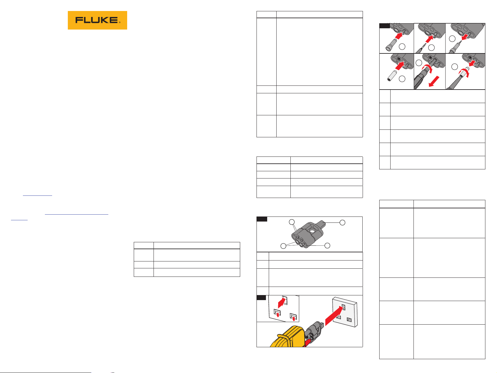
Figure 1 shows the Probe Tip Protector Cap. This
multifunctional accessory is useful for tests and
storage of different accessories.
Storage area for Probe Tip Sheaths
Storage area for 4 mm ∅ Probe Extensions
Earth-pin safety-socket opener for UK
sockets (press opener into socket to release
safety covers, see Figure 2)
Storage area for probes when not in use
C150 Zippered Soft Carrying Case
(sold separately)
Figure 3 illustrates how to store and retrieve the tip
accessories from the cap.
For storage, push Probe Tip Sheath into
place.
To retrieve, rmly push probe tip into Probe
Tip Sheath.
Pull on probe handle to remove Probe Tip
Sheath.
For storage, push 4 mm ∅ Probe Extensions
into place.
To retrieve, rmly push probe tip into Probe
Extensions. Twist 1/4 turn.
Pull on probe handle to remove Probe
Extensions. Continue to twist until tip is tight.
Quick Reference
Use the pushbuttons to turn the functions on or off.
See the list that follows for a quick reference to each
of these pushbuttons.
Pushbutton Description
c
I
h
cp
Il
Push to turn torch light on or off
(T110, T130, T150).
To save battery power the
function automatically turns off
after 30 seconds.
Push to hold the value that shows
in the LCD in volt and resistance
measurements. Push again to
turn HOLD off (T130, T150).
To save battery power the
function automatically turns off
after 30 seconds.
Push this button on each of
the probes at the same time to
start the test for low impedance
switchable load.
Push and hold for 2 seconds to
turn the beeper on or off. The
status shows on the LCD (T150,
T130) or with the LED (T110).
Push and hold for 2 seconds to
turn the resistance measurement
on or off (T150 only).
To save battery power, the
function automatically turns off
after 30 seconds.
Page 2
Features
4
5
Complies with EN 61243-3:2010
LED Indication Range: 12 V to 690 V dc and ac
V Display: Multiple LED Bargraph
Independent ELV indicator LED, indicates if >50 V ac/120 V dc is present even in
the event of no battery power or main circuit failure
LCD Indication Range: 6 V to 690 V dc and ac
V Display: Digital LCD 3½ digit (1 V resolution)
Resistance Measurement: LCD 3½ digit (0 to 1999 Ω/1Ω resolution)
LCD Backlight
Display HOLD: Freeze/unfreeze display with voltage or resistance measurement
CAT II 690 V / CAT III 600 V
CAT III 690 V / CAT IV 600 V
Rugged, Double-Insulated Wire
Fixed Impedance ~200 kΩ (~3.5 mA @ 690 V)
Switchable Load by 2 pushbuttons (30 mA @ 230 V)
Vibration During Load (when 2 switchable load pushbuttons are pushed)
Single-Pole Phase Test (also operates with gloves)
Rotary Field Direction (also operates with gloves)
Continuity Test / Diode Test
Torch
Beeper for Continuity/Phase/ACV (switchable)
Beeper for Continuity/Phase/ACV (nonswitchable)
IP54
IP64
Slim Metal Probe Tips (threaded base for included tip accessories)
Probe Tip Protector Cap (secure storage for the docked probes)
4 mm ∅ Probe Tip Thickness Extensions (for better t in outlets)
19 mm Probe Tip distance when docked
Probe Tip Sheath (UK GS38 sheath–keeps the exposed metal to a <4 mm limit)
Slim Probe for Ultra-Compact Form Factor
Model
T90 T110 T130 T150
• • • •
• • • •
• • • •
• • • •
• •
• •
•
• •
• •
•
• • •
• • • •
• • • •
• • •
• • •
• • • •
• • •
• • • •
• • •
• • •
•
•
• • •
• • • •
• • • •
• • • •
• • • •
• • • •
•
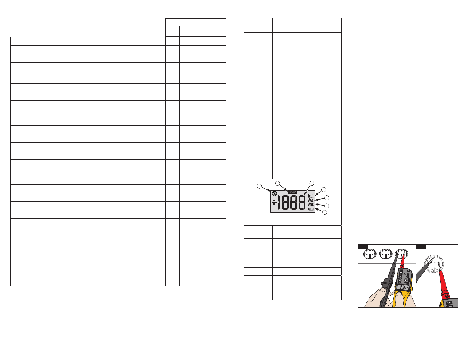
Display
LEDs
(All Models)
y
x
w
v
u
t
s
z
a
d
DC
e
b
M
f
g
q r
LCD
(T130/T150)
Description
Voltage level is backlit
Voltage level is more than ELV
limit (>50 V ac or >120 V dc)
Voltage is ac / phase in Single
Pole Phase test
Voltage is positive or negative at
the indicator probe
Battery is low / Replace battery
Silent mode (T110)
Continuity or diode in forward
operation
Switchable load is ON (two buttons
pressed and current ows)
3-phase sequence indication
detected left or right turning
phases with nonindicator probe
(L1) to indicator probe (L2)
1
2
Description
Silent mode (T130/T150)
Display is in HOLD mode
Voltage measurement (T130/T150)
or resistance measurement (T150)
Resistance measurement (T150)
AC Voltage measurement
DC Voltage measurement
Battery is low / Replace battery
How to Hold the Tester
Always hold the product behind the barrier to keep the
display in view. See Figure 4.
To prevent possible electric shock, never
touch the metal pins of the probes when
power is applied.
Warning
Self‑Test
The Tester has a built‑in self test function.
Before and after use, do a self-test:
1. Touch and hold the probe tips together.
f shows and you can hear the beeper (when
active on the T110/T130/T150). Or, in the
silent mode, the LED is on (when active on the
T110). This makes sure that the test leads have
continuity.
2. Make sure that:
• batteries are good
b (T90, T110) is NOT on
•
• B (T130, T150) does not show in the
display
3. Continue to hold the probe tips together for more
than three seconds.
4. Open the probe tips again. All LEDs (all but z and
g) must be on and all symbols in the LCD (T130,
3
4
5
6
7
gpn06.eps
T150) show for one second. This test makes sure
that all other internal circuits and indicators are
good.
5. Measure a known voltage such as a 230 V socket
outlet. This completes the self‑test and includes
the >ELV circuit.
If the Tester fails the self-test or voltage test, do not
use. See “Contacting Fluke” for service.
For an inspection of the insulation, cables, and case,
see Safety Information.
Page 3

Voltage Test
6 7
A voltage test is the main function of the Tester. The
T90 and T110 have an LED bargraph indication to
show the nominal voltage levels. The T130 and T150
also show the values in the LCD.
Connect the two test probes to the UUT to do a
voltage test.
Above 12 V the Tester turns on automatically. For the
T130 and T150, the LCD comes on at 6 V. The backlit
LEDs show the nominal voltage level, for example
v or w.
For the T130 and T150, the voltage is measured
and the value is shown on the LCD as for example,
227 j.
The voltage value on the LCD must not be used to
validate a zero voltage. Always use the LED bargraph.
For ac voltages, the
the LCD (T130/T150) illuminates. For dc voltages, the
polarity of the display voltage refers to the instrument
test probe with the D and E LEDs or the
symbol in the LCD (T130/T150). For voltages that
are more than the ELV limit (>50 V ac or >120 V dc),
z comes on in the display. The voltage LED
bargraph and the >ELV indicator must not be used for
measurements. For measurements you can use the
LCD on the T130/T150 to see the actual value.
a LED and the j symbol in
or -
+
Voltage Test with Switched Load, RCD
Trip Test (T110/T130/T150)
During voltage tests, you can decrease the
interference voltages from inductive or capacitive
coupling by loading the UUT with a lower impedance
than the Tester has in normal mode. In systems with
RCD circuit breakers, you can trip an RCD switch
with the same low impedance as when you measure
voltage between L and PE (see Figure 5).
To do an RCD trip test during voltage measurement,
push the two
10 mA or 30 mA RCDs between L and PE in a 230 V
system, it will trip.
During load current, the indicator probe side vibrates
and the
current. This indication is not to be used for voltage
test or measurement.
Due to low impedance, this circuit is overloadprotected and will decrease the load current after
20 seconds @ 230 V and after 2 seconds @ 690 V.
If the two pushbuttons are not used, the RCDs will not
trip, even in measurements between L and PE.
h buttons at the same time. If you have
g LED is the indication for the owing load
Single‑Pole Phase Test
To do a single-pole phase test:
1. Firmly hold the indicator probe around its body
(between the nger guard and cable).
2. Touch the probe tip to an unknown contact to nd
the conductor.
a turns on when the ac voltage is >100 V and
you hear the beeper (T110/T130/T150 only).
For a single‑pole phase test to nd external
conductors, the display function operates unreliably
in some conditions. An example is insulated body
protective equipment on insulated locations, such as a
PVC oor or berglass ladder.
The Tester operates without a touch electrode and is
usable when you wear gloves. The single‑pole phase
test is not meant to nd if a conductor is live or not.
For this function, always use the Voltage test.
Continuity/Diode Test
To do a continuity test of cables, switches, relays,
bulbs, or fuses:
1. Do a Voltage test to make sure the UUT is not live.
2. Connect the two test probes with the UUT. You will
hear the beeper if it is on (T110/T130/T150 only)
for continuity and
The test voltage/current polarity for a diode test at the
non-indicator test probe is positive + and the indicator
test probe is negative -.
The Tester automatically goes into the voltage
measurement mode if voltage is sensed.
Beeper (T110/T130/T150)
For Continuity, AC Voltage, and Single‑Pole Phase
Test modes, you can turn the beeper on or off:
1. Push and hold cp for 2 seconds to turn the
beeper on.
2. Push and hold cp for 2 seconds to turn the
beeper off.
The status shows together with Volt, Continuity, or
Single‑Pole Phase indications in the LED or LCD.
The beeper mode is stored until you change it. Always
do a continuity test (touch probe tips together) to
make sure that the beeper operates before you start
a test.
In work areas with high background noise, make sure
you can hear the beeper before you start a test.
f is on.
Note
Resistance Test (T150)
The Tester measures low ohm resistances between
1 Ω and 1999 Ω at a resolution of 1 Ω.
To do a resistance test:
1. Do a Voltage test to make sure the UUT is not live.
2. Connect the two test probes with the UUT. Push
and hold Il for 2 seconds and read value
on the display.
3. Push and hold Il for 2 seconds to turn the
function off.
To save battery power the function automatically
turns off after 30 seconds. The Tester automatically
goes into the voltage measurement mode if voltage
is sensed.
Display HOLD
(T130/T150)
The T130 and T150 include a Display HOLD function
for the LCD.
To use the Display HOLD function:
1. Push HOLD to freeze the LCD while in a Voltage
or Resistance measurement. The status is shown
in the display with a HOLD symbol.
2. Push HOLD again to unfreeze the LCD.
To save battery power the Display HOLD function
automatically turns off after 30 seconds.
Rotary Field Indication
(T110/T130/T150)
The Tester has a double‑pole rotary eld indicator.
The 3rd pole is capacitively-coupled into the unit from
the user’s hand. The Tester operates without a touch
electrode and is also usable when you wear gloves.
q and r display for ac voltage measurements,
but the rotary direction is found only in a three-phase
system. In parallel, the Tester reads the voltage
between two external conductors.
To use the rotary eld indicator:
1. Connect the test probe with the phase L1 and the
indicator probe with the phase L2.
2. Firmly hold the indicator probe around its body
(between the nger guard and cable).
The voltage and the rotary eld direction show on the
r (see Figure 6) signies that the supposed
display.
phase L1 is the actual phase L1 and the supposed
phase L2 is the actual phase L2 right rotary eld.
q (see Figure 7) signies that the supposed phase
L1 is the actual phase L2 and the supposed phase L2
is the actual phase L1 left rotary eld. A retest with
exchanged test probes will cause the opposite symbol
to illuminate.
Torch and Backlight
(T110/T130/T150)
The T110/T130/T150 include a torch and backlight
function. This function is helpful in areas with
unsatisfactory light, for example, division switch
cabinets.
To use the torch or backlight:
1. Push c to turn the torch and backlight on.
2. Push c again to turn the torch and backlight off.
To save battery power the function automatically turns
off after 30 seconds.
Maintenance
Warning
For safe operation and maintenance of the
product:
● Be sure that the battery polarity is correct to
prevent battery leakage.
● Remove batteries to prevent battery leakage
and damage to the Product if it is not used for
an extended period or if it is stored above or
below its operating temperature.
● Repair the Product before use if the battery
leaks.
Warning
To prevent personal injury:
● Batteries contain hazardous chemicals that
can cause burns or explode. If exposure to
chemicals occurs, clean with water and get
medical aid.
● Have an approved technician repair the
Product.
● Remove the input signals before you clean the
Product.
● Use only specied replacement parts.
● Keep the Tester dry and clean.
● Do not operate the Product with covers
removed or the case open. Hazardous voltage
exposure is possible.
Page 4

How to Clean
8
Before you clean the Tester, remove it from all
measurement circuits.
Caution
To prevent damage, do not use abrasives or
solvents on the Tester.
Clean the case with a moist cloth and weak detergent.
After you clean the Tester, do not use it for a period
of 5 hours.
When to Calibrate
Fluke recommends a calibration interval of 1 year.
Battery Replacement
If b (Fluke T90/T110) is on or B shows
in the LCD (Fluke T130/T150) during tests or
measurements, replace the batteries.
To replace the batteries:
1. Disconnect the Tester from the measurement
circuit.
2. Open the battery cover. See Figure 8.
3. Remove the discharged batteries.
4. Replace with two new 1.5V IEC LR03 AAA
batteries.
5. Align the battery polarity as shown on the case
housing.
6. Close and attach the battery cover.
Note
Do not overtighten the screw for the battery cover.
7. Complete a self‑test.
Specications
Model
T90 T110 T130 T150
LEDs
Voltage range 12 V to 690 V ac/dc
Resolution
Tolerance
Frequency range 0 / 40 Hz to 400 Hz
Response time ≤0.5 second
Auto power on ≥12 V ac/dc
LCD
Voltage range 6 V to 690 V ac/dc
Resolution ±1 V
Tolerance ±(3 % rdg + 5 digits)
Frequency range 0 / 40 Hz to 400 Hz
Response time ≤1 second
Auto power on ≥6 V ac/dc
Voltage detection Automatic
Polarity detection Full range
Range detection Automatic
Internal basic load impedance
Peak current
Operation time
Recovery time
Switchable Load ~7 kΩ
Peak current Is (load) = 150 mA
RCD tripping I~30 mA @ 230 V
Continuity Test 0 to 400 kΩ
Accuracy nominal resistance +50 %
Test current ≤5 µA
Single-pole Phase Test 100 V ac to 690 V ac
Frequency range
Rotary Field Indication
Voltage range (LEDs)
Frequency range 50 Hz to 60 Hz
Resistance Measurement 0 Ω to 1999 Ω
Resolution 1 Ω
Tolerance
Temperature coefcient ±5 digits / 10 K
Test current ≤30 µA
Size in mm (HxWxL) 245x64x28 255x78x35
Weight in kg (includes batteries) 0.18 0.27
±12 V, 24 V, 50 V, 120 V,
230 V, 400 V, 690 V
Complies with
EN 61243-3:2010
Maximum 3.5 mA at
690 V 200 kΩ / Is <3.5 mA
(no RCD tripping)
Duration Time =
30 seconds
Recovery Time =
240 seconds
40 Hz to 60 Hz
50 Hz to 400 Hz
100 V to 690 V
(phase to earth)
±(5 % rdg +10 digits) @
20 °C
• • • •
• • • •
• • • •
• • • •
• • • •
• • • •
• • • •
• • • •
• • • •
• • • •
• • • •
• • • •
• • •
• • •
• • •
• • • •
• • • •
• • • •
• • • •
•
• • •
• • •
• • •
• • •
• •
• •
• •
• •
• •
• •
Environmental
Pollution degree .......................2
Protection degree .....................IP54 (T90)
Operating Temperature ............-15 °C to +45 °C
Storage Temperature ................-20 °C to +60 °C
Humidity ...................................85 % RH maximum
Altitude .....................................2000 m
Vibration ...................................refer to EN61243-3
Safety EN61243-3:2010
Transporting goods...................VBG 1, § 35
Overvoltage protection .............690 V ac/dc
Measurement category
T90......................................CAT II 690 V
T110/T130/T150 .................CAT III 690 V
Power supply ...............................2 x 1.5 V Micro /
Power consumption ....................50 mA maximum /
Language support .......................Czech, Dutch,
IP64 (T110/T130/
T150)
CAT III 600 V
CAT IV 600 V
LR03 / AAA
~250 mW
English, Finnish,
French, German,
Italian, Norwegian,
Polish, Portuguese,
Romanian,
Russian, Spanish,
Swedish, Turkish
LIMITED WARRANTY & LIMITATION OF
LIABILITY
This Fluke product will be free from defects in material and
workmanship for two years from the date of purchase. This
warranty does not cover fuses, disposable batteries, or damage
from accident, neglect, misuse, alteration, contamination, or
abnormal conditions of operation or handling. Resellers are not
authorized to extend any other warranty on Fluke’s behalf. To
obtain service during the warranty period, contact your nearest
Fluke authorized service center to obtain return authorization
information, then send your defective Tester to that Service
Center with a description of the problem. Replace depleted
batteries immediately to avoid Tester damage from battery
leakage.
THIS WARRANTY IS YOUR ONLY REMEDY. NO OTHER
WARRANTIES, SUCH AS FITNESS FOR A PARTICULAR
PURPOSE, ARE EXPRESSED OR IMPLIED. FLUKE IS NOT
LIABLE FOR ANY SPECIAL, INDIRECT, INCIDENTAL OR
CONSEQUENTIAL DAMAGES OR LOSSES, ARISING FROM
ANY CAUSE OR THEORY. Since some states or countries do
not allow the exclusion or limitation of an implied warranty or of
incidental or consequential damages, this limitation of liability
may not apply to you.
Fluke Corporation Fluke Europe B.V
•
•
•
P.O. Box 9090 P.O. Box 1186
Everett WA 98206‑9090 5602 B.D.
Eindhoven
The Netherlands
11/99
•
•
 Loading...