

Page 1
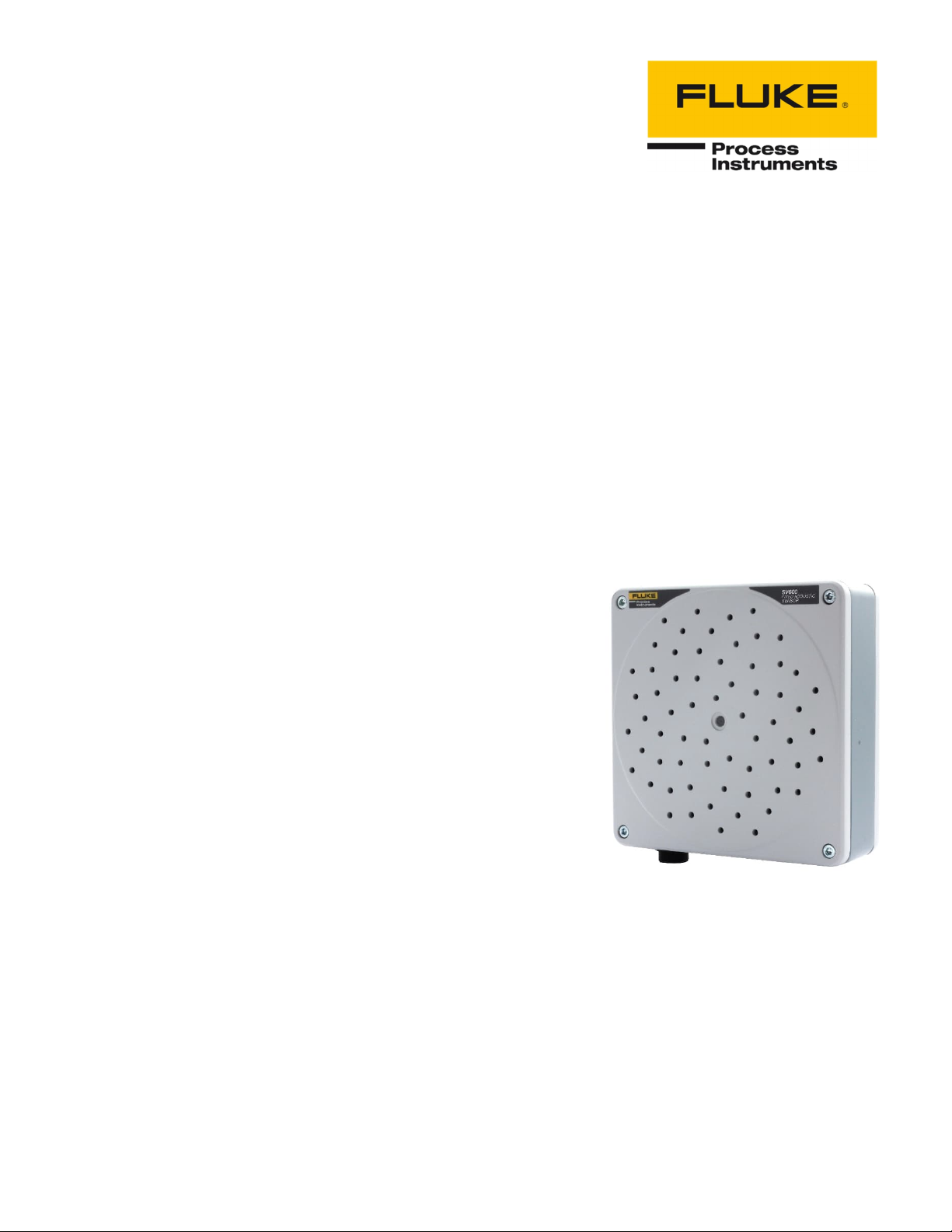
SV600 Series
Sonic Viewer
Users Manual
PN 5306246, English, Rev. 2.3, Jun 2022
© 2022 Fluke Process Instruments. All rights reserved. Printed in Germany. Specifications subject to change without notice.
All product names are trademarks of their respective companies.
Page 2

Warranty
The manufacturer warrants this instrument to be free from defects in material and workmanship under normal use
and service for the period of two years from date of purchase. This warranty extends onl y to the original purchaser.
This warranty shall not apply to fuses, batteries or any product which has been subject to misuse, neglect, accident,
or abnormal conditions of ope ration.
In the event of failure of a product covered by this warranty, the manufacturer will repair the instrument when it is
returned by the purchaser, freight prepaid, to an authorized Service Facility within the applicable warranty period,
provided manufacturer’s examination discloses to its satisfaction that the product was defective. The manufactu rer
may, at its option, replace the product in lieu of repair. With regard to any covered product returned within the
applicable warranty period, repairs or replacement will be made without charge and with return freight paid by the
manufacturer, unless the failure was caused by misuse, neglect, accident, or abno rmal conditions of operation or
storage, in which case repairs will be billed at a reasonable cost. In such a case, an estimate will be submitted
before work is started, if requested.
The foregoing warranty is in lieu of all other warranties, expressed or implied, including but not limited to any
implied warranty of merchantability, fitness, or adequacy for any particular purpose or use. The manufacturer shall
not be liable for any special, incidental or consequential dama ges, whether in contract, tort, or otherwise.
This manual is available in different languages. In case of differences be tween the language versions , the
English manual is binding.
Page 3

Table of Contents
Chapter Page
TABLE OF CONTENTS .......................................................................................................................................... 3
LIST OF FIGURES ................................................................................................................................................ 4
SAFETY INFO RMATION ......................................................................................................................................... 6
CONTACTS ........................................................................................................................................................ 9
1 DESCRIPTION ................................................................................................................................................ 10
1.1 Features .......................................................................................................................................................................................................... 10
1.2 Available Models ............................................................................................................................................................................................. 10
1.3 System Overview ............................................................................................................................................................................................ 11
2 TECHNICAL DATA .......................................................................................................................................... 12
2.1 Physical Properties.......................................................................................................................................................................................... 12
2.2 System Integration .......................................................................................................................................................................................... 12
2.3 Camera ............................................................................................................................................................................................................ 12
2.4 Microphones .................................................................................................................................................................................................... 12
2.5 General ............................................................................................................................................................................................................ 12
3 ENVIRONEMENT ............................................................................................................................................. 13
3.1 Ambient Temperature ..................................................................................................................................................................................... 13
3.2 Protection ........................................................................................................................................................................................................ 13
4 INSTALLATION ............................................................................................................................................... 14
4.1 System Requirements ..................................................................................................................................................................................... 14
4.2 Connecting a SV600 ....................................................................................................................................................................................... 14
4.2.1 Mode 1: Connect to a Network using DHCP ......................................................................................................................................... 14
4.2.2 Mode 2: Connect directly to a PC/Laptop using Auto IP ....................................................................................................................... 15
4.2.3 Mode 3: Connect to a Network using Static IP ...................................................................................................................................... 15
4.2.4 Mode 4: Connect to a to a PC/Laptop using Static IP ........................................................................................................................... 15
4.3 Setting Up SV600 ............................................................................................................................................................................................ 15
4.4 Performing a Firmware Update ....................................................................................................................................................................... 18
4.5 LED Indicator ................................................................................................................................................................................................... 19
4.6 Mounting .......................................................................................................................................................................................................... 19
4.6.1 VESA Mounting ...................................................................................................................................................................................... 20
4.6.2 Tripod Mounting ..................................................................................................................................................................................... 20
4.6.3 Mounting Distance ................................................................................................................................................................................. 20
5 SV600 DASHBOARD ...................................................................................................................................... 21
5.1 Home Page ..................................................................................................................................................................................................... 21
5.2 Insight Pages ................................................................................................................................................................................................... 22
5.2.1 Sensor SPL ............................................................................................................................................................................................ 22
Page 4

5.2.2 Events ..................................................................................................................................................................................................... 23
5.3 Streaming Page ............................................................................................................................................................................................... 24
5.4 Device Configuration Pages ............................................................................................................................................................................ 25
5.4.1 User Management .................................................................................................................................................................................. 25
5.4.2 Networking .............................................................................................................................................................................................. 25
5.4.3 Date and Time ........................................................................................................................................................................................ 26
5.4.4 Device Information.................................................................................................................................................................................. 27
5.4.5 Device Maintenance ............................................................................................................................................................................... 28
5.5 Management Pages......................................................................................................................................................................................... 29
5.5.1 Measurements ........................................................................................................................................................................................ 29
5.5.2 SoundMap .............................................................................................................................................................................................. 30
5.5.3 Events ..................................................................................................................................................................................................... 31
5.5.4 Inputs/Outputs ........................................................................................................................................................................................ 32
5.5.5 Subscriptions .......................................................................................................................................................................................... 33
5.5.6 Actions .................................................................................................................................................................................................... 34
5.6 API Documentation .......................................................................................................................................................................................... 34
5.7 Setting up a SoundMap Event Trigger on a Wago Unit .................................................................................................................................. 35
6 TROUBLESHOOTING ....................................................................................................................................... 37
6.1 How to check device health / when to request a new device, since too broken? ........................................................................................... 37
6.2 Stream page does not show SoundMap overlay or spectrum ........................................................................................................................ 37
6.3 I set a certain reporting interval, but data is returned at a slower rate ............................................................................................................ 37
6.4 How do I restart my device without removing power....................................................................................................................................... 37
List of Figures
Figure Page
Figure 1-1: SV600 Sonic Viewer .................................................................................................................................................................................. 10
Figure 1-2: System Overview....................................................................................................................................................................................... 11
Figure 4-1: Vesa 100 Mounting .................................................................................................................................................................................... 20
Figure 4-2: Tripod Mounting ......................................................................................................................................................................................... 20
Page 5
Compliance Statement
The device complies with the requirements of the European Directives:
EC – Directive 2014/30/EU – for Electromagnetic compatibility directive (EMC)
EC – Directive 2011/65/EU – RoHS3 Restriction of Hazardous Substances
EN 61000-6-3:2007+A1:2011
EN 61000-6-2:2005 + AC:2005
EU2011/65/EU RoHS2
EU2015/863
Page 6

Safety Information
This document contains important information, which should be kept at all times with the instrument during its
operational life. Other users of this instrument should be given these instructions with the instrument. Eventual
updates to this information must be added to the original document. The instrument can only be operated by trained
personnel in accordance with these instructions and local safety regulations.
Acceptable Operation
This instrument is intended only for the measurement of acoustic signals. The instrument is appropriate for
continuous use. The instrument operates reliably in demanding conditions as long as the documented technical
specifications for all instrument components are adhered to. Compliance with the operating instructions is
necessary to ensure the expected results.
Unacceptable Operation
The instrument should not be us ed for medical diagnosis.
Replacement Parts and Accessories
Use only original parts and accessories approved by the manufacturer. The use of other products can compromise
the operation safety and functionality of the instrument.
Page 7
Safety Symbol
Description
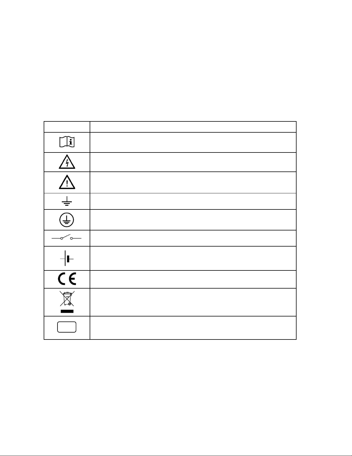
Read all safety information before in the handbook
IP
54
Hazardous voltage. Risk of electrical shock.
Warning. Risk of danger. Important information. See manual.
Earth (ground) terminal
Protective conductor terminal
Switch or relay contact
DC power supply
Conforms to European Union directive.
Disposal of old instruments should be handled according to professional and
environmental regulations as electronic waste.
International Ingress Protection Marking
Page 8

To prevent possible electrical shock, fire, or personal injury follow these guidelines:
Read all safety information before you use the product.
Use the product only as specified, or the protection supplied by the product can be
compromised.
Do not use the product around explosive gases, vapor, or in damp or wet environments.
Carefully read all instructions.
Do not use and disable the product if it is damaged.
Do not use the product if it operates incorrectly.
Do not apply more than the rated vol tage between the terminals or each terminal and earth
ground.
Incorrect wiring can damage the se nsor and void the warranty. Before applying power, make
sure all connections are correct and secure!
To prevent possible electrical shock, fire, or personal injury make sure that metallic components
are grounded before use.
Have an approved technician repai r the product.
Page 9

Contacts
Fluke Process Instruments
America
Everett, WA USA
Tel: +1 800 227 8074 (USA and Canada, only)
+1 425 446 6300
EMEA
Berlin, Germany
Tel: +49 30 478 0080
China
Beijing, China
Tel: +86 10 6438 4691
Technical Support
USA & Canada +65 67995578
Europe +49 30478008444
Latin America +1 831 458 3900
Australia & New Zealand +1 831 458 3900
Asia
Singapure +65 67995578
Japan +81 3 6714 3114
India +65 67995578
China +86 1064384691
www.flukeprocessinstruments.com
© Fluke Process Instruments
Specifications subject to change without notice.
Page 10
SV600Series
Users Manual, Rev. 2.3, Jun 2022
1 Description
The SV600 sonic viewer is the evolution in acoustic monitoring solutions. It combines the powerful use of acoustic
imaging, detection of sound levels and accurate localization. The SV600 sonic viewer supports edge computing,
all powered and connected with one single network cable.
The SV600 sonic viewer can be used in a variety of application fields: safety & security, mobility, environmental
and machine maintenance. The acoustic monitors can be easily connected to cover larger areas with secure and
GDPR proof data handling.
1.1 Features
All in one acoustic monitoring
Environmental noise monitoring
Visual light camera integrated
Sound intensity mapping
Figure 1-1: SV600 Sonic Viewer
10
1.2 Available Models
SV600-1 providing:
64 MEMS microphones
Sunflower Array
Integrated VIS camera
dB Values
Localization
Page 11
1
1.3 System Overview
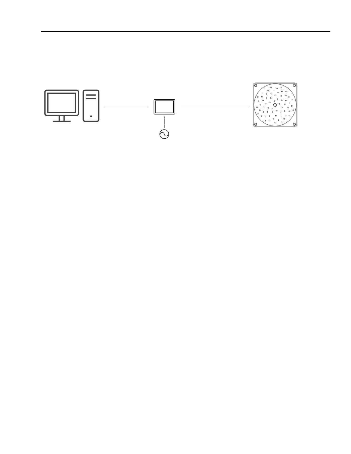
Figure 1-2: System Overview
PoE Injector
Ethernet
Description
System Overview
Power over Ethernet (PoE)
VAC
Sonic Viewer
11
Page 12

SV600Series
Users Manual, Rev. 2.3, Jun 2022
2 Technical Data
2.1 Physical Properties
Size (LxWxD) 170 x 170 x 65 mm (6.7 x 6.7 x 2.5 in)
Weight 0.85 kg (1.8 lb)
Power PoE+ port 100 – 240V AC, max 37 W, IEEE 802.3
Status LED red, green
2.2 System Integration
API HTTP REST, Modbus
Event Triggers dB SPL or SoundMap threshold
Event Actions Acoustic SoundMap overlay
2.3 Camera
Type Integrated visible light
Resolution video 720 x 1280
Aspect ratio 4:3
Camera Resolution 720p at 30 fps
2.4 Microphones
Type MEMS, Digital Bottom Port
SNR 64 dB for 94 dB SPL, @ 1kHz, (A-weighted, at 1 kHz)
Sensitivity -26 dBFS ± 1.5 dB, at 1 kHz, 94 dB SPL
Acoustic Overload Point 120 dB SPL, at 1 kHz, <10% THD
2.5 General
Ingress Protection IP54
Operating Temperatures -20 to 50°C (4 to 122°F)
12
Page 13

Environement
3
Ambient Temperature
3 Environement
3.1 Ambient Temperature
The SV600 is designed for ambient operating temperatures between -20 to 50°C (4 to 122°F). It is necessary to
verify the environmental temperature and install the housing at the correct distance from the heating source. Note
that too cold water can cause condensation, which can lead to damage in the device, the ambient operating relative
humidity is between 10 – 100% RH (non-condensing).
3.2 Protection
The SV600 complies with the international protection standard IP54. Please be aware that the SV600 is not
watertight but splash-proof, the effectiveness against splashing under IP54 is possible only if the device is
inspected periodically to all seals of the waterproof connectors.
13
Page 14

SV600Series
Users Manual, Rev. 2.3, Jun 2022
4 Installation
The SV600 series is an IP based device. A good reliable ne twork and power infrastructure is the backbone of every
IP based solution, and the same applies to the SV600 acoustic monitor. In the installation you will first find the
minimum requirements we prescribe to have the best operating experience with the SV600 acoustic monitor.
4.1 System Requirements
1. Power: The SV600 is powered via Power over Ethernet PoE+ (IEEE 802.3at-200). Only one Cat5e or
Cat6 network cable is needed for connecting a listener. The SV600 uses around 20 W of power. The
power can be provided either via a PoE switch or a separate PoE injector to the SV600.
2. Connection (Wired): The SV600 can be connected to the network via one Cat5e or Cat6 network cable.
In case of a fiber optic network a fiber to copper converter needs to be used to connect the SV600 to the
network.
3. Connection (Wireless): In case of a wireless network requirement, the SV600 can be connected to the
network using a Wifi, 4G or 5G router.
4. Throughput: The SV600 uses about 7 MBit/s of data. (Note: the value is likely to be updated in the future)
5. Internet: The SV600 does not need an active internet connection to function.
6. Stability: SV600 device is able to recover from network failures. However, if a network is down for a
longer ti me, data might get dropped. The SV600 buffers all data for at least 30 s. This data can
retroactively be retrieved.
7. Broadcast/Multicast messages: The network on which the SV600 devices are connected, has to
support (or not block) broadcast messages. Broadcast messages from the SV600 are used to find them
(mDNS protocol, zeroconf). The ZeroConf uses the following IP address: 224.0.0.251. Alternatively, the
user can configure static IP to reach the unit, mDNS is not required then.
8. Used Ports: Communication to a SV600 device is handled via ports 80, 443, 9011, 9012 and 9013.
4.2 Connecting a SV600
There are several modes in which you can connect a SV600:
1. Mode 1: Connect to a Network using DHCP
2. Mode 2: Connect directly to a PC/Laptop using Auto IP
3. Mode 3: Connect to a Network using Static IP
4. Mode 4: Connect directly to a PC/Laptop using Static IP
Note
When you get a new SV600 device, it is configured so it can be connected in both mode 1 and 2 without any
additional configuration.
If you want to configure the SV600 to connect it in mode 3 or 4, you will first need to connect it in mode 1 or
2 and change the configuration of the SV600 via the dashboard as explained in section 4.3 Setting Up
SV600, page 15.
14
Note
To power the SV600, you need a PoE injector or PoE capable switch. The PoE switch detects if a device
needs PoE or not. The requi rement is PoE+ for the SV600.
4.2.1 Mode 1: Connect to a Network using DHCP
In mode 1, connect the SV600 to a network which has a DHCP server available. Typically, the router of your
network runs a DHCP server, but this can also run in a server computer. Contact your network administrator for
more information about your particular network setup.
Page 15

Installation
4
Setting Up SV600
Connection can be made in two ways:
1. Connect the SV600 directly to a suitable PoE capable switch that is connected to the network
2. Connect the SV600 via a suitable PoE injector to a non-PoE capable switch that is connected to the
network
The DHCP server will then automatically provide an available IP address to the SV600 in the address range that
the network administer has configured. The devices that can communicate with the SV600 (e.g. your PC/Laptop)
need to be connected to the same network, either via a wired connection or a wireless access p oint.
4.2.2 Mode 2: Connect directly to a PC/Laptop using Auto IP
In mode 2, connect the SV600 directly to a PC or Laptop.
Since ethernet ports on a PC/Laptop are (almost) never PoE capable, you will require a suitable PoE injector.
Connection can be made in two ways:
1. Connect the SV600 via a suitable PoE injector to a free ethernet port on your PC/Laptop
2. Connect the SV600 via a suitable PoE injector to an ethernet-usb dongle plugged into your PC/Laptop
The SV600 will assign itself an IP address in the 169.254.0.0/16 range, also known as the Auto IP range.
4.2.3 Mode 3: Connect to a Network using Static IP
In mode 3, connect the SV600 to any network (with or without DHCP server).
Connection can be made in two ways:
1. Connect the SV600 directly to a suitable PoE capable switch that is connected to the network
2. Connect the SV600 via a suitable PoE injector to a non-PoE capable switch that is connected to the
network
A manually determined, fixed IP address can be assigned to the SV600 via the Dashboard.
Note
Manually setting a static IP Address wrongly can lead to the d evice becoming unreachable. Make sure you
configure the device correctly or ask your network administrator for help.
4.2.4 Mode 4: Connect to a to a PC/Laptop using Static IP
Since ethernet ports on a PC/Laptop are (almost) never PoE capable, you will require a suitable PoE injector.
Connection can be made in two ways (note ‘+’ devices require PoE+):
1. Connect the SV600 via a suitable PoE injector to a free ethernet port on your PC/Laptop
2. Connect the SV600 via a suitable PoE injector to an ethernet-usb dongle plugged into your PC/Laptop
A manually determined, fixed IP address can be assigned to the SV600 via the Dashboard.
Note
Manually setting a static IP Address wrongly can lead to the d evice becoming unreachable. Make sure you
configure the device correctly or ask your network administrator for help.
4.3 Setting Up SV600
Before you start:
Make sure the SV600 is connected with your PC/Laptop in either mode 1 or mode 2 as described in
section 4.2 Connecting a SV600, page 14.
Wait until the indicator light (on the side of the SV600) becomes solid green.
15
Page 16
SV600Series
Users Manual, Rev. 2.3, Jun 2022
Step 1
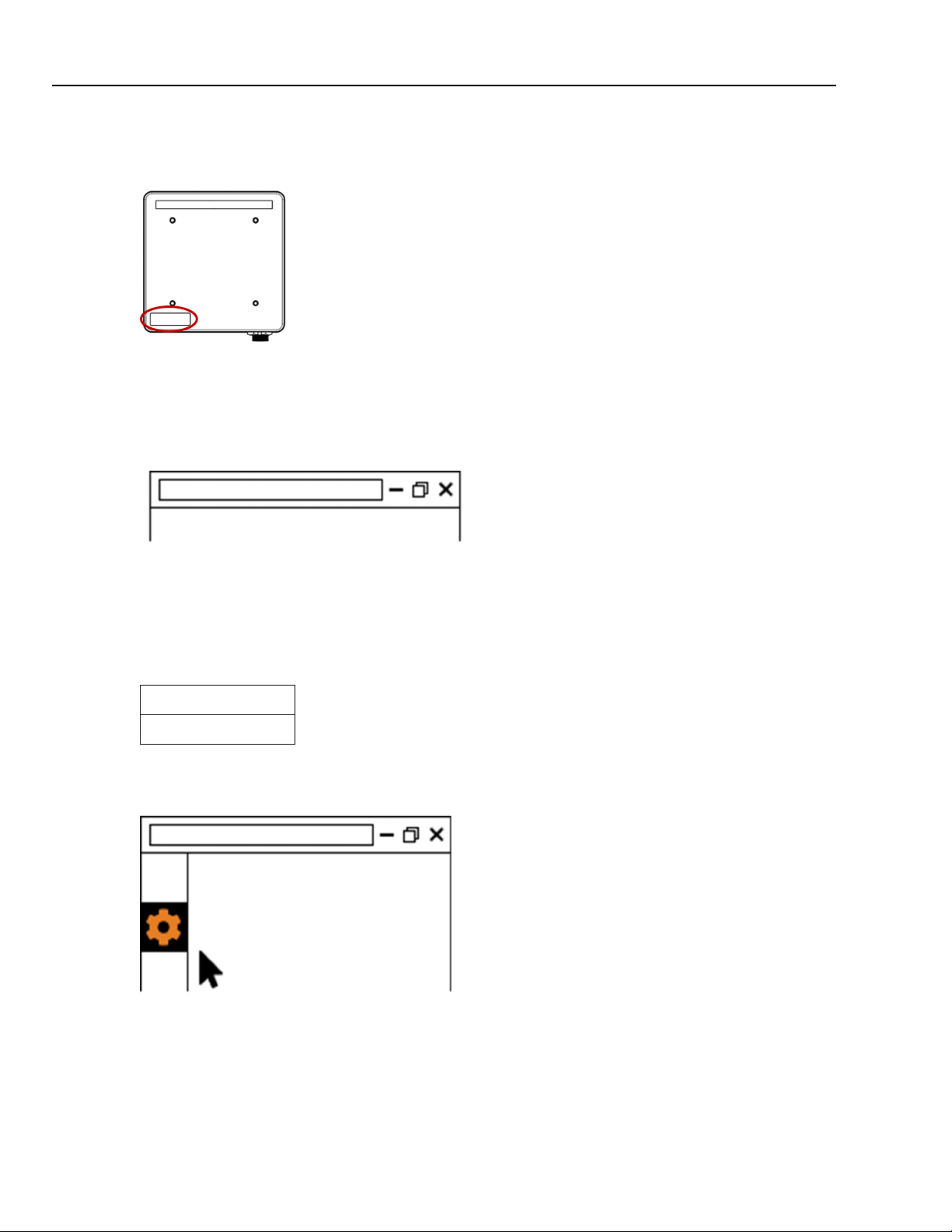
Keep the serial number of the SV600 ready. The serial number can be found on the back of the device at the
bottom-left.
Step 2
Open your web browser (Chrome, Firefox, Edge, Safari).
Step 3
Type http://<serial number> in your address bar. E.g. http://100110001
http://100110001
If your network does not have DNS server or if you connected the device directly to your PC add .local at the end
of the serial number address. e.g. http:// 100110001.local
Step 4
Your browser will now show the device dashboard and prompt you to login. The default credentials are:
Username: admin
Password: admin
Step 5
In the device dashboard go to the “Device Configuration” page and click on Device Information
http://100110001
16
Page 17
Setting Up SV600
4
http://100110001
http://100110001
Step 6
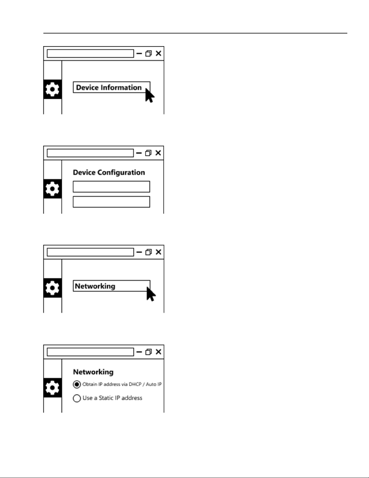
Set the device coordinates and relevant installation information such as angles and target distances (if known)
http://100110001
Installation
Step 7
Go back to the “Device Configuration” page and click on Networking.
http://100110001
Step 8
In the Network page set the preferred network settings according to your project.
Select “Obtain IP address via DHCP / Auto IP” (the default) if you want to run the SV600 in either mode 1 or 2 as
described in section 4.2 Connecting a SV600, page 14. No additional configuration is required.
17
Page 18

SV600Series
Users Manual, Rev. 2.3, Jun 2022
Select “Use a Static IP address” if you want to run the SV600 in either mode 3 or 4 as described in section
4.2 Connecting a SV600, page 14. You will need to specify the following:
IP address: The static IP address that the SV600 should use
Subnet mask: The subnet mask of the network the SV600 is (going to be) connected to
Gateway: The gateway address of the network the SV600 is (going to be) connected to
Primary and Secondary DNS Address: The IP addresses of the primary and secondary DNS server on
the network.
After the device has been configured, you will need to reload your browser window since the IP address of the
SV600 has changed. Depending on your network setup and the values you have entered, you might also need to
change the configuration of your network adapter before you can reach the SV600 again. Ask your network
administrator for assistance.
Currently all values need to be specified. If you do not need one of the values, just leave it at the default
Manually setting a static IP Address wrongly can lead to the d evice becoming unreachable. Make sure you
Note
setting. If you don’t know what thes e settings mean, contact your network administrator.
Note
configure the device correctly or ask your network administrator for help.
4.4 Performing a Firmware Update
Before you start:
The following steps assume you have already completed the device setup as described in section 4.3 Setting Up
SV600, page 15, and can access the device dashboard.
Step 1
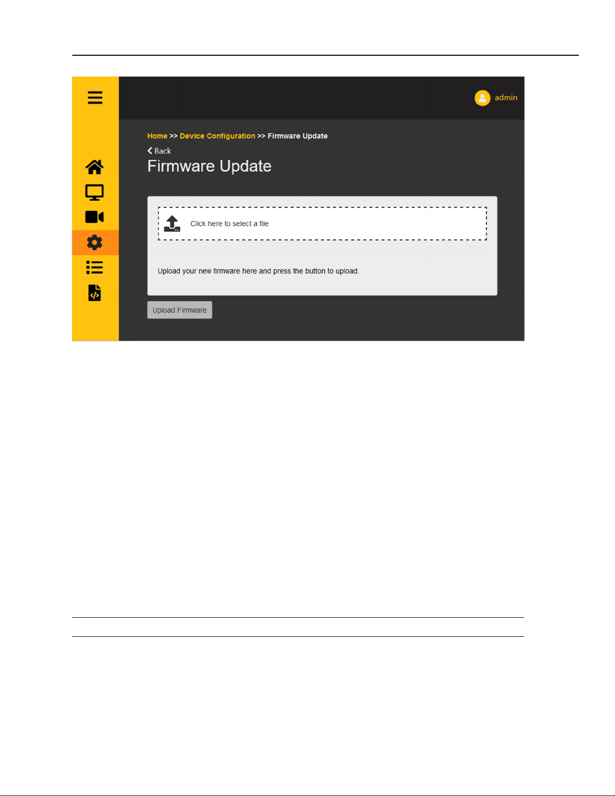
In the device dashboard go to the “Device Configuration” page and click on Firmware Update.
Step 2
On the Firmware Update page, click “Click here to select a file”. A file selection menu will appear.
18
Page 19
Installation
4
LED Indicator
Step 3
Select the firmware file from the file selection menu and click “Open”.
Step 4
Click “Upload Firmware”. A popup window will appear asking you to confirm, click “OK”.
Step 5
First, the file will be uploaded to the device. The progress bar indicates the progress of the upload.
Second, the device will install the new firmware, this can take between 1 and 5 minutes. The progress bar will keep
animating during this process.
When the firmware update is complete, the progress bar turns green. The device will now be reset. Wait until the
LED on the device turns green again, then refresh the dashboard and you can start using the device with the new
firmware. In rare cases, a firmware update might fail. If it still fails after a retry or two, contact your supplier.
4.5 LED Indicator
The LED indicator is a small semi-transparent dot (powered off) on the side of the device.
Colour: state: Function
Red Solid Starting or error state
Green Solid Ready
4.6 Mounting
SV600 has several ways to be placed in the environment.
19
Page 20
SV600Series
Users Manual, Rev. 2.3, Jun 2022
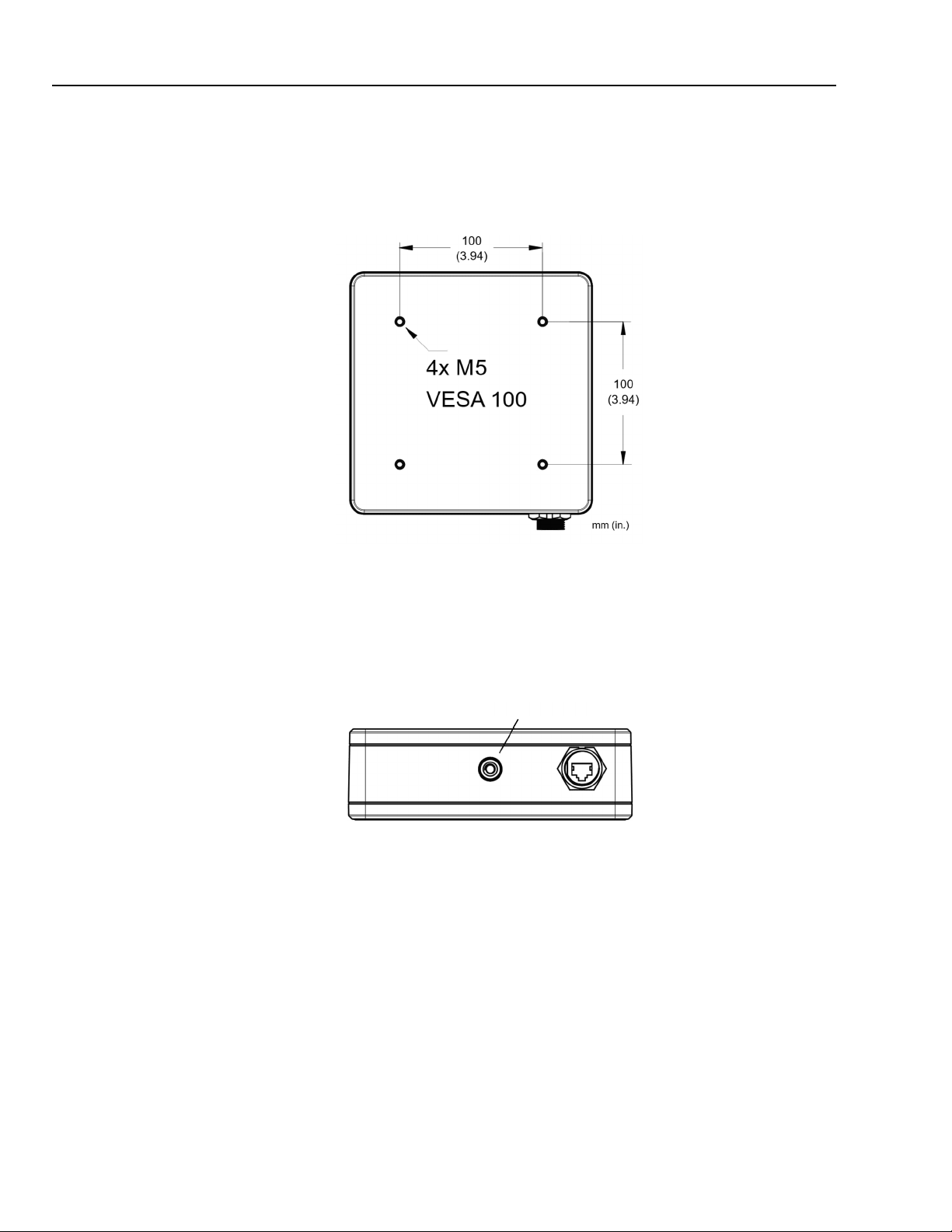
4.6.1 VESA Mounting
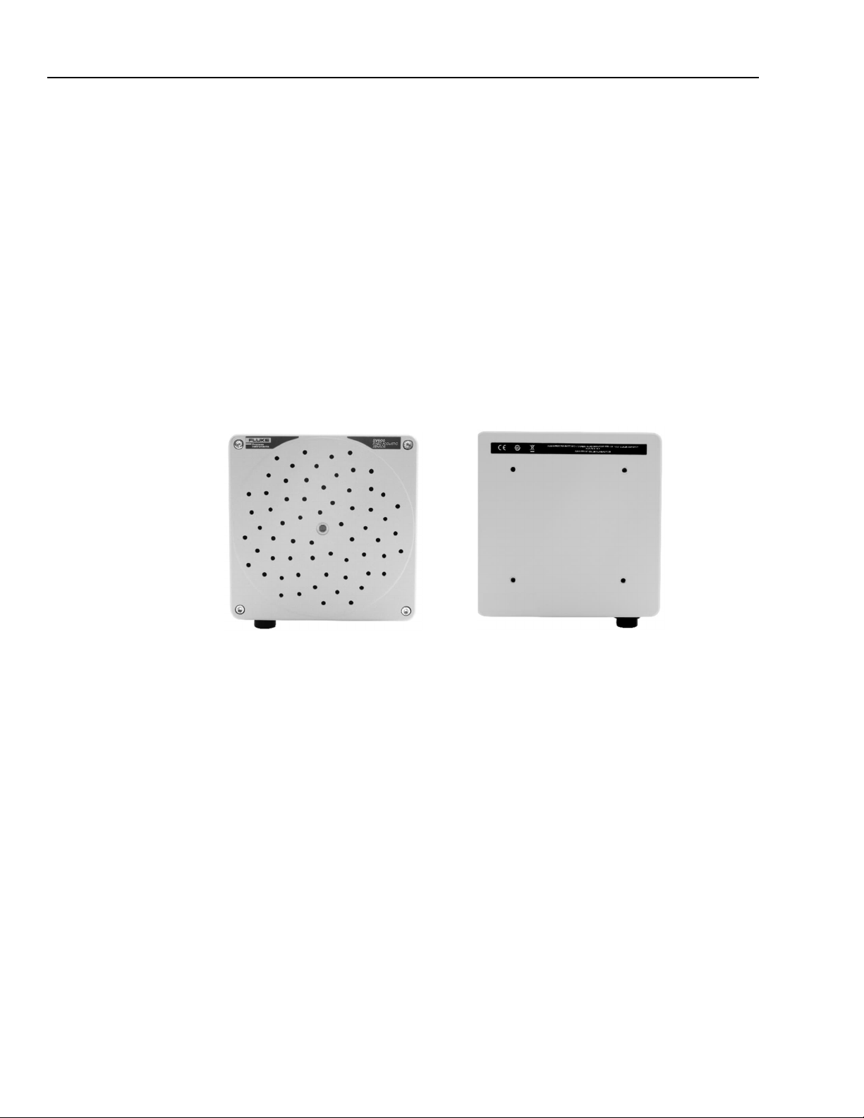
SV600 provides a Vesa 100 mounting on the back of the unit.
Figure 4-1: Vesa 100 Mounting
4.6.2 Tripod Mounting
SV600 provides a tripod mounting on the side of the unit.
Figure 4-2: Tripod Mounting
4.6.3 Mounting Distance
The mounting distance is depending on your situation and differs from area to area. In general, the distance to the
area being measured should be:
Minimum of 3 m (9.8 ft).
Maximum of 15 m (49.2 ft).
Outside of these bounds the system will not be able to properly monitor the whole area.
Inside of these bounds, the area that can be monitored approximately equals twice the mounting distance.
o Example: a SV600 mounted at 6 m (20 ft) high can cover an area of 12 x 12 m (40 x 40 ft).
20
Note
No other holes should be drilled in the housing as this will affect the water-resistance capabilities of the
device or worse damage the electrical components inside..
Page 21
SV600 Dashboard
5
Home Page
5 SV600 Dashboard
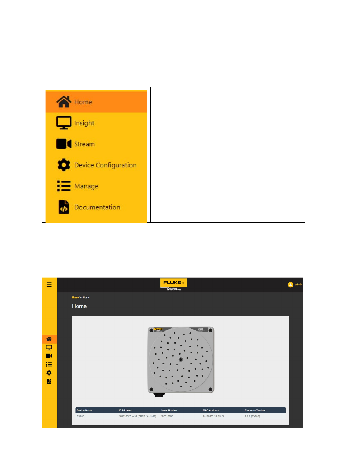
SV600 devices have (almost) all functionality visible on the dashboard. All functions provided via the dashboard
are also available by directly using the API. Use the navigation menu to the left to go the following pages:
Home
Insight
Streaming
Device Configuration
Management
(API) Documentation
5.1 Home Page
Providing the basic information of the selected device; name/tag, IP address, Serial number, MAC address and
Firmware version.
21
Page 22
SV600Series
Users Manual, Rev. 2.3, Jun 2022
5.2 Insight Pages
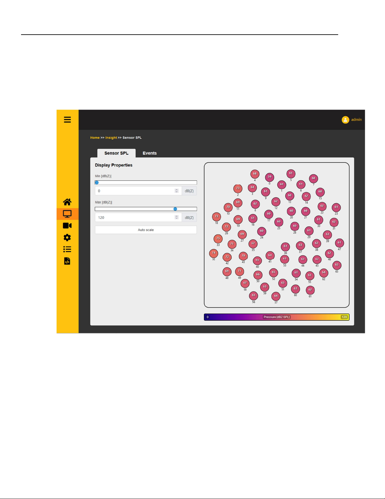
5.2.1 Sensor SPL
Out of the box, on this page the so und pressure level of every single channel is measured in dB(Z) and displayed
respectively. You can easily check if there is any abnormality coming from any of the micro phone channels using
this page. If one or a few microphones always display different values, they might be faulty.
22
Use the Min slider or input box to se a minimum value. Any value below this value will be colored dark
purple
Use the Max slider or input box to set a maximum value. Any value above this value will be colored bright
yellow
Auto scale will reset the min/max values to scale with the data coming from the device at the moment the
button is pressed
Page 23
SV600 Dashboard
5
Insight Pages
5.2.2 Events
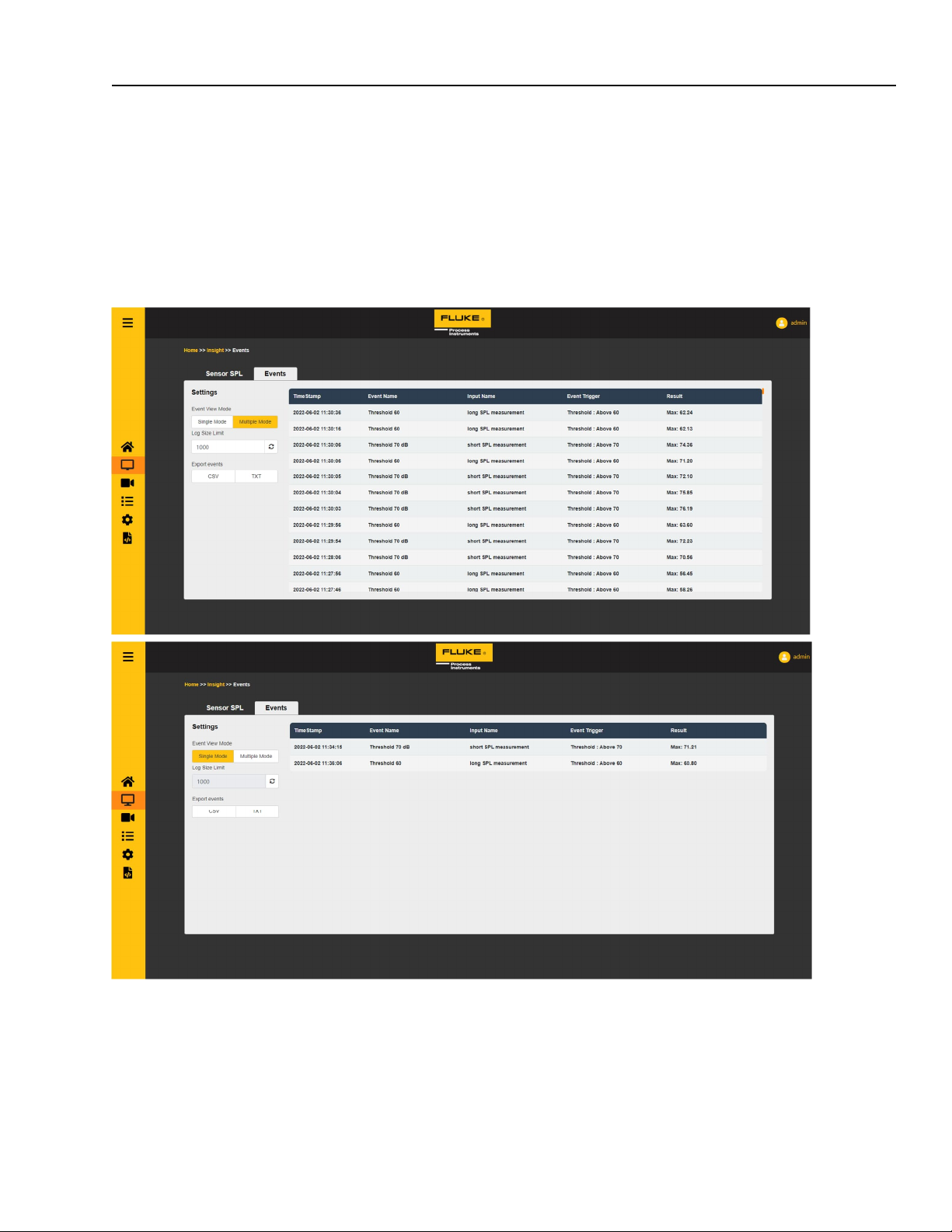
Events are triggers that can be set to an SPL threshold or classification/anomaly detection. This page will log and
display when this occurred.
A list of events is displayed acompied by their respective timestamps, event name, name of the input measurement,
trigger conditions and result of the event. This list can be shown in Multiple Mode, showing all triggered events, or
Single Mode, which displays only the last occurrence of each different event. The difference is shown below.
Use the Log Size Limit input box to set how many event to display on the right.
Use the CSV button export to export the events in “.csv” format or the TXT button for “.txt” format. The
number of events is the Log Size.
23
Page 24
SV600Series
Users Manual, Rev. 2.3, Jun 2022
5.3 Streaming Page
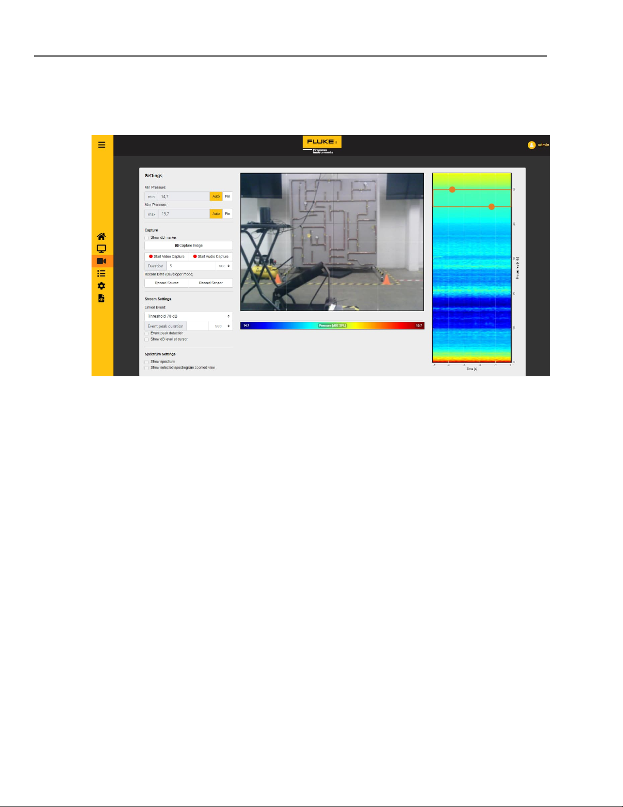
Using the spectrogram live feed (to the right on the image below), a user can see in which frequency bands the
most sound is detected. Red colors represent high intensity, blue colors represent low intensity.
The user can drag the frequency band to use a different band or make it smaller/larger by dragging the
orange circles. The minimum frequency range is 2000 Hz wide and the maximum frequency selection is
8000 Hz wide.
The min/max values can be pinned by clicking “Pin”. They can then be set by the user
The min/max values can be automatically rescaled by clicking “Auto”. They will then rescale
automatically to best visualize the sound sources
Capture Image: will capture an image of the current SoundSurface™ including min/max values and
spectrogram.
Start Video Capture: will start recording a video from the video stream. The video will stop when the
specified duration is over, or the “Sto p Video Capture” button i s pressed.
Start Audio Capture: will start a full range recording from the audio stream. The recording will stop when
the specified duration is over, or the “Stop Audio Capture” button is pressed.
Linked Event and peak detection: Will indicate the location of an acoustic peak when the input event is
triggered. More on events on the management page.
Show dB level at cursor: will show the decibel level of the beamforming point when the cursor hoovers
above it.
Show Spectrum: will change the time based spectrogram to a Realtime spectrum plot.
Show selected spectrogram zoomed view: will show a more zoomed in visualization of the selected
frequency range.
Example: The colors of the sound image and the steaming video represent sound intensity. Blue is low intensity;
redis high intensity. Thered spots on the image are the locations where the device detects the most sound coming
from.
24
Page 25
5
5.4 Device Configuration Pages
5.4.1 User Management
SV600 Dashboard
Device Configuration Pages
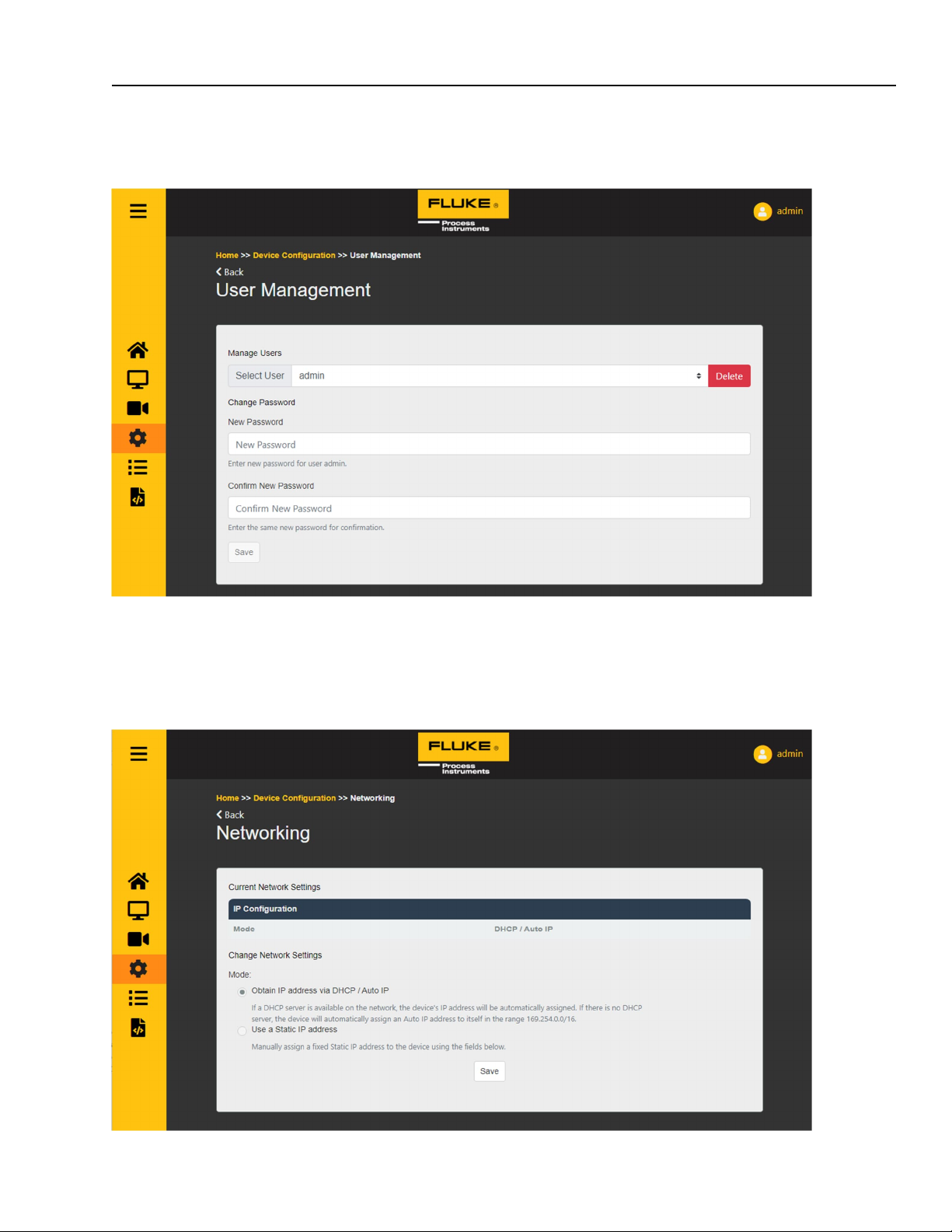
Delete: deletes the selected use r account
Use “new password” and “confirm new password” to set the password of the selected user
5.4.2 Networking
25
Page 26
SV600Series
Users Manual, Rev. 2.3, Jun 2022
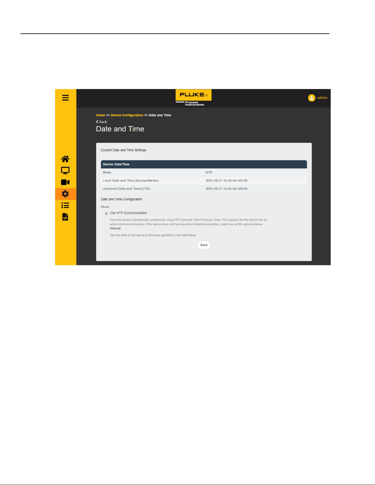
Swap network settings by choosing between automatic or static IP
Only use the static IP configuration if you know what you are doing. Check “SETTING UP A SV600” for
further information
5.4.3 Date and Time
NTP is the default synchronization method. It uses the router/modem in the network or the Google NTP
server.
You can also set the time manually. Use the “sync with computer time” flag to automatically fill in your
device’s time or fill in a time manually.
26
Page 27
5
5.4.4 Device Information
SV600 Dashboard
Device Configuration Pages
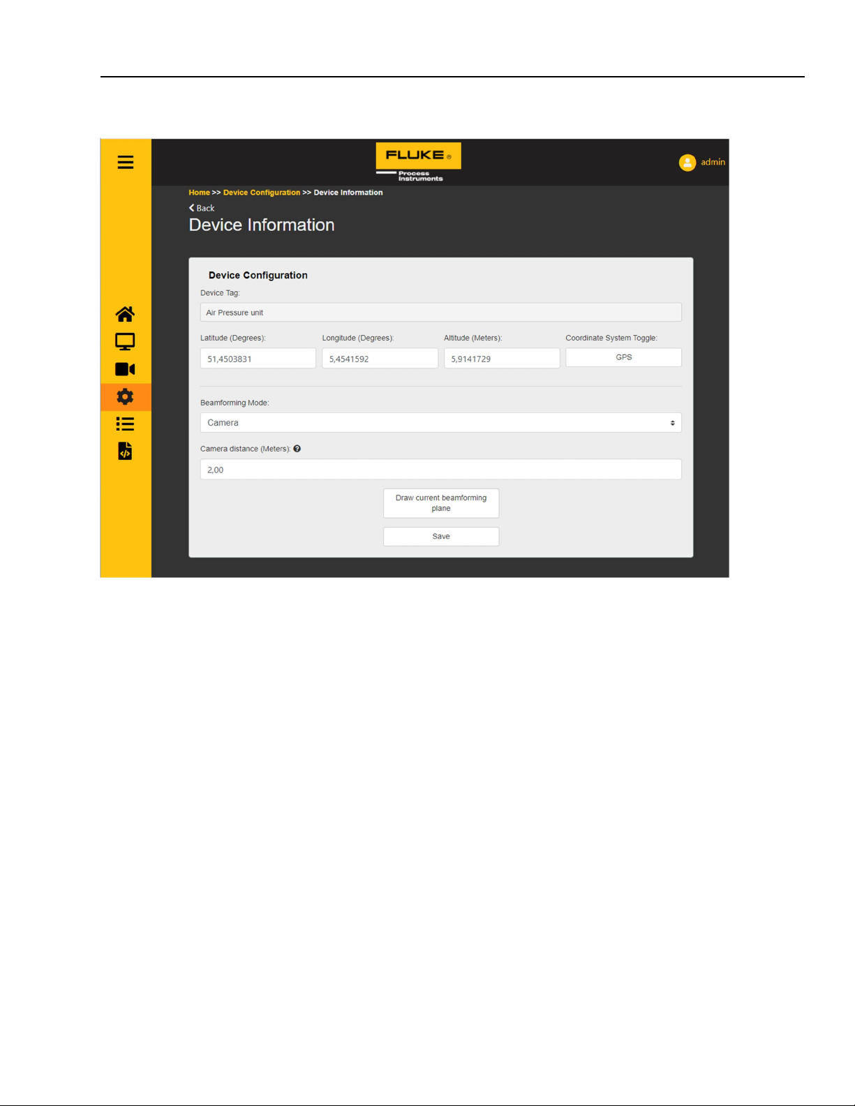
Device Tag: A user settable name for this device
Latitude/Longitude/Altitude or X/Y/Z: Set the (GPS) location for this device.
Beamforming mode: By default Camera mode
Camera Distance: Configure the distance between the device and the target (e.g. Leak or machine)
27
Page 28
SV600Series
Users Manual, Rev. 2.3, Jun 2022
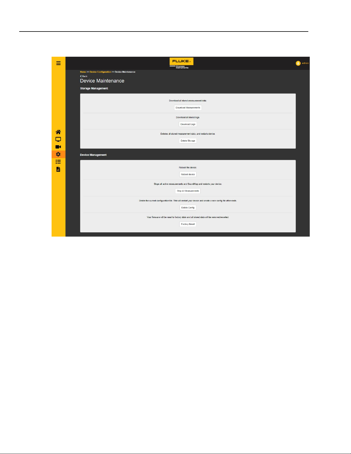
5.4.5 Device Maintenance
“Download Measurements”: Download the data of all measurements that are stored on the device .
“Download Logs”: Download the data of all logs that are stored on the device.
“Delete Storage”: Deletes all stored measurement data, and restarts device
“Reboot Device”: Give the device a reboot.
“Stop All Measurements”: Stops all active Measurements and SoundMaps and restarts device.
“Delete Config”: Deletes the current configuration file. This will restart your device and create a new config
file afterwards.
“Factory Reset”: Your firmware wil l be reset to factory state and all stored data will be removed/reverted.
28
Page 29
SV600 Dashboard
5
Management Pages
5.5 Management Pages
In the management pages, a user can see which entities are running and active on the device. There are tabs for
different groups of entities. Certain entities are made by the dashboard. They have a visible tag and a flag indica ting
this.
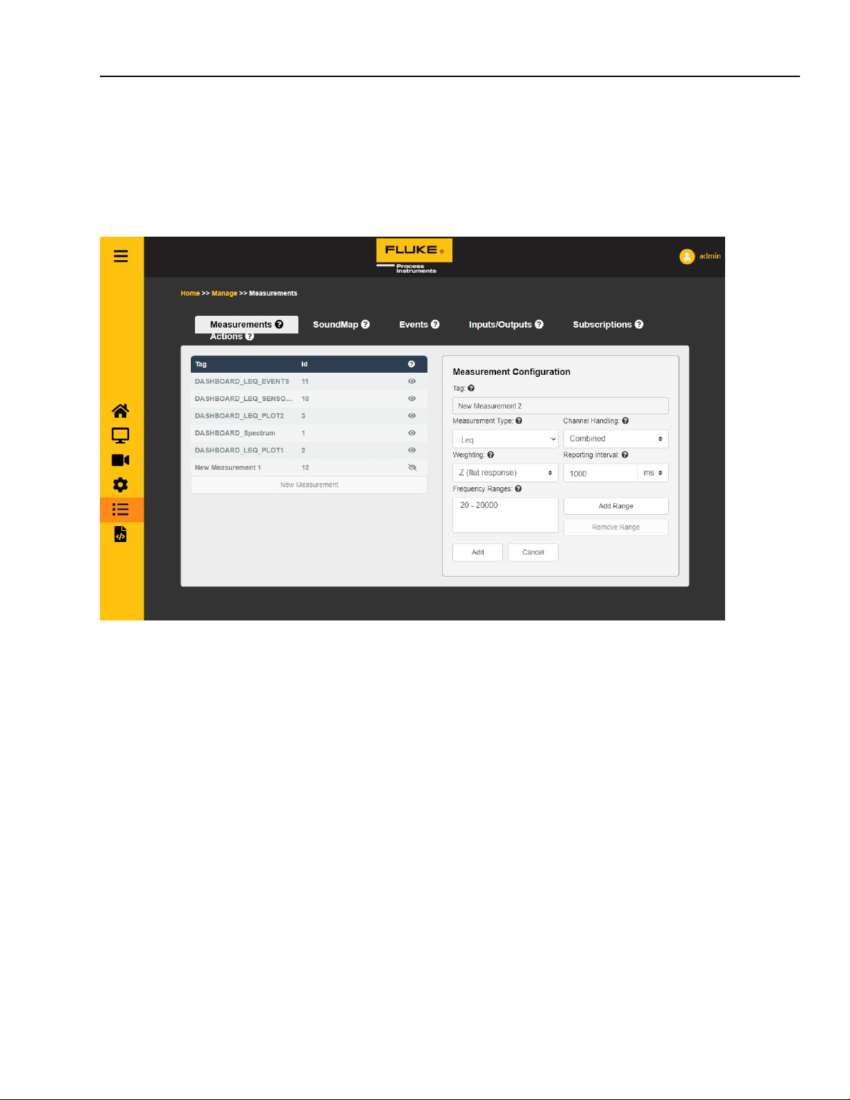
5.5.1 Measurements
To the left is a list of all active measurements on the device.
o “Tag” is a human readable name of a measurement
o “Id” is the unique number assigned to each measurement. Ids are always unique; tags don’t
have to be.
o An open eye in the last column shows that a measurement is created by the front-end. A closed
eye means a measurement is created by a user.
o “New Measurement” can be clicked to start adding a new measurement. The settings to the right
should then be filled in.
To the right the settings of a selected or new measurement can be seen
o “Tag” is the na me of the measurement
o “Measurem ent Type” is the type of measurement. Examples are Leq, Spectrum, or Classification
When selecting Classification, anomaly detection can be selected. When this
measurement will be saved, the Anomaly Detetcor will train to the surrounding sound
for 60 seconds. After this training period, the Anomaly Detector will trigger on any sound
that is different from what it trained to .
A PD (Partial Discharge) classification measurement will trigger when PD sounds are
recognised by the device.
o “Channel Handling” tells is the measurement will combine the 64 channels or gives back
separate results.
o “Weighting” can be used to apply a certain pre-defined acoustic weighting to results
o “Reporting Interval” is how often the measurement will produce a result. Audio is averaged over
this duration.
o “frequency ranges” can be selected and edited, added or removed.
29
Page 30
SV600Series
Users Manual, Rev. 2.3, Jun 2022
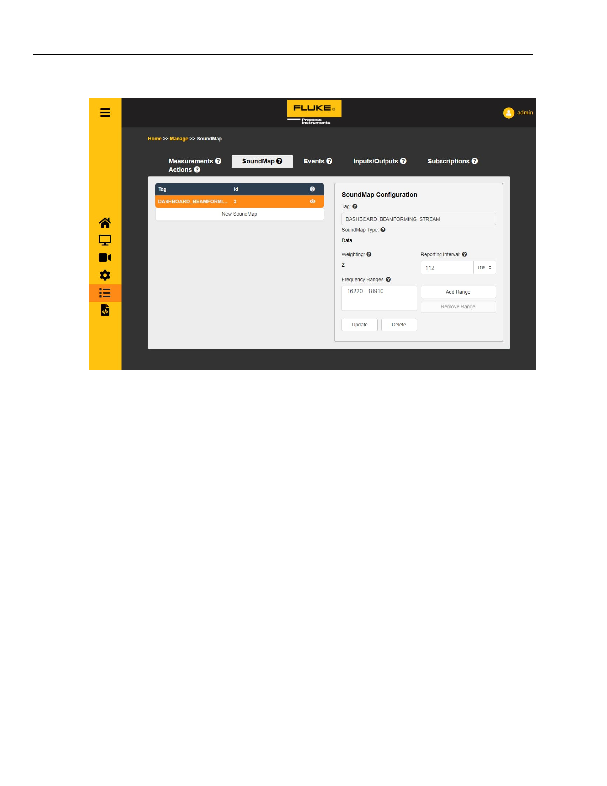
5.5.2 SoundMap
To the left is a list of all active SoundMaps on the device.
o “Tag” is a human readable name of a SoundMap
o “Id” is the unique number assigned to each SoundMap. Ids are always unique; tags don’t have
to be.
o An open eye in the last column shows that a SoundMap is created by the front-end. A closed
eye means a SoundMap is created by a user.
o “New SoundMap” can be clicked to start adding a new SoundMap. The settings to the right
should then be filled in.
To the right the settings of a selected or new SoundMap can be seen
o “Tag” is the na me of the SoundMap
o “SoundMap Type” is the type of SoundMap. Examples are “Data” or “Image”.
o “Weighting” can be used to apply a certain pre-defined acoustic weighting to results
o “Reporting Interval” is how often the SoundMap will produce a result. Audio is averaged over
this duration.
o “frequency ranges” can be selected and edited, added or removed. Note that there is a maximum
total range the device can analyse. In this release this is 8000Hz.
30
Page 31
5
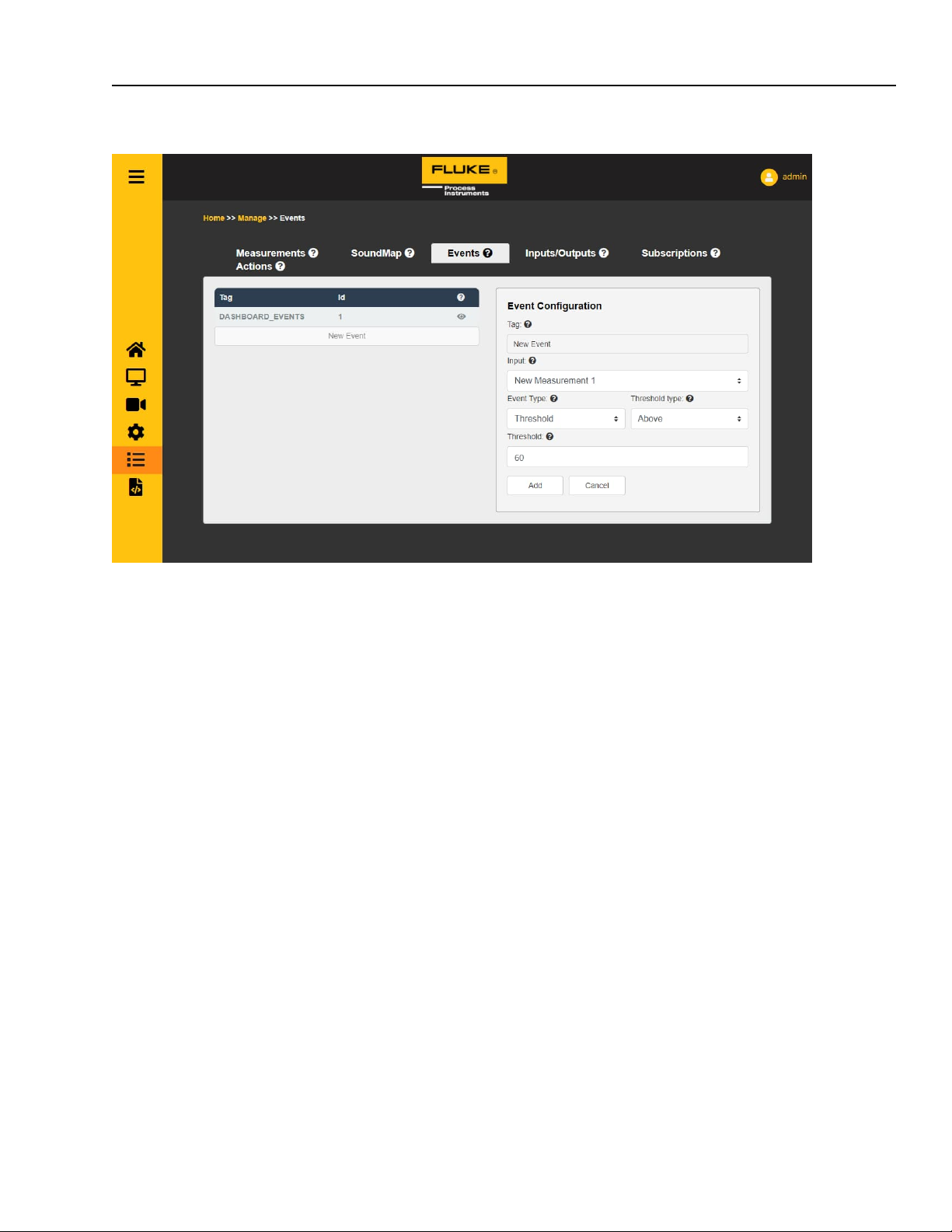
5.5.3 Events
SV600 Dashboard
Management Pages
To the left is a list of all active events on the device.
o “Tag” is a human readable name of an event
o “Id” is the unique number assigned to each event. Ids are always unique; tags don’t have to be.
o An open eye in the last column shows that an event is created by the front-end. A closed eye
means an event is created by a user.
o “New Event” can be clicked to start adding a new event. The settings to the right should then be
filled in.
To the right the settings of a selected or new event can be seen
o “Tag” is the name of the event
o “Input” is the entity this event is added to. This can be a measurement or a SoundMap
If an Anomaly Detector is wanted as an input measurement, the even t type should first
be set to Classification.
o “Event Type” is the type of event. Examples are Threshold Range or Classification. If
classification is selected, the event will trigger when an anomaly has been detected.
o Depending on the “Event Type” there are other settings available which tell the syste m when to
trigger this event. For example “Threshold Above 60dB”
31
Page 32
SV600Series
Users Manual, Rev. 2.3, Jun 2022
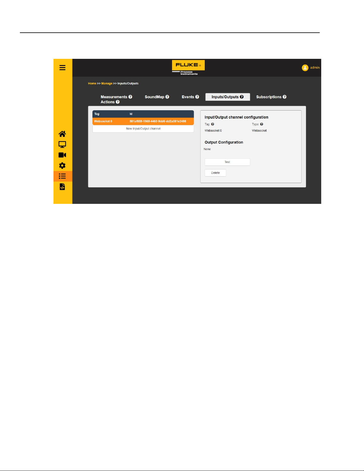
5.5.4 Inputs/Outputs
To the left is a list of all active Input/Output channels on the device
o “Tag” is a human readable name of a Input/Output channel
o “Id” is the unique GUID assigned to each Input/Output channel. Ids are always unique; tags don’t
have to be.
o An open eye in the last column shows that an Input/Output channel is created by the front-end.
A closed eye means an Input/Output channel is created by a user.
o “New Input/Output Channel” can be clicked to start adding an Input/Output channel. The settings
to the right should then be filled in.
To the right the settings of a selected or new Input/Output channel can be seen
o “Tag” is the na me of the Input/Output channel
o “Type” is the type of Input/Output channel. Current types are Websocket and “ModbusTCP”
When “ModbusTCP” is selected these options are available
“IP Address” the IP address of the Modbus device
“Port” the port number of the Modbus device
“Register Type” the type of register the SV600 should control
“Address” is the address number of the register
“Value” is the value the SV600 should if we trigger this Modbus connection
See “SETTING UP A SOUNDMAP EVENT TRIGGER ON A WAGO UNIT” for
more information
o “Test” can be used to test if the Input/Outpu t channel is reachable. If clicke d and successful the
button turns green, red if it could not reach it.
32
Page 33
5
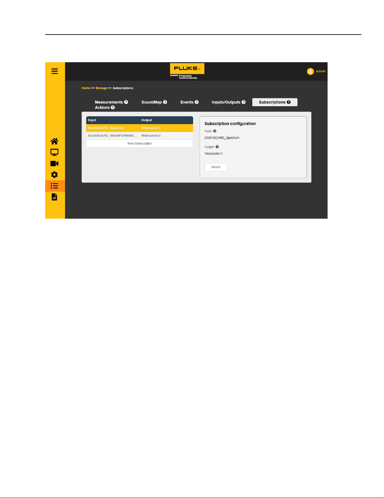
5.5.5 Subscriptions
SV600 Dashboard
Management Pages
To the left is a list of all active subscriptions on the device.
o “Input” is the input of a subscription
o “Output” is the name of the Output channel this subscription is sending its results to
o “New Subscription” can be clicked to start adding a new subscription. The settings to the right
should then be filled in.
To the right the settings of a selected or new subscription can be seen
o “Input” is the entity which provides data for this subscription.
o “Output Channel” is the callback channel this subscription sends the data, provided by the input,
to.
33
Page 34
SV600Series
Users Manual, Rev. 2.3, Jun 2022
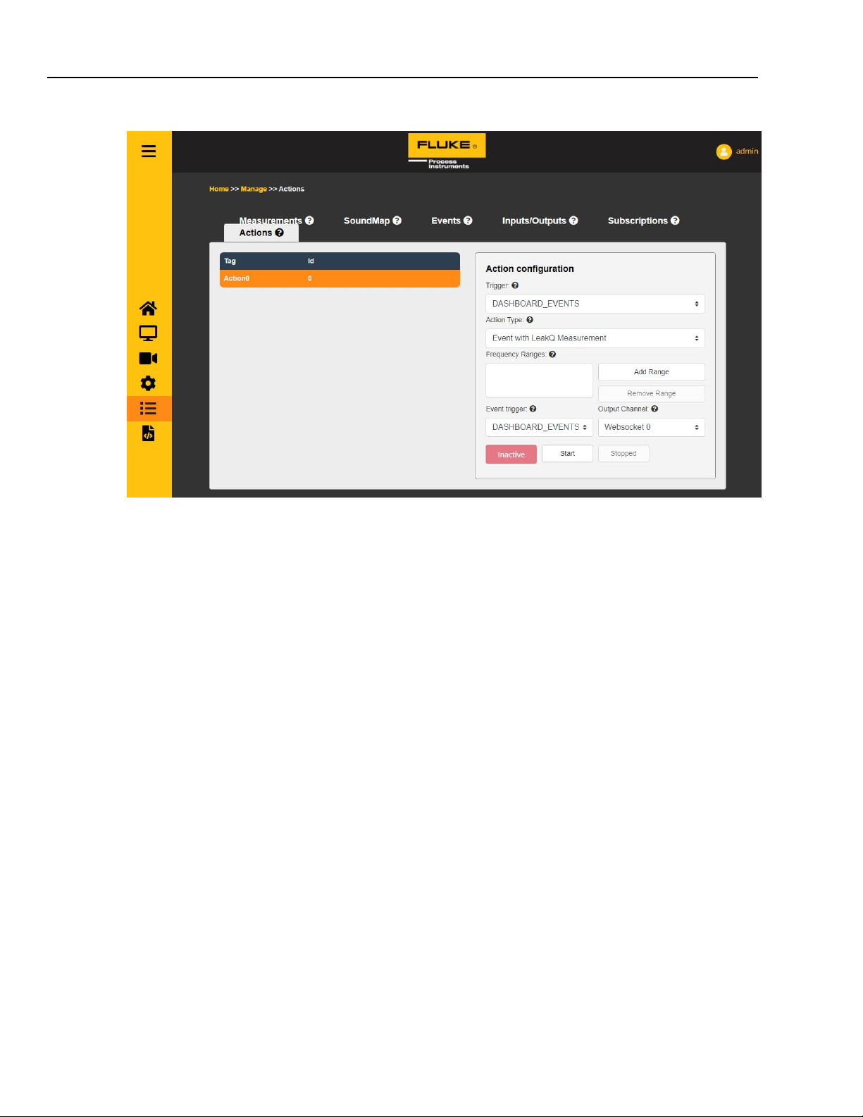
5.5.6 Actions
To the left is a list of all active actions on the device. The system currently only supports one action,
which can be activated by the user.
o “Tag” is a human readable name of an action.
o “Id” is a unique id the system assigned to this action.
To the right are the settings of the selected action.
o “Trigger” which entity triggers (enables) this action.
o “Action type” which action to perform when a trigger is received.
o “Frequency ranges” can be selected and edited, added or removed. Note that there is a
maximum total range the device can analyze. In this release this is 8000Hz.
o EventWithAS2 only settings.
“Event trigger” while active, which input will trigger this action’s action
“Output Channel” to which output channel any received inputs are forwarded to.
5.6 API Documentation
This page contains documentation on the SV600 device. The API is based on a HTTP REST API. All calls are
communicated via HTTP or WebSocket. The API protocol is split in three levels. The device hosts the following
documents:
1. Sound Source Detection API
2. Authentication API
3. Device manager
4. Quick Start Guide PDF
5. User manual PDF
34
Page 35
SV600 Dashboard
5
Setting up a SoundMap Event Trigger on a Wago Unit
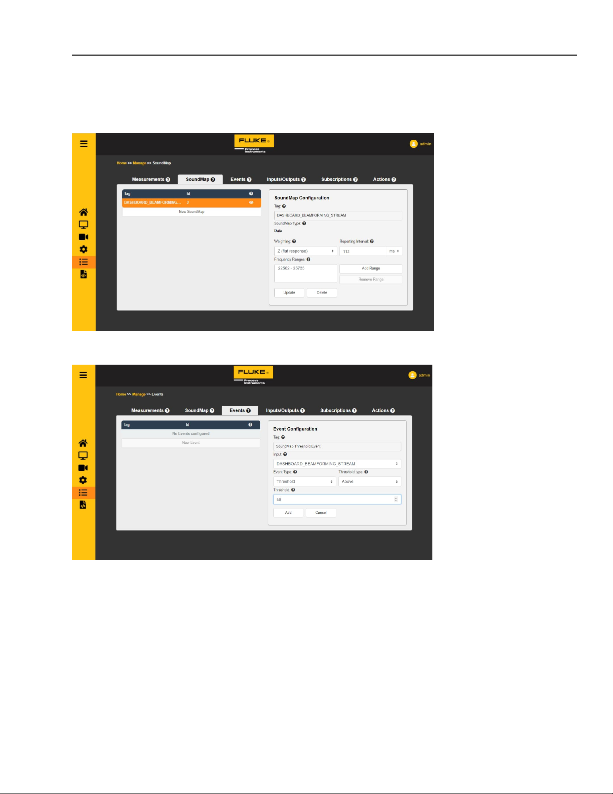
5.7 Setting up a SoundMap Event Trigger on a Wago Unit
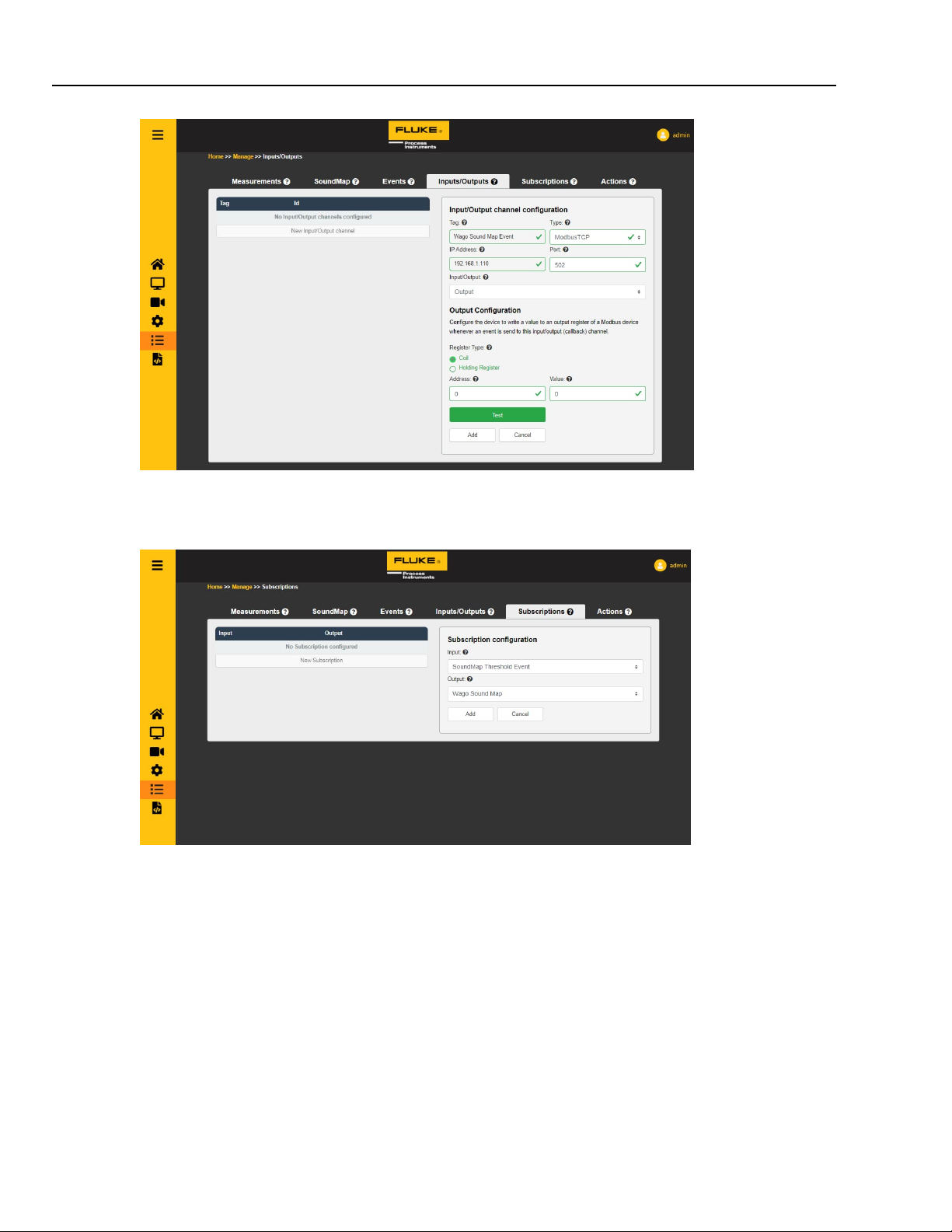
First go to the management page and check if a valid SoundMap is running. If no SoundMap is running either
create a new one or go to the streaming page to generate one.
Next go to the event tab and create a new event with the SoundMap measurement as an input, and a recognizable
tag.
Then go to the inputs/outputs tab, and create a new WAGO Output channel.
Fill in the required fields and test your callback by pressing the test button to validate it is set up correctly.
If your settings are correct this should send the signal you have set up to the WAGO unit.
35
Page 36
SV600Series
Users Manual, Rev. 2.3, Jun 2022
For the final step go to the subscription tab to create a new subscription.
Choose your created event as an input and your WAGO unit as an output channel.
Once this is submitted the set-up signal will be sent to the WAGO unit every time the linked event is triggered.
36
Page 37

Troubleshooting
6
How to check device health / when to request a new device, since too broken?
6 Troubleshooting
6.1 How to check device health / when to request a new device, since too broken?
Microphone health can be monitored on the sensor SPL page of the device. A microphone is faulty, when it is
stuck on a single value or when its value is very dissimilar to the values of the other microphones. A good rule of
thumb is: replace the device when more than 30 microphones display these kinds of symptoms.
When using our plain API: use the output of a measurement with as type Leq and as channels Separate. You
would have to analyze those results to figure out if one or more microphones show signs of failure.
6.2 Stream page does not show SoundMap overlay or spectrum
It is possible that there is a large difference between the time the SV600 thinks it is and between what your PC
thinks it is. To resolve this, you can set the device time to match your PC’s time. Check section 5.4.3 Date and
Time, page 26 on how to do this.
6.3 I set a certain reporting interval, but data is returned at a slower rate
It is possible that a selection of measurements and SoundMap is selected which the device is not able to run live.
Usually this happens if 2 “Data” SoundMaps are active. Remove one of them and give the device a restart. If it still
persist, also remove some measurements and reboot the device.
6.4 How do I restart my device without removing power
Via the API, you can do a reboot call, check the device manager API documentation for that. For front-end users,
the easiest way is to go to Device Information and press save without changing anything. This will reboot the
device.
37
 Loading...