

Page 1

SimpliFiber® Pro
September 2008, Rev. 1 10/10
©2008, 2010 Fluke Corporation. All rights reserved.
All product names are trademarks of their respective companies.
Optical Power Meter and Fiber Test Kits
Users Manual
Page 2

LIMITED WARRANTY AND LIMITATION OF LIABILITY
Each Fluke Networks product is warranted to be free from defects in material and workmanship under normal use and service. The
warranty period for the mainframe is one year and begins on the date of purchase. Parts, accessories, product repairs and services are
warranted for 90 days, unless otherwise stated. Ni-Cad, Ni-MH and Li-Ion batteries, cables or other peripherals are all considered parts
or accessories. The warranty extends only to the original buyer or end user customer of a Fluke Networks authorized reseller, and does
not apply to any product which, in Fluke Networks’ opinion, has been misused, abused, altered, neglected, contaminated, or damaged
by accident or abnormal conditions of operation or handling. Fluke Networks warrants that software will operate substantially in
accordance with its functional specifications for 90 days and that it has been properly recorded on non-defective media. Fluke Networks
does not warrant that software will be error free or operate without interruption.
Fluke Networks authorized resellers shall extend this warranty on new and unused products to end-user customers only but have no
authority to extend a greater or different warranty on behalf of Fluke Networks. Warranty support is available only if product is
purchased through a Fluke Networks authorized sales outlet or Buyer has paid the applicable international price. Fluke Networks
reserves the right to invoice Buyer for importation costs of repair/replacement parts when product purchased in one country is
submitted for repair in another country.
Fluke Networks warranty obligation is limited, at Fluke Networks option, to refund of the purchase price, free of charge repair, or
replacement of a defective product which is returned to a Fluke Networks authorized service center within the warranty period.
To obtain warranty service, contact your nearest Fluke Networks authorized service center to obtain return authorization information,
then send the product to that service center, with a description of the difficulty, postage and insurance prepaid (FOB destination). Fluke
Networks assumes no risk for damage in transit. Following warranty repair, the product will be returned to Buyer, transportation
prepaid (FOB destination). If Fluke Networks determines that failure was caused by neglect, misuse, contamination, alteration, accident
or abnormal condition of operation or handling, or normal wear and tear of mechanical components, Fluke Networks will provide an
estimate of repair costs and obtain authorization before commencing the work. Following repair, the product will be returned to the
Buyer transportation prepaid and the Buyer will be billed for the repair and return transportation charges (FOB Shipping point).
THIS WARRANTY IS BUYER’S SOLE AND EXCLUSIVE REMEDY AND IS IN LIEU OF ALL OTHER WARRANTIES, EXPRESS OR IMPLIED,
INCLUDING BUT NOT LIMITED TO ANY IMPLIED WARRANTY OR MERCHANTABILITY OR FITNESS FOR A PARTICULAR PURPOSE. FLUKE
NETWORKS SHALL NOT BE LIABLE FOR ANY SPECIAL, INDIRECT, INCIDENTAL OR CONSEQUENTIAL DAMAGES OR LOSSES, INCLUDING
LOSS OF DATA, ARISING FROM ANY CAUSE OR THEORY.
Since some countries or states do not allow limitation of the term of an implied warranty, or exclusion or limitation of incidental or
consequential damages, the limitations and exclusions of this warranty may not apply to every buyer. If any provision of this Warranty
is held invalid or unenforceable by a court or other decision-maker of competent jurisdiction, such holding will not affect the validity or
enforceability of any other provision.
4/04
Fluke Networks
PO Box 777
Everett, WA 98206-0777
USA
Page 3

Contents
Title Page
Introduction .......................................................................................................................................................................... 1
Registration ........................................................................................................................................................................... 1
The Fluke Networks Knowledge Base ................................................................................................................................. 2
Contacting Fluke Networks .................................................................................................................................................. 2
Safety Information ................................................................................................................................................................ 2
Unpacking ............................................................................................................................................................................. 4
FTK1000 .......................................................................................................................................................................... 4
FTK1300 .......................................................................................................................................................................... 4
FTK1350 .......................................................................................................................................................................... 4
FTK1450 .......................................................................................................................................................................... 5
FTK2000 .......................................................................................................................................................................... 5
FTK2100 .......................................................................................................................................................................... 6
SFPOWERMETER ............................................................................................................................................................ 6
SFMULTIMODESOURCE ................................................................................................................................................. 6
SFSINGLEMODESOURCE ................................................................................................................................................ 6
SFSINGLEMODE2 ............................................................................................................................................................ 6
Battery Installation, Life, and Status .................................................................................................................................... 7
Meter and Source Features .................................................................................................................................................. 8
Display Features .................................................................................................................................................................... 10
i
Page 4

SimpliFiber Pro Meter and Test Kits
Users Manual
Setting User Preferences .......................................................................................................................................................12
Continuous Wave/2 kHz Modes ............................................................................................................................................ 14
Auto Wavelength Mode ....................................................................................................................................................... 14
Cleaning Connectors and Adapters ......................................................................................................................................15
Cleaning Bulkhead Connectors (sources and patch panels) ........................................................................................15
Cleaning the Meter’s Connector ...................................................................................................................................15
Cleaning Fiber Adapters ................................................................................................................................................15
Cleaning Connector Ends ............................................................................................................................................... 16
Changing the Connector Adapter ........................................................................................................................................ 16
Detecting Active Fibers ......................................................................................................................................................... 18
Locating Fibers ....................................................................................................................................................................... 20
Measuring Optical Power .....................................................................................................................................................22
Using the Min/Max Function ......................................................................................................................................... 24
Measuring Loss ...................................................................................................................................................................... 25
About 1 Jumper Connections ........................................................................................................................................ 25
Testing the Test Reference Cords .................................................................................................................................. 25
About Referencing ......................................................................................................................................................... 25
Setting the Reference .................................................................................................................................................... 25
Measuring Loss ...............................................................................................................................................................28
If Loss is Negative ...........................................................................................................................................................31
Memory Functions .................................................................................................................................................................31
Viewing and Deleting Records ......................................................................................................................................31
Uploading Records to a PC ............................................................................................................................................33
Maintenance .......................................................................................................................................................................... 34
Cleaning ..........................................................................................................................................................................34
Checking the Meter’s Software Version and Calibration Date ...................................................................................34
Options and Accessories ........................................................................................................................................................ 34
Specifications .........................................................................................................................................................................35
ii
Page 5

Contents
Environmental Specifications ........................................................................................................................................ 35
Meter Specifications ...................................................................................................................................................... 35
Multimode Source ......................................................................................................................................................... 37
1310 nm/1550 nm Singlemode Source ......................................................................................................................... 39
1490 nm/1625 nm Singlemode Source ......................................................................................................................... 41
FindFiber Source Specifications ..................................................................................................................................... 43
Certifications, Compliance, and Regulatory Information ........................................................................................... 44
Appendix A: How to Test Your Test Reference Cords ........................................................................................................ 45
Appendix B: Using Mandrels ................................................................................................................................................ 51
Appendix C: Fiber Test Method Names ............................................................................................................................... 55
Appendix D: Loss Test Methods ........................................................................................................................................... 57
Index ...................................................................................................................................................................................... 67
iii
Page 6

SimpliFiber Pro Meter and Test Kits
Users Manual
iv
Page 7

List of Figures
Figure Page
1. Installing the Batteries.......................................................................................................................................... 7
2. Meter and Source Features ..................................................................................................................................8
3. Display Features ....................................................................................................................................................10
4. Installing the Connector Adapter ........................................................................................................................ 17
5. Detecting Active Fibers.........................................................................................................................................19
6. Using FindFiber Mode to Locate Fibers ...............................................................................................................21
7. Power Measurement Connections.......................................................................................................................22
8. Power Measurement Display................................................................................................................................23
9. Power Measurement Display with Min/Max Function Enabled.........................................................................24
10. Reference Connections (1 Jumper method)........................................................................................................27
11. Loss Measurement Connections (1 Jumper method).......................................................................................... 29
12. Loss Measurement Display ...................................................................................................................................30
13. View Record Display .............................................................................................................................................32
14. Connecting to a PC ...............................................................................................................................................33
A-1. Equipment for Testing the Test Reference Cords ...............................................................................................46
A-2. Examples of Fiber Endfaces..................................................................................................................................47
A-3. Connections for Testing a Test Reference Cord.................................................................................................. 49
B-1. Wrapping a Test Reference Cord Around a Mandrel......................................................................................... 52
B-2. Mandrel Placement...............................................................................................................................................53
v
Page 8

SimpliFiber Pro Meter and Test Kits
Users Manual
Figure Page
D-1. Reference and Test Connections for the 1 Jumper Method...............................................................................59
D-2. Reference and Test Connections for the 2 Jumper Method...............................................................................61
D-3. Reference and Test Connections for the 3 Jumper Method...............................................................................63
D-4. Reference and Test Connections for the Modified 1 Jumper Method ..............................................................65
vi
Page 9

SimpliFiber® Pro Fiber Test Kits
Introduction
The SimpliFiber® Pro Fiber Test kits provide an optical power
meter, optical power source, and fiber locator that let you do
the following:
•
Measure optical power or power loss at multiple
wavelengths in one test. The meter measures at 850 nm,
1300 nm, 1310 nm, 1490 nm, 1550 nm, and 1625 nm.
Source wavelengths depend on the model used.
•
Check fibers for optical activity with CheckActive
mode.
•
Identify links at patch panels with FindFiber™ mode.
•
Optional visual fault locator and fiber microscopes let
you locate cable faults and inspect fiber endfaces for
contamination or damage.
™
•
Save up to 1000 test records. You can use LinkWare™
software to upload the records to a PC and create
professional-quality test reports.
Registration
Registering your product with Fluke Networks gives you
access to valuable information on product updates,
troubleshooting tips, and other support services. To register,
fill out the online registration form on the Fluke Networks
website at www.flukenetworks.com/registration.
1
Page 10
SimpliFiber Pro Meter and Test Kits
Users Manual
The Fluke Networks Knowledge Base
The Fluke Networks Knowledge Base answers common
questions about Fluke Networks products and provides
articles on cable testing techniques and technology. To
access the Knowledge Base, log on to
www.flukenetworks.com, then click Support > Knowledge
Base.
Contacting Fluke Networks
•
Singapore: +65-6799-5566
•
Taiwan: (886) 2-227-83199
•
USA: 1-800-283-5853
Visit our website for a complete list of phone numbers.
Safety Information
Table 1 describes the international electrical symbols used on
the tester and in this manual.
www.flukenetworks.com
[email protected]
+1-425-446-4519
•
Australia: 61 (2) 8850-3333 or 61 (3) 9329 0244
•
Beijing: 86 (10) 6512-3435
•
Brazil: 11 3759 7600
•
Canada: 1-800-363-5853
•
Europe: +31-(0) 40 2675 600
•
Hong Kong: 852 2721-3228
•
Japan: 03-6714-3117
•
Korea: 82 2 539-6311
2
W
X
*
~
Table 1. International Electrical Symbols
Warning or Caution: risk of damage or
destruct
explanations in the manual.
Warning: Risk of electric shock.
Warning: Class 1 laser (singlemode and
FindFiber
hazardous radiation.
Do not put products containing circuit boards
into the
accordance with local regulations.
ion to equipment or software. See
sources). Risk of eye damage from
garbage. Dispose of circuits boards in
Page 11

Safety Information
WWarning: Class 1 Laser (singlemode and
FindFiber sources)
To avoid possible eye damage caused by hazardous
radiation:
•
Never look directly into optical connectors. Some
sources produce invisible radiation that can
permanently damage your eyes.
•
Never turn on the source unless a fiber is attached
to the port.
•
Do not use magnification to view the optical
outputs without proper filtering.
•
Use of controls, adjustments, or procedures not
stated herein might result in hazardous radiation
exposure.
*
WCaution
To avoid damaging fiber connectors, to avoid data
loss, and to ensure maximum accuracy of test
results:
•
Use proper cleaning procedures to clean all fiber
connectors before every use. Neglecting this step
or using improper procedures can cause unreliable
test results and may permanently damage the
connectors.
•
Cover all connectors with protective caps when not
in use.
•
Never connect the source to an active network.
Doing so can disrupt network operations.
3
Page 12

SimpliFiber Pro Meter and Test Kits
Users Manual
Unpacking
The SimpliFiber Pro Fiber Verification Kits come with the
accessories listed below. If something is damaged or
missing, contact the place of purchase immediately.
FTK1000
•
SimpliFiber Pro optical power meter
•
SimpliFiber Pro 850/1300 source
•
USB cable for PC communications
•
Carrying case
•
Getting Started Guide
•
SimpliFiber Pro Product Manuals CD
•
LinkWare Software CD
FTK1300
•
SimpliFiber Pro optical power meter
•
SimpliFiber Pro 850/1300 source
•
VisiFault™ Visual Fault Locator
•
FT120 FiberViewer™ Microscope
•
FindFiber™ Source
•
LC connector adapter
•
ST connector adapter
•
USB cable for PC communications
•
Carrying case
•
Getting Started Guide and Instruction Sheets
•
SimpliFiber Pro Product Manuals CD
•
LinkWare Software CD
FTK1350
•
SimpliFiber Pro optical power meter
•
SimpliFiber Pro 850/1300 source
•
VisiFault™ Visual Fault Locator
•
FT500 FiberInspector™ Mini Video Microscope
•
FindFiber™ Source
•
LC connector adapter
•
ST connector adapter
•
USB cable for PC communications
4
Page 13

•
Carrying case
•
Getting Started Guide and Instruction Sheets
•
SimpliFiber Pro Product Manuals CD
•
LinkWare Software CD
FTK1450
•
SimpliFiber Pro optical power meter
•
SimpliFiber Pro 850/1300 source
•
SimpliFiber Pro 1310/1550 source
•
VisiFault™ Visual Fault Locator
•
FT500 FiberInspector™ Mini Video Microscope
•
Two FindFiber™ Sources
•
LC connector adapter
•
ST connector adapter
•
USB cable for PC communications
•
NFC-Kit-Box Fiber Optic Cleaning Kit
•
Carrying case
•
Getting Started Guide and Instruction Sheets
•
SimpliFiber Pro Product Manuals CD
•
LinkWare Software CD
FTK2000
•
SimpliFiber Pro optical power meter
•
SimpliFiber Pro 1310/1550 source
•
USB cable for PC communications
•
Carrying case
•
Getting Started Guide
•
SimpliFiber Pro Product Manuals CD
•
LinkWare Software CD
Unpacking
5
Page 14

SimpliFiber Pro Meter and Test Kits
Users Manual
FTK2100
•
SimpliFiber Pro optical power meter
•
SimpliFiber Pro 1310/1550 source
•
SimpliFiber Pro 1490/1625 source
•
USB cable for PC communications
•
Carrying case
•
Getting Started Guide and Instruction Sheets
•
SimpliFiber Pro Product Manuals CD
•
LinkWare Software CD
SFPOWERMETER
•
SimpliFiber Pro optical power meter
•
USB cable for PC communications
•
Getting Started Guide
•
SimpliFiber Pro Product Manuals CD
SFMULTIMODESOURCE
•
SimpliFiber Pro 850/1300 source
•
Carrying pouch
•
Instruction Sheet
SFSINGLEMODESOURCE
•
SimpliFiber Pro 1310/1550 source
•
Carrying pouch
•
Instruction Sheet
SFSINGLEMODE2
•
SimpliFiber Pro 1490/1625 source
•
Carrying pouch
•
Instruction Sheet
6
Page 15
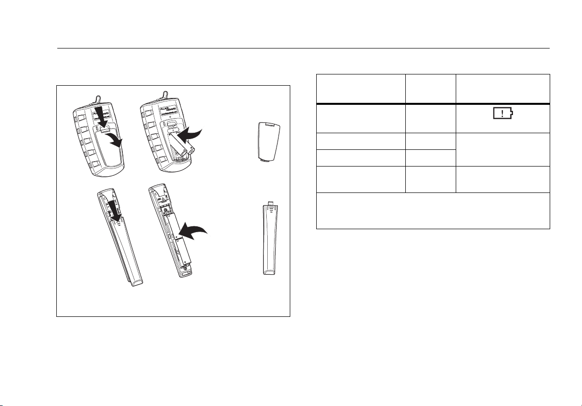
Battery Installation, Life, and Status
Battery Installation, Life, and Status
AA
IEC LR6
NEDA 15A
AA
IEC LR6
NEDA 15A
Note: Fluke Networks recommends alkaline batteries.
Figure 1. Installing the Batteries
ffl03.eps
Table 2. Battery Life and Low Battery Indicators
Battery
Device
Meter >50 hours
Life1 Low Battery Indicator
(blinks continuously)
Multimode source 40 hours
Singlemode sources 30 hours
LOW BATTERY LED
blinks conti
nuously
FindFiber source >80 hours LED blinks
continuously
1. Typical. See the specifications.
2. The LOW BATTERY LED blinks occasionally if auto power-off
is disabled. See page 12.
2
7
Page 16
SimpliFiber Pro Meter and Test Kits
Users Manual
Meter and Source Features
ffl04.eps
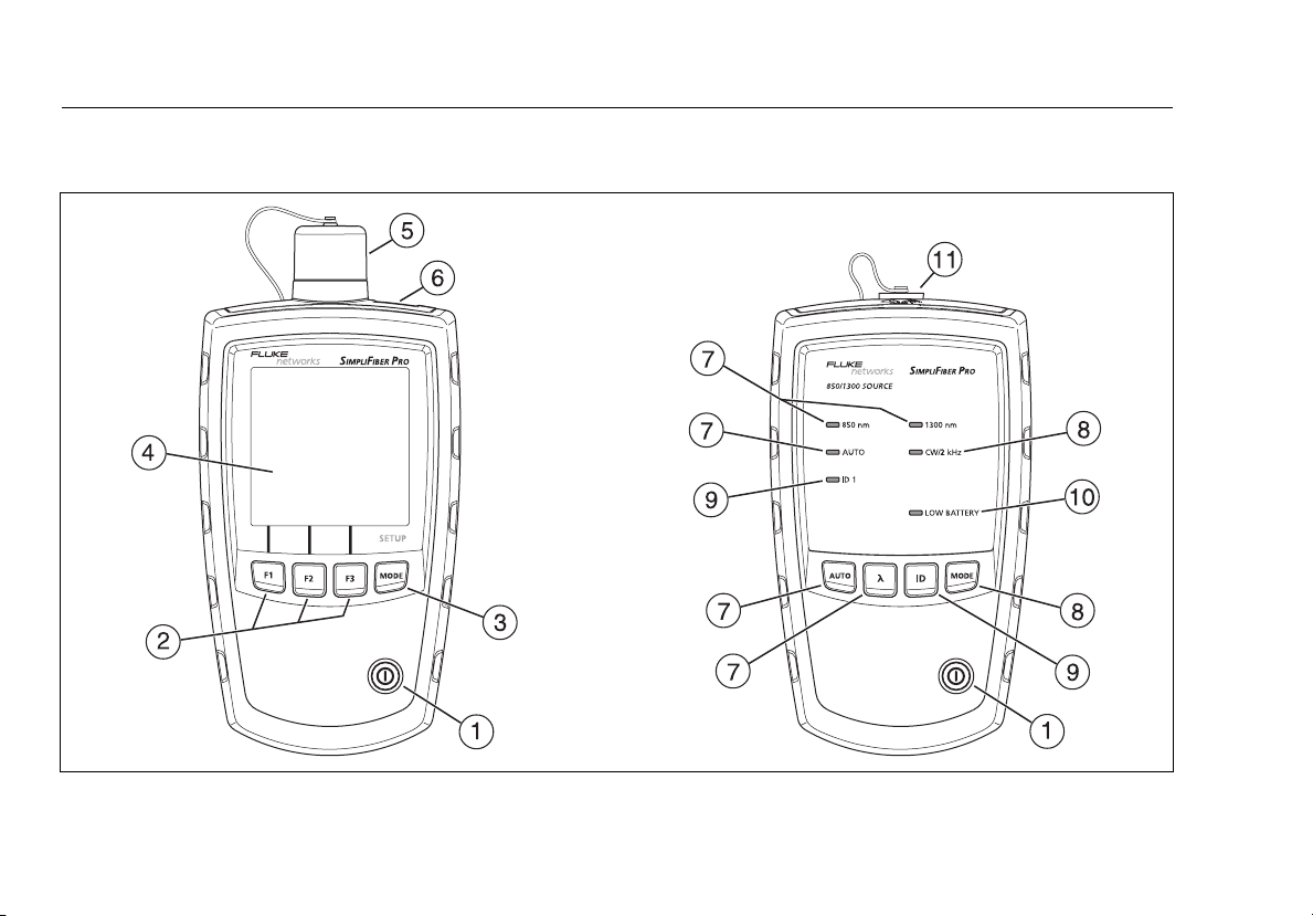
Figure 2. Meter and Source Features
8
Page 17

Meter and Source Features
A X: On/off key.
B R S T: Softkeys, which provide functions related to
the current display. The funtions are displayed above
the keys.
C M: Selects the meter’s measurement mode. To enter
setup mode, hold down
M for 4 seconds. See page 12.
D LCD display.
E Input port with interchangeable connector adapter. See
16.
page
F USB port for uploading test records to a PC. See page 33.
G A: Selects auto wavelength mode. The AUTO LED
lights. Press
wavelength LEDs indicate the wavelength. See page 14.
Z to change the wavelength. The
H M: Switches between continuous wave and 2 kHz
modulated output signals. The CW/2 kHz LED lights if
the output is continuous. It blinks if the output is
modulated. See page
Also enables or disables auto power-off. See page 12.
14.
I I: Selects FindFiber mode. The ID LED lights if the
source is in FindFiber mode. See page 20.
J The LOW BATTERY LED blinks continuously if the
battery is low. The LED blinks occasionally if auto poweroff is disabled. See page
12.
K Output port with SC adapter.
9
Page 18
SimpliFiber Pro Meter and Test Kits
C
L
M
O
D
RS
P
F
Users Manual
Display Features
E
H
G
F
E
D
B
C
I
J
A
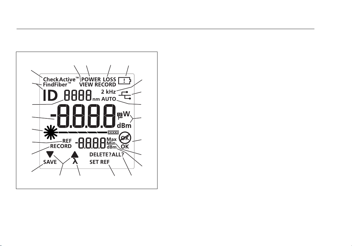
Figure 3. Display Features
K
Q
N
ffl01.eps
A DE: Indicates that pressing R or S scrolls through
choices in the current mode.
B SAVE: Indicates that pressing R saves the power or loss
measurement.
C RECORD: Label for the record number. VIEW RECORD:
Indicates the meter is displaying saved measurements.
See page 31.
D REF (reference): Label for the reference level in loss
mode. dBm: Measurement unit for the reference level.
See page 25.
E N WCheckActive
mode. CheckActive
fiber activity. See page 18.
F Numeric display with units for loss (dB) and power
measurements (mW, µW, dBm).
G Numeric display for the wavelength.
H FindFiber
source. ID is the label for the source’s identification
number, which appears on the numeric display (
page 20.
I POWER: The meter is measuring power. See page 22.
J LOSS: The meter is measuring power loss. See page 28.
™
: Indicates the meter is testing for a FindFiber
™
: Indicators for CheckActive
™
indicates the meter is testing for
F). See
10
Page 19

Display Features
K B: Low battery indicator. See page 7.
L 2 kHz: The meter detects a 2 kHz modulated optical
signal. See page
14.
M U: The meter is connected to a PC through the USB
port. See page 33.
N AUTO: The meter detects the auto wavelength
identifier in the optical signal. See page 14.
O OK O: The operation succeeded (OK) or failed O.
P Max Min: Indicators for maximum (Max) and minimum
(Min) power measurements. See page 24.
Q DELETE?: Indicates that pressing T deletes the current
record. DELETE ALL? indicates that pressing T deletes
all records. See page 31.
R SET REF: Indicates that pressing T saves the power
measurement as the reference value. See page 25.
S V: Indicates that pressing S changes the wavelength
being measured.
11
Page 20

SimpliFiber Pro Meter and Test Kits
Users Manual
Setting User Preferences
For the meter:
1
To enter setup mode, hold down M for 4 seconds.
2
To scroll through the setup items (Table 3), press M. To
change settings, press R D.
3
To exit setup mode, press M until the meter is in the
desired test mode.
For the source:
If auto power-off is enabled, the source turns off after 30
minutes if no keys are pressed.
To disable or enable auto power-off, hold down
seconds.
•
If auto power-off is enabled, all LEDs turn on for 3
seconds.
•
If auto power-off is disabled, all LEDs blink for 3 seconds
and the LOW BATTERY LED blinks occasionally.
M for 4
12
Page 21
Setting User Preferences
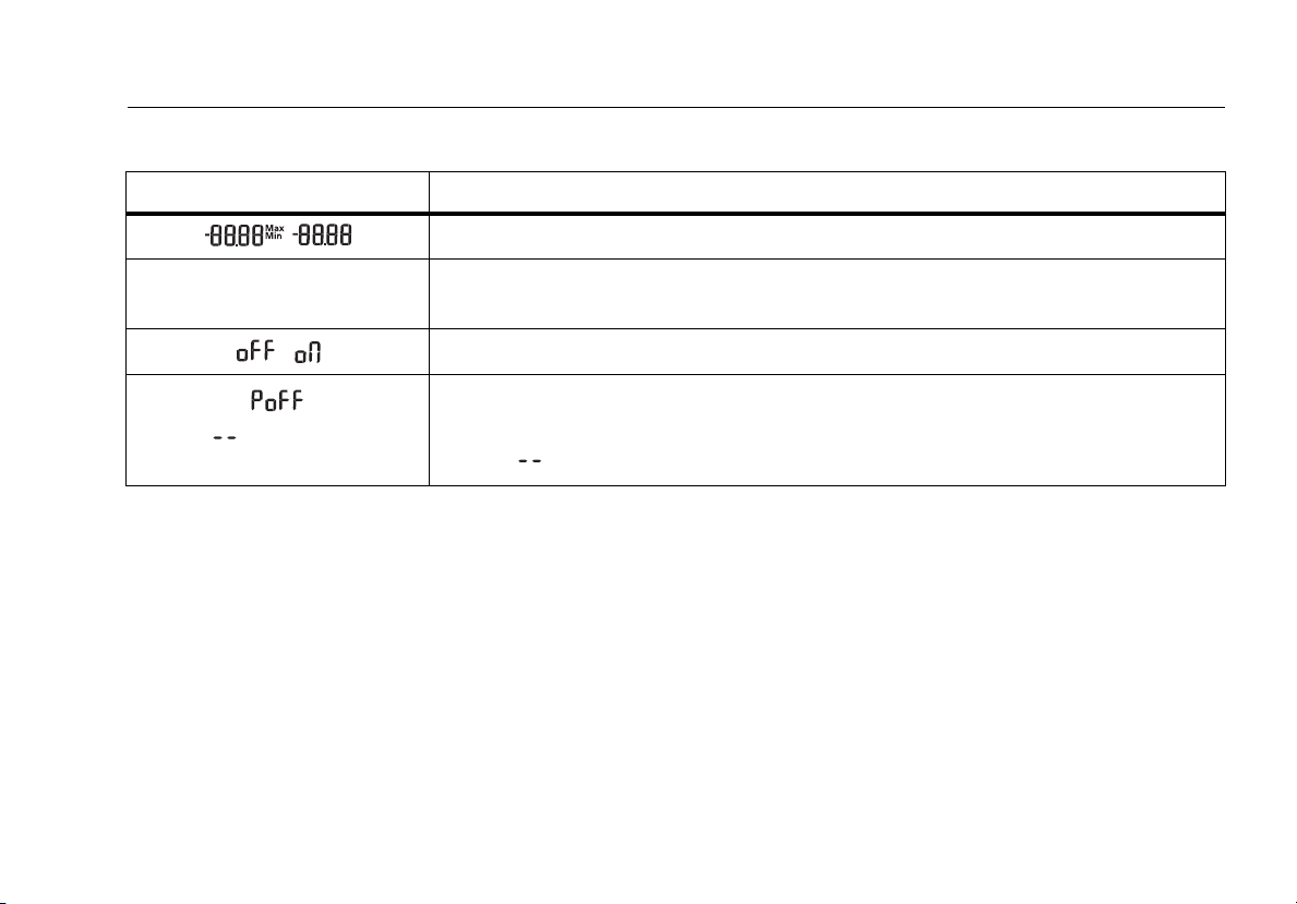
Table 3. Meter Setup Items
Meter Setup Item Choices
Enable or disable Min Max mode for power measurements.
mW µW dBm Select a unit for power measurements: milliwatts (mW), microwatts (µw), or decibels
relative to 1 mW (dBm).
Turn the backlight off or on.
Select a time period for the meter to turn off automatically if no keys are pressed. The
meter will not turn off if it is connected to a source that is in AUTO or ID mode.
10 20 30 60
Dashes ( ) indicate auto power-off is disabled.
13
Page 22

SimpliFiber Pro Meter and Test Kits
Users Manual
Continuous Wave/2 kHz Modes
Press M to switch the source between continuous wave and
2 kHz modulated output signals.
•
Use continuous wave mode (CW/2 kHz LED on steady) if
making loss or power measurements with a meter other
than a SimpliFiber Pro meter.
•
Use the 2 kHz modulated output mode (CW/2 kHz LED
blinking) if locating fibers with a meter other than a
SimpliFiber Pro meter.
Auto Wavelength Mode
In auto wavelength mode the source’s signal includes an
identifier that tells the meter which wavelength to measure.
You can set the source to one wavelength or to
automatically switch between wavelengths. When the
source is automatically switching, the meter can
automatically measure loss or power at each wavelength in
one test. If you save the measurements, the meter saves all
wavelengths measured in one record.
To set the source to auto wavelength mode:
1
If the AUTO LED is not on, press A.
2
Press Z to manually switch wavelengths (one
wavelength LED is on) or to set the meter to
automatically switch between wavelengths
(wavelength LEDs blink alternately).
If the meter detects the auto wavelength signal, AUTO
appears on the display, and the meter automatically
measures at the correct wavelength.
14
Page 23

Cleaning Connectors and Adapters
Cleaning Connectors and Adapters
Always clean and inspect fiber connectors before making
connections. Use fiber optic solvent and optical-grade wipes
or swabs to clean connectors as follows:
Cleaning Bulkhead Connectors (sources and patch panels)
1
Touch the tip of a fiber optic solvent pen or swab
soaked in solvent to a lint-free dry wipe or fiber
cleaning card.
2
Touch a new, dry swab to the solvent spot on the wipe
or card.
3
Push the swab into the connector, twist it around 3 to 5
times against the end-face, then remove and dispose of
the swab.
4
Dry the connector with a dry swab by twisting it
around in the connector 3 to 5 times.
5
Inspect connectors with a fiber microscope, such as the
Fluke Networks FiberInspector™ Video Microscope
before making connections.
Cleaning the Meter’s Connector
1
Remove the connector adapter to expose the
photodiode lens (see Figure 4).
2
Use the method described in steps 1 and 2 above to
dampen a swab with solvent.
3
Twist the damp swab around against the lens 3 to 5
times; then twist a dry swab around against the lens 3
to 5 times.
Cleaning Fiber Adapters
Periodically clean fiber adapters with a swab and fiber optic
solvent. Dry with a dry swab before use.
15
Page 24

SimpliFiber Pro Meter and Test Kits
Users Manual
Cleaning Connector Ends
1
Touch the tip of a fiber optic solvent pen or swab
soaked in solvent to a lint-free dry wipe or fiber
cleaning card.
2
Wipe the connector end-face across the solvent spot,
then back and forth once across the dry area of the
wipe or card.
Note
Some connector styles, such as VF-45, may require a
different cleaning method.
Always cover unused connectors with protective caps. Clean
caps periodically with a swab or wipe and fiber optic solvent.
Changing the Connector Adapter
You can change the meter’s connector adapter to connect to
SC, ST, and LC fiber connectors. Additional adapter styles
may be available. Check the Fluke Networks web site for
updates.
WCaution
•
Cover all connectors with dust caps when not in
use.
•
Store extra connector adapters in the canisters
provided.
•
Do not touch the photodiode lens (see Figure 4).
•
Do not overtighten the adapter or use tools to
tighten the adapter.
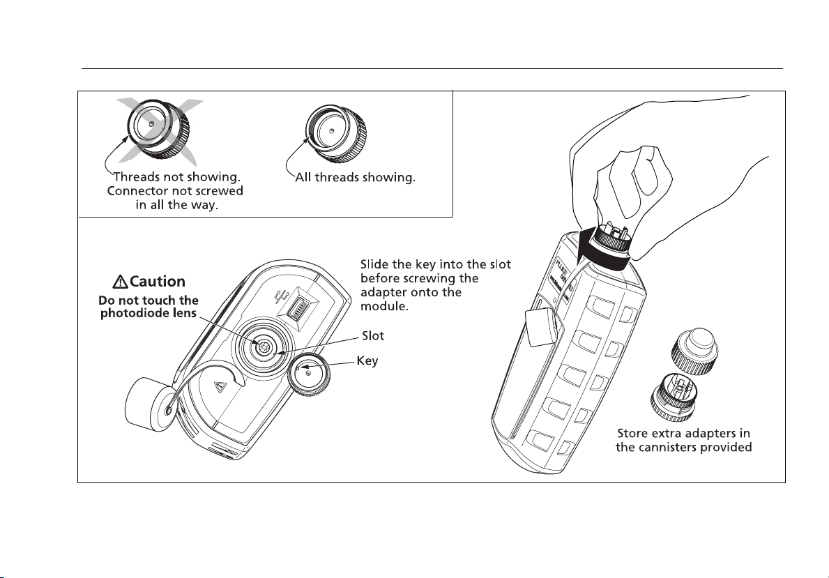
To install a connector adapter, refer to Figure 4 and do the
following:
1
Locate the slot in the meter’s connector and the key on
the adapter ring.
2
Holding the adapter so it does not turn in the nut,
align the adapter's key with the meter connector's slot
and slide the adapter onto the connector.
3
Screw the nut onto the meter connector.
16
Page 25
Changing the Connector Adapter
Figure 4. Installing the Connector Adapter
ffl05.eps
17
Page 26

SimpliFiber Pro Meter and Test Kits
Users Manual
Detecting Active Fibers
The meter’s CheckActive™ mode lets you quickly determine if
a fiber is connected to active equipment. This mode helps
you locate active links and avoid exposure to hazardous
radiation.
To use CheckActive mode:
1
Press M until CheckActive™ appears.
2
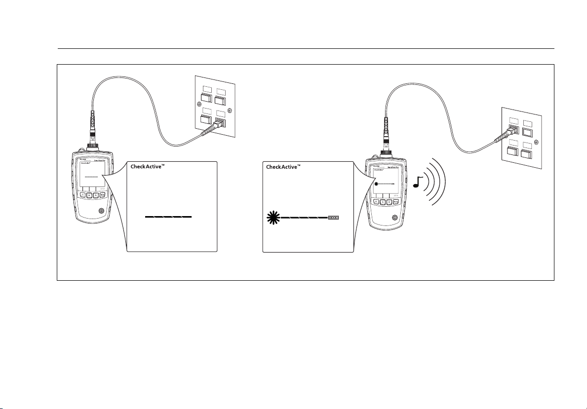
Connect the meter to a fiber. The meter indicates fiber
activity as shown in Figure 5.
Note
Ambient light can activate the CheckActive tone. To
avoid this, keep a patch cord connected to the
meter if the meter is in CheckActive mode.
18
Page 27
Inactive fiber Active fiber
Figure 5. Detecting Active Fibers
Detecting Active Fibers
ffl23.eps
19
Page 28

SimpliFiber Pro Meter and Test Kits
Users Manual
Locating Fibers
FindFiber mode helps you quickly identify link connections at
patch panels.
To use FindFiber mode:
1
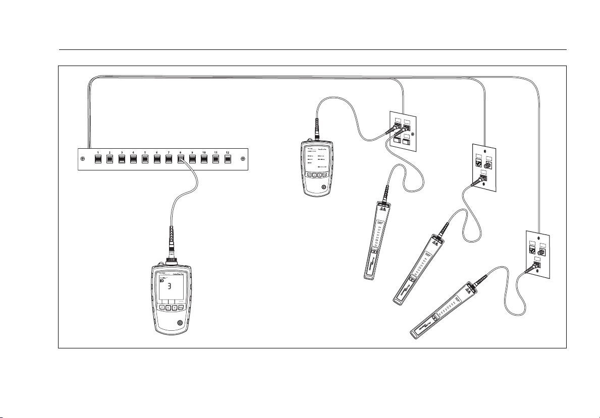
Connect the meter and a SimpliFiber source or one or
more FindFiber sources to the links as shown in Figure 6.
2
Turn on the meter and the source or FindFiber sources.
•
If you are using a SimpliFiber source, press I on the
source.
•
To change the number transmitted by a FindFiber
source, turn the source off, hold down the power key
for about 4 seconds; then release the key when the
desired LED turns on.
3
On the meter, press M until FindFiber™ appears.
4
The meter indicates connectivity as shown in Table 4:
Table 4. FindFiber Source Numbers
ID Number on
Source Connected
SimpliFiber Pro multimode source
SimpliFiber Pro singlemode source
1310/1550 nm
SimpliFiber Pro singlemode source
1490/1625 nm
FindFiber source Number indicated by
No continuity or incompatible
source connected
Note
In power or loss mode, ID blinks if
connected to a FindFiber source or a source in ID
mode.
the Me
1
2
3
the source’s LED
the meter is
ter
20
Page 29
Patch panel
Fiber links
SimpliFiber Pro
meter
Locating Fibers
ID #1
(multimode
source)
ID #3
ID #4
ID #5
Figure 6. Using FindFiber Mode to Locate Fibers
ffl19.eps
21
Page 30
SimpliFiber Pro Meter and Test Kits
Users Manual
Measuring Optical Power
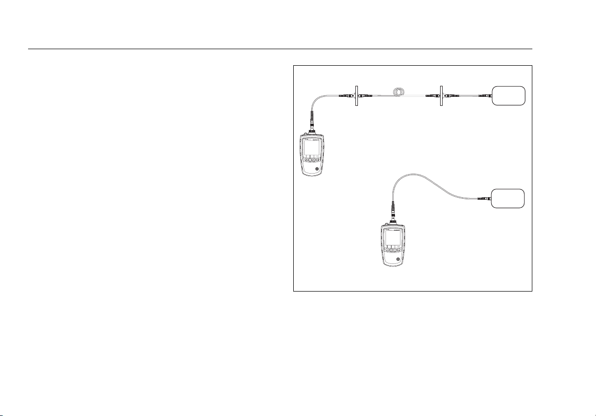
The power measurement shows the optical power level
produced by a source such as an optical network interface
card or optical test equipment.
To measure power:
1
Clean the connectors on the link or source to be tested.
Use fiber optic solvent and optical-grade wipes or
swabs to clean connectors as described on page 15.
2
On the meter, press M until POWER appears (Figure 8.)
3
Make the connections shown in Figure 7.
4
On the meter, press S V to select the wavelength
generated by the source.
5
To save the measurement, press R SAVE. The meter
briefly shows the record number and OK.
If the source was automatically switching wavelengths,
meter saves measurements for all wavelengths in
the
one record.
Fiber link
Optical
Measuring power at the
end of a link
Optical
Measuring power at a source
Figure 7. Power Measurement Connections
source
source
ffl09.eps
22
Page 31
A
C
D
B
E
Measuring Optical Power
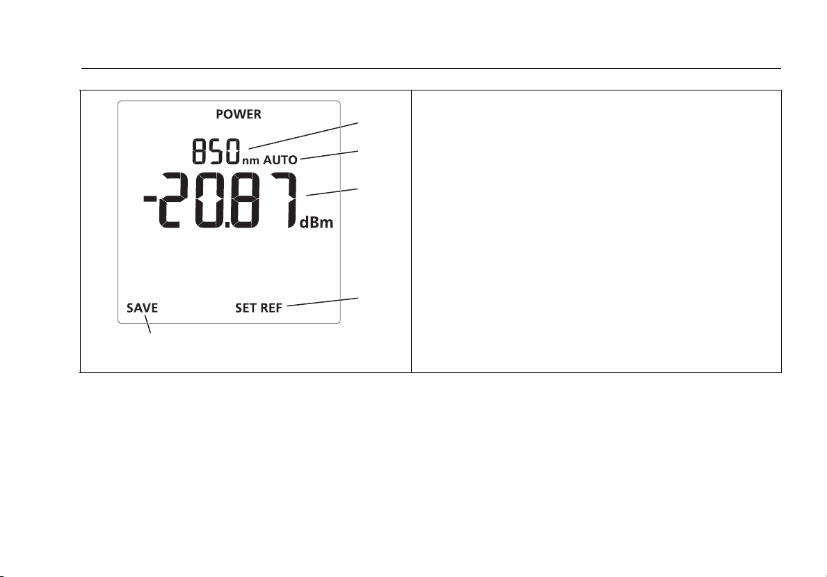
A The wavelength being measured.
B Indicates the meter is in auto wavelength mode.
C The power measurement. To change the measurement unit
see page 12.
D Pressing T SET REF saves the measured power level as the
reference and switches the meter to loss measurement
mode.
E Pressing R SAVE saves the measurement. If the source was
automatically switching wavelengths, the meter saves
measurements for all wavelengths in one record.
ffl20.eps
Figure 8. Power Measurement Display
23
Page 32
SimpliFiber Pro Meter and Test Kits
Users Manual
Using the Min/Max Function
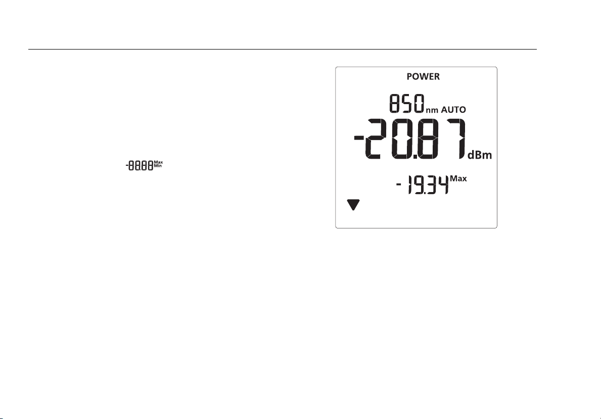
The Min/Max function shows the minimum and maximum
power levels measured for each wavelength.
To enable the Min/Max function:
1
On the meter, hold down M for 4 seconds to enter
setup mode.
2
Press R D so that appears.
3
Press M until POWER appears; then press M again to
see the Min/Max measurements (Figure 9).
The meter shows the minimum (Min)
and maximum
(Max) power levels measured since you entered the
power measurement mode at the selected wavelength.
4
To switch between minimum and maximum values,
R D.
press
Notes
The meter records new minimum and maximum
ues each time the wavelength changes.
val
You cannot save power measurements or set the
nce if Min or Max appear on the display.
refere
24
ffl14.eps
Figure 9. Power Measurement Display with Min/Max
Function Enabled
Page 33

Measuring Loss
Measuring Loss
The loss measurement shows how much optical power is lost
in a link’s fiber and connectors.
About 1 Jumper Connections
The reference and test connections shown in this section
produce 1 Jumper results. 1 Jumper results include the loss of
the fiber plus the loss of the connections at both ends of the
link. This is the most commonly used method for testing
installed fiber links. Other methods are shown in Appendix
D.
1 Jumper connections require connector adapters that match
the connectors in the link under test. If you do not have the
correct connector adapters, see Appendix D for alternative
connections that produce 1 Jumper results.
Testing the Test Reference Cords
You must test your test reference cords at regular intervals.
Use the procedure given in Appendix A.
About Referencing
The reference serves as the baseline power level for loss
measurements. Regular referencing helps account for minor
variations in source power and connection integrity. Also,
since the reference is the baseline for measurements, the
losses of the test reference cords and adapters used for
referencing are excluded from test results.
For the most accurate test results, you should set the
reference at these times:
•
At the beginning of each day.
•
Anytime you reconnect a test reference cord to the
source.
•
Anytime you see a negative loss measurement.
Setting the Reference
You may set the reference from power or loss mode. Fluke
Networks recommends using power mode because the
meter shows the actual power level produced by the source.
In loss mode, the meter shows the difference between the
power level and the previous reference level.
25
Page 34

SimpliFiber Pro Meter and Test Kits
Users Manual
To set the reference:
1
Clean the connectors on the meter, source, and a test
reference cord. Use fiber optic solvent and opticalgrade wipes or swabs to clean connectors as described
on page 15.
2
Turn on the meter and source and let them warm up
for 5 minutes. Allow additional time if the equipment
has been stored above or below ambient temperature.
3
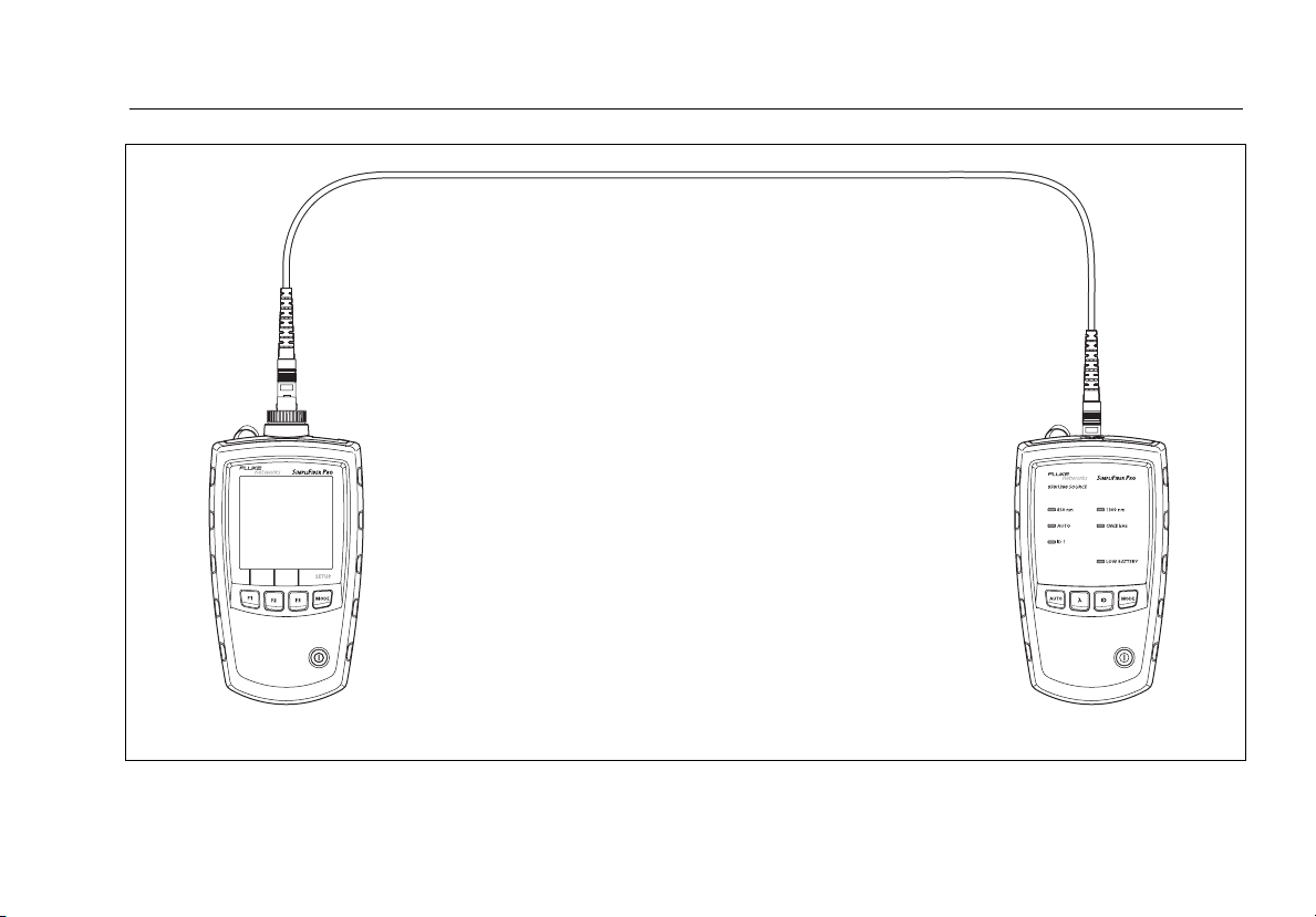
Make the connections shown Figure 10.
4
If the source’s AUTO LED is not on, press A.
If you want to set the reference for both wavelengths,
ss Z until the wavelength LEDs blink alternately.
pre
Note
If you are not using a SimpliFiber Pro source, set the
to the desired wavelength and continuous
source
wave output.
5
On the meter, press M until POWER appears (see
Figure 8 on page 23).
Notes
You cannot set the reference if Min or Ma
on the display. See page 24.
Setting the reference from power mode lets you
see the
reference level. You may also set the reference
from loss mode.
6
Press T SET REF. The meter switches to loss mode, the
display shows 0.00 dB, OK appears briefly, and the new
reference value appears.
If the reference value is less than -60 dBm or if the
source i
mode or try setting the reference again using another
tes
source’s power level before saving it as the
s in ID or 2 kHz mode, the meter briefly shows
and O. Check the connections and the source’s
t reference cord.
x appear
WCaution
If you disconnect the source’s output after setting
the reference, you must set the reference again to
ensure valid measurements.
26
Page 35
Measuring Loss
Test reference cord
WCaution
Do not disconnect the test
reference cord from the source’s
output after setting the reference
Meter Source
Figure 10. Reference Connections (1 Jumper method)
ffl07.eps
27
Page 36

SimpliFiber Pro Meter and Test Kits
Users Manual
Measuring Loss
1
Set the reference as described on page 25.
2
Clean the connectors on the link to be tested and on a
second test reference cord. Use fiber optic solvent and
optical-grade wipes or swabs to clean connectors as
described on page
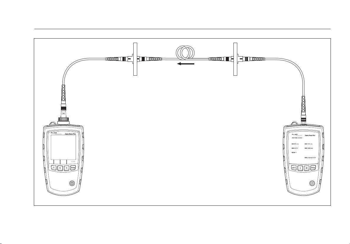
3
Disconnect the test reference cord from the meter;
then make the connections shown in Figure
15.
WCaution
Do not disconnect the test reference cord from the
source’s output. If you do, you must set the
reference again to ensure valid measurements.
4
On the meter, press M until LOSS appears (Figure 12).
5
If the source’s AUTO LED is not on, press A.
6
If you want the source to automatically switch
wavelengths, press Z until the wavelength LEDs blink
alternately. Or you may press
as needed.
Z to switch wavelengths
11.
Note
If you are not using a SimpliFiber Pro source, set the
source to the desired wavelength and to
continuous wave output. On the meter, press
to select the wavelength generated by the source.
7
To save the measurement, press R SAVE. The meter
briefly shows the record number and OK.
If the source was automatically switching wavelengths,
the meter saves measurements for all wavelengths in
one record.
S V
28
Page 37
Measuring Loss
Fiber linkSecond test
reference cord
Test reference cord
WCaution
Do not disconnect the test
reference cord from the source’s
output after setting the reference.
Meter Source
Figure 11. Loss Measurement Connections (1 Jumper method)
ffl08.eps
29
Page 38
SimpliFiber Pro Meter and Test Kits
A
C
E
B
D
F
Users Manual
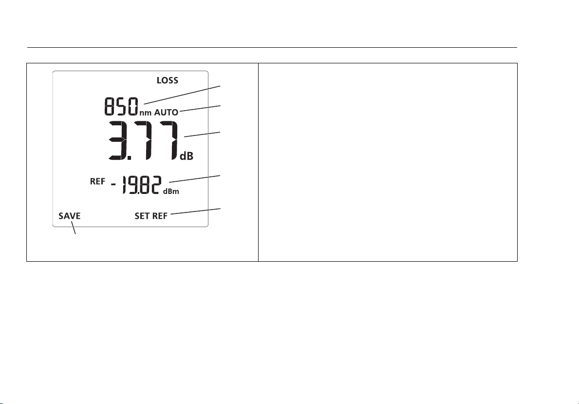
A The wavelength being measured.
B Indicates the meter is in auto wavelength mode.
C The loss measurement. If the loss measurement is blinking,
the loss is negative and less than -1.0 dB. See “If Loss is
Negative” on page 31.
D The reference value.
E Pressing T SET REF saves the measured power level as the
reference.
F Pressing R SAVE saves the measurement. If the source was
automatically switching wavelengths, the meter saves
measurements for all wavelengths in one record.
Figure 12. Loss Measurement Display
ffl17.eps
30
Page 39

Memory Functions
If Loss is Negative
A negative loss measurement means the reference power
level is less than the measured power level. This can be
caused by the following:
•
The fiber ends were dirty during referencing.
•
The connections to the source were disturbed after
referencing.
•
The was a kink in a test reference cord during
referencing.
•
The connectors were not properly aligned during
referencing.
•
The meter and source were not set to the same
wavelengths during referencing or testing.
•
The testers were much colder during referencing than
during testing.
•
You did not allow enough time for the source to warm
up before setting the reference.
•
You measured loss on a fiber that is shorter than the test
reference cord used to set the reference.
If loss is negative, set the reference again and retest the link.
Memory Functions
The meter stores up to 1000 loss or power records. If memory
is full, the meter shows when you try to save a
measurement.
Viewing and Deleting Records
To view records, press M until VIEW RECORD appears. See
Figure 13.
31
Page 40
SimpliFiber Pro Meter and Test Kits
B
D
C
Users Manual
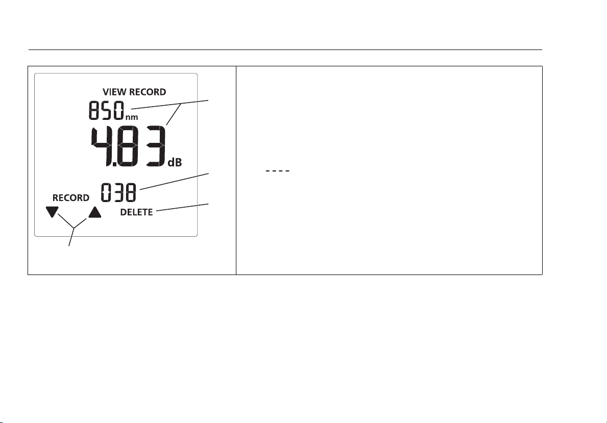
A The wavelength and the measurement. If the record contains
measurements for multiple wavelengths, the display alternates
A
between the measurements.
B The record number.
C To delete the record you are viewing, press T DELETE twice.
If you delete a record below the highest record number, the meter
does not reuse the empty memory location. Deleted records show
for the measurement.
To delete all records, hold down T DELETE until DELETE ALL?
appears; then press T again.
D Press R D or S E to scroll through records.
ffl21.eps
Figure 13. View Record Display
32
Page 41
Uploading Records to a PC
1
Install the latest version of LinkWare software on your
PC.
2
Turn on the meter.
3
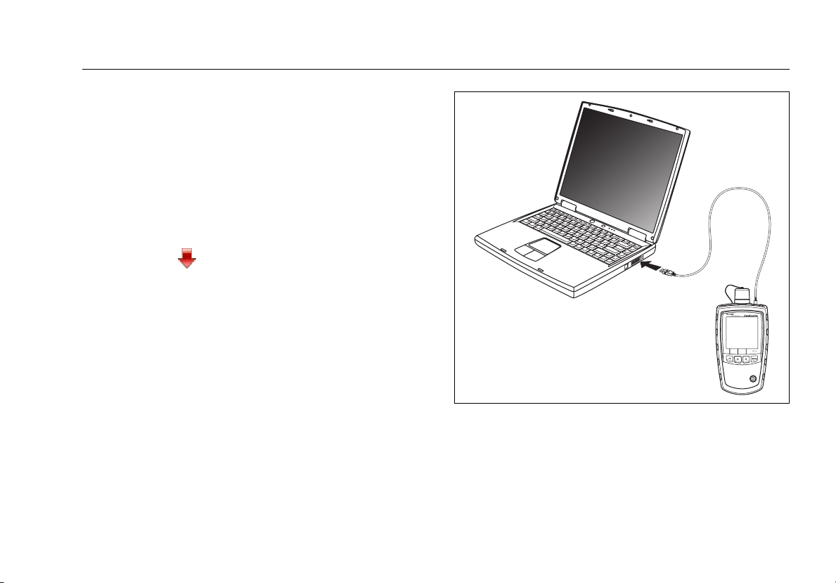
Connect the meter to the PC with the USB cable
provided, as shown in Figure 14.
4
Start LinkWare software on the PC.
5
Click Import on the LinkWare tool bar; then select
SimpliFiber Pro.
6
Enter project information; then click OK.
7
Import all records from the meter or select records to
import.
Note
The meter’s record numbers are in the Cable ID
mn in LinkWare.
colu
8
To delete all records in the tester, select Utilities >
SimpliFiber Pro > Delete All Tests in Memory.
Memory Functions
USB cable
ffl22.eps
Figure 14. Connecting to a PC
33
Page 42

SimpliFiber Pro Meter and Test Kits
Users Manual
Maintenance
WWarningX*
To avoid possible fire, electric shock, personal
injury, or damage to the tester:
•
Do not open the case. No user-serviceable parts are
inside.
•
Replacing electrical parts yourself will void the
tester’s warranty and might compromise its safety
features.
•
Use only specified replacement parts for userreplaceable items.
•
Use only Fluke Networks authorized service
centers.
Cleaning
Clean the display with glass cleaner and a soft, lint-free
cloth. Clean the case with a soft cloth dampened with
water or water and a mild soap.
WCaution
To avoid damaging the display or the case, do not
use solvents or abrasive cleansers.
Clean the optical connector as described on page 15.
Checking the Meter’s Software Version and Calibration Date
Turn the meter on while holding down the S and T keys.
Use
RD to toggle between the following:
•
SoF: Software version
•
FAC: Factory calibration date. The day and month
(DDMM) is on the top line, and the year (YYYY) is on
the bottom line.
To exit this mode, turn the meter off.
Options and Accessories
For a complete list of options and accessories visit the Fluke
Networks website at www.flukenetworks.com.
34
Page 43

Specifications
Environmental Specifications
Specifications
Operating temperature
Storage temperature
-10ºC to +50ºC
-20ºC to +50ºC
Meter Specifications
Detector type
Calibrated wavelengths
Measurement range
Power measurement linearity
Power measurement uncertainty
1. For 850 nm, ±0.2 dB for power from 0 dBm to -45 dBm, ±0.25 dB for power < -45 dBm.
2. ±0.1 dB for power from 0 dBm to -55 dBm. ±0.2 dB for power > 0 dBm and < -55 dBm.
3. 23°C ±2°C, power level -20
and 1625 nm; add 0.1 dB for 1625 nm.
3
dBm, continuous wave, 62.5/125 µm at multimode wavelengths, 9/125 µm at 1310 nm, 1490 nm, 1550 nm,
InGaAs
850 nm, 1300 nm, 1310 nm, 1490 nm, 1550 nm, 1625 nm
+10 dBm to -52 dBm (850 nm)
+10 dBm to -60 dBm (1300 nm, 1310 nm, 1490 nm, 1550 nm, 1625 nm)
±0.2 dB (850 nm)
1
±0.1 dB (1300 nm, 1310 nm, 1490 nm, 1550 nm, 1625 nm)
±0.25 dB
2
35
Page 44

SimpliFiber Pro Meter and Test Kits
Users Manual
Meter Specifications (cont.)
Display resolution, dB or dBm 0.01 dB
Power display units dBm, mW, µW
Auto-wavelength detection Yes
Record storage 1000 records, multiple wavelengths per record, sequential-number ID
External interface USB 2.0, full speed
Optical connector Removable adapter. SC adapter is standard. Optional adapters include LC, ST, FC
FindFiber ID detection Yes
Power requirement 2 AA alkaline batteries
Battery life
4
Automatic power-off 10, 20, 30, or 60 minutes (can be disabled by the user)
Low battery warning Low battery icon blinks
Size 6.4 in x 3.2 in x 1.5 in (16.5 cm x 8.0 cm x 3.9 cm)
Weight 11.5 oz (325 g)
4. Measured power levels ≤0 dBm. Battery life depends on the condition and type of batteries used. Fluke Networks recommends alkaline
batteries.
>50 hours (typical)
36
Page 45

Multimode Source
Specifications
Emitter type
Central wavelength
Spectral width (FWHM)
Minimum output power
Power output stability
1
Auto dual-wavelength switching
Optical output connector
FindFiber ID generation
Modes
1. 23°C ±2°C, after 5 minutes of warm-up time.
LED: dual 850 nm/1300 nm
850 nm: ±30 nm
1300 nm: ±20 nm
850 nm: 50 nm (typical)
1300 nm: 170 nm (maximum)
850/1300 nm: ≥ -20 dBm
±0.1 dB over 8 hours
Yes. Can be enabled or disabled by the user.
Fixed SC
Yes. Fixed at ID 1.
CW (continuous wave), 2 kHz modulated, auto-wavelength
37
Page 46

SimpliFiber Pro Meter and Test Kits
Users Manual
Multimode Source (cont.)
Power requirement 2 AA alkaline batteries
Battery life
Automatic power off 30 minutes (can be disabled by the user)
Low battery warning LED blinks
Size 5.6 in x 3.2 in x 1.6 in (14.2 cm x 8.1 cm x 4.1 cm)
Weight 9.8 oz (278 g)
2. In auto-wavelength mode. Battery life depends on the condition and type of batteries used. Fluke Networks recommends alkaline
batteries.
2
40 hours (typical)
38
Page 47

1310 nm/1550 nm Singlemode Source
Specifications
Emitter type
Central wavelength
Spectral width (RMS)
Minimum output power
Power output stability
1
Auto dual-wavelength switching
Optical output connector
FindFiber ID generation
Modes
1. 23°C ±2°C, after 5 minutes of warm-up time.
FP laser: dual 1310 nm/1550 nm
1310 nm: ±20 nm
1550 nm: ±30 nm
1310 nm: 2 nm (maximum)
1550 nm: 3 nm (maximum)
1310 nm/1550 nm: ≥ -7 dBm (typical)
±0.25 dB over 8 hours
Yes. Can be enabled or disabled by the user.
Fixed SC
Yes. Fixed at ID 2.
CW (continuous wave), 2 kHz, auto-wavelength
39
Page 48

SimpliFiber Pro Meter and Test Kits
Users Manual
1310 nm/1550 nm Singlemode Source (cont.)
Power requirement 2 AA alkaline batteries
Battery life
Automatic power off 30 minutes (Can be enabled or disabled by the user.)
Low battery warning LED blinks
Size 5.6 in x 3.2 in x 1.6 in (14.2 cm x 8.1 cm x 4.1 cm)
Weight 9.8 oz (278 g)
2. In auto-wavelength mode. Battery life depends on the condition and type of batteries used. Fluke Networks recommends alkaline
batteries.
2
30 hours (typical)
40
Page 49

1490 nm/1625 nm Singlemode Source
Specifications
Emitter type
Central wavelength
Spectral width (RMS)
Minimum output power
Power output stability
1
Auto dual-wavelength switching
Optical output connector
FindFiber ID generation
Modes
1. 23°C ±2°C, after 5 minutes of warm-up time.
DFB laser: dual 1490 nm/1625 nm
1490 nm: ±3 nm
1625 nm: ±5 nm
1490 nm: 1 nm (maximum)
1625 nm: 1 nm (maximum)
1490 nm/1625 nm: ≥ -3 dBm (typical)
±0.25 dB over 8 hours
Yes. Can be enabled or disabled by the user.
Fixed SC
Yes. Fixed at ID 3.
CW (continuous wave), 2 kHz, auto-wavelength
41
Page 50

SimpliFiber Pro Meter and Test Kits
Users Manual
1490 nm/1625 nm Singlemode Source (cont.)
Power requirement 2 AA alkaline batteries
Battery life
Automatic power off 30 minutes (Can be enabled or disabled by the user.)
Low battery warning LED blinks
Size 5.6 in x 3.2 in x 1.6 in (14.2 cm x 8.1 cm x 4.1 cm)
Weight 9.8 oz (278 g)
2. In auto-wavelength mode. Battery life depends on the condition and type of batteries used. Fluke Networks recommends alkaline
batteries.
2
30 hours (typical)
42
Page 51

FindFiber Source Specifications
Specifications
Emitter type
Source connector
FindFiber ID numbers
Power indicator
Power requirement
Battery life
Automatic power-off
Low battery indicator
Size
Weight
Laser
Fixed SC
1 through 8. Default is 3.
LED
2 AA alkaline batteries
>80 hours (typical)
30 minutes
Blinking LED
in x 1.3 in x 1.0 in (17.9 cm x 3.2 cm x 2.5 cm)
7.1
4.4 oz (125 g)
43
Page 52

SimpliFiber Pro Meter and Test Kits
Users Manual
Certifications, Compliance, and Regulatory Information
P
;
)
Laser
safety
44
Conforms to relevant European Union
directives
Conforms to relevant Australian standards
Listed by the Canadian Standards Association
Complies with 21CFR.1040.10,11, and EN60825-1,
2:2007 (Class 1, Hazard Level 1)
Page 53

Appendix A: How to Test Your Test Reference Cords
Why You Must Do this Test
To get accurate measurements of loss, you must use highquality test reference cords that are in good condition and
comply with ISO/IEC 14763-3. Measurements of optical
power loss are very much affected by the condition of the
endfaces on the fiber connectors. Dirty endfaces and
endfaces with damage are the most common causes of
problems in fiber links.
When You Must Do this Test
Test your test reference cords at these times:
•
At the start of each day
•
When you move your equipment to a different area
•
When you change your equipment to test links that
have a different type of connector
After you do the test given in this Appendix, use the
procedure given with the procedures for certifying cabling
to monitor the condition of the cords.
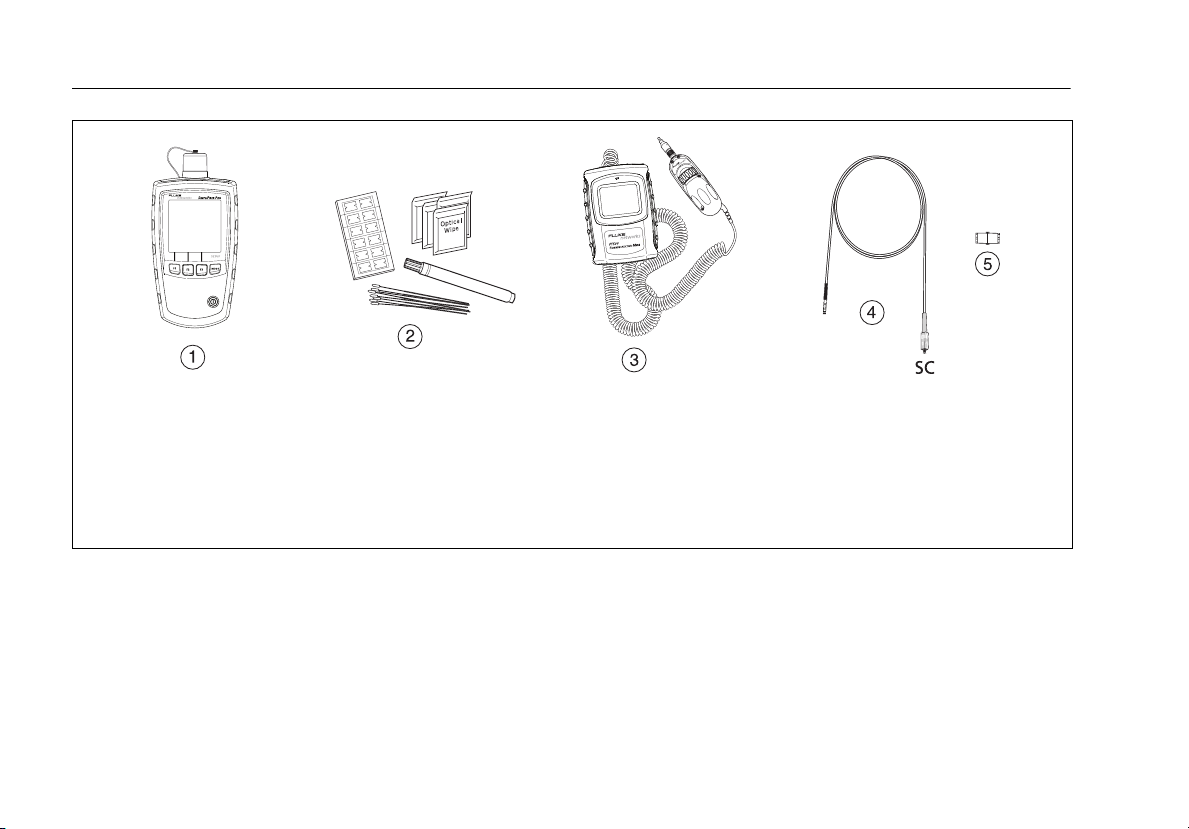
Equipment You Must Have
Figure A-1 shows the equipment you must have to test
your test reference cords.
WCaution
To do this procedure, you must have a fiber
microscope. You cannot be sure that your cords
are good unless you can examine the endfaces
on the connectors. An endface that is dirty or
has damage can give a good loss measurement,
but can cause problems later. See Figure
A-2.
45
Page 54
SimpliFiber Pro Meter and Test Kits
Users Manual
A
SimpliFiber Pro optical power meter. Use the connector
adapter that connects to the cords you will test.
B
Fiber cleaning supplies
C
A microscope for inspecting fiber connectors (the FT500
FiberInspector Mini Video Microscope is shown)
Figure A-1. Equipment for Testing the Test Reference Cords
D
A test reference cord that you are sure is good. One
connector is SC. The other connector is the same as on
the cords you will test.
E
Singlemode adapter for the connectors on the cords
you will test
ffl24.eps
46
Page 55
1 Clean and Inspect the Connectors
1-1
Test reference cords must have endfaces that are clean
and have no damage. Always use correct procedures to
clean endfaces. See page 15 or use the procedures
given with your cleaning supplies.
Appendix A: How to Test Your Test Reference Cords
1-2
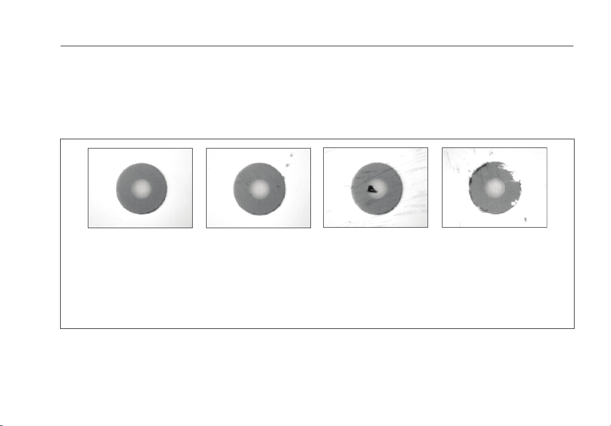
After you clean an endface, use a fiber microscope to
examine the endface. Figure A-2 shows examples of
what you can see with a fiber microscope.
AB
A
A clean endface that has no damage. This is the only
condition that you can accept for a test reference cord.
B
Dirt that is not on the core does not change the loss
measurement, but the dirt can move when you connect
the fiber.
Figure A-2. Examples of Fiber Endfaces
CD
C
Dirt is on the core. Also, there are scratches that were
caused by incorrect procedures for cleaning.
D
The cladding has damage. This does not change the loss
measurement, but can cause damage to other endfaces.
amd172.eps
47
Page 56

SimpliFiber Pro Meter and Test Kits
Users Manual
2 Set the Reference
2-1
Set the reference as described on page 26.
2-2
Make sure that the reference value is good:
•
For 50/125 µm fiber, the reference value must be
better than -24.50 dBm (for example, -23.50 dBm is a
better value)
•
For 62.5/125 µm fiber, the reference value must be
better than -20.00 dBm (for example, -19.50 dBm is a
better value)
•
For 9/125 µm fiber, the reference value must be
better than -8.00 dBm (for example, -7.50 dBm is a
better value)
If the value is not good, do the reference procedure
again with a different test reference cord.
3 Test the Cord in Both Directions
3-1
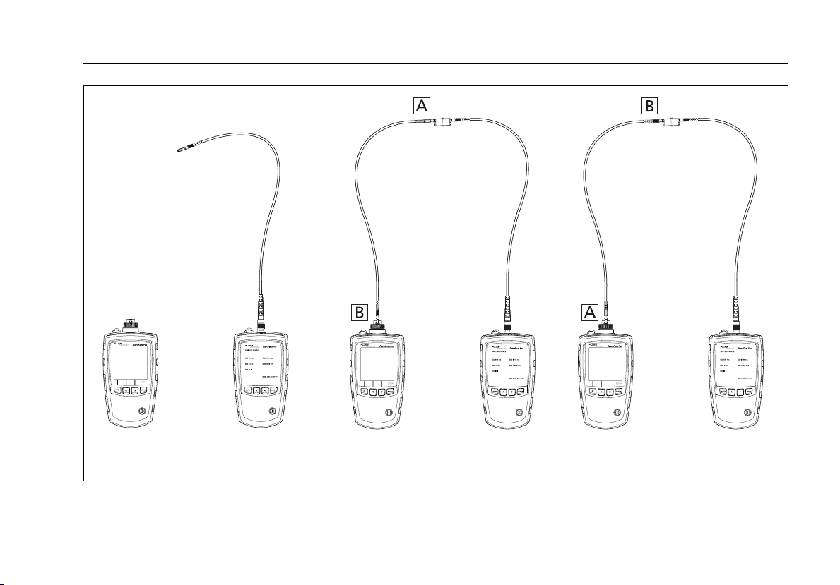
Disconnect the test reference cord from the meter
A
(Figure A-3,
3-2
Connect the cord you want test (Figure A-3, B).
).
3-4
If the source’s AUTO LED is not on, press A.
3-5
If you want the source to automatically switch
wavelengths, press
blink alternately. Or you may press Z to switch
wavelengths as needed.
If you are not using a SimpliFiber Pro source, set
the source to the desired wavelength and to
continuous wave output. On the meter, press S V
to select the wavelength generated by the source.
3-6
Compare the loss measurement to these limits:
•
Multimode test reference cord: 0.10 dB or less
•
Singlemode test reference cord: 0.20 dB or less
If the connectors show no contamination or damage,
but the loss is higher than these limits, the cord does
not comply with ISO/IEC 14763-3. Do not use the cord
as a test reference cord.
3-7
Connect the cord in the opposite direction (Figure A-3,
C
), then repeat step 3-6.
Z until the wavelength LEDs
Note
3-3
On the meter, press M until LOSS appears.
48
Page 57
Appendix A: How to Test Your Test Reference Cords
.
ABC
Figure A-3. Connections for Testing a Test Reference Cord
ffl25.eps
49
Page 58

SimpliFiber Pro Meter and Test Kits
Users Manual
50
Page 59

Appendix B: Using Mandrels
You should use mandrels when testing multimode fiber.
Mandrels can improve measurement repeatability and
consistency. They also allow the use of LED light sources to
certify 50 µm and 62.5 µm fiber links for current and planned
high bit-rate applications, such as Gigabit Ethernet and
10 Gigabit Ethernet. Mandrels are available from Fluke
Networks.
WCaution
Do not use mandrels when testing singlemode
fiber.
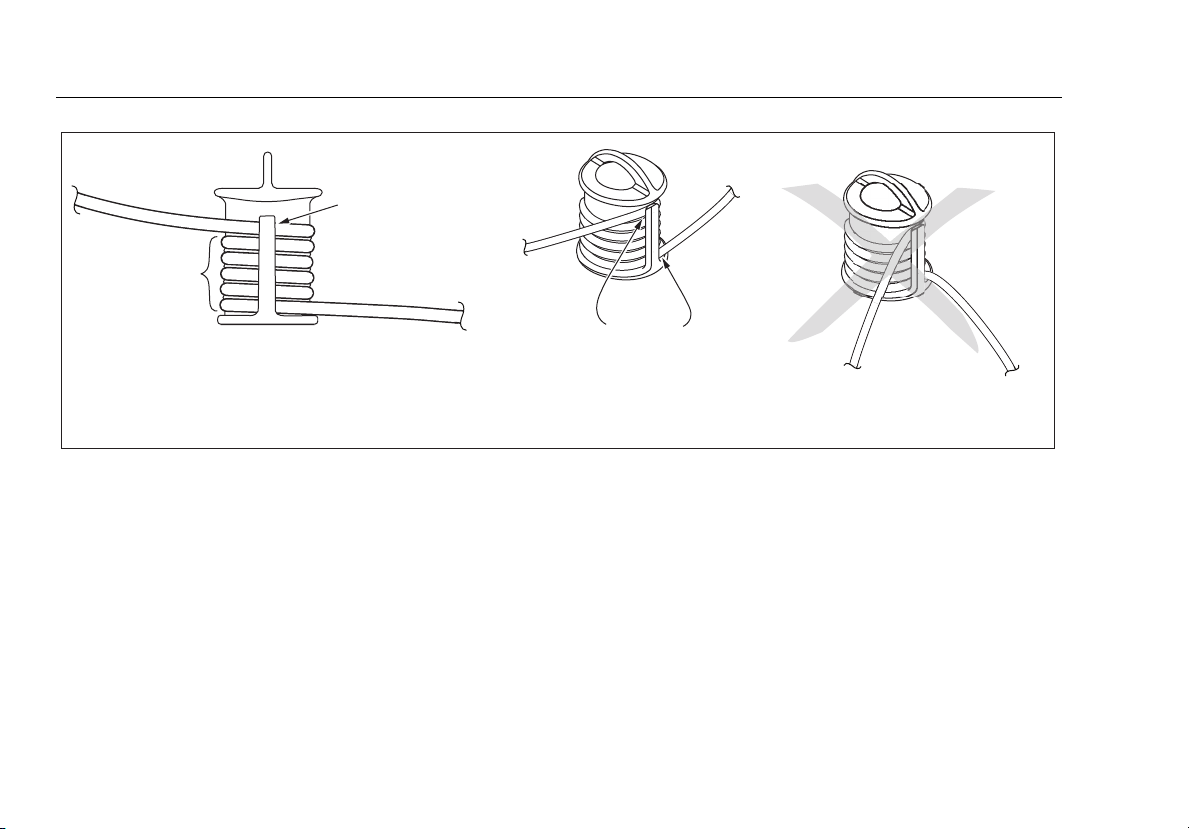
Figure B-1 shows how to wrap the fiber around a mandrel.
Place the mandrel at the source’s output, as shown in Figure
B-2.
51
Page 60
SimpliFiber Pro Meter and Test Kits
Users Manual
Wrap 5 times
in grooves
Figure B-1. Wrapping a Test Reference Cord Around a Mandrel
Place top wrap
in groove under
retainer
Right:
no bends
at retainer
Wrong:
bends at
retainer
amd67.eps
52
Page 61
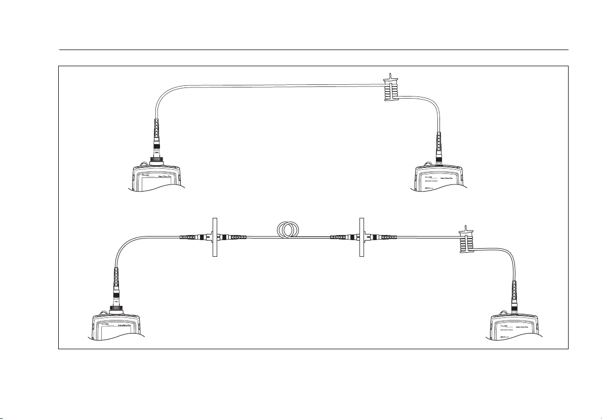
Reference connections
Test connections
Appendix B: Using Mandrels
Figure B-2. Mandrel Placement
ffl16.eps
53
Page 62

SimpliFiber Pro Meter and Test Kits
Users Manual
54
Page 63

Appendix C: Fiber Test Method Names
Industry standards use different names for equivalent fiber
test methods. Table C-1 shows the names used in this
manual and by four common industry standards for the
three fiber test methods.
Table C-1. Test Method Names
Link End Connections
Included in Loss Results
1 connection 2 Jumper Method A Method A.2 Method 1 Method A2
2 connections 1 Jumper Method B Method A.1 Method 2 Method A1
None 3 Jumper Method C Method A.3 Method 3 Method A3
This
Manual
TIA/EIA-526-14A
(multimode)
TIA/EIA-526-7
(singlemode)
IEC 61280-4-1
(multimode)
IEC 61280-4-2
(singlemode)
55
Page 64

SimpliFiber Pro Meter and Test Kits
Users Manual
56
Page 65

Appendix D: Loss Test Methods
Introduction
The number of fiber connections represented in loss test
results depends on the reference and test connections. This
appendix describes the three common methods: 1 Jumper,
2 Jumper, and 3 Jumper.
Note
See Appendix C for a cross-reference of the method
names in various standards.
This appendix also describes modified connections you can
use if you do not have the correct connector adapters for the
meter.
57
Page 66

SimpliFiber Pro Meter and Test Kits
Users Manual
1 Jumper Method
Results from the 1 jumper method account for the loss of
two connections plus the fiber in the link. This method is
suitable for testing premises fiber, where patch cords are
typically used at both ends of the link and connector loss is a
significant portion of the total loss.
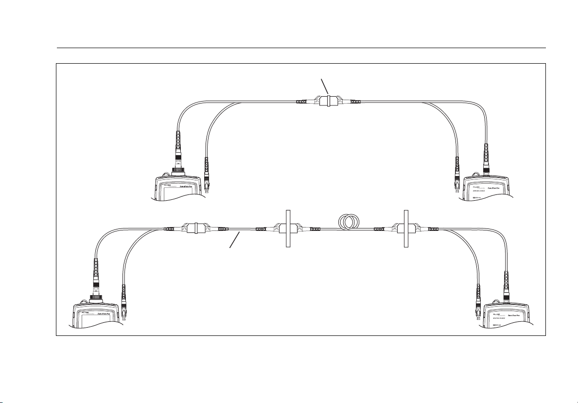
1 jumper reference connections cancel out the effects of the
test reference cords, as shown in Figure D-1.
Loss results for the1 jumper method therefore represent
both connections plus the fiber in the link. ANSI/TIA/EIA-52614A and 526-7 specify the1 jumper method for testing
multimode and singlemode premises fiber, where connector
loss is a significant portion of the total loss.
Note
To get 1 jumper results when you do not have the
correct connector adapters for the meter, see
“Modified 1 Jumper Method” on page
64.
58
Page 67
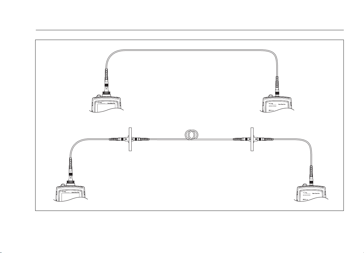
Reference connections
Fiber link
Test connections
Appendix D: Loss Test Methods
Figure D-1. Reference and Test Connections for the 1 Jumper Method
ffl11.eps
59
Page 68

SimpliFiber Pro Meter and Test Kits
Users Manual
2 Jumper Method
Results from the 2 jumper method account for the loss of
one connection plus the fiber in the link. This method is
suitable for links where the fiber's loss is a significant portion
of the total loss, such as when the link is long or a patch cord
is used at only one end.
2 jumper reference connections cancel out the effects of one
connection and two test reference cords, as shown in Figure
D-2.
The test connections add one connection, plus the fiber in
the link, to each path. Loss results for the 2 jumper method
therefore represent only one connection plus the fiber in the
link.
Because the results omit one connection, ANSI/TIA/EIA-52614A and 526-7 do not recommend the 2 jumper method for
testing premises fiber, where patch cords are typically used at
both ends of a link and connector loss is a significant portion
of total loss.
60
Page 69
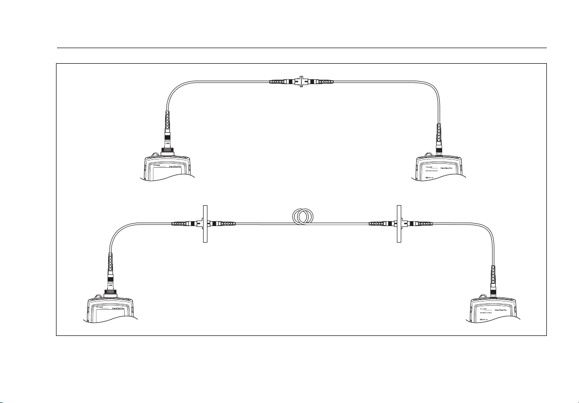
Reference connections
Fiber link
Test connections
Appendix D: Loss Test Methods
Figure D-2. Reference and Test Connections for the 2 Jumper Method
ffl10.eps
61
Page 70

SimpliFiber Pro Meter and Test Kits
Users Manual
3 Jumper Method
Results from the 3 jumper method account for the loss of
only the fiber in the link. This method is suitable for testing
links where the fiber's loss is the majority of the total loss,
such as when the link is very long or patch cords are not used
at either end.
3 jumper reference connections cancel out the effects of two
connections and the test reference cords, as shown in Figure
D-3.
The test connections add only the fiber in link. Loss results
for the 3 jumper method therefore represent only the fiber
in the link.
Because the results omit both connections in the link, ANSI/
TIA/EIA-526-14A and 526-7 do not recommend the 3 jumper
method for testing premises fiber, where patch cords are
typically used at both ends of the link and connector loss is a
large portion of the total loss.
62
Page 71
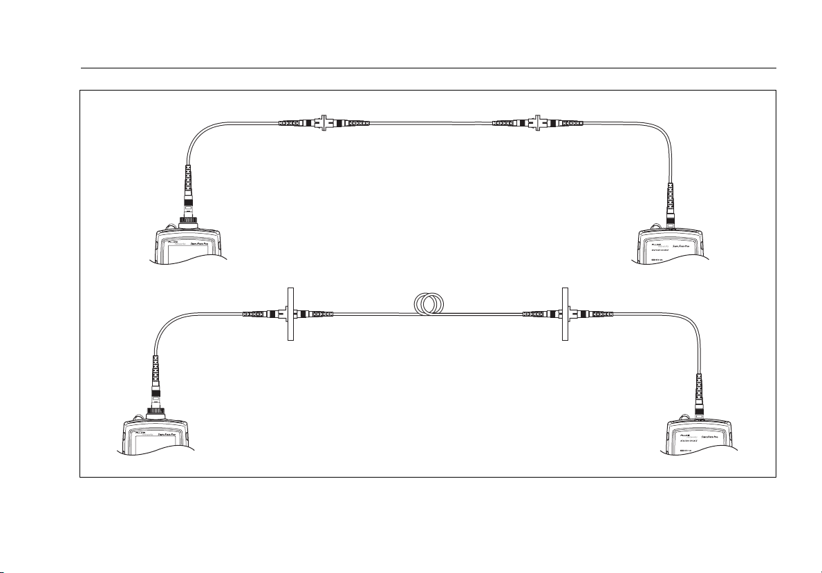
Reference connections
Fiber link
Test connections
Appendix D: Loss Test Methods
Figure D-3. Reference and Test Connections for the 3 Jumper Method
ffl12.eps
63
Page 72

SimpliFiber Pro Meter and Test Kits
Users Manual
Modified 1 Jumper Method
This section describes modified reference and test
connections that produce 1 jumper results. Use these
connections if you need 1 jumper results but do not have
connector adapters that match the connectors on the link.
This method lets you connect to the link without disturbing
the source’s output connections after setting the reference.
Figure D-4 shows reference and test connections for one
fiber in a duplex cable with LC connectors.
64
Page 73
SC to LC test
reference cord
Short LC to LC
test reference cord.
(0.3 m or less. Added
after referencing.)
Appendix D: Loss Test Methods
LC to LC adapter
SC to LC test
reference cord
Reference connections
Fiber link
Test connections
Figure D-4. Reference and Test Connections for the Modified 1 Jumper Method
ffl13.eps
65
Page 74

SimpliFiber Pro Meter and Test Kits
Users Manual
66
Page 75

Index
–1–
1 jumper method, 25, 58
modified, 64
1, 2, 3 jumper, 57
–2–
2 kHz modulated mode, 14
–A–
accessories
optional, 34
standard, 4
AUTO, 14
auto power-off, 13
auto wavelength mode, 14
–B–
backlight, 13
batteries, 7
–C–
calibration date, 34
cautions, 3
certifications and compliance, 44
CheckActive mode, 18
cleaning
connectors and adapters, 15
display and case, 34
connections
1 jumper method, 58
modified, 64
3 jumper method, 62
fiber loss test methods, 57
locating fibers, 21
loss measurement, 29
PC, 33
power measurement, 22
reference, 27
connector adapter, 16
connectors, 9
continuous wave mode, 14
customer support, 2
CW/2 kHz, 14
–D–
deleting records, 32, 33
detecting active fibers, 18
display features, 10
–F–
FindFiber mode, 20
Fluke Networks
contacting, 2
Knowledge Base, 2
67
Page 76

SimpliFiber Pro Meter and Test Kits
Users Manual
–H–
help (contacting Fluke Networks), 2
–I–
ID, 20
–K–
keys, 9
Knowledge Base, 2
–L–
locating fibers, 20
loss
display, 30
measuring, 28
negative, 31
setting the reference, 25
test methods, 57
–M–
maintenance, 34
mandrels, 51
memory, 31
method names, 55
minimum/maximum (Min/Max), 24
–N–
negative loss, 31
–O–
options, 34
–P–
PC connections, 33
power
auto power-off, 13
display, 23
measuring, 22
minimum/maximum (Min/Max),
24
unit of measurement, 13
–R–
records
number, 32
uploading to a PC, 33
viewing and deleting, 31
reference
about referencing, 25
fail, 26
setting the reference, 25
registration, 1
–S–
safety information, 2, 34
setting the reference, 25
setup, 12
specifications, 35
–T–
test reference cord
how to test, 45
–U–
uploading records to a PC, 33
–V–
version, 34
VIEW RECORD display, 32
68
 Loading...