

Page 1
APPLICATION NOTE
LED Chip Heat
Dissipation Mapping
The LED chip is the core component of
LED lighting. If the chip temperature is
too high, the LED life and luminous quality
could be severely affected.
What is a heat sink and
why is it important?
A heat sink is a common component in many electronic devices.
It transfers the heat created by
a device, acting to reduce the
device’s temperature to prevent
overheating. Heat sinks are an
important part of LED lighting,
more specifically LED chips. The
heat sink aids in heat dissipation of the chip, ensuring that
the temperature of these chips
stays within the appropriate
range. Testing heat sinks in the
production process of LED chips
is critical to ensuring quality.
Infrared cameras can be used in
the R&D process to check LED
heat sinks. The readings from a
camera can help manufacturers
find potential problems with
materials and designs, to better
analyze and improve heat sink
qualit y.
Relationship between the
LED chip temperature and
the heat sink
To continue operating properly, LED chip temperature
should not exceed 120 °C. As
chip temperature increases,
the unfortunate reality is that
service life decreases. So, if the
chip temperature is very high,
or even worse, exceeds 120 °C,
service life of the chip will be
shortened.
Therefore it is important to
stay below 120 °C to maintain
chip performance and service
capability. This emphasizes the
importance of the heat sink—the
heat sink is what cools the LED
chip. If the heat sink is unavailable, poorly designed, or made
of improper material, the heat
dissipation effect will be seriously affected, thus shortening
the LED service life or resulting
in a change of LED color.
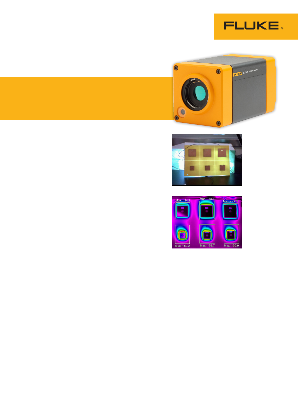
CASE:
We worked with the R&D
department for a large LED manufacturer to understand how LED
chips are tested. The manufacturer stated the importance of
the heat dissipation effect and
heat sink size when designing
a heat dissipation scheme for
the chip. Six types of heat sinks
were designed for research.
As shown in Figure 1, the heat
sink area increases as you
move from bottom left to top
right. These figures have the
same chip under the same input
voltage, current and the same
lighting time.
In Figure 2, the temperature
at the upper middle position is
48.1 °C, inconsistent with the
temperature trend of heat sink
size. Normally the estimated
value should be in the range of
43 °C to 44 °C. Since we see in
the figure that the temperature
falls outside of this range, it is
likely that the design or material selection of the heat sink
here is flawed. The image can
also be used to calculate the
heat dissipation per unit area by
focusing on the area size and
Figure 1
Figure 2
temperature. In this example, it
is clear that the design at the
lower right corner has the worst
heat dissipation effect, and the
upper right corner shows the
best heat dissipation effect.
Page 2
Before an infrared camera,
what was used to measure
the temperature during
heat dissipation R&D of an
LED chip?
Before the introduction of infrared cameras, a thermocouple
was the most popular way to
measure temperature during
heat dissipation.
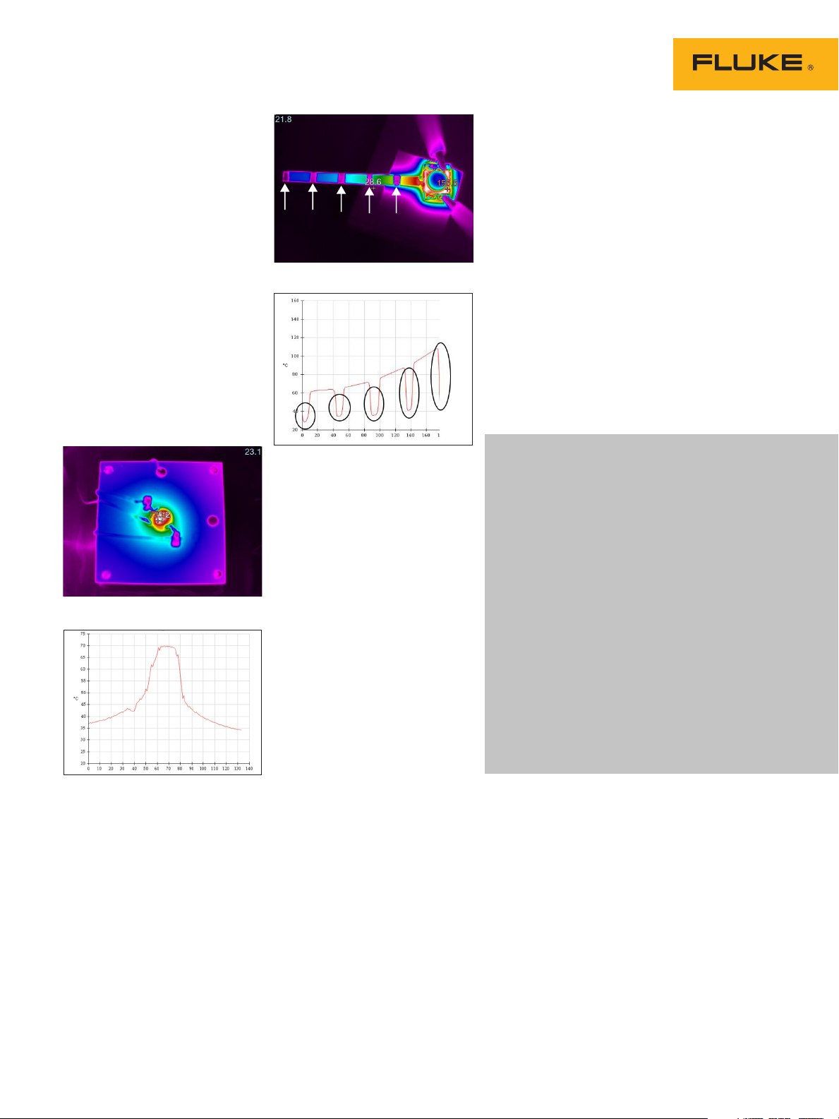
In Figure 3A the LED chip
(circular part) uses a strip-like
heat sink, and Fluke SmartView®
desktop reporting and analysis software is used to perform
linear analysis for the temperature distribution at different
distances as seen in Figure 3B.
In Figure 4A there are metal
bands (purple color on the heat
Metal bands
Figure 4A
What are the advantages of
the infrared camera?
The infrared camera can quickly
test the performance of the radiation fin. The online monitoring
and real-time shooting thermal
map features can be used to
conduct specific temperature
analysis of the fin on a PC. An
infrared camera is a non-contact
form of temperature measurement which decreases the time
it takes to measure the apparent
temperature and is more accurate. The temperature profile of
the heat sink with other related
analysis functions is of major
importance to help optimize the
heat sink design thus prolonging
the LED chip life.
Figure 3A
Figure 3B
Figure 4B
sink) segmented on the striplike heat sink. This is causing
the temperature of these segments to be low due to the low
emissivity. This is seen on the
graph (Figure 4B) where the
temperature drops down, highlighted by the black circles.
What are the disadvantages
of using the thermocouple
for testing?
The thermocouple has a few
limitations. The first disadvantage of using a thermocouple is
that it must make contact with
the surface to take a measurement. To be able to make
contact there must be a surface
placed over the heat sink using
glue which can alter the temperature reading. In addition
when using a thermocouple you
can only take a point measurement. This means that only a
singular point of the heat sink
is tested which does not provide an accurate reading for the
whole heat sink.
When you are performing tests
make sure to keep accuracy as
a priority. Here are three things
to keep in mind for better LED
inspections.
1. The metal material emissivity of
some heat sinks leads to a low temperature reading. To avoid incorrect
measurements, apply silicone grease
or paint to the radiation fin.
2. Given the different sizes of various
LED heat sinks, an add-on macro
lens can help provide more detailed
and accurate readings.
3. When using the camera for LED
inspections look down upon the
items being inspected and not from
an angle.
2 Fluke Corporation LED Chip Heat Dissipation Detection
Page 3

See what you’re missing
Whether you’re designing the next mobile
device, scaling down passenger vehicles,
or developing a new stronger, lighter polymer,
make sure you have the best thermal data you
can get. For accurate and efficient R&D infrared
testing, we recommend the Fluke RSE series—
RSE300 and RSE600 Infrared Cameras. With
down to 40mK thermal sensitivity, and up to
640 x 480 resolution, these mounted cameras
stream data to your PC for R&D and quality
assurance analysis.
To find out more about how these versatile,
high resolution, high accuracy cameras
can help you develop better products faster,
consult your Fluke sales representative or
visit www.fluke.com/infrared for more
information.
Fluke. Keeping your world
up and running.
Fluke Corporation
PO Box 9090, Everett, WA 98206 U.S.A.
Fluke Europe B.V.
PO Box 1186, 5602 BD
Eindhoven, The Netherlands
For more in formation ca ll:
In the U.S.A. (800) 443-5853 or
Fax (425) 446-5116
In Europe/M-East/Afr ica +31 (0)40 267 5100 or
Fax +31 (0)40 267 5222
In Canada (800)-36-FLU KE or
Fax (905) 890-6866
From other countries +1 (425) 446-5500 or
Fax +1 (425) 446-5116
Web access: http://www.fluke.com
©2018 Fluke Cor porat ion. A ll trademarks are t he
proper ty of their respective ow ners. Data subject to
change without notice. 3/ 2018 6010 58 2a-e n
Modi ficat ion of th is doc ument is not per mitte d
without wri tten pe rmis sion from Fluk e Corpo ration .
®
3 Fluke Corporation LED Chip Heat Dissipation Detection
 Loading...