

Page 1

RPM4-AD™
Reference Pressure Monitor, Air Data Version
Operation and Maintenance Manual
© 2005-2007 DH Instruments, a Fluke Company
Page 2

High pressure liquids and gases are potentially hazardous. Energy stored in these liquids and gases
can be released unexpectedly and with extreme force. High pressure systems should be assembled
and operated only by personnel who have been instructed in proper safety practices.
This instrument is not to be operated in any other manner than that specified by the manufacturer.
© 2005-2007 DH Instruments, a Fluke Company All rights reserved.
Information in this document is subject to change without notice. No part of this document may be reproduced or transmitted in any
form or by any means, electronic or mechanical, for any purpose, without the express written permission of DH Instruments, a
Fluke Company 4765 East Beautiful Lane, Phoenix AZ 85044-5318, USA.
DH Instruments makes sincere efforts to ensure accuracy and quality of its’ published materials; however, no warranty, expressed
or implied, is provided. DH Instruments disclaims any responsibility or liability for any direct or indirect damages resulting from the
use of the information in this manual or products described in it. Mention of any product or brand does not constitute an
endorsement by DH Instruments of that product or brand. This manual was originally composed in English and was subsequently
translated into other languages. The fidelity of the translation cannot be guaranteed. In case of conflict between the English version
and other language versions, the English version predominates.
Products described in this manual are manufactured under international patents and one or more of the following U.S. patents:
5,142,483; 5,257,640; 5,331,838; 5,445,035. Other U.S. and international patents pending.
AutoRange, AutoZ, DH Instruments, DH, DHI, CalTool, COMPASS, parallel measurement mode, //m mode, RPM4, QDUT, Q-RPT,
RPM4-AD and SDS are trademarks, registered and otherwise, of DH Instruments, a Fluke Company
Document No. 550148
051115
Printed in the USA.
© 2005-2007 DH Instruments, a Fluke Company
Page 3

TABLE OF CONTENTS
T
AABBLLEE
T
O
O
FF
C
OONNTTEENNTTS
C
S
TABLE OF CONTENTS ...............................................................I
TABLES ..................................................................................V
FIGURES................................................................................VI
ABOUT THIS MANUAL ............................................................VII
1. INTRODUCTION
1.1 PRODUCT OVERVIEW ...........................................................................................................................1
1.2 SPECIFICATIONS ...................................................................................................................................2
1.2.1 GENERAL SPECIFICATIONS....................................................................................................................... 2
1.2.2 PRESSURE MEASUREMENT SPECIFICATIONS........................................................................................2
1.2.2.1 QUARTZ REFERENCE PRESSURE TRANSDUCERS (Q-RPT)..............................................................2
1.2.2.2 ON-BOARD BAROMETER ........................................................................................................................4
1.2.3 BATTERY AND CHARGER PACK ................................................................................................................4
................................................................. 1
2. INSTALLATION .................................................................. 5
2.1 UNPACKING AND INSPECTION ............................................................................................................5
2.1.1 REMOVING FROM PACKAGING..................................................................................................................5
2.1.2 INSPECTING CONTENTS.............................................................................................................................5
2.2 SITE REQUIREMENTS............................................................................................................................6
2.3 SETUP .....................................................................................................................................................6
2.3.1 PREPARING FOR OPERATION ...................................................................................................................6
2.3.2 FRONT AND REAR PANELS ........................................................................................................................ 6
2.3.2.1 FRONT PANEL ..........................................................................................................................................6
2.3.2.2 REAR PANEL.............................................................................................................................................7
2.3.3 POWER CONNECTION................................................................................................................................. 7
2.3.3.1 85 TO 264 VAC, 50/60 HZ VAC POWER ..................................................................................................7
2.3.3.2 BATTERY PACK ........................................................................................................................................7
2.3.4 REMOTE [ENT] CONNECTION (FOOTSWITCH OR OTHER SWITCH)...................................................... 8
2.3.5 CONNECTING TO MEASURE PRESSURE (PS AND PT PORTS)..............................................................8
2.3.6 THE VENT AND ATM PORTS....................................................................................................................... 9
2.3.7 CHECK/SET SECURITY LEVEL ...................................................................................................................9
2.3.8 SDS FULL TIME OFF ....................................................................................................................................9
2.4 POWER-UP AND VERIFICATION.........................................................................................................10
2.4.1 SWITCH POWER ON ..................................................................................................................................10
2.4.2 CHECK PRESSURE MEASUREMENT OPERATION.................................................................................10
2.4.2.1 CHECKING ABSOLUTE MODE PRESSURE MEASUREMENT.............................................................10
2.4.2.2 CHECKING GAUGE MODE PRESSURE MEASUREMENT...................................................................10
2.5 SHORT TERM STORAGE ..................................................................................................................... 11
3. OPERATION
3.1 USER INTERFACE ................................................................................................................................13
3.1.1 MAIN RUN SCREEN....................................................................................................................................13
3.1.2 FUNCTION / DATA KEYPAD LAYOUT AND PROTOCOL.........................................................................15
3.1.3 REMOTE [ENT] (ENTER) FOOTSWITCH...................................................................................................16
3.1.4 SOUNDS ......................................................................................................................................................16
Page I © 2005-2007 DH Instruments, a Fluke Company
..................................................................... 13
Page 4

RPM4-AD™ OPERATION AND MAINTENANCE MANUAL
3.2 GENERAL OPERATING PRINCIPLES .................................................................................................16
3.2.1 Q-RPTS AND Q-RPT SELECTION..............................................................................................................16
3.2.2 GAUGE AND NEGATIVE GAUGE MEASUREMENT, DYNAMIC COMPENSATION
FOR ATMOSPHERIC PRESSURE..............................................................................................................17
3.2.3 ALTITUDE AND AIRSPEED MEASUREMENT...........................................................................................18
3.2.3.1 RPM4-AD A160K/A160K (ROTARY WING).............................................................................................18
3.2.3.2 RPM4-AD A350K/A160K (FIXED WING)................................................................................................. 19
3.2.4 PRESSURE READY/NOT READY ..............................................................................................................20
3.2.5 PARALLEL MEASUREMENT MODE (//MTM) (RPM4-AD A160K/A160K ONLY) .......................................20
3.2.6 DIFFERENTIAL MEASUREMENT MODE...................................................................................................21
3.2.7 AUTOZERO FUNCTION..............................................................................................................................21
3.2.8 SDS SELF DEFENSE SYSTEM ..................................................................................................................21
3.2.9 USE OF THE 12VDC BATTERY/CHARGER PACK ...................................................................................22
3.2.10 USING RPM4-AD WITH A PPC3 CONTROLLER/CALIBRATOR ..............................................................23
3.2.11 DIRECT FUNCTION KEYS SUMMARY ......................................................................................................23
3.3 DIRECT FUNCTION KEYS ....................................................................................................................24
3.3.1 [RANGE] ......................................................................................................................................................24
3.3.1.1 RPM4-AD A160K/A160K (ROTARY WING).............................................................................................25
3.3.1.2 RPM4-AD A350K/A160K (FIXED WING)................................................................................................. 26
3.3.2 [UNIT]........................................................................................................................................................... 27
3.3.3 [MODE] ........................................................................................................................................................30
3.3.3.1 DIFFERENTIAL MEASUREMENT MODE OPERATION.........................................................................31
3.3.4 [AUTORANGE] ............................................................................................................................................33
3.3.5 [LEAK CK]/RATE OF CHANGE MEASUREMENT ..................................................................................... 33
3.3.6 [DISPLAY]....................................................................................................................................................34
3.3.6.1 AVG (AVERAGE) .....................................................................................................................................36
3.3.6.2 RATE........................................................................................................................................................37
3.3.6.3 DEV (DEVIATION) ...................................................................................................................................38
3.3.6.4 RPT ..........................................................................................................................................................39
3.3.6.5 HI/LO ........................................................................................................................................................40
3.3.6.6 FREEZE ...................................................................................................................................................41
3.3.6.7 CLEAN .....................................................................................................................................................42
3.3.7 [HEAD] .........................................................................................................................................................42
3.3.8 [SDS] (SELF DEFENSE SYSTEM) .............................................................................................................43
3.3.8.1 SDS IN DIFFERENTIAL MEASUREMENT MODE ..................................................................................45
3.3.8.2 SDS IN PARALLEL MEASUREMENT MODE, RPM4-AD A160K/A160K ONLY..................................... 46
3.3.9 [AUTOZ]....................................................................................................................................................... 47
3.3.9.1 [AUTOZ] IN GAUGE AND NEGATIVE GAUGE MODE ...........................................................................47
3.3.9.2 [AUTOZ] IN ABSOLUTE MODE...............................................................................................................48
3.3.9.3 AUTOZ IN DIFFERENTIAL MODE .......................................................................................................... 51
3.3.10 [ENT]............................................................................................................................................................52
3.4 [SETUP] .................................................................................................................................................53
3.4.1 <1RANGE> ..................................................................................................................................................53
3.4.2 <2RES> (RESOLUTION) .............................................................................................................................53
3.4.3 <3STAB>......................................................................................................................................................54
3.4.4 <4UL> (UPPER LIMIT) ................................................................................................................................55
3.4.4.1 OVER PRESSURE FUNCTION...............................................................................................................56
3.4.5 <5ATEST>....................................................................................................................................................56
3.5 [SPECIAL] .............................................................................................................................................56
3.5.1 <1AUTOZ> ...................................................................................................................................................57
3.5.1.1 EDIT AUTOZ ............................................................................................................................................61
3.5.2 <2REMOTE> ................................................................................................................................................61
3.5.2.1 <1COM1, 2COM2>...................................................................................................................................62
3.5.2.2 <3IEEE-488>............................................................................................................................................62
3.5.2.3 <4FORMAT> ............................................................................................................................................62
3.5.2.4 <5RS232 SELF-TEST>............................................................................................................................63
3.5.3 <3HEAD> .....................................................................................................................................................63
3.5.4 <4SDS>........................................................................................................................................................64
3.5.4.1 <1TEMP OPEN/CLOSE>.........................................................................................................................64
3.5.4.2 <2FULL TIME ON/OFF> ..........................................................................................................................65
3.5.5 <5PREFS> ...................................................................................................................................................65
3.5.5.1 <1SCRSVR> ............................................................................................................................................66
3.5.5.2 <2SOUND> ..............................................................................................................................................66
3.5.5.3 <3TIME>...................................................................................................................................................67
3.5.5.4 <4ID>........................................................................................................................................................67
3.5.5.5 <5LEVEL> (SECURITY)...........................................................................................................................68
3.5.6 <6PUNIT>.....................................................................................................................................................70
3.5.7 <7INTERNAL> .............................................................................................................................................74
3.5.7.1 <1BARO> .................................................................................................................................................74
3.5.7.2 <2READRT> ............................................................................................................................................75
3.5.7.3 <3RPT2X>................................................................................................................................................76
3.5.7.4 <4LO VNT> ..............................................................................................................................................76
© 2005-2007 DH Instruments, a Fluke Company Page II
Page 5

TABLE OF CONTENTS
3.5.7.5 <5LOG>....................................................................................................................................................76
3.5.8 <8CAL> ........................................................................................................................................................77
3.5.9 <9RESET> ...................................................................................................................................................77
3.5.9.1 <1SETS>..................................................................................................................................................78
3.5.9.2 <2 UNITS> ...............................................................................................................................................78
3.5.9.3 <3ATEST>................................................................................................................................................78
3.5.9.4 <4 CAL> ...................................................................................................................................................79
3.5.9.5 <5 ALL>....................................................................................................................................................79
4. REMOTE OPERATION ....................................................... 81
4.1 OVERVIEW ............................................................................................................................................81
4.2 INTERFACING .......................................................................................................................................81
4.2.1 RS232 INTERFACE .....................................................................................................................................81
4.2.1.1 COM1 .......................................................................................................................................................81
4.2.1.2 IEEE-488 ..................................................................................................................................................82
4.2.1.3 COM2 .......................................................................................................................................................82
4.3 PROGRAMMING FORMATS................................................................................................................. 82
4.3.1 CLASSIC PROGRAM MESSAGE FORMAT ............................................................................................... 83
4.3.2 ENHANCED PROGRAM MESSAGE FORMAT ..........................................................................................83
4.3.2.1 USING COMMAND TYPE COMMANDS .................................................................................................83
4.3.2.2 USIN G Q UE RY TYPE COMMANDS ...................................................................................................84
4.4 COMMANDS ..........................................................................................................................................85
4.4.1 PROGRAMMING MESSAGES ....................................................................................................................85
4.4.2 ERROR MESSAGESS.................................................................................................................................86
4.4.3 PROGRAM MESSAGE DESCRIPTION OVERVIEW..................................................................................87
4.4.4 PROGRAM MESSAGE DESCRIPTIONS....................................................................................................88
4.4.5 REMOTE AIRDATA SETUP PROCEDURES ............................................................................................ 107
4.5 STATUS REPORTING SYSTEM .........................................................................................................108
4.5.1 ERROR QUEUE......................................................................................................................................... 108
4.5.2 STATUS BYTE REGISTER ....................................................................................................................... 109
4.5.3 STANDARD EVENT REGISTER ...............................................................................................................110
4.5.4 READY STATUS REGISTER .................................................................................................................... 111
4.6 IEEE STD. 488.2 COMMON AND STATUS PROGRAM MESSAGES................................................ 112
4.6.1 PROGRAM MESSAGE DESCRIPTIONS..................................................................................................112
5. MAINTENANCE, ADJUSTMENTS AND CALIBRATION ................115
5.1 OVERVIEW ..........................................................................................................................................115
5.2 CALIBRATION OF QUARTZ REFERENCE PRESSURE TRANSDUCERS (Q-RPT).........................115
5.2.1 PRINCIPLE ................................................................................................................................................115
5.2.1.1 PA AND PM COEFFICIENTS ................................................................................................................116
5.2.1.2 AS RECEIVED AND AS LEFT DATA ....................................................................................................116
5.2.2 EQUIPMENT REQUIRED .......................................................................................................................... 117
5.2.3 SET-UP AND PREPARATION...................................................................................................................117
5.2.3.1 RPM4 A160K/A160K (ROTARY WING).................................................................................................117
5.2.3.2 RPM4 A350K/A160K (FIXED WING) .....................................................................................................118
5.2.4 RECOMMENDED CALIBRATION POINT SEQUENCE............................................................................118
5.2.4.1 A160K Q-RPT CALIBRATION SEQUENCE ..........................................................................................118
5.2.4.2 A350K Q-RPT CALIBRATION SEQUENCE ..........................................................................................119
5.2.5 TURNING OFF ABSOLUTE AND NEGATIVE GAUGE M E AS U R E M E N T MODES ........................... 120
5.2.6 Q-RPT CALIBRATION USING CALTOOL FOR RPTS SOFTWARE........................................................ 120
5.2.7 EDITING AND VIEWING Q-RPT CALIBRATION INFORMATION............................................................120
5.2.8 Q-RPT CALIBRATION/ADJUSTMENT WITHOUT CALTOOL FOR RPTS SOFTWARE.........................121
5.3 ADJUSTMENT OF ON-BOARD BAROMETER...................................................................................123
5.4 RELOADING EMBEDDED SOFTWARE INTO FLASH MEMORY......................................................123
5.5 SUBASSEMBLY DESCRIPTION AND LOCATION ............................................................................124
5.5.1 MINI MICRO BOARD................................................................................................................................. 124
5.5.2 POWER SUPPLY MODULE ......................................................................................................................124
5.5.3 DRIVER BOARD........................................................................................................................................125
5.5.4 ON-BOARD BAROMETER........................................................................................................................125
5.5.5 Q-RPT MODULE........................................................................................................................................125
5.5.5.1 HI Q-RPT MODULE ...............................................................................................................................125
5.5.5.2 LO Q-RPT MODULE ..............................................................................................................................125
5.5.6 DISPLAY ....................................................................................................................................................125
Page III © 2005-2007 DH Instruments, a Fluke Company
Page 6

RPM4-AD™ OPERATION AND MAINTENANCE MANUAL
5.6 Q-RPT MODULE PNEUMATIC SCHEMATIC AND VALVE STATES .................................................126
5.6.1 RPM4-AD A160K/A160K (ROTARY WING) ..............................................................................................126
5.6.2 RPM4-AD A350K/A160K (FIXED WING) ..................................................................................................127
6. TROUBLESHOOTING .......................................................129
7. APPENDIX
7.1 REMOTE [ENT] ...................................................................................................................................133
7.2 UNIT CONVERSION ............................................................................................................................ 134
7.2.1 PRESSURE................................................................................................................................................134
7.2.2 ALTITUDE.................................................................................................................................................. 134
7.2.3 AIRSPEED .................................................................................................................................................135
......................................................................133
8. WARRANTY ....................................................................139
8.1 OVERVIEW ..........................................................................................................................................139
9. GLOSSARY
.....................................................................141
© 2005-2007 DH Instruments, a Fluke Company Page IV
Page 7

TABLES & FIGURES
T
AABBLLEES
T
Table 1. Quartz Reference Pressure Transducer (Q-RPT) module designations and ranges ................... 3
Table 2. RPM4-AD packing list .................................................................................................................... 5
Table 3. Making pressure connections to RPM4-AD................................................................................... 8
Table 4. Position designators of Q-RPTs in an RPM4-AD system............................................................ 16
Table 5. Settings and what they are specific to (range, measurement mode, Q-RPT, system) .............. 17
Table 6. Summary of RPM4-AD function key operation............................................................................ 24
Table 7. Available unit of measure types by active Q-RPT and measurement mode,
Table 8. Available unit of measure types by active Q-RPT and measurement mode,
Table 9. Default [UNIT] choices by active Q-RPT and measurement mode,
Table 10. Default [UNIT] choices by active Q-RPT and measurement mode,
Table 11. AutoZ ON and OFF.................................................................................................................... 59
Table 12. Security levels............................................................................................................................ 69
Table 13. Available unit of measure types by active Q-RPT and measurement mode,
Table 14. UNIT function - available units of measure................................................................................ 72
Table 15. Available unit of measure types by active Q-RPT and measurement mode,
Table 16. READRT - display update rates................................................................................................. 75
Table 17. Reset – Sets............................................................................................................................... 78
Table 18. Reset – Cal ................................................................................................................................79
Table 19. Reset – All.................................................................................................................................. 79
Table 20. COM1 Pin Designations and Connections ................................................................................ 81
Table 21. COM2 DB-9F Pin Designations ................................................................................................. 82
Table 22. Program Message List ............................................................................................................... 85
Table 23. Error #s and Descriptions .......................................................................................................... 86
Table 24. 8 bit status byte register........................................................................................................... 109
Table 25. 8 bit standard event register .................................................................................................... 110
Table 26. 8 bit ready status register......................................................................................................... 111
Table 27. IEEE-488.2 common and status program message list ..........................................................112
Table 28. Calibration point sequence, A160K Q-RPT ............................................................................. 119
Table 29. Calibration point sequence, A350K Q-RPT ............................................................................. 119
Table 30. Q-RPT module valve states, RPM4-AD A160K/A160K........................................................... 126
Table 31. Q-RPT module valve states, RPM4-AD A350K/A160K........................................................... 127
Table 32. Troubleshooting guide .............................................................................................................129
Table 33. Pressure unit of measure conversion coefficients ................................................................... 134
Table 34. DHI Authorized Service Providers ........................................................................................... 140
S
RPM4-AD A160K/A160K (rotary wing).................................................................................... 28
RPM4-AD A350K/A160K (fixed wing) ..................................................................................... 28
RPM4 A160K/A160K (rotary wing).......................................................................................... 29
RPM4 A350K/A160K (rotary wing).......................................................................................... 29
RPM4-AD A160K/A160K (rotary wing).................................................................................... 71
RPM4-AD A350K/A160K (fixed wing) ..................................................................................... 73
Page V © 2005-2007 DH Instruments, a Fluke Company
Page 8

RPM4-AD™ OPERATION AND MAINTENANCE MANUAL
F
IIGGUURREES
F
Figure 1. Front panel.................................................................................................................................... 6
Figure 2. Rear panel ....................................................................................................................................7
Figure 3. MAIN RUN screen display fields ................................................................................................ 14
Figure 4. Keypad layout ............................................................................................................................. 15
Figure 5. Battery pack/charger................................................................................................................... 23
Figure 6. Status register schematic .........................................................................................................109
Figure 7. Internal view..............................................................................................................................124
Figure 8. Pneumatic schematic and valve states, RPM4-AD A160K/A160K (rotary wing) ..................... 126
Figure 9. Pneumatic schematic and valve states, RPM4-AD A350K/A160K (fixed wing)....................... 127
Figure 10. Remote [ENT] connector schematic....................................................................................... 133
S
© 2005-2007 DH Instruments, a Fluke Company Page VI
Page 9

ABOUT THIS MANUAL
A
BBOOUUTT
A
This manual is intended to provide the user with the basic information necessary to operate an RPM4-AD
reference pressure monitor. It also includes a great deal of additional information provided to allow you to
optimize RPM4-AD use and take full advantage of its many features and functions.
This manual is specific to the “-AD” configuration of RPM4 (“AD” in front panel configuration window). If
you are not using an RPM4-AD, use the general RPM4 Operation and Maintenance Manual p/n 550129.
Before using the manual, take a moment to familiarize yourself with the Table of Contents structure:
Sections 1, 2 and 3 should be read by all first time RPM4-AD users. Section 3 is most important for those
using the local front panel interface but should be read over
general RPM4-AD operating principles. Section 4 is for remote operation from an external computer. Section
5 provides maintenance and calibration information. Section 6 is a quick troubleshooting guide. Use it to
troubleshoot unexpected RPM4-AD behavior based on the symptom of that behavior. Certain words and
expressions have specific meaning as they pertain to RPM4-AD. The Glossary, Section 9, is useful as a
quick reference for exact definition of specific words and expressions as they are used in the manual.
For those of you who “don’t read manuals”, go directly to Section 2.3 to set up your RPM4-AD and
then go to Section 2.4 for power-up and verification. This will get you up and running quickly with a
minimal risk of causing damage to yourself or your RPM4-AD. THEN… when you have questions or
start to wonder about all the great features you might be missing, get into the manual!
T
T
HHIISS
M
AANNUUAAL
M
L
by all users to familiarize themselves with
Manual Conventions
(CAUTION) is used in throughout the manual to identify user warnings and cautions.
(NOTE) is used throughout the manual to identify operating and applications advice and
additional explanations.
[ ] indicates direct function keys (e.g., [RANGE]).
< > indicates RPM4-AD screen displays (e.g., <1yes>).
Page VII © 2005-2007 DH Instruments, a Fluke Company
Page 10

RPM4-AD™ OPERATION AND MAINTENANCE MANUAL
N
N
OOTTEES
S
© 2005-2007 DH Instruments, a Fluke Company Page VIII
Page 11

1. INTRODUCTION
11..
I
NNTTRROODDUUCCTTIIOON
I
N
1.1 PRODUCT OVERVIEW
RPM4-AD is a stand-alone, microprocessor driven, reference pressure monitor intended to precisely
measure gas pressure in the range of air data instruments. It is designed to provide very high
performance and extensive features combined with maximum versatility and ease of use. It is particularly
well suited as a reference air data measurement device used to validate or calibrate air data test sets.
RPM4-AD uses two quartz reference pressure transducer (Q-RPT) modules and a barometer to measure
pressure. There are two configurations. RPM4 A160Ka/A160Ka covers the altitude and airspeed range
typically appropriate for rotary winged aircraft. RPM4 A350Ka/A160Ka covers the range of altitude and
airspeed typically appropriate for fixed wing aircraft.
RPM4-AD can be controlled locally by the operator using its front panel display and keypad or remotely
by a computer using ASCII character command strings transmitted over its standard RS232 or
IEEE-488.2 interface.
RPM4-AD is a specialized air data version of the RPM4 Reference Pressure Monitor. The RPM4
Reference Pressure Monitor is available in a very wide variety of other configurations covering pressure
ranges from as low as - 3 to 3 kPa (0.4 psi) to as high as 280 MPa (40 000 psi) in absolute, gauge,
compound gauge and differential measurement modes.
Page 1 © 2005-2007 DH Instruments, a Fluke Company
Page 12

RPM4-AD™ OPERATION AND MAINTENANCE MANUAL
1.2 SPECIFICATIONS
1.2.1 GENERAL SPECIFICATIONS
Power Requirements
Operating Temperature Range
Ventilation
Storage Temperature Range
Vibration
Weight
Dimensions
Microprocessors
Communication Ports
Fuses
Pressure Ranges
A160K/A160K 160 kPa abs (23 psi) 160 kPa abs (23 psi) 60 kPa (8.7 psi)
A160K/A350K 160 kPa abs (23 psi) 350 kPa abs (51 psi) 250 kPa (36 psi)
Altitude Range
A160K/A160K - 4 000 to 20 000 m (- 13 000 to 66 000 ft)
A160K/A350K - 4 000 to 30 000 m (- 13 000 to 100 000 ft)
Airspeed Range (sea level)
A160K/A160K 0 to 1020 km/hr (550 kts)
A160K/A350K 0 to 2040 km/hr (1100 kts)
Operating Medium
Pressure Connections
Ps , Pt
VENT, ATM 10-32 UNF
Self Defense System (SDS™)
Pressure Limits
Maximum working pressure 160 kPa abs (23 psi) 350 kPa abs (51 psi)
Maximum pressure without
Maximum SDS protection 10 MPa (1500 psi)
damage
CE Mark
85 to 264 VAC, 50/60 Hz, 25 VA max consumption
and 12VDC, 1.2 A
15 to 35 °C
To prevent product overheating, provide proper ventilation. Allow 10 cm
(4 in.) clearance from rear panel cooling fan.
- 20 to 70 °C
Meets MIL-T-28800D
5 kg (11 lb)
10 cm H x 22.7 cm W x 24 cm D (3.9 in. x 9.3 in. x 9.5 in.)
Motorola 68302, 16 MHz
RS232 (COM1, COM2), IEEE-488.2
1 A, 250 VAC fuse, 5 x 20 mm, time lag type fuse
Internal power supply fuse not replaceable by operator: 2.5A, 250 VAC
Lo Q-RPT Hi Q-RPT Qc (sea level)
Clean, dry, non-corrosive gas
AN-4 (37º flare) male
Included. Isolates Q-RPTs from Ps and Pt test ports and vents Q-RPTs to
atmosphere.
A160K Q-RPT A350K Q-RPT
200 kPa abs (29 ipsi) 370 kPa abs (54 psi)
Available, must be specified
1.2.2 PRESSURE MEASUREMENT SPECIFICATIONS
1.2.2.1 QUARTZ REFERENCE PRESSURE TRANSDUCERS (Q-RPT)
RPM4-AD includes two quartz reference pressure transducers (Q-RPT). Both are of the
absolute (Axxx) type using an evacuated, permanently sealed reference.
Axxx Q-RPTs are used to measure absolute, gauge and negative gauge pressure.
Gauge pressure is defined by offsetting atmospheric pressure and applying dynamic
compensation for atmospheric changes using the on-board barometer (see
Section 3.2.2). Airspeed is calculated from the differential pressure between the
(Pt) and Lo (Ps) Q-RPTs or from gauge pressure (differential from current
Hi
atmospheric pressure). See Section 3.3.3 for additional information on
RPM4-AD measurement modes
n RPM4-AD A160K/A160K, the two Q-RPTs are sometimes used together in
I
parallel measurement mode (//m
corresponding to ambient atmospheric pressure, reducing the uncertainty on the
measurement (see Section 3.2.5).
© 2005-2007 DH Instruments, a Fluke Company Page 2
TM
) to measure altitude or airspeed at altitude
Page 13

1. INTRODUCTION
Table 1. Quartz Reference Pressure Transducer (Q-RPT)
module designations and ranges
Q-RPT
DESIGNATION
A350Ka1 (Pt)
A160Ka1(Ps or Pt)
MAXIMUM PRESSURE
[kPa]
Absolute
Gauge
350 250 51 36
160 60 23 8.7
MAXIMUM PRESSURE
[psi]
Absolute Gauge
GENERAL
Pressure Ranges
A160K/A160K 160 kPa abs (23 psi) 160 kPa abs (23 psi) 60 kPa (8.7 psi)
A160K/A350K 160 kPa abs (23 psi) 350 kPa abs (51 psi) 250 kPa (36 psi)
Altitude Range
A160K/A160K - 4 000 to 20 000 m (- 13 000 to 66 000 ft)
A160K/A350K - 4 000 to 30 000 m (- 13 000 to 100 000 ft)
Airspeed Range (sea level)
A160K/A160K 0 to 1020 km/hr (550 kts)
A160K/A350K 0 to 2040 km/hr (1100 kts)
Resolution
Warm Up Time
Operating Temperature
Range
Acceleration Affect
Predicted Stability
Lo Q-RPT Hi Q-RPT Qc (sea level)
To 1 ppm, user adjustable
30 minute temperature stabilization recommended from cold power up for
optimum performance.
15 to 35 °C
± 0.008 % /g maximum, worst axis
Allows operation ± 20° from reference plane without significant effect
1
± 0.005% of reading
Note: the two Q-RPTs in RPM4-AD A160K/A160K can be compared one
to the other to assist in identifying Q-RPT drift between calibrations
RPM4-AD A160K/A160K (rotary wing)
Precision
Measurement
Uncertainty
1. Predicted Q-RPT measurement stability limit (k=2) over one year assuming regular use of AutoZero function. AutoZero is
performed by the operator: against zero pressure when vented in gauge mode, by direct comparison of one Q-RPT to the
other at the line pressure in differential mode, by comparison with a barometric reference in absolute mode. Absolute
mode predicted one year stability without AutoZ is ± (0.005 % Q-RPT span + 0.005 % of reading).
2. Combined linearity, hysteresis, repeatability. Add + 1 Pa (0.00015 psi) in gauge mode for the resolution and short term
stability of the on-board barometer.
3. Maximum deviation of the Q-RPT indication from the true value of applied pressure including precision, predicted one year
stability limit, temperature effect and calibration uncertainty, combined and expanded (k=2) following the ISO “Guide to the
Expression of Uncertainty in Measurement.” Add + 1 Pa (0.00015 psi) when measuring airspeed and using the Lo Q-RPT
to display altitude.
4. % of reading applies to 30 to 100 % of Q-RPT span. Under 30 % of Q-RPT span, the value is a constant which is the % of
reading value times 30 %.
2
3
HL Q-RPT
(absolute, gauge)
Used for: altitude with
best uncertainty;
airspeed at ground
altitude only
± 0.004 % of reading or
2 Pa, whichever is
greater
± 0.006% of reading or
3 Pa, whichever is
greater
4
4
HI or LO Q-RPT
(absolute, gauge)
Used for: Not normally
used for air data
measurements
± 0.005 % of reading or
2.4 Pa, whichever is
± 0.008% of reading or
3.8 Pa, whichever is
greater
greater
4
4
HI Q-RPT
(differential)
Used for: airspeed at
varying altitude
± 0.005 % of reading or
2.4 Pa, whichever is
greater
± 0.008% of reading or
3 Pa, whichever is greater
4
Page 3 © 2005-2007 DH Instruments, a Fluke Company
Page 14

RPM4-AD™ OPERATION AND MAINTENANCE MANUAL
RPM4-AD A350K/A160K (fixed wing)
Precision
Measurement
Uncertainty
1. Predicted Q-RPT measurement stability limit (k=2) over one year assuming regular use of AutoZero function. AutoZero is
performed by the operator: against zero pressure when vented in gauge mode, by direct comparison of one Q-RPT to the
other at the line pressure in differential mode, by comparison with a barometric reference in absolute mode. Absolute
mode predicted one year stability without AutoZ is ± (0.005 % Q-RPT span + 0.005 % of reading).
2. Combined linearity, hysteresis, repeatability. Add + 1 Pa (0.00015 psi) in gauge mode for the resolution and short term
stability of the on-board barometer.
3. Maximum deviation of the Q-RPT indication from the true value of applied pressure including precision, predicted one year
stability limit, temperature effect and calibration uncertainty, combined and expanded (k=2) following the ISO “Guide to the
Expression of Uncertainty in Measurement.” Add + 1 Pa (0.00015 psi) when measuring airspeed and using the Lo Q-RPT
to display altitude.
4. % of reading applies to 30 to 100 % of Q-RPT span. Under 30 % of Q-RPT span, the value is a constant which is the % of
reading value times 30 %.
2
3
LO Q-RPT
(absolute, gauge)
Used for: altitude
± 0.005 % of reading or
2.4 Pa, whichever is
greater
± 0.008% of reading or
3.8 Pa, whichever is
greater
1.2.2.2 ON-BOARD BAROMETER
The on-board barometer is used only to measure changes in atmospheric
pressure to provide dynamic compensation of the Q-RPT’s atmospheric pressure
offset when making gauge pressure measurements and when displaying altitude
while measuring airspeed.
HI Q-RPT
(absolute, gauge)
4
4
Used for: airspeed at
ground altitude only
± 0.005 % of reading or
5.25 Pa, whichever is
± 0.008% of reading or
8.4 Pa, whichever is
greater
greater
4
4
HI Q-RPT
(differential)
Used for: airspeed at
varying altitude
± 0.005 % of reading or
5.25 Pa, whichever is
greater
± 0.008% of reading or
6.6 Pa, whichever is greater
4
1.2.3 BATTERY AND CHARGER PACK
Power Requirements
Operating Temperature Range
Storage Temperature Range
Vibration
Weight
Dimensions
Battery Type
Battery Voltage
Battery Capacity
Charge Time
Approx. Run Time, Full Charge
100 to 240 VAC, 50/60 Hz, 15 W max consumption
0 to 50 °C
- 20 to 50 °C
Meets MIL-T-28800D
2 kg (4.4 lb)
8 cm H x 22.5 cm W x 20 cm D (3.1 in. x 8.9 in. x 7.9 in.)
Nickel Metal-Hydride
12 VDC
Typical: 9000 mAh
Min: 8200 mAh
Full charge from empty, 14 to 16 hours approx.
8 to 12 hours
© 2005-2007 DH Instruments, a Fluke Company Page 4
Page 15

2. INSTALLATION
22..
I
NNSSTTAALLLLAATTIIOON
I
N
2.1 UNPACKING AND INSPECTION
2.1.1 REMOVING FROM PACKAGING
RPM4-AD is delivered in a corrugated container with polyethylene inserts to hold it in place;
or in the optional molded, medium density polyethylene shipping case with a custom foam
insert for holding the RPM4-AD.
Remove the RPM4-AD and its accessories from the shipping container and remove each
element from its protective plastic bag.
2.1.2 INSPECTING CONTENTS
Check that all items are present and have no visible damage.
A standard RPM4-AD includes all items indicated in Table 2.
Table 2. RPM4-AD packing list
DESCRIPTION PART #
1 ea. RPM4-AD Reference Pressure Monitor FAM008
1 ea. Calibration Report 550100
ACCESSORIES: 402294 (402294-CE)
1 ea. Operation and Maintenance Manual 550148
1 ea. Power Cord (7.5 ft.) 100770 (100770-CE)
1 ea. Ferrite sleeve (snap on to COM2 cable for CE) 103303
1 ea. General Accessories Disk (white CD) 102987
OPTIONAL BATTERY/CHARGER PACK 401904 (401904-CE)
1 ea. Battery/charger pack 401980
1 ea. Battery/charger pack to RPM4-AD cable 401979
1 ea. Power Cord (7.5 ft.) 100770 (100770-CE)
1 ea. Instruction Sheet 560062
Page 5 © 2005-2007 DH Instruments, a Fluke Company
Page 16
RPM4-AD™ OPERATION AND MAINTENANCE MANUAL
2.2 SITE REQUIREMENTS
Install RPM4-AD on a flat, stable surface at a convenient height. The front feet can be extended so that
the unit can be inclined for easier viewing. The RPM4-AD can also be mounted in a standard 19 in. rack
using the optional rack mount kit.
2.3 SETUP
2.3.1 PREPARING FOR OPERATION
To prepare RPM4-AD for check out and operation:
Remove the plastic caps from the RPM4-AD rear panel pressure connections.
Remove the protective plastic sheet from the front panel display.
Familiarize yourself briefly with the front and rear panels (see Section 2.3.2).
2.3.2 FRONT AND REAR PANELS
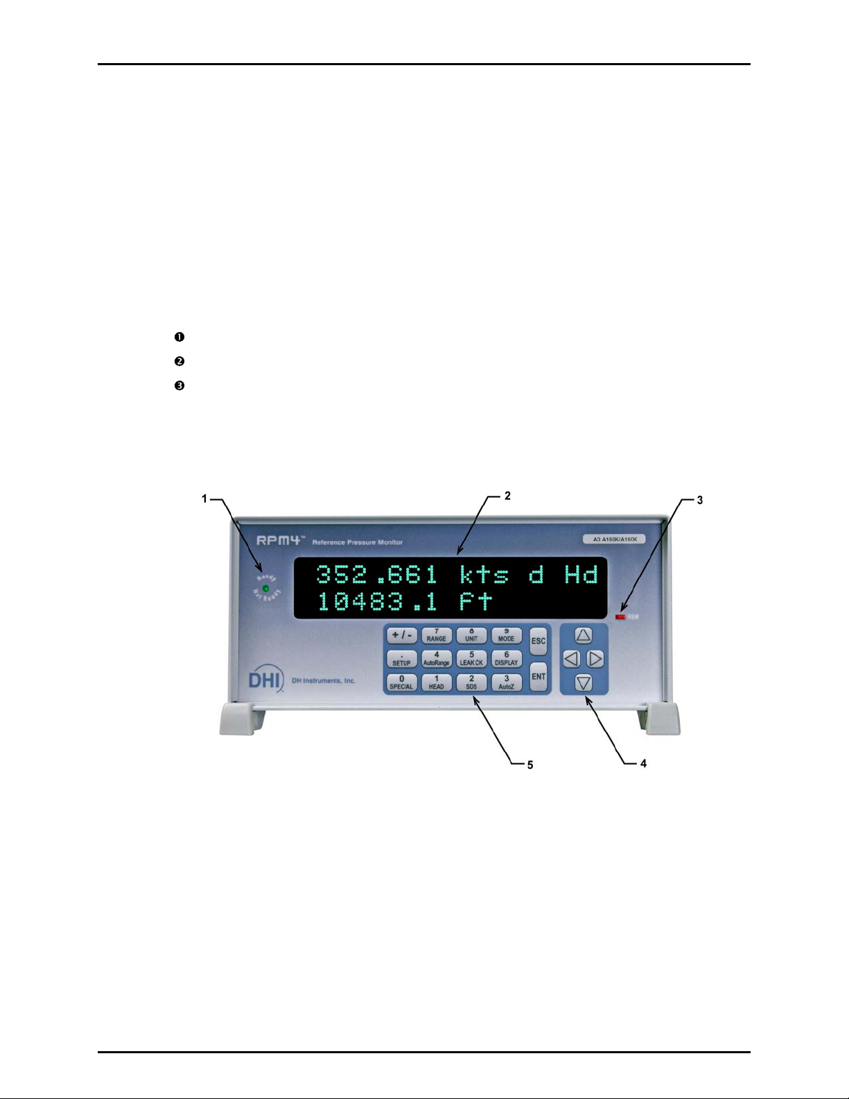
2.3.2.1 FRONT PANEL
1. Ready/not ready indicator
2. Display
3. Remote activity indicator
Figure 1. Front panel
4. Cursor control keys
5. Multi-function keypad
© 2005-2007 DH Instruments, a Fluke Company Page 6
Page 17

2. INSTALLATION
2.3.2.2 REAR PANEL
1. 12VDC power supply
connection
2. Remote [ENT] connector
3. IEEE-488 connector
4. COM2 connector
5. COM1 connector
6. Power switch
7. Fuse
2.3.3 POWER CONNECTION
2.3.3.1 85 TO 264 VAC, 50/60 HZ VAC POWER
Check that the RPM4-AD power switch is OFF.
Connect the supplied power cable to the rear panel power module.
Connect the other end of the power cable to an electrical supply of 85 to 264 VAC,
50/60 Hz.
2.3.3.2 BATTERY PACK
8. Electrical power connector
(IEC-320-C13)
9. Fan
10. Product label (bottom of case)
11. TEST (Ps), low Q-RPT
12. TEST (Pt), high Q-RPT
13. ATM port
14. VENT port
Figure 2. Rear panel
Charge the battery pack fully (see Section 3.2.9).
Connect the RPM4-AD 12VDC power connection on the rear panel of the
RPM4-AD to the 12 VDC power connection on the battery/charge pack using
the cable supplied with the pack.
See Section 3.2.9 for additional information on battery/charger pack
operation and maintenance.
Page 7 © 2005-2007 DH Instruments, a Fluke Company
Page 18

RPM4-AD™ OPERATION AND MAINTENANCE MANUAL
2.3.4 REMOTE [ENT] CONNECTION (FOOTSWITCH OR OTHER SWITCH)
Connect the optional remote ENTER footswitch, if available or a user supplied switch fitted to
the optional cable (see Section 7.1). Connect the cable to the RPM4-AD rear panel
connection labeled REMOTE ENTER. Closing the switch is equivalent to pressing the [ENT]
key on the front panel (see Section 3.1.3).
2.3.5 CONNECTING TO MEASURE PRESSURE (PS AND PT PORTS)
Using a pressure connecting hose or tube of appropriate pressure rating, connect the device
or system to be tested to the RPM4-AD TEST (Pt) and/or TEST (Ps) ports.
The RPM4-AD TEST (Pt) and TEST (Ps) connections are AN4 (1/4 in.) male.
See Table 3 for instructions on how to connect to the RPM4-AD TEST ports depending on
what is to be measured. See Section 5.6 for schematics of RPM4-AD TEST ports
and internal valve configurations. Typically, when testing an air data device, the air data
device Ps port is connected to the RPM4-AD Ps port and the air data device Pt port is
connected to the RPM4-AD Pt port.
, Q-RPTs
Table 3. Making pressure connections to RPM4-AD
MEASUREMENT
Airspeed at varying
altitude (true Ps
and Pt differential
operation)
Altitude only, best
uncertainty
and
absolute pressure
Airspeed at ground
altitude only
(A160K/A160)
and
gauge pressure
Gauge pressure
or
negative gauge
pressure
RPM4-AD A160K/A160K RPM4-AD A350K/A160K TYPE OF
TEST(Pt) TEST(Ps) VENT TEST(Pt) TEST(Ps) VENT
Connect to
DUT Pt
port
Not used.
May be
connected
to DUT Pt
port
Connect to
DUT Pt
port
Connect to
DUT (+) or
gauge port
Connect
to DUT Ps
or altitude
port
Connect
to DUT
Ps,
altitude or
abs port
Not used.
May be
connected
to DUT or
Ps port
Not used Connect
Not used Connect to
Not used Not used.
Not used.
May be
connected
to DUT or
Ps port
to DUT (-)
port
(optional)
DUT Pt
port
May be
connected
to DUT Pt
port
Connect to
DUT Pt
port
Connect to
DUT (+)or
gauge port
to measure
with Hi
Q-RPT
Connect to
DUT Ps or
altitude port
Connect to
DUT Ps,
altitude or
abs port
Not used. May
be connected
to DUT or Ps
port
Connect to
DUT (+)or
gauge port to
measure with
Lo Q-RPT
Not used
Not used
Not used
Connect to
DUT (-)
port
(optional)
RPM4-AD includes the SDS Self Defense System on both of its Q-RPTs. SDS, operated
properly, allows a the Q-RPT TEST port to be left connected to a pressure up to
10 MPa (1 500 psi) without damage to the Q-RPT. Do NOT attempt to use SDS in this
manner without first becoming thoroughly familiar with its operation and limitations (see
Sections 3.2.8, 3.3.8, 3.5.4).
© 2005-2007 DH Instruments, a Fluke Company Page 8
Page 19

2. INSTALLATION
Using the RPM4-AD connected to a system with liquid contaminants without taking
proper precautions to purge the system and test line may cause contamination of the
RPM4-AD that will require non-warranty service.
2.3.6 THE VENT AND ATM PORTS
The RPM4-AD Hi Q-RPT module has a VENT port. The VENT port is connected to the Q-RPT
Self Defense System (SDS) Q-RPT vent valves. The VENT port should always be left completely
unobstructed and open to ambient atmospheric pressure.
RPM4-AD Lo Q-RPT module has an ATM port. The ATM port is connected to the RPM-AD
internal barometer. The VENT port should always be left completely unobstructed and open to
ambient atmospheric pressure. When operating RPM4-AD A160K/A160K in parallel gauge
pressure mode to measure airspeed, the vent port may be connected to the DUT Ps or
altitude port to assure that the RPM4 and the DUT are at the same altitude setting. In this
case, altitude must remain between -700 and 3000 m (110 to 70 kPa abs).
See Section 5.6 for schematics of RPM4-AD TEST and VENT ports, Q-RPT and internal
valve configurations.
NEVER plug, obstruct or connect a supply pressure to an RPM4-AD VENT port. This will
adversely affect GAUGE mode operation and AutoZeroing functions.
2.3.7 CHECK/SET SECURITY LEVEL
RPM4-AD has a security system based on user levels. By default, the security system is set
to “low”, which includes access restriction to internal calibration coefficients, and there is no
password required to change the security level. See Section 3.5.5.5 for information on the
security level system. As part
of the RPM4-AD startup, determine the security level that is
appropriate for the RPM4-AD and set a password if desired.
RPM4-AD is delivered with the security level set to “low” to avoid inadvertent altering of
critical internal settings but with access to changing security levels unrestricted. It is
recommended that the low security level be maintained at all times and password
protection be implemented if control over setting of security levels is desired.
2.3.8 SDS FULL TIME OFF
RPM4-AD includes the SDS Self Defense System on both its TEST ports to shut
them off from a pressure connected to them when they are not in use. If this
function is not desired, SDS can be turned full time off so that in regular
operation, SDS is not present. With SDS full time off, the SDS overpressure
protection is still active.
See Section 3.5.4.2 for instructions on turning SDS full time off if desired.
Page 9 © 2005-2007 DH Instruments, a Fluke Company
Page 20

RPM4-AD™ OPERATION AND MAINTENANCE MANUAL
2.4 POWER-UP AND VERIFICATION
2.4.1 SWITCH POWER ON
Actuate the power switch on the RPM4-AD rear panel (if a 12 VDC power supply is already
connected to the 12 VDC connection, RPM4-AD power is already on). Observe the front panel
display as RPM4-AD initializes, error checks and goes to the MAIN RUN screen (see 3.1.1).
If the RPM4-AD fails to reach
the MAIN RUN screen, service is required. Record the
sequence of operations and displays observed.
SDS is CLOSED at power up and the TEST ports are shut off. This causes <SDS
CLOSED> to be flash periodically in the MAIN RUN screen in place of the measured
pressure value.
2.4.2 CHECK PRESSURE MEASUREMENT OPERATION
2.4.2.1 CHECKING ABSOLUTE MODE PRESSURE MEASUREMENT
Check the RPM4-AD operates properly in absolute mode.
Make sure that the TEST (Ps) and TEST (Pt) ports are vented to atmosphere.
Press the [MODE] function key and select <absolute> mode (see Section 3.3.3).
Use [UNIT] to s
If SDS is
the top line of the display), Press [SDS], <2yes> to OPEN SDS (see Section 3.3.8).
Do NOT OPEN SDS with a pressure higher than the maximum pressure of the
Q-RPT applied to the TEST port. Damage to the Q-RPT may result.
elect a pressure unit of measure (not altitude) (see Section 3.3.2).
CLOSED (<SDS CLOSED> flashes over the display of pressure on
The RPM4-AD should be measuring the current value of atmospheric pressure.
Check that the value agrees with the local value of atmospheric pressure within
measurement tolerances (see Section 1.2.2.1). If RPM4-AD does not agree
within tolerance, it may need to be AutoZeroed (see Section 3.3.9), calibrated
(see Section 5.2) or repaired.
2.4.2.2 CHECKING GAUGE MODE PRESSURE MEASUREMENT
Check the RPM4-AD operates properly in gauge mode.
Make sure that the TEST (Ps) and TEST (Pt) ports are vented to atmosphere.
Press the [MODE] function key and select <gauge> mode. Use [UNIT] to select a
pressure unit of measure (not airspeed) (see Section 3.3.2).
If SDS is
top line of the display), OPEN SDS. Press [SDS], <2yes> to OPEN SDS.
© 2005-2007 DH Instruments, a Fluke Company Page 10
CLOSED (<SDS CLOSED> flashes over the display of pressure on the
Do NOT OPEN SDS with a pressure higher than the maximum pressure of the
Q-RPT applied to the TEST port. Damage to the Q-RPT may result.
Page 21

2. INSTALLATION
The value indicated should be near zero. It is normal for RPM4-AD to indicate a
value other than zero when vented when gauge mode is first entered or the
range is changed. Press [AutoZ]. This runs AutoZ to zero the Q-RPT reading
(see Section 3.3.9.1). Upon return to the MAIN RUN screen, observe that the
indication of measured pressure has zeroed.
If the display fails to zero properly, RPM4-AD may need repair.
2.5 SHORT TERM STORAGE
The following is recommended for short term storage of RPM4:
Remove pressure from the RPM4-AD TEST ports.
Switch power OFF.
Page 11 © 2005-2007 DH Instruments, a Fluke Company
Page 22

RPM4-AD™ OPERATION AND MAINTENANCE MANUAL
N
N
OOTTEES
S
© 2005-2007 DH Instruments, a Fluke Company Page 12
Page 23

3. OPERATION
33..
O
PPEERRAATTIIOON
O
N
3.1 USER INTERFACE
RPM4-AD is designed to offer a balance between simple, straight forward operation and the availability of
a wide variety of advanced functions with a high level of operator discretion. The local operator interface
is through a 2 x 20 character alphanumeric display, a function/data keypad, a cursor control pad and a
Ready/Not Ready indicator.
Remote communications are by RS232 (COM1) and IEEE-488. See Section 4 for information on remote
communication.
3.1.1 MAIN RUN SCREEN
The RPM4-AD MAIN RUN screen is its home display that is reached on power-up and from
which other functions and menus are accessed. It is the very top level of all menu structures.
The MAIN RUN screen is where RPM4-AD is left in normal operation. It displays the current
measured pressure, altitude and/or airspeed as well as a variety of additional information if
desired.
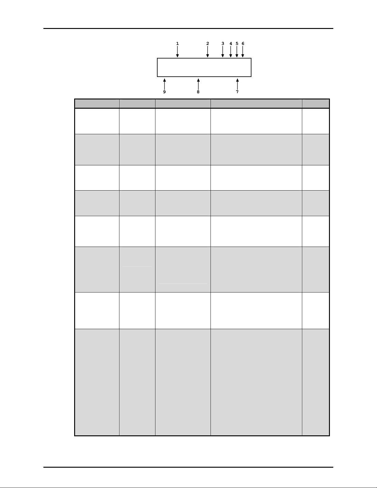
Figure 3 and its legend summarize the RPM4-AD MAIN RUN screen fields and their functions.
RPM4-AD has a screen saver function which causes the display to dim if no key is pressed for
10 minutes. Pressing a key restores full power to the display. The screen saver time can be
changed or screen saving can be completely suppressed (see Section 3.5.5.1).
Page 13 © 2005-2007 DH Instruments, a Fluke Company
Page 24
RPM4-AD™ OPERATION AND MAINTENANCE MANUAL
PRESSURE1UNITM hzRR
DDISPLAYFUNCION
DISPLAY FIELD NAME PURPOSE CONTENTS SECTION
1. PRESSURE1 Measured
pressure,
altitude or
airspeed
2. UNIT Unit of
measure
Displays value
measured by the
active Q-RPT(s)
Identifies unit of
measure in which
Numerical pressure value and sign.
3.2.8
Intermittently flashes <SDS CLOSED>
when the Q-RPT is shut off from the
TEST port by SDS.
Unit of measure abbreviation 3.3.2
pressure or pressure
derived values are
displayed
3. M Measurement
mode
4. h Head
indicator
Identifies measurement
mode of displayed
pressure or air data
value
Indicates whether a
fluid head correction
<a> absolute
<g> gauge or negative gauge
<d> differential
<h> the fluid head is not zero
<blank> fluid head is zero
3.3.3
3.3.7
is applied to
PRESSURE1
5. z AutoZero
indicator
Indicates whether the
AutoZero function is
<z> AutoZ is ON
<blank> AutoZ is OFF
3.5.1
ON or OFF for the
active Q-RPT and
measurement mode
6. RR Active
Q-RPT
indicator
Indicates the active
Q-RPT in the RPM4.
The active Q-RPT
measurement is
displayed on the RPM4
top line.
<Hi> Hi Q-RPT
<Lo> Lo Q-RPT
<HL> Hi and Lo Q-RPTs together in
parallel measurement mode
(A160K/A160K only)
<Hd> Hi and Lo Q-RPTs together in
3.2.1
differential measurement mode
8. DISPLAY
FUNCTION
Information
specific to the
DISPLAY
mode
Pressure indication
depending on current
RPM4-AD DISPLAY
function. Leading
Numerical pressure value
and sign.
3.3.6
character identifies the
value
9. D Pressure
information
indicator
Pressure information
indicator depending on
current RPM4-AD
DISPLAY function.
<σ> Display mode is AVERAGE
and value is standard deviation
<R> Display mode is RATE and
value is pressure or air data
3.3.6
unit rate of change per second
</s> or per minute </m>
<H> Display mode is HI/LO and
values high (left), low (right)
<D> Display mode is DEVIATION
and value is difference from
current target
None Display mode is RPT and value is
measurement of inactive RPT
(<Lo> or <Hi> to right)
<F> Display mode is FREEZE and
value is last captured reading
Blank, no character Current display
mode is CLEAN
Figure 3. MAIN RUN screen display fields
© 2005-2007 DH Instruments, a Fluke Company Page 14
Page 25
3. OPERATION
3.1.2 FUNCTION / DATA KEYPAD LAYOUT AND PROTOCOL
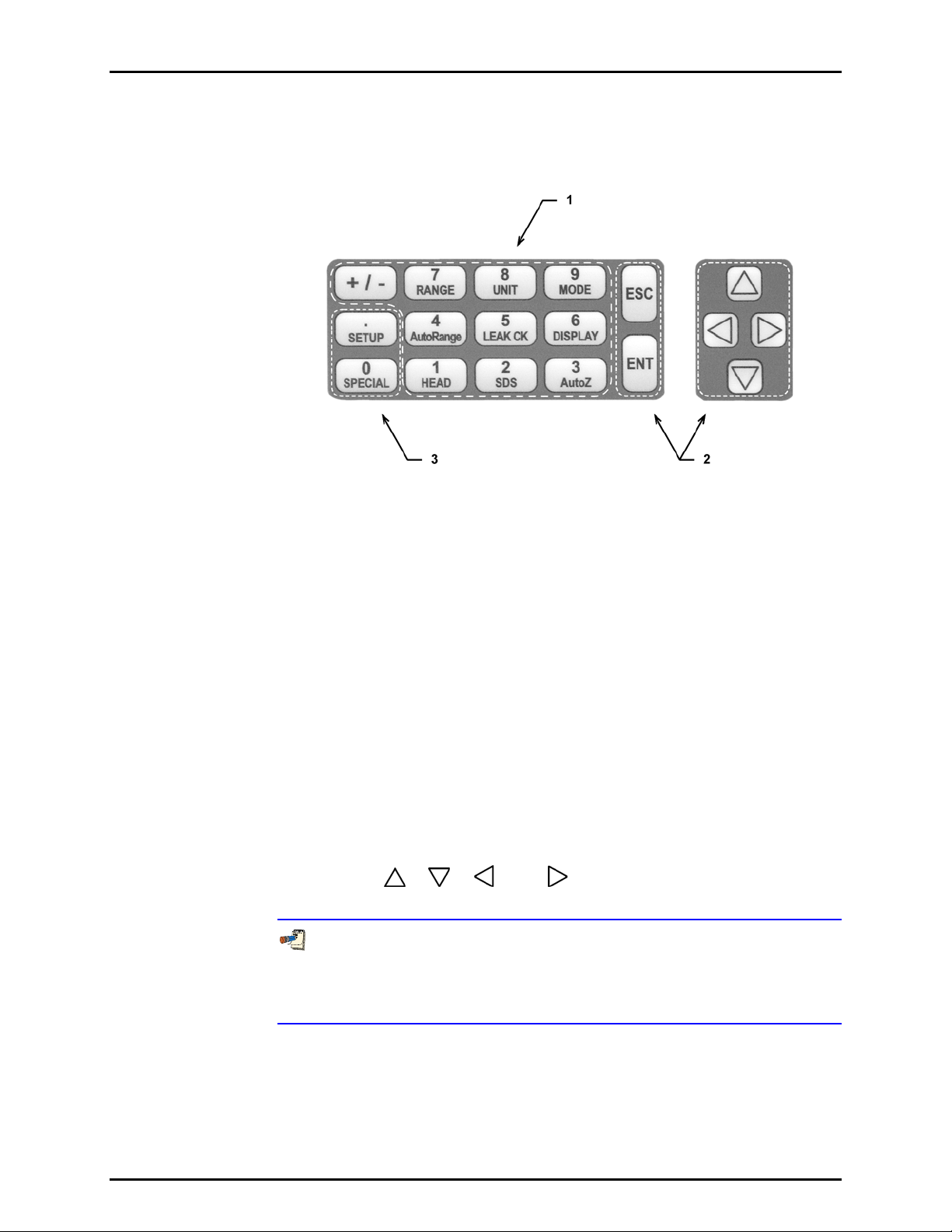
The RPM4-AD has a function/data keypad for local operator access to direct
functions, function menus and for data entry.
1. The Function/Data keys allow very commonly
used functions to be accessed directly by a
single keystroke when pressed from the
MAIN RUN screen (see Section 3.1.1).
The name of the function is on
half of the key. These keys enter numerical
values when editing.
2. The Editing and Execution keys are for
starting and suspending command execution,
cursor control in menus and editing entries.
the bottom
3. The Menu/Data keys provide access to
function menus when pressed from the
MAIN RUN screen. The menu name is on
the bottom half of the key. The SETUP
menu is for more frequently used functions
(see Section 3.4). The SPECIAL menu is for
functions that are not generally
of day to day operation (see Section 3.5).
These key
s enter numerical values when editing.
used as a part
Figure 4. Keypad layout
Pressing the [ENT] key generally causes execution or forward movement in the
menu tree.
Pressing the [ESC] key moves back in the menu tree and/or causes execution to
cease or suspend. Pressing [ESC] repeatedly eventually returns to the MAIN RUN
screen and, from there, allows momentary viewing of the RPM4-AD introduction
screen.
Pressing the [+/-] key changes a numerical sign when editing. It also toggles
through multiple screens when available and, from some run screens, is a
shortcut to a momentary display of active RANGE.
Pressing the [
], [ ], [ ] and [ ] keys allows up, down, reverse and
forward cursor movement when editing data entry or moving in menus.
Some screens go beyond the two lines provided by the display. This is
indicated by a flashing arrow in the second line of the display. Press the
cursor control keys to move the cursor to access the lines that are not
visible or directly enter the number of the hidden menu choice if you know it.
Page 15 © 2005-2007 DH Instruments, a Fluke Company
Page 26
RPM4-AD™ OPERATION AND MAINTENANCE MANUAL
3.1.3 REMOTE [ENT] (ENTER) FOOTSWITCH
The optional remote ENTER function is a switch that duplicates the function of the front panel
[ENT] key. The remote ENTER function is serviced by a connector on the RPM4-AD rear
panel. An optional footswitch is available to activate remote entry hands free or a different
switch may be used. See Section 7.1 for information on remote ENTER switch wiring.
3.1.4 SOUNDS
RPM4-AD is equipped with a variable frequency tone device to provide audible feedback and
alarms. The beeper is used for the following indications.
Valid key press
Brief beep. Choice between three frequencies or NO
sound is available (see Section 3.5.5.2).
alid key press
Inv
Leak check completed
Upper or low
Pmax! (ov
er limit exceeded
erpressure limit)
Descending two tone “blurp”
Three two second beeps (see Section 3.3.5).
Intermittent one second beeps (see Section 3.4.4).
Eight second high frequency beep (see Section 3.4.4.1).
exceeded
Possible disconnect betw
een
Rapid beeps for 8 seconds (3.2.5).
the Hi and Lo Q-RPTs in
parallel measurement mode
3.2 GENERAL OPERATING PRINCIPLES
3.2.1 Q-RPTS AND Q-RPT SELECTION
RPM4-AD has two Q-RPTs. In RPM4-AD A160K/A160K the two Q-RPTs have of the same
range of 160 kPa absolute (23 psi). In RPM4-AD A350K/A160K the Hi Q-RPT has a range of
350 kPa (51 psi) and the Lo Q-RPT has a range of 160 kPa (23 psi). Position indication of
the currently active Q-RPT is continuously displayed in the upper right hand corner of the
MAIN RUN screen and most other screens. See Section 5.6 for a schematic of the RPM4-AD
pneumatic system and Q-RPTs.
in an RPM4-AD.
See Table 4 for position designation protocol for the Q-RPTs
Table 4. Position designators of Q-RPTs in an RPM4-AD system
Q-RPT POSITION DISPLAY SYMBOL*
A160K/A160K: A160K Q-RPT installed in
HIGH RPT (Pt) position.
A350K/A160K: A350K Q-RPT installed in
HIGH RPT (Pt) position.
Hi Q-RPT when used in differential
measurement mode (Hi – Lo)
A160K/A160K: A160K Q-RPT installed in
LOW RPT (Ps) position.
A350K/A160K: A160K Q-RPT installed in
LOW RPT (Ps) position.
Both Q-RPTs being used simultaneously
in parallel measurement mode (RPM4AD A160K/A160K only)
* The display symbol is included in the upper, right hand corner of most RPM4-
AD menu displays as a convenient indicator of the active Q-RPT.
© 2005-2007 DH Instruments, a Fluke Company Page 16
<Hi>
<Hd>
<Lo>
<HL>
Page 27
3. OPERATION
AN RPM4-AD Q-RPT is identified by a range screen identifying the Q-RPT, its current unit of measure
and its full scale pressure in gauge and absolute measurement modes or in an air data unit. The
Q-RPT screen is:
1. Q-RPT designator.
2. Q-RPT position designator.
3. Current pressure unit of measure.
4. Full scale pressure in current unit of measure in gauge (<g>) and/or absolute
(<a>) measurement mode.
Active A160K Hi
inHg 17.7g/47.2a
The Q-RPTs available on an RPM4-AD and short cuts to specific air data measurement
modes are accessed using [RANGE].
Most settings made when an RPM4-AD Q-RPT is active, such as unit of measure,
measurement mode, display resolution, and stability setting are specific to the Q-RPT.
Generally, settings selected while one Q-RPT is active apply to that Q-RPT and not to the
other Q-RPT. The Q-RPT specific settings are stored with the Q-RPT and recalled whenever
the Q-RPT is made active. See Table 5 for a listing of RPM4-AD settings and to what level of
RPM4-AD operation they are specific.
Table 5. Settings and what they are specific to
(range, measurement mode, Q-RPT, system)
SETTING PURPOSE SPECIFIC TO SECTION
[Unit]
[Mode]
[Display]
[Head]
[SDS]
[AutoZ]
Resolution Set pressure display resolution Q-RPT 3.4.2
Stability Set Ready/Not Ready stability test. Q-RPT 3.4.3
Upper Limit Set upper and lower pressure limit alarm Q-RPT and measurement mode 3.4.4
AutoZ AutoZ ON/OFF, set and view values Q-RPT and measurement mode 3.5.1
Screen Saver,
Sound, Time,
ID, Level
ReadRate Automated read rate adjustment ON/OFF System 3.5.7.2
Cal Q-RPT and barometer calibration coefficient
Set pressure unit of measure Q-RPT and measurement mode 3.3.2
Set pressure measurement mode (absolute,
gauge, negative gauge)
Set bottom line display function System 3.3.6
Set fluid head correction height, fluid, unit of
measure
Open and close SDS Q-RPT 3.3.8
Run AutoZ Q-RPT and measurement mode 3.3.9
Set system user preferences System 3.5.5
and date viewing and editing
Q-RPT 3.3.3
System 3.3.7
Q-RPT or barometer 3.5.7.5
3.2.2 GAUGE AND NEGATIVE GAUGE MEASUREMENT, DYNAMIC COMPENSATION FOR ATMOSPHERIC PRESSURE
RPM4-AD Q-RPTs are intrinsically absolute but they are also used for gauge and negative gauge
measurement modes (see Section 3.3.3,
achieved by subtracting the value of atmospheric pressure, P
reading using AutoZ (see Section 3.2.2). The AutoZ routine that measures P
PRINCIPLE). Gauge measurement modes are
, from the Q-RPT’s absolute
offset,G
, is run by
offset,G
pressing [AutoZ] whenever RPM4-AD is in the vented condition. This assures the continuous
Page 17 © 2005-2007 DH Instruments, a Fluke Company
Page 28

RPM4-AD™ OPERATION AND MAINTENANCE MANUAL
updating of the P
measured absolute pressure, P
value corresponding to atmospheric pressure. Gauge pressure is the
offset,G
, minus the atmospheric offset.
u
P
gauge
= Pu - P
offset,G
However, atmospheric pressure may change between opportunities to run AutoZ and update
the value of P
, for example when running an extended test without venting. RPM4-AD
offset,G
uses dynamic compensation for atmospheric pressure to correct for changes in
atmospheric pressure between opportunities to run AutoZ and update P
runs, and P
is determined, the reading of RPM4’s on board barometer, P
offset,G
recorded. Later, when no longer vented, the change in atmospheric pressure, ΔP
P
barometer reading at the time of AutoZ execution, P
Dynamic compensation for atmospheric pressure uses ΔP
was updated, is the difference between the current barometer reading, P
offset,G
:
atm,0
ΔP
= P
atm
atm
- P
atm,0
to correct the value of P
atm
. When AutoZ
offset,G
atm,0
, is also
, since
atm
, and the
atm
offset,G
,
thus always compensating real time for changes in atmospheric pressure:
P
gauge
= Pu - P
offset,G
- ΔP
atm
Gauge pressure measurement on an Axxx (absolute) Q-RPT allows instantaneous switching
between gauge and absolute measurements modes. The additional uncertainty in gauge
pressure mode due to the dynamic compensation for atmospheric pressure technique is a
function of the resolution and short term stability of the on-board barometer, not its absolute
measurement uncertainty. This additional uncertainty is ± 1 Pa (0.00015 psi).
In RPM4-AD A160K/A160K the two A160K Q-RPTs are used in parallel measurement
mode in gauge mode to reduce measurement uncertainty (see Section 3.2.5). Gauge
mode can be used to measure airspeed in parallel measurement mode. This provides
airspeed measurement but only at ground altitude corresponding to the current value of
atmospheric pressure (see Section 3.2.3.1).
3.2.3 ALTITUDE AND AIRSPEED MEASUREMENT
RPM4-AD is designed to support the measurement of altitude and airspeed with minimal
uncertainty. See Section 3.2.3.1 for information on altitude and airspeed measurement
RPM4-AD A160K/A160K (rotary wing) and Section 3.2.3.2 for information on RPM4-AD
A350K/A160K (fixed wing).
3.2.3.1 RPM4-AD A160K/A160K (ROTARY WING)
RPM4-AD A160K/A160K has two 160 kPa absolute Q-RPTs, one in the HIGH
RPT (Pt) position and one in the LOW RPT (Ps) position.
Air data measurements can be made in three different conditions.
The two Q-RPTs measuring two absolute pressures (Ps and Pt) separately:
airspeed at varying altitude
In differential mode, the two Q-RPTs are separated internally. One is connected
to the TEST (Ps) port and the other is connected to the TEST (Pt) port (see
Section 3.2.6).
RPM4
ports. The absolute pressure measured on the TEST (Ps) port is converted to
altitude. The difference between the TEST (Pt) and TEST (Ps) pressure
(Pt - Ps) is converted to airspeed (see Section 7.2.3). If a true airspeed unit of
measure has been selected, altitude and entered
the airspeed calculation.
measures the absolute pressures applied to the TEST (Ps) and TEST (Pt)
temperature are also used in
with
© 2005-2007 DH Instruments, a Fluke Company Page 18
Page 29

3. OPERATION
To measure airspeed and altitude using this mode, use [RANGE] (see Section
3.3.1.1) t
o select the <Hi> Q-RPT or the <airspeed & altitude> shortcut. If the
shortcut is not used, once the Q-RPT has been selected, use [MODE] (see
Section 3.3.3) to set absolute and differential measurement mode and [UNIT]
(see Section 3.3.2) to set the desired airspeed unit. Use [DISPLAY], <4RP
T> to
change the altitude unit if desired.
The two Q-RPTs measuring absolute pressure in parallel: Altitude only,
with lowest uncertainty
In parallel mode (//m
TM
), the two Q-RPTs are connected together internally, the
TEST (Ps) port is opened and the TEST (Pt) port is closed using the SDS
valves.
RPM4 measures the absolute pressure applied to the TEST (Ps) port with both
Q-RPTs and averages the two (see Section 3.2.5). The absolute pressure is
converted to altitude (see Section 7.2.2).
To measure altitude using this mode, use [RANGE] (see Section 3.3.1) t
o select
the <HL> Q-RPT or the <altitude, parallel> shortcut. If the shortcut is not used,
once the Q-RPT has been selected, use [MODE] (see Section 3.3.3) to set
absolute measurement mode and [UNIT] (see Section 3.3.2) to set the desired
altitude unit.
The tw
o Q-RPTs measuring gauge pressure in parallel: Airspeed at ground
altitude only
In parallel mode, the two Q-RPTs are connected together internally, the TEST
(Pt) port is opened and the TEST (Ps) port is closed using the SDS valves.
RPM4 measures the gauge pressure applied to the TEST (Pt) port with both Q-
RPTs and averages the two (see Section 3.2.5). Since the gauge pressure is the
difference
from atmospheric pressure, it directly provides the differential pressure
used to calculate airspeed. The value of static pressure, Ps, is the current value
of atmospheric pressure. The gauge pressure is converted to airspeed (see
Section 7.2.3). The value of ground altitude corresponding to ambient
atmospheric pressure can also be displayed.
If a true airspeed unit of measure
has been selected, altitude and entered temperature are also used in the
airspeed calculation.
To measure airspeed using this mode, use [RANGE] (see Section 3.3.1.1) to
the <HL> Q-RPT or the <airspeed, parallel> shortcut. If the shortcut is
select
not used, once the Q-RPT has been selected, use [MODE] (see Section 3.3.3) to
gauge measurement mode and [UNIT] (see Section 3.3.2) to set the desired
set
airspeed unit.
3.2.3.2 RPM4-AD A350K/A160K (FIXED WING)
RPM4-AD A350K/A160K has two Q-RPTs. A 350 kPa absolute Q-RPTs is in the
HIGH RPT (Pt) position and a 160 kPa absolute is in the LOW RPT (Ps) position.
Air data measurements are normally made in the following conditions:
The two Q-RPTs are separated internally. One is connected to the TEST (Ps)
port and the other is connected to the TEST (Pt) port.
RPM4 measures the absolute pressures applied to the TEST (Ps) and TEST (Pt)
ports. The absolute pressure measured on the TEST (Ps) port is converted to
altitude. The difference between the TEST (Pt) and TEST (Ps) pressure (Pt –
Ps) is converted to airspeed (see Section 7.2.3). If a true airspeed unit of
measure has been selected, altitude and entered
the airspeed calculation.
Page 19 © 2005-2007 DH Instruments, a Fluke Company
temperature are also used in
Page 30

RPM4-AD™ OPERATION AND MAINTENANCE MANUAL
To measure airspeed and altitude using this mode, use [RANGE] (see Section
3.3.1.2) t
o select the <Hi> Q-RPT or the <airspeed & altitude> shortcut. If the
shortcut is not used, once the Q-RPT has been selected, use [MODE] (see
Section 3.3.3) to set absolute and differential measurement mode and [UNIT]
(see Section 3.3.2) to set the desired airspeed unit. Use [DISPLAY], <4RP
change the altitude unit if desired (see Section 3.3.6.4).
3.2.4 PRESSURE READY/NOT READY
There is a Ready/Not Ready indication LED on the RPM4-AD front panel. This indication is
intended to provide the user with an objective indication of when a stable pressure has been
achieved. Ready is indicated when the current stability (rate of change) of pressure is less
than the stability limit. The user can set the stability limit (see Section 3.4.3). The ready
indication
valid reading can be made.
The Ready/Not Ready LED indications are:
is often used when comparing the RPM4-AD and a test device to indicate when a
The Ready/Not Ready indication always applies to the active Q-RPT, whose pressure
measurement is displayed on the top line of the RPM4-AD display.
T> to
<Green > Pressure Ready The pressure stability is within the stability limit.
<Red> Pressure Not Ready The pressure stability is NOT within the stability limit.
In differential measurement mode (see Section 3.2.6), the LED Ready/Not Ready
indication applies to the differential pressures.
In parallel measurement mode (see Section 3.2.5), the LED Ready/Not Ready indication
applies to the average pressure read by the <HL> Q-RPT
.
The Ready/Not Ready LED indications are:
<Green > Pressure Ready The pressure stability is within the stability limit.
<Red> Pressure Not Ready The pressure stability is NOT within the stability limit.
The default stability limit criteria for the Ready/Not Ready determination is:
Absolute measurement mode: ± 0.001875% of absolute mode span
Gauge measurement mode: ± 0.005% of gauge mode span
3.2.5 PARALLEL MEASUREMENT MODE (//MTM) (RPM4-AD A160K/A160K ONLY)
RPM4-AD A160K/A160K can be set to operate in parallel measurement mode. Parallel
measurement mode is used to measure altitude with the lowest uncertainty (see Section 3.2.3.1).
Parallel measurement mode is intended to improve measurement reliability and reduce measurement
uncertainty by using the
measurements of two Q-RPTs together. In parallel measurement
mode, the measured pressure is the average of the readings of the two Q-RPTs.
Parallel measurement mode is considered a Q-RPT designated <HL> (combination of Hi and
Lo). The HL Q-RPT can be selected using the [RANGE] (see Section 3.3.1.1) key and
operated
with all the features of a Hi or Lo Q-RPT.
In parallel measurement mode the active TEST port depends upon the measurement mode. In
absolute measurement mode the TEST(Ps) port is active and the TEST(Pt) port is shutoff. In
gauge measurement mode the TEST(Pt) port is active and the TEST(Ps) port is shutoff.
© 2005-2007 DH Instruments, a Fluke Company Page 20
Page 31

3. OPERATION
3.2.6 DIFFERENTIAL MEASUREMENT MODE
RPM4-AD can be set to operate in differential measurement mode. Differential measurement
mode is used to measure airspeed and varying altitude (see Section 3.2.3).
In differential measurement mode, the measured pressure is the
measurements of the two Q-RPTs (Hi – Lo, Pt – Ps).
To set up differential measurement mode, use [RANGE] (see Section 3.3.1) to select the
<Hi
> Q-RPT or the <airspeed & altitude> shortcut. If the shortcut is not used, once the
Q-RPT has been selected, use [MODE] (see Section 3.3.3) to set absolute and differential
measurement mode.
difference between
3.2.7 AUTOZERO FUNCTION
RPM-AD includes an AutoZero function. This function is used to rezero the Q-RPT readings
in gauge and differential modes and to offset the Q-RPT relative to a reference standard in
absolute mode.
See Section 3.5.1 for complete information on the AutoZ function.
In gauge measurement mode, AutoZ should be run when the mode
time RPM4-AD is vented (zero gauge pressure applied) (see Section 3.3.9.1).
In differential measurement mode,
selected and any time zero differential is set or the line pressure (altitude) is changed (see
Section 3.3.9.3).
In absolute measurement mode, it is recommended that AutoZ be run e
when RPM4-AD has been exposed to temperature changes exceeding 15 ºC (36 ºF) (see
Section 3.3.9.2).
the AutoZ function should be run when the mode is first
is first selected and any
very 30 days or
3.2.8 SDS SELF DEFENSE SYSTEM
The RPM4-AD Q-RPTs modules are equipped with the SDS self defense system. The SDS
system includes hardware and embedded software to isolate Q-RPTs from overpressure.
When SDS is CLOSED for a Q-RPT module, the Q-RPT is isolated from the module’s TEST port
and opened to the module’s VENT port (See Section 5.6, Figure 8, Figure 9).
SDS can be OPENED and CLOSED from the front panel using [SDS]. SDS can also be
controlled using functions under [SPECIAL], <
allows SDS on both Q-RPTs and TEST ports, whether active or inactive, to be opened and
closed directly (see Section 3.5.4.1). The SDS “full time on/off” func
opened permanently so the RPM4-AD can be operated as if SDS were not installed (see
Section 3.5.4.2).
SDS is normally used to isolate an RPM4-AD
sometimes be subjected to pressures higher than the Q-RPT’s maximum pressure. When
configuring a multi-range system, this can eliminate the need for external valving or
connecting and disconnecting RPM4s. For example, two Q-RPTs of different ranges might
be connected to a single calibration system. When the Hi Q-RPT is in use, SDS is closed on
the Lo Q-RPT to protect it from overpressure. When used in this manner, SDS should be
CLOSED prior to applying pressure. Automatic SDS closing in response to overpressure
should only be used in an emergency overpressure situation.
SDS also attempts to protect Q-RPTs from accidental overpressure. Whenever RPM4-AD is
powered ON it continuously monitors the pressure read by its Q-RPT(s). If the pressure
reaches the maximum pressure limit for a Q-RPT, SDS CLOSES to isolate the Q-RPT from
the TEST port and vent it to atmosphere. This is not a fail safe overpressure system. It does
not protect against very rapid overpressure or pressure exceeding 10 MPa (1 500 psi).
4SDS>. The SDS “temp open/close” function
tion allows SDS to be
Q-RPT from a test system which may
See Section 5.6 for schematics of the RPM4-AD
indication of internal valve states for SDS open and closed.
Page 21 © 2005-2007 DH Instruments, a Fluke Company
Q-RPTs and pneumatic system and
Page 32

RPM4-AD™ OPERATION AND MAINTENANCE MANUAL
The maximum pressure that should be applied to an RPM4-AD TEST port when SDS is
CLOSED is 10 MPa (1 500 psi).
Though the SDS self defense system includes features to automatically protect Q-RPTs
against accidental overpressure, SDS should NOT be considered a fail-safe overpressure
protection system. SDS cannot guarantee that overpressure damage will NOT occur.
Conventional measures for overpressure protection should also always be used. Damage
to Q-RPTs due to overpressure is NOT covered by the RPM4-AD product warranty even
when SDS is present and ON.
3.2.9 USE OF THE 12VDC BATTERY/CHARGER PACK
An optional 12VDC battery/charger pack is available to supply power to RPM4-AD’s 12VDC
power connection.
The battery/charger pack combines the battery and the battery charger.
To Charge the Battery
The battery may be charged while the battery/charge pack is connected to the RPM4-AD.
To charge the battery, connect the battery/charger pack to a 100 to 240 V, 50/60 Hz power
supply using the supplied power cable and turn on the charger power switch. The green
CHARGE indicator light goes on to indicate that battery charging is in progress. Allow 14 to
16 hours for the battery to charge fully. When the battery is fully charged, the CHARGE
indicator light flashes.
When the battery charger power switch is in the ON, the battery is connected to the charger,
not the 12VDC output. When the battery charger switch is in the OFF position, the CHARGE
indicator light goes off, and 12VDC is supplied on the 12VDC connection.
To Use the Battery/Charger Pack to Supply RPM4
After charging the battery, connect the 12VDC connection of the battery/charger pack to the
12VDC connection on the RPM4-AD rear panel.
Turn the battery/charger pack power switch to OFF (when AC power is connected to the
battery/charger pack, the power switch must be OFF for 12VDC power to be output).
When RPM4-AD is connected to both a 12 VDC source and an AC source, if the RPM4-AD
power switch is OFF, the 12VDC source supplies the RPM4; if the RPM4-AD power switch is
ON, the 12 VDC source is disconnected and the AC source supplies the RPM4-AD.
To Check the Battery Charge Level
To check the current charge level of the battery, press the toggle switch on the
battery/charger pack front panel. Observe the BATTERY CHECK indicator lights. All three
lights are lit when battery is fully charged. If no light or one light is on, the battery should be
recharged.
© 2005-2007 DH Instruments, a Fluke Company Page 22
Page 33

3. OPERATION
Figure 5. Battery pack/charger
3.2.10 USING RPM4-AD WITH A PPC3 CONTROLLER/CALIBRATOR
Certain RPM4 models can be used as an external measurement device for a PPC3 pressure
controller/calibration.
RPM4-AD cannot be used as a PPC3 external measurement device.
3.2.11 DIRECT FUNCTION KEYS SUMMARY
Table 6 provides a brief summary of direct function key operation. It may be useful to
keep a copy of this summary near the RPM4-AD, especially when first becoming
acquainted with its operation.
Local operation of RPM4-AD is through the front panel keypad. To minimize multi-layered
menu structures, the keypad numerical keys also provide direct access to the most
commonly used functions. The function accessed is labeled on the bottom half of the key.
Direct function keys are active whenever RPM4-AD is in its MAIN RUN screen. Table 6
summarizes the operation of the direct function keys.
Page 23 © 2005-2007 DH Instruments, a Fluke Company
Page 34

RPM4-AD™ OPERATION AND MAINTENANCE MANUAL
Table 6. Summary of RPM4-AD function key operation
DIRECT FUNCTION KEYS ARE ACTIVE FROM THE MAIN RUN SCREEN
See corresponding manual sections for full detail.
Adjust height of fluid head
correction. Set to zero to defeat
correction.
SDS controls the connection of the
Q-RPT to the TEST(Pt) and/or
TEST(Ps) port. Closes any open
SDS. Opens SDS of active QRPT if closed.
Run the AutoZ function to
AutoZero the active Q-RPT and
measurement mode.
View and toggle through active QRPT and setup shortcuts. [ENT]
on a Q-RPT or shortcut activates it.
Select pressure unit of measure for
the active range. Choice of units
available in this menu depends on
current measurement mode.
Choice of units can be customized.
Select the pressure measurement
mode for the active Q-RPT
(absolute, gauge, negative gauge,
differential).
This function is not used in RPM4AD models.
Run automated leak checking
routine, also used for average rate
measurements (e.g. ascent,
descent).
Select the display function for the
bottom line of the RPM4-AD
display.
3.3 DIRECT FUNCTION KEYS
3.3.1 [RANGE]
PURPOSE
To view and/or change the active Q-RPT and associated settings. Includes direct shortcuts
to air data measurement modes.
PRINCIPLE
RPM4-AD has two Q-RPTs.
In RPM4 A160K/A160K, the two Q-RPTs may be used in parallel (<HL>) or the Hi Q-RPT
may be used alone (<Hi>) or in true differential mode with the Lo Q-RPT (<Hd>).
Menu of less commonly used internal
functions and settings.
Menu of commonly used setup
features including set display
resolution, set stability limit.
Start or set functions such as Leak
Check and Freeze. ENTER values
when editing.
In RPM4 A350K/A160K, the Hi Q-RPT (<Hi>) or the Lo Q-RPT (<Lo>) may be used
individually. Differential use of the two Q-RPTs is accessed by selecting the Hi Q-RPT
(<Hd>). Parallel mode of the two Q-RPTs is not supported.
The [RANGE] function key is used to specify which Q-RPT (and associated range and settings) is
active.
To streamline RPM4-AD operation, the [RANGE] key also provides simple shortcuts to the
RPM4-AD configurations that support air data measurements.
See Section 4.4.5 for procedures to accomplish the same air data setups as [RANGE]
shortcuts using remote commands.
© 2005-2007 DH Instruments, a Fluke Company Page 24
Page 35

3. OPERATION
OPERATION
Pressing the [RANGE] function key activates the Q-RPT viewing and selecting function.
When the [RANGE] function key is first pressed, the active Q-RPT is displayed. For example:
1. Q-RPT designator.
2. Q-RPT position designator (<Hi>, <Lo>, <HL> for both Q-RPTs in
parallel mode, <Hd> for Hi Q-RPT in differential mode with the Lo Q-RPT).
3. Current unit of measure.
4. Full scale pressure of Q-RPT in current unit of measure in gauge (<g>) and
absolute (<a>) measurement modes for pressure unit of measure or in air
data unit.
Active A160K Hi
kPa 60g/160a
Pressing the [RANGE] key again while in the RANGE functions toggles through displays of
the other available Q-RPTs and shortcuts to air data measurement configurations (see below for
RPM4-AD A160K/A160K and RPM4-AD A350K/A160K [RANGE] key choice details). The [
and [
] keys can also be used to move forwards or backwards through the selections.
To select a Q-RPT or shortcut, press [ENT] when it is displayed.
Pressing [ESC] while in the RANGE function returns to the MAIN RUN screen without
making any change.
Q-RPT specific RPM4-AD operating settings are saved with the Q-RPT when another Q-RPT
is made active (see Section 3.2.1, Table 5). When the Q-RPT is selected again, it has the
same settings as it was left with. The air data measurement shortcuts always
return to the
Q-RPT and measurement mode necessary for the air data measurement. They retain all
other user settings.
]
3.3.1.1 RPM4-AD A160K/A160K (ROTARY WING)
Pressing [RANGE] always displays the active Q-RPT information. Pressing
[RANGE] again toggles through the other Q-RPT choices available and the three
air data shortcuts. There are a total of five [RANGE] displays.
The first time [RANGE] is pressed, the active range is displayed. Pressing
[RANGE] again displays the next range choice. Pressing [ENT] activates the
displayed selection and returns to the main run screen.
The sequence of selections when [RANGE] is pressed is:
FIRST [RANGE] SELECTION: HI Q-RPT
Selects Hi Q-RPT with all previous
settings (measurement mode, unit of
measure, etc) for that Q-RPT.
SECOND [RANGE] SELECTION: HL (PARALLEL MODE) Q-RPT
Selects HL Q-RPT (Hi and Lo Q-RPTs in
parallel ) with all previous settings
(measurement mode, unit of measure,
etc) for that Q-RPT.
Select A160K Hi
kPa 60g/160a
Active A160K HL
kPa 60g/160a
Page 25 © 2005-2007 DH Instruments, a Fluke Company
Page 36

RPM4-AD™ OPERATION AND MAINTENANCE MANUAL
THIRD [RANGE] SELECTION: HI Q-RPT, SHORTCUT TO AIRSPEED AT
VARYING ALTITUDE
Selects Hi Q-RPT in absolute, differential
measurement mode (<Hd>) in which Hi
– Lo Q-RPT differential pressure
(airspeed) is displayed on top line and
Lo Q-RPT absolute pressure (altitude)
on the bottom line. Units of measure are
default or last selected airspeed and
altitude units.
FOURTH [RANGE] SELECTION: HL Q-RPT, SHORTCUT TO ALTITUDE,
BEST UNCERTAINTY
Selects HL Q-RPT (Hi and Lo Q-RPTs in
parallel) with altitude displayed on top
line and rate of change on the bottom
line. SDS is set so that the TEST(Ps)
port is active. Unit of measure is default
or last selected altitude unit.
FIFTH [RANGE] SELECTION: HL Q-RPT, SHORTCUT TO AIRSPEED, BEST
UNCERTAINTY
Select A160K dif Hd
airspeed & altitude
Select A160K abs HL
altitude, parallel
Selects HL Q-RPT (Hi and Lo Q-RPTs in
parallel) with airspeed displayed on top
line and altitude corresponding to local
atmospheric pressure on bottom line.
Altitude cannot be changed. SDS is set
so that the TEST(Pt) port is active. Unit
Select A160K gage HL
airspeed, parallel
of measure is default or last selected
airspeed and altitude units.
From the fifth [RANGE] display, pressing [RANGE] again returns to the first
display.
3.3.1.2 RPM4-AD A350K/A160K (FIXED WING)
Pressing [RANGE] always displays the active Q-RPT information. Pressing
[RANGE] again toggles through the other Q-RPT choices available and an air
data shortcut. There are a total of three [RANGE] displays.
The sequence of selections when [RANGE] is pressed is:
FIRST [RANGE] SELECTION: LO Q-RPT
Selects Lo Q-RPT with all previous
settings for that Q-RPT.
SECOND [RANGE] SELECTION: HI Q-RPT
Active A160K Lo
kPa 60g/160a
Selects Hi Q-RPT with all previous user
settings for that Q-RPT.
© 2005-2007 DH Instruments, a Fluke Company Page 26
Active A160K Hi
kPa 60g/160a
Page 37

3. OPERATION
THIRD [RANGE] SELECTION: SHORTCUT TO AIRSPEED AT VARYING
ALTITUDE
Selects Hi Q-RPT in absolute, differential
measurement mode (<Hd>) with RPT
display in which differential pressure
(Qc) is displayed on top line and Lo
Q-RPT (Ps) on bottom line. Unit of
Shortcut to airspeed
& varying altitude
measure is default or last selected
airspeed and altitude units.
From the third [RANGE] display, pressing [RANGE] again returns to the first
display.
Q-RPT full scale limits are given in the pressure or air data unit that is currently
active for that range.
Pressing [+/-] from the MAIN RUN screen provides a shortcut to a
momentary view of the active Q-RPT.
Many RPM4-AD settings and functions are Q-RPT specific. See Table 5 for
identification of Q-RPT specific settings.
For best metrological performance, vent the RPM4-AD Q-RPT before
changing active Q-RPT.
3.3.2 [UNIT]
PURPOSE
To select the unit of measure in which RPM4-AD displays measured values.
The units of measure available under the [UNIT] key depend upon the active Q-RPT and
measurement mode. Seen Section for 3.3.1 information on selecting the active-Q-RPT and
Section 3.3.3 for information on setting measurement mode (absolute, gauge, differential)
To change the unit of altitude displayed on the RPM4-AD bottom line with HL, absolute or
Hi, absolute + differential (Hd) Q-RPT active, select [DISPLAY], <4PRT> to select the
altitude unit for the bottom line display with HL, absolute or Hi, absolute + differential QRP Tactive. 3.3.6.4.
PRINCIPLE
RPM4-AD allows the unit of measure in which measured values are displayed to be changed.
RPM4-AD supports a variety of standard pressure units of measure, air data scaling factors
and user defined units. To simplify operation, quick access to six units is made available
under the [UNIT] key. The default units and the units that are supported depend on which
Page 27 © 2005-2007 DH Instruments, a Fluke Company
Page 38

RPM4-AD™ OPERATION AND MAINTENANCE MANUAL
RPM4 Q-RPT is active and the active measurement mode. See Table 7 or Table 8 for
definition of the types of units of measure are available by Q-RPT and measurement mode.
The choice of six units displayed by the [UNIT] function can be customized by the user (see
Section 3.5.6).
Table 7. Available unit of measure types by active Q-RPT and measurement mode,
RPM4-AD A160K/A160K (rotary wing)
MODE
Lo
parallel
<HL>
Hi
<Hi>,
<Hd>
1. Best measurement uncertainty .
2. Altitude measured by Lo Q-RPT can be displayed while measuring airspeed.
Absolute <a>
Gauge,
negative gauge <g>
Absolute <a>
Gauge,
negative gauge <g>,
differential <d>
PRESSURE ALTITUDE AIRSPEED USER
1
Yes
1
Yes
No2
Yes No No Yes
Yes No
UNIT TYPE -RPT MEASUREMENT
Yes
Yes
Yes
1
Hi and
1
1
2
No Yes
1,2
Yes
2
Yes
Table 8. Available unit of measure types by active Q-RPT and measurement mode,
RPM4-AD A350K/A160K (fixed wing)
UNIT TYPE Q-RPT MEASUREMENT
Yes
No Yes
1
Yes
1
Yes
Lo
<Lo>
Hi
<Hi>,
<Hd>
MODE
Absolute <a>
Gauge,
negative gauge <g>
Absolute <a>
Gauge,
negative gauge <g>,
differential <d>
PRESSURE ALTITUDE AIRSPEED USER
Yes
Yes No No Yes
Yes No No Yes
Yes No
1. Altitude measured by Lo Q-RPT can be displayed while measuring airspeed.
Internally, RPM4-AD always operates in Pascal (Pa), the SI unit of pressure. Values
expressed in other units of measure are obtained by applying conversion or scaling factors to
Pascal. (see Section 7.2).
OPERATION
To change the active unit of measure for a Q-RPT and
measurement mode, press [UNIT] from the MAIN
RUN screen while the Q-RPT and measurement
mode is active (see Table 9 or Table 10 for default
of measure by active Q-RPT and measurement
units
1kPa 2inHg 3psi
4mbar 5m 6ft
mode). The display is (actual units shown specific to
Q-RPT and measurement mode):
The cursor is on the number corresponding to the active pressure unit of measure for the active range.
To change the pressure unit of measure, select the desired unit. Making the selection
returns to the MAIN RUN screen with the selected unit active.
© 2005-2007 DH Instruments, a Fluke Company Page 28
Page 39

3. OPERATION
If the unit of measure selected is a true airspeed (unit label in upper case, e.g. KTS), the
temperature used in airspeed calculation must be specified. When the unit is selected, the
display is:
True airspeed temp:
1. Entry field for temperature to be used in true airspeed
calculation.
15.0 ºC
Enter the desired temperature value. The default value for true airspeed air temperature is
set in [SPECIAL], <6Punit> when the unit is set up (see Section 3.5.6).
In RPM4-AD displays, calibrated airspeed units are represented in lower case (e.g. kts)
and true airspeed units are represented in upper case (e.g. KTS).
Table 9. Default [UNIT] choices by active Q-RPT and measurement mode,
RPM4 A160K/A160K (rotary wing)
MODE
Hi and Lo
parallel
<HL>
Hi
<Hi>, <Hd>
1. Altitude measured by Lo Q-RPT can be displayed while measuring airspeed.
Absolute <a>
Gauge,
negative gauge <g>
Absolute <a>
Gauge,
negative gauge <g>,
differential <d>
#1 #2 #3 #4 #5 #6
kPa inHg psi mbar m ft
kPa inHg psi inWa kts km/h
kPa inHg psi mbar hPa mmHg
kPa inHg psi inWa kts km/h
1
Table 10. Default [UNIT] choices by active Q-RPT and measurement mode,
RPM4 A350K/A160K (rotary wing)
UNIT Q-RPT MEASUREMENT
MODE
Lo
<Lo>
Hi
<Hi>, <Hd>
1. Altitude measured by Lo Q-RPT can be displayed while measuring airspeed.
Absolute <a>
Gauge,
negative gauge <g>
Absolute <a>
Gauge,
negative gauge <g>,
differential <d>
#1 #2 #3 #4 #5 #6
kPa inHg psi mbar m ft
kPa inHg psi inWa mbar hPa
kPa inHg psi mbar m ft
kPa inHg psi inWa kts km/h
1
UNIT X MEASUREMENT
The pressure unit of measure selected is Q-RPT and measurement mode specific. For that
Q-RPT and measurement mode, all functions and settings are represented in the current
unit of measure for that range. However, certain internal and/or metrological functions
(e.g., Q-RPT calibration coefficients) are always represented in Pa regardless of the current
unit selection.
See Section 7.2 for information on the unit of measure conversion factors used by RPM4-AD.
Page 29 © 2005-2007 DH Instruments, a Fluke Company
Page 40

RPM4-AD™ OPERATION AND MAINTENANCE MANUAL
If the pressure unit selected is inWa (inches of water), the reference temperature for water
density must we specified in a separate menu (choices are 4ºC, 20ºC 60ºF). No reference
temperature selection is necessary for the unit mmWa as the only reference temperature
commonly used for mmWa is 4 ºC.
The default units of measure available under the UNIT function depend on the active Q-RPT
and measurement mode (see Tables Table 9 and Table 10). The choice of six units available
under the UNIT function can be customized from a wider selection by the user (see Section
3.5.6). The units available under the UNIT function can be reset to default (see Section 3.5.9.2).
3.3.3 [MODE]
PURPOSE
To set the measurement mode (absolute, gauge, negative gauge or differential) for the active
Q-RPT.
For information on selecting the active Q-RPT, see Section 3.3.1. For selecting the unit of
measure, see Section 3.3.2.
PRINCIPLE
RPM4-AD supports simple, one-step switching between different measurement modes:
Absolute Measures pressure relative to vacuum (zero is hard vacuum). Range is
from zero absolute to full scale.
Absolute mode is used to measure altitude, without airspeed (see
Section 3.2.3).
Gauge Measures
pressure relative to atmosphere (zero is ambient pressure).
Range is from zero gauge to full scale, full scale must be greater than zero.
Gauge mode is used to measure airspeed at altitude corresponding to
ambient atmospheric pressure (see Section 3.2.3).
Negativ
e Gauge Measures pressure relative to atmosphere (zero is ambient pressure).
Range is positive and negative from zero, negative to minus one
atmosphere and positive to full scale.
Negative gauge mode does not support air data measurements.
Differential Measures the difference between the Hi and the Lo Q-RPT (Differential = Hi
– Lo). Differential measurement mode is only available when the Hi Q-RPT
(<Hi>) is active and the measurement mode is absolute. Differential mode
is selected “on top of” the Hi Q-RPT absolute measurement mode.
Differential mode is selected to measure airspeed and altitude
simultaneously with varying altitude. Differential mode allows true Ps
and Pt operation (see Section 3.2.3).
Measurement mode selection is Q-RPT specific.
© 2005-2007 DH Instruments, a Fluke Company Page 30
Page 41

3. OPERATION
See Section 3.2.6 for information on differential mode operation (airspeed at varying
altitude). Differential mode operation is only available when the Hi Q-RPT is active and
already in absolute measurement mode.
OPERATION
To change the measurement mode for the active Q-RPT, press [MODE] from the MAIN RUN
screen. The display depends upon the Q-RPT that is active.
If the Hi Q-RPT (<Hi>) is active, all four measurement
modes are visible. Use <1abs> + <4dif> to measure
altitude and airspeed simultaneously (see Section 3.2.3).
Meas mode: 1abs
2gage 3neg gage 4dif
If the parallel mode Q-RPT (<HL>) (RPM4-AD
160K/A160K only) or the Lo Q-QRPT (<Lo>)
(RPM4-AD 350K/A160K only) is active, differential
mode is not available. Use <1abs> to measure
altitude only or <2gage> to measure airspeed at
Measurement mode:
1abs 2gage 3neg gage
altitude corresponding to current atmospheric
pressure (see Section 3.2.3.1).
Certain RPM4-AD settings, including AutoZ ON/OFF (see Section 3.5.1) are Q-RPT AND
measurement mode specific. See Table 5 for a listing of settings and what they are
specific to.
3.3.3.1 DIFFERENTIAL MEASUREMENT MODE OPERATION
Differential mode operation is only available with the Hi Q-RPT (<Hi>) active
(see Section 3.2.1) in absolute measurement mode. Differential mode
supports simultaneous measurement of air speed and altitude with varying
altitude (Ps, Pt, Qc) (see Section 3.2.3).
See Section 3.2.6 for differential measurement mode principle of operation.
To activate differential measurement mode, first be sure the Hi Q-RPT is active and
in absolute measurement mode. If necessary, use [RANGE] to select the <Hi>
Q-RPT (see Section 3.3.1) and [MODE] to select absolute measurement mode.
Then, with the Hi Q-RPT active, press [MODE] from the MAIN RUN screen.
The cursor is on the
mode, which should be <1abs>. If
differential mode is already active, the
cursor is on <1abs> and <4dif>.
The base pressure measurement mode, absolute, is the line pressure mode for the
differential pressure (altitude when differential unit is airspeed). If necessary, change
the base pressure measurement mode to <1abs>.
base measurement
Meas mode: 1abs
2gage 3neg gage 4dif
To activate differential measurement mode, select <4dif>. Operation returns to
the MAIN RUN screen. The Q-RPT identifier in the top right hand corner of the
MAIN RUN screen changes from <Hi> to <Hd>. AutoZero should always be run
when differential measurement mode is initiated (see Section 3.3.9.3) or when
the line pressure (pressure on the Lo Q-RPT (Ps) is changed.
Page 31 © 2005-2007 DH Instruments, a Fluke Company
Page 42

RPM4-AD™ OPERATION AND MAINTENANCE MANUAL
When differential mode is activated, AutoZ should be run at the line pressure
(altitude) with zero differential pressure applied to eliminate the zero error on
differential pressure due to the initial disagreement of the Hi and Lo Q-RPTs (see
Section 3.3.9.3).
When differential mode is active, the Q-RPT position indicator in the upper
right hand corner of the MAIN RUN screen and other displays is <Hd>
instead of <Hi> (see Section 3.2.1, Table 4).
The following operating conditions are specific to differential mode:
MAIN RUN screen measured pressure display The display of measured
pressure in the MAIN RUN screen, top line, is the
difference between the Hi and the Lo Q-RPTs (Hi –
Lo) with a differential mode AutoZ correction (see
Section 3.5.1). The measurement mode indicator is
<d>. The Q-RPT position indicator is <Hd>.
Default DISPLAY function The default display function is RPT with the
Lo Q-RPT
displayed on the bottom display line (see Section
3.3.6.4). This allows the line pressure (Lo Q-RPT
indication) to be viewed simultaneously with
the
differential pressure, and altitude measured by the Lo
Q-RPT to be viewed while displaying air speed. The
Lo Q-RPT altitude unit of measure is set in the RPT
DISPLAY function (see Section 3.3.6.4). All other
DISPLAY
functions (Average, Rate, Deviation, HiLo,
Freeze) apply to the differential pressure.
SDS function [SDS] key operation to OPEN SDS opens SDS of both
the Hi and Lo Q-RPTs simultaneously (see Section
3.3.8.1). Overpressure is driven by the pressure range
of the Lo Q-RPT.
AutoZ function AutoZ
manages zeroing of differential mode and is
intended to “tare” the two Q-RPTs at a common line
pressure (see Section 3.3.9.3). In air data
measurements, the line pressure is the altitude. AutoZ
should always be run when the altitude is changed.
Leak Check function The leak check function uses the differential mode
measurement (see Section 3.3.5).
Head function The head function applies to
the differential pressure
(see Section 3.3.7).
UL function The UL limits apply to positive
pressure (see Section 3.4.4) and the default is the
maximum
Lo and Hi Q-RPT based measurement mode ULs also
remain active. The Hi Q-RPT UL provides an upper
limit for the maximum pressure on the Hi side of the
differential pressure. Exceeding the differential and/or
absolute mode Hi Q-RPT UL causes the display of
differential pressure to flash. The Lo Q-RPT UL
provides an upper limit for the line pressure.
© 2005-2007 DH Instruments, a Fluke Company Page 32
and negative differential
value of the differential pressure. Both the
Page 43

3. OPERATION
3.3.4 [AUTORANGE]
This feature is not used in RPM4-AD models.
3.3.5 [LEAK CK]/RATE OF CHANGE MEASUREMENT
PURPOSE
To run an automated leak check routine that measures the leak rate of the system connected
to the RPM4-AD active TEST port(s). Also used to measure average rate of change over a
specified time period as required to evaluate the rate of change of altitude set by an air data
test set.
PRINCIPLE
The LEAK CHECK function is provided as a means of checking and quantifying the leaks that
may be present in the system connected to the RPM4’s active Q-RPT TEST port(s). It is also
used to measure rate of change of altitude over a specified time period (rate of climb).
The principle of the LEAK CHECK function for measurement of a leak is the measurement of
the natural decrease or increase of pressure in a fixed volume over time. The LEAK CHECK
function allows a leak check time to be set. The total pressure change and the average rate
of change over the leak check time are calculated and displayed.
The LEAK CHECK function also measures average rate as required to evaluate the rate of
change of altitude set by an air data test set. To use the function in this way, set the desired
rate measurement time period, then set the rate with the air data test set. When ready, press
[ENT] on the RPM4-AD to start the measurement.
In differential pressure measurement mode (see Section 3.2.6), the leak check
measurement is based on the measurement of the differential pressure.
OPERATION
To run a leak check, first set the pressure to the desired pressure. To verify a rate of change
set by another device (such as an air data test set), first set the rate of change on the device.
Changing the pressure in a test system causes adiabatic temperature changes in the
pressurized medium that need to have dissipated before a valid leak measurement can be
made. In general, a 0.5 to 1 minute wait before running a leak check is adequate to allow
the adiabatic temperature change to dissipate and valid leak measurements to be made.
However, stabilization time may be longer as volume and pressure increases.
To access the LEAK CHECK function, press [LEAK CHECK] from the MAIN RUN screen.
Select <1run> to run a leak test or rate of change measurement. The display is:
Set sample time:
1. Edit field for the time over which the rate will be determined,
in seconds.
15 s
Edit the rate measurement time if desired (minimum 1, maximum 999 seconds) and press
[ENT].
Page 33 © 2005-2007 DH Instruments, a Fluke Company
Page 44

RPM4-AD™ OPERATION AND MAINTENANCE MANUAL
Press [ENT] again when ready to start the test. The test display is:
1. Standard MAIN RUN screen first line showing measured
pressure.
2. Active Q-RPT position indicator
3. Indication that rate measurement test is running and
countdown of time remaining.
50.3314 kPa a HL
Measuring... 13 s
[ESC] can be used to abort the test. [ENT] while the test is running restarts the
measurement timer. When the timer countdown has completed, RPM4-AD beeps three
times and the leak results screen is displayed:
1. Total pressure change from start to finish of measurement
time.
2. Indicator of Q-RPT used to run the test.
3. Average rate of change of pressure over the leak check
time period (∆P/time in minutes).
∆P 0.323 kPa a HL
Rate 0.021 kPa/min
From the test results screen, press [ENT] to restart the timer and repeat the test.
Press [ESC] to return to leak check main menu and exit to the MAIN RUN screen.
To view the results of the most recently completed test, press <2view>. If NO test data is
stored (i.e., if the RPM4-AD has never run a leak test or a reset has cleared previous results),
the results screen displays <Data NOT available> briefly and returns to MAIN RUN screen.
Press [ENT] or [ESC] to return to the MAIN RUN screen.
Leak check is Q-RPT specific in the sense that a leak check is run using the active Q-RPT.
However, only one set of leak check results is maintained in memory and each leak test
completed overwrites the memory. View leak check always shows the results of the last
test run regardless of the Q-RPT that is now active. The results screen includes the
Q-RPT indicator to indicate the Q-RPT with which the test was run.
3.3.6 [DISPLAY]
PURPOSE
To select, from a variety of choices, the information that is displayed on the second line of the
RPM4-AD main run screen.
PRINCIPLE
RPM4-AD supports a variety of advanced measurement functions that are displayed on the
second (bottom) line of the RPM4-AD main run screen. In summary, the available display
functions are:
AVERAGE Calculates the average measurement over a user specified period of time
and displays the average, the standard deviation about the mean and a
countdown in seconds to the next average (see Section 3.3.6.1). This function
is often used to filter out pressure noise in an unstable system. The
of the noise is quantified by the standard deviation about the mean. A second
Avg screen allows the instantaneous pressure values to be viewed during an
averaging cycle.
magnitude
© 2005-2007 DH Instruments, a Fluke Company Page 34
Page 45

3. OPERATION
RATE Calculates and displays the current rate of change of pressure, altitude or
airspeed in current unit of measure per second or per minute (see Section
3.3.6.2). This function is a useful indication of the stability of the pressure
being measured. It is often used as
an indication of positive or negative leak
rate and as a go/no go criterion of when to take data when comparing
RPM4-AD and a device under test, for example in a calibration. Rate is used
by the Ready/Not Ready function to determine when a Ready condition
exists (see Section 3.2.4). To measure rate of change over a period of time,
e the LEAK CHECK function (see Section 3.3.5).
us
DEVIATION Continuously calculates and displays the difference between
the value
measured by RPM4-AD and a target value entered by the user (see Section
3.3.6.3). This function is useful in monitoring the evolution of pressure around
and/or away from a desired set point.
RPT
Allows measurement from the two Q-RPTs to be displayed simultaneously
(see Section 3.3.6.4). This function can be used to monitor two separate
pressures simultaneously. It is particularly useful when the
measurement
unit is airspeed to simultaneously observe the value of altitude measured by
the Lo Q-RPT.
HI/LO Records and displays maximum and minimum values measured (see
Section 3.3.6.5). This function is used to keep track of the minimum and
maximum
pressure observed in a system over a period of time or to monitor
if a pressure min/max limit has been exceeded..
FREEZE Captures and displays the value measured by the active Q-RPT of RPM4-AD
when the [ENT] key is pressed (see Section 3.3.6.6). This function is useful
to record the pressure present at the
time of an operator observed trigger
event, for example when the needle of an analog indicator was on the
nominal point or when a switch activates.
CLEAN Blanks out the second line of the display (see Section 3.3.6.7). This function
used when a simple display of pressure measured by the RPM4-AD active
is
Q-RPT with minimal additional information is desired.
OPERATION
To set the DISPLAY function press [DISPLAY] from the MAIN RUN screen.
The display is:
1avg 2rate 3dev 4RPT
5HiLo 6freeze 7clean
The cursor is on the active DISPLAY function. Selecting a display function returns to the
MAIN RUN screen with the selected function active.
Display menu choices include:
<1avg> Display average pressure and standard deviation. Specify averaging time period
(see Section 3.3.6.1).
<2rate>
> Display deviation of the measured value from a target value and specify the
<3dev
Display rate of change of measured value (see Section 3.3.6.2).
target value (see Section 3.3.6.3).
T> Display the measurement of a Q-RPT other than the active Q-RPT (see
<4RP
Section 3.3.6.4).
<5HiLo>
Display the maximum and minimum values measured by the active Q-RPT
since HiLo reset (see Section 3.3.6.5).
<6freeze>
Capture and display the value measured by the active Q-RPT when [ENT] is
pressed
(see Section 3.3.6.6).
<7clean> Leave the second line of the display blank (see Section 3.3.6.7).
Page 35 © 2005-2007 DH Instruments, a Fluke Company
Page 46

RPM4-AD™ OPERATION AND MAINTENANCE MANUAL
The DISPLAY selection is Q-RPT specific. A DISPLAY selection made in one Q-RPT does
not apply to other Q-RPTs.
The default DISPLAY function is Rate which causes the second line of the display to show “R”
followed by the current rate of change of pressure in current pressure units per minute or
per second. In differential mode (<Hd>), the default DISPLAY function is RPT which
shows the measurement of the Lo Q-RPT .
3.3.6.1 AVG (AVERAGE)
PURPOSE
To activate the Average DISPLAY and/or adjust the period of time over which
averaging occurs.
See Section 3.3.6. Principle.
OPERATION
To access the Average DISPLAY, press [DISPLAY], <1Avg>. The display is:
Averaging Period:
1. Edit field for averaging period in seconds.
Default is 20. Minimum 1, maximum 999.
20 s
Edit the averaging time period if desired. Pressing [ENT] returns to the MAIN
RUN screen with the Average DISPLAY active.
With the Average DISPLAY active the MAIN RUN screen is:
1. Average measured over last completed
averaging period.
2. Standard deviation of last completed
averaging period.
3. Countdown in seconds until completion of ongoing averaging period.
96.929 kPa a Hi
δ 0.0007 18Avg
The Average DISPLAY has a second screen that allows the instantaneous
pressure readings to be viewed while an averaging cycle is running.
The instantaneous Average screen is:
1. Instantaneous pressure values at RPM4’s
normal update rate.
2. Current rate of change of pressure in pressure
units/second.
3. Countdown in seconds until completion of ongoing averaging period.
96.929 kPa a Hi
R 0.0025 18Avg
The [+/-] key toggles between the MAIN RUN Average screen and the
instantaneous values Average screen.
© 2005-2007 DH Instruments, a Fluke Company Page 36
Page 47

3. OPERATION
Pressing [ENT] while in the Average DISPLAY aborts the current averaging
period and causes a new one to begin. [ENT] can thus be use to trigger a
new averaging period on demand.
In the Average DISPLAY the Ready/Not Ready indication applies to the result
of the previous averaging period (see Section 3.2.4). <Ready> indicates
that all readings during the previous averaging period met the stability
criterion. <Not Ready> indicates that one or more readings were outside of
the stability criterion.
Changing the pressure unit of measure, measurement mode or range while
the averaging screen is active, starts a new averaging period.
To go to a DISPLAY other than Average, press [DISPLAY] and make a new
DISPLAY choice (see Section 3.3.6).
3.3.6.2 Rate
PURPOSE
To activate the Rate DISPLAY.
See Section 3.3.6 [DISPLAY], Principle.
OPERATION
To activate the Rate DISPLAY press [DISPLAY], . The display is:
Select whether the rate should be
displayed in unit per minute or unit per
second. The default is per minute.
Display rate per:
1minute 2second
When the selection is made, operation returns to the MAIN RUN screen with the
Rate DISPLAY active.
With the Rate DISPLAY active the MAIN RUN screen is:
1. Current rate of change of in current unit of
measure per minute (</m>) or second (</s>).
The default is per minute.
20473.6 ft a HL
R 378.3 /m
The Rate DISPLAY is different and separate from the stability setting which
is used to set the stability criterion on which the Ready/Not Ready
indication is based (see Sections 3.4.3 and 3.2.4). The Rate DISPLAY only
causes
the current rate of change to be displayed and has NO affect on the
stability setting or the Ready/Not Ready condition.
Page 37 © 2005-2007 DH Instruments, a Fluke Company
Page 48

RPM4-AD™ OPERATION AND MAINTENANCE MANUAL
The Rate DISPLAY is the default display except in differential measurement
mode in which the default DISPLAY is RPT so the measurement of the Lo
Q-RPT is displayed.
To go to a DISPLAY other than Rate, press [DISPLAY] and make a new
DISPLAY choice (see Section 3.3.6).
3.3.6.3 Dev (Deviation)
PURPOSE
See Section 3.3.6 [DISPLAY], Principle.
To activate the Deviation DISPLAY and/or set the deviation target value.
OPERATION
To activate the Deviation DISPLAY press
[DISPLAY], <3Dev>. The display is:
Target:
100.000 kPa a
Edit the desired target value. Pressing [ENT] returns to the MAIN RUN screen
with the Deviation DISPLAY active using the entered target value.
The target value is the value from which deviations (D) are measured by the
Deviation DISPLAY following:
D = current value - target value
With the Deviation DISPLAY active the MAIN RUN screen is:
1. Deviation of current measured value from the
target value.
2. Target value.
99.1135 kPa a zHL
D -0.8865 T100.000
Pressing [ENT] from the MAIN RUN screen when the Deviation DISPLAY is
active goes directly to the Target editing screen. This allows the target
value to be changed without going through the DISPLAY menu.
If the pressure measurement unit or mode is changed while the Deviation
DISPLAY is active the target value remains at the same numerical value. It
is NOT converted.
To go to a DISPLAY other than Deviation, press [DISPLAY] and make a new
DISPLAY choice (see Section 3.3.6).
© 2005-2007 DH Instruments, a Fluke Company Page 38
Page 49

3. OPERATION
3.3.6.4 RPT
PURPOSE
See Section 3.3.6, Principle.
To activate the RPT DISPLAY.
The RPT DISPLAY is the default DISPLAY in differential measurement mode
(<Hd>) (see Section 3.2.6).
OPERATION
For the sake of clarity, when describing the RPT DISPLAY, the Q-RPT
displayed on the top line of the display when the RPT function is selected is
referred to as the “active” Q-RPT. The other Q-RPT to be displayed on the
second (bottom) line of the RPM4-AD display is referred to as the “inactive”
Q-RPT. It is “inactive” in the sense that all RPM4-AD functions and settings
such as UNIT and RES still apply to the “active” Q-RPT. In differential
pressure measurement mode (<Hd>), the Lo Q-RPT is always the “inactive”
Q-RPT. In parallel measurement (<HL>), the Hi or the Lo Q-RPT may be the
“inactive” Q-RPT.
To activate the RPT DISPLAY, press [DISPLAY], <4RPT>.
If the active measurement unit is NOT an airspeed unit, operation returns to the
MAIN RUN screen with the inactive Q-RPT displayed on the display’s bottom line
and the settings (unit of measure, resolution) of the inactive Q-RPT are the same
as for the active Q-RPT.
If the active measurement unit IS an airspeed unit, the display on the bottom line
is altitude so that airspeed and altitude can be viewed simultaneously. When
<4RPT> is selected, the altitude unit must be specified. The display is:
Select the desired unit for the second line
display of altitude.
Lo Q-RPT altitude
unit: 1ft 2m
After the altitude unit selection, operation returns to the main run screen with the
RPT display active.
When RPM4-AD A160K/A160K is in parallel (<HL>) mode in which both Q-RPTs
measure the same pressure in parallel, if the active unit is airspeed the bottom
line display of altitude is obtained using the last measurement of atmospheric
pressure made by the Lo Q-RPT corrected by the change in atmospheric
pressure since the last measurement as measured by the on-board barometer.
If the active unit is NOT airspeed, the Q-RPT to display on the lower display line
(<Hi> or <Lo>) must be specified.
Page 39 © 2005-2007 DH Instruments, a Fluke Company
Page 50

RPM4-AD™ OPERATION AND MAINTENANCE MANUAL
When the RPT DISPLAY is active and the unit of measure for the active Q-RPT
IS an airspeed unit, the MAIN RUN screen is:
1. Active Q-RPT measurement.
2. Active Q-RPT indicator.
3. Altitude at which airspeed is being measured.
498.778 kts d zHd
*22477.5 ft a zLo
When the RPT DISPLAY is active and the unit of measure for the active Q-RPT
is NOT an airspeed unit, the MAIN RUN screen is:
1. Active Q-RPT measurement.
2. Active Q-RPT indicator.
3. Inactive Q-RPT measurement.
150.582 kPa a zHi
* 98.477 kPa a zLo
If SDS Self Defense System (see Section 3.2.8) is CLOSED on the inactive Q-
RPT when the RPT DISPLAY is activated, SDS can be OPENED on the inactive QRPT using [SPECIAL], <4SDS>, <1temp open/close> (see Section 3.5.4). In
differential measurement mode, SDS is be opened simultaneously on
both Q-
RPTs using [SDS] (see Section 3.3.8).
The RPT DISPLAY is the default display in differential measurement mode.
When the RPT display is active, executing a Q-RPT change to the inactive
Q-RPT makes the inactive Q-RPT the active Q-RPT. The DISPLAY defaults
back to Rate ( Section 3.3.6.2).
To go to a DISPLAY other than RPT, press [DISPLAY] and make a new
DISPLAY choice (see Section 3.3.6).
3.3.6.5 Hi/Lo
PURPOSE
To activate the Hi/Lo DISPLAY.
See Section 3.3.6, Principle..
OPERATION
To activate the Hi/Lo DISPLAY press [DISPLAY], <5Hi/Lo>. Pressing <5Hi/Lo>
resets the Hi/Lo values and returns to the MAIN RUN screen with the Hi/Lo
DISPLAY active.
© 2005-2007 DH Instruments, a Fluke Company Page 40
Page 51

3. OPERATION
With the Hi/Lo DISPLAY active the MAIN RUN screen is:
1. Highest measurement observed since Hi/Lo
reset.
2. Lowest measurement observed since Hi/Lo
reset.
18377.6 ft a zHi
H 17344.5 L18444.2
The Hi/Lo values change each time a new Hi or Lo pressure is observed.
The Hi/Lo record can be reset at any time by pressing [ENT]. This allows a
Hi/Lo reset without going back through the DISPLAY menu.
If the measurement unit or mode is changed while the Hi/Lo DISPLAY is
active, Hi/Lo resets.
To go to a DISPLAY other than Hi/Lo, press [DISPLAY] and make a new
DISPLAY choice (see Section 3.3.6).
3.3.6.6 Freeze
PURPOSE
To activate the Freeze DISPLAY.
See Section 3.3.6, Principle.
OPERATION
To activate the Freeze DISPLAY press [DISPLAY], <6Freeze>. Pressing
<6Freeze> returns to the MAIN RUN screen with the Freeze DISPLAY active.
With the Freeze DISPLAY active the MAIN RUN screen is:
1. Pressure measured by active Q-RPT when
[ENT] was pressed (displays 0.00 by default
when Freeze DISPLAY is first activated).
99.135 kPa a zHi
F 99.2133
Pressing [ENT] causes the current measurement of the active RPM4-AD Q-RPT to
be captured and displayed.
If the measurement unit or mode is changed while the Freeze DISPLAY is
active, the Freeze value defaults back to zero.
To go to a DISPLAY other than Freeze, press [DISPLAY] and make a new
DISPLAY choice (see Section 3.3.6).
Page 41 © 2005-2007 DH Instruments, a Fluke Company
Page 52

RPM4-AD™ OPERATION AND MAINTENANCE MANUAL
3.3.6.7 Clean
PURPOSE
See Section 3.3.6, Principle.
To activate the Clean DISPLAY.
OPERATION
To activate the Clean DISPLAY press [DISPLAY], <7Clean>. Pressing <7Clean>
returns to the MAIN RUN screen with the Clean DISPLAY active.
With the Clean DISPLAY active the MAIN RUN screen is:
1. Conventional MAIN RUN screen first line.
2. “Clean” second line.
99.135 kPa a zHi
To go to a DISPLAY other than Clean, press [DISPLAY] and make a new
DISPLAY choice (see Section 3.3.6).
3.3.7 [HEAD]
PURPOSE
To cause a pressure head correction to be added to or subtracted from the pressure
measured by the RPM4-AD in order to predict the pressure at a height other than the RPM4’s
reference level.
PRINCIPLE
RPM4-AD measures gauge, absolute or differential pressure at the height of the rear panel TEST
ports. Frequently, when performing a calibration or test, the device or system under test is at a
different height than the RPM4’s TEST ports. This difference in height, frequently called head,
can cause a significant difference between the pressure measured by the RPM4-AD at the height
of its TEST ports and the pressure at the device under test which is at a different height. In this
case, it is useful to make a head correction to the pressure measured by the RPM4-AD in order
to predict the pressure actually applied present a different height.
RPM4-AD can accurately determine “head” pressures for nitrogen, helium and air as the
pressurized medium. In calculating the head value, standard gravity (9.80665 m/s
Gas densities are calculated from the selected gas’s standard density correcting for
temperature of 20°C and the measured pressure using the gas’s compressibility factor
The [HEAD] function key is used to specify the height difference between the RPM4-AD TEST
ports and another height. Entering a height of zero turns the function off. The height unit and the
test gas are specified by pressing [SPECIAL], <3Head> (see Section 3.5.3).
2
) is used.
Specifying the head height within ± 2.5 cm (1 in.) is adequate to assure that, even in the
worst case, the uncertainty on the head correction will be insignificant relative to the
tolerance on the pressure measurement.
© 2005-2007 DH Instruments, a Fluke Company Page 42
Page 53

3. OPERATION
OPERATION
To access the HEAD function, press [HEAD]. The display is:
Edit head height:
1. Edit field for head height.
2. Test gas currently specified for the head correction.
+ 25 cm N2
Edit the head height to the desired value. Press [ENT] to return to the MAIN RUN screen
with the new head correction active. Press [ESC] to return with no changes.
The reference height of the RPM4-AD
pressure measurement is the middle of
the RPM4-AD TEST ports. The head
height should be entered as a positive
value if the device or system under test
is higher than the RPM4-AD and
negative if it is lower.
The HEAD function is NOT Q-RPT specific. The HEAD ON or OFF status and settings
remain the same as active Q-RPT is changed.
When a head correction is being applied, it is indicated by <h> in the top line of the MAIN
RUN screen (see Section 3.1.1). When the head correction is zero, the <h> is not shown.
To change units of head height between inches and centimeters and to change the test
gas species, use [SPECIAL], <3head> (see Section 3.5.3).
3.3.8 [SDS] (SELF DEFENSE SYSTEM)
PURPOSE
To CLOSE SDS on all reference pressure transducers (Q-RPTs). To OPEN SDS on the
Page 43 © 2005-2007 DH Instruments, a Fluke Company
active Q-RPT/TEST port.
The [SDS] key should be used with care to avoid accidentally over pressuring a Q-RPT.
Always double check to ensure that the pressure applied to the Q-RPT’s TEST port is
lower than the Q-RPT’s maximum pressure before OPENING SDS.
SDS can be set to permanently be OPEN as if no SDS were installed (see Section 3.5.4.2).
PRINCIPLE
SDS is a self defense system to protect RPM4-AD Q-RPTs from overpressure. SDS
CLOSES automatically to protect a Q-RPT that is not active. Activating an individual Q-RPT
automatically CLOSES SDS on the other Q-RPT. Powering down the RPM4-AD or
energizing it also CLOSES SDS on all Q-RPTs.
Page 54

RPM4-AD™ OPERATION AND MAINTENANCE MANUAL
When SDS is CLOSED, the Q-RPT(s) is (are) isolated from the active TEST port and opened
to the VENT port. SDS must be OPENED for the pressure applied to the TEST port to be
measured. The [SDS] key is used to OPEN SDS.
The SDS function can also be used to CLOSE SDS as might be desired when leaving RPM4-AD
at rest, when a possible overpressure situation is anticipated or anytime it is desirable to shut off
the TEST port and vent the Q-RPT. Pressing [SDS] always CLOSES SDS.
See Sections 3.3.8.1 and 3.3.8.2 for information specific to SDS operation in
differential and
parallel measurement modes which are frequently used by RPM4-AD.
See Section 3.2.8 for general information on SDS and its principles and Section 5.6, for
Q-RPT module schematics and valve states with SDS open and closed.
SDS closed is indicated by <SDS CLOSED> flashing in the current measured pressure
display field. When SDS is closed, the Q-RPT is isolated from the TEST port and
connected to the VENT port.
OPERATION
Though the SDS self defense system includes features to protect Q-RPTs against
overpressure, SDS should NOT be considered a fail-safe overpressure protection system.
SDS cannot guarantee that overpressure damage will NOT occur. SDS closing automatically
may protect a Q-RPT in case of accidental overpressure but conventional measures for
overpressure protection should always be used. Damage to Q-RPTs due to overpressure
is NOT covered by the RPM4-AD product warranty even when SDS is present and ON.
The maximum pressure that should be applied to an RPM4-AD TEST(+) port when SDS is
CLOSED is 10 MPa (1 500 psi).
Use [SDS] to OPEN SDS if it is CLOSED for the active Q-RPT(s) and/or to CLOSE SDS for
the active and inactive Q-RPT.
When [SDS] is pressed, there are three possible results, depending on whether SDS is ON (see
Section 3.5.4.2), and whether SDS of the active Q-RPT is OPEN or CLOSED.
. If the active Q-RPT’s SDS is “full time OFF” (see Section 3.5.4.2): <SDS
1
is OFF and
OPEN> is displayed for 5 seconds and operation returns to the MAIN RUN screen.
2. If the SDS on the active RPT is OPEN: SDS is CLOSED and operation returns to the
MAIN RUN screen.
3. If the SDS on the active Q-RPT is CLOSED: The OPEN SDS routine is presented.
The display is :
1. Maximum acceptable pressure of active Q-RPT(s)
(always absolute).
2. Position designator of Q-RPT for which SDS will be
opened.
3. Indication of which TEST port(s) will be open-end when
SDS is opened.
Pmax! 160 kPa a HL
Open Ps? 1no 2yes
Check that the pressure applied to the indicated TEST port does NOT exceed the
maximum acceptable value for the Q-RPT. Select <1no> to return to the MAIN RUN
© 2005-2007 DH Instruments, a Fluke Company Page 44
Page 55

3. OPERATION
screen without OPENING SDS, select <2yes> to OPEN SDS and return to the MAIN
RUN screen with SDS OPEN (the active TEST port open).
Opening SDS with a pressure greater than Pmax! applied to the test port may cause
overpressure damage to the Q-RPT(s).
In differential measurement mode, opening SDS acts simultaneously on BOTH the Ps and
Pt TEST ports (see Sections 3.3.8.1).
In parallel measurement mode (HL Q-RPT), the active TEST port is the TEST(Ps) port in
absolute measurement mode and the TEST(Pt) port in gauge measurement mode.
Normal SDS operation using [SDS] opens and closes the active TEST port while the
inactive test port is always closed. SDS temp open/close can be used to open SDS on
the inactive TEST port.
The [SDS] key is also the [2] key which is pressed to select <2Yes> to OPEN SDS.
Thus, SDS can be OPENED by two rapid presses of [SDS]. Use this feature to
conveniently OPEN SDS but always check that the pressure connected the active TEST
port does NOT exceed the Q-RPT(s) Pmax! before doing so.
When changing active Q-RPT, SDS is automatically CLOSED for the Q-RPT that is being
changed from, leaving the inactive Q-RPT with SDS CLOSED.
The SDS valves can be controlled directly regardless of which Q-RPT is currently active
(see Section 3.5.4).
SDS can be permanently opened so regular operation is as if SDS were not present (see
Section 3.5.4.2).
3.3.8.1 SDS IN DIFFERENTIAL MEASUREMENT MODE
In differential measurement mode, opening SDS opens SDS for BOTH the Hi
and Lo Q-RPTs (Ps and Pt TEST ports). Before opening SDS, be certain that
the pressure applied to both the Ps and Pt TEST ports is less than the
maximum pressure of TEST port’s Q-RPT.
Differential measurement mode (see Section 3.2.6) makes measurements using
the RPM4-AD’s two Q-RPTs independently. In this mode, the function of the
[SDS] key is adapted to facilitate dual Q-RPT operation.
SDS on both the active an inactive Q-RPTs at the same time.
[SDS] can OPENS
Pressing [SDS] always CLOSES any OPEN SDS, as it does in single Q-RPT mode
operation. If both SDS are CLOSED, pressing SDS goes to the usual OPEN
SDS routine which OPENS SDS for both Q-RPTs.
Page 45 © 2005-2007 DH Instruments, a Fluke Company
Page 56

RPM4-AD™ OPERATION AND MAINTENANCE MANUAL
The display is :
1. Maximum acceptable pressure of the Lo
Q-RPT (always absolute).
2. Position designator of active Q-RPT (<Hd> for
differential mode).
3. Indication that opening SDS will open both the
Pt and Ps TEST ports.
Check that the pressure applied to BOTH the TEST ports does NOT exceed the
maximum acceptable value. Select <1no> to return to the MAIN RUN screen
without OPENING SDS, select <2yes> to OPEN SDS for both Q-RPTs and
return to the MAIN RUN screen with SDS OPEN (both Q-RPTs open to their
TEST ports).
3.3.8.2 SDS IN PARALLEL MEASUREMENT MODE, RPM4-AD A160K/A160K ONLY
In parallel mode both Q-RPTs are connected together internally by the
RPM4-AD’s internal bypass valve (see Section 3.2.5). For gauge
measurement mode, the active TEST port is the TEST(Pt) port. For absolute
measurement mode, the active TEST port is the TEST(Ps) port. Opening SDS
opens SDS for the TEST port that is used for the active measurement mode.
Pmax! 160 kPa a Hd
Open Pt&Ps? 1no 2yes
In parallel measurement mode (see Section 3.2.5), the RPM4-AD’s two RPTs are
connected to one TEST port by the internal bypass valve. Only one TEST port is
used depending on the measurement mode. The (Ps) TEST port is used for
absolute mode, the (Pt) TEST port is used for gauge mode. [SDS] OPENS and
CLOSES SDS on the test port that is used, the other port is always kept CLOSED.
Pressing [SDS] always CLOSES any ON and OPEN SDS, as it does in single
Q-RPT mode operation. However, if SDS for the active TEST port is CLOSED,
pressing SDS goes to the usual OPEN SDS routine which will OPEN SDS for active
TEST port.
The display is :
1. Maximum acceptable pressure of the HL
Q-RPT (always absolute).
2. Position designator of active Q-RPT (<HL> in
parallel mode.
3. Active TEST port on which SDS will be
opened (Pt in gauge measurement mode, Ps
in absolute measurement mode).
Pmax! 160 kPa a HL
Open Pt? 1no 2yes
Check that the pressure applied to the active TEST port does NOT exceed the
maximum acceptable value. Select <1no> to return to the MAIN RUN screen
without OPENING SDS, select <2yes> to OPEN SDS and return to the MAIN
RUN screen with SDS OPEN (both Q-RPTs open to the active TEST port).
© 2005-2007 DH Instruments, a Fluke Company Page 46
Page 57

3. OPERATION
3.3.9 [AUTOZ]
PURPOSE
See Section 3.5.1, Principle for a full explanation of the AutoZ function.
To run the AutoZ function that rezeros the active Q-RPT between full calibrations.
PRINCIPLE
Run AutoZ is the function by which the current Q-RPT reading is compared to a reference,
P
, at atmospheric pressure to determine a new value of P
std,0
. The value of P
offset
offset
is then
used by AutoZ to automatically correct the Q-RPT for possible changes in zero over time
(see Section 3.5.1, PRINCIPLE).
Running AutoZ in parallel mode (see Section 3.2.5) autozeros the Hi and Lo Q-RPTs
simultaneously and independently. There are no Zoffset values specific to the HL Q-RPT.
See Section 3.3.9.1 to run AutoZ in gauge in negative gauge modes.
See Section 3.3.9.2 to run AutoZ in absolute mode.
See Section 3.3.9.3 to run AutoZ in differential mode.
3.3.9.1 [AUTOZ] IN GAUGE AND NEGATIVE GAUGE MODE
PURPOSE
See Section 3.5.1, Principle for a full explanation of the AutoZ function.
To “rezero” the active Q-RPT in gauge measurement mode.
OPERATION
For the AutoZ function key to run AutoZ, AutoZ must be turned ON for the
active Q-RPT and measurement mode. AutoZ ON is indicated by <z> to the
left of the Q-RPT designator on the first line of the MAIN RUN screen.
AutoZ ON and OFF is set using [SPECIAL], <1AutoZ> (see Section 3.5.1). If
AutoZ
is OFF for the active Q-RPT, and measurement mode, <AutoZ is
off…> is displayed when [AutoZ] is pressed.
Running AutoZ in or parallel mode (see Section 3.2.5) autozeros both the Hi
and Lo Q-RPTs simultaneously.
To run AutoZ in gauge measurement mode, set gauge or negative gauge as the
measurement mode (see Section 3.3.3) and press [AutoZ] from the MAIN RUN
screen. <Running gauge AutoZ> is displayed briefly before returning to the
MAIN RUN screen. To be sure the Q-RPTs are
really open to zero gauge
pressure, SDS may be closed to shut the Q-RPTs off from the TEST ports and
open vent them to atmosphere.
Page 47 © 2005-2007 DH Instruments, a Fluke Company
Page 58

RPM4-AD™ OPERATION AND MAINTENANCE MANUAL
Before running AutoZ in gauge mode, ensure that the pressure applied to
the Q-RPT is truly zero gauge (atmospheric pressure). If running AutoZ in
gauge mode results in a zero offset that RPM4-AD considers unusually
large, <Confirm 0 gauge P!> is displayed when AutoZ is pressed. Check that
zero gauge pressure is applied to the TEST port(s) and press ENTER to
continue or ESCAPE to abort. To be sure the Q-RPTs are really open to zero
gauge pressure, SDS may be closed to shut the Q-RPTs off from the TEST
ports and open vent them to atmosphere.
Allow the RPM4-AD to stabilize at atmospheric pressure and ambient
temperature for 1 to 2 minutes before running AutoZ in gauge mode.
3.3.9.2 [AUTOZ] IN ABSOLUTE MODE
PURPOSE
See Section 3.5.1, Principle for a full explanation of the AutoZ function.
To “rezero” the active Q-RPT in absolute measurement mode.
OPERATION
For the AutoZ function key to run AutoZ, AutoZ must be turned ON for the
active Q-RPT and measurement mode. AutoZ ON is indicated by <z> to the
left of the range designator on the first line of the MAIN RUN screen. AutoZ
ON and OFF is set using [SPECIAL], <1AutoZ> (see Section 3.5.1). If AutoZ
OFF for the active range, and measurement mode, <AutoZ is off…> is
is
displayed when [AutoZ] is pressed.
Running AutoZ in or parallel mode (see Section 3.2.5) autozeros both the Hi
and Lo Q-RPTs simultaneously.
AutoZ cannot be run when the active unit of measure is an altitude unit.
To run AutoZ in absolute measurement mode, set absolute measurement mode
(see Section 3.3.3) and press [AutoZ] from the MAIN RUN screen. The display is:
1. Active Q-RPT designator.
2. Current measurement mode (absolute).
3. Selection of source of P
to AutoZ.
reference to which
std,0
Selecting <1Entry> allows the value of P
Selecting <2COM2> allows the value of P
DHI RPMx connected to RPM4’s COM2 communications port.
© 2005-2007 DH Instruments, a Fluke Company Page 48
AutoZ Hi abs by:
1Entry 2COM2 3Lo RPT
to be entered from the front panel keypad.
std,0
to be read automatically from another
std,0
Page 59

3. OPERATION
Selecting <3Lo RPT> is shown only if the active Q-RPT is Hi. This selection
allows the value of P
for the Hi Q-RPT to be read automatically from the
std,0
RPM4s Lo Q-RPT.
Allow the RPM4-AD to stabilize at atmospheric pressure and ambient
temperature for 10 to 15 minutes before running AutoZ in absolute mode.
If running AutoZ results in a value of P
that is greater than ± 0.005 % FS of
offset
the span of the Q-RPT that is being AutoZeroed, the Q-RPT and/or the reference
used as the source of P
have been faulty. Before activating a new P
may be out of tolerance or the AutoZ process may
std,0
greater than ± 0.005 % FS of
offset
the active Q-RPT, check to be sure that both the Q-RPT and the reference
were in good working order, properly vented to stable atmospheric pressure,
at the same height, and reading in the same pressure units when AutoZ was run.
When the run AutoZ selection is made, if a HEAD correction is currently active
(see Section 3.3.7) the head correction is momentarily disabled while running
AutoZ to avoid “zeroing out” the head value.
The value of P
is always displayed and entered in Pascal (Pa).
offset
Run AutoZ by Entry
AutoZ by entry allows the value of P
(see Section 3.5.1, PRINCIPLE) to be
std,0
entered directly from the RPM4-AD front panel. This provides a simple way of
AutoZeroing relative to an independent reference device such as a house
barometer that does not interface directly with RPM4-AD.
To access run AutoZ by entry press [AutoZ], <1entry>. The display is:
1. Real time pressure reading (without head
correction), pressure unit of measure and
measurement mode of the active Q-RPT.
2. Active Q-RPT position designator.
3. Entry field for the value of P
pressure unit of measure.
. in the current
std,0
Enter the value of the AutoZ reference (P
std,0
96.7755 kPa a Hi
Pstd,0:0.00000
) in the same unit of measure as the
top line display and press [ENT]. RPM4-AD logs the reading and calculates a
new AutoZ offset value. The next display is:
Press [ENT] to activate the new value of
or [ESC] to start over with entry of a
P
offset
new AutoZ reference (P
Page 49 © 2005-2007 DH Instruments, a Fluke Company
std,0
) value.
Old P
New P
offset
offset
: 0.0 Pa
: 1.3 Pa
Page 60

RPM4-AD™ OPERATION AND MAINTENANCE MANUAL
If AutoZeroing the HL (parallel mode) Q-RPT the Old P
offset
/New P
display
offset
shows the values for both Q-RPTs simultaneously:
1. Old value of P
This is the value RPM4-AD is currently using.
2. New value of P
Q-RPT. This is the value RPM4-AD will use if
it is activated.
3. Old value of P
This is the value RPM4-AD is currently using.
4. New value of P
Q-RPT. This is the value RPM4-AD will use if
it is activated.
The value of P
in Pascal for the Hi Q-RPT.
offset
just determined for the Hi
offset
in Pascal for the Lo Q-RPT.
offset
just determined for the Lo
offset
is always in Pascal (Pa). The value of P
offset
HiOld 1 Pa New 2
LoOld 1 Pa New 2
is entered in
std,0
the current pressure unit of measure.
Run AutoZ by COM2
AutoZ by COM2 allows the value of P
(see Section 3.5.1 Principle) to be read
std,0
automatically from a DHI RPMx connected to the RPM4-AD COM2
communications port. The RPMx is read and the new P
is calculated
offset
automatically.
Before running AutoZ by COM2, if the AutoZ reference is another RPM4, the
RPM4 must be set up so that the active Q-RPT, measurement mode (absolute)
and unit of measure are compatible. RPM4 AutoZ by COM2 reads the reference
RPM4 “as is” and will use whatever pressure value it responds with to a simple
pressure request command.
To access run AutoZ by COM2 press [AutoZ], <2COM2>. The display is:
1. Real time pressure reading (without head
correction), pressure unit of measure and
measurement mode of the active Q-RPT.
2. Active Q-RPT position designator.
3. Real time reading from the RPMx connected
to RPM4’s COM2 communications port.
96.7755 kPa a Hi
Pstd,0:96.7742
Observe the displayed pressures and verify that they are stable. When ready,
press [ENT] to cause AutoZ to run. RPM4-AD logs both readings and calculates
a new AutoZ offset value. The display is:
Press [ENT] to activate the new value of
or [ESC] to start over.
P
offset
Old P
New P
offset
offset
: 0.0 Pa
: 3.1 Pa
When AutoZeroing the HL Q-RPT in absolute measurement mode (see
Section 3.2.5), the Old P
offset
/New P
screen display shows both Q-RPTs
offset
simultaneously.
For RPM4-AD to communicate with an RPMx connected to its COM2 port,
the RPM4-AD and the RPMx RS-232 interfaces must be set up properly (see
Section 3.5.2.1). If, the RPM4-AD is unable to communicate with an RPMx via
COM2
when running AutoZ by COM2, it times out after 6 seconds and
displays <RPM NOT detected>.
© 2005-2007 DH Instruments, a Fluke Company Page 50
Page 61

3. OPERATION
The value of P
is always displayed and entered in Pascal (Pa).
offset
Run AutoZ by Lo RPT
AutoZ by Lo RPT is available only if the active Q-RPT is the Hi Q-RPT. AutoZ by
Lo RPT allows the Lo Q-RPT in an RPM4-AD to serve as the AutoZ reference
(source of P
the new P
) (see Section 3.5.1, PRINCIPLE). The Lo Q-RPT is read and
std,0
is calculated automatically.
offset
To access run AutoZ by Lo RPT, first be sure that both Q-RPTs are at
atmospheric pressure. This can be accomplished by using SDS to isolate them
from the TEST ports and vent them. Press [AutoZ], <3Lo RPT>. The display is:
1. Real time pressure reading (without head
correction), pressure unit of measure and
measurement mode of the active Q-RPT.
2. Active Q-RPT position designator.
3. Real time reading from the Lo Q-RPT.
96.7755 kPa a Hi
Pstd,0:97.7786
Observe the displayed pressures and verify that they are stable. When ready,
press [ENT] to cause AutoZ to run. RPM4-AD logs both readings and calculates
a new AutoZ offset value. The display is:
Press [ENT] to activate the new value of
or [ESC] to start over.
P
offset
Old P
New P
offset
offset
: 0.0 Pa
: 3.1 Pa
The value of P
is always displayed and entered in Pascal (Pa).
offset
3.3.9.3 AUTOZ IN DIFFERENTIAL MODE
PURPOSE
To compensate for the offset between the Hi Q-RPT and the Lo Q-RPT at the
operating “line pressure” in differential measurement mode.
See Section 3.5.1, Principle for a full explanation of the AutoZ function.
OPERATION
For the AutoZ function key to run AutoZ, AutoZ must be turned ON for the
active range and measurement mode. AutoZ ON is indicated by <z> to the
left of the Q-RPT designator on the first line of the MAIN RUN screen.
AutoZ ON and OFF is set using [SPECIAL], <1AutoZ> (see Section 3.5.1). If
AutoZ is OFF for the active Q-RPT, and
measurement mode, <AutoZ is off >
is displayed when [AutoZ] is pressed.
To run AutoZ in differential measurement mode, set differential as the
measurement mode (see Section 3.3.3) and OPEN SDS if SDS is CLOSED (see
Section 3.3.8.1).
ress [AutoZ] from the MAIN RUN screen.
P
Page 51 © 2005-2007 DH Instruments, a Fluke Company
Page 62

RPM4-AD™ OPERATION AND MAINTENANCE MANUAL
If the pressure on the Hi Q-RPT is higher than the maximum pressure of the Lo
Q-RPT, the display is:
Press [ESC] to return to the run screen.
Reduce the pressure on the Hi Q-RPT
TEST port and try again.
Reduce Hi Q-RPT P
for bypass to open
If the pressure on the Hi Q-RPT is lower than the maximum pressure of the Lo
Q-RPT, the RPM4-AD internal bypass valve opens (see Section 5.6 for
RPM4-AD A160K/A160K pneumatic schematic) and the display is:
1. Differential measurement (Hi – Lo).
2. Active Q-RPT position designator.
3. Lo Q-RPT measurement.
4. Prompt that RPM-AD is in differential AutoZ
mode and to press [AutoZ] when ready.
0.001 kts d Hd
*1000.44 ft [AZ]
Note that the RPM4-AD bypass valve is open so the two Q-RPTs are exposed to
the same pressure. Adjust the pressure to the desired line pressure value (in the
case of airspeed measurement, adjust the pressure to the desired altitude value,
this is the altitude at which airspeed will be measured after AutoZ). The line
pressure or altitude is displayed on the bottom line of the RPM4-AD display.
Once the pressure has been adjusted to the desired line pressure, allow the
pressure to stabilize for at least 60 seconds.
After pressure stabilization, press [AutoZ] or [ENT] to proceed with the
AutoZero process.
<Running dif AutoZ> displays for about 7 seconds and operation returns to the
MAIN RUN screen. The bypass valve is closed and normal operation in
differential mode may resume. The differential measurement value should be
very near zero.
Before running AutoZ in differential mode, be sure the pressure applied to the Hi
Q-RPT (TEST (Pt) port) is not higher than the maximum pressure of the Lo QRPT (160 kPa abs (23 psia)). When running AutoZ, the RPM4-AD internal bypass
valve connects the Hi and Lo Q-RPTs together so the pressure on the Hi Q-RPT
must be safe for the Lo Q-RPT. If running AutoZ in differential mode results in a
zero offset that RPM4-AD considers unusually large, <Confirm 0 DP> is
displayed when AutoZ is pressed. Check that the pressure applied to the TEST
ports is stable and leak free and try to AutoZ again.
Allow the RPM4-AD to stabilize at the line pressure (altitude) for at least
60 seconds before running AutoZ in differential mode.
3.3.10 [ENT]
PURPOSE
Purpose depends on active DISPLAY mode (see Section 3.3.6).
© 2005-2007 DH Instruments, a Fluke Company Page 52
Page 63

3. OPERATION
3.4 [SETUP]
PURPOSE
[SETUP] accesses a menu of functions and features commonly used in setting up and using RPM4-AD.
OPERATION
To access the SETUP menu, press [SETUP] from the MAIN RUN
screen. The display is:
1range 2res 3stab
4UL 5ATest
SETUP menu choices include:
<1range> This function is not used in RPM4-AD models.
<2res> Adjust the resolution of measurement displays (see Section 3.4.2).
<3stab>
Adjust the pressure stability test that is the criterion for the Ready/Not Ready indication
(see Section 3.4.3).
<4UL>
<5ATest>
Adjust upper and lower pressure limit alarms (see Section 3.4.4).
This function is not used in RPM4-AD models.
3.4.1 <1RANGE>
This function is not used in RPM4-AD models.
3.4.2 <2RES> (RESOLUTION)
PURPOSE
To set the resolution with which various measured values and settings are displayed.
PRINCIPLE
The resolution with which RPM4-AD displays pressure values can be adjusted.
The resolution setting determines the number of digits with which pressure is displayed.
The resolution is calculated based on the span of the range and then rounded to the furthest
digit to the right. For example, resolution of 0.001 % on a range of 150 kPa is
150 X 0.001 % = 0.0015 which is rounded down to 0.001 kPa.
When the displaying units of altitude, the resolution is adjusted as follows:
1, 0.1, 0.01% resolution: display 1 m or ft.
0.001% resolution: display 0.1 m or ft.
0.0001% resolution: display 0.01 m or ft.
Default resolution is 0.001% of active range span.
OPERATION
To access the resolution function, press [SETUP],
<2res>. The display is:
Display resltn: Hi
0.0010 %FS < and >
Use the cursor control keys to set the desired level of resolution. Press [ENT] to return to the
MAIN RUN screen with the new resolution setting active or [ESC] to make no changes.
The resolution setting is Q-RPT specific. A resolution setting made on one Q-RPT does
NOT affect other Q-RPTs.
Page 53 © 2005-2007 DH Instruments, a Fluke Company
Page 64

RPM4-AD™ OPERATION AND MAINTENANCE MANUAL
The displayed resolution is fixed for altitude units at “1” for 1, 0.1 and 0.01% resolution; 0.1 for
0.001% resolution; 0.01 for 0.0001% resolution.
3.4.3 <3STAB>
PURPOSE
To view and/or adjust the stability test that is the Ready/Not Ready criterion for the active
See Section 3.2.4 Pressure Ready/Not Ready Indication.
RPT and range.
PRINCIPLE
RPM4-AD continuously monitors the rate of change of pressure measured by the active
Q-RPT and compares this rate to the stability limit to make a Ready/Not Ready determination
(see Section 3.2.4 Pressure Ready/Not Ready Indication). The stability function allows the
stability
limit to be adjusted by the user to increase or decrease the stability required for a
Ready condition to occur.
Default stability limits are:
RPM4-AD A160K/A160K, all Q-RPTs
Absolute and gauge measurement modes: +/- 3 Pa ( 0.00044 psi) or air data equivalent.
RPM4-AD A350K/A160K, A160K (Lo) Q-RPT
Absolute and gauge measurement modes: +/- 3 Pa ( 0.00044 psi) or air data equivalent.
RPM4-AD A350K/A160K, A350K (Hi) Q-RPT
Absolute, gauge and absolute differential measurement modes: +/- 6 Pa ( 0.00088 psi) or air
data equivalent.
The stability limit is separate and different from the Rate DISPLAY function (see Section
3.3.6.2) which allows the current rate of change of pressure to be displayed.
OPERATION
To access the stability setting adjustment, press [SETUP], <3stab>. The display is:
The stability limit is always displayed in the current
unit of measure if the unit of measure is a pressure
unit. If the unit is an airdata unit, the stability limit is
expressed in Pascal (Pa), the SI unit of pressure.
Stability: Hi
3 Pa
Edit the desired stability limit setting if desired. [ENT] activates the stability limit for the active
Q-RPT and returns to the MAIN RUN screen Press [ESC] to return to the MAIN RUN screen
with no change to the stability limit.
The default stability limit is + 3 Pa (0.00044 psi) for A160K Q-RPTs in all measurement
modes and + 6 Pa (0.00088 psi) for the A350K Q-RPT in all measurement modes.
The stability setting is Q-RPT specific. A stability setting made for one Q-RPT does NOT
affect other Q-RPTs.
© 2005-2007 DH Instruments, a Fluke Company Page 54
Page 65

3. OPERATION
3.4.4 <4UL> (UPPER LIMIT)
PURPOSE
To set the upper and lower pressure limit values for a pressure range and measurement mode.
PRINCIPLE
The UPPER LIMIT function provides the user with settable pressure limits at which an alarm
sounds. Absolute and gauge measurement modes (see Section 3.3.3, PRINCIPLE) have
upper limits only. Differential and negative gauge modes have a lower limit.
When the limit is reached, RPM4’s beeper sounds intermittently as long as pressure is
outside the limit.
The UPPER LIMIT function has two purposes. First, when UL is set to its default value, it serves
as a warning that the maximum pressure of the active Q-RPT is about to be exceeded. Second,
UL can be set by the user to a value other than the default value to provide an alarm that a
specific pressure limit has been exceeded. This feature is often used to help protect an external
device or system on which RPM4-AD is being used to measure pressure. For example, it might
be set just over the full scale of a device under test (DUT) that is being calibrated.
The default upper limit is 102 % of Q-RPT maximum working pressure. The default lower
limit (negative gauge mode only ) is – 110 kPa (- 16 psi).
In differential measurement mode (see Section 3.2.6), UL has upper and lower limits. If
the measurement unit is an airspeed unit, there is no lower limit.
In differential measurement mode, the ULs on the Lo Q-RPT and Hi Q-RPT default range are
also active so that line pressure (Lo Q-RPT) and total pressure (Hi Q-RPT) upper limit can be
set and monitored in addition to a differential limit.
OPERATION
To view or edit upper and lower limits press [SETUP], <4UL>.
If the current measurement mode is absolute or gauge or if the active unit of measure is an
airspeed unit, there is an upper limit only. The display is:
Upper limit: Hi
1. Entry field for upper limit value in active pressure unit of
measure and measurement mode.
163.2 kPa a
Edit the upper limit value as desired. The maximum upper limit is 102 % of default Q-RPT full
scale. Press [ENT] to return to the MAIN RUN screen with the new upper limit active. Press
[ESC] to return to the MAIN RUN screen with no change to the upper limit.
If the current measurement mode is negative gauge or differential and the unit of measure is
not an airspeed unit, there is an upper limit and a lower limit. The display is:
1. Entry field for upper limit value.
2. Entry field for lower limit value and active range pressure unit
of measure and measurement mode indication.
Page 55 © 2005-2007 DH Instruments, a Fluke Company
Upper: 63.2 Hi
Lower:-110.0 kPa g
Page 66

RPM4-AD™ OPERATION AND MAINTENANCE MANUAL
Edit the upper and lower limit values as desired. Use the cursor control keys to move
between the two edit fields. The lower limit must be a negative value. Press [ENT] to return
to the MAIN RUN screen with the new upper and/or lower limit active. Press [ESC] to return
to the MAIN RUN screen with no change to the limits.
When the upper or lower limit has been exceeded, the display of current pressure flashes
and a buzzer sounds for 3 seconds on/2 seconds off intervals. Change the pressure applied
to RPM4-AD so that it is within the upper and/or lower limit to return to normal operation.
Upper limit values are specific to each range and measurement mode. Be careful not to
assume that the upper limit set in one measurement mode will apply to the other. For
example, if you change the upper limit in gauge mode, the upper limit will not be changed in
negative gauge mode.
3.4.4.1 OVER PRESSURE FUNCTION
In addition to the UL function, RPM4-AD has an over pressure function.
The over pressure function executes when a Q-RPT measures a pressure that is
104 % of its maximum working pressure.
The over pressure function causes the measured pressure display to flash.
SDS closes shutting off the TEST port (see Section 3.2.8). The overpressure
function also logs the time and date of the overpressure condition i
factory logs to assist in incident diagnosis (see Section Error! Reference source not
found.).
To recover from an overpressure condition, cycle RPM4-AD power. Be sure to
correct the condition that caused the overpressure before cycling power.
n both user and
3.4.5 <5ATEST>
This function is not used in RPM4-AD models.
3.5 [SPECIAL]
PURPOSE
[SPECIAL] accesses a menu of RPM4-AD functions and features that are less commonly used or not
normally used in regular operation.
OPERATION
1AutoZ 2remote 3head
Press [SPECIAL] from the MAIN RUN screen to access the
SPECIAL menu. The display is:
Some screens, such as the SPECIAL menu, go beyond the two lines provided by the display. This is
indicated by a flashing arrow in the second line of the display. Press the cursor control keys to move the
cursor to access the lines that are not visible or directly enter the number of the hidden menu choice if you
know it.
SPECIAL menu choices include:
<1AutoZ> Manage AutoZero function for the active Q-RPT (see Section 3.5.1).
ote> View and edit COM port (RS-232) and IEEE-488 interface settings. Select remote syntax
<2rem
style (see Section 3.5.2).
4SDS 5prefs 6Punit
7intern 8cal 9reset
© 2005-2007 DH Instruments, a Fluke Company Page 56
Page 67

3. OPERATION
<3head> Set HEAD function gas and height unit of measure (see Section 3.5.3).
<4SDS> View and set the temporary and full time ON/OFF and OPEN/CLOSED status of SDS for
Q-RPTs.
<5prefs> View and set screen saver time, keypad sound frequency, unit ID number, time/date,
security protection level (see Section 3.5.5).
<6Punit> Customize
<7i
ntern> Access internal functions including on-board barometer viewing, read rate adjustment, incident
the [UNIT] key unit of measure selections (see section 3.5.6).
log viewing (see Section 3.5.7).
<8cal>
View and adjust RPM4, Q-RPT and barometer calibration coefficients (see Sections
3.5.7.5, 5.2, 5.3).
<9reset>
Access RPM4’s various reset functions (see Section 3.5.9).
3.5.1 <1AUTOZ>
PURPOSE
To offset the RPM4-AD Q-RPTs readings relative to a reference value in order to
compensate for possible changes in Q-RPT zero between full recalibrations. In differential
measurement mode, to compensate for the difference between the reading of the Hi and Lo
Q-RPTs at the “line pressure” at which differential measurements are made.
To assure operation within measurement uncertainty specifications (see Section 1.2.2.1),
it is recommended that AutoZ be run (the value of P
updated) whenever vented in
offset
gauge mode, whenever the line pressure is changed in differential mode and at least every
30 days or when RPM4-AD has been exposed to temperature changes exceeding 15 ºC
(36 ºF) in absolute mode.
PRINCIPLE
AutoZ Purpose and Principle
The main component of the change over time of the RPM4-AD Q-RPTs is change in zero or
offset, independent of span. Offsetting or “rezeroing” RPM4-AD Q-RPTs relative to a
reference between recalibrations allows measurement uncertainty specifications to be
maintained with less frequent full calibrations. AutoZ is also used to compensate for the
difference between the Hi and Lo Q-RPT at the “line pressure” at which differential
measurements are made. The RPM4-AD AutoZero function (AutoZ) provides full on-board
support for the rezeroing process to simplify its application by the user.
The AutoZero function uses three values:
1. P
: The pressure value indicated by the AutoZ reference, the device that is acting as
std,0
the reference relative to which to offset the RPM4-AD Q-RPT.
In absolute measurement mode, the pressure at which AutoZ is performed is normally
atmospheric pressure and the P
value can be obtained by RPM4-AD a) by manual
std,0
entry, b) automatically from a DHI RPMx connected to RPM4-AD COM2 communications
port, or automatically from the Lo Q-RPT.
In gauge measurement mode, P
is always zero (atmospheric pressure) which is
std,0
supplied by definition when the Q-RPT is vented to atmosphere.
In differential measurement mode, P
is the pressure indicated by the Lo Q-RPT
std,0
when the Hi and Lo Q-RPTs are connected to a common pressure.
2. P
: The pressure reading of the Q-RPT, with no AutoZ offset, at the time AutoZ is
u,0
performed.
Page 57 © 2005-2007 DH Instruments, a Fluke Company
Page 68

RPM4-AD™ OPERATION AND MAINTENANCE MANUAL
3. P
AutoZ offset (P
absolute(
P
offset
(P
std,0
standard. The AutoZ function manages the determination, storage and application of P
, P
offset,G
A
represents the difference between the Q-RPT reading (P
offset,A
and P
) and the indication of the AutoZ reference (P
u,0
: The difference between the reading of the Q-RPT with no
offset,D
) or differential (D) measurement mode:
P
offset
= P
u,0
- P
std,0
) for gauge (G),
std,0
) and the AutoZ standard
u,0
). This value is used to correct the RPM4-AD Q-RPT so it agrees with the AutoZ
offset
to correct the Q-RPT in absolute, gauge and differential measurement modes.
When the Q-RPT is calibrated, P
intervals using the AutoZ function. The most recent value of P
is set to zero. P
offset
is then redetermined at regular
offset
is applied to the Q-RPT
offset
reading to correct for change in zero.
The AutoZ function can be turned ON and OFF. Table 11 summarizes the effect of AutoZ
ON and OFF.
AutoZ in absolute measurement mode
RPM4-AD Q-RPTs are intrinsically absolute. They have an evacuated and sealed reference.
In absolute measurement mode, the source of P
must be an absolute pressure, nominally
std,0
atmospheric pressure, with uncertainty significantly better than that of the Q-RPT that is
being AutoZeroed.
When a Q-RPT is in absolute measurement mode with AutoZ ON, absolute pressure is
calculated as:
P
= Pu - P
abs
offset,A
In absolute measurement mode, running the AutoZ function to update the AutoZ value
(P
), is initiated by the operator using [AutoZ] (see Section 3.3.9.2).
offset,A
AutoZ in gauge and negative gauge measurement modes, dynamic compensation for
atmospheric pressure
RPM4-AD Q-RPTs are intrinsically absolute but they are also used in gauge and negative
gauge (difference from atmosphere) measurement modes (see Section 3.3.3,
PRINCIPLE). Gauge measurement mode is achieved by subtracting the value of
atmospheric pressure from the Q-RPT’s absolute reading using AutoZ and by dynamically
compensating for changes in atmospheric pressure between opportunities for AutoZ to
execute (see Section 3.2.2).
In gauge measurement modes, the value of P
is always zero gauge pressure. Zero
std,0
gauge pressure, by definition, is applied to the Q-RPT when it is vented to atmosphere.
Gauge pressure is the measured absolute pressure, P
P
= Pu - P
gauge
offset,G
, minus P
u
offset,G
.
When AutoZ is ON, dynamic compensation for atmospheric pressure is also applied to
compensate for changes in atmospheric pressure as measured by a barometer (ΔP
AutoZ updates (see Section 3.2.2). The measured gauge pressure is calculated using ΔP
to correct the value of P
offset.G
.
P
gauge
= Pu - P
offset.G
- ΔP
atm
In gauge measurement mode, running the AutoZ function to update the value of P
initiated by the operator using [AutoZ] (see Section 3.3.9.1). ΔP
resets when AutoZ is run
atm
) between
atm
atm,0
atm
, is
is then updated continuously as new atmospheric pressure measurements are made by the
barometer.
© 2005-2007 DH Instruments, a Fluke Company Page 58
Page 69

3. OPERATION
When gauge or negative gauge mode is first activated, the value of P
subtracted
offset.G
from the absolute pressure reading to achieve gauge pressure is standard atmosphere of
101.325 kPa. This can cause a large zero error when gauge mode is activated if
atmospheric pressure is significantly different from standard atmospheric pressure.
When gauge mode is activated, always press [AutoZ] to run AutoZ and obtain an actual
value of P
offset.G
.
AutoZ in differential measurement mode
RPM4-AD supports differential measurement mode (see Section 3.2.6) in which the
measured pressure is the difference between the
pressure measured by the Hi Q-RPT (Pt)
and the Lo Q-RPT (Ps) (Hi – Lo, Pt – Ps).
In differential measurement mode, the purpose of AutoZ is to compensate for the offset
between the Hi and Lo Q-RPT indications at the “line pressure” at which the differential
pressure is being measured. In differential measurement mode, when the active unit of
measure is an airspeed unit, the line pressure is altitude. The value of P
is the pressure
std,0
measured by the Lo Q-RPT at the time of AutoZ.
In differential measurement mode, with AutoZ ON, differential pressure is calculated as:
P
differential
= PHi - PLo - P
offset,D
In differential measurement mode, AutoZ is run when initiated by the operator pressing
[AutoZ]. RPM4-AD’s differential mode AutoZ function connects both RPTs together
internally to the TEST (Ps) port to be sure they are exposed to the same pressure.
AutoZ ON/OFF
The AutoZ function can be turned ON and OFF, separately for gauge, absolute and
differential measurement modes and for each Q-RPT. Table 11 summarizes the effect of
AutoZ ON and OFF.
Table 11. AutoZ ON and OFF
MEASUREMENT
MODE
Absolute
Gauge or
negative gauge
Differential
AutoZ
STATUS
ON YES
OFF NO
ON YES
OFF
ON YES
OFF NO
P
offset
APPLIED
YES
ΔP
atm
APPLIED
Not Applicable
NO
Not Applicable
AutoZ
ROUTINE
RUNS
When initiated
by operator
Not available
When initiated
by operator
When initiated
by operator
Not available
Recommendations for the Use of the AutoZ Function
The AutoZ function provides a powerful and easy to use tool for improving the stability over
time of RPM4-AD Q-RPTs and maximizing the recalibration interval by compensating for zero
drift between full recalibrations. In differential measurement mode, it minimizes the
uncertainty in the differential pressure due to the offset between the Hi and Lo Q-RPTs at the
“line pressure” (altitude in air data measurement). The following simple recommendations
will help assure that you use the AutoZ feature to best advantage.
• In gauge and differential measurement mode: Always leave AutoZ ON when operating.
• In absolute measurement mode: Always leave AutoZ ON when operating if the AutoZ
routine has been run regularly using a valid atmospheric reference.
Page 59 © 2005-2007 DH Instruments, a Fluke Company
Page 70

RPM4-AD™ OPERATION AND MAINTENANCE MANUAL
• To assure operation within measurement uncertainty specifications (see Section 1.2.2.1),
run AutoZ whenever vented in gauge mode, whenever the line pressure is changed in
differential mode and at least every 30 days or when RPM4-AD has been exposed to
temperature changes exceeding 15 ºC (36 ºF) in absolute mode.
• In absolute measurement mode: Run AutoZ only when a reference whose
measurement uncertainty is known to be significantly better than that of the Q-RPT to be
AutoZeroed is available. The best possible reference with which to run AutoZ in absolute
measurement mode is a gas operated piston gauge (such as a DHI PG7601) applying
atmospheric pressure to the RPM4-AD TEST port. The best day to day reference is a
properly calibrated DHI RPM4 BA100K/BA100K interfaced directly as an external device
to the RPM4-AD COM2 port.
• In absolute measurement modes: Allow the RPM4-AD to stabilize at atmospheric
pressure and ambient temperature for 10 to 15 minutes before running AutoZ.
The AutoZ function and values are Q-RPT AND measurement mode (absolute, gauge or
differential) specific.
OPERATION
[SPECIAL], <1AutoZ> is to perform AutoZ management functions such as turning AutoZ
ON and OFF. In day to day operation, to RUN the AutoZ routine that rezeroes the
Q-RPTs, use [AutoZ] (see Section 3.3.9).
To access the RPM4-AD AutoZ function press [SPECIAL], <1AutoZ>. The display is:
1. Active Q-RPT designator.
2. Indication of active measurement mode (<abs> for absolute,
<gage> for gauge and negative gauge, <dif> for differential).
3. Indication of whether AutoZ is currently ON or OFF for this
Q-RPT and measurement mode.
1off 2view Hi
3edit abs ON
Select <1off> (or <1on>) to change the AutoZ status for the current Q-RPT and
measurement mode from ON to OFF or vice versa.
AutoZ ON is indicated by a <z> in the MAIN RUN screen, top line, fourth character from
the right. When AutoZ is OFF, the character is blank.
Select <2view> to view the current value of P
P
should be zero when the RPM4-AD is new or has just been calibrated. P
offset
be roughly equal to atmospheric pressure when operating in gauge mode.
Select <3edit> to edit the value of P
offset
(see Section 3.5.1.1). This function is not normally used. In normal
be used to obtain the value of P
The value of P
© 2005-2007 DH Instruments, a Fluke Company Page 60
is always displayed and entered in Pascal (Pa).
offset
(see Section 3.3.9).
offset
for the active Q-RPT(s) and measurement mode.
offset
should
offset
for the active Q-RPT and measurement mode
operation, [AutoZ] should
Page 71

3. OPERATION
P
3.5.1.1 EDIT AUTOZ
The edit AutoZ function should be used with great caution as entering
inappropriate values and turning AutoZ ON may result in out of tolerance
measurements. In normal operation, the value of the AutoZ offset, P
should be changed by running AutoZ using [AutoZ] (seen Section 3.3.9).
Before editing P
To edit the current P
, see Section 3.5.1, PRINCIPLE.
offset
value for the active Q-RPT and measurement mode,
offset
press [SPECIAL], <1AutoZ>, <3edit>. The display is:
offset
,
1. Indication of active measurement mode
(<abs> for absolute, <gage> for gauge and
negative gauge, <dif> for differential).
2. Active Q-RPT for which P
3. Edit field for value of P
Edit P
as desired and press [ENT] to activate the new value. Press [ESC] to
offset
is being edited.
offset
.
offset
Poffset, Abs Hi
8.4 Pa
abandon changes.
If editing the HL (parallel mode) P
values, the editing display shows the
offset
values for both Q-RPTs simultaneously:
1. Indication of measurement mode for which
this is P
2. Edit field for value of Hi Q-RPT P
3. Indication that this is the Hi Q-RPT P
4. Edit field for value of Lo Q-RPT P
5. Indication that this is the Lo Q-RPT P
The value of P
(<a> for absolute, <g> for gauge).
offset
offset
offset
is always in Pascal (Pa). The value of P
offset
.
offset
.
offset
off,a: 1 Pa Hi
.
.
Poff,a: -1 Pa Lo
is entered in
std,0
the current pressure unit of measure.
3.5.2 <2REMOTE>
PURPOSE
To configure the RPM4-AD COM1, COM2 and IEEE-488 (GPIB) communication ports. To test
COM1 and COM2 communications. To select the remote programming communications format.
PRINCIPLE
The RPM4-AD has two RS-232 communications ports referred to as COM1 and COM2 and a
single IEEE-488 (GPIB) port. COM1 or the IEEE-488 port is for communicating with a host
computer (see Section 4), and COM2 is reserved for communicating with an external device
(e.g. an RPMx, a multimeter,
[SPECIAL], <2remote>.
RPM4-AD has two remote communications formats, classic and enhanced (see Section 4.3).
hich of these is active can be selected.
W
A self test is supplied for RS-232 communications. The self test allows verification that the
RPM4-AD RS232 ports (COM1 and COM2) are operating properly and that a valid interface
cable is being used.
Page 61 © 2005-2007 DH Instruments, a Fluke Company
etc.). These ports’ settings can be viewed and changed using
Page 72

RPM4-AD™ OPERATION AND MAINTENANCE MANUAL
OPERATION
To access the communications settings, press [SPECIAL], <2Remote>.
• Select <1COM1> to view and edit COM1 settings (see Section 3.5.2.1.).
• Selec
• Selec
• Selec
• Selec
t <2COM2> to view and edit COM2 settings (see Section 3.5.2.1.).
t <3IEEE> to view and edit IEEE-488 settings (see Section 3.5.2.2).
t <4format> to select the remote communications command format (see Section 3.5.2.3).
t <5RS232test> to run the COM1 and COM2 communications test (see Section 3.5.2.4).
3.5.2.1 <1COM1, 2COM2>
The COMx ports can be set for specific communications settings. The settings
are baud rate, parity, data bits and stop bits. The available options are:
Baud 300, 600, 1 200, 2 400, 4 800, 9 600, 19 200, 28 800, 38 400
Parity NONE, ODD or EVEN
Length 7 or 8
Stop Bit 1 or 2
The default is <2 400, E, 7,1> for both COM1 and COM2.
The user can also specify one or two termination characters as well as define
these characters. These are referred to as “Term1” and “Term2”. These define
the characters that mark the end of commands that are sent to the RPM4-AD.
The RPM4-AD looks for an ASCII(13) (carriage return) to terminate a received
command but responds with both and ASCII(13) (carriage return) and an
ASCII(10) (line feed). There are no other options.
3.5.2.2 <3IEEE-488>
The IEEE-488 port’s primary address can be set from 1 to 31 in this screen.
The factory default value is 10. Secondary addressing is not used or supported.
This address must not conflict with the address of any other device on the same
IEEE-488 bus.
The receiving terminating character must be a line feed and EOI. Carriage returns
are ignored if received. The RPM4-AD sends a line feed and asserts the EOI
line to terminate a reply. These settings are fixed to agree with IEEE Std. 488.2.
If you change the address, the IEEE interface will reset (PON) and become idle.
3.5.2.3 <4FORMAT>
The RPM4-AD has two different syntax formats available for the remote program
commands.
The classic remote command format is highly intuitive and conforms with
previous DHI PPC and RPM products.
The enhanced remote command format generally uses the same commands as
the classic format, but in addition it follows the syntax, format, and status
reporting features of IEEE Std 488.2.
The details of each format are covered in Section 4.3.
[SPECIAL], <2rem
syntax to be selected. The cursor is on the active format. Select <1classic> or
<2enhanced> as desired.
© 2005-2007 DH Instruments, a Fluke Company Page 62
ote>, <4format> allows the remote program command
Page 73

3. OPERATION
3.5.2.4 <5RS232 SELF-TEST>
The RS232 self-test is provided to check the RPM4-AD COM ports and the
interface cable independently of an external device or computer.
If you are having difficulty communicating with RPM4-AD from a host
computer using RS232, the RS232 self test can help establish that the
RPM4-AD COM1 port you are trying to communicate with and the interface cable
you are using are good.
To run a self test of the RS232 ports (COM1 and COM2), press [SPECIAL],
<2remote>, <5RS232test>.
The display prompts you to connect COM1 to COM2 using a standard pin-to-pin
DB-9F to DB-9M RS232 cable (see Section 4.2.1.1, 4.2.1.3).
the cable has been installed, press [ENT] to run the self-test. The test is first
Once
executed in the COM1→COM2 direction and then in the COM2→COM1 direction.
If the COM1→COM2 test passes: <PASSED> displays briefly and the test
proceeds to COM2→COM1.
If COM2→COM1 passes: <PASSED> is displayed briefly followed
by the conclusion, <The RS232 test has
PASSED>.
If a test fails: Execution is suspended until [ENT] is
pressed.
The RPM4-AD RS232 test can fail for three reasons:
1. The RS232 cable being used is incorrect (Section 4.2.1.1, 4.2.1.3 for
information on the correct cable).
2. COM1 and COM2 do NOT have the same serial communications settings
therefore cannot communicate together (see Section 3.5.2.1 to set
and
the COM ports).
3. COM1 or COM2 is defective.
The reason for failed communications is almost always a cable or incorrect
RS232 interface settings. Be sure that these are correct before concluding
that a COM port is defective.
3.5.3 <3HEAD>
PURPOSE
To view or change the properties of the HEAD function (see Section 3.3.7) including the unit of
measure of length for head height entry and the test gas species for density calculations.
OPERATION
From the MAIN RUN screen, pressure [SPECIAL], <3Head>.
Select the desired height unit of measure and press [ENT].
Select the gas species and press [ENT].
Use [HEAD] to set a head height if desired (see Section 3.3.7).
Page 63 © 2005-2007 DH Instruments, a Fluke Company
Page 74

RPM4-AD™ OPERATION AND MAINTENANCE MANUAL
3.5.4 <4SDS>
PURPOSE
See Section 3.2.8 for complete information on RPM4’s SDS (Self Defense System) feature.
To open and close SDS temporarily or to turn the SDS function ON and OFF full time.
PRINCIPLE
SDS is a self defense system to protect RPM4-AD Q-RPTs from overpressure (see Section 3.2.8).
Normally,
opening and closing SDS is performed automatically by the RPM4-AD or by the operator
using the [SDS] key.
[SPECIAL], <4SDS> gives further control over the SDS function. This includes:
a) temporarily opening or closing SDS on either the Hi or Lo Q-RPT (see Section 3.5.4.1), and; b)
turning OFF SDS so that it is open full time and RPM4-AD can be operated as if SDS were not
installed (see Section 3.5.4.2).
The temporary opening or closing of SDS allows the
SDS open/closed state to be set to the desired
state immediately. Following the change, normal automated operation of SDS and control using the
[SDS] continues. This function is often used to open SDS on the inactive Q-RPT.
Setting the SDS function to full time OFF eliminates the SDS function completely for both Q-RPTs
(except for reaction to an overpressure condition) until SDS is set to full time ON again.
3.5.4.1 <1TEMP OPEN/CLOSE>
OPERATION
See Section 3.2.8 for complete information on RPM4’s SDS (Self Defense
System) feature.
To temporarily open or close the SDS of the Hi or Lo Q-RPT press [SPECIAL],
<4SDS>, <1temp open/close>. Select the Hi or Lo Q-RPT. The next display is:
The cursor is on the current state of SDS for the
designated Q-RPT. Select <1close> to close
SDS or <2open> to open SDS and return to the
MAIN RUN screen. Press [ESC] to return
without making changes.
SDS temporary: Hi
1close 2open
If <2open> is selected and SDS for the Q-RPT is not already open, the SDS
opening screen with indication of the maximum pressure of the Q-RPT is displayed.
This is the same screen used when opening SDS using the [SDS] key (see
Section 3.3.8). Check that the pressure applied to the Q-RPT module TEST port
does not exceed the Q-RPT’s Pmax!
value before confirming that SDS should be
opened.
SDS temporary open and close in parallel measurement mode (HL)
In parallel measurement mode (HL Q-RPT), the active TEST port is the
TEST(Ps) port in absolute measurement mode and the TEST(Pt) port in gauge
measurement mode. Opening SDS using [SDS] opens the active TEST port and
the internal bypass valve between the two Q-RPTs (see Section 5.6 for
schematics and valve states) while the inactive TEST port is left closed. Closing
SDS using [SDS] closes the active TEST port amd the internal
Q-RPT bypass
valve. When SDS is open, SDS temporary open can be used to open the
© 2005-2007 DH Instruments, a Fluke Company Page 64
Page 75

3. OPERATION
inactive TEST port. When SDS is open, SDS temporary close can be used to
isolate and vent the specified Q-RPT.
Opening SDS with a pressure greater than Pmax! applied to the test port
may cause overpressure damage to the Q-RPT.
3.5.4.2 <2FULL TIME ON/OFF>
See Section 3.2.8 for complete information on RPM4’s SDS (Self Defense
System) feature.
OPERATION
Turning SDS “full time OFF” eliminates normal SDS operation so that the
active TEST port remains open. However, the SDS overpressure function
(see Section 3.4.4.1) remains active.
To turn SDS full time ON/OFF, press [SPECIAL], <4SDS>, <2full time on/off >.
The next display is:
The cursor is on the current state of SDS
ON/OFF. Select <1on> to set SDS for normal
operation and return to the MAIN RUN screen.
Select <2off> to open SDS permanently so
operation is as if SDS were not installed. Press
SDS full time:
1on 2off
[ESC] to return without making changes.
If <2off> is selected and SDS is not already open, the SDS opening screen with
indication of the maximum pressure of the Q-RPT is displayed. This is the same
screen used when opening SDS using the [SDS] key (see Section 3.3.8). Check
that the pressure applied to the Q-RPT module TEST port does not exceed the
Pmax! value before confirming that SDS should be opened.
Opening SDS with a pressure greater than Pmax! applied to the TEST port
may cause overpressure damage to the Q-RPT.
With SDS “full time OFF”, when using parallel measurement, the active TEST
port is still switched between the Ps and Pt port depending upon
measurement mode (see Section 3.2.5).
3.5.5 <5PREFS>
PURPOSE
To access a menu of RPM4-AD operational preferences and functions.
OPERATION
To access the PREFS menu press [SPECIAL],
<5prefs>. The display is:
Page 65 © 2005-2007 DH Instruments, a Fluke Company
1ScrSvr 2sound 3time
4ID 5level
Page 76

RPM4-AD™ OPERATION AND MAINTENANCE MANUAL
The PREFS menu includes:
<1ScrSvr> View and change the screen saver activation time (see Section 3.5.5.1).
<2sound>
<3ti
me> View and edit the internal time and date settings (see Section 3.5.5.3).
<4I
D> View the RPM4-AD serial number (SN) and view or edit the ID number
View and change the key press sounds (see Section 3.5.5.2).
(see Section 3.5.5.4).
<
4level> View and set user security level and/or password (see Section 3.5.5.5).
3.5.5.1 <1SCRSVR>
PURPOSE
To adjust the idle time after which RPM4’s SCREEN SAVER activates.
PRINCIPLE
RPM4-AD has a SCREEN SAVER function which causes the display to dim after
a front panel key is NOT pressed for a certain amount of time. The default is for the
screen saver to activate after 10 idle minutes. The screen saver activation time
can be adjusted by the user or screen saving can be completely eliminated.
Setting screen saver time to zero eliminates the SCREEN SAVER function so
that the display permanently remains at full brightness.
OPERATION
To access the SCREEN SAVER function, press [SPECIAL], <5prefs>,
<1ScrSav>. Edit, in minutes, the idle time after which screen saver will activate
to dim the screen. Set the time to zero to eliminate the SCREEN SAVER function.
3.5.5.2 <2SOUND>
PURPOSE
To adjust or suppress the RPM4-AD valid key press sound.
PRINCIPLE
RPM4-AD provides audible feedback by a brief “beep” when a valid key press is
made. The tone frequency of this beep may be selected from three choices or it
may be completely suppressed. Invalid key presses are indicated by a
descending two tone “blurp” which cannot be suppressed.
OPERATION
To access the keypad sound adjustment function press [SPECIAL], <5prefs>,
<2sound>.
Select between <2lo>, <3mid> or <4hi> to adjust the valid key press tone frequency.
Select <1none> to suppress the valid key press tone.
The sound function only affects the valid key press tone. The invalid key
press tone and other RPM4-AD sounds cannot be adjusted or suppressed.
© 2005-2007 DH Instruments, a Fluke Company Page 66
Page 77

3. OPERATION
3.5.5.3 <3TIME>
PURPOSE
To view and edit the RPM4-AD internal time and date settings.
OPERATION
To access the TIME function
press [SPECIAL], <5prefs>, <3time>.
The display is:
Edit: 1time 2date
08:32:11 am 20030125
Select <1time> to edit the time. Edit hours, then minutes, then am/pm by
pressing [ENT] after each entry. Seconds go to zero when minutes are entered.
This can be used to synchronize the time with a time standard.
Select <2date> to edit the date. The date must be specified in YYYYMMDD format.
The RPM4-AD date and time are set to United States Mountain Standard
Time in the final test and inspection process at the factory. If desired, use
the TIME and DATE function to set your local time and date.
3.5.5.4 <4ID>
PURPOSE
To view or edit the RPM4-AD user ID and to view the RPM4-AD serial number.
OPERATION
To access the ID function press [SPECIAL] and select <5prefs>, <2ID>.
Select <1view> to view the current ID.
Select <2edit> to edit the ID.
The ID has twelve characters. When the edit screen is opened, the cursor is on
the first character. Numerical values can be entered directly from the keypad. In
addition, the cursor control keys can be used to toggle through a list of available
alphanumeric characters. Holding the key slews through the characters.
Character order going up is: blank space, symbols, lower case letters, upper
case letters, numbers. After selecting a character, press [ENT] to activate it and
move to the next character field.
When a character is selected the cursor moves to the next character. To leave a
blank character, press [ENT] with the field for that character blank. Use this for
the trailing characters if the ID being entered is less than twelve characters.
After the last of the twelve characters has been entered, the <Save ID?> option is offered.
Select <1no> to return to the ID edit screen. Select <2yes> to save the edited ID.
The ID can be set remotely from a computer which is quite a bit more
convenient than entering characters from the keyboard (see Section 4.4.4,
ID command). The ID is not cleared or reset by any RESET function (see
Section 3.5.9).
Page 67 © 2005-2007 DH Instruments, a Fluke Company
Page 78

RPM4-AD™ OPERATION AND MAINTENANCE MANUAL
3.5.5.5 <5LEVEL> (SECURITY)
PURPOSE
To set user protection levels to restrict access to certain functions and to edit the
password required for changing user levels.
PRINCIPLE
RPM4’s front panel user interface provides the means to access all RPM4-AD
user defined data, settings and functions including calibration data. Inadvertent,
uninformed or unauthorized altering or deleting of data, settings and functions
could require extensive reconfiguration by the user and might cause invalid
readings and behavior. For these reasons, depending upon the application in
which RPM4-AD is being used, it may be desirable to restrict access to some
functions. The user level function provides a means of restricting access to certain
functions. Four different levels of security are available.
Access to changing security levels can be left open, or be protected by a password.
Security Levels
The security levels are structured to support typical operating environments as follows:
None This level is intended for use only by the system manager and/or
calibration facility. It allows access and editing in all areas including
critical metrological information.
Low Low security is designed to protect the specific metrological
information and SYSTEM DIAGNOSTIC AND MAINTENANCE
functions of the system against accidental alteration. It is intended for
an advanced operator performing many different tasks. Low security
is the default user level setting.
Medium Medium security is designed to protect specific metrological
information in the system and to assure that the RPM4-AD is
operated using consistent operational parameters.
High High security is designed to protect all operating parameters. It is
intended to minimize operator choices, for example to perform
repeated identical calibrations under consistent conditions.
RPM4-AD is delivered with the security level set at low to avoid inadvertent
altering of critical internal settings but with access to changing security
levels unrestricted. It is recommended that the low security level be
maintained at all times. If there is a risk of unauthorized changing of the
security level, changing authority should be password protected
(see OPERATION of this section).
The security levels are structured to support typical levels of operation as shown
in Table 12. Specifically, the security levels prevent execution of the functions
accessed by the key strokes marked by “•”:
© 2005-2007 DH Instruments, a Fluke Company Page 68
Page 79

3. OPERATION
Table 12. Security levels
FUNCTION LOW MEDIUM HIGH
[RANGE]
[ENT]
[UNIT]
[MODE]
[AutoRange]
[LEAK CK]
[DISPLAY]
[HEAD]
[SDS]
[AutoZ] (in absolute mode)
[SETUP]
[SETUP], <1range>
[SETUP], <2res>
[SETUP], <4UL>
[SPECIAL]
[SPECIAL], <1AutoZ>
[SPECIAL], <1AutoZ>, <1on/1off>
[SPECIAL], <1AutoZ>, <3edit>
[SPECIAL], <2remote>
[SPECIAL], <2remote>, make changes
[SPECIAL], <3head>
[SPECIAL], <4SDS>
[SPECIAL], <5pref>, <1ScrSvr>
[SPECIAL], <5pref>, <2sound>
[SPECIAL], <5pref>, <3time>
[SPECIAL], <5pref>, <3time>, make changes
SPECIAL], <5pref>, <4ID>, <2edit>
[SPECIAL], <6Punit>
[SPECIAL], <7internal>
[SPECIAL], <7internal>, <3RPT2x>
[SPECIAL], <7interrnal>, <5log>, clear log
[SPECIAL], <8cal>
[SPECIAL], <8cal>, <2edit> under any selection
[SPECIAL], <4reset>
[SPECIAL], <4reset>, <4cal>
[SPECIAL], <4reset>, <5all>
Remote communications disabled
“•” indicates the function/menu is NOT accessible.
•
•
•
•
• •
•
• •
•
•
• •
•
• •
• •
• •
•
• •
• • •
• • •
•
• •
• •
• •
• •
• •
• •
• • •
• • •
• •
• •
• • •
• • •
• •
• • •
• •
• • •
• • •
•
Page 69 © 2005-2007 DH Instruments, a Fluke Company
Page 80

RPM4-AD™ OPERATION AND MAINTENANCE MANUAL
OPERATION
RPM4-AD is delivered with no active password and access to the User Level menu is
open. The user level is set to <1Low>. User levels can be changed freely until a
password has been created.
To access the LEVEL function
press [SPECIAL], <5prefs>, <5level>.
The display is:
Selecting <1change user level> brings
up the restriction menu:
1change user level
2edit password
Restrictions: 1none
2low 3medium 4high
The cursor is on the current restriction level. Select a different level or
or [ESC] back to the MAIN RUN screen.
If no password is active, selecting
<2edit password> displays the user
password and allows it to be edited.
Password: pppppp
0 disables password
Once a password has been entered, the user level cannot be changed without
reentering the password.
Passwords can be up to six numbers in length and cannot start with a zero.
If <0> is entered, the password is made inactive and the user will not be required
to enter a password to access the user level menu. This condition, with a
security level of <2low>, is the factory default.
If there is an active password, the
RPM4-AD password entry screen
appears. The user must enter the user
defined password or the factory
RPM4 SNnnnn-xx
Password: pppppp
secondary password to proceed further:
The first field, <nnnn>, is the serial number of the RPM4, followed by a second field,
<xx>, that represents the number of times that a secondary password has been
used. The second field, <xx>, increments each time a secondary password is
used. The third field, <pppppp> is for user entry of the normal password.
The factory secondary password is available in case the user’s password has
been misplaced or forgotten. It can be obtained by contacting a DHI
Authorized Service Center (see Table 34). The factory secondary
password
is different for all RPM4’s and changes each time it is used.
3.5.6 <6PUNIT>
PURPOSE
To customize the choice of units of measure available in the [UNIT] key menus.
PRINCIPLE
The [UNIT] function key makes available a choice of six default units of measure depending
on the active Q-RPT and measurement mode (see Section 3.3.2 and Table 9, Table 10).
RPM4-AD also supports many commonly used units that
These units can be made available for active selection by customizing the UNIT function
using [SPECIAL], <6PresU>. The typical user customizes the [UNIT] function key displays
are not included in the default set up.
© 2005-2007 DH Instruments, a Fluke Company Page 70
Page 81

3. OPERATION
to support his/her six most commonly used units. This allows RPM4-AD to offer a very wide
selection of units without having to deal with a long unit list in day to day operation.
OPERATION WITH RPM4 A160K/A160K
To customize the [UNIT] function key, press [SPECIAL], <6PresU> from the MAIN RUN
screen. The display is:
Select the Q-RPT and measurement modes for which
the UNIT function menu is being customized. The
<other> selection covers the measurement modes
other than absolute (gauge, negative gauge,
differential) when applicable.
Setup unit for Q-RPT
1Hi abs 2Hi other
3HL abs 4HL other
The next display is:
1. Entry field to specify which unit position (1 to 6) of the UNIT
function menu is to be changed.
Set up unit #6
for Hi absolute mode
Enter the number of the unit position on the UNIT function menu that you would like to change.
The next display lists the types of measurement unit supported by RPM4-AD.
Select the unit type. <SI> and <other> are pressure
units. Not all unit types are available for all Q-RPTs
and measurement modes.
Unit#6 1SI 2other
3altitude 4airspeed
5user
See Table 13 for definition of unit type availability by Q-RPT and measurement mode. If the
measurement unit type selected is not
available for the selected Q-RPT and/or measurement
mode, <Not available on [Q-RPT], [measurement mode]> is displayed. Press [ESC] to
return to the unit type selection screen and select a valid unit type.
Table 13. Available unit of measure types by active Q-RPT and measurement mode,
RPM4-AD A160K/A160K (rotary wing)
UNIT TYPE Q-RPT MEASUREMENT
Yes
Yes
1
Hi and
1
1
No Yes
2
Yes
Lo
parallel
<HL>
MODE
Absolute <a>
Gauge,
negative gauge <g>
PRESSURE ALTITUDE AIRSPEED USER
1
Yes
1
No2
Yes
Hi
<Hi>,
<Hd>
1. Best measurement uncertainty .
2. Altitude measured by Lo Q-RPT can be displayed while measuring airspeed.
Absolute <a>
Gauge,
negative gauge <g>,
differential <d>
Yes No No Yes
Yes No
2
Yes
2
Yes
After selecting the unit type, select the unit. Table 14 lists the unit selection menus by unit type.
Page 71 © 2005-2007 DH Instruments, a Fluke Company
Page 82

RPM4-AD™ OPERATION AND MAINTENANCE MANUAL
Table 14. UNIT function - available units of measure
<4AIRSPEED> <1SI>1 <2OTHER> <3ALTITUDE>
<1calibrated> <2true>
<1Pa>
<2hPa>
<3kPa>
<4MPa>
<5mbar>
<6bar>
<7mmHg>
<8mmWa>
1. SI pressure units include certain units based on SI such as mmWa.
<1psi>
<2psf>
<3inHg>
<4inWa>
<5kcm2>
<6Torr>
<7mTor>
<1feet>
<2meters>
<1kts>
<2mph>
<3km/h>
<4mach>
<1KTS>
<2MPT>
<3KM/H>
<4MACH>
<4USER>
If <3airspeed> is selected, the type of airspeed unit must be selected. The display is:
Select <1calibrated> for airspeed calculated from
the differential pressure (Qc) assuming a fixed
altitude and air temperature (see Section 7.2 for
information
on RPM4-AD unit conversions). This is
the most commonly used air speed unit. Select
<2true> for airspeed calculated from differential
Airspeed type:
1calibrated 2true
pressure (Qc) taking into consideration altitude (Ps)
and a user entered temperature value.
If <2true> is selected, the default air temperature to be used in calculating airspeed must be
entered. The display is:
True airspeed
1. Entry field for default temperature to be used in true
airspeed calculation. The default value is 15 ºC.
default T: 15.0 ºC
Enter the default temperature value. This value can be edited when a true airspeed unit is
selected in the [UNIT] menu. Changing this value changes the default temperature value for
any true airspeed units that have already been setup.
In RPM4-AD displays, calibrated airspeed units are represented in lower case (e.g. kts)
and true airspeed units are represented in upper case (e.g. KTS).
If <4user> is selected, the user unit must be defined. The display is:
Define user unit:
1. Entry field.
1.000000 unit/Pa
Enter the number of user units per Pascal (Pa) in the entry field. Pressing [ENT] defines the
user unit and returns to the <Set up unit #n> screen.
The user defined unit label can be customized to any alphanumeric, four character label
using the remote command “UDU” (see Section 4.4.4).
See Section 7.2 for information on the unit of measure conversions used by RPM4-AD.
© 2005-2007 DH Instruments, a Fluke Company Page 72
Page 83

3. OPERATION
OPERATION WITH RPM4 A350K/A160K
To customize the [UNIT] function key, press [SPECIAL], <6PresU> from the MAIN RUN
screen. The display is:
Select the Q-RPT for which the UNIT function menu is
being customized.
Setup UNIT for Q-RPT
1Hi 2Lo
The next display is:
1. Q-RPT for which UNIT function menu is being customized.
Measurement mode: Hi
1absolute 2other
Select the measurement mode for which the UNIT function key menu is being customized.
1. Entry field to specify which unit position (1 to 6) of the UNIT
function menu is to be changed.
Set up unit #6
for Hi absolute mode
Enter the number of the unit position on the UNIT function menu that you would like to
change.
The next display lists the type of measurement units supported by RPM4-AD.
Select the unit type. <SI> and <other> are pressure
units.
Unit#6 1SI 2other
3altitude 4airspeed
5user
See Table 15 for definition of unit type availability by Q-RPT and measurement mode. If the
measurement unit type selected is not
available for the selected Q-RPT and/or measurement
mode, <Not available on [Q-RPT], [measurement mode]> is displayed. Press [ESC] to
return to the unit type selection screen and select a valid unit type.
Table 15. Available unit of measure types by active Q-RPT and measurement mode,
RPM4-AD A350K/A160K (fixed wing)
MODE
Lo
<Lo>
Hi
<Hi>,
<Hd>
1. Altitude measured by Lo Q-RPT can be displayed while measuring airspeed.
Absolute <a>
Gauge,
negative gauge <g>
Absolute <a>
Gauge,
negative gauge <g>,
differential <d>
PRESSURE ALTITUDE AIRSPEED USER
Yes
Yes No No Yes
Yes No No Yes
Yes No
UNIT TYPE Q-RPT MEASUREMENT
Yes
No Yes
1
Yes
1
Yes
After selecting the unit type, select the unit. Table 14 lists the unit selection menus by unit type.
Page 73 © 2005-2007 DH Instruments, a Fluke Company
Page 84

RPM4-AD™ OPERATION AND MAINTENANCE MANUAL
If <user> is selected, the user unit must be defined. The display is:
1. Entry field.
Define user unit:
1.000000 unit/Pa
Enter the number of user units per Pascal (Pa) in the entry field. Pressing [ENT] defines the
user unit and returns to the <Set up unit #n> screen.
The user defined unit label can be customized to any alphanumeric, four character label
using the remote command “UDU” (see Section 4.4.4).
See Section 7.2 for information on the unit of measure conversions used by RPM4-AD.
3.5.7 <7INTERNAL>
PURPOSE
To view, set, adjust, and maintain various aspects of RPM4’s internal operation.
OPERATION
To access the internal selections press [SPECIAL],
<7internal>. The display is:
The INTERNAL menu choices include:
<1baro> View the real time output of the on-board barometer, if present (see Section
3.5.7.1).
1baro 2ReadRt 3RPT2x
4lo vnt 5log
<2ReadRt>
Turn ON and OFF RPM4’s automated, rate of change dependent, reading
integration rate feature (see Section 3.5.7.2).
<3RPT2x>
The ability to turn ON and OFF parallel measurement mode is not used in
RPM4-AD.
Parallel measurement mode is always enabled in RPM4-AD A160K/A160K
(rotary wing) (see Section 3.2.5).
Parallel mode is not available in RPM4 A350K/A160K (fixed wing).
4lo vnt> This feature is not used in RPM4-AD models..
<
<5log> View the RPM4-AD incident log (see Section Error! Reference source not
found.).
3.5.7.1 <1BARO>
PURPOSE
To view the value of atmospheric pressure as measured by the RPM4-AD onboard barometer.
PRINCIPLE
RPM4-AD is equipped with a separate, on-board barometer. The atmospheric
pressure measurements made by the on-board barometer are used for dynamic
compensation of atmospheric pressure when making gauge pressure measurements
(see Sections 3.3.3, PRINCIPLE and 3.2.2).
© 2005-2007 DH Instruments, a Fluke Company Page 74
Page 85

3. OPERATION
See Section 5.5, Figure 7 and Section 5.6, Figure 8, Figure 9 for a photo and
schematics showing the position of the on-board barometer in RPM4-AD.
The on-board barometer is a low accuracy sensor used only for measuring
small changes in atmospheric pressure over short periods of time (see
Section 3.2.2). RPM4-AD measurement uncertainty does not depend on the
measurement uncertainty of the on-board barometer.
OPERATION
To view the current reading of the on-board barometer press [SPECIAL],
<7internal>, <1baro>. The display is in the active pressure unit of measure
(see Section 3.3.2). The display resolution is fixed to 0.01 Pa, or its equivalent.
The barometer pressure reading is displayed in the current unit of measure.
If the current unit of measure is airspeed, the barometer pressure reading is
displayed in the default or last selected altitude unit. To display the
barometer in the a desired unit of pressure, return to the main run screen
and use [UNIT] to set the desired unit (see Section 3.3.2).
3.5.7.2 <2READRT>
PURPOSE
To turn ON and OFF RPM4’s automated, rate of change dependent, reading
integration rate feature.
PRINCIPLE
To obtain maximum resolution from RPM4-AD Q-RPT pressure measurements,
an integration time of about 1.2 second per reading is used. In most situations,
maximum precision is needed when pressures are stable so a relatively slow
display update rate presents no disadvantage. However, when pressure is
changing quickly, more rapid pressure updates are usually more important than
obtaining maximum precision on individual readings. The RPM4-AD read rate
function automatically adjusts pressure measurement integration time depending
on the rate of change of pressure. When pressure is changing rapidly, reading
rate is increased. When pressure is evolving slowly, reading rate is decreased
and maximum precision is obtained.
When the automated read rate function is ON, three pressure rate of change
dependent read rates are used. The result is three display update rates:
Table 16. READRT - display update rates
PRESSURE
RATE OF CHANGE
> 3 % of range span/s
> 0.5 and < 3 % of range span/s
< 0.5 % of range span/s
For situations in which maximum reading precision is desired regardless of
pressure rate of change, the RPM4 automated read rate function can be turned
DISPLAY
UPDATE
≈ 0.2 s
≈ 0.6 s
≈ 1.2 s
Page 75 © 2005-2007 DH Instruments, a Fluke Company
Page 86

RPM4-AD™ OPERATION AND MAINTENANCE MANUAL
OFF. In this case, the reading rate is always the high resolution rate of about 1.2
seconds per reading.
OPERATION
To turn the automated read rate function ON or OFF or check its current status,
press [SPECIAL], <7internal>, <3ReadRt>.
The display is:
The cursor is on the current selection.
Selecting <1on> activates the automated reading rate and returns to the MAIN
RUN screen. Selecting <2off> turns OFF the automated reading rate and
returns to the MAIN RUN screen.
Auto read rate:
1on 2off
Auto read rate ON/OFF is Q-RPT specific. Turning auto read rate ON or OFF
applies to all RPM4 measurements.
3.5.7.3 <3RPT2X>
The default RPM4-AD condition is auto read rate ON.
PURPOSE
To enable and disable the RPM4-AD parallel measurement mode in which two
Q-RPT modules are used to measure in parallel and their readings are averaged.
The ability to turn ON and OFF parallel measurement mode is not used in
RPM4-AD. Parallel measurement mode is always enabled in RPM4-AD
A160K/A160K (rotary wing) (see Section 3.2.5). It is not available in RPM4
A350K/A160K (fixed wing).
3.5.7.4 <4LO VNT>
This function is not used in RPM4-AD models.
3.5.7.5 <5LOG>
PURPOSE
To view and/or clear the RPM4-AD event log.
PRINCIPLE
RPM4-AD records to a log each time one of the following events occurs:
• Pmax! of an internal RPM4-AD Q-RPT or utility sensor is exceeded (see
Section 3.4.4.1).
• A memory fault occurs.
OPERATION
To view the event log press [SPECIAL], <9Log>.
Use [
] and [ ] to move back and forth between older and newer log entries.
Each log entry has two screens, one with the event description and one with the
even time and date. Use [
] and [ ] to toggle between the two screens. The
oldest logged event appears.
© 2005-2007 DH Instruments, a Fluke Company Page 76
Page 87

3. OPERATION
After the last log has been viewed, the option to clear the log, <1no>, <2yes> is
presented. Use <2yes> to remove all entries from the log. Use <1no> to
continue without altering the log.
To leave the log, use [ESC].
3.5.8 <8CAL>
PURPOSE
To calibrate the RPM4-AD Hi and Lo Q-RPTs and adjust the on-board barometer. These
functions are considered part of RPM4-AD maintenance and are covered in the maintenance
section of this manual (see Sections 5.2, 5.3).
3.5.9 <9RESET>
PURPOSE
To reset various RPM4-AD settings to default or factory values.
PRINCIPLE
RPM4-AD stores its user definable settings in non-volatile memory. The reset menu allows the
user to selectively or completely reset these settings to factory defaults. This clears any settings
that the user has made, and should be used only to restore the RPM4-AD to a known state.
RPM4-AD goes through its power up sequence after any type of reset is executed.
RPM4-AD reset functions will change current settings to factory defaults. These may include
settings vital to RPM4-AD operation and affecting the calibration of the quartz reference
pressure transducers (Q-RPTs). Reset functions should only be used by qualified personnel
with knowledge of reset consequences. Reset functions should never be used “experimentally”.
OPERATION
To access the RESET menu, press [SPECIAL],
<9reset>. The display is:
1sets 2units 3ATest
4cal 5all
RESET menu choices include:
<1set> to reset general system operating parameters (see Section 3.5.9.1).
<2units>
<3ATest>
to reset unit of measure functions (see Section 3.5.9.2).
not used in RPM4-AD models.
<4cal> to reset internal calibration coefficients and modes (see Section 3.5.9.4).
<
5all> to reset all settings except ID and security password to factory default values
(see Section 3.5.9.5).
Page 77 © 2005-2007 DH Instruments, a Fluke Company
Page 88

RPM4-AD™ OPERATION AND MAINTENANCE MANUAL
3.5.9.1 <1SETS>
PURPOSE
Sets most general operating parameters back to default values. Does not affect
calibration coefficients or remote interfaces. The Reset – Sets resets are itemized
in Table 17.
RESET RESULT SEE SECTION
Active Q-RPT Hi 3.2.1, 3.3.1
[UNIT]
[MODE]
[RANGE]
[HEAD]
Stability Limit 3 Pa for A160K Q-RPT, 6 Pa for A350K Q-RPT 3.4.3
Upper Limit 102% of Hi Q-RPT range 3.4.4
Resolution 0.001 % FS of Hi Q-RPT default range 3.4.2
AutoZ AutoZ ON for all Q-RPTs and measurement modes.
AutoZ
Leak Check 15 second run time. Clear logged results 3.3.5
Screen Saver 10 minutes to activation 3.5.5.1
Key Sounds Medium tone valid key press sound 3.5.5.2
Lo Vnt Not used in RPM4-AD models. 3.5.7.4
Display RPT display 3.3.6.4
ReadRate Automatic 3.5.7.2
Pressure unit of measure to kts for Hd Q-RPT and ft for Lo QRPT
Measurement mode to absolute + differential.. 3.3.3
Hi Q-RPT in absolute + differential mode (Hd) 3.3.1
0 cm height and Nitrogen medium 3.3
Z
value not affected
offset
P
set to 101.325 kPa a
atm,0
Table 17. Reset – Sets
3.3.2
3.5.1
3.5.1, 3.2.2
3.5.9.2 <2 UNITS>
PURPOSE
Sets the six pressure units available under the UNIT function for various
measurement modes to the default selections (see Section 3.3.2, 3.5.6).
Sets the user defined unit to 1.000/Pa (see Section 3.5.6).
Sets the reference temperature for inWa unit to 20°C.
Sets the reference temperature for true airspeed units to 15°C.
3.5.9.3 <3ATEST>
This function is not used in RPM4-AD models.
© 2005-2007 DH Instruments, a Fluke Company Page 78
Page 89

3. OPERATION
3.5.9.4 <4 CAL>
The Reset - Cal function will reset Q-RPT, utility sensor and barometer
calibration coefficients and settings and reset AutoZ values to zero. This
will change the RPM4-AD calibration and could cause it to make out of
tolerance measurements.
PURPOSE
Clears all user values affecting the calibration of Q-RPTs and the on-board
barometer. The Reset – Cal resets are itemized in Table 18.
Table 18. Reset – Cal
RESET RESULT SEE SECTION
All Q-RPT Calibration
Coefficients
On-board Barometer
Calibration Coefficients
Calibration Date Set all dates to 19800101 5.2.7, 5.3
AutoZ values All P
AutoZ function ON, all Q-RPTs, all measurement modes 3.5.1
PA to zero, PM to 1 5.2.1.1, 5.2.7
PA to zero, PM to 1 5.3
values to zero for absolute mode and
offset
101325 Pa for gauge and negative gauge modes
3.5.1
3.5.9.5 <5 ALL>
PURPOSE
The reset - all function clears and deletes large amounts of user defined
information including critical calibration data.
Combines all resets in one global reset command that clears the entire user
section of non-volatile memory except the ID function (see Section 3.5.5.4) and
the security level password (see Section 3.5.5.5) returning RPM4-AD to the
“as delivered” condition. The Reset – All resets are itemized in Table 19.
Table 19. Reset – All
RESET RESULT SEE SECTION
Reset – Sets All the resets of Reset - Sets 3.5.9.1
Reset – Units All the resets of Reset - Units 3.5.9.2
Reset – Atest All the resets of Reset - ATest --
Reset – Cal All the resets of Reset – Cal 3.5.9.4
Remote Interfaces COM1, COM2 and IEEE-R88 interfaces to
default settings.
Remote Communications Remote command format to Classic 3.5.2.3
Level (Security) Reset security level to low 3.5.5.5
SDS All SDS full time ON 3.5.4.2
3.5.2
Page 79 © 2005-2007 DH Instruments, a Fluke Company
Page 90

RPM4-AD™ OPERATION AND MAINTENANCE MANUAL
N
N
OOTTEES
S
© 2005-2007 DH Instruments, a Fluke Company Page 80
Page 91

4. REMOTE OPERATION
44..
R
EEMMOOTTEE
R
O
PPEERRAATTIIOON
O
N
4.1 OVERVIEW
Most of the RPM4-AD front panel functions can also be executed by commands from a remote computer. The
host computer can communicate to the RPM4-AD using the RPM4’s COM1 RS232 port or it’s IEEE-488 port.
Before writing test code using RPM4-AD remote commands, familiarize yourself with its operating
principles by reading Section 3 of this manual.
4.2 INTERFACING
Sending a program message to the RPM4-AD places it into remote mode. The remote indicator to the
right of the display window lights when the RPM4-AD is in remote mode. It also flickers when a program
message is received. The menus usually accessed from the front panel are locked out while in remote.
The [ESC] key returns the RPM4-AD to local operation unless the <REMOTE> program message, which
locks out all keypad operation, was sent to the unit.
4.2.1 RS232 INTERFACE
4.2.1.1 COM1
The RPM4-AD COM1 RS232 interface is located on the back of the unit. It is a
9-pin male DB-9F connector configured as a DCE device. Data is transmitted
out of the unit using pin 2, and is received on pin 3. This allows a normal pin-topin DB-9M to DB-9F RS232 cable to be used to connect to a DTE host.
Handshaking is not required or supported. The COM1 receive buffer is
80 bytes deep. If you overflow the buffer by sending too much data, the data will
be lost. Because of this, you must send a single program message at a time
and you must wait for the RPM4-AD to reply from the previous command before
issuing another command.
Table 20. COM1 Pin Designations and Connections
RPM4-AD COM1 DB-9F PIN DESIGNATIONS
PIN # FUNCTION DESCRIPTION
2 TxD This pin transmits serial data from the RPM4-AD to the host.
3 RxD This pin accepts serial data from the host computer.
5 Grn This pin is the common return for the TxD and RxD signals.
IBM PC/XT DB-9F
CONNECTIONS
DB-25M DB-9F DB-9M DB-9F
2 3 3 3
3 2 2 2
7 5 5 5
IBM PC/XT DB-9M TO RPM4-AD DB9F
CONNECTION
Page 81 © 2005-2007 DH Instruments, a Fluke Company
Page 92

RPM4-AD™ OPERATION AND MAINTENANCE MANUAL
4.2.1.2 IEEE-488
The RPM4-AD IEEE-488 interface is located on the back of the unit. The
physical and electrical interface conforms to IEEE Std 488.1-1987 Subset E2 and
IEEE Std. 488.2-1992. You should not attempt to communicate with the IEEE488 interface while using the COM1 interface. The IEEE-488 receive buffer is
250 bytes deep. If you attempt to overflow the buffer, the RPM4-AD will hold off
release of the NRFD handshake line until it can service and empty the receive
buffer.
This keeps the buffer from overflowing. It is recommended that you check for
errors using the “ERR?” query after sending a group of non-query program
messages. When using queries, ensure that you wait for a reply to each query to
ensue proper operation and order of command execution. Replies to queries
remain in the reply queue until the host gets them, so they can “stack up”,
causing replies to appear out of sequence.
4.2.1.3 COM2
The RPM4-AD COM2 RS232 interface is located on the back of the unit. It can be
used to allow the host computer to communicate with another device through the
RPM4-AD. This allows the user to use one host COM port to communicate with the
RPM4-AD and an additional RS232 device. Refer to the “#” remote program
command for details.
COM2 is a 9-pin female DB-9F connector configured as a DTE device. Data is
transmitted out of the RPM4-AD using pin 3, and is received on pin 2. This allows a
normal pin-to-pin DB-9M to DB-9F RS232 cable to be used to connect to a DCE
device.
Handshaking is not required or supported.
Table 21. COM2 DB-9F Pin Designations
PIN # FUNCTION DESCRIPTION
2 RxD This pin transmits serial data from the RPM4-AD to a device.
3 TxD This pin accepts serial data from the external device.
4 DTR This pin is Data Terminal Ready (DTR) (held at + 5 V).
5 Grn This pin is the common return for the TxD and RxD signals.
4.3 PROGRAMMING FORMATS
RPM4-AD supports two program message formats, the “classic”, and the “enhanced” formats. The
user must select which format to use. Selection can be accomplished from the front panel (see Section
3.5.2.3) or remotely using the “L2” or “L3” program message (see Section 4.4.4). The ”MSGFMT”
command can also be used to select the format, but is not recommended for new designs.
The main difference between the “classic” and “enhanced” formats is that when using the IEEE-488 interface,
a query operator “?”
using the COM1 port in classic or enhanced mode or using the IEEE-488 port in classic mode, every
command has a reply which the host must wait for before continuing. In addition, the enhanced message
format supports IEEE Std 488.2 syntax, format and status reporting. The default is the classic format.
must be included in an enhanced command to yield a reply from the RPM4-AD. When
In either format, it is recommended that you start out a command sequence with the “*CLS” command,
which clears all of the communication and error queues. The basic commands are similar for both the
classic and enhanced formats, but the usage, syntax, format and status reporting are different.
Many RPM4-AD classic and enhanced commands are common with RPM4 (non-AD), PPC2+, PPCK+
and PPC3 Pressure/Controller Calibrators.
© 2005-2007 DH Instruments, a Fluke Company Page 82
Page 93

4. REMOTE OPERATION
4.3.1 CLASSIC PROGRAM MESSAGE FORMAT
Each program message sent is also a query. You can only send one program message to
the RPM4-AD at time. After sending any program message, you must wait for the RPM4-AD
to reply before sending another program message. This reply will contain data, or a numeric
error message if the program message was invalid. You must wait for this reply before
issuing another program message to the RPM4-AD. This insures that the RPM4-AD has
completed the program message. Most remote program messages will return a reply within
500 ms except:
“PR?”, “PRR?”, “SR?”, “ATM?”, “RATE?”: Up to 2 seconds.
“AUTOZERO=RUN”: Up to 10 seconds
“MODE=”, “UNIT=”, “RANGE=”: Up to 5 seconds
The syntax and format used for each program message in the classic mode is listed next to
the keyword “Classic”’ in each program message summary in Section 4.4.4.
4.3.2 ENHANCED PROGRAM MESSAGE FORMAT
The enhanced program message format uses the IEEE Std. 488.2 format, syntax and status
reporting. Errors are reported using the IEEE Std. 488.2 status reporting model. If an error is
reported, the error is put into an Error Queue and the “ERR?” query program message can
be used to get a text description of the most recent error. If you are using the IEEE-488 port,
the service request line can be setup to be asserted if this occurs (see Section 4.5.2). In the
enhanced format, there are two possible program message types for every program
message. Each of these two types starts with the same basic text referred to as the program
message header. The two types are COMMAND type and QUERY type commands.
4.3.2.1 USING COMMAND TYPE COMMANDS
Enhanced format commands DO NOT reply when using the IEEE-488
interface unless a “?” is included in the command. Do not expect a response
from the RPM4’s IEEE-488 interface to non-query (no “?”) commands as
there is none. Remote software will time-out waiting for a response from
RPM4-AD. However, in RS232 communications, there is always a response
and the response MUST be read prior to issuing another command.
The COMMAND type of program message executes a process and can
additionally send data to the RPM4-AD in the form of comma delimited
arguments. This data is usually a setting of some sort that is stored in the
RPM4-AD. If data is specified, it must be preceded by at least one white space
from the program message header and be within the range and format described
in the program message description. The keyword “Command:” appears to the
left of the required syntax in each program message description in Section 4.4.4.
you are using the IEEE-488 port, the Command type does not generate a reply
If
unless you place a query operator “?” immediately after the command. You also
may send multiple program messages at once by separating each program
message with a semicolon. The commands are queued and executed in as
received order after the entire message stream has been received, so care in
determining order of execution is needed.
If you are using the RS232 port COM1, the Command type will always generate
a reply so you must wait for a reply before issuing another program message.
Because of this, you can only send one Command program message at a time
while using the COM1 port.
Page 83 © 2005-2007 DH Instruments, a Fluke Company
Page 94

RPM4-AD™ OPERATION AND MAINTENANCE MANUAL
Examples:
• IEEE-488 enhanced mode command series using query operator:
“*CLS?” (Clear the error queue. Wait for reply)
“MMODE? A” (Generates a reply. User must wait for reply before continuing)
“UNIT? KPA” (Generates a reply. User must wait for reply before continuing)
“PR?” (Generates a reply. User must wait for reply before continuing)
• IEEE-488 enhanced mode commands without query operator:
“*CLS” (Clear the error queue. No reply)
“MMODE A” (No reply)
“UNIT KPA” (No reply)
“ERR?” (Wait for reply. User should use “ERR?” query following a
series of non query commands to check for errors that may
have occurred)
• IEEE-488 enhanced mode multiple commands without query operator:
“*CLS” (Clear the error queue. No reply)
“MMODE A; UNIT KPA” (Two command at once. No reply)
“ERR?” (Wait for reply. User should use “ERR?”
query following a series of non query
commands to check for errors that may
have occurred)
• COM1 enhanced mode command:
“*CLS” or “*CLS?” (Clear the error queue. Wait for reply)
“UNIT KPA” or “UNIT? KPA” (Generates a reply. User must wait for
reply before continuing)
“MMODE A” or “MMODE? A” (Generates a reply. User must wait for
reply before continuing)
“PR” or “PR?” (Generates a reply. User must wait for
reply before continuing)
4.3.2.2 USING QUERY TYPE COMMANDS
The QUERY type of program message just requests data from the RPM4-AD.
Placing the query operator “?” immediately after the command creates a query.
You must wait for a reply with a query. If you send any type of program
message to the RPM4-AD after a query before receiving a reply, the program
message is discarded and an error is generated. Errors are reported using the
IEEE Std. 488.2 status reporting model. A Query program message always ends
with a question mark. Most queries return a reply within 200 ms except:
“PR?”, “PRR?”, “SR?”, “ATM?”, “RATE?”: Up to 2 seconds.
“RPT”, “AUTOZERO RUN”: Up to 3 seconds
The syntax for using a QUERY program message is listed next to the keyword
“Query:” in each program message summary in Section 4.4.4. Please note that
queries
result in a reply. You must check the error queue (use the “ERR” querie) to see
if an error has occurred.
in enhanced mode via the IEEE-488 port that results in an error will not
© 2005-2007 DH Instruments, a Fluke Company Page 84
Page 95

4. REMOTE OPERATION
4.4 COMMANDS
4.4.1 PROGRAMMING MESSAGES
Some commands accept an optional suffix. This suffix can be used to specify the explicit Q-RPT
to address (HI, LO or HL). Only the HI or HL RPT can be the “active” Q-RPT at any time. If
the suffix is not specified, then the “Active” Q-RPT (“HI” or “HL”) is assumed. The “LO” QRPT cannot be made the “active” RPT, but you can access it’s measurement using a suffix
of “2” in some commands. The “RANGE” command can be used to select the “Active” QRPT. There are some limitations to use of the suffix when the RPM4-AD is in differential
mode (see Section 3.2.6) or the “HL” Q-RPT is active (see Section 3.2.5). See the program
message descriptions for suffix use with a specific command.
Table 22. Program Message List
COMMAND
‘n’ indicates an
optional suffix
#
ABORT
ARANGEn
ATM
AUTOZEROn
AUTOZEROn=RUN
CALAMB
COM1
COM2
CONTn
DATE
ERR
GPIB
HEAD
ID
L2
L3
LLn
LOCAL
MEM
MMODEn
MSGFMT
NVENTn
PCALn
PCAL:XX
PRn
PRRn
QPRRn
RANGE
RATEn
READRATEn
READYCKn
REMOTE
RESn
RESET
RPTn
SCRSAV
SDSn
SDSACT
SDSAUTO
SN
SRn
SSn
SS%n
TIME
UCOEFn
Send a command string out of the RPM4-AD COM2 port.
Stop pending operations
Command not available in RPM4-AD models.
Read the current atmospheric pressure (on-board barometer).
Read or set the status of the AutoZ automatic zeroing function.
Run AutoZero.
Read or set the on-board barometer calibration
Read or set the configuration of the COM1 port.
Read or set the configuration of the COM2 port.
Enable continuous measurements
Read or set the current date.
Read the last error message.
Read or set the GPIB interface address.
Read or set the fluid head settings.
Read or set the RPM4-AD alphanumeric asset ID tag.
Selects “classic” program message format
Selects “enhanced” program message format
Read or set the lower limit for the current range (negative gauge and differential
modes only).
Return control to the RPM4-AD front panel.
Read the power-up memory test status.
Read or change the active measurement mode.
Read or set the type of program message format to use.
Command not available in RPM4-AD models.
Read or set the user Lo Q-RPT calibration information.
Read or set the user Lo Q-RPT calibration information (old command).
Read the next RPM4-AD pressure.
Read the next RPM4-AD pressure, rate, and ATM.
Read the last RPM4-AD pressure, rate and ATM.
Select a Q-RPT to be active
Read the next available rate of change of pressure.
Read or set the Q-RPT measurement read rate and mode
Read or set a flag that is cleared by a Not Ready condition.
Enable remote local lockout operation.
Read or set the pressure display resolution.
Reset the RPM4-AD to default user parameters.
Read the available Q-RPT data.
Read or set the front panel screen saver period.
Read or set the SDS state for a specific Q-RPT
Read or set the active Q-RPT SDS state
Read or set the SDS mode for both Q-RPTs
Read the serial number of the RPM4-AD.
Read the next available pressure status (Ready/Not Ready).
Read or set the stability required for a Ready condition.
Read or set the stability required for a Ready condition (% span/ s).
Read or set the current time of day.
Convert a pressure in Pascal to pressure in the current units.
DESCRIPTION
Page 85 © 2005-2007 DH Instruments, a Fluke Company
Page 96

RPM4-AD™ OPERATION AND MAINTENANCE MANUAL
COMMAND
‘n’ indicates an
optional suffix
UDU
ULn
UNITn
VER
ZOFFSETn
ZOFFSET:XX
Read or set the user defined pressure unit.
Read or set the upper limit for the current range.
Read or set the pressure unit of measure for the current range.
Read the RPM4-AD software version.
Read or set the AutoZero Z
Read or set the AutoZ Z
4.4.2 ERROR MESSAGESS
Table 23. Error #s and Descriptions
REPLY DESCRIPTION
ERR# 0 “OK”
ERR# 2 “Text argument is too long”
ERR# 3 “Arguments cannot be 0”
ERR# 4 “External device not detected”
ERR# 5 Not used
ERR# 6 “Numeric argument missing or out of range”
ERR# 7 “Missing or improper command argument(s)”
ERR# 8 “External device time-out error”
ERR# 9 “Unknown command”
ERR# 10 “Missing or invalid command suffix”
ERR# 11 “Command missing argument”
ERR# 12 “System overpressured” or “overpressure may result”
ERR# 13 “Text queue overflow”
ERR# 14 “User unit not defined”
ERR# 17 Not used
ERR# 18 “Command not yet available”
ERR# 19 “Not available with absolute units”
ERR# 20 “Not available with gauge device”
ERR# 21 Not used
ERR# 22 “Pressure is not stable”
ERR# 23 “Option not available or installed”
ERR# 25 Not used
ERR# 26 “COM port failed to initialize”
ERR# 27 “Internal device failure”
ERR# 28 “Device failure”
ERR# 29 “Device not available”
ERR# 30 “Must be on range HI”
ERR# 31 “Exceeds upper or lower limit”
ERR# 32 “Not stable enough”
ERR# 37 “Data table is full”
ERR# 38 “Selected range is not available”
ERR# 39 “Data verify error”
ERR# 45 “Argument not allowed”
ERR #46 “Argument cannot be negative”
ERR #52 “Command obsolete”
ERR# 53 “Not Available”
ERR# 60 “Air data unit of measure not compatible with measurement
mode” (e.g. airspeed in absolute mode, altitude in mode
other than absolute)
DESCRIPTION
for the specified Q-RPT.
offset
for the specified Q-RPT (old command).
offset
© 2005-2007 DH Instruments, a Fluke Company Page 86
Page 97

4. REMOTE OPERATION
4.4.3 PROGRAM MESSAGE DESCRIPTION OVERVIEW
Purpose A brief description of the programs message’s function.
Command This is the Enhanced program message syntax to send data to the RPM4-AD or to
Query This is the Enhanced program message syntax to request data from the RPM4-AD. The
Classic This is the Classic program message syntax to send data to the RPM4, to execute an
Suffix Some commands support an optional suffix. This suffix is typically used to specify a Q-RPT to
Arguments If the program message can be used to set data inside the RPM4, then this section describes
Default If the program message can be used to set data inside the RPM4, then this line shows
Remarks This field has the details and remarks about the command.
Example Examples are given for the enhanced and classic methods.
Errors If the program message can report an argument error, the types of errors are listed.
See Also
execute an RPM4-AD function. The RPM4-AD must be set to use the enhanced format
(see Section 3.5.2.3) to use the syntax and style shown. It may be sent alone, or followed
by at least one white space and additional argument(s) to show that arguments can be
passed. If there are multiple arguments, then commas must separate them. If you are
using the IEEE-488 port, multiple command type program messages can be sent in one
message if you separate them with a semicolon. There will be no reply from the RPM4AD using the IEEE-488 port unless the command is immediately followed by the query
operator “?”. If you are using the COM1 port, the PPC1 will reply and you must wait for
this reply. If this field is not listed in the program message description, then the Command
type is not supported when using the Enhanced format.
RPM4-AD must be set to use the enhanced format (see Section 3.5.2.3). The RPM4-AD
will always reply to a query. You must wait for this reply before issuing another program
message. If this field (Query) is not listed in the program message description, then the
Query type for the program message is not supported when using the Enhanced format.
RPM4-AD function, or to query for data. The RPM4-AD must be set to use the classic
format (see Section 3.5.2.3). The command may be followed by a ‘(=)’ and additional
argument characters to show that argument(s) can be passed. If there are multiple
arguments, then commas must separate them. The RPM4-AD will always reply to a Classic
program message.
You must wait for this reply before issuing another program message. If this field is not listed
in the program message description, then it is not supported when using the classic
format.
which the command applies, since many settings are Q-RPT specific:
Suffix of ‘1’ for Hi or HL Q-RPT access
Suffix of ‘2’ for Lo Q-RPT access
If an optional suffix is allowed but not given, then the “Active Q-RPT” is addressed. The “Active
Q-RPT” is the Q-RPT that is currently displayed on the top line of the front panel of the RPM4,
and is identified by the text label in the upper right of the pressure display screen. The “active”
Q-RPT can be the HI or the HL Q-RPT. The “RANGE” or “RPT” command query can be used
to determine which Q-RPT is currently active. With the Hi Q-RPT In differential mode of
operation or if the HL Q-RPT is active, there are some limitations on access to the Lo Q-RPT
settings, and with the HL Q-RPT active, there are limitations on access to the Lo Q-RPTs
measurements as well.
the arguments and their limits.
(using the enhanced format) the default setting from the factory.
Enhanced: An example of the use of an enhanced format program message to be
sent to the RPM4-AD is shown. The message sent to the RPM4-AD
appears after the “Cmd sent:” label. If only a Query type exists, the
“Query sent:” label is shown instead. Directly under this label, “Query
reply” shows a typical reply to a query type. “Reply:” shows that a
query format does not exist. It may have a short description next to it.
Classic: An example of the use of a classic program message to be sent to the
RPM4-AD is shown. The command sent to the RPM4-AD appears after
the “Cmd sent:” label. The “Reply” label shows a typical reply to the
“Sent” example. It may have a short description next to it.
If using the classic format or the COM1 port, the error message is replied after receiving
the program message. If using the enhanced format via the IEEE-488 port, the error
condition is handled by the status reporting model which stores the errors in an Error
Queue and can be programmed to assert the IEEE-488 SRQ line to signal an error has
occurred. In either case, the “ERR” or “ERR?” program message can be used to
retrieve a text description of the error.
Indicates related commands (“----“) and refers to manual sections giving detail on RPM4AD operation corresponding to the program message.
Each program message description is separated into the following sections:
Page 87 © 2005-2007 DH Instruments, a Fluke Company
Page 98

RPM4-AD™ OPERATION AND MAINTENANCE MANUAL
4.4.4 PROGRAM MESSAGE DESCRIPTIONS
#
Purpose To allow the host PC to communicate with a device connected to the RPM4-AD COM2
Classic “#xx”
Arguments xx: The string to send out of the RPM4-AD COM2 port. It must be less than
Remarks The RPM4-AD COM2 port can be used to communicate to another RS232 device (such
Example
(classic)
This example assumes that a second RPM4’s COM1 port is connected to the RPM4-AD
See Also “COM2”
ABORT
Purpose Cancels any pending data requests by the “PR”, “PRR” “RATE”, “SR” or “CONT”
Command
Classic
Remarks This program message is usually used to ensure the RPM4-AD is in an idle condition.
Example
(enhanced)
Example
(classic)
See Also “PR”, “PRR” “RATE”, “SR” or “CONT”
ARANGEn
Purpose Not used in RPM4-AD models
Errors ERR# 53:
ATM
Purpose Reads the next measured pressure from RPM4’s on-board barometer (if present).
Query
Classic
Remarks The atmospheric pressure as measured by the RPM4-AD on-board barometer is returned
Example
(enhanced)
Example
(classic)
Errors ERR# 23: RPM4-AD is not equipped with a barometer.
See Also 3.5.7.1
AUTOZEROn
Purpose Read or set the ON/OFF status of the AutoZ function.
Command
Query
Classic “AUTOZEROn= state”
Default “AUTOZERO1”
Optional Suffix “n”
Arguments ‘state’: ’0’ Autozero OFF
port.
40 characters long.
as another RPM4). This allows the user to use a single COM port or IEEE-488 port on
the host computer to communicate with the RPM4-AD and another RS232 device. A
carriage return and a line feed (<CR><LF>) are added to the string.
After this program message is issued, the RPM4-AD will reply back every string received
by the RPM4-AD COM2 port that is terminated with a carriage return. Line feeds are
discarded. This will discontinue when the next query is sent to the RPM4-AD.
There is no other reply from this program message. Prior to using this program message,
you must ensure that the RPM4-AD COM2 port is correctly set up to communicate with
the device on COM2. Refer to the “COM2=“ program message.
Sent:
Reply:
“#VER”
“DH INSTRUMENTS, INC RPM4-AD us A1000/A0015 Ver2.00 ”
COM2 port. This example gets the version of the second RPM4-AD.
3.5.2
commands.
“ABORT”
“ABORT”
Cmd sent:
Reply:
Sent:
Reply:
“ABORT”
“ABORT” (no reply if IEEE-488)
“ABORT”
“ABORT”
Command not available.
“ATM?”
“ATM”
in the current pressure units of the active Q-RPT (always absolute). This measurement is
followed by the units text.
Query sent:
Query reply:
Sent:
Reply:
“ATM?”
“97.12348 kPa a”
“ATM”
“97.12384 kPa a”
“AUTOZEROn state”
“AUTOZEROn?”
“AUTOZEROn”
The active Q-RPT is assumed if no suffix is given.
‘1’ Specify the Hi Q-RPT if the HL RPT is not active
Specify the HL Q-RPT if the HL Q-RPT is active
‘2’ Specify the Lo Q-RPT if the HL Q-RPT is not active
‘3’ Specify the HL Q-RPT if the HL Q-RPT is active
’1’ Autozero ON
© 2005-2007 DH Instruments, a Fluke Company Page 88
Page 99

4. REMOTE OPERATION
Remarks The RPM4-AD AutoZ function can be turned ON and OFF. There is a separate AutoZ flag for
the gauge, absolute, and differential measurement modes for each Q-RPT. This command
sets the AutoZ status for the current mode of the specified or the active Q-RPT only. To set
the state of AutoZ for a measurement mode, you must be in that mode.
Example
(enhanced)
Example
(classic)
Errors ERR# 7:
Cmd sent:
Query reply:
Sent:
Query reply:
ERR# 10:
“AUTOZERO 0”
“0” (No reply if GPIB-488)
“AUTOZERO=0”
“AUTOZERO=0”
The argument was other than ‘0’ or ‘1’.
The suffix is invalid.
See Also “ZOFFSET”, “MMODE”
3.5.1
AUTOZEROn=RUN
Purpose Run the AutoZero routine.
Command
Query
“AUTOZEROn RUN (,Pref)”
“AUTOZEROn? RUN (,Pref)”
Classic “AUTOZEROn= RUN (,Pref)”
Optional Suffix “n”
The active Q-RPT is assumed if no suffix is given.
‘1’ Specify the Hi Q-RPT
Specify the HL Q-RPT
‘2’ Specify the Lo Q-RPT
‘3’ Specify the HL Q-RPT if the HL Q-RPT is active
Arguments ‘Pref’: The AutoZ reference pressure in Pa. Optional when the RPM4-AD is not in
absolute measurement mode, as the reference is usually “0”.
Remarks The RPM4-AD AutoZ function can be remotely run with this command only if AutoZero is
ON. You should ensure that the pressure is stable for valid determination of Z
offset
. If in
differential mode, the autozero function can take up to 10 seconds to complete. You cannot
autozero while in an airspeed or altitude unit.
Running AutoZ in differential measurement mode may take up to 10 seconds.
Example
(enhanced)
Example
(enhanced)
Example
(classic)
Errors ERR# 6:
Cmd sent:
Query reply:
Cmd sent:
Query reply:
Sent:
Query reply:
ERR# 10:
ERR# 53
“AUTOZERO RUN”
“OK” (No reply if GPIB-488)
“AUTOZERO? RUN, 97283” (abs AutoZero to 97283 Paa)
“OK”
“AUTOZERO=RUN”
“OK”
An argument was not given for the AutoZ reference in absolute mode.
Invalid suffix
AutoZero is currently OFF or in airspeed or altitude unit.
See Also “ZOFFSET”, “MMODE”, “AUTOZERO”, “UNIT”
3.5.1
CALAMB
Purpose Read or set the on-board barometer calibration.
Command
Query
“CALAMB adder, mult, CalDate”
“CALAMB?”
Classic “CALAMB=adder, mult, CalDate”
“CALAMB”
Defaults “CALAMB = 0.0, 1.0, 19800101”
Arguments Adder: The Barometer calibration adder (PA), in Pascal.
Mult: The Barometer calibration multiplier (PM) from 0.1 to 100.
CalDate: The date of the calibration in the format “YYYYMMDD”
Remarks
Example
(enhanced)
Example
(classic)
The barometer calibration information can be accessed with this program message. Using this
program message overwrites the current calibration coefficients, so caution must be used.
Changes made take effect immediately.
Cmd sent:
Query reply:
Sent:
Reply:
“CALAMB? 2.1, 1.000021, 20011201”
“ 2.10, 1.000021, 20011201”
“CALAMB=2.1, 1.000021, 20011201”
“ 2.10, 1.000021, 20011201”
Errors ERR# 6: One of the arguments is out of range.
See Also 3.5.7.1, 5.3
Page 89 © 2005-2007 DH Instruments, a Fluke Company
Page 100

RPM4-AD™ OPERATION AND MAINTENANCE MANUAL
COM1
Purpose Read or set the RS232 settings for the COM1 port.
Command
Query
Classic “COM1=baud, parity, data, stop”
Arguments Baud: The baud rate. This may be ‘300’, ‘600’,’1200’,’2400’,’4800’, ‘9600’ or ‘19200’.
Parity: The data parity. This may be ‘O’ for odd, ‘E’ for even, or ‘N’ for none.
Data: The number of data bits. This may be ‘7’ or ‘8’.
Stop: The number of stop bits. This may be ‘1’ or ‘2’.
Defaults “COM1 2400,E,7,1”
Remarks
Example
(enhanced)
Example
(enhanced)
Example
(classic))
Errors ERR# 7: Missing or improper program message argument(s).
See Also “COM2”
COM2
Purpose Read or set the RS232 settings for the COM2 port.
Command
Query
Classic “COM2= baud,parity,data,stop”
Arguments baud: The baud rate. This may be ‘300’, ‘600’,’1200’,’2400’,’4800’, ‘9600’ or ‘19200’.
parity: The data parity. This may be ‘O’ for odd, ‘E’ for even, or ‘N’ for none.
Data: The number of data bits. This may be ‘7’ or ‘8’.
stop: The number of stop bits. This may be ‘1’ or ‘2’.
Defaults “COM2 2400,E,7,1”
Remarks
Example
(enhanced)
Example
(enhanced)
Example
(classic)
Errors ERR# 7: Missing or improper program message argument(s).
See Also “COM1”
“COM1 baud, parity, data, stop”
“COM1?”
“COM1”
The COM1 port is used to communicate to the RPM4-AD. When the COM1 port configuration of
the RPM4-AD is changed, the program message reply (COM1 use only) is sent at the old COM1
settings, but all subsequent communications are accomplished at the new COM1 settings.
A 250ms or longer delay after receiving the reply to this command will ensure that the RPM4-AD
has changed the COM port settings and is ready for communications at the new settings.
Cmd sent:
Query reply:
Cmd sent:
Query reply:
Sent:
Reply:
“COM1 9600,N,8,1”
“9600,N,8,1” (No reply if GPIB-488)
“COM1? 9600,N,8,1”
“9600,N,8,1”
“COM1=9600,N,8,1”
“9600,N,8,1”
3.5.2.1
“COM2 baud,parity,data,stop”
“COM2?”
“COM2”
COM2 is generally used to allow the host computer to communicate through the RPM4-AD to an
additional device connected to COM2. This can be useful if the host computer does not have 2
serial ports available.
Cmd sent:
Query reply:
Cmd sent:
Query reply:
Sent:
Reply:
“COM2 9600,N,8,1”
“9600,N,8,1” (No reply if GPIB-488)
“COM2? 9600,N,8,1”
“9600,N,8,1”
“COM2=9600,N,8,1”
“9600,N,8,1”
3.5.2.1
© 2005-2007 DH Instruments, a Fluke Company Page 90
 Loading...