

Page 1

PN 2204510
September 2007
© 2007 Fluke Corporation, All rights reserved. Printed in USA
All product names are trademarks of their respective companies.
QED 6
Defibrillator Analyzer
Users Guide
Page 2

Warranty and Product Support
Fluke Biomedical warrants this instrument against defects in materials and
workmanship for one year from the date of original purchase. During the warranty period, we will repair or at our option replace, at no charge, a product
that proves to be defective, provided you return the product, shipping prepaid,
to Fluke Biomedical. This warranty covers the original purchaser only and is
not transferable. The warranty does not apply if the product has been damaged
by accident or misuse or has been serviced or modified by anyone other than
an authorized Fluke Biomedical service facility. NO OTHER WARRANTIES,
SUCH AS FITNESS FOR A PARTICULAR PURPOSE, ARE EXPRESSED
OR IMPLIED. FLUKE SHALL NOT BE LIABLE FOR ANY SPECIAL,
INDIRECT, INCIDENTAL OR CONSEQUENTIAL DAMAGES OR
LOSSES, INCLUDING LOSS OF DATA, ARISING FROM ANY CAUSE
OR THEORY.
This warranty covers only serialized products and their accessory items that
bear a distinct serial number tag. Recalibration of instruments is not covered
under the warranty
This warranty gives you specific legal rights and you may also have other
rights that vary in different jurisdictions. Since some jurisdictions do not allow
the exclusion or limitation of an implied warranty or of incidental or consequential damages, this limitation of liability may not apply to you. If any provision of this warranty is held invalid or unenforceable by a court or other decision-maker of competent jurisdiction, such holding will not affect the validity
or enforceability of any other provision.
07/07
Page 3

Notices
All Rights Reserved
© Copyright 2007, Fluke Biomedical. No part of this publication may be reproduced, transmitted, transcribed, stored in a retrieval system, or translated into any language without the written
permission of Fluke Biomedical.
Copyright Release
Fluke Biomedical agrees to a limited copyright release that allows you to reproduce manuals and
other printed materials for use in service training programs and other technical publications. If
you would like other reproductions or distributions, submit a written request to Fluke Biomedical.
Unpacking and Inspection
Follow standard receiving practices upon receipt of the instrument. Check the shipping carton for
damage. If damage is found, stop unpacking the instrument. Notify the carrier and ask for an
agent to be present while the instrument is unpacked. There are no special unpacking instructions,
but be careful not to damage the instrument when unpacking it. Inspect the instrument for physical damage such as bent or broken parts, dents, or scratches.
Technical Support
For application support or answers to technical questions, either email
techservices@flukebiomedical.com
1-425-446-6945.
Claims
Our routine method of shipment is via common carrier, FOB origin. Upon delivery, if physical
damage is found, retain all packing materials in their original condition and contact the carrier
immediately to file a claim. If the instrument is delivered in good physical condition but does not
operate within specifications, or if there are any other problems not caused by shipping damage,
please contact Fluke Biomedical or your local sales representative.
or call 1-800- 648-7952 or
Standard Terms and Conditions
Refunds and Credits
Please note that only serialized products and their accessory items (i.e., products and
items bearing a distinct serial number tag) are eligible for partial refund and/or credit.
Nonserialized parts and accessory items (e.g., cables, carrying cases, auxiliary modules,
etc.) are not eligible for return or refund. Only products returned within 90 days from the date
of original purchase are eligible for refund/credit. In order to receive a partial refund/credit of a
product purchase price on a serialized product, the product must not have been damaged by the
customer or by the carrier chosen by the customer to return the goods, and the product must be
returned complete (meaning with all manuals, cables, accessories, etc.) and in “as new” and resalable condition. Products not returned within 90 days of purchase, or products which are not in
“as new” and resalable condition, are not eligible for credit return and will be returned to the customer. The Return Procedure (see below) must be followed to assure prompt refund/credit.
Restocking Charges
Products returned within 30 days of original purchase are subject to a minimum restocking fee of
15 %. Products returned in excess of 30 days after purchase, but prior to 90 days, are subject to a
minimum restocking fee of 20 %. Additional charges for damage and/or missing parts and accessories will be applied to all returns.
Page 4

Return Procedure
All items being returned (including all warranty-claim shipments) must be sent freight-prepaid to
our factory location. When you return an instrument to Fluke Biomedical, we recommend using
United Parcel Service, Federal Express, or Air Parcel Post. We also recommend that you insure
your shipment for its actual replacement cost. Fluke Biomedical will not be responsible for lost
shipments or instruments that are received in damaged condition due to improper packaging or
handling.
Use the original carton and packaging material for shipment. If they are not available, we recommend the following guide for repackaging:
Use a double-walled carton of sufficient strength for the weight being shipped.
Use heavy paper or cardboard to protect all instrument surfaces. Use nonabrasive
material around all projecting parts.
Use at least four inches of tightly packed, industry-approved, shock-absorbent
Returns for partial refund/credit:
Every product returned for refund/credit must be accompanied by a Return Material Authorization (RMA) number, obtained from our Order Entry Group at 1-800-648-7952 or 1-425-446-
6945.
Repair and calibration:
To find the nearest service center, go to www.flukebiomedical.com/service
In the U.S.A.:
Cleveland Calibration Lab
Tel: 1-800-850-4606
Email: globalcal@flukebiomedical.com
Everett Calibration Lab
Tel: 1-888-993-5853
Email: service.status@fluke.com
In Europe, Middle East, and Africa:
Eindhoven Calibration Lab
Tel: +31-402-675300
Email: ServiceDesk@fluke.com
In Asia:
Everett Calibration Lab
Tel: +425-446-6945
Email: service.international@fluke.com
material around the instrument.
, or
Certification
This instrument was thoroughly tested and inspected. It was found to meet Fluke Biomedical’s
manufacturing specifications when it was shipped from the factory. Calibration measurements
are traceable to the National Institute of Standards and Technology (NIST). Devices for which
there are no NIST calibration standards are measured against in-house performance standards using accepted test procedures.
WARNING
Unauthorized user modifications or application beyond the published specifications may
result in electrical shock hazards or improper operation. Fluke Biomedical will not be responsible for any injuries sustained due to unauthorized equipment modifications.
Page 5

Restrictions and Liabilities
Information in this document is subject to change and does not represent a commitment
by Fluke Biomedical. Changes made to the information in this document will be incorporated in new editions of the publication. No responsibility is assumed by Fluke Biomedical for the use or reliability of software or equipment that is not supplied by Fluke Biomedical, or by its affiliated dealers.
Manufacturing Location
The QED 6 Defibrillator Analyzer is manufactured in Everett, Washington by Fluke Biomedical, 6920 Seaway Blvd., Everett, WA, U.S.A.
Page 6

Page 7

Table of Contents
Chapter Title Page
1 Introduction and Specifications.............................................. 1-1
Description............................................................................................ 1-3
Unpacking and Inspection..................................................................... 1-4
General Safety Considerations.............................................................. 1-4
Symbols ............................................................................................ 1-4
Warnings and Cautions..................................................................... 1-5
Instrument Familiarization.................................................................... 1-6
Front Panel........................................................................................ 1-8
Back Panel ........................................................................................ 1-9
Upgrading the Analyzer........................................................................ 1-9
Specifications........................................................................................ 1-10
Accessories ........................................................................................... 1-14
2 Operation .................................................................................. 2-1
Introduction .......................................................................................... 2-3
Powering Up......................................................................................... 2-4
Adjusting Display Contrast................................................................... 2-9
Measuring Defibrillator Energy............................................................ 2-9
Evaluating Ability to Fire ..................................................................... 2-12
Defibrillator Pulse Playback ................................................................. 2-14
Viewing Oscilloscope Output............................................................... 2-14
Preparation for Viewing.................................................................... 2-14
Viewing a Test.................................................................................. 2-15
Measuring Synchronization .................................................................. 2-16
Generating Test Waveforms ................................................................. 2-18
Testing High Level Out ........................................................................ 2-20
Measuring Peak Voltage, Current, and Overshoot................................ 2-20
Measuring Charge Time (Models M and H)......................................... 2-21
Pacemaker (Non-Invasive) Testing....................................................... 2-22
Pacemaker Refractory Period Testing................................................... 2-24
Programming an Automatic Test Sequence.......................................... 2-26
Program Selection............................................................................. 2-27
Defib Setting..................................................................................... 2-28
Energy Limits ................................................................................... 2-28
Charge Time ..................................................................................... 2-28
i
Page 8

QED 6
Users Guide
Sync Time ........................................................................................ 2-29
Peak.................................................................................................. 2-29
Overshoot ......................................................................................... 2-29
ECG Performance............................................................................. 2-30
Pacer................................................................................................. 2-30
Running an Automatic Test Sequence.................................................. 2-31
Printing the Analyzer Report Header ................................................... 2-32
Resetting the Analyzer to Factory Defaults.......................................... 2-35
Remote Operation ................................................................................ 2-36
Preparing for Serial Communications .............................................. 2-38
Ansur Software Control.................................................................... 2-39
3 Maintenance, Service, and Calibration .................................. 3-1
Maintenance ......................................................................................... 3-3
Avoiding Damage............................................................................. 3-3
Cleaning ........................................................................................... 3-3
Troubleshooting ................................................................................... 3-4
Service and Calibration ........................................................................ 3-5
ii
Page 9

List of Tables
Table Title Page
1-1. Symbols ................................................................................................ 1-4
1-2. Front Panel Elements............................................................................ 1-8
1-3. Available QED 6 Models ...................................................................... 1-9
1-4. Standard Accessories ............................................................................ 1-14
1-5. Optional Accessories ............................................................................ 1-14
2-1. Available Waveforms ........................................................................... 2-10
2-2. Test Waveforms.................................................................................... 2-18
2-3. Autosequencing Defaults (Model H) .................................................... 2-26
2-4. Serial Port Wiring Configuration.......................................................... 2-37
2-5. Serial Cable Wiring Configuration ....................................................... 2-37
iii
Page 10

QED 6
Users Guide
iv
Page 11

List of Figures
Figure Title Page
1-1. Analyzer Isometric View ...................................................................... 1-6
1-2. Analyzer Front Panel Layout ................................................................ 1-7
2-1. Analyzer Front Panel Display ............................................................... 2-3
2-2. Main Menu 1 Functions ........................................................................ 2-6
2-3. Main Menu 2 Functions ........................................................................ 2-7
2-4. Autosequence Menu Structure (Main Menu 2)..................................... 2-8
2-5. Defibrillator Energy Testing ................................................................. 2-11
2-6. QEDR Performance Tag....................................................................... 2-12
2-7. ECG Lead Configuration ...................................................................... 2-13
2-8. Sync Time Measurements..................................................................... 2-17
2-9. Connecting Pacemaker Output to Analyzer.......................................... 2-23
2-10. Manual Output with Header.................................................................. 2-33
2-11. Automatic Sequence Output with Header............................................. 2-34
v
Page 12

QED 6
Users Guide
vi
Page 13

Chapter 1
Introduction and Specifications
Contents Page
Description................................................................................... 1-3
Unpacking and Inspection ........................................................... 1-4
General Safety Considerations..................................................... 1-4
Symbols.................................................................................... 1-4
Warnings and Cautions ............................................................ 1-5
Instrument Familiarization........................................................... 1-6
Front Panel ............................................................................... 1-8
Back Panel................................................................................ 1-9
Upgrading the Analyzer............................................................... 1-9
Specifications............................................................................... 1-10
Accessories .................................................................................. 1-14
1-1
Page 14

QED 6
Users Guide
1-2
Page 15

Introduction and Specifications
Description
1
Description
The Fluke Biomedical QED 6 Defibrillator Analyzer, hereafter referred to as
the Analyzer, is a highly versatile and portable instrument. Regular testing of
defibrillators and pacemakers is critical to ensure safe and effective operation.
The Analyzer accurately verifies the output characteristics of all defibrillators
and tests the parameters of non-invasive pacemakers. The Analyzer is battery
operated and completely portable. Simple-to-use menu softkeys allow quick
access to tests.
The Analyzer measures:
• The delivered energy in joules (watt-seconds) from a defibrillator by
simulating the human body’s resistance
• The flow of current through that simulated resistance. The standard
resistance used by the Analyzer is 50 Ω. Defibrillator energy is measured
in one of two ranges: 0-100 joules, or 0-1000 joules.
Note
The defibrillator pulse waveform can be replayed via the ECG jacks
or paddle plates for viewing on a recorder, or on an oscilloscope for
greater detail.
• Synchronization time in milliseconds. This parameter is measured by
timing the firing delay from either the Q-wave (base) or R-wave (peak)
simulated by the Analyzer. The simulated waveform is present at both the
ECG jacks and the paddle plates.
• The peak voltage and peak current (amps) of the defibrillator pulse.
Overshoot voltage and current measurements of the defibrillator pulse are
calculated and displayed.
• The defibrillator’s charge time (the time it takes for a defibrillator to reach
its maximum charge setting).
Waveforms, including ECG, arrhythmias, and performance, help verify
monitor and recorder accuracy, and also test the automatic defibrillator’s
ability to recognize the maximum charge and fire.
All waveforms are present at the ECG jacks, the paddle plates and scope
output. Utilities allow the setting of Serial RS232 communication parameters
to download results to a printer or computer. Display contrast can be adjusted
to obtain the best view of the LCD display.
1-3
Page 16

QED 6
Users Guide
Unpacking and Inspection
Use the following checklist when unpacking the Analyzer to check for damage
during shipment. If the Analyzer has been damaged, call your Fluke
Biomedical representative immediately. If you must return the Analyzer to
Fluke for service, follow the procedure given under Packing Instructions.
• Perform a visual inspection to ensure the front panel and case are intact.
• Check the LCD display to ensure that it is unbroken.
• Place the Analyzer on a level surface and power up the instrument. If the
message, WARNING - LOW BATTERY!! appears on the display, replace
the battery.
General Safety Considerations
Read the Users Manual before operating the Analyzer.
Symbols
Table 1-1 describes the symbols associated with the Analyzer.
Table 1-1. Symbols
Symbol Description
W Important information; refer to manual.
~
Do not dispose of this product as unsorted municipal waste. Go
to Fluke’s website for recycling information.
; Conforms to relevant Australian EMC requirements
X Hazardous voltage
P Conforms to European Union directives
IEC Measurement Category I – CAT I equipment designed to
CAT I
1-4
protect against transients in equipment on circuits not directly
connected to MAINS. Under no circumstances should the
terminals of the Analyzer be connected to any MAINS voltage.
Page 17

Introduction and Specifications
General Safety Considerations
Warnings and Cautions
A Warning identifies hazardous conditions and actions that could cause
bodily harm or death.
A Caution identifies conditions and actions that could damage the Analyzer,
the equipment under test, or cause permanent loss of data.
XW Warning
To avoid possible electrical shock or personal injury,
follow these guidelines:
• Use this Analyzer only in the manner specified by the
manufacturer or the protection provided may be
impaired.
• Do not use the product if it operates abnormally.
• Remove all test leads and disconnect the battery
eliminator before replacing the battery.
• Do not use the product around explosive gases or in
wet or dusty environments.
• Inspect the defibrillator daily. Examine the paddles,
lead wires, and power cord for cracks and frays.
1
• If the defibrillator is line powered, be sure that it is
plugged into a grounded receptacle. Do not touch the
electrical contact surfaces of the defibrillator paddles.
• Grip one paddle handle firmly in each hand. Apply to
the Analyzer plates. Keep the paddles firmly depressed
to prevent arcing that can cause injury to the operator
and/or damage to the Analyzer or defibrillator.
• Do not touch the contact plates on the Analyzer when
the defibrillator paddles are being pressed onto the
plates. Do not use any electrical paste or pads when
testing a defibrillator with the Analyzer.
1-5
Page 18
QED 6
Users Guide
W Caution
To avoid damage to the Analyzer or adverse affects on its
performance, follow these guidelines:
• Do not expose the system to temperature extremes.
Ambient temperatures should remain between 0 °C and
40 °C, with a relative humidity less than 90 %. System
performance may be adversely affected if temperatures
fluctuate above or below this range.
• Clean the Analyzer only by wiping it down with a clean,
lint-free cloth dampened with a mild detergent solution.
Do not spray liquid directly on or immerse the unit.
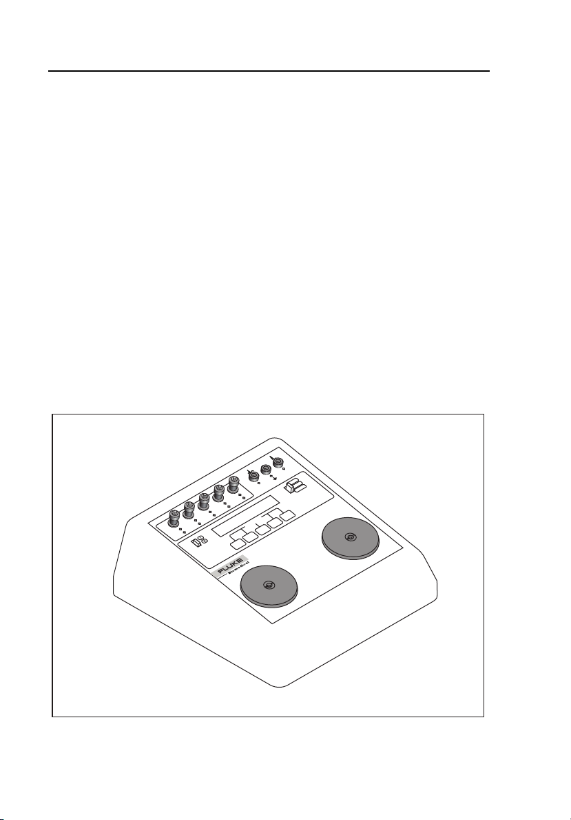
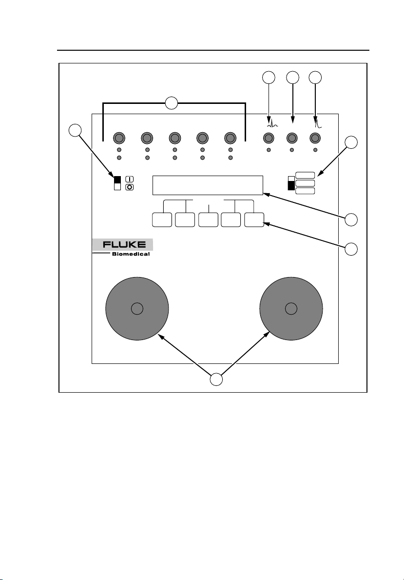
Instrument Familiarization
Figure 1-1 is an isometric illustration of the Analyzer, and the Front Panel
Layout is shown in Figure 1-2.
1-6
DEFIB
BATTERY / 9VDC
RA
ECG
RS-232 / 10101
V
C
LL
F
LA
L
RL
N
R
SOFTKEYS
QED-6
DEFIBRILLATOR ANALYZER
STERNUM (-)
PACER
1000 j
100 j
Figure 1-1. Analyzer Isometric View
APEX (+)
fcf013.eps
Page 19
Introduction and Specifications
Instrument Familiarization
2 3 4
1
BATTERY / 9VDC RS-232 / 10101
6
LL
LA
RL
RA
R
L
N
QED-6
DEFIBRILLATOR ANALYZER
F
SOFTKEYS
V
C
ECG
DEFIB
PACER
1000 j
100 j
1
5
7
8
STERNUM (-)
APEX (+)
9
fcf017.eps
Figure 1-2. Analyzer Front Panel Layout
1-7
Page 20

QED 6
Users Guide
Front Panel
The front panel of the Analyzer includes the elements described in Table 1-2.
Table 1-2. Front Panel Elements
Number Element Function
A
B
C
D
E Range switch
F Power switch Enables the Analyzer (I = ON, O = OFF).
G
H Five softkeys
Universal ECG
jacks
High Level
ECG Banana
jack
Common
Banana jack
Defib Scope
Out Banana
jack
LCD display:
24 characters x
2 lines.
Utilize AHA and International color coding,
allowing for waveform output to monitor/recorder.
Provides 1 volt peak output of the selected
waveform.
Provides ground for the “High Level ECG” and
“Defib Scope Out” jacks.
Provides pulse output to an oscilloscope.
Allows for defibrillator settings from 0 to 1000
joules (high), for power below 0-100 joules (low)
for increased accuracy, and a PACER range
setting for pacer output measurements.
The upper line of the LCD display provides
messages and test results, while the bottom line
displays menu choices.
Used to select the desired function highlighted on
the lower line of the display.
1-8
I
Two nickelplated
Defibrillator
Paddle Plates
Available for defibrillator paddle contact. All
waveforms are present at the paddle plates
simultaneously with the ECG jacks.
Page 21

Introduction and Specifications
Upgrading the Analyzer
1
Back Panel
The Back Panel includes a battery holder that houses a 9-volt alkaline battery,
and a dc battery eliminator jack. An RS232 D-9-pin serial port allows
communications to a computer, serial printer, or other Fluke test equipment.
Upgrading the Analyzer
A number of pre-configured Analyzer models are available. In addition, older
models may be upgraded by contacting the Fluke Biomedical Service Center.
Available Analyzer models are listed in Table 1-3.
Table 1-3. Available Analyzer Models
Model Characteristics
QED 6
QED 6M
QED 6H
Base unit. Features output energy, synchronization time, peak
measurements, bi-directional RS232.
Features output energy, sync time, peak measurements,
overshoot, bi-directional RS232, waveforms, charge time
measurements, 28 programmable autosequences.
Output energy, sync time, peak measurements, overshoot, bidirectional RS232, waveforms, charge time measurements, 28
programmable autosequences, pacer output measurements
and pacer refractory period measurements.
1-9
Page 22

QED 6
Users Guide
Specifications
The following are specifications for the Analyzer. Please contact your Fluke
Biomedical service representative for more information regarding the device
specifications.
General
Display.....................................................................2-line x 24-character LCD
Power ......................................................................One 9 V Alkaline (Duracell MN1604 or
Weight ....................................................................4.54 lb
Dimensions .............................................................26.67 x 24.13 x 10.16 cm
Environmental Operating Specs
Storage Temperature ..........................................-25 to 50 °C
Operating Temperature .......................................0 to 40 °C
Maximum Humidity..............................................90 % Relative Humidity
Output Power Measurement
Load Resistance......................................................50 Ω ±1 % non-inductance
Range
1000 J..................................................................0-1000.0 J
100 J....................................................................0-100.0 J
Resolution................................................................0.1 J
Max. Vage
1000 J..................................................................5500 V
100 J....................................................................1750 V
Max. Current
1000 J..................................................................110 A
100 J....................................................................35 A
Measurement...........................................................1000 J: 66 ±5 V
Trip Levels...............................................................100 J: 20 ±5 V
Pulse Width .............................................................1-50 ms
Accuracy
1000 J Range ......................................................±2 % of reading
100-1000 J .......................................................... ±2 Js
100 J Range ........................................................±2 % of reading
supertwist alphanumeric
equivalent); 12 hours continuous
operation; low battery indication; 9 V
battery eliminator input.
(< 10 µH), 160 W
±0.1 J
1-10
Page 23

Introduction and Specifications
Specifications
1
Synchronization Measurements
Range ..................................................................... 0-199.9 ms
Measurement.......................................................... From peak of R-wave
Accuracy ................................................................. 1 % of fullscale or ±2 ms
From base of R-wave
ECG Waveforms
QRS complex
Rates .................................................................. 30, 60, 120, 180, 240 BPM
Rate Accuracy .................................................... ±1 % of setting
Amplitude............................................................ Fixed at 1 mV Lead II
Amplitude Accuracy............................................ ±2 % (RA-LL)
(RA-LL)
Fixed at 1.1 mV
(Apex- Sternum)
±10 % (Apex-Sternum)
Performance Waveforms
Pulse....................................................................... 30, 60 BPM, pulse width 60 ms
Triangle Wave......................................................... 2 Hz
Square Wave ......................................................... 0.125 Hz, 2 Hz, 50 % duty cycle
Sine Waves............................................................. 10, 40, 50, 60, 100 Hz
Time Base Accuracy............................................... ±1 % of setting
Amplitude............................................................ Fixed at 1 mV Lead II
Amplitude Accuracy............................................ ±2 % (RA-LL)
(RA-LL)
(Triangle wave 2 mV Lead II)
(RA-LL)
Fixed at 1.1 mV
(Apex-Sternum)
±10 % (Apex-Sternum)
1-11
Page 24

QED 6
Users Guide
Defib Waveform Playback
Time Base Expansion .............................................100:1 @ 25 mm/sec paper speed;
Amplitude Scaling
Lead II (RA-LL)
1000 J Range ..................................................1 mV = 3000 V
100 J Range ....................................................1 mV = 900 V
ECG Output
1000 J Range ..........................................................0.5 V = 3000 V
100 J Range ............................................................0.5 V = 900 V
each division equals 40 ms
Arrhythmias
Afib, Vfib, Atach, Vtach, Aflutter, RUN, PVC, R on T, Idioventricular
Rate Accuracy .........................................................±1 %
Amplitude.................................................................Fixed at 1 mV Lead II
Amplitude Accuracy.................................................±2 (RA-LL) ±10 % (Apex-Sternum)
(RA-LL)
Fixed at 1.1 mV (Apex-Sternum)
Scope Outputs
ECG Hi-Level...........................................................Fixed at 1 V
Defib Output ............................................................Real Time
Pacer Range............................................................1 V = 3.11 V
1000 J Range ..........................................................1 V = 1450 V
100 J Range ............................................................1 V = 440 V
Amplitude Accuracy.................................................±2 % of scale
Accuracy: ±2 %
1-12
Page 25

Introduction and Specifications
Specifications
1
External Non-Invasive Pacer Measurements
Load........................................................................ 50 Ω ±1 %, non-inductive
R-wave Amplitude................................................... 1.1 mV ±10 % (Apex-Sternum)
Pulse Width............................................................. 1-50 ms
Peak Vage .............................................................. 0-12.5 V
Peak Current........................................................... 4-250 mA < 4 mA = 0.0 mA
Rate ........................................................................ 25-400 ppm < 25 ppm = 0 ppm
Refractory Period
Sensed................................................................ 110-500 ms < 110 ms = 110 ms
Pulsed................................................................. 70-500 ms < 70 ms = 70 ms
Accuracy ................................................................. ±2 % of fullscale for pulse width, peak
(< 10 µH) (Apex-Sternum)
1 mV ±2 % Lead II (RA-LL)
voltage current
±1 % of fullscale for rate and refractory
period measurements
Calibration Screen
Load........................................................................ 50 Ω ±1 % (Apex-Sternum)
Amplitude scaling.................................................... Apex (+) to Sternum (-)
Pacer Range....................................................... 318 counts/V
1000 J Range ..................................................... 0.683 counts/V
100 J Range ....................................................... 2.252 counts/V
Accuracy ................................................................. ±15 counts
Measurement Range .............................................. Apex (+) to Sternum (-)
Pacer Range....................................................... (0-12.86) = (0-4095)
1000 J Range ..................................................... (0-5995) = (0-4095)
100 J Range ....................................................... (0-1814) - (0-4095)
Zero Vage Input ...................................................... 0 ±2 counts
Peak / Overshoot
Vage Accuracy
1000 J Range ..................................................... ±10 V
100 J Range ....................................................... ±25 V
Current Accuracy .................................................... ±1 A
1-13
Page 26

QED 6
Users Guide
Accessories
The following are accessories for the Analyzer. To order, contact your Fluke
Biomedical equipment dealer and use the Fluke Biomedical part numbers
provided. Table 1-4 lists standard accessories shipped with the tester. Table
1-5 lists optional accessories that must be ordered separately.
Table 1-4. Standard Accessories
Description Qty Supplied Part Number
QEDR Tags 100 2241744
Users Guide 1 2204510
Warranty Card 1 NA
Internal Paddle Adapters 2 2204198
Table 1-5. Optional Accessories
Description Part Number
Carrying Case 2204282
RS232/Printer Cable, Serial 2204485
Printer (Seiko DPU 414-30B) 2248899
Printer Paper for DPU 414-30B 2248737
Converter Data, Serial-Parallel 110 V 2391907
Power Supply for DPU 414-30B Printer (110 V) 2235375
Automatic Paddle Adapters
Hewlett Packard 2200125
Marquette 2392362
Laerdhal 2392396
Physio Control (Automatic Defibrillation) 2392355
Physio Control (Pacer) 2230648
Zoll Cable Assembly 2200140
9 v dc, 300 mA Adapter 2527552
1-14
Page 27

Chapter 2
Operation
Contents Page
Introduction ................................................................................. 2-3
Powering Up................................................................................ 2-4
Adjusting Display Contrast.......................................................... 2-9
Measuring Defibrillator Energy................................................... 2-9
Evaluating Ability to Fire ............................................................ 2-12
Defibrillator Pulse Playback ........................................................ 2-14
Viewing Oscilloscope Output...................................................... 2-14
Preparation for Viewing........................................................... 2-14
Viewing a Test ......................................................................... 2-15
Measuring Synchronization ......................................................... 2-16
Generating Test Waveforms........................................................ 2-18
Testing High Level Out ............................................................... 2-20
Measuring Peak Voltage, Current, and Overshoot....................... 2-20
Measuring Charge Time (Models M and H)................................ 2-21
Pacemaker (Non-Invasive) Testing.............................................. 2-22
Pacemaker Refractory Period Testing ......................................... 2-24
Programming an Automatic Test Sequence................................. 2-26
Program Selection .................................................................... 2-27
Defib Setting ............................................................................ 2-28
Energy Limits........................................................................... 2-28
Charge Time............................................................................. 2-28
Sync Time ................................................................................ 2-29
Peak.......................................................................................... 2-29
Overshoot................................................................................. 2-29
ECG Performance .................................................................... 2-30
Pacer......................................................................................... 2-30
Running an Automatic Test Sequence......................................... 2-31
Printing the Analyzer Report Header........................................... 2-32
Resetting the Analyzer to Factory Defaults................................. 2-35
Remote Operation........................................................................ 2-36
Preparing for Serial Communications ...................................... 2-38
Ansur Software Control ........................................................... 2-39
2-1
Page 28

QED 6
Users Guide
2-2
Page 29

Operation
Introduction
2
Introduction
The Analyzer uses a 2-line x 24-character LCD display and softkeys to
simplify operation. See Figure 2-1.
Menu Choice Line
Test Results Line
BATTERY / 9VDC RS-232 / 10101
RA
R
RL
N
STERNUM (-)
LA
QED-6
DEFIBRILLATOR ANALYZER
LL
L
F
SOFTKEYS
Figure 2-1. Analyzer Front Panel Display
ECG
V
C
APEX (+)
DEFIB
PACER
1000 j
100 j
fcf014.eps
2-3
Page 30

QED 6
Users Guide
The top line of the LCD display is used for test results and the bottom line
provides menu choices.
The five-position softkey pad is used to control the functions of the instrument.
Make a menu selection by pressing the corresponding softkey. An audible
beep verifies the selection. The microprocessor scans the softkey keypad every
10 ms to check for softkey presses.
Powering Up
The Analyzer is powered by a 9-volt alkaline battery. An external power jack
is provided for use with a 9 V dc modular power source that plugs into the ac
line. Plugging into this jack mechanically disconnects the battery.
The low battery detection circuit outputs a low level digital signal when the
battery voltage reaches 6.1 volts. This signal is polled along with the function
softkeys every 10 ms and, if a low battery condition occurs, the display
indicates WARNING - LOW BATTERY!! To continue, replace the battery or
use an external power source.
Upon power-up, the microprocessor receives software instructions from the
resident firmware and provides information to the user on the Analyzer display
or on a remote display via the serial port. The following message appears
briefly on the display, identifying the software version:
fcf001.eps
After a short delay, the display changes to Main Menu 1:
fcf002.eps
Explore the functions of the softkeys and the menus, as follows:
1. Press the ENERG, SYNC, PEAK or WAVE softkey to access a submenu
of specific functions.
2. Press more to toggle between Main Menu 1 and Main Menu 2.
2-4
Page 31

Operation
Powering Up
3. Press esc in any submenu to return to the previous menu and, ultimately,
to Main Menu 1.
Figures 2-2 and 2-3 provide overviews of the menus and functions associated
with Main Menu 1 and Main Menu 2, respectively. Figure 2-4 provides an
overview of the Autosequence menu structure, accessed from the AUTO
option of Main Menu 2.
2
2-5
Page 32

QED 6
Users Guide
2-6
Figure 2-2. Main Menu 1 Functions
fcf018.eps
Page 33

Operation
Powering Up
2
Figure 2-3. Main Menu 2 Functions
2-7
fcf003.eps
Page 34

QED 6
Users Guide
2-8
Figure 2-4. Autosequence Menu Structure (Main Menu 2)
fcf004.eps
Page 35

Operation
Adjusting Display Contrast
2
Adjusting Display Contrast
Display contrast on the Analyzer may be adjusted to optimize viewing of
menus and test data.
To set the display contrast:
1. From Main Menu 2, press the UTIL softkey to display the following:
2. Press the DISP softkey to access the display Contrast menu:
3. Press the + softkey to increase the numerical value and decrease the
contrast; press the – softkey to decrease the numerical value and increase
the contrast. The default is 5.
4. Press the esc softkey to store the last displayed value in memory.
Measuring Defibrillator Energy
To measure defibrillator energy:
1. Power up the defibrillator to be tested and select the energy output
according to the manufacturer’s instructions.
2. Power up the Analyzer.
3. From Main Menu 1, press the ENRG softkey to access the Energy
menu:
fcf055.eps
fcf057.eps
2-9
Page 36

QED 6
Users Guide
fcf006.eps
4. Press the WAV> softkey to browse through a list of available waveforms
in Energy Mode. These waveforms are described in Table 2-1.
Table 2-1. Available Waveforms
Waveform Description
ECG90 The default waveform; after a discharge, the ECG90 resumes.
VFIB Ventricular Fibrillation
VTACH 125 BPM, VTACH
VTAC2 240 BPM, Monomorphic
VTAC3 300 BPM, Polymorphic
ASYS Asystole
The waveform appears through the ECG adapters and Analyzer front
panel paddles and is available to trigger an automatic defibrillator to
discharge.
After the defibrillator discharges, the output switches to a 90 BPM ECG
waveform. If the range switch is set to Pacer, the following message
appears momentarily:
4. Set the range switch appropriately, as follows:
• Select the 1000 joule high range (1000 J) for defibrillator outputs
over 100 joules or for an unknown defibrillator output power.
• Select the 100 joule low range (100 J) for outputs under 100 joules.
5. Simultaneously press the two defibrillator paddles onto the contact
electrode plates on the front of the Analyzer. See Figure 2-5.
2-10
fcf007.eps
Page 37

Operation
Measuring Defibrillator Energy
B
I
F
E
D
G
EC
1
0
1
0
/ 1
2
3
-2
S
R
DC
V
9
/
Y
R
E
L
T
L
T
A
B
F
A
L
L
L
R
N
A
R
R
ER
C
A
P
j
0
0
0
1
V
j
0
0
1
C
OFTKEYS
S
YZER
NAL
R A
O
T
ILLA
QED-6
EFIBR
D
)
-
(
M
U
N
ER
T
S
Defibrillator/Pacer
)
+
(
EX
P
A
DEFIB
OFF
PACER
2
fcf008.eps
Figure 2-5. Defibrillator Energy Testing
6. Initiate a discharge from the defibrillator.
7. Observe the output settings and the actual readings displayed on the
Analyzer and record them on the QEDR Performance Tag as shown in
Figure 2-6.
2-11
Page 38

QED 6
Users Guide
Fluke Biomedicals
Figure 2-6. QEDR Performance Tag
Note
The Analyzer continues to display the reading until the next
defibrillator pulse is fired.
fcf009.eps
Evaluating Ability to Fire
This test evaluates an automatic defibrillator for its ability to fire automatically
after recognizing ventricular fibrillation and / or ventricular tachycardia.
To test the ability of the defibrillator to fire automatically:
1. Attach the optional automatic defibrillator paddle adapters to the
Analyzer.
2. Connect the ECG patient leads to the Analyzer, as shown in Figure
2-7.
2-12
Page 39

Operation
Evaluating Ability to Fire
2
DEFIB
PACER
OFF
Defibrillator/Pacer
DEFIB
ECG
R
CE
A
P
1000 j
RS-232 / 10101
C
Y / 9VD
R
LA
ATTE
B
L
RL
N
RA
R
100 j
V
C
LL
F
SOFTKEYS
YZER
L
OR ANA
T
QED-6
DEFIBRILLA
APEX (+)
STERNUM (-)
fcf010.eps
Figure 2-7. ECG Lead Configuration
3. From the Energy menu, press the WAV> softkey until the VFIB option
appears; then press the VFIB softkey.
A ventricular fibrillation waveform is simulated by the Analyzer through
the ECG jacks and paddle plates. When a discharge is complete, the
Analyzer outputs a 90 BPM Normal Sinus Rhythm.
4. Press the WAV> softkey until the VTACH option appears; then press the
VTACH softkey.
A ventricular tachycardia is simulated by the Analyzer through the ECG
jacks and paddle plates. When the discharge is complete, the Analyzer
outputs a 90 BPM Normal Sinus Rhythm.
2-13
Page 40

QED 6
Users Guide
Defibrillator Pulse Playback
The Analyzer allows the user to play the defibrillator pulse waveform for the
purpose of analysis. Playback is accomplished using a strip recorder or
defibrillator monitor through the ECG jacks or scope output. The waveform
can also be reviewed on an oscilloscope through the high-level ECG outputs.
To play back the defibrillator pulse:
1. Power up the defibrillator and the Analyzer.
2. From Main Menu 1, press the ENRG softkey to access the Energy
menu, and press the WAV> softkey to access the WAV submenu.
3. Connect the ECG patient leads to the Analyzer as shown in Figure 2-7.
4. After the defibrillator discharges, press the PLAY softkey. The last
defibrillator pulse is replayed.
Viewing Oscilloscope Output
The Analyzer provides two banana jacks for real-time viewing on an
oscilloscope with storage capability
To view the output on an oscilloscope, carry out the steps under each of the
subheadings, below:
Preparation for Viewing
1. Connect the Oscilloscope to the Analyzer, using a banana plug and a
scope probe to ensure signal integrity, as indicated:
• Ground – Attach the ground from the scope probe to the common
(black) jack on the Analyzer.
• Output – Attach the positive lead of the scope probe to the
defibrillator output.
2-14
Page 41

Operation
Viewing Oscilloscope Output
2
2. Make the following settings:
a. Set the oscilloscope trigger on external and connect a lead between
the input of the oscilloscope and the external trigger input.
b. Set the time scale on the oscilloscope to 1 ms / division and adjust to
the desired expansion after observing the waveform output.
c. Set the gain on the oscilloscope to 0.2 v / division and adjust to the
desired level after observing the waveform.
3. Activate the storage control on the oscilloscope.
4. For most applications, set the oscilloscope input coupling control to ac
mode.
Note
If the defibrillator under test uses a discharge waveform with sizable
dc components (trapezoidal or pulsatile discharge), improved output
waveform fidelity can be obtained by placing the oscilloscope in the
dc-coupling mode.
Viewing a Test
1. Initiate a test by following the steps described under Measuring
Defibrillator Energy, above.
The waveform is 1/1450 when in the 1000 joule range and 1/440 in the
100 joule range of the input voltage through 50 Ω. The actual magnitude
of the discharge voltage can be obtained by using the following equation:
V
V
discharge
discharge
= V
= V
(1450) High range
scope
(440) Low range
scope
2. Observe the waveform as it appears on the oscilloscope. Repeatedly
discharge the defibrillator while adjusting the time and the gain to the
optimal scale for observing the waveform.
Note
If the waveform does not appear on the oscilloscope, readjust the
trigger levels on the oscilloscope and repeat the appropriate steps in
the procedure.
2-15
Page 42

QED 6
Users Guide
Measuring Synchronization
The Analyzer measures the synchronization time (cardioversion delay time) of
synchronized defibrillators. A 90 BPM ECG waveform is output through the
ECG jacks and the paddle plates. During normal operation, the defibrillator
recognizes and responds to this trigger by discharging within a certain amount
of time.
The Analyzer is capable of measuring up to 199.9 ms in delay time from either
the peak or the base edge of the R wave. Typical acceptable delay times are
within 60 ms from the peak of the R wave.
To measure synchronization:
1. Turn the defibrillator to be tested to ON and select the desired energy
output in accordance with the manufacturer’s instructions.
2. Connect the ECG patient leads to the Analyzer as shown in Figure 2-7.
3. Power up the Analyzer by sliding the power switch forward to the ON
position. The Analyzer displays Main Menu 1:
4. Press the SYNC softkey to enter the Sync menu:
2-16
fcf002.eps
fcf011.eps
Page 43

Operation
Measuring Synchronization
2
Sync time measurements are performed as shown in Figure 2-8, below:
QRS COMPLEX
90 BPM NSR
R
Q
DEFIB PULSE
R-Wave Time
Q-Wave Time
Figure 2-8. Sync Time Measurements
Defib
Pulse
Peak
fcf019.eps
5. Set the range switch appropriately, as follows:
• Select the 1000 joule high range for defibrillator outputs over 100
joules or for an unknown defibrillator output power.
• Select the 100 joule low range for outputs under 100 joules.
6. Place the defibrillator in synchronous mode.
7. Simultaneously press both defibrillator paddles to the contact plates of the
Analyzer.
8. Initiate a discharge from the defibrillator.
9. Press the ENRG softkey to view the energy readings on the display, as
shown below.
2-17
Page 44

QED 6
Users Guide
fcf020.eps
Note
The LCD displays the reading for about two seconds.
Generating Test Waveforms
The Analyzer generates a series of test waveforms designed to verify the
accuracy of ECG machine / monitors. These waveforms, shown in Table 2-2 ,
are available for simulation via ECG jacks or paddle plates and are calibrated
for lead II at 1 mV.
Table 2-2. Test Waveforms
ECG Performance Arrhythmia
30 BPM 30 BPM Pulse Atrial Fibrillation
60 BPM 60 BPM Pulse Atrial Flutter
120 BPM 2 Hz Triangle (2 mV) Atrial Tachy
180 BPM 0.125 Hz Square (50 % dc) Idioventricular
240 BPM 2.0 Hz Square (50 % dc) PVC
10 Hz Sine R on T
40 Hz Sine Run
50 Hz Sine Ventricular Fib.
60 Hz Sine Ventricular Tachy
100 Hz Sine
To generate waveforms for testing:
1. Turn the defibrillator to be tested to ON.
2. Connect the ECG patient leads to the Analyzer as shown in Figure 2-7.
2-18
Page 45

Operation
Generating Test Waveforms
3. Power up the Analyzer by sliding the power switch forward to ON. Main
Menu 1 displays:
2
4. Press the WAVE softkey to access the Waveform Type menu:
5. Press the softkey corresponding to the desired wave simulation:
• ECG for ECG waveforms
• PERF for performance waveforms
• ARRH for arrhythmia waveform
For example:
To select the next available option within a waveform simulation, press
the UP softkey; to select a previous option, press the DOWN softkey.
6. Observe the waveform on the monitor under test.
fcf002.eps
fcf022.eps
fcf023.eps
Note
The selected waveform plays continuously until another is selected or
until the esc softkey is pressed.
2-19
Page 46

QED 6
Users Guide
Testing High Level Out
All waveforms available through the ECG jacks are simultaneously output
through the High Level jacks. This scheme offers the user a 1-volt peak signal
for testing purposes.
To test a High Level signal, use an oscilloscope and a scope probe to measure
the output waveform on the high level output. Refer to Generating Test
Waveforms, above, for procedure.
Note
Use a scope probe to guarantee signal integrity.
Measuring Peak Voltage, Current, and Overshoot
To measure the peak voltage and current of the defibrillator pulse:
1. Power up the defibrillator to be tested and select the energy output,
following the manufacturer’s instructions.
2. Power up the Analyzer. Main Menu 1 displays:
3. Press the PEAK softkey to access the --- V --- A (current and voltage)
menu:
Pressing the Peak / OVER softkey toggles the measurement between
Peak current and voltage and Over current and voltage.
2-20
fcf002.eps
fcf025.eps
Page 47

Operation
Measuring Charge Time (Models M and H)
4. Set the range switch appropriately, as follows:
• Select the 1000 joule high range for defibrillator outputs over 100
joules or for an unknown defibrillator output power.
• Select the 100 joule low range for outputs under 100 joules.
5. Simultaneously press the two defibrillator paddles onto the contact
electrode plates on the front of the Analyzer.
6. Initiate a discharge from the defibrillator.
7. Observe the LCD on the Analyzer and record the defibrillator voltage and
current.
Note
The LCD continues to display the reading until the next defibrillator
pulse is fired.
2
Measuring Charge Time (Models M and H)
To measure the charge time of Models M and H:
1. From Main Menu 1, press more to access Main Menu 2. The following
displays:
2. From Main Menu 2, press the CHRG softkey to display the following:
3. Set the range switch appropriately, as follows:
• Select the 1000 joule high range for defibrillator outputs over 100
joules or for an unknown defibrillator output power.
• Select the 100 joule low range for outputs under 100 joules.
2-21
fcf026.eps
fcf027.eps
Page 48

QED 6
Users Guide
4. Press the two defibrillator paddles onto the contact electrode plates on the
front of the Analyzer.
5. Press the START softkey and initiate the defibrillator charge cycle.
6. As soon as the defibrillator reaches full charge, discharge it, noting the
time (in seconds) on the display. The maximum for the Analyzer is 60
seconds. After 60 seconds, the Analyzer displays OVER.
Pacemaker (Non-Invasive) Testing
1. From Main Menu 1, press more to access Main Menu 2. The following
displays:
fcf026.eps
2. Set the range switch to pacer. Otherwise the unit displays the following
message:
fcf029.eps
3. From Main Menu 2, press the PACE softkey to display the Pacer
Tests menu:
fcf030.eps
4. Connect the output from the pacer to the Analyzer, as shown in Figure
2-9.
2-22
Page 49

Operation
Pacemaker (Non-Invasive) Testing
ECG Leads
RA LA LL
Pacer
Output
BATTERY / 9VDC RS-232 / 10101
LL
FLALRLNRAR
SOFTKEYS
QED-6
DEFIBRILLATOR ANALYZER
ECG
V
C
PACER
DEFIB
1000 j
100 j
2
STERNUM (-)
Pacer
Adapters
APEX (+)
Figure 2-9. Connecting Pacemaker Output to Analyzer
Note
The Pacer can be in either demand or non-demand mode.
5. Press the MEAS softkey to display the following:
Three hyphens (---) indicate that no pacer pulses were received.
6. Set the pacer at various current and heart rate settings. The results are
displayed. Press the PRINT softkey for a hard copy.
fcf015.eps
fcf031.eps
2-23
Page 50

QED 6
Users Guide
Note
Pacer voltage and current are displayed as average voltage and
current. If a printer is connected to the Analyzer, the printout also
documents peak voltage and current. If computer control is being
used, no peak values are available. All voltage measurements are
Ω
referenced to the internal 50
load.
Pacemaker Refractory Period Testing
To test the pacer refractory period:
1. Set the pacer in demand mode.
2. From Main Menu 1, press more to access Main Menu 2. The following
displays:
fcf026.eps
3. Set the range switch to pacer. Otherwise the unit beeps and displays the
following message:
fcf029.eps
4. From Main Menu 2, press the PACE softkey to display the Pacer
Tests menu:
fcf032.eps
5. Press RFP to select refractory period testing. Refer to Figure 2-9 for
setup. The following menu appears.
2-24
Page 51

Operation
Pacemaker Refractory Period Testing
2
Three hyphens (---) indicate that no pacer pulses have been received.
Definitions of the other abbreviations on the display are:
• PRP – Pulsed refractory period; the time (typically 20-500 ms)
after a pulse is delivered from the pacemaker, during which the
pacemaker does not detect cardiac activity.
• PPM – pacing rate at which the test was performed
• SRP – sensed refractory period; the period after the pacemaker
senses cardiac activity during which it does not detect further
cardiac activity.
6. Press the TEST softkey to start testing. The dashed lines flash, indicating
that the test is in progress and pulses are detected. When the refractory
period has been determined, the results are displayed.
Note
At slow rates, it may take one to three minutes to determine the
refractory tests. The test is quicker at higher pacing rates. The results
are automatically output via the RS232 port. Do not alter the pacing
rate during refractory measurements or incorrect data may be
recorded.
fcf033.eps
2-25
Page 52

QED 6
Users Guide
Programming an Automatic Test Sequence
The Model H can store in memory up to 28 automatic sequences to fully test
defibrillator performance according to protocol. Standard defaults for
Programs 0-27 for the Model H are listed in Table 2-3.
Table 2-3. Autosequencing Defaults (Model H)
Performance Parameter Default
Print Heading Yes
Energy Measurements 10 J
100 J
200 J
300 J
360 J
Energy Limits + / - 5%
Charge Time Yes
Sync Time Yes
Peak No
Overshoot No
ECG performance 30 BPM
120 BPM
240 BPM
2 Hz Sq
.125 Hz Sq
10 Hz Sin
40 Hz Sin
50 Hz Sin
60 Hz Sin
100 Hz Sin
2 Hz Tri
60 BPM PLS
Fib
Pacer No
2-26
Page 53

Operation
Programming an Automatic Test Sequence
To program an automatic test sequence, carry out the following steps and those
listed under individual headings, below:
1. From Main Menu 2, press the AUTO softkey to display the
Autosequences menu:
2
2. Press the PROG softkey to access the individual programs to be modified.
fcf034.eps
fcf035.eps
Program Selection
1. Select the automatic test sequence to be modified by pressing the + or softkeys to increase / decrease program numbers.
Available programs are named PROG and numbered 0-27, but you can
press the NAME softkey and modify the program name and number.
2. Press the SEL softkey to confirm the program selected for modification
and to attach a header.
You are asked if you wish to attach a header to the data to be output after
the test sequence has been run.
3. Press the SEL softkey to toggle between Yes and No.
2-27
fcf036.eps
Page 54

QED 6
Users Guide
Defib Setting
1. Press STEP to advance to the next check item, Defib Setting.
2. Press + or - to increase or decrease the defib setting.
3. Press NEXT for the next defib setting.
Energy Limits
1. Press STEP to advance to the next check item, Limit.
2. Press the + or - softkeys to increase / decrease the accuracy limit.
Charge Time
1. Press STEP to advance to the next check item, Charge Time.
fcf037.eps
fcf038.eps
2. Press the SEL softkey to toggle between Yes and No.
2-28
fcf039.eps
Page 55

Operation
Programming an Automatic Test Sequence
Sync Time
1. Press STEP to advance to the next check item, Sync-Time.
2
2. Press the SEL softkey to toggle between Yes and No.
Peak
1. Press STEP to advance to the next check item, Peak.
2. Press the SEL softkey to toggle between Yes and No.
Selecting Yes includes Peak Voltage and Peak Current
measurements.
Overshoot
1. Press STEP to advance to the next check item, Overshoot.
fcf040.eps
fcf041.eps
2. Press the SEL softkey to toggle between Yes and No.
2-29
fcf042.eps
Page 56

QED 6
Users Guide
ECG Performance
1. Press STEP to advance to the next check item, ECG/Perf.
fcf043.eps
2. Press + or - to advance to the next waveform.
3. Press SEL to program / deprogram a waveform. An * indicates that the
item is programmed.
Pacer
1. Press STEP to advance to the next check item, Pacer.
2. Press the SEL softkey to toggle between Yes and No.
3. Press STEP to return to the program menu.
4. Press the esc softkey. You are asked, “Save Changes?”
fcf044.eps
fcf045.eps
5. Press the YES softkey to save the program or the NO softkey to return
without saving; both return to the Autosequences menu:
fcf046.eps
6. Press the esc softkey to return to Main Menu 2.
2-30
Page 57

Operation
Running an Automatic Test Sequence
Note
The changes are saved until the program is modified again, or the
Analyzer is reset to factory defaults.
Running an Automatic Test Sequence
To run an automatic test sequence:
1. From Main Menu 2, press the AUTO softkey to display the
Autosequences menu:
2
2. Press the RUN softkey to select an autosequence program, which are
numbered 0 - 27.
3. Press the + or - softkey to increase / decrease the program numbers.
4. When the desired program number displays, press the START softkey to
start the selected program.
The Analyzer prompts the user through the complete autosequence
program. Data output (if requested) to a printer or computer occurs after
the test sequence has been run.
Note
If the range switch is not already set to the appropriate range or to
pacer for PACE tests, the Analyzer sounds an audible alarm, and a
warning message appears until the condition is corrected.
fcf046.eps
fcf047.eps
2-31
Page 58

QED 6
Users Guide
Printing the Analyzer Report Header
All test reports created by the Analyzer can be printed via the RS232 port.
To print the report header:
1. From Main Menu 1, press the ENRG softkey to access the Energy
menu:
fcf006.eps
2. Press the HDR softkey to forward the header via the serial port to the
target device (computer or serial printer).
To print a report header from the Pacer menu:
1. From Main Menu 1, press the more softkey to access Main Menu 2:
fcf026.eps
2. Press the PACE softkey to access the Pacer menu:
3. Press the HDR softkey to forward the header via the serial port to the
target device (computer or serial printer).
An example of a standard printout (manual operation) with a header is
shown in Figure 2-10. During manual operation, results are output to the
printer (or computer) immediately after each test is performed.
Note
These results do not appear on the display when no printer or
computer is attached to the Analyzer.
An example of a standard printout (automatic sequence) with a header is
shown in Figure 2-11. In Autosequencing mode, all results are output to
the printer (or computer) after the sequence is complete.
2-32
Page 59

Operation
r
Printing the Analyzer Report Header
Fluke Biomedical
Control #:
Serial #:
Model #:
Mfr.
Location:
Technician :
Date:
Setting Actual
--------- 20.0 J
Qwave Sync Time 43.9 ms
Rwave Sync Time 73.1 ms
Energy 19.9 J
Over Voltage 0 V
Over Current 0 A
Energy: 19.9 J
PACER OUTPUT MEASUREMENTS
Pulse Rate: 40 PPM
Pulse Width: 19.7 ms
Peak Current: 18.0 ma
Peak Voltage: 0.9 V
Ave Current 0.0 ma
Ave Voltage: 0.0 V
PACER REFRACTORY MEASUREMENTS
Selected Pacing Rate: 40 PPM
Pulsed Refractory Period: 329.2 ms
Sensed Refractory Period: 179.2 ms
Charge Time: 05 sec
Energy: 19.8 J
Heade
2
fcf050.eps
Figure 2-10. Manual Output with Header
2-33
Page 60

QED 6
Users Guide
Fluke Biomedical
Control #:
Serial #:
Model #:
Mfr.
Location:
Technician:
Date:
PROGRAM NAME: PROG 5
Setting Actual Limit +/- 5%
10 J 10.3 J
100 J 10.3 J
200 J 199.0 J
300 J 300.0 J
360 J 360.0 J
Charge Time: 5 sec 198.3 J
Qwave Sync Time 21.0
Rwave Sync Time 50.0
Peak Voltage: 2270 V
Peak Current: 45 A
OVER Voltage: 2 V
OVER Current: 2 A
ECG/Performance Waves
30 BPM
120 BPM
240 BPM
2 Hz Sq
.125 Hz Sq
10 Hz Sin
40 Hz Sin
50 Hz Sin
60 Hz Sin
100 Hz Sin
2 Hz Tri
60 BPM Pls
Vfib
Figure 2-11. Automatic Sequence Output with Header
fcf051.eps
2-34
Page 61

Operation
Resetting the Analyzer to Factory Defaults
PACER OUTPUT MEASUREMENTS
Pulse Rate: 40 PPM
Pulse Width: 0.0 ms
Peak Current: 0.0 ma
Peak Voltage: 0.0 V
Ave Current 0.0 ma
Ave Voltage: 0.0 V
PACER REFRACTORY MEASUREMENTS
Selected Pacing Rate: 40 PPM
Pulsed Refractory Period: 329.2 ms
Sensed Refractory Period: 195.4 ms
Figure 2-11. Automatic Sequence Output with Header (cont.)
Resetting the Analyzer to Factory Defaults
To reset the Analyzer defaults:
1. From Main Menu 2, press the AUTO softkey to display the
Autosequences menu:
2
fcf054.eps
fcf048.eps
2. Press the DEFS (defaults) softkey to access the restore menu.
fcf049.eps
3. Select one of the following options:
• Press (ALL) to restore all 28 factory default programs.
• Press + to scroll through the programs; stop when the desired
program name appears.
2-35
Page 62

QED 6
Users Guide
• Press No or esc to back up one menu level.
• Press OK to restore the selected program to factory defaults. The
Analyzer displays a confirmation message that defaults are loading.
4. When finished, press esc once to return to the Autosequences menu
or twice to return to Main Menu 2.
Remote Operation
The Analyzer RS232 bi-directional interface allows communications with a
PC, allowing the PC to send commands to the Analyzer. Such operation
requires a Fluke RS232 cable and a bi-directional D-9 connector. The RS232
serial communications port originates from the microprocessor asynchronous
serial port 0.
When the parameters are properly set, test data gathered by the Analyzer is
automatically sent to the PC via the RS232 port for inclusion in a test form.
The information sent to the computer is identical to the data sent to the printer.
During operation, the Analyzer senses that an RS232 cable or printer is
attached and sends data to the appropriate device. If neither is attached, test
data appears on the display.
Note
The null modem supplied with the Fluke serial cable is not required
when data is being transferred to a computer.
The Data Computer Equipment (DCE) wiring configuration is shown in Table
2-4.
2-36
Page 63

Operation
Remote Operation
Table 2-4. Serial Port Wiring Configuration
Pin Function
1 Unused
2 RX
3 TX
4 DTR
5 Unused
6 Unused
7 Unused
8 Serial
9 232 Ground
2
Use the Fluke serial cable to transfer data from the Analyzer serial port to any
IBM (or compatible) computer or printer. The Data Terminal Equipment
(DTE) wiring configuration is shown in Table 2-5.
Table 2-5. Serial Cable Wiring Configuration
Pin Function
1 Unused
2 TX
3 RX
4 RTS
5 CTS
6 DSR
7 232 Ground
8-25 Unused
The communications protocol is user-configurable, and the setup is performed
by software internal to the processor.
2-37
Page 64

QED 6
Users Guide
Preparing for Serial Communications
Several steps are required to prepare the Analyzer for serial communications
with an attached computer. The first is setting parameters for RS232 data
transfer.
Note
Ensure that the Baud Rate, Parity, Data, and Stop Bits settings
selected for the Analyzer match those set on the computer.
To set RS232 parameters on the Analyzer:
1. From Main Menu 1, press more to access Main Menu 2. The following
displays:
2. From Main Menu 2, press the UTIL softkey to display the following:
3. Press the R232 softkey to display the following:
2-38
fcf026.eps
fcf055.eps
fcf056.eps
Page 65

Operation
Remote Operation
4. Press the softkey corresponding to the parameter to be changed. Repeated
pressing of the softkey cycles through the settings. The following settings
are recommended:
• Baud Rate: 300, 600, 1200, 2400, 9600
• Parity: None, Even, Odd
• Stop Bits: 1 or 2
• Data Bits: 7 or 8
The Analyzer factory default setting is 2400, N, 8, 1.
5. Press the esc softkey to store the last displayed parameters in memory.
6. Press esc to return to Main Menu 2.
2
Ansur Software Control
Ansur test automation systems allow a solutions-based approach to complete
testing of the medical device under test (DUT). Ansur helps you create
standard work using the test template/sequence (which is based on your written
test procedure) and integrates all test results into a single test report that can be
printed or archived. Ansur manages test procedures by allowing both manual
and visual automated test sequences.
The software works hand-in-hand with Fluke Biomedical testers and
simulators, creating a seamless integration for:
• Visual inspections
• Preventive maintenance
• Work procedures
• Performance tests
• Safety tests
Ansur software utilizes plug-in modules to work with a wide array of Fluke
Biomedical instruments. The plug-in module is a software interface to the
Ansur program. Plug-ins provide test elements used by Ansur. This gives the
benefit of using the same user interface for all testers and simulators supported
by an Ansur plug-in. See the Fluke Biomedical Ansur QED 6 Plug-in User
Manual for detailed information.
2-39
Page 66

QED 6
Users Guide
When you purchase a new Fluke Biomedical tester or simulator, you can
update your existing Ansur software by installing a new plug-in. Each plug-in
module lets you work only with the options and capabilities you need for the
instrument you are testing.
2-40
Page 67

Chapter 3
Maintenance, Service, and
Calibration
Contents Page
Maintenance................................................................................. 3-3
Avoiding Damage .................................................................... 3-3
Cleaning ................................................................................... 3-3
Troubleshooting........................................................................... 3-4
Service and Calibration................................................................ 3-5
3-1
Page 68

QED 6
Users Guide
3-2
Page 69

Maintenance, Service, and Calibration
Maintenance
3
Maintenance
The Analyzer requires little maintenance or special care; however, it is a
calibrated measuring instrument and should be treated as such. The optional
carry case is recommended for storage. It is further recommended that the
storage environment be free from vibration.
Avoiding Damage
Do not drop the instrument or subject it to any mechanical abuse that could
cause a shift in the calibrated settings.
W Caution
To avoid damage to the Analyzer or adverse affects on its
performance, do not expose the system to temperature
extremes. Ambient temperatures should remain between –
25 °C and 50 °C, with a relative humidity less than 90 %.
Cleaning
Clean the exterior of the Analyzer occasionally with a cloth dampened with a
mild detergent solution.
W Caution
To avoid damage to the Analyzer or adverse affects on its
performance, do not spray liquid directly on or immerse
the unit.
Carefully wipe down the cables and inspect them for damage and deterioration
of the insulation. Check the cable connections for integrity.
3-3
Page 70

QED 6
Users Guide
Troubleshooting
This section provides a brief troubleshooting guide to help you pinpoint
potential problems with the Analyzer. Refer any additional problems to the
Fluke Biomedical Service Center.
Description Cause Action
WARNING – LOW
BATTERY!! appears on
display
Two beeps per second
on power up
Four beeps per second
on power up
Infrequent resets during
operation
Low battery Replace battery
Defective or incorrectly
inserted RAM
Defective,
misprogrammed, or
incorrectly inserted
EPROM
High EMI fields
produced by defibrillator
units
Call the Fluke
Biomedical Service
Center
Call the Fluke
Biomedical Service
Center
Reset the power on the
Analyzer and continue
operation
3-4
Page 71

Maintenance, Service, and Calibration
Service and Calibration
3
Service and Calibration
If the new Analyzer fails to operate successfully or if it needs a recommended
yearly calibration, please contact the Fluke Biomedical Service Center
immediately, as indicated under Warranty and Product Support.
W Caution
To avoid damage to the Analyzer or adverse affects on its
performance, allow only qualified technical personnel to
service the Analyzer.
Battery Replacement
The replacement battery for the Analyzer is a standard 9 V alkaline battery.
XW Warning
To avoid possible electrical shock or personal injury,
disconnect all test leads and the ac adapter before
opening the battery door.
To replace the battery:
1. Disconnect all test leads and the ac adapter from the Analyzer.
2. Open the battery compartment door on the back panel.
3. Remove the battery, disconnecting it from the snap contacts.
4. Connect the 9 V alkaline replacement battery to the snap contacts.
5. Place the battery into the compartment and close the door until it clicks.
Packing
If repairs or calibration are required, return the Analyzer to the factory or the
nearest service center.
1. Before returning the Analyzer for factory service, contact Fluke
Biomedical Service Center for a required Return Authorization Number.
2. Provide the following information:
• The Analyzer serial number
• The specific steps that reproduce your problem
3-5
Page 72

QED 6
Users Guide
• A daytime phone number
• Your name / company
• A fax number (if available)
3. Pack the instrument carefully, using the original shipping container and
packing materials supplied by Fluke Biomedical. If the original packing
materials are not available, refer to Return Procedures for a list of
preferred materials or contact Fluke Biomedical for replacement packing.
Note
Failure to pack the instrument properly could void the warranty.
Shipping
1. Place the Return Authorization Number in a prominent place on the
outside of the packing box, and refer to the number in any correspondence
with Fluke Biomedical Service.
2. Enclose your return address and Return Authorization Number.
3. Insure the unit for full retail value and ship to the nearest Fluke
Biomedical Service Center.
3-6
 Loading...