

Page 1
®
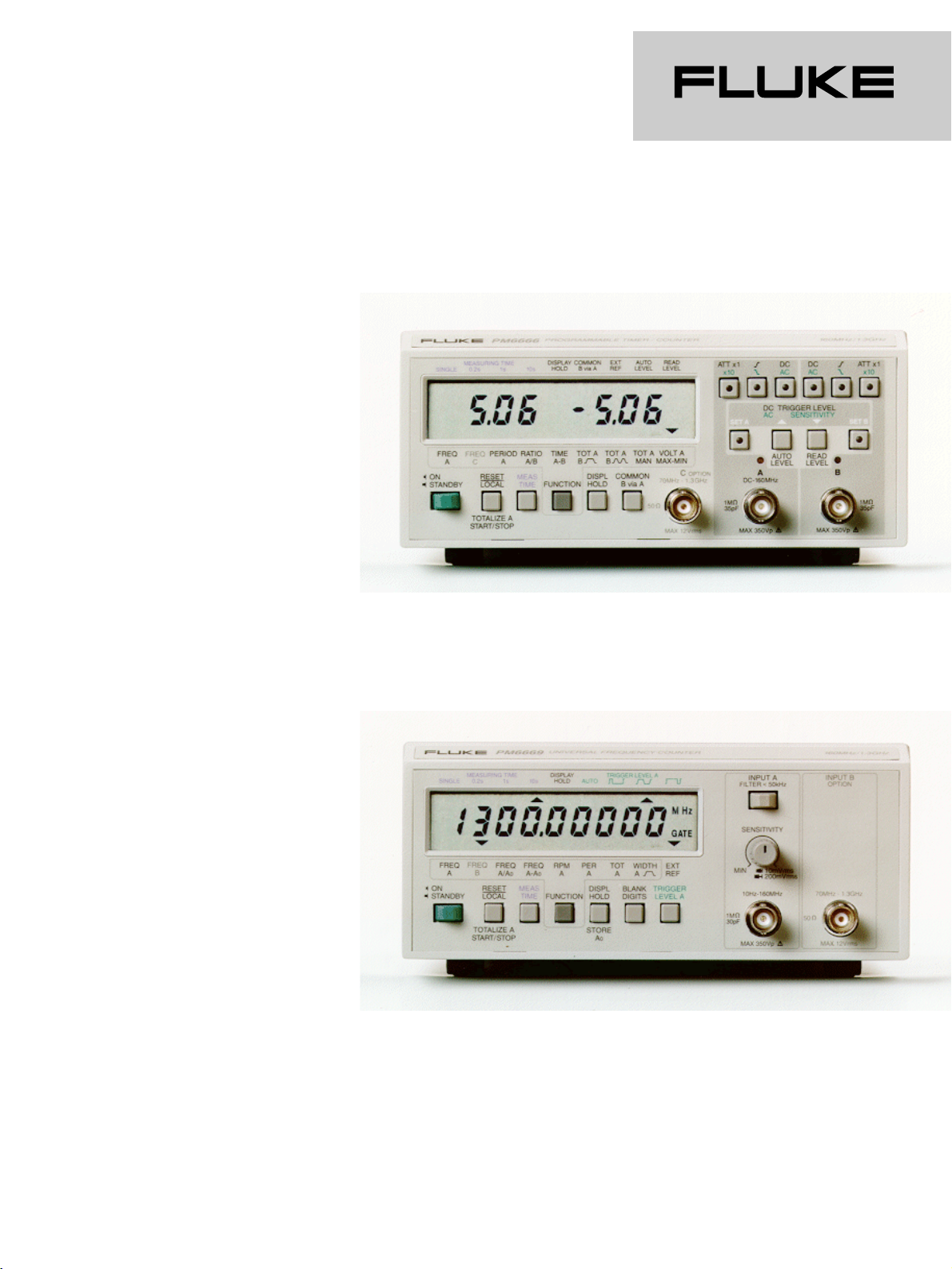
PM 6666
Programmable Timer / Counter
PM 6669 Frequency Counter
Technical Data
•
Unrivaled price/performance
•
160 MHz / 1.3 GHz option
•
Reciprocal counting, 7 digits per second
•
High stability MTCXO: 2x10⁻⁷over 0°C to 50°C with push-button calibration
•
Error-free triggering-, high noise immunity input circuitry
•
PM 6666: Full GPIB/IEEE 488 programmability, Auto trigger, Voltage measurements
•
PM 6669 Ease of operation, auto triggering, auto range and auto display
•
Rugged, no compromise quality, MTBF 50.000h & 70.000h
•
Excellent suppression of RF interference through all-metal cabinet
•
Optional battery for field use
Page 2

The PM6666 and PM6669 are
economical, easy-to-use
counters that meet the demands
for high-precision
measurements, reliability and
durability. The units use reciprocal frequency counting,
which yields high resolution
measuring results under all
conditions, even on low
frequency measurements. The
high performance counter frontends, providing variable
sensitivity and noise immunity
increase measuring accuracy.
Accuracy can be further
improved with the optional high
stability MTCXO TimeBase, that
offers a stability of
2 x 10⁻⁷(0°C to 50°C),
comparable to that of an oven
stabilized oscillator. The
counters have high input
protection, allowing it to
withstand inputs of 12V rms on
the optional
50Ω RF input and 350V (dc+ac
peak) on the 1 MΩ LF input.
PM 6669 Frequency Counter
The multi-function PM 6669 offers
next to frequency measurements
also period, count totalization,
ratios, pulsewidth and frequency
difference measurements,
functions normally found only in
more expensive timer / counters.
This counter can be used on the
test bench or for field service. It
has a full
9-digit display, to allow complete
presentation of measuring results.
When less accurate measurements
are made, blanking of irrelevant
display digits makes it easy to
read results.
PM 6666 Programmable Timer/
Counter
The PM 6666 is a low cost
timer/counter with high accuracy
frequency, time and voltage
measurements that also offers
100% programmability including
trigger level and sensitivity
settings. A bus learn mode is
provided to speed and simplify
programming. The PM 6666 is
also a bench-top use; with 9 front
panel selectable measuring
functions including voltage max.
/min. measurements.
Error-Free Triggering
Triggering is error-free on the
PM 6666 for all waveforms.
Trigger level setting can be
automatic on all input signals over
100 Hz. Resolution is 20/200 mV,
over a very wide range (-50V to
+50V) that allows measurements
to be accurate even on high
voltage events. The trigger level
can be displayed immediately
with one keystroke; and inputs
can be instantly checked for
triggering with the Tri-state LED
trigger indicators. To give the
various noise immunity settings,
input sensitivity has six steps, from
20 mV to 1V rms.
V pp measurements up to
50 MHz
The PM 6666 has Volt peak
measurements up to 50 MHz.
When displaying Vmax. / min.
measurements, positive and
negative signal peaks of the input
signal are shown simultaneously
with a resolution of 20 or 200 mV.
High Resolution
The PM 6666 can measure low
frequency signals to high
resolution with synchronized
multiple period measurements and
computing the reciprocal values.
Resolution is at least 7 digits on a
1s measuring time, because the
traditional ± 1 input cycle error is
eliminated. Time interval
measurements are high resolution
Selection Table PM 6666 timer/counter PM 6669 frequency counter
Freq. A 0.1 Hz to 160 MHz 10 Hz to 160 MHz
Freq. B via GPIB 0.1 Hz to 16 MHz
RF Freq. option 70 MHz to 1.3 GHz (Chan. C) 70 MHz to 1.3 GHz (Chan B)
Measuring Modes Freq. A, B, C (RF) Freq. A, B (RF)
Time Interval A-B, Period A Pulse width A, Period A, RPM A
Ratio A/B, Ratio B/A, C/A, C/B (GPIB) Freq. A/A0, Freq. A-A0
Totalize A Totalize A
Volt max. /min. A
Resolution 7 digits/s (frequency) 7 digits/s (frequency)
100 ns (time interval single, period),
≥ 30 ps time interval averaged
Measuring times 0.2, 1, 10s and SINGLE 0.2, 1, 10s and SINGLE
Sensitivity LF, RF 20, 10 mV 10, 10 mV
Sensitivity setting, range 6 steps, x1 ... x50 x1 to x400, cont. variable
Trigger level AUTO, Manual, GPIB AUTO, Manually set (+, 0, -)
Input attenuation x1 x10 AUTO
GPIB interface Full programmable All front panel settings
External Reference input 10 MHz 10 MHz
Noise suppression filter - 50 kHz low pass
Other facilities - Display hold, Reset, Digit blanking
Options MTCXO time base, 1.3 GHz RF input, GPIB interface, Rack mount, Battery pack, Carrying case
Page 3

®
as well as high accuracy, due to
the time interval averaging
technique. The 100 ns resolution
is improved by a factor vN
(N = number of time intervals
averaged) when compared with
single time interval
measurements.
MTCXO Time Base
(Mathematically Temperature
Compensated Crystal Oscillator)
Counter stability and precision is
ultimately determined by the
time-base oscillator. This can be
further improved with the optional
high stability MTCXO time-base
that offers a stability, comparable
to that of an oven stabilized
oscillator, but at much lower cost.
The temperature dependency
curve for each individual crystal
oscillator is factory-measured, and
the frequency deviations (∆f)
across the temperature range are
stored in a non-volatile memory.
During operation, the ∆f value for
the operating temperature is
referenced in memory and used to
compensate the measuring result
before it is displayed. This
automatic temperature
compensation also results in
highly accurate measurements
instantly, without long warm-up
times. The unique MTCXO
principle gives a residual
temperature stability of 2 x 10
-7
over the temperature range 0 °C to
50°C.
Specifications PM6666
Measuring Modes
Freq. A, Freq. B, Freq. C,
Period A, Ratio A/B,
(Ratio B/A & C/A & C/B via GPIB),
Totalize A, Time Interval A-B, Volt
Max./Min. A.
Frequency A or C
(Frequency B via GPIB only)
Freq. A: 0.1 Hz to 160 MHz
(120 MHz to 160 MHz with limited
temperature range;
typ. +23 °C ± 5°C)
Freq. B: 0.1 Hz to 16 MHz
(only via GPIB)
Freq. C: 70 MHz to 1.3 GHz (option)
Mode: Reciprocal freq. counting.
LSD displayed:
2.5 x 10⁻⁷x FREQ / Measuring time
Period A
Range: 8 ns to 2 x 10⁸s
Mode: Single period measurement
(SINGLE) or period average
measurement
(at 0.2, 1 or 10 s measuringtimes).
LSD displayed:
SINGLE period measurement:
- (TIME < 100 s): 100 ns
- (TIME > 100 s): 5 x PERIOD /
109s
Period average measurement:
- 2.5 x 10⁻⁷x PERIOD / meas. time
Ratio A/B
(Ratio B/A, C/A or C/B via GPIB
only)
Range:
0 and 1 x 10⁻⁷to 2 x 10⁹(A/B)
0 and 1 x 10⁻⁸to 2 x 10⁸(B/A)
0 to 1 x 10¹⁵(A/B SINGLE and B/A
SINGLE), 8 to 6 x 10¹⁰ (C/B) (C/A)
Frequency range:
Input A: 0.1 Hz to 160 MHz (A/B)
(120 MHz to 160 MHz with limited
temperature range; typ. +23 °C
±5 °C)
0 Hz to 16 MHz (B/A, C/A, A/B
SINGLE)
Input B: 0 Hz to 16 MHz
Input C: 70 MHz to 1.3 GHz
(option PM 9608B)
LSD displayed (Ratio A/B):
25 / meas. time x FREQ B
(0.2, 1 or 10 s Measuring times)
LSD displayed (Ratio B/A):
2.5 / meas. time x FREQ A)
(0.2, 1 or 10 s Measuring times)
LSD displayed
(A/B SINGLE, B/A SINGLE):
(RATIO < 109): 1
(RATIO > 109): 5 x RATIO / 10
9
LSD displayed (Ratio C/A or
C/B):
640 / meas. time x FREQ A or B
Time interval A-B
(Time interval B-A via GPIB only)
Range:
100 ns to 2 x 10⁸s (SINGLE)
0 ns to 20 s (average)
Mode: Single time interval
(SINGLE) for time interval average
measurements (at 0.2, 1 or 10 s
measuring-times).
LSD displayed:
SINGLE Time interval
measurement:
(TIME < 100 s): 100 ns
(TIME > 100 s): 5 x TIME / 109s
Time interval average
measurement:
2.5 x 10⁻⁷s / N
Number of Intervals
averaged N:
Measuring time / pulse repetition
rate.
Min dead time from stop to
start: 250 ns
Timing difference A-B
channels:
4 ns max.
Note: Input signals must be repetitive and
asynchronous with respect to the time base.
Totalize A
(Totalize B via GPIB only)
Range:
0 to 1 x 10¹⁵with indication of k
or M (kilo-pulses or Mega-pulses)
the result is truncated if out of
display range.
Frequency range: 0 Hz to 16
MHz
Pulse pair resolution: 80 ns
LSD displayed:
1 unit count (counts < 109)
5 x counts / 10
9
(counts > 109)
Gated by B (A) mode: Event
counting on input A (B) during the
duration of a pulse on input B (A).
Start/stop by B (A) mode: Event
counting on input A (B) between
two consecutive pulses on input B
(A).
Manual mode: Event counting is
controlled by the START/STOP
button. Sequential start-stop
counts are accumulated.
RESET closes the gate and resets
the Timer/Counter
to zero.
Volt Max/Min A
(Volt Max/Min B via GPIB only)
Range: -51 V to +51 V
Frequency range:
DC and 100 Hz to 50 MHz
Page 4

(Input A)
DC and 100 Hz to 5 MHz (Input B)
Resolution:
Input signals within ± 5 V:
20 mV
Input signals outside ± 5 V:
200 mV
Inaccuracy DC and 100 Hz to 16
MHz(A) or to 1 MHz(B):
Input signals within ± 5 V: 30 mV
±1 % of reading ±3 %
of Vpp
Input signals outside ± 5 V:
300 mV ±3 % of reading
±3 % of Vpp
Inaccuracy 16 MHz to 50
MHz(A) or 1 MHz to 5 MHz(B):
Input signals within ± 5 V: 30 mV
± 10 % of reading ± 10 % of Vpp
Input signals outside ± 5 V:
300 mV ± 10 % of reading
± 10 % of Vpp
Definitions PM6666
LSD displayed
LSD = Unit value of the least
significant digit displayed. All
calculated LSD’s (see section
Measuring functions) should be
rounded to the nearest decade
(e.g. 0.3 Hz is rounded to 0.1 Hz
and 5 Hz to 10 Hz) and cannot
exceed the 9th digit.
Resolution
Resolution = smallest increment
between two measuring results on
the display, due to the 1 count
error.
Freq. A, C, Period A and Ratio
A/B:
Resolution can be 1 LSD unit or
2 LSD units if:
- LSD x Measuring time / FREQ or
PERIOD < 10-7the resolution is
2 LSD units
(30 % probability).
- Otherwise resolution is 1 LSD
unit (70 % probability).
Ratio A/B:
Resolution can be 1 LSD unit or 2
LSD units if:
- LSD x Measuring time / RATIO <
10 / FREQ A the resolution is 2
LSD units (30 % probability).
- Otherwise resolution is 1 LSD
unit (70 % probability).
SINGLE Period A and SINGLE
Ratio A/B:
Resolution equals 1 LSD unit.
Time A-B: Resolution
(95 % confidence level) equals 1
LSD unit or 100 ns/N, whichever
is greatest.
Inaccuracy
Inaccuracy, i.e. the relative error,
depends on the following factors:
± Resolution / FREQ, PERIOD,
RATIO, or TIME
± relative trigger error
± relative time base error
± relative systematic error
Relative trigger error:
Freq. A, Period A:
± noise voltage A [Vpp] / signal
slope A [V/s] x meas. time
Ratio A/B:
± noise voltage B [Vpp] / signal
slope B [V/s] x meas. time
Totalize A, gated or start stop
by B:
± noise voltage B [Vpp] / signal
slope B [V/s] x gate
time B
Time A-B:
± noise voltage A [Vpp] / signal
slope A [V/s] x TIME x Sqrt N
± noise voltage A [Vpp] / signal
slope A [V/s] x meas. time
Relative time base error:
± deviation from 10 MHz /
10 M Hz
Relative Time A-B systematic
error:
Inaccuracy caused by timing
difference between A and B
channels < ± 4 ns / TIME.
Input specification PM6666
Input A and Input B
Frequency range:
DC Coupled: DC to 160 MHz*
AC Coupled: 20 Hz to
160 M Hz *
*(120 MHz to 160 MHz with
limited temperature range; typ.
+23 °C ± 5 °C)
Sensitivity, DC coupled
Sine:
20 mV rms, 0 Hz to 30 MHz
40 mV rms, 30 MHz to
120 MHz
60 mV rms typ. 120 MHz to 160 MHz
Pulse:
60 mV pp, 0 Hz to 30 MHz
110 pp, 30 MHz to 120 MHz
Sensitivity AC coupled
20 mV rms, 0 Hz to 30 MHz
40 mV rms, 30 MHz to
120 MHz
Sensitivity is selectable in 6 steps;
20 mV, 50 mV, 100 mV, 200 mV,
500 mV and 1 V rms (sine);
nominal. Sensitivity decreases to
60 mV rms typical at 160 MHz (at
room temp.)
Coupling: AC or DC coupled,
switch selectable.
Impedance: 1 MΩ //35 pF,
independent of "COM B via A"
switch setting.
Attenuation: x1 or x10, switch
selectable or AUTO.
Channel input: Separate A and B.
or A and B common via input-A.
Maximum voltage: 350 V
(DC+AC Peak) between 0 and 440
Hz, falling to 8 V rms at 1 MHz.
Triggering
Trigger level range
DC coupled: +51 V to –51 V,
adjustable via up/down control.
AC Coupled: 0 V fixed or AUTO
level.
Trigger level resolution:
signals within ± 5 V: 20 mV
signals outside ± 5 V: 200 mV
Trigger level setting accuracy:
± 10 mV 1 % of setting
AUTO trigger level: Trigger level
on input A (and B when required)
is automatically set to 50 % of
input signal amplitude. Frequency
range: 100 Hz to 160 MHz
(120 MHz to 160 MHz with limited
temperature range; typ. +23 °C
±5 °C)
Trigger indicators: Tri state
LED-indicators;
On: Signal above set trigger level.
Off: Signal below set trigger level.
Blinking: Triggering occurs.
Trigger slopes: Positive or
negative.
Auxiliary functions PM6666
Power on/off:
Switches counter power on/off. At
power up a self test is performed
Page 5

®
and the counter is set to default
settings.
Default settings
Function: FREQ A
Measuring time: 0.2 s
Coupling Input A: AC
Coupling input B: DC
AUTO trigger level: On
Trigger Slope A & B: Positive
Reset:
The RESET-button has three
functions:
RESET: Starts a new
measurement. The settings are not
changed.
LOCAL: Makes the counter go to
LOCAL operation, when in remote
operation (unless Local Lock-Out is
programmed).
START/STOP: Opens/closes the
gate in TOTALIZE A or B manual
mode.
Measuring-time
A Measuring-time of 0.2 s, 1 s,
10 s or SINGLE can be selected.
(When SINGLE is selected
together with PERIOD, RATIO or
TIME, the result is a single cycle
measurement, but SINGLE
together with FREOUENCY results
in a fixed 3 ms measuring-time.
Measuring rate:
Approx. 5 measurements/s.
Approx. 2 measurements/s when
AUTO trigger level is switched on.
Display time:
Normally the display time equals
the set Measuring-time. When
SINGLE is selected, a display time
of 0.1 seconds is used.
Display hold:
The result of the current
measurement will be frozen on
the display. A new measurement
starts when RESET button is
pressed.
SPECIFICATIONS PM6669
Measuring Modes
Freq. A, Freq. B, Period A, RPM A,
Totalize A. Freq. A/Ao, Freq. A-Ao,
Pulse Width A.
Frequency A or B (optional)
Frequency Range:
Freq. A: 0.1 Hz...160 MHz
Freq. B: 70 MHz...1.3 GHz (option
PM 9608B)
Mode: Reciprocal frequency
counting.
LSD displayed: 2.5 x 10⁻⁷x FREQ
/ Measuring-time
Frequency A/Ao
A Frequency-A measurement is
performed. The measured
frequency is divided by the
constant Ao before display. The
resolution of the displayed ratio is
determined by the FREQ A
measurement. At power-on Ao is
set to 1 (default).
Frequency A-Ao
A Frequency-A measurement is
performed. The value of constant
Ao is subtracted from the
measured frequency before
display. The resolution of the
displayed difference is determined
by the FREQ A measurement. At
power-on Ao is set to 0 (default).
RPM A
A Frequency - A measurement is
done. The measured frequency is
multiplied with 60, and shown on
the display as revolutions per
minute (RPM).
Range: 6 RPM...720 x 106RPM
Period A
Range: 8 ns...2 x 108s
Mode: Single period measurement
(SINGLE) or period average
measurement (at 0.2, 1 or 10 s
measuring-times).
LSD displayed:
- SINGLE period measurement:
(TIME < 100 s): 100 ns
(TIME > 100 s): 5 x PERIOD /
109s
- Period Average measurement:
2.5 x 10⁻⁷x PERIOD /
Measuring time
Totalize A
Event counting is controlled by the
START/STOP button. Sequential
start-stop counts are accumulated.
RESET closes the gate and resets
the Frequency Counter to zero.
Range: 0... 1 x 10¹⁵with
indication of k or M (kilo-pulses or
Mega-pulses). The result is
truncated if out of display range.
Frequency range:
Sine-wave: 10 Hz...16 MHz
Pulse: 0 Hz...16 MHz
Pulse pair resolution: 80 ns
LSD displayed:
1 unit count (counts < 109)
5 x counts/109 (counts ≥ 109)
Width A
A positive Pulse Width
measurement is performed.
Measuring time selection is not
valid (always SINGLE
measurements).
Range: 100ns...2 x 108s
LSD displayed:
(TIME < 100s): 100ns
(TIME ≥ 100s): 5 x WIDTH / 109s
(Triggering on 50% of amplitude
will occur only if the duty factor of
the signal is 0.5)
Definitions PM6669
LSD displayed
LSD = Unit value of the least
significant digit displayed. All
calculated LSD’s (see section
Measuring functions) should be
rounded to the nearest decade
(e.g. 0.3 Hz is rounded to
0.1 Hz and 5 Hz to 10 Hz) and
cannot exceed the 9th digit.
Resolution
Resolution = smallest increment
between two measuring results on
the display, due to the 1 count
error.
Freq. A, B, Period:
Resolution can be 1 LSD unit or
2 LSD units if:
- LSD x Measuring time /
FREQ or PERIOD < 10
-7
the resolution is 2 LSD units
(30% probability).
- Otherwise resolution is 1 LSD
unit (70% probability).
SINGLE Period A and
Width A:
Resolution equals 1 LSD unit.
Inaccuracy
Inaccuracy, i.e. the relative error,
depends on the following factors:
± Resolution / FREQ, PERIOD or
Page 6

WIDTH
± relative trigger error
± relative time base error
Relative trigger error
Freq. A, Period A:
± noise voltage A (Vpp) / signal
slope A (V/s) x meas. time
Relative time base error:
± deviation from 10 MHz / 10 MHz
Input specification PM6669
Input-A
Frequency range:
10 Hz...160 MHz (120 MHz to
160 MHz with limited temperature
range; typ.
+23 °C ± 5 °C)
Sensitivity,
Sine: 10 mVrms, 10 Hz to
120 MHz
30 mV rms typically, 120 to
160 MHz at room temperature
Pulse: 30 mV rms,
0.1 Hz...120 MHz
Coupling: AC
Impedance: 1 MΩ // 30 pF
Attenuation: Continuously
variable in two ranges between
x1 and x400
Filter: Switchable 50 kHz low
pass noise filter with a
suppression of 20 dB at
200 kHz.
Maximum voltage: 350 V (DC +
AC peak) between 0 and 440 Hz,
falling to 11 Vrms at 1 MHz.
Triggering
Trigger levels:
3 different levels for triggering on
signals with various duty factors,
and AUTO.
- Symmetrical input signals,
should be selected for input
signals with a duty factor of
0.25...0.75.
- Positive pulses, for input signals
with duty factor <0.25.
- Negative pulses, for input signals
with duty factor >0.75.
AUTO trigger level:
The counter will make test
settings and automatically select
the best trig level setting. AUTO
requires repetitive signals with a
repetition rate > 100 Hz. AUTO is
not active in TOTALIZE-A
measurements.
Trigger slopes (via GPIB only):
Positive or negative.
Auxiliary functions PM6669
Power on/off:
Switches counter power on/off. At
power up a self-test is made and
the counter is set to default
settings.
Default settings
Function: FREQ A
Measuring time: 0.2 s
Trigger level Offset: AUTO
Reset:
The RESET-button has three
functions:
RESET Starts a new
measurement. The settings are not
changed.
LOCAL Makes the counter go to
LOCAL operation, when in remote
operation (unless Local Lock-Out is
programmed).
START/STOP, Opens/closes the
gate in TOTALIZE A.
Measuring-time
A Measuring-time of 0.2 s, 1 s,
10 s or SINGLE can be selected.
(When SINGLE is selected
together with PERIOD or WIDTH,
the result is a single cycle
measurement, but SINGLE
together with FREQUENCY or RPM
results in a fixed 3 ms Measuringtime.)
Measuring rate:
Approx. 5 measurements/s.
Display time:
Normally the display time equals
the set Measuring-time. When
SINGLE Is selected, a display time
of 0.1 seconds is used.
Displ. Hold/Store Ao:
The DISPL HOLD/STORE A0
button has two functions
DISPL HOLD: The current
measurement result is frozen on
the display. A new measurement
starts when RESET button is
pressed.
STORE A0: This function is active
in FREQ A measurements only.
When the button is pressed for >
1 s, the result on the display is
stored as the constant A0, which
is used for the calculation of
Frequency difference (A-A0) and
ratio (A/A0).
Blank digits
This function blanks any number
of least significant digits on the
display, in order to hide unstable
digits on the display.
General Specification PM6666
& PM6669
RF Input 1.3 GHz
(Option PM 9608B)
PM6666 Input C
PM6669 Input B
Freq. range: 70 MHz to
1.3 GHz
Coupling: AC
Operating input voltage range:
10 mV rms to 12 V rms,
70 MHz to 900 MHz
15 mV rms to 12 V rms, 0.9 to 1.1
GHz
40 mV rms to 12 V rms,
1.1 to 1.3 GHz
AM tolerance: 98 %, minimum
signal must exceed minimum
operating input voltage
requirement
Impedance: 50Ω nominal, VSWR
<2:1
Maximum voltage without
damage:
12 V rms, overload protection with
PIN diodes.
External reference input D
The input automatically detects
when a suitable external
reference signal is connected. The
use of an external reference signal
is indicated on the display.
Input frequency: 10 MHz ±
0.1 MHz
Coupling: AC
Sensitivity: 500 mV rms
Input impedance:
approx. 300 Ω at 10 MHz
Max input voltage: 15 V rms
Power requirements
Line voltage:
115 or 230 V rms ±15 %; 46 to
440 Hz, (<24 VA incl. all options).
Page 7

Safety:
According to CE publication
73/23 EN10101, CAT II, Polution
Degree 2;
CSA 22.2 No.231.
Line interference: According to
CE regulation 89/336: Emission
according to EN 50081-1,
EN 55011. Immunity according to
EN 50082-1, inclusive
IEC 801-2,-3,-4
Battery unit: See PM 9605
option.
Dimensions and weight
Dimensions: Width: 186 mm
Height: 88 mm Depth:
270 mm
Weight:
PM 6666 Net: 2.4 kg, Shipping:
3.2 kg
PM 6669 Net: 2.1 kg, Shipping:
3.0 kg
Cabinet:
The counter is housed in a metal
cabinet, to minimize
electromagnetic interference and
achieve good mechanical stability
Environmental conditions
Temperature:
Operating: 0 °C to +50 °C
Storing: -40 °C to +70 °C
Altitude:
Operating: 5000 m
(53.3 kN/m2)
Storing: 15000 m (15.2 kN/m2)
Humidity:
Operating: 10 % to 90 % RH, no
condensation
Storing: 5 % to 95 % RH
Display
Read out: 9 digit LCD display with
unit indication.
Unit indication: MHz, kHz, Hz, mHz,
ks, s, ms, s, ns, M, k, m, m and n.
GATE indicator: Indicates that the
counter is busy measuring.
REMOTE indicator: indicates
when control over the counter is
taken over by an installed GPIB
interface PM 9604.
Cursor: Indicates selected
measuring function, selected
Measuring-time, input triggering,
display hold and whether an
external reference frequency is in
use.
TimeBase Crystal Oscillators
Standard Crystal Oscillator
(order no PM 666-/-1-)
Uncertainty due to:
Calibration adjustment
tolerance, at +23°C ± 3°C
< 1 x 10
-6
Aging
- per 24 hr. N/A.
- per month: < 5 x 10⁻⁷(5 Hz)
- per year: < 5 x 10⁻⁶(50 Hz)
Temperature variation :
- 0 to 50°C: < 1 x 10
-5
(100 Hz)
- 20 °C – 26 °C < 3 x 10
-6
(typical value)
Power voltage variation
10 %: < 1 x 10⁻⁸(0.1 Hz),
Power-on stability:
- Deviation versus final value after
24hr on time, N/A.
- after a warm-up time of:
30 min
Total uncertainty, for operating
temperature 0°C to 50 °C, at 2σ
(95 %) confidence interval:
- 1 year after calibration
< 1.2 x 10
-5
- 2 year after calibration
< 1.5x10
-5
Typical total uncertainty, for
operating temperature 20°C to
26°C, at 2σ (95 %) confidence
interval:
- 1 year after calibration
< 7x10
-6
- 2 years after calibration
< 1.2 x 10
-5
MTCXO :
Mathematically Temperature
Compensated Crystal Oscillator
(order no PM 666x/_3_)
Uncertainty due to:
Calibration adjustment
tolerance, at +23°C ± 3°C
< 1 x 10
-7
Aging
- per 24 hr. N/A.
- per month: < 1 x 10⁻⁷(5 Hz)
- per year: < 5 x 10⁻⁷(50 Hz)
Temperature variation :
- 0 to 50°C: < 2 x 10
-7
(100 Hz)
- 20 °C – 26 °C < 5 x 10⁻⁸(typical
value)
Power voltage variation 10 %:
< 1 x 10⁻⁹(0.1 Hz),
Power-on stability:
- Deviation versus final value after
24hr on time, N/A.
- after a warm-up time of: 30 min
Total uncertainty, for operating
temperature 0°C to 50 °C, at 2s
(95 %) confidence interval:
- 1 year after calibration
< 6 x 10
-7
- 2 year after calibration
< 1 x 10
-6
Typical total uncertainty, for
operating temperature 20°C to
26°C, at 2s (95 %) confidence
interval:
- 1 year after calibration
< 6 x 10
-7
- 2 years after calibration
< 1 x 10
-6
The MTCXO can be ordered
separately for later upgrading of
the counter (option PM 9607).
MTCXO working principle:
(Mathematically Temperature
Compensated Crystal Oscillator)
The temperature of the crystal is
measured. The built in
microprocessor calculates the
frequency deviation for that
particular temperature from a
stored table. The measuring result
is mathematically corrected for the
time-base frequency temperature
error, before being displayed. The
correction is switched off when
SINGLE is selected to increase the
number of measurements/second.
This may introduce an additional
time base error of < 1 x 10⁻⁵.
Explanation:
Calibration Adjustment
Tolerance:
Is the maximal tolerated deviation
from the true 10MHz frequency
after a calibration. When the
reference frequency does not
exceed the tolerance limits at the
moment of calibration, an
adjustment is not needed.
Total uncertainty:
Is the total possible deviation from
the true 10MHz value under
influence from frequency drift due
to aging and ambient temperature
variations versus the reference
temperature. The operating
Page 8

temperature range and the
calibration interval are part of this
specification.
GPIB Interface
Option PM 9604
Mounting: Inside counter cabinet.
Interface functions: SH1, AH1,
T5, L4, SRI, RL1, DC1, DT1, E2
Address setting:
Switch selectable at rear panel
between 0 and 30. Factory Preset
at 10.
Programmable device Functions
for:
PM 6666 Full GPIB
programmability, Auto trigger,
Voltage Measurements.
PM 6669 All front panel settings
except Power On/Standby,
Sensitivity and Filter On/Off; plus
trigger Slope (Pos/Neg)
Max Data Output Rate
Normal Mode: Approx. 5
readings/s
High-Speed Dump: Approx. 100
readings/s.
The highest output rate is
obtained for PM6666 at SINGLE
measuring time. The content of
the counting registers are
transferred to the controller,
without being processed by the
counter. The processing must be
done in the controller instead.
Output Time for measuring Data
Normal Mode:
Approx. 10 ms (21 bytes)
High-Speed Mode:
Approx. 4 ms (15 bytes)
Response time for Addressing:
Approx. 5 µs
Response Time for Trigger
Command (GET):
Approx. 10 ms
Typical Read Time for
Programming Data:
Approx. 1 ms/byte
Battery unit PM 9605
The PM 9605 is a rechargeable
battery unit for mounting inside
the counter. The unit contains a
standard 6 V sealed lead-acid
battery and an automatic battery
charger.
Battery capacity (20 °C):
Approx. 15 Wh
Operating time when battery
powered for:
PM 6666 2 hours of cont.
operation.
PM 6669 3 hours of cont.
operation.
Recharging time: 7 hours to
approx. 75 % of full capacity.
Battery protection: Overcharge
protection and auto-shut-off total
discharge protection.
Temperature:
Operating: 0 ...+ 40 °C
Storage: -40 ... + 50 °C
Weight: 0.8 kg
Carrying Case PM9609
The PM9609 is a leather like
carrying case, for protection of the
counter during transportation
Ordering Information
Basic Models
PM 6666/011 Timer/Counter
PM 6669/011 Frequency Counter
Included with Instrument
One-year product warranty, line
cord, operator manual, and
Certificate of Calibration Practices.
Optional Configurations
When ordering, select basic “PM”
Model desired from above, plus
construct a 3-digit/suffix by
selecting 1-digit in each suffix
column to identify Input
Frequency, Reference Oscillator,
and Interface.
RF Input Frequency Option
/0- - Standard 160 MHz
/4- - 1.3 GHz (PM 9608/201)
Reference Oscillator Option
/-1 - Standard
/-3 - MTCXO (PM 9607/00)
Interface Option
/- -1 Standard line voltage, non
GPIB/IEEE-488
/- -3 Battery (PM 9605/00)
/- -6 GPIB/IEEE-488
(PM 9604/00)
Options & Accessories
PM 9581/011 50Ω Termination,
3W
PM 9585/011 50Ω Termination,
1W
PM 9604/001 * GPIB Interface
PM 9605/001 * Battery Unit
PM 9606/021 Rack kit for PM
666x and 8840A/42A
PM 9606/011 Rack Kit for PM
666x
PM 9607/001 MTCXO Time Base
PM 9608/201 1.3 GHz RF-Input
PM 9609/001 Carrying Case
All options can be field installed
by the user.
* Note: Options PM 9604 and PM
9605 cannot be installed together
in a PM 666x Counter.
Manuals
PM 6666 Operator**
PM 6669 Operator**
PM 6669 Service
PM 6666 Service
**No charge with purchase of unit
Factory Warranty
One-year product warranty.
Fluke Corporation
P.O. Box 9090, Everett, WA 98206
Fluke Europe B.V.
P.O. Box 1186,
5602 BD Eindhoven,
The Netherlands
For more information call:
In the U.S.A.: (800) 443-5853
or Fax: (425) 356-5116
In Europe/M-East:
+31 (0)40 2 678 200
or Fax: +31 (0)40 2 678 222
In Canada: (905) 890-7600
or Fax: (905) 890-6866
From other countries:
+1(425) 356-5500
or Fax: +1 (425) 356-5116
Web access: http://www.fluke.com
©Copyright 1998 Fluke Corporation.
All rights reserved.
 Loading...