

Page 1
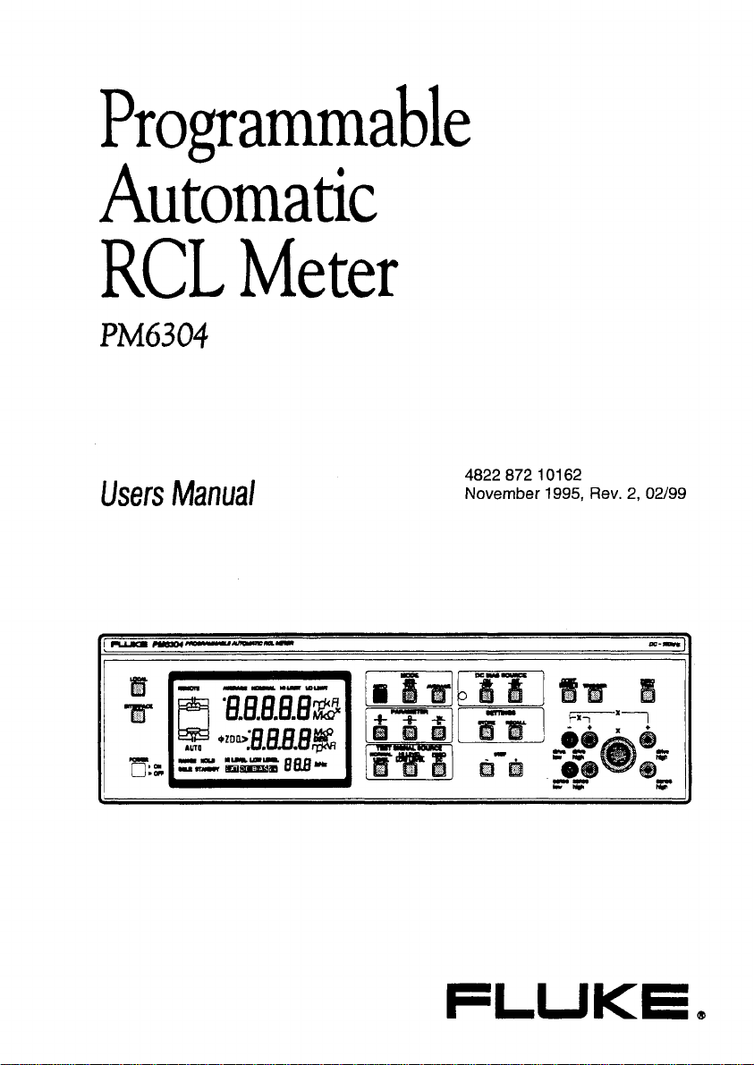
Programmable
Automatic
RCL
Users
Manual
Meter
4822 872
November 1995, Rev.
101
62
2,
02/99
Page 2
Please note
In correspondence concerning this instrument, please quote the type number
and serial number as given on the type plate.
Bitte
beachten
Bei Schriftwechsel uber dieses Gerat wird gebeten, die Typennummer und die
Geratenurnmer anzugeben. Diese befinden sich auf dem Typenschild an der
Riickseite des Gerates.
Noter s.v.p.
Dans votre correspondance et dans vos reclamations se rapportant a cet
appareil, veuillez toujours indiquer le numero de type et le numero de serie qui
sont marques sur la plaquette de caracteristiques.
lmportant
As the instrument is an electrical apparatus,
it
may be operated only by trained
personnel. Maintenance and repairs may also be carried out only by qualified personnel.
Wichtig
Da das Gerat ein eelktrisches Betriebsrnittel ist, darf die Bedienung nur durch eingewiesenes Personal erfolgen. Wartung und Reparatur dorfen nur von geschultern, fach- und sachkundigem Personal durchgefijhrt werden.
lmportant
Comme I'instrument est un equipement electrique, le service doit etre assure par
du personnel qualifie. De mhe, I'entretien et les reparations sont
a
confier aux
personnes suffisamment qualifiees.
O
Fluke Corporation. All rights reserved. Printed in Germany
All product names are trademarks of their respective companies.
Page 3
CONTENTS
Users Manual
CONTENTS
PM6304
lnstrucciones de instalacion y de seguridad
lstruzioni per la messa in funzione e norme di sicureua
lnstructies met betrekking tot de installatie en veiligheid
lnledande anvisningar och sakerhetsanvisningar
Figures
Appendix
Diagrams and Formulas
Table for Storage Register Contents
&
Limited Warranty
Declaration of Conformity
Limitation of Liability
@
a
@
@
Service Centers
Page 4

Page 5
PM6304 INSIDE THIS MANUAL
-1-
INSIDE THlS MANUAL
This USERS MANUAL contains information on all features of the PM6304 and
PM6304C instruments.
It starts with a shipment note and an initial inspection.
The manual is organized into the following chapters:
Chapter
1
Installation and Safety Instructions
This chapter should be read before unpacking, installing, and operating the
instrument. It describes grounding, power cables, and line voltage settings.
Chapter
2
Main Capabilities
This chapter describes the main features of the instrument, its functions, operation modes, measurement possibilities and its options.
Chapter
3
Getting Started
This chapter starts with general procedures and precautions necessary for
operation followed by a short functional test. It contains a description of the
display, a summary of controls and connectors on the front and rear panels, and
a description of accessories and measurement setups.
Chapter
How to Use the Instrument
4
This chapter provides the user with detailed explanations of the measurement
principle and the measurement of different components.
Chapter
5
Function Reference
This chapter contains a description of each function in alphabetical order. Each
description includes an explanation of local and remote control functions.
Page 6
-
2
-
INSIDE THIS MANUAL PM6304
Included in the shipment
The
REFERENCE
CHARACTERISTICS
PRINCIPLE OF OPERATION
BRIEF CHECKING PROCEDURE
PERFORMANCE TEST
PREVENTIVE MAINTENANCE
APPENDIX
SERVICE CENTERS
you
find an additional REFERENCE MANUAL.
MANUAL
contains:
Page 7
PM6304 CONTENTS -1-
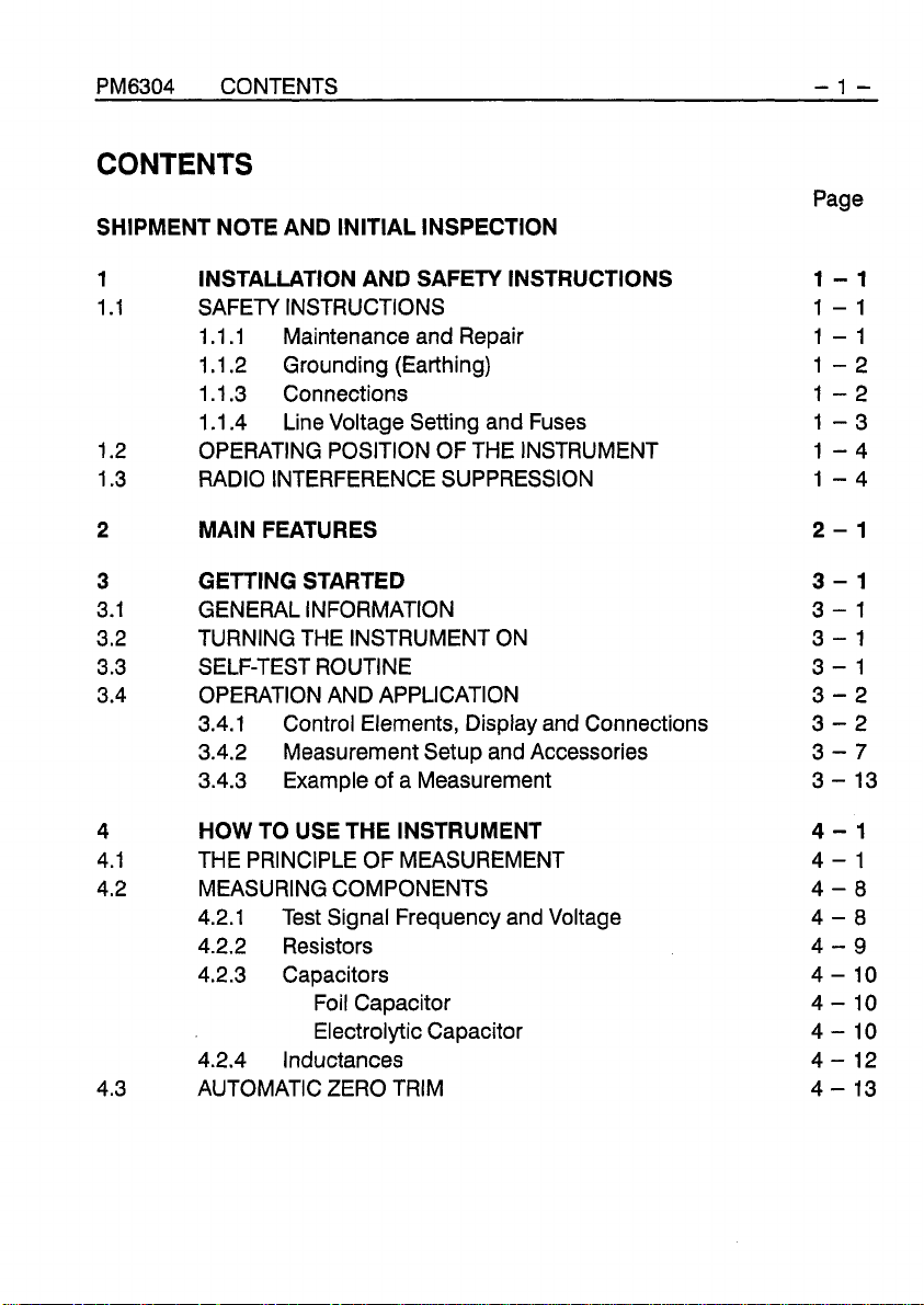
CONTENTS
Page
SHIPMENT NOTE AND INITIAL INSPECTION
1
1.1 SAFETY INSTRUCTIONS
1.2 OPERATING POSITION OF THE INSTRUMENT
1.3 RADIO INTERFERENCE SUPPRESSION
2
3
3.1 GENERAL INFORMATION
3.2 TURNING THE INSTRUMENT ON
3.3 SELF-TEST ROUTINE
3.4 OPERATION AND APPLICATION
4
4.1 THE PRINCIPLE OF MEASUREMENT
4.2 MEASURING COMPONENTS
4.3 AUTOMATIC ZERO TRIM
INSTALLATION AND SAFETY INSTRUCTIONS
1.1.1 Maintenance and Repair
.I
.2 Grounding (Earthing)
1
1.1.3 Connections
1.1.4 Line Voltage Setting and Fuses
MAIN FEATURES
GETTING STARTED
3.4.1 Control Elements, Display and Connections
3.4.2 Measurement Setup and Accessories
3.4.3 Example of a Measurement
HOW TO USE THE INSTRUMENT
4.2.1 Test Signal Frequency and Voltage
4.2.2 Resistors
4.2.3 Capacitors
Foil Capacitor
Electrolytic Capacitor
4.2.4 Inductances
Page 8
-2- CONTENTS PM6304
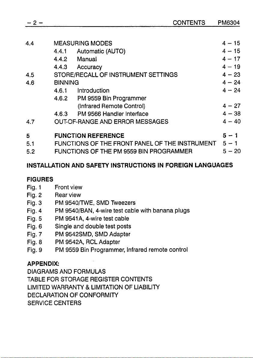
4.4 MEASURING MODES
4.4.1 Automatic (AUTO)
4.4.2 Manual
4.4.3 Accuracy
4.5
4.6 BINNING
4.7 OUT-OF-RANGE AND ERROR MESSAGES
STOREIRECALL OF INSTRUMENT SETTINGS
4.6.1 Introduction
4.6.2 PM 9559 Bin Programmer
(Infrared Remote Control)
4.6.3 PM 9566 Handler Interface
5
5.1
5.2
INSTALLATION AND SAFETY INSTRUCTIONS IN FOREIGN LANGUAGES
FIGURES
Fig.
Fig. 2 Rear view
Fig. 3
Fig. 4
Fig. 5
Fig. 6
Fig. 7 PM 9542SMD, SMD Adapter
Fig.
Fig. 9
APPENDIX:
DIAGRAMS AND FORMULAS
TABLE FOR STORAGE REGISTER CONTENTS
LIMITED WARRANTY
DECLARATION OF CONFORMITY
SERVICE CENTERS
FUNCTION REFERENCE
FUNCTIONS OF THE FRONT PANEL OF THE INSTRUMENT
FUNCTIONS OF THE PM 9559 BIN PROGRAMMER
1
Front view
PM 9540/TWE, SMD Tweezers
PM 9540/BAN, 4-wire test cable with banana plugs
PM
9541A, 4-wire test cable
Single and double test posts
PM 9542A, RCL Adapter
8
PM 9559 Bin Programmer, Infrared remote control
&
LIMITATION OF LIABILITY
5-1
-
5
-
5
1
20
Page 9
PM6304 SHIPMENT NOTE
-1-
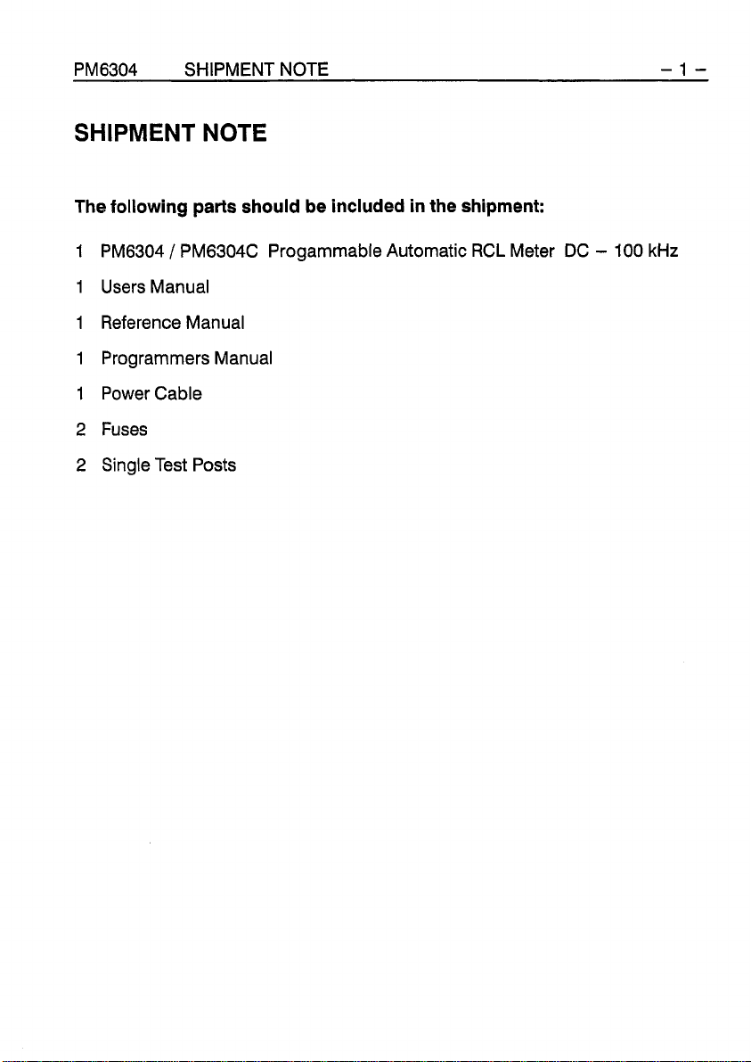
SHIPMENT
The following
1
PM6304 / PM6304C Progammable Automatic
1
Users Manual
1
Reference Manual
1
Programmers Manual
1
Power Cable
2
Fuses
2
Single Test Posts
NOTE
parts
should be included in the shipment:
RCL
Meter
DC
-
100
kHz
Page 10
- 2 -
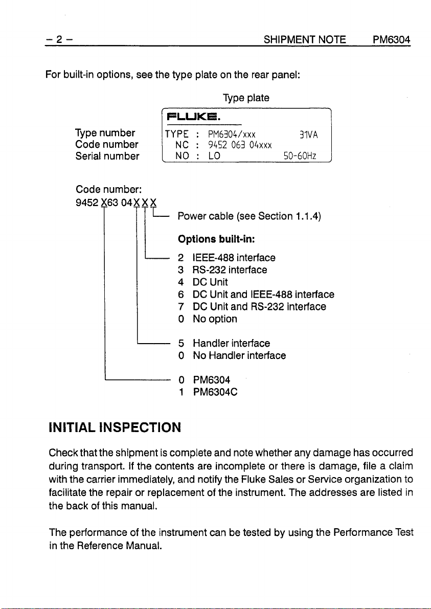
For built-in options, see the type plate on the rear panel:
Type plate
[
FLUKE.
Type number
Code number
Serial number
Code 9452 13 number: 041L
TYPE : PM6304/xxx 31VA
1
NC
:
9452 063 04xxx
NO : LO
Power cable (see Section 1.1.4)
SHIPMENT NOTE PM6304
50-60Hz
Options built-in:
2 IEEE-488 interface
3 RS-232 interface
4 DC Unit
6 DC Unit and IEEE-488 interface
7
DC Unit and RS-232 interface
0
No option
1
5 Handler interface
0 No Handler interface
INITIAL INSPECTION
Check that the shipment is complete and note whether any damage has occurred
during transport. if the contents are incomplete or there is damage, file a claim
with the carrier immediately, and notify the Fluke Sales or Service organization to
facilitate the repair or replacement of the instrument. The addresses are listed in
the back of this manual.
The performance of the instrument can be tested by using the Performance Test
in the Reference Manual.
Page 11

Chapter
INSTALLATION AND SAFETY INSTRUCTIONS
1
Page 12

Page 13
PM6304
INSTALLATION AND SAFETY INSTRUCTIONS
1-1
1
1
.I
Upon delivery from the factory the instrument complies with the required safety
regulations (see Reference Manual, Chapter
ensure safe operation, the instructions below must be followed carefully.
1.1.1
Failure and excessive stress:
If the instrument is suspected of being unsafe, remove it from operation immediately and secure it against any unintended operation. The instrument is considered to be unsafe when any of the following conditions exist:
It shows physical damage.
It does not function anymore.
It is stressed beyond the tolerable limits
(e.g., during storage and transportation).
Disassembling the Instrument:
INSTALLATION AND SAFEN INSTRUCTIONS
SAFETY INSTRUCTIONS
1).
To maintain this condition and to
Maintenance and Repair
WARNING
Calibration, maintenance, and repair of the instrument must be performed only by trained personnel who are aware of the hazards involved.
To avoid electric shock, do not remove the cover unless you are quali-
fied to do so.
Before removing the cover, disconnect the instrument from all power
sources. The capacitors in the instrument may remain charged for
several seconds after all power has been disconnected.
Page 14
1-2
1
.I
.2
Grounding (Earthing)
INSTALLATION AND SAFETY INSTRUCTIONS
PM6304
Before any other connection is made the instrument must be connected to a
protective earth conductor via the three-wire power cable.
The power plug shall be inserted only into a grounded outlet.
Do not defeat the protective action by using an extension cord without a grounded
conductor.
Do not connect a protective ground conductor into the measurement contacts
on the front panel, the four contacts of the connector to which the circuit ground
is applied, or the external contact of the connector plug.
WARNING
Any interruption of the protective ground conductor inside or outside
the instrument or disconnection of the protective ground terminal, is
likely to make the instrument dangerous. Intentional interruption is
prohibited.
1
.I
.3
Connections
The circuit ground potential is applied to four of the eight contacts of the front
panel connector and is connected to the instrument case via parallel-connected
capacitors and a resistor. The external contact of the connector is connected to
the instrument case. This avoids ac ground loops while providing good RF
grounding.
If the circuit ground potential in a measurement setup is different from the protective ground potential, make sure that the four contacts of the front panel connector
are not live.
Page 15
PM6304
1
.I
.4
INSTALLATION AND SAFETY INSTRUCTIONS
Line Voltage Setting and Fuses
1-3
Before plugging in the line cable, make sure that the instrument is set to the
correct line voltage.
WARNING
To avoid injury or death, changing fuses and modifying line cables to
local power must be done by qualified service personnel who are
aware of the hazards involved.
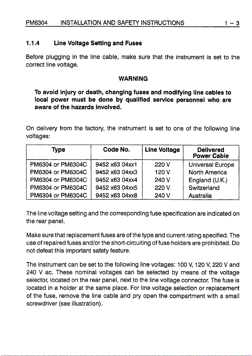
On delivery from the factory, the instrument is set to one of the following line
voltages:
Code No.
Line Voltage
Delivered
Power Cable
9452 x63 04~x1
9452 x63 04~x3
9452 x63 04~x4
9452 x63 04~x5
9452 x63 04~x8
220
120
240
220
240
V
V
V
V
V
Universal Europe
North America
England (U.K.)
Switzerland
Australia
The line voltage setting and the corresponding fuse specification are indicated on
the rear panel.
Make sure that replacement fuses are of the type and current rating specified. The
use of repaired fuses
and/or the short-circuiting of fuse holders are prohibited. Do
not defeat this important safety feature.
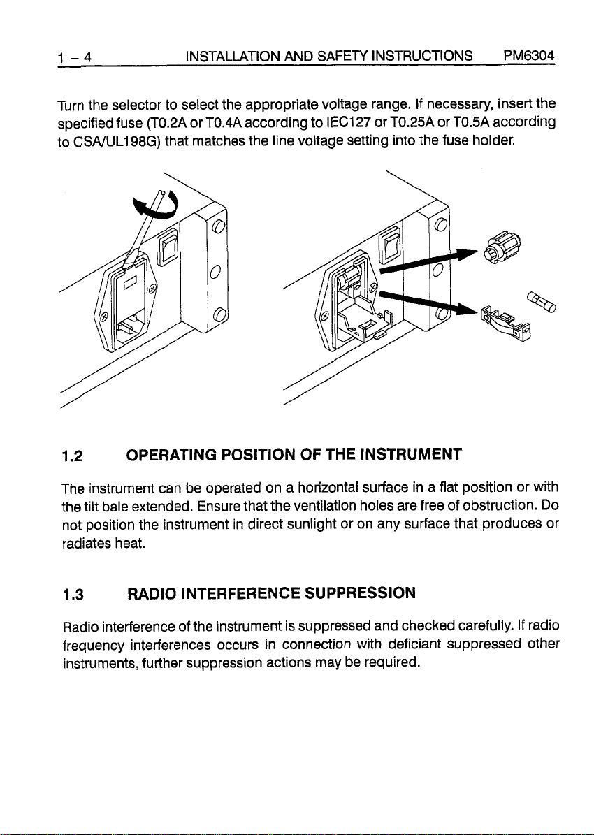
The instrument can be set to the following line voltages:
240
V ac. These nominal voltages can be selected by means of the voltage
100
V,
120
V,
220
V and
selector, located on the rear panel, next to the line voltage connector. The fuse is
located in a holder at the same place. For line voltage selection or replacement
of the fuse, remove the line cable and pry open the compartment with a small
screwdriver (see illustration).
Page 16
1-4 INSTALLATION AND
Turn the selector to select the appropriate voltage range. If necessary, insert the
specified fuse
to CSAJUL198G) that matches the line voltage setting into the fuse holder.
(T0.2A
or TOAA according to IEC127 or TOZA or T0.5A according
SAFETY
INSTRUCTIONS PM6304
1.2
The instrument can be operated on a horizontal surface in a flat position or with
the tilt bale extended. Ensure that the ventilation holes are free of obstruction. Do
not position the instrument in direct sunlight or on any surface that produces or
radiates heat.
1.3
Radio interference of the instrument is suppressed and checked carefully. If radio
frequency interferences occurs in connection with deficiant suppressed other
instruments, further suppression actions may be required.
OPERATING POSITION OF THE INSTRUMENT
RADIO INTERFERENCE SUPPRESSION
Page 17

Chapter
2
MAIN
FEATURES
Page 18

Page 19
PM6304 MAIN FEATURES 2-1
2
The
ments of resistance, capacitance, and inductance. Its basic accuracy is 0.1
The
0.05
function and autoranging feature. It allows fast and high precision measurements
and diagnostic of passive components over a wide range.
The component to be measured is connected to the instrument via front panel
posts, the PM 9541A four-wire test cable, or the PM 9542A four-terminal test
adapter. The Adapter PM
surface-mounted components are also available.
Measurements are performed using a four-wire system.
The test frequency is selectable in the range from 50 Hz to 100 kHz.
Three test voltages are available:
The measurement result, the numerical value, dimension, and the equivalent
circuit symbol, are all displayed on the large five-digit liquid-crystal display (LCD),
which is updated at a rate of approximately two measurements per second.
A
microprocessor controls the measurement process, computes the measure-
ment value, and transfers the result to the display.
MAIN
PM6304 Programmable Automatic RCL Meter
PM6304C Programmable Automatic RCL Meter
%
at test signal frequencies up to 2 kHz. The instrument provides an auto-
FEATURES
9542SMD or the PM 9540/TWE SMD Tweezers for
is used for precise measure-
2
V, 1 V, and 50 mV rms.
has a higher accuracy of
%.
In the AUTO mode the dominant and the secondary parameter, either
of the component under test is automatically selected for display.
For example, for an inductance with a quality factor
instrument indicates the measurement value of the series inductance and the
series resistance and as the equivalent-circuit symbol, the series connection of
an inductance and a resistance.
In addition to AUTO mode, the following modes can be selected:
series respectively parallel components
impedance
phase angle
quality factor
component voltage V,, component current I,
Z
Q
Q,
dissipation factor D
Q
between 1 and 1000, the
R,
C,
or L
Page 20
2-2 MAIN FEATURES PM6304
(2
V
An internal DC BlAS voltage
dc) can be added to the measurement voltage
for electrolytic capacitors.
An external DC BlAS voltage can also be selected, up to 40
V
dc.
DC resistance measurements without an ac test signal can be made by using the
optional PM 9565 DC Unit.
The instrument can be programmed and can transfer its measurement data via
the optional PM 9548 lnterface for IEEE-488, or via the PM 9549 lnterface for
RS-232. Ten measurements per second are also possible. The RS-232 lnterface
also allows output of measurement results directly to a printer with no controller
needed.
For sorting and binning of components, the optional infrared remote control, the
PM 9559 Bin Programmer, and the PM 9566 Handler lnterface are available.
Nine complete instrument settings can be stored and recalled for fast and convenient setup.
Page 21

Chapter
GETTING STARTED
3
Page 22

Page 23
PM6304 GETTING STARTED 3-1
GETTING STARTED
3.1
This section outlines the procedure and precautions necessary for operation. It
identifies and briefly describes the functions of the front and rear panel controls
and the display.
3.2
After the instrument has been connected to the line voltage in accordance with
Section
to
ON.
The specifications given in the Reference Manual, Chapter
instrument is installed in accordance with the instructions in Chapter
manual and a warm-up period of
After turning the power off, wait at least
allows all power to completely discharge and the instrument to reset.
3.3
After power on, the instrument performs a self-test of the PROM, processor RAM,
and external RAM. After this, the software version is indicated in the upper line of
the display for approximately
shown for approximately
instrument state before power off.
GENERAL INFORMATION
TURNING THE INSTRUMENT ON
1.1.4, it can be turned on by setting the
5
minutes is allowed.
5
seconds before turning it on again. This
SELF-TEST ROUTINE
1
second. All segments of the display field are
2
seconds, and the instrument automatically recalls its
POWER
switch on the front panel
1,
are valid when the
1
of this
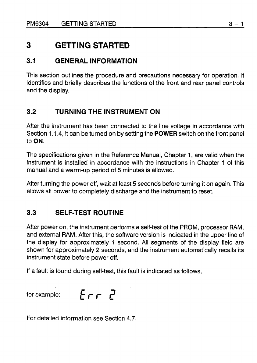
If a fault is found during self-test, this fault is indicated as follows,
-
for example:
For detailed information see Section 4.7.
r,TT
C
r,
J
Page 24
3-2 GETTING STARTED PM6304
3.4
3.4.1
3.4.1.1
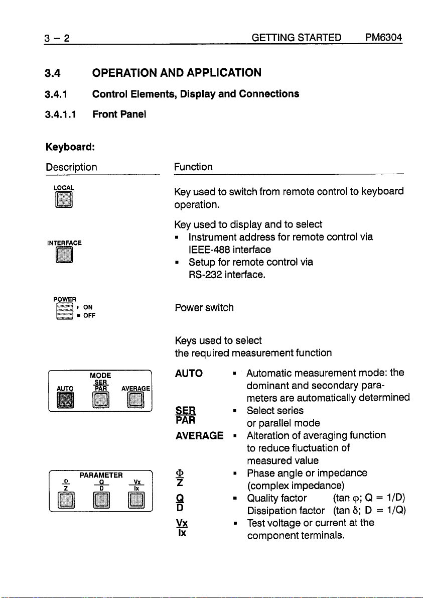
OPERATION AND APPLICATION
Control Elements, Display and Connections
Front Panel
Keyboard:
Descri~tion
LOCAL
INTERFACE
0
POWER
;
:;F
Function
Key used to switch from remote control to keyboard
operation.
Key used to display and to select
Instrument address for remote control via
IEEE-488 interface
Setup for remote control via
RS-232 interface.
Power switch
Keys used to select
the required measurement function
f
MODE
1
AUTO
Automatic measurement mode: the
dominant and secondary para-
meters are automatically determined
SEE
Select series
PAR or parallel mode
AVERAGE Alteration of averaging function
to reduce fluctuation of
measured value
PARAMETER
0
-
L
-
vx
-
Z
9
D
!b!
Phase angle or impedance
(complex impedance)
Quality factor (tan
Dissipation factor (tan
$;
6;
Q
D
Test voltage or current at the
=
=
1
ID)
1
IQ)
0
Ix component terminals.
Page 25
PM6304 GETTING STARTED 3
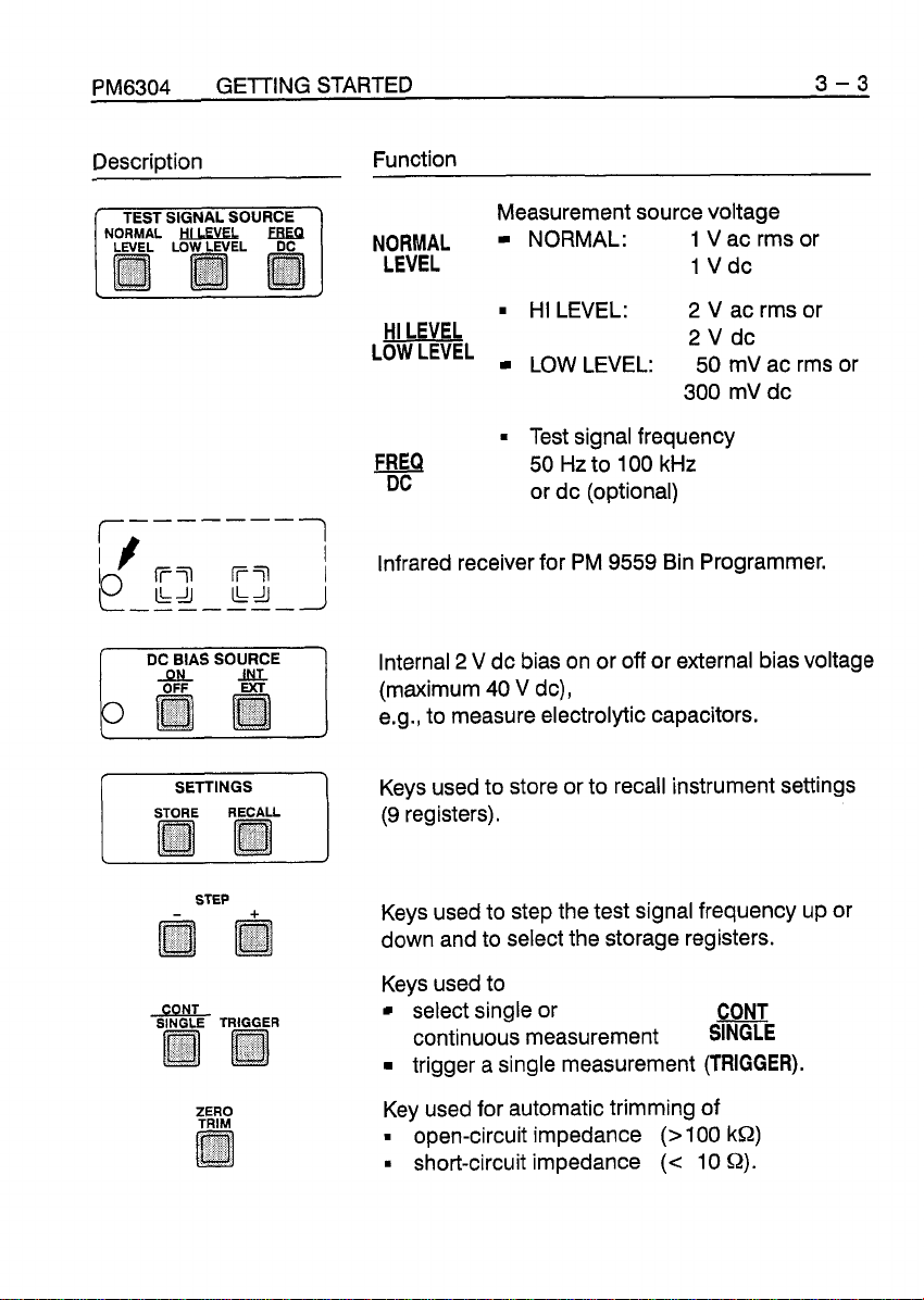
Description Function
SIGNAL
SOURCE
NORMAL
Measurement source voltage
NORMAL:
1
V
ac rms or
LEVEL 1 Vdc
-
3
f
DC
BIAS SOURCE
SETTINGS
STEP
HI LEVEL
LEVEL
HI LEVEL:
~
-
LOW LEVEL: 50 mV ac rms or
2
2
V
V
ac rms or
dc
Test signal frequency
FREa
DC
50 Hz to 100 kHz
or dc (optional)
Infrared receiver for PM 9559 Bin Programmer.
Internal
(maximum 40
2
V
dc bias on or off or external bias voltage
V
dc),
e.g., to measure electrolytic capacitors.
Keys used to store or to recall instrument settings
'I
(9 registers).
I
Keys used to step the test signal frequency
up
or
down and to select the storage registers.
Keys used to
select single or CONT
continuous measurement
S~E
trigger a single measurement (TRIGGER).
Key used for automatic trimming of
open-circuit impedance
short-circuit impedance
(>
(c
100
10
k!2)
Q).
Page 26
3 - 4 GETTING STARTED PM6304
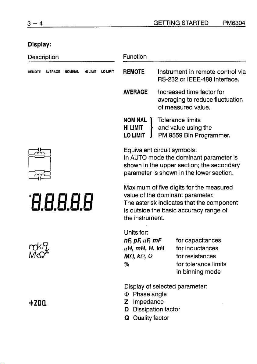
Display:
Description Function
REMOTE
AVERAGE
NOMINAL
HILIMIT LOLIMIT
REMOTE
Instrument in remote control via
RS-232 or IEEE-488 Interface.
AVERAGE
Increased time factor for
averaging to reduce fluctuation
of measured value.
Tolerance limits
and value using the
PM
9559 Bin Programmer.
Equivalent circuit symbols:
In AUTO mode the dominant parameter is
shown in the upper section; the secondary
parameter is shown in the lower section.
Maximum of five digits for the measured
value of the dominant parameter.
The asterisk indicates that the component
is outside the basic accuracy range of
the instrument.
Units for:
nF,
pF,
pe
pH, mH, H,
MQ,
kQ,
Q
%
mF
kH
for capacitances
for inductances
for resistances
for tolerance limits
in binning mode
Display of selected parameter:
@
Phaseangle
Z
Impedance
D Dissipation factor
Q
Quality factor
Page 27
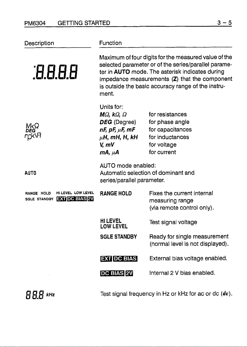
PM6304
Description Function
:BmEI.EI.EI
AUTO
GETTING STARTED
Maximum of four digits for the measured value of the
selected parameter or of the
ter in
impedance measurements
is outside the basic accuracy range of the instru-
ment.
Units for:
Ma, kQ,
DEG
n6
pH, mH, H, kH
v;
mV
mA,
AUTO mode enabled:
Automatic selection of dominant and
series/parallel parameter.
AUTO
(Degree) for phase angle
p6
,uF,
series/parallel parame-
mode. The asterisk indicates during
(2)
that the component
a
mF
for resistances
for capacitances
for inductances
for voltage
for current
3-5
RANGE
HOLD
SGLE STANDBY
HI
LEVEL
LOW
LEVEL
RANGE
mmm
HI LEVEL
LOW LEVEL
SGLE STANDBY
mEipl
Test signal frequency in Hz or kHz for ac or dc
HOLD
Fixes the current internal
measuring range
(via remote control only).
Test signal voltage
Ready for single measurement
(normal level is not displayed).
External bias voltage enabled.
Internal
2
V
bias enabled.
(dc).
Page 28
3-6 GETTING STARTED PM6304
Description Function
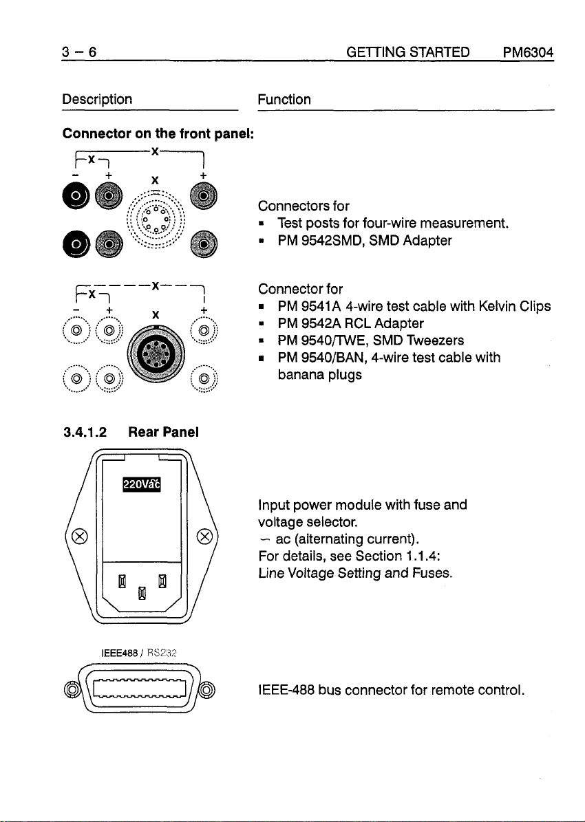
Connector on the front panel:
rx1
+
X
+
Connectors for
=
Test posts for four-wire measurement.
PM 9542SMD, SMD Adapter
Fx7---"--7
-
+
3.4.1.2
Rear Panel
Connector for
PM 9541A 4-wire test cable with Kelvin Clips
PM 9542A RCL Adapter
=
PM 9540/lWE, SMD Tweezers
PM 9540/BAN, 4-wire test cable with
banana plugs
Input power module with fuse and
voltage selector.
-
ac (alternating current).
For details, see Section 1.1.4:
Line Voltage Setting and Fuses.
@Ezzz$
IEEE-488 bus connector for remote control.
Page 29
PM6304 GElllNG STARTED 3-7
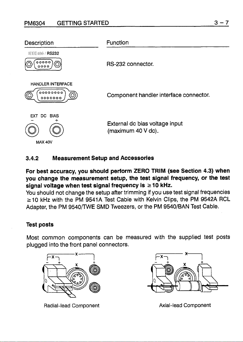
Description Function
RS-232 connector.
HANDLER INTERFACE
Component handler interface connector.
EXT
DC
-
BIAS
+
External dc bias voltage input
MAX
(maximum 40
40V
V
dc).
3.4.2
For best accuracy, you should perform ZERO TRIM (see Section
Measurement Setup and Accessories
4.3)
when
you change the measurement setup, the test signal frequency, or the test
signal voltage when test signal frequency is
r
10
kHz.
You should not change the setup after trimming if you use test signal frequencies
r
10
kHz
with the PM 9541A Test Cable with Kelvin Clips, the PM 9542A RCL
Adapter, the PM 9540m/VE SMD Tweezers, or the PM 9540/BAN Test Cable.
Test posts
Most common components can be measured with the supplied test posts
plugged into the front panel connectors.
Radial-lead Component Axial-lead Component
Page 30
3 - 8 GETTING STARTED
PM6304
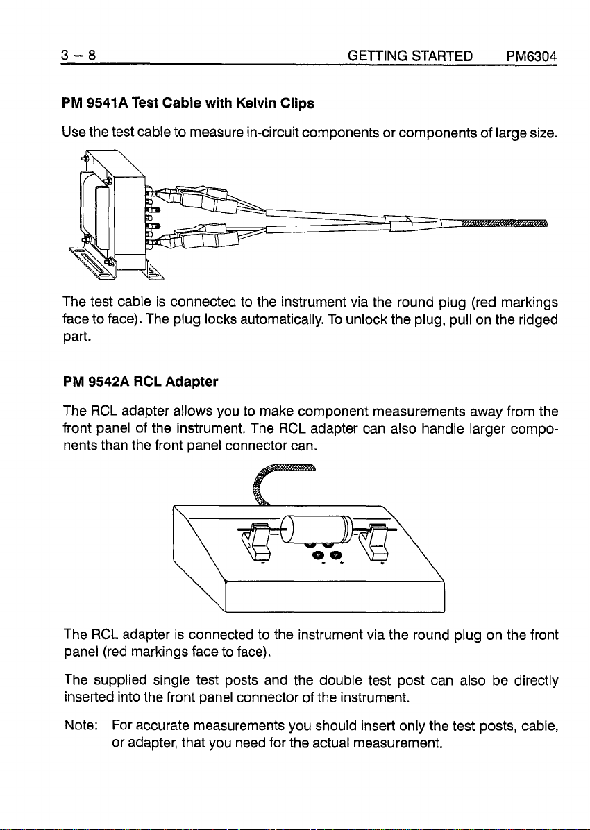
PM 9541A Test Cable with Kelvin Clips
Use the test cable to measure in-circuit components or components of large size.
The test cable is connected to the instrument via the round plug (red markings
face to face). The plug locks automatically. To unlock the plug, pull on the ridged
part.
PM 9542A RCL Adapter
The RCL adapter allows you to make component measurements away from the
front panel of the instrument. The RCL adapter can also handle larger compo-
nents than the front panel connector can.
The RCL adapter is connected to the instrument via the round plug on the front
panel (red markings face to face).
The supplied single test posts and the double test post can also be directly
inserted into the front panel connector of the instrument.
Note: For accurate measurements you should insert only the test posts, cable,
or adapter, that you need for the actual measurement.
Page 31

PM6304 GETTING STARTED 3-9
SMD
Adapter
PM 9542SMD
The SMD adapter can be used to measure SMD components with a length of 2 to
10 mm, depth
>1
mm, height >0.5 mm, or a diameter
>I
mm.
For easy and quick insertion and removal of components, insert the SMD adapter
into the PM 9542 RCL adapter.
You can also insert the SMD adapter directly into the front panel connector of the
instrument. To ease insertion of components, set the instrument in a sloping posi-
tion (handle folded down)
When you use the SMD adapter to measure very small capacitances especially
below 100 pF, you must take into account the alteration of the stray fixture capaci-
tances, depending on the separation of the contacts.
Page 32

3
-
10
Fixture Capacitance (pF)
4
1.4
--
GETTING STARTED
PM6304
Additional capacitance alter
ZERO
TRIM depending on
contact opening of the SMD adapter.
0
-1
--
PM
9540llWE
SMD
Tweezers
contact opening width
(rnm)
Use the SMD Tweezers to measure single SMD components or in-circuit SMD
components.
The SMD Tweezers are connected to the instrument via the round plug on the
front panel (red marking face to face).
Page 33

PM6304 GETTING STARTED 3-11
For open-circuit trimming when you are measuring small capacitances, set the
opening of the tweezers to the size of the component.
The two-wire measuring technique and the pressure applied by the tips of the
tweezers can cause a measuring error in addition to the basic error of the RCL
GI).
Meter, due to the additional serial resistance (typical 0.02
or contaminants on the tips of the tweezers can also affect measurements. The
tips may be periodically cleaned with alcohol and a non-abrasive cloth.
The presence of dirt
PM 9540/BAN
Use the test cable if you need banana plugs for your own special applications.
The test cable is connected to the instrument via the round plug on the front panel
(red marking face to face).
When you perform ZERO TRIM short-circuit DRIVE+ with SENSE+ and DRIVEwith SENSE- for the open-circuit trimming. Short-circuit all four plugs for the
short-circuit trimming.
Test Cable with Banana
Plugs
Page 34

3-
12
GElTING STARTED
PM6304
Two-Wire Measurements
You can measure components with two test leads in two-wire mode by using the
plus and minus connectors. For this, it is necessary to short-circuit the drive and
sense lines at the instrument. To reduce stray capacitances and interferences,
use short leads.
You also can use the eight-pole round connector.
test leads test leads
or
drive - sense
+
The technical specifications given in Chapter 1 of the REFERENCE MANUAL are
valid for four-wire measurements. Four-wire measurements are particularly important for high impedance components at high test signal frequencies and for low
impedance components.
Page 35

PM6304 GETTING STARTED 3- 13
3.4.3
Example of a Measurement
WARNING
Before turning the instrument on, ensure that it has been installed in
accordance with the instruction in Chapter
1.
Immediately after power on a self-test routine is performed. Then the instrument
automatically recalls measurement settings prior to the last power off.
(see Section 3.3).
FX1
Insert the test posts supplied into
the connector on the front panel
(Logos face to face).
If the display shows
press the
EBEQ
DC
key.
dr
,
Select an appropriate measurement
1
frequency, for example,
kHz.
Press the green AUTO key.
The display shows:
Press the ZERO TRIM key for 2 seconds.
STEP
AUTO
Page 36

3
-
14 GElTING STARTED PM6304
For open-circuit trimming
the display shows:
For short-circuit trimming short circuit
the test posts with a short wire or
similar object and press the ZERO TRlM key;
the display shows:
If the ZERO TRlM operation is
unsuccessful, the
Refer to Section 4.7.
If the ZERO TRlM operation was
successful, the diplay shows:
Insert a known component
into the test posts,
e.g., a
1
kS2
diplay shows:
resistor.
bUSY
Cct
The display shows:
The test is finished.
See Chapter
information about measurement
of components and
measurement principles.
4 for detailed
AUTO
[t
kHz
Page 37

Chapter
HOW TO USE THE INSTRUMENT
4
Page 38

Page 39

PM6304 HOW TO USE THE INSTRUMENT 4-1
4 HOW TO USE THE INSTRUMENT
4.1
THE PRINCIPLE
OF
MEASUREMENT
The component measurement is based on the current and voltage technique. The
component voltage and the component current are measured and converted into
binary values. From these values the CPU calculates the electrical parameters of
the component. According to the front panel parameter selection different para-
meters are displayed. Via AUTO mode or by pressing the SERIPAR key when
AUTO mode was selected, the dominant and secondary parameters (resistance,
capacitance, or inductance) are displayed. In addition manually selected para-
meter can be displayed
(Q,
D,
2,
@,
V,, or
I,).
Each measurement cycle lasts approximately 0.5 seconds. For AC measurements one cycle consists of seven single measurements, the results of which are
stored and arithmetically evaluated. Finally the result is transferred to the display.
The seven single measurements are as follows:
1.
Voltage Measurement:
O0
and internal gain factor setting
2.
3.
Gain factor
4.
Reference Measurement:
5.
Current Measurement:
6.
Current Measurement:
7.
Reference Measurement:
>1
Voltage Measurement:
Reference Measurement:
Gain factor
90°
O0
90°
O0
Current Measurement:
Current Measurement:
ReferenceMeasurement:
Reference Measurement:
90°
00
=
1
O0
90°
O0
90°
Page 40

4-2 HOW TO USE THE INSTRUMENT PM6304
The seven measured values are stored at the end of the single measurements.
The microprocessor uses the measured values to calculate the equivalent series
resistance Rs, the equivalent series reactance Xs, and the quality factor
Q = XsIRs of the component. In AUTO mode the microprocessor determines the
dominant and secondary parameter, calculates its value, and displays it together
with the equivalent circuit symbol. If one of the other parameters is manually
selected, this parameter is calculated and displayed. After that
measurement cycle starts with the seven single measurements.
The display shows:
Inn-
r
u.u
The following phase diagrams and formulas show the mathematic basics for internal calculation of the component value.
b
I I-l
r
the next
I=
V2A
Vqr------
vp Ip v1
In the diagram the phase relation between I and V happens to be a lossy inductance.
In each measurement cycle, the following components are determined:
V: voltage
I: current
V1, V2: 0"-voltage, 90"-voltage
I
The phase angle between
The phase angle between I and V1 is
VP, vq, IP, Iq.
and V is
4.
a.
Page 41

PM6304
The series resistance and reactance are calculated from these components.
HOW
TO
USE THE INSTRUMENT 4-3
The following equivalent circuit is valid:
Quality factor:
Dissipation factor:
The magnitude of Q and the sign of Xs determine which parameter of the component is dominant.
The formulas for the various parameters are as follows:
Q=-
lXs'
see equation (3)
Rs
=
tan@ = 1
Q
D = tan6 = 1/Q
Xs positive
Xs negative
/D
=
=
~xt
=
-
I
xs
(3)
Rs
lRs'
=
-
inductive
capacitive
Xs
(4)
z=mTG
Cp
=
w(1
+
1
1/Q2)1XsI
ifXs
ifXs
<
>
0
0
Rs see equation
(1)
Impedance
Admittance
Z = R + jX
Y
=
1
/Z
<
ifXs
ifXs > 0
0
Page 42

4-4 HOW TO USE THE INSTRUMENT PM6304
Example:
By using the seven measurements, the instrument has calculated Rs and Xs in
2,
accordance with formulas 1 and
for example,
From this the instrument calculated:
The instrument displays the corresponding equivalent circuit symbol with the
dominant and the secondary parameter, according to the criteria of the Auto
Mode Decision Diagram (see Section 4.4.1); in this case, as Xs is negative and
1
<Q<
1000:
The display shows:
The calculation of the dominant parameter Cp was done according to the fol-
lowing formula:
Cp
=
1
2n
x
1 kHz (1 + 1 /4.9542) x 15.199
kS2
=
10.061 nF
The maximum display is five digits 21 digit tolerance.
Page 43

PM6304
HOW
TO USE
THE
INSTRUMENT 4-5
Calculation of the other selectable parameters are performed as follows:
1
D=-=--
Q
4.954
-
0.202
Rs
(calculated by the instrument according to formula 1)
Q,
:
The instrument calculates
tan
and gets
lXsl 15.199
Q,
=
-
Rs 3.068
Q,
=
from an internal tangent table similar to a calculator
=
(1
+
4.9542) x 3.068
kR
=
4.954
kSZ
kS2
=
78.36
kR
Q
=
-
78.6 DEG
Page 44

4-6 HOW TO USE THE INSTRUMENT PM6304
For accurate measurement, you should select an appropriate test signal frequen-
cy; see Section 4.2.
If you measure the same component mentioned in the preceding example, with
a
test signal frequency that is too low, the resistive part of the capacitive component dominates.
So the instrument determines a resistor as the dominant parameter.
Example:
Test signal frequency 100 Hz
The display shows:
The instrument determined:
Rs
=
63.248
XS = -31.680
kS2
kQ
and calculated:
Qe
Because
1, the display shows a resistor as the dominant parameter.
Page 45

PM6304
HOW
TO USE THE INSTRUMENT
4-7
Calculation of the other parameter is performed
1
D
=
-
=
2.00
Q
Rp = (1
Cp
Rs
Cs
tan
iP
+
Q2)
x
RS = 79.123 kQ
=
w(l
=
63.248 kQ (calculated according to formula 1)
=
-
wlXsl
iP
=
=
-
+
1
-
lXs
Rs
26.6
1
1
/Q2)
=
50.23 nF
'
=
DEG
1XsI
0.501
=
10.08 nF
by
the same formulas:
If you are interested in mathematics, the appendix of this guide shows the phasor
diagrams and formulas for the various components.
Page 46

4-8 HOW TO USE THE INSTRUMENT PM6304
4.2
4.2.1
Resistors, inductors, and capacitors are not ideal electrical components. They all
have secondary effects that limit their performance. Understanding the effects is
important in understanding the results displayed on the RCL meter. For example,
a resistor has shunt capacitance and lead inductance. Inductors have shunt
capacitance and resistance in their windings.
The differing reaction of these components, which depends on the frequency and
test signal voltage, requires methods of measurement adapted to each situation.
To this end, the PM6304
Resolution: 50, 60, 100, 120, 200, 300, 400
The analog-to-digital converter (ADC), used for digitizing the measured values,
is basically insensitive to hum interfered into the measurement setup. Hum inter-
ference may degrade measurement accuracy using test frequencies of 60 Hz or
120 Hz at 50 Hz AC power or 50 Hz test frequency at 60 Hz AC power.
The following can be selected as the test signal voltage:
AC
voltage:
2 V, 400 Q internal resistance
1 V, 100 Q internal resistance
50 mV, 100 Q internal resistance 300 mV, 100
MEASURING COMPONENTS
Test Signal Frequency and Voltage
/
PM6304C has afrequency range from 50 Hz to 100 kHz.
Hz
DC
to 19.9 kHz, 20 kHz, 100 kHz
voltage (option):
2 V, 400
V,
1
D
internal resistance
100 Q internal resistance
D
internal resistance
An internal
added to the AC voltage signal. The external voltage must be free of hums, partic-
ularly if test signal frequency is 50 Hz or 60 Hz (line frequencies).
If you measure components with
with an impedance >50 Q, perform open-circuit trimming with bias voltage
applied.
A
that it can cause injury if it is accidentally discharged. Verify that polarized capacitors are installed with the correct polarity before applying
a bias voltage.
2
V dc bias voltage or an external bias of maximum 40 V dc can be
Z
>
10 kQ and if you use an external bias source
WARNING
40
volt external bias can charge a capacitor to a high enough voltage
Page 47

PM6304 HOW
TO
USE THE INSTRUMENT
4-9
4.2.2
In principle in addition to its purely resistive component, a resistor has capacitive
and inductive components.
R
=
Ls
=
Cp
=
In the case of wire-wound resistors, C and
In the case of film resistors, these values are considerably smaller.
With low-valued resistors
With high-valued resistors
Resistors
DC resistance.
Inductance of any windinglcoiling and of the components leads.
Shunt capacitance across the resistive component.
L
are relatively high due to the winding.
(<I
kQ),
the series inductive component dominates.
(>I
kQ),
C predominates.
The effect of C and
Measurement Conditions:
Select a low test signal frequency, i.e., 1 kHz or measure with DC voltage (option).
In the case of resistors in the megohm range, the instrument might recognize the
shunt capacitor as the dominant component if the measurement frequency is too
high.
L
limits the high frequency performance of the component.
Page 48

4
-
10
HOW
TO USE THE INSTRUMENT PM6304
4.2.3
Capacitors
Several components, which depend on the type of capacitor, determine the electrical characteristics of a capacitor.
Foil Capacitor:
L
=
lnductance of the lead wires, the bonding and the winding
(mainly in the nH area).
R1
=
R2
Rp
C
Resistance of the bonding
=
Resistance of the foils, which increases as frequency increases.
=
Dissipation in dielectric, which can be ignored as frequency increases.
=
Capacitance.
(5
to
10
ohms in unfavorable cases).
Electrolytic Capacitors:
With AC voltage
L
ESR
C
=
lnductance of the connections and of the winding.
=
Equivalent series resistance:
Resistance of the electrolytes, the dielectric, DC resistance
of the mechanical structure. The ESR depends on the frequency.
=
Overall capacitance.
Page 49

PM6304 HOW TO USE
With DC voltage
=
C
RlsoL
Electrolytic capacitors operate at lower frequencies (usually
Measurement Conditions:
The frequency for the test signal should not be selected too high as otherwise a
capacitance that is too high is measured when the resonant
approached.
Overall capacitance.
=
Insulating resistance, it determines the leakage current of the component.
THE
INSTRUMENT 4-11
c
10 kHz).
frequency is
f,
=
self-resonant frequency
If the frequency is too low, the ohmic and inductive components falsify the result.
A
test frequency lower than f,/30 should be taken as the approximate value.
For example:
Typical self-resonant frequency for a 100 yF capacitor is 50 kHz; select test signal
frequency less than 1.6 kHz.
Electrolytic capacitors used for smoothing in power supplies should be measured
at their operating frequency (1 00
In order to determine the real dissipation components, a high test frequency is
selected for the serial losses and a low one for the parallel losses.
Use DC voltage for measuring the insulating resistance.
Hz
or 120
Hz).
Page 50

4
-
12
HOW
TO
USE THE INSTRUMENT PM6304
4.2.4
Coil with iron core
Rs
=
RE
=
Cp
=
L
=
Measurement Conditions:
As in the case of the capacitor, the test frequency (fTEST) should lie far below
the self-resonant frequency (fo). The fo frequency can be very low because of
the relatively high capacitance of the winding.
Inductances
DC resistance of the copper winding
Core loss
Capacitance of the winding
Inductance
=
1
-
2n
JLC
f,
f,
=
self-resonant frequency
Approximate value: fTEsT = f,/30
It is advisable to measure the coil close to its operating frequency if the reaction
of the coil under operating conditions is to be determined.
Avoltage level that is not too high must be selected for coils because of the saturation effect caused by the iron core. For this purpose, the PM6304 offers a voltage
50
reduced to
Use DC voltage to measure the resistance of the winding.
mV.
Page 51

PM6304 HOW TO USE THE INSTRUMENT
4-
13
4.3
When pressing the
AUTOMATIC ZERO TRIM
ZERO TRlM
key for approximately 2 seconds the instrument
performs an impedance measurement of the measurement setup and stores the
value determined. The display shows
value will be taken into consideration.
PASS.
To ensure best measuring accuracy you
For all further measurements this
should perform ZERO TRlM when you change the measurement setup, the
test signal frequency, or the test signal voltage when the test signal
1
10
frequency is
If you press the
of <10
Q
or >I00 kQ, the value of the component will be taken into consider-
kHz.
ZERO TRlM
key with a component connected with an impedance
ation. At open or short-circuited contacts of the measurement setup the instru-
ment now indicates a negative resistance value, for instance, or an inductance
in case of a connected capacitance (or a capacitor in case of a an inductance.)
Please perform ZERO TRlM once again without any component connected in order to obtain correct values.
The TRIM data are stored in a memory and will persist even if the instrument is
switched off.
Note: If you use the test cable with PM
Adapter, or the PM
9540TTWE, SMD Tweezer for test signal frequencies
9541A Kelvin Clips, the PM 9542A RCL
210 kHz, you should not change the setup after trimming.
To avoid measurement errors, do not touch the contacts during measuring.
Short-circuit Trimming
For measuring low impedances, below 100 Q in particular, please short-circuit
the contacts of the measurement setup and press the
bUSY
and
imately 2 seconds. The display shows
Sct
ZERO TRlM
(short-circuit). The instru-
key for approx-
ment now performs a measurement and stores the value determined, which is the
short circuit impedance. The display shows
PASS.
For all further measurements
this value is taken into consideration, including the line and contact impedances.
If during short circuit trimming the measured impedance is >10
Q,
FAIL
will be
displayed.
Page 52

4 - 14 HOW TO USE THE INSTRUMENT PM6304
Open-Circuit Trimming
When you measure low capacitances with high test signal frequency the opencircuit impedance of the measurement setup may affect the result. Remove any
and
ZERO
Oct
connected component and press the
conds. The display shows
a measurement considering the value determined, which is the open-circuit im-
pedance, for all following measurements. The display shows
If the impedance measured during open-circuit trimming is c 100 kS2, the diplsay
shows
For the ZERO TRIM the contacts DRIVE+ and SENSE+ as well as DRIVE- and
SENSE- should be connected. As far as the adapters available from Fluke are
concerned, this is normally ensured automatically, except for the PM 9540lBAN
cable and for the PM 9542SMD SMD Adapter.
If you use the PM 9540lBAN cable in your own special application short-circuit
DRIVE+ with SENSE+ and DRIVE- with SENSE- for the open-circuit trimming.
Short-circuit all four plugs for the short-circuit trimming.
As far as the SMD Adapter is concerned the contacts are insulated from each
other. The contacts are only closed when a component is inserted.
FAIL.
bUSY
TRIM
key for approximately 2 se-
(open-circuit). The instrument performs
PASS.
Drive- Drive+
m(=e
Contacts of the PM 9542SMD, SMD Adapter
Sense- Sense+
Page 53

PM6304 HOW TO USE THE INSTRUMENT 4- 15
To perform ZERO TRIM at an open adapter with the DRIVEISENSE contacts connected, the SMD Adapter is equipped with SMD components with an impedance
-.
m.
of Z
trimming you can use one of the attached components with an impedance of
Z
+
take into account this value if you measure low impedances.
If you need spare sets you can order them via your Service Organization with the
following number: 5322 31 0 32275.
Please use this component for open-circuit trimming. For short-circuit
0
Q. These components have a real resistance of typical 4 mQ. You should
,
---
black
blue
'
white
blue
4.4
After power on, the instrument automatically recalls the mode that was set before
power off.
Select a suitable measurement setup.
Select the matching test signal frequency and voltage
(refer to Sections 3.4.2 and 4.2).
Execute ZERO
Insert the component.
Galvanic nonconducting components, e.g., electrolytic capacitors, should be
measured with the internal bias voltage activated. To do this
Press the
The display shows
4.4.1
In most cases, you will be interested in the dominant parameter of the component.
This is automatically determined and displayed in the AUTO mode. Press the
green
in the upper line, the value of the secondary parameter in the lower line, and the
appropriate equivalent circuit symbol.
MEASURING MODES
TRIM if necessary.
DC
BIAS
ONIOFF
Automatic
AUTO
key. The display showsAUT0, the value of the dominant parameter
(AUTO)
key.
a.
Page 54

4-
16
HOW TO USE THE INSTRUMENT PM6304
Function and Key Operation Display
I-'
AUTO
The decision criterion for selecting the dominant parameter is
to Section
4.1.
The values Q and D not only depend on the component but also
on the test signal frequency used.
Reactance
D
=
1000
Q = 0.001
cl+R
Resistance
D
=
1000
Q
=
D
=
1.
Refer
AUTO MODE DECISION DIAGRAM
Page 55

PM6304
HOW
TO USE
THE
INSTRUMENT 4-
17
4.4.2
Manual
If you want to determine a parameter that differs from the one automatically calcu-
lated by the instrument, press the appropriate function key:
Function and Key Operation Display
1
n
1.U
kHz
Series or parallel parameter
tn
1.U
kHz
Impedance
Phase angle
Page 56

4-
18
Function and Key Operation Display
Dissipation factor
Quality factor
HOW TO USE THE
INSTRUMENT
PM6304
rnn
3.u
w
I
Current measured
Voltage measured
A
Current or voltage is displayed for approximately 3 seconds. The instrument
then returns automatically to the parameter you selected beforehand.
The values displayed for the selected parameter are calculated by the instrument.
They are based on the values measured for the series reactance and the series
resistance (refer to Section
A
A
4.1).
Page 57

PM6304
HOW TO USE THE INSTRUMENT
4-
19
4.4.3
Accuracy
The following diagrams show the measuring range and accuracy of the instru-
ment as a function of test signal frequency and voltage.
I
I
z
g
$
zz
L.
$2
,&
55:s
I
E*6&jrh
zz
--
zz
LL.
$C
ILa.cDI~
zz
1
SLL.
zz
r%
zz
lL
5:
N
ST
Page 58

Page 59

..I
R
'0'
100M
1 OM
1 M
look
10k
Ik
100
10
1
100m
1
Om
lrn
n
I-
1
OkH
1 kH
1
OOH
0.0lpF
1
OH
0.lpF
1H
1
PF
1
OOmH
1
OpF
1
OmH
100pF
1mH
1 nF
lOOuH
lOnF
1
OuH
1
OOnF
1
uH
1
UF
1
OOnH
1
OuF
1 OnH
1
OOuF
1 nH
1
mF
I
I
I
I I I
--..
1
OmF
Accuracy
with
50
mV (LOW LEVEL)
Page 60

Page 61

PM6304 HOW TO USE THE INSTRUMENT 4
-
23
4.5
Nine complete instrument settings including trim data can be stored in memory
registers
ries are buffered by battery so that the data are retained even after the instrument
is turned off.
After power on, the instrument runs through its start routine, and then goes to the
mode that was last set.
Store
Data are stored by pressing the STORE key. The display shows
from
are to be stored can now be selected by using the
values are not stored.
Pressing STORE once again saves the settings under the register number
selected. Any values that may exist there already are overwritten and lost in the
process.
Recall
STOREIRECALL OF INSTRUMENT SETTINGS
1
to
9.
The current mode is automatically saved separately. The memo-
Sto
and a digit
1
to 9 for the memory register number. This number under which the settings
+/-
step keys; the measured
Stored settings are called up by pressing the RECALL key. The display shows
and a memory register number. The display panel starts to flash. The data from
this memory register are only displayed but not yet called up.
You can use the
display their contents. When you press the RECALL key again, the stored setting
displayed is called up.
+/-
step keys to select memory register numbers 1 to 9 to
rCL
Page 62

4 - 24 HOW TO USE THE INSTRUMENT PM6304
4.6
4.6.1
BINNING
Introduction
Binning means sorting components by their measured value into boxes or similar
containers.
During the binning process with the
PM6304, similar component values are allocated to defined sorting fields known as bins to obtain better tolerances, closer
matching or passlfail sorting.
You can define a maximum of 10 bins. For this purpose, you can use an interface
for remote control with a PC (IEEE-488 or RS-232 as an option) or an infrared
remote control, the PM
9559
Bin Programmer (option).
The instructions for programming with the PC are described in detail in the
5.
PROGRAMMERS MANUAL and in brief form in Chapter
9559
binning using the PM
infrared remote control.
The PM6304 checks the component according to the criteria of bins 1 to
This section describes
9,
last
of all according to bin 0, and displays the bin the component is allocated to. If none
of these requirements are met, the display shows
FAIL.
Values and limits (tolerances) for 10 complete bin records, each record for a maxi-
mum of ten bins (bins 0 to
9),
including the selected instrument settings can be
stored in registers of the PM 6304. These registers are independent of those that
contain the instrument settings typed in at the front panel.
The limits of the bins can be defined in the following ways according to the various
demands:
Binning components can be defined with a certain value according to different
tolerance classes, for example, for quality control or incoming inspection.
-5
%
Nested limits
+
-2%
with
reference to a nominal value.
-1% 1kQ +1%
bin
2
r--
bin
I
nominal value
I
I
-
b
+2%
+5
%
Page 63

PM6304 HOW TO USE THE INSTRUMENT 4
-
25
The instrument checks in the sequence bin
If the greatest tolerance is programmed for bin 1, then
within this tolerance are immediately allocated to bin 1.
A different parameter than that for bin 1 to 9 can be defined for bin 0.
For example, bins 1 to 9 check the tolerance of a capacitor and bin 0 checks at
last the quality factor of the capacitor.
The display is as follows:
I
Component meets tolerance defined in:
I
Binning components can be defined according to certain values, e.g. resistors
according to the series E12, here with
-bin 1
-5%
bin 1 to9
I
1
I
nominal
YES
NO
YES
-+
I
I
1kQ +5% -5% 1.2kQ +5% -5% 1.5kQ +5% -5% 1.8kQ +5%
+--bin2
nominal
1
1
I
I
I
I
bin 0
do not care
-t
YES
NO
rt5
1,
%.
+--bin
bin 2
1
I
1
1
I
3
nominal
I
I
...
to bin 9 and then bin 0.
all
components
Display
binit09
FA1
L
bin 0
-+
I
-bin4
nominal
I
I
lying
I
I
1
I
I
-+
Sequential limits with reference to nominal values.
If limits overlap, a component lying within this overlapping area is always allocated
to the bin with the lower number.
bin
4
nominal nominal
-10
%
1.35 kQ 1.62 kQ
-10%
+lo% +10
1.65 kQ 1.98 kQ
%
Page 64

4
-
26
HOW TO USE THE INSTRUMENT PM6304
Nested and sequential limits can be combined.
4
Sequential and nested limits.
bin
4
-4
bin
2
t-
bin
1
nominal value
I
I
m4
-+
bin
3
b
The limits can be programmed directly as absolute values instead of a nominal
value with an upper and lower limit in percent:
0.950
LOW
I
kQ
1.050
HIGH
I
kQ
When storing, the instrument checks the values entered for plausibility. A nominal
value with an upper limit of
would not be accepted. The instrument displays
+5
%
and a lower limit of
+5%
or avalue without limits
Error
and the number of the bin
concerned.
No check is made whether the tolerances selected lie in the accuracy range of
the instrument. This accuracy depends on the type and the value of the com-
ponent to be measured and on the test signal frequency and voltage. Refer to
Section 4.4.3.
Page 65

PM6304 HOW
TO
USE
THE
INSTRUMENT
4
-
27
4.6.2
PM 9559 Bin Programmer (Infrared Remote Control)
4.6.2.1 Keyboard
Normal
measuring
Binning
Data input for
binning criterias
Tolerance
Keypad for
numerical values
Sign key
Storing of
data sets
Call-up of
data sets
limits
Infrared transmitter
I
mmm
RCLQD
111 111 111 111 1.11
7892Q
DII
n3
un
I111 111
Page 66

4
-
28
HOW TO USE THE INSTRUMENT
PM6304
4.6.2.2
Battery Replacement
The remote control is supplied with power by means of the accompanying
block battery.
Inserting the battery:
Pry open the battery
compartment at the back
of the remote control.
Attach battery terminals
and insert the battery.
The battery is protected
from falling out by a
retaining clip.
Close the compartment.
9
V
Operational check:
NOTE:
CAUTION:
Press any key; the pilot light must flicker.
If necessary, check the battery.
Remove dead batteries and dispose of them
according to local regulations.
To prevent the remote control from being damaged, use
only leak-proof batteries of the type
6F22G
or similar for
replacement.
Page 67

PM6304 HOW TO USE THE INSTRUMENT
4
-
29
4.6.2.3
Programming with the Infrared Remote Control
You can define a set of bins by using the following steps.
The examples are based on empty memory locations. If values are contained
there, delete the old values with the
Pressing the
all values
of the bin.
RUBOUT
and the
Function and Key Operation
RUBOUT
ENTER
key before entering new ones.
key after selecting a bin number deletes
Display
Set the instrument to data input.
DATAINPUT
Select the bin.
B&
N
0
Set to nominal value.
NOMINAL
1
NOMINAL
fggi@@
Define the parameter and
set the value.
/
1
kHz
NOMINAL
kHz
Page 68

4 - 30
Function and Key Operation Display
HOW
TO
USE THE INSTRUMENT PM6304
Set the upper limit
HIGH
Set the lower limit
LOW
Dm
enter
ENTER
A.
*.
5
5
+/-
The instrument automatically
selects the next bin.
I
kHz
I
Page 69

PM6304 HOW TO USE THE INSTRUMENT 4
-
31
If the nominal values selected for the next bins are to remain the same as in
bin
I,
then the tolerances for these bins refer to this nominal value.
Function and Key Operation
Set the upper limit
HIGH
Set the lower limit
LOW
A.
1
A.
1
+/-
nD
Enter
ENTER
Display
The instrument automatically
selects the next bin.
It is also possible to set only the upper or lower limit. The instrument automatically inserts the same
*
value with the appropriate sign for the other limit. However, if values are already stored here, these
remain unchanged.
A
maximum of
10
bins can be defined.
Page 70

4
-
32
HOW TO USE THE INSTRUMENT PM6304
This example referred to nested bins with tolerances in percent.
Other input types, as described in Section 4.6.1, are possible as follows.
Function and Key Operation Display
Input as an absolute value:
Set the instrument to data input.
Select the bin.
DATA INPUT
Select the upper limit.
Define the parameter.
Set the absolute value.
Select the lower limit.
Define the parameter
(the same as for the upper limit).
Set the absolute value.
LOW
R
I1
Page 71

PM6304 HOW TO
USE
THE INSTRUMENT
4
-
33
Function and
Key
Operation Display
Enter
ENTER
The instrument automatically
selects the next bin.
If
Error
appears when pressing the
ENTER
key, please check to see whether the
data record contains a nominal value programmed at an earlier stage
key).
a
Note: The data for
(ENTER).
leaving bin programming by pressing
bin are stored in a buffer after every acknowledgment
These data are lost when the instrument is turned off or when
a
front panel key. After the
function the data are stored in memories buffered by battery (memory
locations
0
to
9).
kHz
(NOMINAL
STORE
Page 72

4 - 34 HOW TO USE THE INSTRUMENT PM6304
Function and Key Operation Display
Store
STORE
1
I1
Enter
In addition to the data of the bin set, the instrument settings selected, such as
DC
test signal frequency and voltage, measuring mode,
stored. Any data found in the storage register are overwritten.
Stored sets are called up by pressing the
register number
(1 to
9)
and the
ENTER
RECALL
key.
If some programmed bins from a set are not to be taken into account during
binning, they can be deactivated by pressing the
1).
Pressing the
activated again by pressing the
ENTER
key now shows only the active bins. A deactivated bin is
BIN NO
key and the relevant number.
DISABLE
bias etc. are also
key, the desired storage
key (except for bin
A
table in the appendix has been provided for your notes on assignment
of
the
storage register contents. You can make a copy of the table and fill in the programmed values.
Page 73

PM6304
HOW
TO
USE THE INSTRUMENT 4 - 35
4.6.2.4
Select the measurement setup and, if necessary, execute trimming
Binning
(ZERO
TRIM).
Press the
record desired by pressing
DATA INPUT
key on the infrared remote control and call up the bin
RECALL.
If
no data have been stored yet, enter the
parameters and tolerances according to which binning is to take place. Refer to
Section 4.6.2.3.
Storage Registers
DATA INPUT
I
BINNING
4
0
If BINNING
has been pressed
NORMAL
RECALLalso calls up stored instrument
settings. If you want to alter the settings
press the NORMAL key, select new set-
RCL
tings via the keyboard of the
press the DATA INPUT key, and press
the BINNING key to start binning.
meter,
Page 74

4 - 36 HOW TO USE THE INSTRUMENT PM6304
The instrument is set to the bin mode by pressing the
BINNING
key. The
instrument settings stored in the memory are adopted. The instrument switches
automatically to single measurement to avoid measuring errors when inserting
or removing the components to be measured.
The display shows maximum five digits. The instrument calculates with a higher
resolution. For example, the upper limit for bin 1 is 100
100.004 S2; in this case the display shows 100.00
rectly allocated to bin
2.
Insert the component and start measuring by pressing the
52,
the instrument measures
S2,
but the component is cor-
TRIGGER
key.
The PM6304 checks the component according to the criteria of the individual bins
and shows in what bin the component is and its value. If none of the criteria of bin
1 to
9
are met, the display shows
FAIL,
see table on Page 4
-
25.
Example:
Function and Key Operation Display
Set the instrument to data input.
DATA
INPUT
Call up the stored data.
RECALL
II
1
D
Page 75

PM6304 HOW TO USE THE INSTRUMENT 4
Function and Key Operation Display
Enter
ENTER
Set the instrument to binning.
BINNING
I
SOLE STANDBY
LCkM
Insert the component.
Start the measurement.
-
37
I
TRIGGER
Remove the component and
insert the next one.
Start the measurement.
TRIGGER
Press the
NORMAL
key to switch back to normal mode.
AUTO
SGLE STANDBY
SOLE STANDBY
1.0
Lo
kHz
kHz
Page 76

4
-
38
HOW TO USE
THE
INSTRUMENT
PM6304
4.6.3
PM
9566
Handler Interface
To make further handling of the checked components easier, you can connect
appropriate control lines to the bin numbers by means of the
FACE
(option). For example, LEDs that can identify the bin where the component
HANDLER INTER-
is placed can be connected by means of these control lines. This process can also
be automated by means of the appropriate application (conveyor and electromagnetic flaps).
Identification by LEDs (principle)
Bin 1 Bin
2
...
Bin 8 Bin 9 Bin 0 FAIL
Automatic handling (principle)
Measurement trigger
Page 77

PM6304 HOW TO USE THE INSTRUMENT
Connection Example:
8
7
bin9
LED
600
8
0
+5v
external
The internal driver stages have open collector outputs.
External operating voltage max.
Maximum collector current 200 mA.
DC
I0
,
.....
,.,..
+24
1 0 FAIL instrument
ZZ
b
V
DC voltage.
-I-
Socket
>-
)--
I-
*3
*2
12
l1
10
9
at
4
the
-
39
Pin assignment:
HANDLER INTERFACE
q=p
8
15
View of the rear
9
1
=
Bin 9
2
=
Bin
8
3 = Bin
4
=
5
=
6 = Bin
7
=
8
=
1
9 = Bin
10 = Bin0
11
=
12
=
13
=
14
=
15
=
7
Bin 6
Bin
5
4
Bin 3
Bin
2
1
FAIL
+DC
TRIGGER
Ground
Shielding (screen)
Page 78

4 - 40 HOW TO USE THE INSTRUMENT PM6304
4.7
The middle segments of the digits are displayed when the following limits are
exceeded:
Resistance >200 MB at AC,
Capacitance
Inductance >637 kH at 50 Hz, >318H at100kHz
The asterisk in front of the upper digits indicates that the measured component
is outside the measurement range of the basic error limit.
Select a different appropriate test signal frequency and check that the
measurement is within the basic accuracy; see tables in Section 4.4.3.
The asterisk in front of the lower digits only indicates when impedance is being
measured that the value is outside the basic error limit. Other parameter values
displayed by this digits are secondary parameters and generally not within the
basic accuracy range of 0.1
After power on, the instrument checks the PROM, the processor RAM, and the
external RAM. Additionally the instrument generates error messages if there are
faults during measurements or trimming or if there is a fault during data transfer
to a printer.
OUT-OF-RANGE AND ERROR MESSAGES
>
50 MSZ at DC
>
32 F at 50 Hz,
%;
for these no asterisk is displayed.
>
16 mF at 100 kHz
Errors are indicated as follows:
Err
Err
2
Err
3
Err
Err
5
Err
6
Program memory checksum error
Processor RAM defective
External RAM defective
External RAM, backup (current instrument settings) destroyed
External RAM, stored instrument settings 1 to 9 destroyed
Error during analog to digital conversion of the test signal
Page 79

PM6304 HOW TO USE THE INSTRUMENT 4 - 41
E
r r
1
Err
0
Err
3
Err
I0
Err
I
Err
Iq
Err
q0
Errors
A
detailed description is given in the Service Manual, Chapter
EEPROM defective
Error in trim data (EEPROM)
Error in calibration data (EEPROM)
Error in binning data (EEPROM)
Error during line frequency detection
I
Test signal out of limits during trimming
Communication error to the printer (time-out)
19 to 41 are errors during recalibration.
9.
During measurement with the bias voltage activated, the display shows
there is excessive
If the values entered for binning do not match each other, the instrument displays
Error
when an attempt is made to store them.
If the instrument cannot compensate the short-circuit or open-circuit impedance
during trimming, it displays
DC
current flow from the bias source.
FAIL.
Check the contacts and try it again.
over
if
Page 80

Page 81

Chapter
FUNCTION REFERENCE
3
Page 82

Page 83

PM6304 FUNCTION REFERENCE, FRONT PANEL 5-1
FUNCTION REFERENCE
In Section
are described in alphabetical order. Each function description contains:
A
The key sequence for setting or calling up via the keyboard and the relevant
display.
The commands for remote control.
The Programmers Manual contains detailed information about the interfaces for
the remote control, the program message syntax, and thi'e complete set of remote
control commands.
Some functions are possible only with the appropriate options:
For example, binning components according to tolerance class requires the
PM 9559 Bin Programmer or an interface for remote control. Measuring compo-
nents with DC voltage only requires an integrated DC unit.
These functions are identified in the description by 'option'
Section 5.2 describes the functions of the PM 9559 Bin Programmer for program-
ming tolerance ranges for binning components.
5.1
5.1,
all functions of the instrument that can be called up at the key panel
detailed explanation of the function.
FUNCTIONS
OF
THE FRONT PANEL
OF
THE INSTRUMENT
-
AUTO
In this mode, the instrument automatically determines the dominant parameter
of the component measured and'displays the appropriate equivalent circuit sym-
bol. The value of the dominant component is displayed in the upper line, and the
value of the secondary parameter is displayed
Mode
in
the line below.
Page 84

5-2
FUNCTION REFERENCE, FRONT PANEL
PM6304
The decision criterion for defining the dominant component is
Q=D=1,
with
Q
and D not only dependent on the features of the component but also on the test
4.1
and
signal frequency used (see Sections
4.2).
Decision criteria for defining the dominant parameter and for the equivalent circuit
symbol in the sectors of the phase level:
Reactance
Q
=
ix'
9
5
-0
c
.-
D
=
1000
0.001
-+R
Resistance
a,
>
.-
C
.-
0
ia
a
8
Q
=
-jX'
AUTO MODE DECISION DIAGRAM
D
=
1000
0.001
Page 85

PM6304
FUNCTION REFERENCE, FRONT PANEL
Remote control commands:
I I
I
l---lw
AUTO
5-3
I
Setting:
AUTO
Query for dominant and
secondary component:
COM?
AVERAGE
With continuous measurement, the instrument performs an exponential average
from the individual measurements before the value is shown in the display. The
time factor of the average is increased by pressing the
AVERAGE
key. This
reduces fluctuations in the display.
The original time factor reappears when the key is pressed again.
I
AVERAGE
Remote control commands:
Activate: AVG ON
Deactivate:
Query:
AVG OFF
AVG?
Page 86

5-4
FUNCTION REFERENCE, FRONT PANEL
PM6304
CONTISINGLE Continuous/Single Measurement
Press this key to select either continuous or single measurements. For single
measurement, the instrument is in a standby status. Press the TRIGGER key to
start the measurement. This function is mainly used for binning in the bin mode.
In this way, components can be inserted or removed without the instrument
executing a measurement.
Insert component and take a measurement:
Remote control commands:
Setting:
Start of a single measurement:
Query:
SOLE STANDBY
SGLE STANDBY
CON or SIN
TRIG
TRIG?
l.3
lrHr
Page 87

PM6304 FUNCTION REFERENCE, FRONT PANEL
5
-
5
D
Refer to
DC
Refer to
Dissipation Factor
Q/D
Quality / Dissipation Factor.
DC Voltage Test Signal (Option)
FREQIDC
(Test Signal Frequency).
DC BIAS SOURCE
For measuring electrolytic capacitors a DC voltage should
test signal. Press the
an external DC voltage
ONIOFF
(max.
the instrument, or an internal DC voltage of
key. The
40
V),
INTIEXT
key is used to select between
which is supplied via sockets at the rear of
2
V.
be
supplied to the AC
Remote control commands:
Setting:
DC-BIAS INT
DC-BIAS
DC-BIAS OFF
Query: DC-BIAS?
EXT
Page 88

5
-
6
EXT External
DC
Refer to
BIAS
FUNCTION REFERENCE, FRONT PANEL PM6304
SOURCE.
FREQIDC
Press the
signal to
Press the key briefly (less than 1 second) to changes the frequency step by step:
100 Hz,
a
1
Test Signal Frequency
FREQIDC
DC voltage signal (option).
kHz, 10 kHz, 100 kHz, 100 Hz, 1 kHz, 10 kHz, 100 kHz
key longer than 1 second to change from an
...
AC
voltage
Page 89

PM6304 FUNCTION REFERENCE, FRONT PANEL 5-7
Remote control commands:
Selecting the test signal:
Setting the AC frequency:
x
=
Frequencies possible:
50 Hz, 60 Hz, 100 Hz, 120 Hz, 300 Hz, 400
Queries:
TEST-SIG AC or TEST-SIG
FRE
x
Hz
to 20 kHz, 100 kHz
TEST-SIG?
FRE?
HI
LEVEULOW LEVEL Voltage of the Test Signal
Key used to select a voltage for the test signal higher or lower than 1 V:
HI
LEVEL:
LOW LEVEL:
HI
LEVEL
LOW LEVEL
2
V
AC
voltage or DC voltage;
400
Q
internal resistance
50
mV AC voltage, 300 mV for DC voltage;
100
Q
internal resistance
DC
Hu!EL
LOW LEVEL
0
Remote control commands:
Setting:
Query: LEV?
LEV LO or LEV HI or
LEV NO (normal)
LOW
LNEL
Page 90

5
-
8
FUNCTION REFERENCE. FRONT PANEL PM6304
INTERFACE
Depending on the internal interface, the instrument address (IEEE-488 Interface)
is displayed when you press the
a different address. With a built-in RS-232 interface, the display shows
(Communication Mode or Printer Mode) and then the current configuration. Press
INTERFACE
the
sion, baud rate, data bits, parity, and handshake. If more than 3 seconds passes
and no key has been pressed, the instrument returns to normal display; altered
settings are not stored. To store the settings, press the
times until the normal display appears.
INTERFACE
(Option)
INTERFACE
key again to step through a menu to select mode of transmis-
key. Press the
Display with IEEE-488:
STEP
keys to select
INTERFACE
Co
or
Pr
key several
I
Address 20
Display with RS-232:
s
INTERFACE
a
Baud rate 9600, data bits
parity none.
The Programmers Manual contains a detailed description about the configuration
setting.
DC
BIAS
Refer to
SOURCE.
8,
Page 91

PM6304 FUNCTION REFERENCE, FRONT PANEL
5-9
IX
Refer to
LEVEL
Refer to
LOCAL
Press this key to switch back from remote control to keyboard operation. You can
lock the key with a remote control command to prevent inadvertent or unauthorized use.
Current Measured
Vx/Ix
(VoltageICurrent).
Test Signal Voltage
HI
LEVELILOW LEVEL.
(
REMOTE
7
LOCAL
0
Remote control commands:
Common commands, e.g., with the PM 2201 Interface:
Reset to local:
Lock key:
No device-specific message
IOLOCAL
IOLLOCKOUT
Page 92

5
-
10 FUNCTION REFERENCE, FRONT PANEL PM6304
-
--
LOW LEVEL
Refer to
HI
Lower Voltage for Test Signal
LEVELILOW LEVEL.
MODE
Refer to
NORMAL LEVEL
of Measurement
AUTO, SERIPAR, AVERAGE.
Test Signal Voltage
Press this key to return to a test signal voltage of
of 100
Q,
if HI LEVEL or LOW LEVEL was selected.
Remote control commands:
Setting:
Query:
LEV NO
LEV?
1 V with an internal resistance
HI
LEVEL
PAR
Refer to
-
-
Parallel Parameter
SERIPAR.
Page 93

PM6304 FUNCTION REFERENCE, FRONT PANEL 5-11
PARAMETER
--
--
-
QID QualityIDissipation Factor
D
Press this key to display the quality factor Q or the dissipation factor
calculated
by the instrument for the component up to 1000 or 0.001.
Q and D not only depend on the features of the component but also on the test
signal frequency used. Refer to Chapter 4 and to the appendix at the end of these
operating instructions.
kHz
Remote control commands:
Setting:
Query for setting:
Query for value:
PARAM QUA or PARAM DlSS
PARAM?
QUAL? or DISS?
Page 94

5 - 12
FUNCTION REFERENCE, FRONT PANEL
RECALL
rCL,
Press the RECALL key. The display shows
the present storage register num-
ber and the stored instrument settings. Press the
1
to
9.
Press the RECALL key again to load the settings displayed including trim
data.
STEP
STEP
keys to select registers
PM6304
RECALL
Remote control commands:
I
HI
LEVEL
x
=
Storage registers 1 to
dc
9
Page 95

PM6304 FUNCTION REFERENCE, FRONT PANEL
5
-
13
SERIPAR Series or Parallel Parameter
In the AUTO mode when the instrument has determined a resistance as the
dominant parameter with a shunt capacitance and when it displays the relevant
equivalent circuit symbol, you can display the calculated series resistance and
capacitance of the component by pressing the SERIPAR key; the sign AUTO is
switched off. Press the key once again to display the shunt parallel parameters
again.
This function applies to all components whose equivalent circuit symbols are
shown under the keyword for AUTO mode.
The instrument uses the phase diagrams and formulas listed in the appendix of
these users manual as the basis for the calculations.
AUTO
Remote control commands:
Setting:
Query for value
of the serial/parallel
parameter:
SER
or PARAL
CAP? or RESI? or INDU?
Page 96

5
-
14 FUNCTION REFERENCE, FRONT PANEL PM6304
SINGLE
Refer to
STEP
These keys have two functions:
1.
CONTISINGLE.
+/-
If
STORE
storage registers
STORE
Single Measurement
Step Keys
or
RECALL
was pressed beforehand, these keys are used to select
1
to 9 for storing or calling up instrument settings.
fgij
STEP
Page 97

PM6304
2.
If no key was pressed beforehand, these keys change the frequency of the test
FUNCTION REFERENCE, FRONT PANEL
signal step by step:
5 - 15
50 Hz, 60 Hz, 100 Hz, 120 Hz, 300 Hz, 400 Hz
STEP
STEP
Remote control commands:
to
20 kHz, 100 kHz
None
STORE
You can store nine different instrument settings including trim data of the mea-
surement setup. The settings are retained even after power off of the instrument.
Select the mode desired and press the
the present storage register number. Press the
between
1
and
9.
Press the
STORE
STORE
key. The display shows
STEP
keys to select a location
Sto
with
key again to save the instrument settings (not
the measuring results). The last setting prior to power-off of the instrument is
automatically stored in register
To recall the settings, refer to
0.
RECALL.
Page 98

5
-
16
STEP
STORE
FUNCTION REFERENCE, FRONT PANEL PM6304
Remote control commands:
x
=
Storage register 1 to
9
TEST SIGNAL SOURCE
Refer to
TRIGGER
Refer to
NORMAL LEVEL, HI LEVEULOW LEVEL, FREQIDC.
Starting a Single Measurement
CONTISINGLE
(continuouslsingle measurement).
Page 99

PM6304 FUNCTION REFERENCE. FRONT PANEL
5
-
17
Press this key to display the voltage V, or current I, measured at the component.
After approximately
3
seconds, the display jumps back to the parameter selected
beforehand (not in remote control operation).
i3
kHz
Remote control commands:
Setting:
Query for setting:
Query for value:
Z
Refer to
Impedance
-
WZ
at the end of the list.
kHz
PARAM VOL or PARAM CUR
PARAM?
VOL? or CUR?
Page 100

5
-
18 FUNCTION REFERENCE, FRONT PANEL PM6304
ZERO TRlM
When you are measuring components of low impedance, line and contact impedances can falsify the measuring result. When you are measuring high impedances, this can also be the case due to the parallel impedance of the measure-
ment setup.
When you press the
input, the line and contact impedances are determined and considered for the
subsequent measurements.
When you press the
the impedance of the measurement setup is determined and considered for the
subsequent measurements.
The display shows
After trimming it shows
ance is too high (>lo SZ) to be trimmed by the instrument or the open-circuit
impedance is
ZERO
with open
input
Open-circuit Trimming / Short-circuit Trimming
<
100 kQ.
ZERO TRlM
ZERO TRlM
bUSY
and
PASS.
key for 2 seconds when there is a short-circuit
key for 2 seconds when there is an open input,
Sct
respectively
If the display shows
bUSY
FAIL,
and
Oct
during trimming.
the short-circuit imped-
Oct
Remote control commands:
TRlM
 Loading...