

Page 1
1
®
Function
Generators
PM 5136: 5 MHz
• High performance at a budget price
PM 5138A: 10 MHz
• Output voltage of 40 Vpp
PM 5139: 20 MHz
• 24 Arbitrary waveform-memories
Technical Data
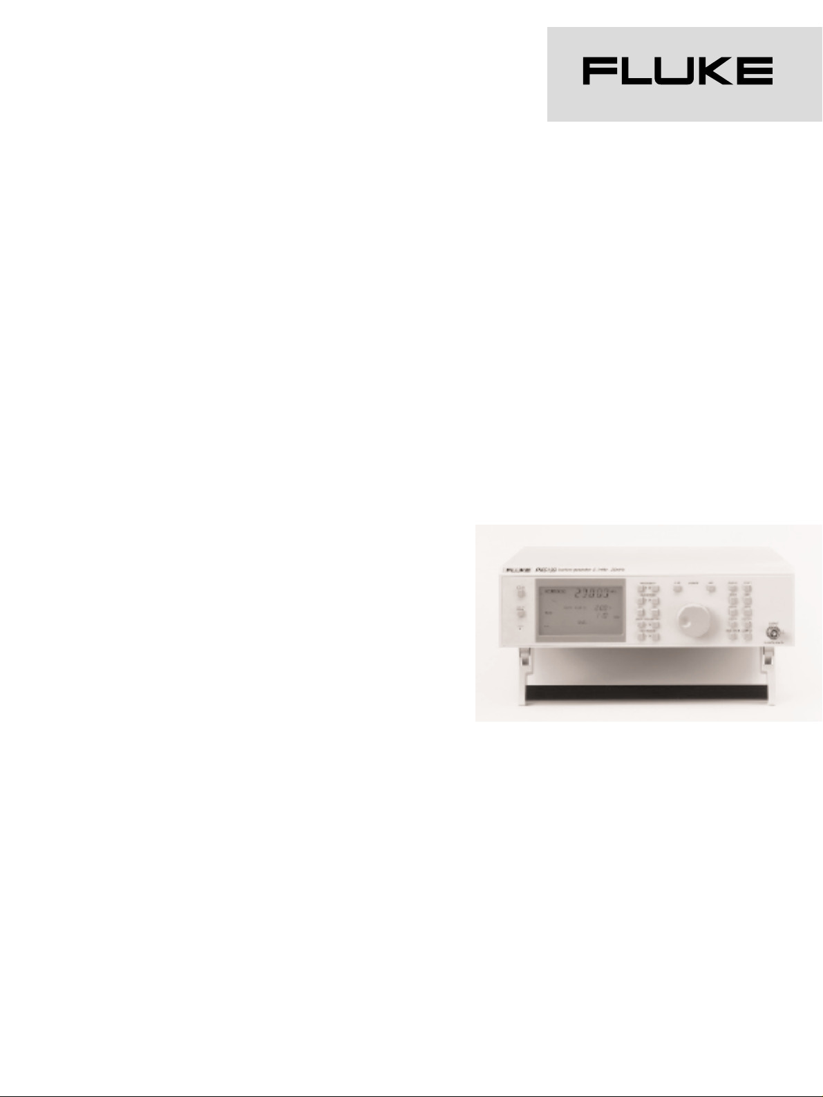
Fluke PM5136, PM5138A, PM5139 Synthesized Function Generators
with arbitrary waveform
Page 2

2
PM 5136
• High performance at a
budget price
• Frequency range from
0.1mHz to 5MHz (20Vpp)
• High accurate signals, low
distortion
• In practice proved
mechanical and electronic
design
• Large backlit display and
easy menu controlled
operation
• Continuously variable
symmetry
• 7 Standard waveforms: sine,
triangle, square, pos/neg
pulse, pos/neg/ sawtooth
• Internal and external
modulation modes: AM, FM,
Lin. Sweep, Log. Sweep and
Burst
• 9 Setting memories
• GPIB/IEEE 488.2 interface
(optional)
PM5138A as PM5136, incl.:
• Output voltage of 40 Vpp for
all waveforms, including
arbitrary
• Frequency from 0.1 mHz to
10 M Hz
• 24 Arbitrary waveformmemories
• Arbitrary functionality
supported via AnyWave™
software package
• AnyWave™ software included
• 9 additional setting memories
to store frequently used
settings
• Arbitrary-waveforms, Gate
and PSK modulation
• Selectable output impedance,
50Ω or 600Ω
• GPIB or RS 232 interface
(optional)
PM5139 as PM5138A, incl:
• Frequency from 0.1 mHz to
20 MHz.
(20Vpp)
• 10 Standard waveforms
including sine and trainle
pulses, haversine
• Programmable modulation
frequencies
• Low output impedance Z
O
.
Wide range of applications
These top-value generators,
built on years of experience,
combine high precision with
easy operation, making it the
ideal choice for a wide range
of applications like automotive,
mechanical, calibration,
telecom, audio, componenttesting, medical, education and
training. Applications that
require higher frequencies are
perfectly suited for the PM5139,
while the PM5138A is
extremely usefull when higher
output voltages are required.
This higher output, 40 Vpp,
available for the complete
bandwidth up to 20 MHz and
also for the 24 arbitrary
waveforms, makes this
instrument ideal for tranducer
simulation up to 14 Vrms for
the automotive industry.
Simple, menu-controlled
operation
To change a setting, all that's
needed is to make a selection
from the 5-line menu and
operate the corresponding
buttons. Specific functions can
be accessed directly via control
buttons which are conveniently
located in a separate field. For
example: store or recall of
instrument-settings. Numeric
values are set precisely by a
large rotary control (which can
be disabled to secure the
setting). At all times, you get a
clear indication of the
instrument setting by the large
backlit LCD display.
Accurate setting of
modulation parameters
Modulation parameters such as
modulation depth, deviation,
number of cycles and start/stop
phase can be set with high
accuracy. The
modulation/trigger source is
programmable with a wide
frequency range of 1 mHz to
100 kHz, and an accuracy of
0.1%. The sweep parameters
f
start,fstop
, time, lin/log and
sweep mode are independently
programmable.
Versatile modulation mode
selection
Modulation modes such as AM,
FM and sweep are selected
from the modulation mode
menu. All waveforms can be
modulated, even the userdefined arbitrary waveforms.
The burst mode can be
triggered via the internal
modulation/trigger source or via
the external modulation input.
Bursts may also be manually
triggered by a front panel key.
The single-shot mode in burst
can be used with all
waveforms, including arbitrary.
Arbitrary waveform function
via GPIB/IEEE-488 / RS232
link
Both the PM 5138A and PM
5139 with GPIB/IEEE-488 or
RS232 installed, provide the
arbitrary waveform capability, a
powerful aid to the generation
of custom test signals.
Application example:
In mechanical vibration
analysis, such as shock testing,
a DSO can capture the output
of an accelerometer and
transfer the vibration waveform
either to a PC for modification
or directly to the PM 5138A or
PM 5139 to reproduce it when
needed, without having to
repeat the actual experiment.
The waveform can then be
sent continuously, as a burst
for a defined number of cycles,
or when triggered by an
external source.
Page 3
3
Model PM 5136 PM 5138A PM 5139
Frequency characteristics
Nominal Range 0.1 mHz – 5 MHz 0.1 mHz - 10 MHz 0.1 mHz – 20 MHz
Operational Range
Sine, pos/neg pulse 5 MHz 10 MHz 20 MHz
Square wave 5 MHz 10 MHz 20 MHz
Triangle 500 kHz 500 kHz 500 kHz
Pos./neg. sawtooth 20 MHz 50 kHz 50 kHz
Sine … , triangle pulse 50 kHz
Haversine 50 kHz
4_ digits, max. 0.1 mHz
Resolution 10 Hz (fC>200kHz)
*3
Setting error ± 2 x 10⁻⁶(± 2 ppm)
(fC≥5MHz) (fC>10MHz)
Residual FM deviation <10ppm, 1ppm typical <10ppm, 1ppm typical
(measuring bandwidth
10Hz-20kHz) <100Hz, 13Hz typical (fC≤5MHz) (fC≤10 MH z )
<100Hz, 13Hz typical <100Hz, 13Hz typical
Phase noise at 1kHz < -80dBc/Hz
distance from carrier
Temperature coëfficient <±0.2ppm / K
Aging <±1ppm / year
Drift <±0.3ppm in 7 hours
Synchronization by an f
REF
=10MHz/N, N=1, 2, 3...10
external reference
Output characteristics
Main Output
Connector BNC socket On front
Impedance 50Ω 50Ω or 600Ω 50Ω or LOW Z
O
Load capability Short circuit proof
Max. external voltage ±15V < 3min 50Ω: ±15V 50Ω: ±15V < 3min
600Ω: ±24V LOW ZO: ±12V < 3min
AC voltage independent of DC setting within: ….
Ranges ± 10V window ± 20V window ± 10V window
I resolution 1 mV 0 - 0.200 Vpp 0 - 0.400 Vpp 0 - 0.200 Vpp
II resolution 10mV 0.20 - 2.00 Vpp 0.40 - 4.00 Vpp 0.20 - 2.00 Vpp
III resolution 100 mV 2.0 - 20.0 Vpp 4.0 - 40.0 Vpp 2.0 - 20.0 Vpp
Accuracy for AC voltages > 10mVpp > 20mVpp > 10mVpp
Basic setting error
*2
±2.0%, 1Hz < fC< 200kHz
Amplitude flatness
*2
fC: 1Hz-200kHz ±0.03dB ±0.03dB ±0.03dB
f
C
: 200kHz -5MHz ±0.07dB ±0.07dB ±0.07dB
fC: 5MHz -10MHz ±0.1dB ±0.1dB
f
C
: 10MHz -20MHz ±0.2dB
DC voltage independent of AC setting within: …
± 10V window ± 20V window ± 10V window
Range (open circuit) ±10V resolution 100mV
Error limits
*2
±2.0% ±50mV ±2.0% ±100mV ±2.0% ±50mV
TTL Output 0/5V, Z0=50Ω BNC on rear panel
Fan-out > 4 TTL inputs
Page 4

4
Model PM 5136 PM 5138A PM 5139
Waveforms
Asymmetrie
fC≤ 20kHz 1% - 99%, resolution 1% sine, square, triangle, pos./neg. pulses
fC: 20kHz - 5MHz 20% - 80%, resolution 1% square, pos./neg. pulses
Sinewave
Frequency range 0.1 mHz – 5 MHz 0.1 mHz - 10 MHz 0.1 mHz - 20 MHz
Output range open circuit 0 – 20 Vpp 0 - 40 Vpp 0 - 20 Vpp
Distortion for output 10-70% of voltage range 25-100% of voltage 10-70% of voltage range
voltages maximum
*2
range maximum
*2
maximum
*2
and frequencies 1Hz - 500kHz 1Hz - 500kHz 1Hz - 500kHz
Total harm.distortion < 0.4%, 0.1% typical < 0.4%, 0.1% typical < 0.4%, 0.1% typical
Harmonics fc:1Hz – 500kHz <-48dBc <-42dBc <-48dBc
Harmonics fc:500kHz-5MHz <-40dBc <-34dBc <-40dBc
Harmonics fc:5MHz–10MHz <-30dBc <-36dBc
Harmonicsfc:10MHz-20MHz <-34dBc
Subharmonics fc < 5MHz <-60dBc <-60dBc <-60dBc
Subharmonics fc > 5MHz <-38dBc <-38dBc
Square, Positive / Negative Pulses
Frequency range 0.1 mHz – 5 MHz 0.1 mHz – 10 MHz 0.1 mHz – 20 MHz
Output range open circuit 0 - 20Vpp 0 - 40Vpp 0 - 20Vpp
Pos/Neg. pulse open circuit 0 – 10 Vpp 0 – 20 Vpp 0 – 10 Vpp
Rise-/Fall time (at 50 % symmetry)
*2
fC: 0.1 mHz - 500 kHz ≤ 30 ns
fC> 500 kHz ≤ 20 ns
Aberration
*2
< 2% (AC > 200 mVpp)
Asymmetry See Waveforms
Triangle
Frequency range 0.1 mHz - 500 kHz
Output range 0 – 20 Vpp 0 – 40 Vpp 0 - 20 Vpp
Linearity error < 0.2% (fC<20 kHz)
Asymmetry See Waveforms
Positive / negative sawtooth
Frequency range 0.1 mHz - 50 kHz
Output range 0 - 10 Vpp 0 - 20 Vpp 0 - 10 Vpp
Linearity error <0.2% (fC< 20kHz)
Sine pulse, triangle pulse, haversine
Frequency range 0.1 mHz - 50 kHz
Output range 0 - 10 Vpp
Arbitrary (Instruments with interface)
Frequency range 0.1 mHz - 20 kHz
Sample frequency max. 20.48 MS/s
Waveform memories 24 (non volatile)
Memory length 1024 (10 bits)
Vertical resolution 1023 (10 bits)
Programmable via interface with a PC or direct with a DSO
Full scale output range 0 - 40Vpp open circuit 0 - 20Vpp open circuit
Page 5

Model PM 5136 PM 5138A PM 5139
Modulation
Modes AM, FM, Burst, Sweep AM, FM, Burst, Sweep, Gate, PSK
AM
Carrier frequency 0.1 mHz - 5 MHz 0.1 mHz - 10 MHz 0.1 mHz - 20 MHz
Carrier waveforms All All incl. arbitrary*1, except PSK
Internal AM
Modulation frequency 1 kHz ± 0.01% 10 Hz – 100 kHz, max. resolution 1 Hz ± 0.1%
Modulation waveform Sine
Modulation Depth 0-100%, resolution 1%
Mod. depth: ≤ 90% <0.5%, <0.15% typical <0.7%,
≤ 90% and fC≤ 15MHz <0.5%, <0.15% typical
External AM
Modulation frequency 0 to 200 kHz
Modulation Depth 0-100%
Mod. depth: ≤ 90% <0.5%, <0.15% typical <0.7%,
≤ 90% and fC ≤ 15MHz <0.5%, <0.15% typical
*
with (.. Ω) output impedance of modulation signal source
FM
Carrier frequency 0.1 mHz - 5 MHz 0.1 mHz - 10 MHz 0.1 mHz - 20 MHz
Carrier waveforms All All incl. arbitrary*1, except PSK
Internal FM
Modulation frequency 1 kHz ± 0.01% 10 Hz – 100 kHz, max. resolution 1 Hz ± 0.1%
Modulation waveform Sine
Deviation 0 – 2 % resolution ± 0.01%
Modulation distortion, <0.4%, typ. 0.12%
THD for 1% deviation
External FM
Modulation frequency 10 Hz to 200 kHz
Deviation 0 – 2 %
Phase Shift Keying (PSK) Carrier phase keying between 0° and 180°, non-coherent
Carrier waveforms Sine, triangle, square
Carrier frequency range Total range
PSK, internal keying freq. 10Hz - 100kHz, 50% duty cycle
PSK, external keying freq. 0 - 200kHz, TTL signal
Burst
Carrier frequency 0.1 mHz - 2 MHz
Carrier waveform All, phase-coherent on/off – switching
On periods per Burst 1 - 2000
Start/Stop - Phase 0° 0°
-180° ...+180°, resolution 1° for sine, triangle and
fC≤ 20kHz
Burst trigger modes
Internal (Manually) Single & Continuous Single & Continuous with
with 1mHz - 100kHz repetition frequency
1kHz ± 0.01% rep. freq
External via Mod. input with 0 - 200kHz repetition frequency
5®6
Page 6

*1
Instruments with GPIB/IEEE 488.2 or RS232 interface
*2
Zo=50Ω, Rl=50Ω, Modulation off
*3
Via GPIB interface
Model PM 5136 PM 5138A PM 5139
Sweep
Carrier waveform All
Sweep functions Single
Continuous
Hold/Release
Reset to start frequency
Sweep characteristics Linear or logarithmic
Up or down
Sweep modes Sweep and flyback
Sweep and hold
Sweep from f
start
to f
stop
and back to f
start
Sweep ranges max. 1mHz - 5MHz 1mHz - 5MHz 1mHz - 10MHz
50kHz - 10MHz 50kHz - 20MHz
Sweep time 10ms - 1000s
Number of frequency steps Sweep time / 1ms
Gate Non-coherent signal keying
Carrier frequencies All
Carrier waveforms All
Gate, internal
Keying frequency 10Hz – 100kHz
Duty cycle 50%
Gate, external
Keying frequency 0 – 200kHz, TTL signal
Interface bus remote control
Isolation in- and outputs galvanically separated with opto-couplers
Control capability all functions and characteristics
GPIB/IEEE-488.2 Address range 0 - 30 and listen only mode
RS232
Baud rate / data ../ 110-19200 / 7 or 8 / 1 / odd, even or no parity
stop bits
Handshake hardware or software (Xon/Xoff)
Miscellaneous
Instrument settings 1 + 9
Rear connectors modulation input / triggering input / reference input / TTL output /
modulation output / penlift output / sweep output / 10 MHz reference output /
interface bus connector *1/ power connector
Dimensions (HxWxD) 105 x 315 x 405 mm
Weight 6.7 kg 6.1 kg 6.7 kg
Operating conditions
Temperature Reference 23°C ± 1°C, Operating + 5 .. +40°C Storage -40 .. +70°C
Safety According to CE regulation 73/23: EN 61010-1, CAT II, Pollution Degree 2
EMC According to CE regulation 89/336:
Emission according to EN 55 011 Group 1 Class B, respectively CISPR 11.
Immunity according to EN 50 082-1, inclusive IEC 801-2, -3, -4.
Power / line frequency 100,120,220,240V / 50 - 60 Hz ± 5%
Power consumption 42W 66W 58W
Page 7

Ordering Information
PM 5136/00n 5 MHz Programmable Function Generator
PM 5136/02n 5 MHz Programmable Function Generator with GPIB/IEEE 488.2 interface
PM 5138A/10n 10 MHz Programmable Function Generator
PM 5138A/12n inclusive GPIB/IEEE-488.2 interface and Arbitrary
PM 5138A/13n inclusive RS232 interface and Arbitrary
PM 5139/00n 20 MHz Programmable Function Generator
PM 5139/02n inclusive GPIB/IEEE-488.2 interface and Arbitrary
PM 5139/03n inclusive RS232 interface and Arbitrary.
Power options
n = 1 Universal European 220 V
n = 3 Standard North American 120V
n = 4 United Kingdom 240 V
n = 5 Switzerland 220 V
n = 8 Australia 240 V
Accessories
PM 9051 BNC to 4 mm banana adapter
PM 9551 50 ohm to 600 ohm Adapter
PM 9581/01 50 ohm feed-through termination 3 W
PM 9585/01 50 ohm feed-through termination 1 W
Y8021 Shielded DEEE-488 Cable, 1m
Y8022 Shielded DEEE-488 Cable, 2m
Y8023 Shielded DEEE-488 Cable, 4m
PM 9564 19 inch Rackmount kit for PM5136/38A/39
Factory Warranty
One year product warranty
Manuals
Operators Manual included with instrument
®
Fluke Corporation
P.O. Box 9090, Everett, WA 98206
Fluke Europe B.V.
P.O. Box 1186,
5602 BD Eindhoven,
The Netherlands
For more information call:
In the U.S.A.: (800) 443-5853
or Fax: (425) 356-5116
In Europe/M-East:
+31 (0)40 2 678 200
or Fax: +31 (0)40 2 678 222
In Canada: (905) 890-7600
or Fax: (905) 890-6866
From other countries:
+1(425) 356-5500
or Fax: +1 (425) 356-5116
Web access: http://www.fluke.com
©Copyright 1999 Fluke Corporation.
All rights reserved. 10175-ENG-02
A0630UEN A
7
 Loading...