

Fluke OF-500-10, OF-500-02, OF-500-03, OF-500-13, OF-500-15 Technical Reference Handbook
...Page 1

OF-500 OptiFiber®
Certifying OTDR
Technical Reference Handbook
September 2002, Rev. 4 6/06
© 2002-2006 Fluke Corporation. All rights reserved.
All product names are trademarks of their respective companies.
Page 2

LIMITED WARRANTY AND LIMITATION OF LIABILITY
Each Fluke Networks product is warranted to be free from defects in material and workmanship under normal use and service. The warranty
period for the mainframe is one year and begins on the date of purchase. Parts, accessories, product repairs and services are warranted for
90 days, unless otherwise stated. Ni-Cad, Ni-MH and Li-Ion batteries, cables or other peripherals are all considered parts or accessories. The
warranty extends only to the original buyer or end user customer of a Fluke Networks authorized reseller, and does not apply to any product which, in Fluke Networks’ opinion, has been misused, abused, altered, neglected, contaminated, or damaged by accident or abnormal
conditions of operation or handling. Fluke Networks warrants that software will operate substantially in accordance with its functional
specifications for 90 days and that it has been properly recorded on non-defective media. Fluke Networks does not warrant that software
will be error free or operate without interruption.
Fluke Networks authorized resellers shall extend this warranty on new and unused products to end-user customers only but have no authority to extend a greater or different warranty on behalf of Fluke Networks. Warranty support is available only if product is purchased
through a Fluke Networks authorized sales outlet or Buyer has paid the applicable international price. Fluke Networks reserves the right to
invoice Buyer for importation costs of repair/replacement parts when product purchased in one country is submitted for repair in another
country.
Fluke Networks' warranty obligation is limited, at Fluke Networks' option, to refund of the purchase price, free of charge repair, or replacement of a defective product which is returned to a Fluke Networks authorized service center within the warranty period.
To obtain warranty service, contact your nearest Fluke Networks authorized service center to obtain return authorization information, then
send the product to that service center, with a description of the difficulty, postage and insurance prepaid (FOB Destination). Fluke Networks assumes no risk for damage in transit. Following warranty repair, the product will be returned to Buyer, transportation prepaid (FOB
Destination). If Fluke Networks determines that failure was caused by neglect, misuse, contamination, alteration, accident or abnormal
condition of operation or handling, or normal wear and tear of mechanical components, Fluke Networks will provide an estimate of repair
costs and obtain authorization before commencing the work. Following repair, the product will be returned to the Buyer transportation
prepaid and the Buyer will be billed for the repair and return transportation charges (FOB Shipping Point).
THIS WARRANTY IS BUYER'S SOLE AND EXCLUSIVE REMEDY AND IS IN LIEU OF ALL OTHER WARRANTIES, EXPRESS OR IMPLIED, INCLUDING
BUT NOT LIMITED TO ANY IMPLIED WARRANTY OF MERCHANTABILITY OR FITNESS FOR A PARTICULAR PURPOSE. FLUKE NETWORKS SHALL
NOT BE LIABLE FOR ANY SPECIAL, INDIRECT, INCIDENTAL OR CONSEQUENTIAL DAMAGES OR LOSSES, INCLUDING LOSS OF DATA, ARISING
FROM ANY CAUSE OR THEORY.
Since some countries or states do not allow limitation of the term of an implied warranty, or exclusion or limitation of incidental or consequential damages, the limitations and exclusions of this warranty may not apply to every buyer. If any provision of this Warranty is held
invalid or unenforceable by a court or other decision-maker of competent jurisdiction, such holding will not affect the validity or enforceability of any other provision.
4/04
Fluke Networks
PO Box 777
Everett, WA 98206-0777
USA
Page 3

Table of Contents
Chapter Title Page
1 Getting Acquainted ...................................................................................................... 1-1
Overview of Features.................................................................................................... 1-1
Registration................................................................................................................... 1-2
Contacting Fluke Networks .......................................................................................... 1-3
Unpacking ..................................................................................................................... 1-3
Model OF-500-01...................................................................................................... 1-3
Model OF-500-02...................................................................................................... 1-4
Model OF-500-03...................................................................................................... 1-4
Model OF-500-10...................................................................................................... 1-5
Model OF-500-13...................................................................................................... 1-5
Model OF-500-15...................................................................................................... 1-6
Model OF-500-35...................................................................................................... 1-6
Model OF-500-45...................................................................................................... 1-7
Powering the Tester...................................................................................................... 1-8
Charging the Battery ............................................................................................... 1-8
i
Page 4

OF-500 OptiFiber
Technical Reference Handbook
2 Getting Started Testing Fiber...................................................................................... 2-1
Checking the Battery Status.................................................................................... 1-8
Changing the Language............................................................................................... 1-10
Removing and Installing the Module.......................................................................... 1-10
Verifying Operation ..................................................................................................... 1-10
Basic Features ............................................................................................................... 1-12
Front Panel Features................................................................................................ 1-12
Side and Top Panel Features ................................................................................... 1-14
The HOME Screen .................................................................................................... 1-16
Using the Setup Menus ........................................................................................... 1-18
Checking the Software and Hardware Versions .................................................... 1-20
Using the Online Help ............................................................................................. 1-20
Overview of Memory Features................................................................................ 1-21
Using the Memory Card...................................................................................... 1-21
Using the Internal Memory ................................................................................ 1-22
Using an External Keyboard.................................................................................... 1-22
Setting User Preferences .............................................................................................. 1-24
Changing the Date, Time, and Numeric Formats................................................... 1-24
Changing the Length Units..................................................................................... 1-24
Enabling or Disabling the Save Warning................................................................ 1-24
Adjusting the Display Brightness ............................................................................ 1-24
Using the Power Down Timer ................................................................................. 1-25
Enabling or Disabling the Beeper........................................................................... 1-25
Changing the Logo on the HOME Screen .............................................................. 1-26
Enabling Software Options.......................................................................................... 1-27
About LinkWare and LinkWare Stats Software.......................................................... 1-27
Safety Information ....................................................................................................... 2-1
ii
Page 5

Contents
Cleaning and Inspecting Fiber Connectors and Adapters........................................... 2-4
Testing Your Reference Test Cords and Launch Fiber................................................. 2-5
General Test Settings.................................................................................................... 2-6
Selecting a Test Mode.............................................................................................. 2-6
Selecting a Fiber Type.............................................................................................. 2-6
Viewing Fiber Properties ......................................................................................... 2-7
Selecting a Test Limit ............................................................................................... 2-7
Viewing Test Limits .................................................................................................. 2-8
If the Test Limit or Fiber Type is Not Valid with the Test....................................... 2-8
Entering Job Settings............................................................................................... 2-8
Changing the Index of Refraction........................................................................... 2-10
Tutorial: Preparing to Save Tests.................................................................................. 2-11
Step 1: Creating a List of Sequential Fiber IDs........................................................ 2-11
Step 2: Setting Up a Job Folder ............................................................................... 2-12
Step 3: Entering the Operator Name ...................................................................... 2-12
Step 4: Identifying the Cabling Ends....................................................................... 2-12
Step 5: Setting the Save Warning............................................................................ 2-12
Tutorial: Running an OTDR Test................................................................................... 2-14
Required Equipment................................................................................................ 2-14
Step 1: Selecting Auto OTDR Mode ........................................................................ 2-15
Step 2: Selecting a Fiber Type and Test Limit ......................................................... 2-15
Step 3: Selecting a Wavelength............................................................................... 2-15
Step 4: Testing in the First Direction....................................................................... 2-15
Step 5: Viewing the Results ..................................................................................... 2-17
Step 5: Viewing the Results ..................................................................................... 2-17
Step 6: Saving Results from the First Direction....................................................... 2-17
Step 7: Testing in the Second Direction.................................................................. 2-17
Step 8: Saving Results from the Second Direction.................................................. 2-17
(continued)
iii
Page 6

OF-500 OptiFiber
Technical Reference Handbook
3 Using the OTDR ............................................................................................................ 3-1
Tutorial: Running a Loss/Length Test .......................................................................... 2-18
Required Equipment................................................................................................ 2-18
Step 1: Selecting Loss/Length Test Mode................................................................ 2-18
Step 2: Selecting a Fiber Type ................................................................................. 2-18
Step 3: Configuring the Loss/Length Test............................................................... 2-19
Step 4: Setting the Reference ................................................................................. 2-19
Step 5: Running the Test ......................................................................................... 2-21
Step 6: Viewing the Results..................................................................................... 2-21
Step 7: Saving the Results........................................................................................ 2-21
Fiber ID Options............................................................................................................ 2-23
Using the Auto Increment Feature ......................................................................... 2-23
Creating a List of Sequential IDs............................................................................. 2-24
About ANSI/TIA/EIA-606-A Fiber IDs ....................................................................... 2-25
Horizontal Link Identifier................................................................................... 2-25
Backbone Cable Identifier .................................................................................. 2-25
Campus Cable Identifier ..................................................................................... 2-26
Using Downloaded Fiber IDs................................................................................... 2-26
Solving Problems with Fiber ID Lists ....................................................................... 2-26
Adding Comments to Test Results............................................................................... 2-28
Setting Up for OTDR Testing ....................................................................................... 3-1
Cleaning the OTDR Connector................................................................................ 3-2
Selecting Auto or Manual OTDR Mode.................................................................. 3-3
About Launch and Receive Fibers........................................................................... 3-3
Compensating for Launch and Receive Fibers................................................... 3-4
Types of Compensation ...................................................................................... 3-4
Setting the Launch Fiber Compensation ........................................................... 3-5
iv
Page 7

Contents
Settings for OTDR Tests ........................................................................................... 3-10
OTDR Connection Quality ............................................................................................ 3-14
Progress Screen for Extended Test Times (OFTM-573x Modules)............................... 3-16
Running the OTDR Test ................................................................................................ 3-17
Looking at OTDR Test Results....................................................................................... 3-22
Reading the SUMMARY Screen............................................................................... 3-22
Reading the OTDR Trace.......................................................................................... 3-24
Using the Measurement Cursor............................................................................... 3-28
Zooming the Trace................................................................................................... 3-29
Reading the Event Table.......................................................................................... 3-30
Event Types.......................................................................................................... 3-32
Sorting Events...................................................................................................... 3-37
OTDR DETAILS Screens............................................................................................. 3-38
Warning Messages .............................................................................................. 3-38
Attenuation Coefficient...................................................................................... 3-38
ORL (Optical Return Loss).................................................................................... 3-38
Segment Attenuation Coefficient ...................................................................... 3-38
Reflectance .......................................................................................................... 3-38
Bi-Directional Testing ................................................................................................... 3-39
Comparing OTDR Traces............................................................................................... 3-39
Using the Real Time Trace ............................................................................................ 3-44
Using Manual OTDR Mode........................................................................................... 3-46
Diagnosing OTDR Test Failures .................................................................................... 3-51
4 Using the ChannelMap Function ................................................................................. 4-1
Running the Test........................................................................................................... 4-1
ChannelMap Diagram Features.................................................................................... 4-4
(continued)
v
Page 8

OF-500 OptiFiber
Technical Reference Handbook
5 Using the FiberInspector Option................................................................................. 5-1
6 Using the Loss/Length Option..................................................................................... 6-1
Using the Probe............................................................................................................ 5-2
FiberInspector Image Examples ................................................................................... 5-6
Getting a Good Image.................................................................................................. 5-7
Using the Core Scale..................................................................................................... 5-8
Overview of Features ................................................................................................... 6-1
About Smart Remotes .................................................................................................. 6-2
Changing the Connector Adapter ............................................................................... 6-2
Cleaning the Loss/Length Connectors ......................................................................... 6-5
Cleaning the OUTPUT Connector............................................................................ 6-5
Cleaning the INPUT Connector ............................................................................... 6-5
Verifying Operation ..................................................................................................... 6-6
Loss/Length Test Settings ............................................................................................. 6-6
About Method B Connections ..................................................................................... 6-13
About Setting the Reference....................................................................................... 6-13
Using Mandrels for Testing Multimode Fiber............................................................. 6-15
Testing in Smart Remote Mode................................................................................... 6-17
Testing in Smart Remote Mode................................................................................... 6-17
Setting the Reference in Smart Remote Mode ...................................................... 6-18
Running the Test in Smart Remote Mode.............................................................. 6-20
Smart Remote Mode Test Results ........................................................................... 6-22
Testing in Loopback Mode........................................................................................... 6-24
Setting the Reference in Loopback Mode.............................................................. 6-26
Running the Test in Loopback Mode...................................................................... 6-28
Loopback Mode Test Results................................................................................... 6-28
vi
Page 9

Contents
Testing in Far End Source Mode................................................................................... 6-32
Required Equipment................................................................................................ 6-32
Setting the Reference in Far End Source Mode...................................................... 6-34
Running the Test in Far End Source Mode ............................................................. 6-36
Using Auto Wavelength Detection with SimpliFiber Sources
(OFTM-5731 and OFTM-5732 Modules) .................................................................. 6-36
Far End Source Mode Test Results........................................................................... 6-38
Bi-Directional Testing ................................................................................................... 6-40
Bi-Directional Testing in Smart Remote or Loopback Mode.................................. 6-40
Bi-Directional Testing in Far End Source Mode...................................................... 6-40
Diagnosing Loss/Length Test Failures .......................................................................... 6-40
Finding Connections with FindFiber ............................................................................ 6-43
Using FindFiber in Smart Remote Mode................................................................. 6-43
Using FindFiber in Loopback Mode......................................................................... 6-46
7 Using the Visual Fault Locator ..................................................................................... 7-1
Visual Fault Locator Applications................................................................................. 7-1
Using the VFL ................................................................................................................ 7-2
8 Using the Power Meter Option.................................................................................... 8-1
Running the Test........................................................................................................... 8-2
Using Auto Wavelength Detection with SimpliFiber Sources
(OFTM-5731 and OFTM-5732 Modules) .................................................................. 8-2
Power Meter Results ................................................................................................ 8-5
If the Power Reading is Low......................................................................................... 8-6
9 Memory Functions........................................................................................................ 9-1
About Saving Tests........................................................................................................ 9-1
(continued)
vii
Page 10

OF-500 OptiFiber
Technical Reference Handbook
10 Creating Custom Fiber Types and Test Limits ............................................................ 10-1
11 Maintenance and Specifications ................................................................................. 11-1
Memory Capacity and Card Sizes Supported .............................................................. 9-2
Formatting a Memory Card ......................................................................................... 9-2
Memory Card Care ....................................................................................................... 9-4
Reviewing and Managing Saved Records ................................................................... 9-4
About Memory Card Folders........................................................................................ 9-7
Changing or Creating Folders ................................................................................. 9-7
Deleting Folders....................................................................................................... 9-7
Viewing Folders on a PC.......................................................................................... 9-8
Creating Custom Fiber Types ....................................................................................... 10-1
Creating Custom Test Limits ........................................................................................ 10-4
Selecting a Custom Limit.............................................................................................. 10-8
If the Limit or Fiber Type is Not Valid.......................................................................... 10-8
Maintenance................................................................................................................. 11-1
Updating the Tester’s Software .............................................................................. 11-2
Updating via the USB or Serial Port................................................................... 11-3
Updating via a Memory Card Created with LinkWare...................................... 11-3
Optical Connector Care ........................................................................................... 11-5
Replacing Reference Test Cords and Launch Fibers............................................... 11-5
Replacing the Battery.............................................................................................. 11-5
Cleaning ................................................................................................................... 11-6
Storage.......................................................................................................................... 11-6
Calibration .................................................................................................................... 11-6
If Something Seems Wrong ......................................................................................... 11-7
Getting Help ............................................................................................................ 11-7
viii
Page 11

Contents
Options and Accessories ............................................................................................... 11-10
Specifications................................................................................................................. 11-17
Environmental and Regulatory Specifications........................................................ 11-17
OTDR Specifications for OFTM-561xB Multimode Modules................................... 11-18
OTDR Specifications for OFTM-573x Singlemode Modules.................................... 11-21
Power Meter Specifications ..................................................................................... 11-25
Loss/Length Specifications ....................................................................................... 11-27
Power........................................................................................................................ 11-32
Traceable Calibration Period ................................................................................... 11-32
Certifications and Compliance................................................................................. 11-32
Memory for Test Results .......................................................................................... 11-32
Serial Interfaces........................................................................................................ 11-33
Keyboard Port .......................................................................................................... 11-34
Video Port for FiberInspector Probe ....................................................................... 11-34
Dimensions (with module and battery installed) ................................................... 11-34
Weight (with module and battery installed).......................................................... 11-34
Display ...................................................................................................................... 11-34
Fan ............................................................................................................................ 11-34
FiberInspector Probe Specifications ........................................................................ 11-35
Appendices
A Test Method Reference Tables.............................................................................. A-1
B Loss Test Methods.................................................................................................. B-1
C Common Causes of Fiber Link Failures ................................................................. C-1
Index
(continued)
ix
Page 12

OF-500 OptiFiber
Technical Reference Handbook
x
Page 13

List of Tables
Table Title Page
2-1. International Electrical Symbols .......................................................................................... 2-1
2-2. Job Settings .......................................................................................................................... 2-9
2-3. Solving Problems with Fiber ID Lists.................................................................................... 2-27
3-1. Settings for OTDR Tests ....................................................................................................... 3-10
3-2. OTDR SUMMARY Screen Features....................................................................................... 3-22
3-3. Event Table Features............................................................................................................ 3-30
3-4. Event Types........................................................................................................................... 3-32
3-5. Manual OTDR Settings......................................................................................................... 3-46
3-6. Diagnosing OTDR Test Failures ........................................................................................... 3-51
5-1. Getting a Good FiberInspector Image................................................................................. 5-8
6-1. Loss/Length Test Settings..................................................................................................... 6-6
6-2. Typical Reference Values ..................................................................................................... 6-14
6-3. TIA/EIA-568-B.1 and ISO/IEC TR 14763-3 Mandrel Requirements ...................................... 6-15
6-4. Smart Remote Mode SUMMARY Screen Features.............................................................. 6-22
6-5. Smart Remote Mode RESULTS Screen Features.................................................................. 6-23
xi
Page 14

OF-500 OptiFiber
Technical Reference Handbook
6-6. Loopback Mode SUMMARY Screen Features..................................................................... 6-30
6-7. Loopback Mode RESULTS Screen Features......................................................................... 6-31
6-8. Far End Source Mode SUMMARY Screen Features ............................................................ 6-38
6-9. Far End Source Mode RESULTS Screen Features ................................................................ 6-39
6-10. Diagnosing Loss/Length Test Failures................................................................................. 6-41
6-11. Main Tester Results for FindFiber Test (Smart Remote Mode).......................................... 6-44
9-1. Memory Status Screen Features.......................................................................................... 9-3
9-2. Record Viewing and Management Functions.................................................................... 9-5
10-1. Fiber Property Settings........................................................................................................ 10-3
10-2. Custom Limit Settings for OTDR Tests ................................................................................ 10-6
10-3. Custom Limit Settings for Loss/Length Tests...................................................................... 10-7
11-1. Troubleshooting the Tester................................................................................................. 11-8
11-2. Options................................................................................................................................. 11-10
11-3. Accessories ........................................................................................................................... 11-11
11-4. RS-232 Interface Cable Connections ................................................................................... 11-33
11-5. 9-to-25-Pin Adapter............................................................................................................. 11-34
A-1. Test Method Names............................................................................................................. A-1
A-2. Test Methods Required by Standards................................................................................. A-2
C-1. Fiber Failure Survey Results................................................................................................. C-1
xii
Page 15

List of Figures
Figure Title Page
1-1. Battery Pack Features........................................................................................................... 1-9
1-2. Removing the Module ......................................................................................................... 1-11
1-3. Front Panel Features ............................................................................................................ 1-12
1-4. Side and Top Panel Features ............................................................................................... 1-14
1-5. Home Screen for OTDR with Loss/Length Option .............................................................. 1-16
1-6. The SETUP Screen ................................................................................................................. 1-18
1-7. The Setup Menus ................................................................................................................. 1-19
1-8. Inserting and Removing the Memory Card ........................................................................ 1-22
1-9. Using an External Keyboard................................................................................................ 1-23
2-1. Using the Text Editing Screen ............................................................................................. 2-13
2-2. Typical OTDR Connections and Trace Features .................................................................. 2-16
2-3. Smart Remote Mode Reference Connections..................................................................... 2-20
2-4. Smart Remote Mode Test Connections............................................................................... 2-22
3-1. Cleaning the OTDR Connector ............................................................................................ 3-2
3-2. Launch Only Compensation Connections ........................................................................... 3-7
xiii
Page 16

OF-500 OptiFiber
Technical Reference Handbook
3-3. Launch + Receive Compensation Connections................................................................... 3-7
3-4. Launch + Fiber + Receive Compensation Connections ...................................................... 3-8
3-5. OTDR Trace with Launch Compensation Enabled ............................................................. 3-9
3-7. Traces Showing Good and Bad OTDR Connections ........................................................... 3-15
3-8. OFTM-573x Progress Screen for Extended Test Times ....................................................... 3-16
3-9. Equipment for OTDR Tests .................................................................................................. 3-17
3-10. Connecting the OTDR to Installed Fiber (no receive fiber) ............................................... 3-19
3-11. Connecting the OTDR to Installed Fiber (with receive fiber) ............................................ 3-20
3-12. Connecting the OTDR to Spooled Cable ............................................................................ 3-21
3-13. OTDR Trace Screen (launch compensation disabled)......................................................... 3-24
3-14. Typical OTDR Trace Features............................................................................................... 3-26
3-15. OTDR Functions Menu......................................................................................................... 3-41
3-16. Comparing OTDR Traces...................................................................................................... 3-42
4-1. Equipment for ChannelMap Tests ...................................................................................... 4-2
4-2. ChannelMap Test Connections ........................................................................................... 4-3
4-3. ChannelMap Diagram Features .......................................................................................... 4-4
5-1. Equipment for FiberInspector Tests.................................................................................... 5-3
5-2. Using the FiberInspector Probe........................................................................................... 5-4
5-3. FiberInspector Screen .......................................................................................................... 5-5
5-4. FiberInspector Image Examples .......................................................................................... 5-7
5-5. FiberInspector Core Scale (all rings shown)........................................................................ 5-8
6-1. SC, ST, LC, and FC Connector Adapters .............................................................................. 6-3
6-2. Changing the Connector Adapter ...................................................................................... 6-4
6-3. Example of How to Determine the NUMBER OF ADAPTERS Setting................................ 6-11
6-4. Wrapping a Reference Test Cord Around a Mandrel........................................................ 6-16
6-5. Equipment for Testing in Smart Remote Mode................................................................. 6-17
6-6. Smart Remote Mode Reference Connections (Method B)................................................. 6-19
6-7. Smart Remote Mode Test Connections (Method B) .......................................................... 6-21
xiv
Page 17

Contents
6-8. Equipment for Testing in Loopback Mode......................................................................... 6-25
6-9. Loopback Mode Reference Connections (Method B)......................................................... 6-27
6-10. Loopback Mode Test Connections (Method B) .................................................................. 6-29
6-11. Equipment for Testing in Far End Source Mode ................................................................ 6-33
6-12. Far End Source Mode Reference Connections (Method B)................................................ 6-35
6-13. Far End Source Mode Test Connections (Method B).......................................................... 6-37
6-14. Equipment for Using FindFiber in Smart Remote Mode.................................................... 6-43
6-15. Using FindFiber in Smart Remote Mode ............................................................................. 6-45
6-16. Equipment for Using FindFiber in Loopback Mode ........................................................... 6-46
6-17. Using FindFiber in Loopback Mode..................................................................................... 6-47
7-1. Equipment for Using the Visual Fault Locator ................................................................... 7-2
7-2. Using the Visual Fault Locator............................................................................................. 7-4
8-1. Equipment for Power Meter Tests ...................................................................................... 8-3
8-2. Connections for Monitoring Optical Power ....................................................................... 8-4
8-3. The Power Meter Screen...................................................................................................... 8-5
10-1. LIMIT TABLE EDITOR Screen ................................................................................................ 10-5
11-1. Event and Attenuation Deadzone Measurement Methods............................................... 11-22
B-1. Method A/A.2 Reference and Test Connections (singlemode shown).............................. B-3
B-2. Method B/A.1 Reference and Test Connections (singlemode shown)............................... B-5
B-3. Method C/A.3 Reference and Test Connections (singlemode shown)............................... B-7
B-4. Modified Method B: Smart Remote Mode Reference Connections.................................. B-9
B-5. Modified Method B: Smart Remote Mode Test Connections............................................ B-10
B-6. Alternate Method Reference and Test Connections for a Hybrid Link
(singlemode shown)............................................................................................................. B-12
B-7. Alternate Method Test Connections for a Link with MT-RJ Connectors
(singlemode shown)............................................................................................................. B-13
(continued)
xv
Page 18

OF-500 OptiFiber
Technical Reference Handbook
xvi
Page 19

Chapter 1
Getting Acquainted
Note
While this manual describes specific operating
procedures for the OptiFiber tester, the fiber
test methods described are provided only as
guidelines. Your test methods may vary.
Overview of Features
The OF-500 OptiFiber® Certifying OTDR (hereafter
referred to as the tester) is a hand-held Optical Time
Domain Reflectometer (OTDR) that locates and
characterizes reflective and loss events in multimode and
singlemode fibers. The tester is optimized for use on the
shorter fiber runs typically installed in premises (building
and campus) networks. Typical test ranges are up to
7 km at 1300 nm for multimode fiber and up to 60 km
for singlemode fiber.
The tester offers the following features:
• Automated OTDR trace and event analysis help you
identify and locate faults on multimode (850 nm and
1300 nm; 50 μm and 62.5 μm) and singlemode
(1310 nm and 1550 nm; 9 μm) fiber.
• Displays OTDR results in summary format, as a table
of events, or as an interpretive OTDR trace.
PASS/FAIL results are based on factory-installed limits
or limits you specify.
™
• ChannelMap
of the connectors and segment lengths in a channel.
• Optional FiberInspector
inspect fiber endfaces and save the images.
function provides an intuitive diagram
™
Video Probe lets you
1-1
Page 20

OF-500 OptiFiber Certifying OTDR
Technical Reference Handbook
• Optional modules add visual fault locator
(OFTM-57xx only), power meter, and loss/length test
set functions to the standard OTDR.
• Interchangeable connector adapters on the input
ports of the loss/length modules allow ISO-compliant
reference and test connections with a variety of
connector types.
• Saves hundreds of test results on a removable
memory card or in internal memory.
• Context-sensitive online help gives you quick access
to operating instructions and fiber troubleshooting
information.
• LinkWare
PC and create professional-quality test reports. The
LinkWare Stats option generates browsable,
graphical reports of cable test statistics.
software lets you upload test results to a
Registration
Registering your product with Fluke Networks gives you
access to valuable information on product updates,
troubleshooting tips, and other support services.
To register, fill out the online registration form on the
Fluke Networks website at
www.flukenetworks.com/registration.
1-2
Page 21

Getting Acquainted
Contacting Fluke Networks 1
Contacting Fluke Networks
Note
If you contact Fluke Networks about your tester,
have the tester's software and hardware version
numbers available if possible.
www.flukenetworks.com
support@flukenetworks.com
+1-425-446-4519
• Australia: 61 (2) 8850-3333 or 61 (3) 9329 0244
• Beijing: 86 (10) 6512-3435
• Brazil: 11 3044 1277
• Canada: 1-800-363-5853
• Europe: +44-(0)1923-281-300
• Hong Kong: 852 2721-3228
• Japan: 03-3434-0510
• Korea: 82 2 539-6311
• Singapore: 65-6799-5566
• Taiwan: (886) 2-227-83199
• USA: 1-800-283-5853
Visit our website for a complete list of phone numbers.
Unpacking
The OF-500 OptiFiber packages come with the accessories
listed below. If something is damaged or missing, contact
the place of purchase immediately.
Model numbers followed by a "/50M" include
50/125 µm accessories instead of 62.5/125 µm accessories
Model OF-500-01
• OF-500 OptiFiber tester with battery pack
• OFTM-5610B multimode OTDR module
• 62.5/125 µm multimode launch fiber (gray zipper),
100 m, SC/SC
• Protective carrying case for tester
• Carrying strap
• Memory card
• USB cable for PC communications
• AC adapter
• Users Manual
• Product Manuals CD
• LinkWare Software CD
1-3
Page 22

OF-500 OptiFiber Certifying OTDR
Technical Reference Handbook
Model OF-500-02
• OF-500 OptiFiber tester with battery pack
• OFTM-5611B multimode OTDR module with power
meter option
• 62.5/125 µm multimode launch fiber (gray zipper),
100 m, SC/SC
• Two 62.5/125 µm multimode duplex reference test
cords, 2 m, SC/SC
• Two gray mandrels for 62.5/125 µm fiber with 3 mm
jackets
• Protective carrying case for tester
• Carrying strap
• Memory card
• USB cable for PC communications
• AC adapter
• Users Manual
• Product Manuals CD
• LinkWare Software CD
Model OF-500-03
• OF-500 OptiFiber tester with battery pack
• OFTM-5730 singlemode OTDR module
• 9/125 µm singlemode launch fiber (yellow zipper),
130 m, SC/SC
• Protective carrying case for tester
• Carrying strap
• Memory card
• USB cable for PC communications
• AC adapter
• Users Manual
• Product Manuals CD
• LinkWare Software CD
1-4
Page 23

Getting Acquainted
Unpacking 1
Model OF-500-10
• OF-500 OptiFiber tester with battery pack
• OFTM-5612B multimode OTDR module with power
meter and loss/length options
• OFTM-5352 FiberInspector Video Probe (250X/400X)
with adapter tip kit
• 62.5/125 µm multimode launch fiber (gray zipper),
100 m , SC/SC
• Two 62.5/125 µm multimode duplex reference test
cords, 2 m, SC/SC
• Two gray mandrels for 62.5/125 µm fiber with 3 mm
jackets
• Protective carrying case for tester
• Carrying strap
• Soft carrying case for accessories
• Memory card
• USB memory card reader
• USB cable for PC communications
• AC adapter
• Users Manual
• Product Manuals CD
• LinkWare Software CD
Model OF-500-13
• OF-500 OptiFiber tester with battery pack
• OFTM-5732 singlemode OTDR module with power
meter and loss/length options
• DTX Smart Remote with DTX-SFM2 singlemode fiber
module and interchangeable SC adapter
• OFTM-5352 FiberInspector Video Probe (250X/400X)
with adapter tip kit
• 9/125 µm singlemode launch fiber (yellow zipper),
130 m , SC/SC
• Two 9/125 µm singlemode duplex reference test
cords, 2 m, SC/SC
• Carrying strap
• Hard carrying case for tester
• Soft carrying case for accessories
• Memory card
• USB memory card reader
• USB cable for PC communications
• AC adapter
• Users Manual
• Product Manuals CD
• LinkWare Software CD
1-5
Page 24

OF-500 OptiFiber Certifying OTDR
Technical Reference Handbook
Model OF-500-15
• OF-500 OptiFiber tester with battery pack
• OFTM-5612B multimode OTDR module with power
meter and loss/length options
• DTX Smart Remote with DTX-MFM2 multimode fiber
module and interchangeable SC adapter
• OFTM-5352 FiberInspector Video Probe (250X/400X)
with adapter tip kit
• 62.5/125 µm multimode launch fiber (gray zipper),
100 m , SC/SC
• Two 62.5/125 µm multimode duplex reference test
cords, 2 m, SC/SC
• Two gray mandrels for 62.5/125 µm fiber with 3 mm
jackets
• OptiFiber carrying strap
• Smart Remote carrying strap
• Soft carrying case for accessories
• Hard carrying case for tester
• Memory card
• USB memory card reader
• USB cable for PC communications
• Mini-B USB cable for OptiFiber Smart Remote
• Two AC adapters
• OptiFiber Users Manual
• OptiFiber Product Manuals CD
• Smart Remote Users Manual
• Smart Remote Product CD
• LinkWare Software CD
Model OF-500-35
• OF-500 OptiFiber tester with battery pack
• OFTM-5612B multimode OTDR module with power
meter and loss/length options
• OFTM-5732 singlemode OTDR module with power
meter and loss/length options
• OFTM-5352 FiberInspector Video Probe (250X/400X)
with adapter tip kit
• 62.5/125 µm multimode launch fiber (gray zipper),
100 m , SC/SC
• 9/125 µm singlemode launch fiber (yellow zipper),
130 m , SC/SC
• Two 62.5/125 µm multimode duplex reference test
cords, 2 m, SC/SC
• Two gray mandrels for 62.5/125 µm fiber with 3 mm
jackets
• Two 9/125 µm singlemode duplex reference test
cords, 2 m, SC/SC
• Carrying strap
• Soft carrying case for accessories
1-6
Page 25

Getting Acquainted
Unpacking 1
• Hard carrying case for tester
• Memory card
• USB memory card reader
• USB cable for PC communications
• AC adapter
• Users Manual
• Product Manuals CD
• LinkWare Software CD
Model OF-500-45
• OF-500 OptiFiber tester with battery pack
• OFTM-5612B multimode OTDR module with power
meter and loss/length options
• OFTM-5732 singlemode OTDR module with power
meter and loss/length options
• DTX Smart Remote with DTX-MFM2 multimode fiber
module and interchangeable SC adapter
• DTX-SFM2 singlemode fiber module and
interchangeable SC adapter
• OFTM-5352 FiberInspector Video Probe (250X/400X)
with adapter tip kit
• 62.5/125 µm multimode launch fiber (gray zipper),
100 m , SC/SC
• 50/125 µm multimode launch fiber (aqua zipper),
100 m , SC/SC
• 9/125 µm singlemode launch fiber (yellow zipper),
130 m , SC/SC
• Two 62.5/125 µm multimode duplex reference test
cords, 2 m, SC/SC
• Two 50/125 µm multimode duplex reference test
cords, 2 m, SC/SC
• Two red mandrels for 62.5/125 µm fiber with 3 mm
jackets
• Two gray mandrels for 62.5/125 µm fiber with 3 mm
jackets
• Two 9/125 µm singlemode duplex reference test
cords, 2 m, SC/SC
• Carrying strap
• Protective carrying case for accessories
• Hard carrying case for tester
• Protective carrying case for tester
• Memory card reader
• Memory card
• USB cable for PC communications
• Two AC adapters
• Users Manual
• Product Manuals CD
• LinkWare Software CD
1-7
Page 26

OF-500 OptiFiber Certifying OTDR
Technical Reference Handbook
Powering the Tester
*
W
Warning
Read the safety information at the beginning of
Chapter 2 before using the tester.
You can power the tester with the ac adapter included or
with the removable lithium ion battery pack.
Press I to turn the tester on.
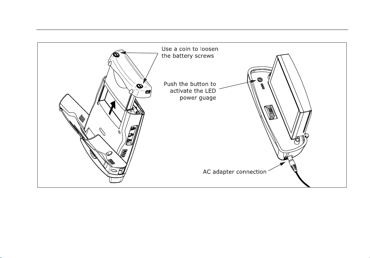
Charging the Battery
Before you rely on battery power for the first time, charge
the battery for about 2 hours with the tester turned off.
You can also charge the battery when it is detached from
the tester, as shown in Figure 1-1.
A fully-charged battery lasts about 8 hours during typical
use. The battery typically takes about 4 hours to fully
charge when the tester is turned off.
Notes
You do not need to fully discharge the battery
before recharging it.
The battery will not charge if its temperature is
outside the range of 32 °F to 113 °F (0 °C to
45 °C).
Checking the Battery Status
Many of the tester’s screens show a battery status icon
( ) near the lower-right corner.
To see more information about the battery status press
F; then select Battery Status. Press H for detailed
information about the battery status screen.
The battery pack has its own LED power gauge, which
you can activate by pressing the small button near the
LEDs, as shown in Figure 1-1. The LEDs indicate the charge
level as follows:
• No LEDs lit or 1 flashing: < 10 % charge
• 1 LED lit: 10 % to 33 % charge
• 2 LEDs lit: 33 % to 67 % charge
• 3 LEDs lit: > 67 % charge
1-8
Page 27
Getting Acquainted
Powering the Tester 1
ajt20f.eps
Figure 1-1. Battery Pack Features
1-9
Page 28

OF-500 OptiFiber Certifying OTDR
Technical Reference Handbook
Changing the Language
To change the tester’s language, do the following:
1 Press
2 Press
3 Press
4 Use ML to select the desired language; then press
5 Restart the tester to apply the new language.
Additional languages for the tester may be available with
software updates available on the Fluke Networks
website. Use LinkWare software to install or remove
languages. See “Updating the Tester’s Software” in
Chapter 11 for details.
S.
N once to select the System tab.
L to select LANGUAGE; then press t.
t.
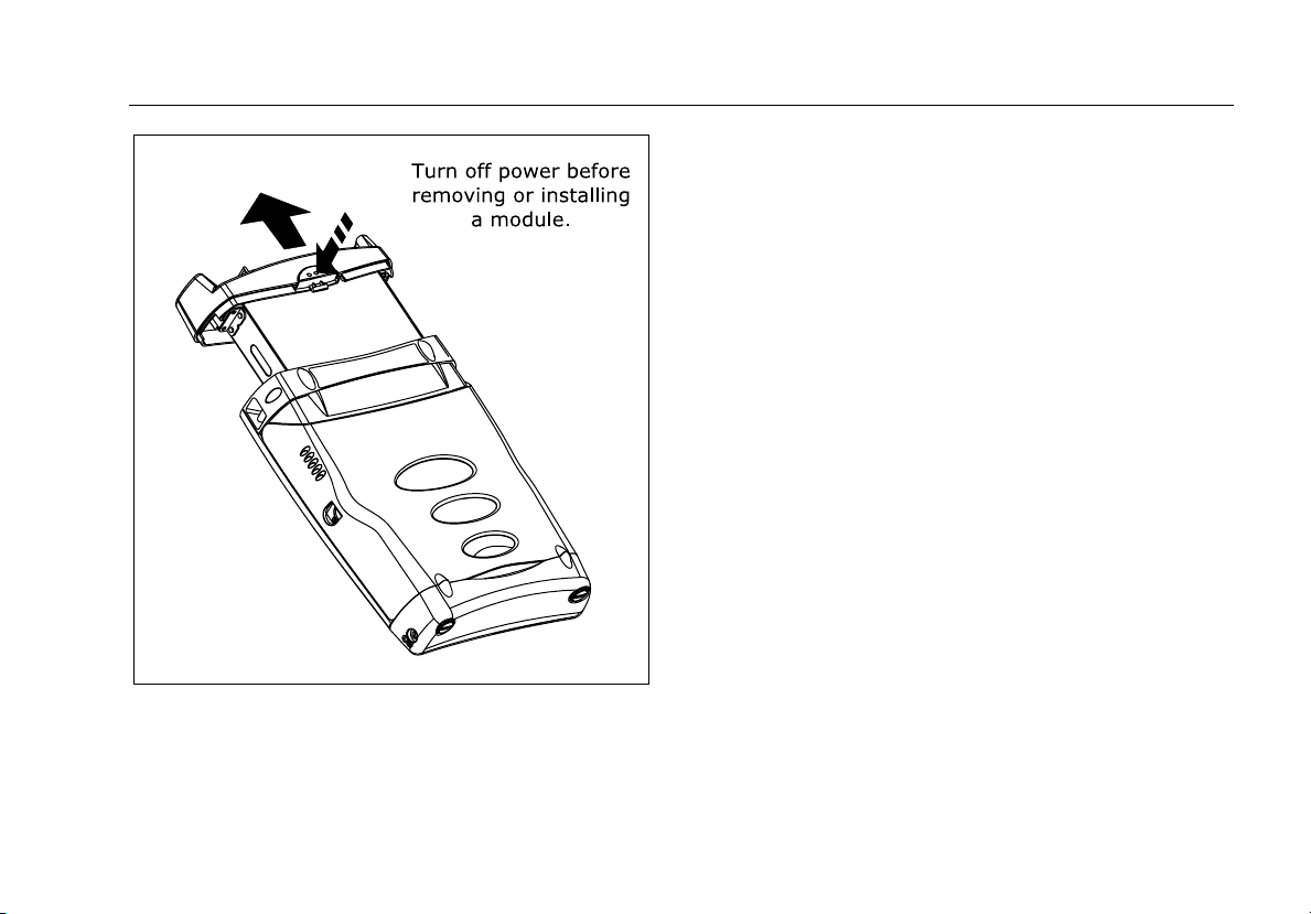
Removing and Installing the Module
The tester’s capabilities depend on which test module is
installed. Figure 1-2 shows how to remove the module.
WCaution
To avoid corrupting the tester's software,
always turn the tester off before removing or
installing the module.
Verifying Operation
The tester performs a basic self-test when you turn it on. If
the tester reports an error or does not turn on, refer to “If
Something Seems Wrong” in Chapter 11.
The tester shows the model number of the installed
module in the upper-right corner of the screen. If the
screen shows No Module Installed or Problem with
Module or The module needs a software update refer to
“If Something Seems Wrong” in Chapter 11.
1-10
Page 29
Getting Acquainted
Verifying Operation 1
ajt56f.eps
Figure 1-2. Removing the Module
1-11
Page 30
OF-500 OptiFiber Certifying OTDR
Technical Reference Handbook
Basic Features
The following sections describe the tester's basic features
and introduce the tester's menu system.
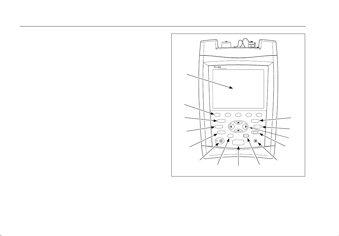
Front Panel Features
Figure 1-3 describes the tester’s front panel features.
1-12
A
N
M
L
F1
F2
F3
SETUP
FUNCTIONS
FIBER
INSPECTOR
HELP
TEST
K
J
I
Figure 1-3. Front Panel Features
H
F4 F5
ENTER
OPTIFIBER
SAVE
VIEW
RECORDS
EXIT
G
F
E
B
C
D
ajt12f.eps
Page 31

Getting Acquainted
Basic Features 1
A
LCD display with backlight and adjustable brightness.
B s: Saves test results on the removable memory
card or in internal memory.
I H: Shows a help topic related to the current screen.
To see the help index, press
H again.
J I: On/off key.
C v: Shows the test records saved on the memory
card or in internal memory.
D K N L M: Navigation keys let you move the cursor
or highlighted area on the screen and increment or
decrement alphanumeric values.
E e: Exits the current screen.
F J: Lets you adjust the display brightness.
G t: Selects the highlighted item on the screen.
H T: Starts the currently selected fiber test. The test
that will run is shown in the upper-left corner of the
display. To change the test, press
from the HOME screen or select a test from the
FUNCTIONS menu.
A Change Test
Figure 1-3. Front Panel Features (cont.)
K f: Activates the optional FiberInspector video
probe, which lets you inspect fiber endfaces and save
the images with test results.
L F: Shows a list of additional test, configuration,
and status functions.
M S: Shows the menus you use to configure the
tester.
N A B C D E: The five softkeys provide
functions related to the current screen. The current
functions are shown on the screen above the keys.
1-13
Page 32

OF-500 OptiFiber Certifying OTDR
Technical Reference Handbook
Side and Top Panel Features
Figure 1-4 describes the tester’s connectors and other
features on the side and top panels.
Figure 1-4. Side and Top Panel Features
ajt14f.eps
1-14
Page 33

Getting Acquainted
Basic Features 1
I
A Connector for the ac adapter. The LED turns on when the
adapter is connected to ac power.
OFTM-57xx: Connector for the visual fault locator.
J OTDR connector adapter (SC is standard). The LED
B USB port for uploading test reports to a PC and
downloading software updates from a PC to the tester.
See the LinkWare documentation for details on using the
USB port.
C Six-pin mini DIN connector for an optional external PS2
keyboard.
D Eight-pin mini DIN connector for the optional
FiberInspector video probe.
E Fan vents.
F RS-232C serial port for uploading test reports to a PC and
downloading software updates from a PC to the tester.
See the LinkWare documentation for details on using the
serial port.
lights when the laser is active.
K OFTM-5612B/5732: Loss/length output port (SC).
Transmits optical signals for loss/length tests.
L OFTM-5731/5732/5611B/5612B: Loss/length input
port with interchangeable connector adapter (SC is
standard). Receives optical signals for power
measurements and loss/length tests.
*
W
Never look directly into optical connectors.
Some sources produce invisible radiation that
can permanently damage your eyes.
Warning
M Laser safety label (shown below).
G Slot for the removable memory card. The LED lights when
the tester is writing to or reading from the memory card.
H Multimode (MM) or singlemode (SM) label for the module.
Figure 1-4. Side and Top Panel Features (cont.)
CAUTION
ajt72f.eps
1-15
Page 34

OF-500 OptiFiber Certifying OTDR
Technical Reference Handbook
The HOME Screen
The HOME screen shows important test and job settings
you might need to change to configure the tester for your
needs.
L
K
J
I
H
Figure 1-5. Home Screen for OTDR with Loss/Length Option
Figure 1-5 describes a typical home screen.
G
F
E
A
B
C
D
ajt13f.eps
1-16
Page 35

Getting Acquainted
Basic Features 1
A
Model number of the installed module.
B The current date and time.
I Action prompts. For most screens, this area prompts
you on what keys to press.
J Important test and job settings. To change these
C Owner’s logo. See “Changing the Logo on the HOME
Screen” on page 1-26.
D Battery status icon. For more information about the
battery, press F; then select Battery Status.
E Press E to see the hardware and software versions and
calibration dates for the tester and the installed module.
F Press D VFL to activate the visual fault locator.
settings, use KLMNto highlight a setting; then
t. Selecting TEST LIMIT or FIBER TYPE lets
press
you change the item. Selecting the limit’s or type’s
name lets you see that item’s settings. You may also
access the tester’s settings by pressing
S.
K The test mode, which determines what type of test
will run when you press T. The available modes
depend on which module is installed. To change the
test mode, press A Change Test.
G If the last test run was not saved, you can press
C Unsaved Result to see the test’s results.
L The name of the current screen.
H Press A Change Test to switch test modes. See K.
Figure 1-5. Home Screen for OTDR with Loss/Length Option (cont.)
1-17
Page 36

OF-500 OptiFiber Certifying OTDR
Technical Reference Handbook
Using the Setup Menus
To access the tester’s settings press S. Figure 1-6
introduces the SETUP menus.
C
Figure 1-6. The SETUP Screen
A
B
ajt17f.eps
1-18
Page 37

Getting Acquainted
Basic Features 1
A The settings available on the current tab.
Note
To see details about a setting, highlight the
setting; then press H.
B Use D Tab and E Tab to move among tabs on
the SETUP screen.
C Tabs for the setup menus:
• Job settings apply to the fiber installation you are
testing and are stored with saved test results. Use
these settings to identify the job site, set up cable ID
lists, and identify which end of the cabling you are
testing. See Chapter 2 for details.
• System settings let you localize the tester and set
other user preferences, such as the power down
timeout and camera type.
Figure 1-7. The Setup Screen (cont.)
• The Cable tab lets you select the type of fiber cable you
will test and define some cable characteristics for
loss/length tests. You can also change the index of
refraction if you do not want to use the default values.
Note
Select a fiber type before selecting a test limit. The
fiber type determines which test limits are available.
• The OTDR tab lets you select a test limit and wavelength
for OTDR tests and enable launch fiber compensation. You
can also change settings for Manual OTDR mode. See
Chapter 3 for details.
• The Loss/Length tab appears if the module includes the
loss/length option or power meter option (you can run loss
tests in Far End Source mode with the power meter
option). Use this tab to configure the loss/length test. See
Chapter 6 for details.
Different or additional tabs may be available depending on
the installed module.
1-19
Page 38

OF-500 OptiFiber Certifying OTDR
Technical Reference Handbook
Checking the Software and Hardware Versions
To see the tester’s software and hardware versions press
E Version Info. from the HOME screen.
The VERSION screen shows the software and hardware
versions and serial numbers of the tester and the installed
module.
The software version information includes the date the
software was compiled at the factory.
To determine if your tester needs a software update visit
the Fluke Networks website to see if an update is
available.
If "Unknown" is shown for the module software version
the module software is probably quite old. Update the
module software to the latest version.
The module information includes the date the module
last received calibration at a Fluke Networks service
center. The tester requires a traceable calibration at a
Fluke Networks service center once a year to ensure that it
meets or exceeds the published accuracy specifications.
Using the Online Help
When you press H, the tester shows a help topic that
relates to the current screen. Blue, underlined words are
links to other topics.
Note
The help files are stored in the mainframe
(rather than the module) and may describe
features not present in the installed module.
To go to a linked topic (blue, underlined words) use K N
to highlight the words; then press t.
To see an index of all help topics press
are in the help system.
Tip: The highlighted area cycles through the links on the
current screen if you continue to press the left or
right arrow key.
H any time you
1-20
Page 39

Getting Acquainted
Basic Features 1
To mark a topic for quick access later press A Set
Bookmark when the topic you want to mark is displayed.
You can place multiple bookmarks.
To go to a bookmarked topic press
while viewing help; then select the bookmark from the
list.
To go back to the previous topic press
B Go to Bookmark
C Back.
Overview of Memory Features
You can save results on a removable memory card or in
the tester's internal memory.
To set the location for saving tests press
CURRENT FOLDER on the Job tab.
To check the memory status press
Memory Status. Press A to switch between the memory
card and internal memory status.
See Chapter 9 for details about the tester's memory
features.
S then select
F; then select
Using the Memory Card
Figure 1-8 shows how to insert and remove a memory
card. You can use MultiMediaCard (MMC) or Secure
Digital (SD) memory cards in the tester.
WCaution
Never remove the memory card while the
memory card’s LED is on. Doing so can corrupt
the data on the card.
Press S; then select CURRENT FOLDER on the Job tab
to do the following:
• See the folders available on the memory card
• Change the destination for saved results. Use
M to select a folder name; then press t. You can
save results on the memory card or in the tester's
internal memory.
• Create a new folder on the memory card. Press A
New Folder. Enter a name in the NEW FOLDER NAME
box; then press
• Delete an empty folder on the memory card. Press
B Delete.
To format the memory card press
Format Memory Card.
s.
F; then select
L or
1-21
Page 40

OF-500 OptiFiber Certifying OTDR
Technical Reference Handbook
Using the Internal Memory
Internal memory lets you continue saving results if you
run out of memory card space. Internal memory is in the
mainframe (rather than in the module) and is retained
when you turn off the tester or remove the battery pack.
See Chapter 9 for more information on the internal
memory.
Using an External Keyboard
The keyboard jack on the right side of the tester accepts a
6-pin mini DIN (PS/2) plug. The tester accepts only the
characters available on its text editing screen. Figure 1-9
shows which keys you can use on the keyboard.
Note
You cannot use an external keyboard to enter
international characters.
The OptiFiber Product Manuals CD includes a full-size
function key reference diagram that you can print, cut
out, and attach to the keyboard.
1-22
Figure 1-8. Inserting and Removing
the Memory Card
ajt54f.eps
Page 41

Getting Acquainted
Basic Features 1
EXIT
F1
Esc F1 F2 F3 F4 F5 F6 F7 F8 F9 F10 F11 F12
Esc F1 F2 F3 F4 F5 F6 F7 F8 F9 F10 F11 F12
F2
#
F3
F4
F5
1 2 3 4 5 6 7 8 9 0 -
TEST
SETUP
*
Q W E R T Y U I O P
A S D F G H J
Shift
Z X C V B N M
K
L
, . /
FUNCTIONS
[ ]
:
FIBER
INSPECTOR
Del
Shift
SAVE
Backspace
Enter
VIEW
RECORDS
Home
PgUp
PgDn
End
ENTER
HELP
ajt18f.eps
Figure 1-9. Using an External Keyboard
1-23
Page 42

OF-500 OptiFiber Certifying OTDR
Technical Reference Handbook
Setting User Preferences
The following sections describe settings you may want to
change when you first start using the tester.
Changing the Date, Time, and Numeric Formats
To set the date and time:
1 Press
2 Use
3 Use N or K to highlight the field you want to
4 Press
To select a date, time, or numeric format:
1 Press S; then press E to select the System tab.
2 Use L to highlight DATE FORMAT, TIME FORMAT,
3 Use
S; then press E to select the System tab.
L to highlight DATE or TIME; then press t.
change; then use M or L to change the setting.
s when you are finished.
or NUMERIC FORMAT; then press t.
L to highlight the desired format; then press
t.
Changing the Length Units
1 Press S; then press E to select the System tab.
2 Use
3 Use
L to highlight LENGTH UNITS; then press t.
L to highlight the setting you want; then press
t.
Enabling or Disabling the Save Warning
If you do not save a test, it is deleted from temporary
memory when you run another test.
To enable or disable a warning that reminds you about
the unsaved test:
1 Press S; then press E to select the System tab.
2 Use L to highlight Enabled or Disabled; then press
t.
Adjusting the Display Brightness
Press J to see the brightness adjustment screen. Use K
N for coarse adjustments; use D and E for fine
or
adjustments. Press s when you are finished.
The setting is retained when you turn the tester off.
The brightness setting does not affect the battery life.
1-24
Page 43

Getting Acquainted
Setting User Preferences 1
Using the Power Down Timer
The power down timer turns off the tester after a selected
period of inactivity.
Halfway through the timer period, the tester beeps, the
screen dims, and the tester enters a low-power mode.
Thirty seconds before the timer reaches zero, the tester
beeps again to alert you that it is about to turn off.
Pressing any key restarts the timer.
If the timer is disabled, the screen dims after 30 minutes
of inactivity to help conserve battery power.
Note
The power down timer is inactive when the ac
adapter is connected or when the USB or RS-232
serial port is active.
1 Press
2 Press t. Use L to highlight the setting you want;
S; then press E to select the System tab.
then press t.
Enabling or Disabling the Beeper
To enable or disable the tones for key presses and testing
progress
1 Press
2 Use
3 Use L to highlight the setting you want; then press
S; then press E to select the System tab.
L to highlight AUDIBLE TONE; then press t.
t.
1-25
Page 44

OF-500 OptiFiber Certifying OTDR
Technical Reference Handbook
Changing the Logo on the HOME Screen
The tester’s HOME screen shows the Fluke Networks logo
by default.
To change the logo on the HOME screen:
1 Register your tester with Fluke Networks to receive a
registration key. See “Registration” on page 1-2 for
details.
2 Use a graphics application to create a graphic with
the following format:
• Dimensions: 240 x 60 pixels maximum.
• Colors: 128 colors maximum, with an indexed color
palette.
• File format: Save the graphic as an 8-bit bitmap file
(.bmp) or an 8-bit Portable Networks Graphic file
(.png).
Note
The graphics application may list 256 colors with
the 8-bit setting; however, if your graphic uses
only 128 or fewer colors, it should work in the
tester.
3 Press
4 On the OPTIFIBER OPTIONS screen, highlight
5 Enter the software key in the CUSTOM LOGO key
6 Connect the tester to the PC via the serial or USB
7 In LinkWare select Utilities > OptiFiber Utilities >
8 Restart the tester to see the new logo.
To restore the Fluke Networks logo, select Utilities >
OptiFiber Utilities > Restore Default Logo; then restart the
tester
F; then select Enable OptiFiber Options.
CUSTOM LOGO; then press
box; then press
port.
Custom Logo. Locate and select the .bmp or .png
logo file; then click Open.
If the logo’s format is not valid, the tester deletes
the logo and uses the default logo.
s.
t.
Note
1-26
Page 45

Getting Acquainted
Enabling Software Options 1
Enabling Software Options
To see the options available with the version of software
installed in the tester press F, highlight Enable
OptiFiber Options; then press t. Additional options
may be available with software updates.
To see details about the available options press
the OPTIFIBER OPTIONS screen.
To enable an option contact Fluke Networks to get a
registration key; then select the option on the OPTIFIBER
OPTIONS screen to enter the key.
H from
About LinkWare and LinkWare Stats Software
The LinkWare Cable Test Management software
included with your tester lets you do the following:
• Upload test records to PC.
• View test results.
• Add ANSI/TIA/EIA-606-A administration information
to records.
• Organize, customize, and print professional-quality
test reports.
• Update the tester’s software.
Details about using LinkWare software are provided in
the LinkWare Getting Started Guide and the online help
available under Help on the LinkWare menu.
Updates to LinkWare software are available on the Fluke
Networks website.
The LinkWare Stats Statistical Report option for LinkWare
software provides statistical analysis of cable test reports
and generates browsable, graphical reports. LinkWare
software includes a demo version of LinkWare Stats.
Contact Fluke Networks or visit the Fluke Networks
website for more information on LinkWare Stats.
1-27
Page 46

OF-500 OptiFiber Certifying OTDR
Technical Reference Handbook
1-28
Page 47

Chapter 2
Getting Started Testing Fiber
Safety Information
Table 2-1 shows the international electrical symbols used
on the tester or in this manual.
Table 2-1. International Electrical Symbols
X
W
*
Warning: Risk of fire, electric shock, or personal
injury.
Warning or Caution: Risk of damage or
destruction to equipment or software. See
explanations in the manuals.
Warning: Class 1 laser (OUTPUT port). Risk of eye
damage from hazardous radiation.
Do not put products containing circuit boards
~
into the garbage. Dispose of circuit boards in
accordance with local regulations.
2-1
Page 48

OF-500 OptiFiber Certifying OTDR
Technical Reference Handbook
*
W
Warning
To avoid possible eye damage caused by
hazardous radiation and to avoid possible fire,
electric shock, or personal injury:
• Never look directly into optical connectors. Some
sources produce invisible radiation that can
permanently damage your eyes.
• Never run any tests that activate the tester’s
outputs unless a fiber is attached to the output.
• Do not open the case; no user-serviceable parts
are inside.
• Do not modify the tester.
• Do not use magnification to view the optical
outputs without proper filtering.
• Use of controls, adjustments, or procedures not
stated herein might result in hazardous
radiation exposure.
• Use only ac adapters approved by Fluke
Networks for use with the OptiFiber tester to
charge the battery or power the tester.
2-2
Page 49

Getting Started Testing Fiber
Safety Information 2
• Do not use the tester if it is damaged. Inspect
the tester before use.
• If this equipment is used in a manner not
specified by the manufacturer, the protection
provided by the equipment may be impaired.
WCaution
To avoid damaging the tester or cables under
test and to avoid data loss:
• Always turn the tester off before removing or
installing a module.
• Never connect the OTDR port to an optical
source. Doing so can damage the OTDR receiver.
• Never connect the tester to an active network,
except when using the power meter. Doing so
causes unreliable test results and can disrupt
network operations.
• If the tester shows an error because the power
reading is too high, immediately disconnect the
source from the tester. The tester is not
designed for measuring higher power levels,
such as produced by CATV, optical amplifiers,
and cellular systems.
• Avoid touching reflective surfaces (such as
metal) to the end of a fiber cable plugged into
the OTDR when the OTDR is operating. An open
fiber connector endface has about a 4%
reflection. Holding a reflective surface near the
connector endface may cause much greater than
a 4% reflection, which may damage the
photodetector in the OTDR.
• Use proper cleaning procedures to clean all fiber
connectors before every use. Neglecting this
step or using improper procedures can cause
unreliable test results and may permanently
damage the connectors.
• Use a Fluke Networks FiberInspector Video
Microscope to periodically inspect the OTDR and
loss/length option’s OUTPUT connectors for
scratches and other damage.
• Read the instructions for splice machines before
using the OTDR to monitor splicing procedures.
The OTDR can interfere with the light injection
detection techniques used by some splicers.
• To avoid unreliable test results, connect the ac
adapter or replace the battery as soon as the
low battery indication appears.
2-3
Page 50

OF-500 OptiFiber Certifying OTDR
Technical Reference Handbook
• You may use a PC to move or copy test record
(.tst) files from a memory card, but do not
rename the .tst files. Doing so may result in loss
of data.
• Never remove the memory card while the
memory card’s LED is on. Doing so can corrupt
the data on the card.
Cleaning and Inspecting Fiber Connectors and Adapters
Always clean and inspect fiber connectors before making
connections. Use 99 %-pure isopropyl alcohol and opticalgrade wipes or swabs to clean fiber connectors as follows:
WCaution
See Chapters 3 and 6 for instructions on cleaning
the tester's OTDR and loss/length connectors.
• Connector ends: Wipe the end of the ferrule with a
swab or wipe lightly moistened with alcohol. Dry
with a dry swab or wipe.
• Bulkhead adapters:
1 Touch the tip of a lint-free foam swab to an
alcohol-soaked cleaning pad.
2 Push the swab into the adapter; twist it around 3
to 5 times against the endface, then remove and
dispose of the swab.
3 Dry the endface with a dry, lint-free swab by
twisting it around in the adapter 3 to 5 times.
• Inspect connectors with a fiber microscope, such as
the Fluke Networks FiberInspector Video Probe
before making connections. See Chapter 5 or the
tester’s online help for details.
• Periodically clean fiber adapters with a swab and
alcohol. Dry adapters with a dry swab before use.
• Always cover unused connectors with dust caps or
plugs. Clean dust plugs periodically with a swab or
wipe and alcohol.
2-4
Page 51

Getting Started Testing Fiber
Testing Your Reference Test Cords and Launch Fiber 2
Testing Your Reference Test Cords and Launch Fiber
You should test your reference test cords and launch fiber
before each job. Use another set of known-good cords to
set a reference and run an Autotest on each patch cord
and launch fiber. Use Smart Remote mode to test two
cords at a time, or Loopback mode to test one cord.
You should also use a fiber microscope, such as the
FiberInspector video probe, to inspect the reference test
cord and launch fiber connectors for damage at least once
a day.
2-5
Page 52

OF-500 OptiFiber Certifying OTDR
Technical Reference Handbook
General Test Settings
The following sections describe settings you will usually
need to make before running a test:
• Test mode
• Fiber type
• Test limit
• Job settings
You may also want to change the index of refraction if
you do not want to use default values.
Information on settings specific to a particular test is
provided in the chapter for that test. For information on
setting user preferences, see Chapter 1.
Selecting a Test Mode
The test mode determines what type of test will run when
you press T. The mode is shown in the upper-left
corner of the HOME screen. To change the test mode,
A Change Test; then select a test from the menu.
press
Selecting a Fiber Type
Note
Select a fiber type before selecting a test limit.
The fiber type determines which test limits are
available.
To select a fiber type, press
on the Cable tab.
The selected fiber type determines which test limits are
available, the default index of refraction, and other values
used for testing.
S; then select FIBER TYPE
2-6
Page 53

Getting Started Testing Fiber
General Test Settings 2
You can also create custom fiber types based on specific
needs. Custom types are marked with asterisks (*) in the
fiber type list.
To create a custom fiber type, press
Custom Test Limit; then press C Edit Fiber Types. See
Chapter 10 for details.
F, select Edit
Viewing Fiber Properties
To see the properties associated with a fiber type, do the
following:
1 Press
2 Select FIBER TYPE.
3 Highlight a fiber type; then press
For details on fiber properties, see Chapter 10.
S; then select the Cable tab.
A View Fiber
Type.
Selecting a Test Limit
Note
Select a fiber type before selecting a test limit.
The fiber type determines which test limits are
available.
The tester offers generic and industry-standard test limits
for testing fiber cable. The tester uses the selected limit to
produce PASS/ FAIL results.
To select a test limit, press S, select a test’s tab; then
select TEST LIMIT. Each test’s tab shows only the limits
that include the selected fiber type and parameters for
that test.
Generic limits, such as General Fiber and Document only,
let you run tests when no industry-standard limit applies
and you do not want to create a custom limit. The
Document only limit does not produce PASS/FAIL results.
Custom limits you create are marked with asterisks (*). To
create a custom limit, press
Test Limit. See Chapter 10 for details.
F; then select Edit Custom
2-7
Page 54

OF-500 OptiFiber Certifying OTDR
Technical Reference Handbook
Viewing Test Limits
To see the values of a test limit that includes the fiber
type selected on the Cable tab, do the following:
1 Press
2 Select TEST LIMIT.
3 Highlight a limit on the SET TEST LIMIT screen; then
S; then select a test’s tab.
press
A View Limit.
If the Test Limit or Fiber Type is Not Valid with the Test
• The fiber type was changed on the Cable tab in
Setup, and the current test limit does not include the
fiber type. Select a different test limit.
• The fiber type or test limit is missing a wavelength
the test uses. For example, you are trying to run a
dual-wavelength OTDR test, but the fiber type or
limit does not include both wavelengths. Select a
different fiber type or test limit.
• The installed module does not support the selected
fiber type or test limit. For example, a singlemode
fiber type is selected, but a multimode module is
installed. Select a different fiber type or test limit or
install a different module.
• The test limit does not include parameters for the
type of test you are trying to run. For example, you
are trying to run an OTDR test, but only loss/length
limits are defined in the selected test limit. Select a
test limit that includes limits for the test you want to
run.
If you selected a custom fiber type or limit, you could also
edit the fiber type or limit to make it valid with the test.
See Chapter 10 for details.
Entering Job Settings
Job settings let you identify and organize the test results
you save. To access the job settings press S. Table 2-2
describes the job settings.
See “Tutorial: Preparing to Save Tests” on page 2-11 for
examples of how to configure the job settings.
2-8
Page 55

Getting Started Testing Fiber
General Test Settings 2
Table 2-2. Job Settings
Setting Description
COMPANY The customer name, job site, job work order, or other job identifier.
OPERATOR The name of the OptiFiber user.
CURRENT FOLDER The destination for tests you save. You can save tests in a folder on the memory card or in the
tester's internal memory. Selecting CURRENT FOLDER also lets you create a new folder on the
memory card. You cannot create folders in internal memory.
END 1, END 2 Names you assign to the ends of the cabling. The names are saved with test records and also
appear on ChannelMap diagrams.
THIS END The cable end where the tester is located. Based on this setting, the tester labels OTDR,
ChannelMap, FiberInspector, and power meter results as END 1 or END 2 to indicate which end
of the cabling you tested. Loss/length results are labeled END 1-2 or END 2-1.
AUTO SEQ TEMPLATE The name of the pattern selected for the list of sequential fiber IDs. See “Creating a List of
Sequential IDs” on page 2-24 for details.
START ID, END ID The first and last IDs in the auto sequence list. See “Creating a List of Sequential IDs” on page
2-24 for details.
2-9
Page 56

OF-500 OptiFiber Certifying OTDR
Technical Reference Handbook
Changing the Index of Refraction
The index of refraction is the ratio of the speed of light in
a vacuum to the speed of light in a fiber. The tester uses
the index of refraction to determine fiber length.
You can change the index of refraction on the Cable tab
in Setup.
When MANUAL CABLE SETTINGS on the Cable tab is
disabled, the tester uses the n values specified in the
selected fiber type.
When MANUAL CABLE SETTINGS is enabled, the tester
uses the n values you enter.
The n values defined in the fiber types are suitable for
most applications. Minor differences between the tester's
n and a fiber's actual n usually do not make enough
difference in length to fail a fiber.
You may want to change the index of refraction if
• The customer wants you to use a specific n value for
the job.
• The cable's fibers are longer than its jacket, and you
need to precisely locate a point on the cable (such as
a fault). In this case, adjust n until the measured
length matches a known length of fiber.
Increasing n decreases measured length.
Note
If you try to enter a value outside the valid
range for n, the tester shows N/A for the value.
The valid range is 1.1 to 1.71 inclusive.
To use the default n values specified in the selected fiber
type, set MANUAL CABLE SETTINGS to Disabled.
2-10
Page 57

Getting Started Testing Fiber
Tutorial: Preparing to Save Tests 2
Tutorial: Preparing to Save Tests
The tutorial in this section guides you through setting up
the tester to save tests.
Step 1: Creating a List of Sequential Fiber IDs
This step assumes the following scenario:
• You will be testing 12 cables in two patch panels:
cables 1 through 6 in panel A and cables 1 through 6
in panel B.
• Both panels are located in telecommunications closet
A on the third floor of the building.
• Your fiber IDs will follow the ANSI/TIA/EIA-606-A
standard for horizontal links. See “About
ANSI/TIA/EIA-606-A Fiber IDs” on page 2- 25 for
details.
1-1 Press
1-2 On the AUTO SEQUENCE screen, press
S; then select AUTO SEQ TEMPLATE on
the Job tab.
AChange
Template; then select Horizontal.
1-3 On the AUTO SEQUENCE screen press
transfer the default pattern into the START ID and
STOP ID.
1-4 On the AUTO SEQUENCE screen press
Use the softkeys, K N ML, and t to change
the default ID to 03A-A01 in the CURRENT START ID
box. Press
1-5 On the AUTO SEQUENCE screen press
Use the softkeys and K NML to change the
default ID to 03A-B06 in the CURRENT START ID box.
Press
1-6 Press
sequential fiber IDs: 03A-A01 through 03A-B06. If
the tester beeps instead of showing the list, see
“Solving Problems with Fiber ID Lists” on page 2-27.
1-7 Press
1-8 Press s when you are finished setting up the list.
The list is saved in the mainframe (not on the
memory card or in the module).
s when you are finished.
s when you are finished.
E Sample List. You should see a list of 12
e to leave the sample list.
D Default to
B Edit Start.
C Edit Stop.
2-11
Page 58

OF-500 OptiFiber Certifying OTDR
Technical Reference Handbook
Step 2: Setting Up a Job Folder
You can organize test results on the memory card by
setting up a folder for each job, as follows:
2-1 Insert a formatted memory card into the tester.
2-2 Press
2-3 Press
2-4 Press t to select the new folder as the current
S; then select CURRENT FOLDER on the
Job tab.
A New Folder. Use the softkeys, K NML,
and t to enter a folder name into the NEW
FOLDER NAME box. Figure 2-1 describes the text
editing screen.
s when you are finished.
Press
folder.
Step 3: Entering the Operator Name
For this tutorial you will enter your name as the operator.
3-1 Press
3-2 Use the softkeys,
S; then select OPERATOR on the Job tab.
K NML, and t to enter your
name into the OPERATOR box. Press s when
you are finished.
Step 4: Identifying the Cabling Ends
For the OTDR and Loss/Length testing tutorials in this
chapter, you will save test results from both ends of the
cabling. To identify the test directions in the saved
results, enter END information on the Job tab as follows:
4-1 On the Job tab select END 1. Use the softkeys,
NML
box. Press s when you are finished.
4-2 On the Job tab select END 2. Use the softkeys,
, and t to enter CLOSET into the END 1
K
K N
ML, and t to enter WORK AREA into the END
2 box. Press s when you are finished.
4-3 On the Job tab, verify that THIS END is set to END 1.
Change it to END 1 if necessary.
Step 5: Setting the Save Warning
If you do not save a test, it is deleted from temporary
memory when you run another test. To enable or disable
a warning that reminds you to save the test, do the
following:
5-1 On the System tab, select SAVE WARNING.
5-2 Use
LM to highlight Enabled or Disabled; then
t.
press
2-12
Page 59

Getting Started Testing Fiber
Tutorial: Preparing to Save Tests 2
A The characters available for use.
3
2
To select a character to enter in the text box, use
LMKN to highlight the character; then press H.
The character is entered to the left of the cursor.
B The text you are entering.
1
C The cursor. Use A B to move the cursor.
D Moves the cursor to the left until it wraps back around
to the end of the text.
E Decreases or increases the character at the cursor by
one position in the character list.
4
5 6
ajt65f.eps
Figure 2-1. Using the Text Editing Screen
2-13
F Deletes the character to the left of the cursor.
Tip: You can use an external keyboard to edit text (except
international characters). See Chapter 1.
Page 60

OF-500 OptiFiber Certifying OTDR
Technical Reference Handbook
Tutorial: Running an OTDR Test
The tutorial in this section familiarizes you with the tester
by guiding you through the following tasks:
• Using the tester’s menu system
• Connecting the tester to a cable
• Running an OTDR test
• Viewing the results in several levels of detail
• Saving bi-directional test results
Required Equipment
• OptiFiber tester set up as follows:
¾ Multimode module installed
¾ Charged battery attached or the ac adapter
connected
¾ Job settings configured as follows (see the
tutorial “Preparing to Save Tests” on page 2-11
for configuration steps):
• START ID and STOP ID set to 03A-A01 and
03A-B06
• A job folder with any name created on the
memory card
• Your name as the operator
• END 1 set to CLOSET; END 2 set to WORK
AREA
• THIS END set to END 1
• Fiber cabling to test: 50 m to 2 km (165 ft to 6500 ft)
of multimode fiber. If possible, select cabling that
has a connector somewhere along its length.
• A launch fiber that matches the type of cable you
will test
• Fiber cleaning supplies
2-14
Page 61

Getting Started Testing Fiber
Tutorial: Running an OTDR Test 2
Step 1: Selecting Auto OTDR Mode
On the HOME screen, verify that Auto OTDR appears in
the upper-left corner of the screen. If it does not, press
A Change Test; then select Auto OTDR.
Step 2: Selecting a Fiber Type and Test Limit
2-1 Press S; then press D Tab to select the Cable
tab.
2-2 Use
2-3 Use LM to highlight the type of fiber you will
2-4 On the SETUP screen press
LM to highlight FIBER TYPE; then press t.
test; then press t to select the fiber type.
E Tab to select the
OTDR tab. If TEST LIMIT is already set to
Document only, go to step 3.
2-5 Press
2-6 Use LM to highlight Document only; then press
t to see the available test limits.
t to select the limit.
Step 3: Selecting a Wavelength
3-1 From the SETUP screen, press E Tab to select the
OTDR tab.
3-2 Change WAVELENGTH to Dual 850/1300 nm.
Step 4: Testing in the First Direction
4-1 Clean all fiber connectors.
4-2 Connect the launch fiber to the tester and to the
cabling. Figure 2-2 shows these connections and
typical features on an OTDR trace.
4-3 Press
T.
See Chapter 3 for details on the OTDR Port
Connection Quality gauge shown on the OTDR
TESTING screen.
2-15
Page 62

OF-500 OptiFiber Certifying OTDR
Technical Reference Handbook
2-16
Figure 2-2. Typical OTDR Connections and Trace Features
ajt21f.eps
Page 63

Getting Started Testing Fiber
Tutorial: Running an OTDR Test 2
Step 5: Viewing the Results
The tester offers the following views of OTDR test results:
• The SUMMARY screen, shown when the test is
finished, tells you if the cabling passed or failed
based on the selected test limits.
• To see the OTDR trace, press
2-2 shows some features of a typical OTDR trace.
• To see a table of the events on the cabling, press
A View Trace. Figure
B View Events.
See Chapter 3 for details on OTDR results.
Step 6: Saving Results from the First Direction
6-1 Press s.
6-2 If the tester shows a text editing screen, press
Pick ID to access the fiber ID list you configured.
6-3 If the UNUSED AUTO SEQUENCE IDs list is not
showing, press
6-4 The tester highlights the first unused ID in the
UNUSED AUTO SEQUENCE IDs list. Press s to
save the test with this ID (03A-A01).
C Auto Seq IDs.
A
Step 7: Testing in the Second Direction
7-1 On the Job tab in Setup, change THIS END to END 2.
7-2 Clean the connector at the other end of the cabling,
connect the launch fiber to the connector; then press
T.
Step 8: Saving Results from the Second Direction
8-1 Press s.
8-2 Press B Current Folder IDs to see the IDs you have
already used.
8-3 Select the ID 03A-A01; then press s. The tester
adds the results from the second direction to the test
record.
This concludes the tutorial on using the OTDR. For more
information on using the OTDR, see Chapter 3.
2-17
Page 64

OF-500 OptiFiber Certifying OTDR
Technical Reference Handbook
Tutorial: Running a Loss/Length Test
This section familiarizes you with the basic operation of
the loss/length option by guiding you through a
loss/length test in Smart Remote mode.
Required Equipment
• One OptiFiber tester set up as follows:
¾ OFTM-5612B or OFTM-5732 module installed
¾ Connector adapter installed on the tester's
INPUT port. Match the connectors on the fiber
under test.
¾ Charged batteries attached or the ac adapters
connected
¾ Job settings configured as described in the
tutorial “Preparing to Save Tests” on page 2-11
• A second OptiFiber tester set up like the first one, or
a DTX Smart Remote with a fiber module for the
correct wavelength and the correct connector
adapter installed
• Two lengths of fiber cabling or a length of duplex
cabling to test
• Two known-good duplex reference test cords of the
same fiber type as the cabling to be tested. See
Figures 2-3 and 2-4 to determine the connector types
you will need.
• For testing multimode fiber, two mandrels of the
correct size
• Fiber cleaning supplies
Step 1: Selecting Loss/Length Test Mode
On the HOME screen of both testers, verify that LOSS
LENGTH appears in the upper-left corner of the screen. If
it does not, press A Change Test then select
Loss/Length.
Step 2: Selecting a Fiber Type
Do the following on the tester you will use to initiate
tests (the main tester):
2-1 Press
2-2 Use
2-3 Use
S; then press D Tab to select the Cable
tab.
LM to highlight FIBER TYPE; then press t.
LM to highlight the type of fiber you will
test; then press
t to select the fiber type.
2-18
Page 65

Getting Started Testing Fiber
Tutorial: Running a Loss/Length Test 2
Step 3: Configuring the Loss/Length Test
Do the following on the tester you will use to initiate
tests (the main tester) and on the remote tester where
indicated:
3-1 From the SETUP screen, press E Tab to select the
Loss/Length tab.
3-2 Press
3-3 Use
t to see the available test limits.
LM to highlight Document only; then press
t to select the limit.
3-4 Use
3-5 Use
LM to highlight REMOTE END SETUP; then
press t.
LM to highlight Smart Remote; then press
t.
If a message about setting the reference appears,
press
B No. You will set the reference in Step 4.
3-6 Use
3-7 Use
LM to highlight THIS UNIT; then press t.
LM to highlight Main; then press t.
3-8 Use
LM to highlight BI-DIRECTIONAL; then press
t.
3-9 Use
3-10 On the remote unit’s Loss/Length tab set REMOTE
LM to highlight Disabled; then press t.
END SETUP to Smart Remote and THIS UNIT to
Remote.
Step 4: Setting the Reference
4-1 Clean the tester's and source's OUTPUT connectors
and the reference test cord connectors.
4-2 Press
4-3 Connect the main and remote testers as shown on
4-4 On the VIEW REFERENCE screen press
F. Use LM to highlight Set Loss/Length
Reference; then press t.
the SET REFERENCE screen and in Figure 2-3; then
press t.
C OK. (You
do not need to enter reference test cord lengths for
this tutorial.)
2-19
Page 66

OF-500 OptiFiber Certifying OTDR
Technical Reference Handbook
2-20
Figure 2-3. Smart Remote Mode Reference Connections
ajt05f.eps
Page 67

Getting Started Testing Fiber
Tutorial: Running a Loss/Length Test 2
Step 5: Running the Test
5-1 Make the connections for a Smart Remote mode
test, as shown in Figure 2-4. Connect the main unit
to the cabling end identified as END 1 on the Job
tab.
5-2 Press
T.
Step 6: Viewing the Results
The tester offers the following views of loss/length test
results:
• The SUMMARY screen, shown when the test is
finished, tells you if the cabling passed or failed
based on the selected test limits.
• To see more details about the cabling, press
View Results.
See Chapter 6 for details on loss/length results.
A
Step 7: Saving the Results
Note
The tester saves Smart Remote test results in
two separate records. One record is used for
each fiber.
7-1 Press s.
7-2 If the tester shows a text editing screen, press A
Pick ID to access the fiber ID list you configured.
7-3 The tester highlights the first unused ID in the
UNUSED AUTO SEQUENCE IDs list. Press s to
save the results from one fiber.
7-4 Press s again to save the results from the second
fiber, using the next ID in the list.
This concludes the tutorial on using the loss/length
option. See Chapter 6 for additional information on the
loss/length option.
2-21
Page 68

OF-500 OptiFiber Certifying OTDR
Technical Reference Handbook
2-22
Figure 2-4. Smart Remote Mode Test Connections
ajt08f.eps
Page 69

Getting Started Testing Fiber
Fiber ID Options 2
Fiber ID Options
You can create or select fiber IDs as follows:
• You can create an ID after you press s. You can
also highlight a used or unused ID in a list; then press
t to edit it into a new ID. The next time you press
s, the tester increments the last character of the
ID you created (the auto increment feature).
• You can create a list of sequential fiber IDs by
configuring a template on the Job tab in Setup.
Select the IDs from the AUTO SEQ IDs list after you
press s.
• You can create ID lists in LinkWare software; then
download them to the tester. Select the IDs from the
DOWNLOAD IDs list after you press
• After you press
assigned to a record stored in the current folder. This
lets you overwrite existing results or add new results
to an existing record. Select the ID from the IDs IN
CURRENT FOLDER list after you press
s, you can use an ID already
s.
s.
Using the Auto Increment Feature
The auto increment feature increments the last
alphanumeric character in the fiber ID you enter. For
example, if you save a test with the ID “A0”, the tester
increments the ID to “A1” the next time you save a test.
As you save more tests, the ID increments from “A1”
through “A9”; then back to “A0”. Consecutive digits
increment from right to left, but other characters do not.
To use this feature, do the following:
1. Run a test; then press
2. Enter a fiber ID in the SAVE RESULT IN FIBER ID: box.
You may need to press
3. Press
4. The next time you press s, the incremented fiber
s again.
ID appears in the editing box. Press s again to
use the ID.
s.
A Edit ID to see this box.
2-23
Page 70

OF-500 OptiFiber Certifying OTDR
Technical Reference Handbook
Creating a List of Sequential IDs
The tester includes templates for creating a list of
sequential fiber IDs. Three of these templates meet the
ANSI/TIA/EIA-606-A standard for documenting cabling
installations, as summarized in the next section. A fourth
template lets you create your own ID pattern.
Letters and numbers in sequential IDs increment from
right to left. Special characters, accented letters, and
matching letters do not increment. For example, the
following start and stop IDs could be used for testing the
cabling in two rooms where each room has three cable
drops:
Start ID: ROOM A DROP#1
Stop ID: ROOM B DROP#3
These IDs produce the following ID list:
ROOM A DROP#1
ROOM A DROP#2
ROOM A DROP#3
ROOM B DROP#1
ROOM B DROP#2
ROOM B DROP#3
To create a list of sequential IDs, do the following:
1 Select AUTO SEQ TEMPLATE from the Job tab in
Setup, press
template.
2 Press D Default to transfer the pattern to the
START ID and STOP ID.
3 Press
appropriate characters into the start and stop IDs.
Press s when you are finished editing each ID.
4 To preview the list, press
5 Press
The sequential ID list is stored in the mainframe (not on
the memory card or in the module).
To use an ID from the list, do the following:
1 Run a test; then press
2 Press
need to press A Pick ID first.
3 Highlight an ID; then press
A Change Template; then select a
B Edit Start or C Edit Stop to enter
E Sample List.
s when you are finished.
s.
C Auto Seq IDs to select the list. You may
s.
2-24
Page 71

Getting Started Testing Fiber
Fiber ID Options 2
About ANSI/TIA/EIA-606-A Fiber IDs
The following sections give basic examples of the 606-A
IDs. For detailed information, including ID formats for
other elements in cabling installations, contact the TIA to
purchase a copy of the 606-A standard.
The examples use the following abbreviations:
• f = floor number
• s = telecom room letter
• a = patch panel letter
• n = For a horizontal link: port number
For a backbone: backbone cable letter or number
• d = copper pair or fiber strand number in backbone
cable
• b = building
Horizontal Link Identifier
Horizontal links run between telecommunications closets
and work areas.
Format: fs-an
Example: 11C-D32
The link tested was on floor 11 in telecom room C, patch
panel D, port 32.
Backbone Cable Identifier
Backbone cables run between telecommunication closets,
usually on different floors.
Format: fs1/fs2-n.d
Example: 01B/5C-D.10
The fiber tested is in the backbone cable that runs
between floor 1, telecom room B and floor 5, telecom
room C. The backbone cable is cable D. The fiber tested is
fiber 10 in backbone cable D.
2-25
Page 72

OF-500 OptiFiber Certifying OTDR
Technical Reference Handbook
Campus Cable Identifier
Campus cables are backbone cables that run between
buildings.
Format: [b1-f s1]/[b2-fs2]-n.d
Example: LBRY-01A/AUD-01A-5.16
The cable tested is in the backbone cable that runs
between the library (LBRY), floor 1, telecom room A and
the auditorium (AUD), floor 1, telecom room A. The
backbone cable is cable 5. The fiber tested is number 16 in
backbone cable 5.
Using Downloaded Fiber IDs
Use LinkWare software to create and download ID lists
from a PC to the tester.
Downloaded ID lists are associated with a folder name
you select when you download the list from a PC, but are
saved in the tester’s internal memory.
To use downloaded IDs, do the following:
1 Verify that the current folder has the same name as
the folder selected when the list was downloaded to
the tester. Change the current folder or create a new
folder with the correct name, if necessary.
2 Run a test; then press
3 Press D Download IDs to select the list. You may
need to press A Pick ID first.
4 Highlight an ID; then press
s.
s.
Solving Problems with Fiber ID Lists
Table 2-3 gives solutions to some typical problems you
may have with fiber ID lists.
2-26
Page 73

Getting Started Testing Fiber
Fiber ID Options 2
Table 2-3. Solving Problems with Fiber ID Lists
Problem Solutions
The ID sequence is invalid. Verify that the types of characters in each position match between the start and stop IDs.
For example, using the letter “O” as the third character in the start ID and the number
“0” as the third character in the end ID causes an error.
Verify that you are not trying to use accented characters as incrementing characters. You
may use accented characters in IDs, but they must match between the start and stop IDs.
Verify that the start and stop IDs have the same numbers of characters.
Verify that the START and STOP IDs do not generate a sequence with more than 3000 IDs.
When you press s, you
cannot find the ID list.
After you press s, press A Pick ID; then press the appropriate softkey to see the list.
You can access downloaded IDs only if the name of the current folder matches the folder
name selected when the list was downloaded from the PC. Downloaded ID lists are
associated with a folder name, but are saved in internal memory. Switch to the correct
folder or create a new folder with the correct name.
2-27
Page 74

OF-500 OptiFiber Certifying OTDR
Technical Reference Handbook
Adding Comments to Test Results
After you run a test, you can press D Edit Comment to
add a comment to the results. You can select predefined
comments or create a new comment.
The comment list is stored in the mainframe, not in the
module or on a memory card.
To edit or create a comment press
EDIT COMMENT screen.
To add a predefined comment to the list press
Comment on the EDIT COMMENT screen; then press A
New Comment.
To select a predefined comment press
on the EDIT COMMENT screen.
Press
s when you finished editing or selecting a
comment.
2-28
E Edit Text on the
D Pick
D Pick Comment
Page 75

*
W
Warning
Read the safety information at the beginning of
Chapter 2 before using the OTDR.
Setting Up for OTDR Testing
For information on configuring the tester's job settings,
such as fiber IDs and folders for saving test results, see
“General Settings” in Chapter 2.
For information on setting user preferences, such as
length units and numeric formats, see “Setting User
Preferences” in Chapter 1.
Chapter 3
Using the OTDR
3-1
Page 76

OF-500 OptiFiber Certifying OTDR
Technical Reference Handbook
Cleaning the OTDR Connector
Note
Typically, the OTDR connector requires cleaning
only if it has been touched.
Use a dry, optical-grade wipe to clean the OTDR
connector. Figure 3-1 shows how to remove the OTDR
adapter to access the connector ferrule.
The OTDR port connection quality screen helps you
determine when the OTDR connector needs cleaning. See
page 3-14.
If the connector is very dirty, wipe the end of the ferrule
with an optical-grade wipe lightly moistened with 99 %pure isopropyl alcohol. Dry with a dry wipe.
3-2
Figure 3-1. Cleaning the OTDR Connector
ajt71f.eps
Page 77

Using the OTDR
Setting Up for OTDR Testing 3
Selecting Auto or Manual OTDR Mode
Note
You should use Auto OTDR mode when
certifying cabling with the OTDR.
From the HOME screen, press
Auto OTDR or Manual OTDR from the popup menu.
You can also switch between test modes by selecting Auto
OTDR or Manual OTDR from the FUNCTIONS menu.
In Auto OTDR mode, the tester automatically selects
settings based on the length and overall loss of the
cabling. This mode is the easiest to use, provides the most
comprehensive view of the events on the cabling, and is
the best choice for most applications.
Manual OTDR mode lets you change settings to optimize
the OTDR for displaying specific events. See “Using
Manual OTDR Mode” on page 3-46 for details.
A Change Test. Select
Tip: To see the settings used for an OTDR test, press
View Details on the OTDR SUMMARY screen; then
press A OTDR Settings. The settings used may be
slightly different from the nominal values selected on
the OTDR tab.
C
About Launch and Receive Fibers
Launch and receive fibers let the tester measure the loss
and reflectance of the first and last connectors in the
cabling, and include those connectors in ORL (optical
return loss) measurements. Without launch and receive
fibers, no backscatter is available before the first
connector and after the last, so the tester cannot measure
the connectors’ characteristics.
If the first or last connection in the cabling is bad, and you
do not use launch and receive fibers, the OTDR test may
pass because it does include measurements from the bad
connection.
OVERALL LOSS and FIBER LENGTH include the loss and
length of the launch and receive fibers, unless you use the
launch fiber compensation function.
3-3
Page 78

OF-500 OptiFiber Certifying OTDR
Technical Reference Handbook
Fluke Networks recommends that you use launch and
receive fibers. You should also use launch/receive fiber
compensation to remove the effects of these fibers from
the OTDR measurements.
Note
Avoid using hybrid patch cords to connect to the
cabling under test. Connect the launch and
receive fibers directly to the cabling under test,
using a launch fiber with the appropriate
connectors. This provides the best view of the
connectors at the ends of the cabling. Hybrid
launch fibers with various connector styles are
available from Fluke Networks.
Compensating for Launch and Receive Fibers
The launch fiber compensation function marks the end of
the launch fiber and the beginning of the receive fiber, if
used, on OTDR traces and labels these events in the event
table. It also removes these fibers’ losses, lengths, and
attenuation coefficients from overall OTDR results. The
losses of the connections at the launch and receive fibers
are not removed from the results.
Launch compensation also provides a more accurate ORL
(optical return loss) measurement, provided that the
correct backscatter coefficient for the fiber under test is
entered on the Cable tab in SETUP.
The compensation function does not affect ChannelMap
and real time trace results.
Types of Compensation
The tester offers three types of compensation:
• Launch Only: Lets you compensate for a launch fiber.
• Launch + Receive: Lets you compensate for a launch
fiber and a receive fiber.
• Launch + Fiber + Receive: Lets you compensate for a
launch and receive fiber if you have forgotten to do
so before the receive fiber was taken to the other
end of the cabling.
Notes
Launch + Receive compensation usually provides
the most accurate measurements.
Avoid using Launch + Fiber + Receive
compensation on fibers longer than 8 km. Doing
so may degrade measurement accuracy.
3-4
Page 79

Using the OTDR
Setting Up for OTDR Testing 3
Setting the Launch Fiber Compensation
1 Select the fiber type to be tested on the Cable tab in
Setup.
2 Press F; then select Set Launch Fiber
Compensation.
3 On the SET LAUNCH METHOD screen highlight the
type of compensation you want to do, but do not
press
t.
4 Clean the tester's OTDR port and launch fiber
connectors.
5 Connect the launch fibers to the tester's OTDR port as
shown on the screen and in Figure 3-2, 3-3, or 3-4;
then press
t.
6 The tester attempts to automatically identify the
launch and receive fiber ends based on the launch
method you selected. If necessary, you can change
these settings on the SET LAUNCH EVENTS screen, as
follows:
WCaution
Do not set the launch or receive event to a
hidden event. Do not set the receive event to an
event followed by a hidden event. Doing so may
make length and loss results unreliable.
• For Launch Only compensation, highlight the event
that is the end of the launch fiber; then press
• For Launch + Receive compensation, highlight the
event that is the end of the launch fiber and the
beginning of the receive fiber; then press
C as necessary to move or set the launch and
receive fibers.
• For Launch + Fiber + Receive compensation, highlight
the event that is the end of the launch fiber; then
press B Set Launch or B Move Launch. Next,
highlight the event that is the beginning of the
receive fiber; then press
Move Receive.
C Set Receive or C
B.
B and
-continued-
3-5
Page 80

OF-500 OptiFiber Certifying OTDR
Technical Reference Handbook
To see where the markers are set on the trace, press
A View Trace.
7 Press
8 On the OTDR tab in Setup, set LAUNCH
s; then press C OK.
COMPENSATION to Enabled.
To view the launch compensation settings, press
select Set Launch Fiber Compensation; then press
View Settings.
You should run the compensation function again if you
start using a different launch or receive fiber.
Figure 3-5 shows an example of an OTDR trace with
launch and receive markers enabled.
F,
A
3-6
Page 81

Using the OTDR
Setting Up for OTDR Testing 3
ajt51f.eps
Figure 3-2. Launch Only Compensation Connections
Figure 3-3. Launch + Receive Compensation
ajt52f.eps
Connections
3-7
Page 82

OF-500 OptiFiber Certifying OTDR
Technical Reference Handbook
Figure 3-4. Launch + Fiber + Receive Compensation Connections
ajt53f.eps
3-8
Page 83

Using the OTDR
Setting Up for OTDR Testing 3
Launch fiber
length
Receive fiber
length
Beginning of
End of
receive fiber
launch fiber
Measurement is
relative to the end
of the launch fiber
Figure 3-5. OTDR Trace with Launch Compensation Enabled
ajt28f.eps
3-9
Page 84

OF-500 OptiFiber Certifying OTDR
Technical Reference Handbook
Settings for OTDR Tests
Table 3-1 describes the settings that apply to OTDR tests.
Table 3-1. Settings for OTDR Tests
SETUP Tab Setting Description
Job tab Job settings Before you run a test you will save, you may want to set the job, fiber ID, and
cabling end information. These settings are saved with test results to identify the
job site, the cabling tested, and the test direction. See Chapter 2 foGr details.
Cable tab FIBER TYPE
Select a fiber type that is appropriate for the type you will test. You can select
factory-installed fiber types or custom types, which you configure with the Edit
Custom Test Limit function in FUNCTIONS. See Chapter 10 for information on
creating custom fiber types.
Select a fiber type before selecting a test limit. The fiber type determines
which test limits are available.
Note
-continued-
3-10
Page 85

Using the OTDR
Setting Up for OTDR Testing 3
Table 3-1. Settings for OTDR Tests (cont.)
SETUP Tab Setting Description
Cable tab
* For singlemode modules, the 30 km range and an n value greater than 1.52 cause an error. These settings produce propagation times
that are beyond the tester’s range.
MANUAL CABLE
SETTINGS
n
BACKSCATTER
When MANUAL CABLE SETTINGS is disabled, the n and BACKSCATTER values
depend on the selected fiber type. When the MANUAL CABLE SETTINGS is
enabled, the tester enters default values that you can change manually.
The n value is the index of refraction. Index of refraction is used to calculate
length. The default n values defined in the fiber types are suitable for most
applications. Minor differences between the default n and a fiber's actual n
usually do not make enough difference in length to fail a fiber.
Increasing n decreases measured length.*
BACKSCATTER is the backscatter coefficient, which indicates the amount of light
the fiber reflects back to the OTDR (using a 1 ns pulse). This value is used to
calculate event reflectance for OTDR tests.
Enter the backscatter coefficient of the fiber under test, if known. This value is
specified by many fiber manufacturers.
-continued-
3-11
Page 86

OF-500 OptiFiber Certifying OTDR
Technical Reference Handbook
Table 3-1. Settings for OTDR Tests (cont.)
SETUP Tab Setting Description
OTDR tab TEST LIMIT
OTDR tab
WAVELENGTH You can test cabling at one or all the wavelengths supported by the installed
LAUNCH
COMPENSATION
OTDR PLOT GRID Enables or disables the grid on the OTDR trace.
3-12
The tester compares the OTDR test results to the selected test limit to produce
PASS/FAIL results. You can select factory-installed limits or custom limits, which
you configure with the Edit Custom Test Limit function in FUNCTIONS. See
Chapter 10 for information on creating custom limits.
Note
Select a fiber type before selecting a test limit. The fiber type determines
which test limits are available.
module and the selected test limit.
Note
If you select the dual-wavelength setting, be sure to select a fiber type and
test limit that supports both wavelengths.
Enables or disables launch fiber compensation. See Set Launch Fiber
Compensation below.
-continued-
Page 87

Using the OTDR
Setting Up for OTDR Testing 3
Table 3-1. Settings for OTDR Tests (cont.)
SETUP Tab Setting Description
OTDR tab RANGE
RESOLUTION (OFTM-
56xxB)
PULSE WIDTH
OFTM-57xx:
AVERAGING TIME
LOSS THRESHOLD
On Functions
menu
Set Launch Fiber
Compensation
You can set these only in Manual OTDR mode. See “Using Manual OTDR Mode”
on page 3-46 for details.
To see the settings used for an Auto OTDR test, press
OTDR SUMMARY screen; then press
Compensating for the launch fiber marks the end of the launch fiber and the
beginning of the receive fiber (if used) on the OTDR trace and removes these
fibers’ losses, lengths, and attenuation coefficients from overall OTDR results. See
“Compensating for Launch and Receive Fibers” on page 3-4.
A OTDR Settings.
C View Details on the
3-13
Page 88

OF-500 OptiFiber Certifying OTDR
Technical Reference Handbook
OTDR Connection Quality
When you run an OTDR test, the tester determines the
quality of OTDR port connection (Figure 3-6).
If the gauge is in the Poor range, you should clean the
OTDR port and the fiber connector. Use a video
microscope, such as the FiberInspector video probe, to
inspect the port and fiber connector for scratches and
other damage. If a connector on the tester is damaged,
contact Fluke Networks for service information.
A poor OTDR connection increases the connector’s
deadzone, as shown in Figure 3-7. The deadzone can hide
faults near the OTDR connector.
A poor connection also decreases the light available for
testing the fiber. The weakened test signal causes a
noisier trace, poor event detection, and decreased
dynamic range.
The port connection quality rating is saved with OTDR
result details.
Figure 3-6. OTDR Port Connection Quality Gauge
ajt67f.eps
3-14
Page 89

Using the OTDR
OTDR Connection Quality 3
Minimal noise on trace
Minimal deadzone and "tailing"
from good OTDR connection
Increased deadzone and "tailing"
Increased noise on trace
from dirty or damaged
OTDR connection
(especially noticeable on
1300 nm trace)
Figure 3-7. Traces Showing Good and Bad OTDR Connections
ajt34f.eps
3-15
Page 90

OF-500 OptiFiber Certifying OTDR
Technical Reference Handbook
Progress Screen for Extended Test Times (OFTM-573x Modules)
When the test time exceeds 15 seconds, a tester with an
OFTM-573x module shows the developing trace along
with the progress indicator. Figure 3-8 shows an example
of this screen. The tester updates the trace as
measurement averaging proceeds.
To end a Manual OTDR test and see the results after the
next trace update, press C Stop Averaging. For dual-
wavelength tests, press C twice –once for each
wavelength. This softkey is not available for Auto OTDR
tests.
3-16
Figure 3-8. OFTM-573x Progress Screen for Extended
ajt29f.eps
Test Times
Page 91

Using the OTDR
Running the OTDR Test 3
Running the OTDR Test
Figure 3-9 shows the equipment needed for OTDR tests.
A Tester with OFTM-56xxB or OFTM-57xx module
B Memory card (optional)
C Spare battery pack (optional)
D AC adapter with line cord (optional)
Figure 3-9. Equipment for OTDR Tests
ajt42f.eps
E Launch fiber and receive fibers. Match the fiber to be
tested. Match cable connectors at one end when
possible.
F Fiber cleaning supplies
3-17
Page 92

OF-500 OptiFiber Certifying OTDR
Technical Reference Handbook
To run the OTDR test do the following:
1 Verify that the settings described in Table 3-1 are
appropriate.
2 Select Auto OTDR mode: On the HOME screen, press
A Change Test; then select Auto OTDR.
3 Clean the connectors on the launch fiber and the
fiber to be tested.
4 Connect to the tester’s OTDR port to the cabling as
shown in Figure 3-10, 3-11, or 3-12.
5 Press
6 To save the results, press
T to start the OTDR test.
s, select or create a
fiber ID; then press s again.
3-18
Page 93

Using the OTDR
Running the OTDR Test 3
Figure 3-10. Connecting the OTDR to Installed Fiber (no receive fiber)
ajt32f.eps
3-19
Page 94

OF-500 OptiFiber Certifying OTDR
Technical Reference Handbook
3-20
Figure 3-11. Connecting the OTDR to Installed Fiber (with receive fiber)
ajt01f.eps
Page 95

Using the OTDR
Running the OTDR Test 3
Figure 3-12. Connecting the OTDR to Spooled Cable
ajt33f.eps
3-21
Page 96

OF-500 OptiFiber Certifying OTDR
Technical Reference Handbook
Looking at OTDR Test Results
The tester offers three different views of OTDR test
results: a summary, an event table, and an OTDR trace.
Table 3-2. OTDR SUMMARY Screen Features
Item Description
PASS/FAIL PASS: All test results are within limits.
FAIL: One or more test result exceeds the limits. See the OTDR trace or the event table for additional
information.
WARNING The value could not be reliably determined. These values are usually preceded by a "<" or ">" (less than
or greater than) symbol. This may occur if the fiber is too long, the signal is weak, or events are too close
together to distinguish losses. In many cases, the OTDR DETAILS screens show causes of the warning.
Press
C View Details to see these screens.
FIBER LENGTH The length of the fiber in the cabling. If the measured length seems wrong, check the index of refraction
on the Cable tab in Setup. The length does not include launch and receive fibers if launch fiber
compensation is enabled.
Tip: In some cable types, some or all of the fibers may be longer than the cable jacket and some fibers
may be longer than others in the same cable. To adjust the length measurements to represent cable
jacket length, change the index of refraction until the measured length matches the jacket length.
Reading the SUMMARY Screen
The SUMMARY screen, which appears when the test is
finished, is described in Table 3-2.
-continued-
3-22
Page 97

Using the OTDR
Looking at OTDR Test Results 3
Table 3-2. OTDR Summary Screen Features (cont.)
Item Description
OVERALL LOSS
LARGEST EVENT The largest loss event on the cabling.
The end-to-end loss of the cabling, excluding the OTDR connection and the end event. The
loss does not include launch and receive fibers if launch and receive fiber compensation are
enabled.
Note that OVERALL LOSS does not include the losses of the first and last connectors in the
cabling if you did not use launch and receive fiber compensation.
If the test ran at two wavelengths, the highest loss of the two wavelengths is reported.
C View Details softkey Lets you see the overall results and event results along with the test limits. These results
include values measured by the selected test limit but not shown on other OTDR screens,
such as segment attenuation coefficients, optical return loss, and reflectance. Use the
softkeys on the OTDR DETAILS screens to switch between overall results details and event
details.
See “OTDR Details” on page 3-38 or press
H for information about OTDR details.
3-23
Page 98

OF-500 OptiFiber Certifying OTDR
Technical Reference Handbook
Reading the OTDR Trace
To see the OTDR trace, press A View Trace from the
OTDR SUMMARY screen or EVENT TABLE.
N
M
L
K
Figure 3-13. OTDR Trace Screen (launch compensation disabled)
Figure 3-13 describes the readouts and navigational
features on the OTDR screen. Figure 3-14 describes the
features of a typical OTDR trace.
A
B
C
D
E
HIJ
G
F
ajt16f.eps
3-24
Page 99

Using the OTDR
Looking at OTDR Test Results 3
A
Wavelength for the trace and the End setting on the
Job tab in SETUP. If the test ran at two wavelengths,
A to switch wavelengths. You can set the
press
wavelengths on the OTDR tab in Setup.
B Magnification factors for the trace. See “Zooming the
Trace” on page 3-29.
C The distance (m or ft) and the power loss (dB) between
the cursor and the measurement marker (M).
D OTDR plot grid. You can enable or disable the grid on
the OTDR tab in SETUP.
E PASS/FAIL status appears if the cursor is on an event.
The status may refer to the event or the fiber segment
before the event. If the event looks ok, press C View
Details from the EVENT TABLE screen or the
SUMMARY screen to see results for the segment.
F Press E to change the arrow keys’ function from
moving the cursor to zooming to moving the trace if
trace overlay is active (see page 3-29). The navigational
cue above the softkey labels describes the arrow keys’
current function.
G Key for setting and clearing the measurement cursor.
See “Using the Measurement Cursor” on page 3-28.
H Moves the cursor to the next event on the trace. If you
use K to move the cursor, C changes to Previous
Event and moves the cursor to the previous event.
I Displays the event table.
J For dual-wavelength tests, press A to switch
wavelengths.
K Event information appears if the cursor is on an event.
Otherwise, the distance to the cursor is shown.
L Scale for the distance along the cabling under test.
Tip: The distance scale represents the distance along the
fiber, which may be different from the distance along
the cable jacket. To adjust the length measurements
to represent cable jacket length, change the index of
refraction until the measured length matches the
jacket length.
M Measurement marker and cursor. See “Using the
Measurement Cursor” on page 3-28.
N Decibel scale for the OTDR backscatter.
Figure 3-13. OTDR Trace Screen (cont.)
3-25
Page 100

OF-500 OptiFiber Certifying OTDR
Technical Reference Handbook
1
2
5
6
3-26
3
4
7
ajt15f.eps
Figure 3-14. Typical OTDR Trace Features
 Loading...