

Page 1

Artisan Technology Group is your source for quality
new and certied-used/pre-owned equipment
• FAST SHIPPING AND
DELIVERY
• TENS OF THOUSANDS OF
IN-STOCK ITEMS
• EQUIPMENT DEMOS
• HUNDREDS OF
MANUFACTURERS
SUPPORTED
• LEASING/MONTHLY
RENTALS
• ITAR CERTIFIED
SECURE ASSET SOLUTIONS
SERVICE CENTER REPAIRS
Experienced engineers and technicians on staff
at our full-service, in-house repair center
Instra
Remotely inspect equipment before purchasing with
our interactive website at www.instraview.com
Contact us: (888) 88-SOURCE | sales@artisantg.com | www.artisantg.com
SM
REMOTE INSPECTION
View
WE BUY USED EQUIPMENT
Sell your excess, underutilized, and idle used equipment
We also offer credit for buy-backs and trade-ins
www.artisantg.com/WeBuyEquipment
LOOKING FOR MORE INFORMATION?
Visit us on the web at www.artisantg.com for more
information on price quotations, drivers, technical
specications, manuals, and documentation
Page 2

OC3port® Plus
Handheld OC3 / ATM Network Analyzer
Users Manual
PN 686284
June 1996, Rev 1, 5/99
© 1996, 1999 Fluke Corporation, All rights reserved. Printed in USA.
All product names are trademarks of their respective companies
Artisan Technology Group - Quality Instrumentation ... Guaranteed | (888) 88-SOURCE | www.artisantg.com
Page 3

Each Fluke product is warranted to be free from defects in material and workmanship under normal use and
Limited Warranty & Limitation of Liability
service. The warranty period is one year and begins on the date of shipment. Parts, product repairs and services
are warranted for 90 days. This warranty extends only to the original buyer or end-user customer of a Fluke
authorized reseller, and does not apply to fuses, disposable batteries or to any product which, in Fluke’s opinion,
has been misused, altered, neglected or damaged by accident or abnormal conditions of operation or handling.
Fluke warrants that software will operate substantially in accordance with its functional specifications for 90 days
and that it has been properly recorded on non-defective media. Fluke does not warrant that software will be error
free or operate without interruption.
Fluke authorized resellers shall extend this warranty on new and unused products to end-user customers only but
have no authority to extend a greater or different warranty on behalf of Fluke. Warranty support is available if
product is purchased through a Fluke authorized sales outlet or Buyer has paid the applicable international price.
Fluke reserves the right to invoice Buyer for importation costs of repair/replacement parts when product
purchased in one country is submitted for repair in another country.
Fluke’s warranty obligation is limited, at Fluke’s option, to refund of the purchase price, free of charge repair, or
replacement of a defective product which is returned to a Fluke authorized service center within the warranty
period.
To obtain warranty service, contact your nearest Fluke authorized service center or send the product, with a
description of the difficulty, postage and insurance prepaid (FOB Destination), to the nearest Fluke authorized
service center. Fluke assumes no risk for damage in transit. Following warranty repair, the product will be
returned to Buyer, transportation prepaid (FOB Destination). If Fluke determines that the failure was caused by
misuse, alteration, accident or abnormal condition of operation or handling, Fluke will provide an estimate of
repair costs and obtain authorization before commencing the work. Following repair, the product will be returned
to the Buyer transportation prepaid and the Buyer will be billed for the repair and return transportation charges
(FOB Shipping Point).
THIS WARRANTY IS BUYER’S SOLE AND EXCLUSIVE REMEDY AND IS IN LIEU OF ALL OTHER
WARRANTIES, EXPRESS OR IMPLIED, INCLUDING BUT NOT LIMITED TO ANY IMPLIED WARRANTY OF
MERCHANTABILITY OR FITNESS FOR A PARTICULAR PURPOSE. FLUKE SHALL NOT BE LIABLE FOR
ANY SPECIAL, INDIRECT, INCIDENTAL OR CONSEQUENTIAL DAMAGES OR LOSSES, INCLUDING LOSS
OF DATA, WHETHER ARISING FROM BREACH OF WARRANTY OR BASED ON CONTRACT, TORT,
RELIANCE OR ANY OTHER THEORY.
Since some countries or states do not allow limitation of the term of an implied warranty, or exclusion or limitation
of incidental or consequential damages, the limitations and exclusions of this warranty may not apply to every
buyer. If any provision of this Warranty is held invalid or unenforceable by a court of competent jurisdiction, such
holding will not affect the validity or enforceability of any other provision.
To locate an authorized service center, visit us on the World Wide Web at:
www.fluke.com
Or call Fluke using the phone numbers listed below:
USA and Canada: 1-888-99-FLUKE (1-888-993-5853)
Europe: +31 402-678-200
Japan: +81-3-3434-0181
Singapore: +65-738-5655
Anywhere in the world: +1-425-356-5500
Fluke Corporation Fluke Europe B.V.
P.O. Box 9090 P.O. Box 1186
Everett, WA 98206-9090 5602 BD Eindhoven
U.S.A. The Netherlands
Artisan Technology Group - Quality Instrumentation ... Guaranteed | (888) 88-SOURCE | www.artisantg.com
Page 4

Table of Contents
Chapter Title Page
1 Introduction........................................................................................ 1-1
Introduction .................................................................................................... 1-3
About This Manual......................................................................................... 1-3
Who This Manual Is For .......................................................................... 1-3
What You Should Know.......................................................................... 1-3
How to Use This Manual ......................................................................... 1-3
Notations and Typographical Conventions .............................................. 1-4
OC3port Plus Features and Capabilities ......................................................... 1-4
The OC3port Plus Handheld Tester: at a Glance ..................................... 1-6
Specifications........................................................................................... 1-7
Notices, Warnings, Operating Restrictions..................................................... 1-10
Laser Operation .............................................................................................. 1-11
Checking Your Package ................................................................................. 1-11
Technical Support........................................................................................... 1-11
Service Center Repair..................................................................................... 1-12
2 Getting Started................................................................................... 2-1
Introduction .................................................................................................... 2-3
OC3port Plus Controls and Connections........................................................ 2-3
The Connector Panel................................................................................ 2-3
The Front Panel........................................................................................ 2-4
The LCD.............................................................................................. 2-4
Direct Access Keys.............................................................................. 2-5
Status Section....................................................................................... 2-7
System Control Keys ........................................................................... 2-10
Getting Acquainted with the OC3port Plus Menus......................................... 2-12
Accessing a Menu .................................................................................... 2-13
Using the Directional Arrow Keys........................................................... 2-14
Scrolling through Menu Options.......................................................... 2-14
Changing the Setting for an Option ..................................................... 2-15
i
Artisan Technology Group - Quality Instrumentation ... Guaranteed | (888) 88-SOURCE | www.artisantg.com
Page 5

OC3port Plus
Users Manual
Editing the Setting for an Option.......................................................... 2-16
Accessing OC3port Plus Submenus.......................................................... 2-17
Exiting OC3port Plus Submenus.............................................................. 2-18
Connecting the OC3port Plus.......................................................................... 2-18
Connecting the OC3port Plus to Network Devices................................... 2-19
Connecting to Remote Devices................................................................. 2-19
Connecting the OC3port Plus to a PC or Laptop.................................. 2-19
Connecting the OC3port Plus to a Modem........................................... 2-20
Connecting to a Printer............................................................................. 2-20
Connecting to an External Power Supply................................................. 2-21
3 Setting Up and Operating the OC3port Plus................................... 3-1
Introduction..................................................................................................... 3-3
Programming the Overall Operation of the OC3port Plus .............................. 3-3
Changing the Default Scrolling Method................................................... 3-4
Turning on the Warning Buzzer ............................................................... 3-5
Setting the System Date and Time............................................................ 3-5
Setting the Communications Speed.......................................................... 3-6
Turning Off the Automatic Diagnostic Tests............................................ 3-7
Parameter Sets .......................................................................................... 3-8
Creating a Parameter Set...................................................................... 3-8
Naming a Parameter Set....................................................................... 3-10
Switching to a Different Parameter Set................................................ 3-11
Editing a Parameter Set........................................................................ 3-11
Performing Basic Operations.......................................................................... 3-12
Turning on the OC3port Plus.................................................................... 3-12
Turning on the Laser Transmitter............................................................. 3-14
Returning to the Introductory Display...................................................... 3-15
Resetting the OC3port Plus ...................................................................... 3-15
Restoring Factory Default Settings........................................................... 3-15
Clearing the Error Counters...................................................................... 3-16
Responding to Low Battery Warnings...................................................... 3-16
Obtaining Information about Your OC3port Plus..................................... 3-17
Storing and Retrieving Test Results ......................................................... 3-17
Manually Storing Test Results ............................................................. 3-18
Automatically Storing Test Results in Memory................................... 3-19
Displaying Stored Test Results ............................................................ 3-22
Deleting Stored Test Results................................................................ 3-24
Deleting a Single Record...................................................................... 3-25
Deleting All Stored Records in a Test Group....................................... 3-25
Printing, Downloading, and Remote Control............................................ 3-26
Connecting to the Serial Port................................................................ 3-26
Printing Reports and Configuration Information.................................. 3-29
Pausing a Print Job............................................................................... 3-30
ii
Artisan Technology Group - Quality Instrumentation ... Guaranteed | (888) 88-SOURCE | www.artisantg.com
Page 6

Contents
(continued)
Preventing a Report from Being Printed.............................................. 3-30
Controlling the OC3port Plus Remotely .................................................. 3-30
Running the Automatic Diagnostic Tests ....................................................... 3-31
4 SONET/SDH Configuration and Testing.......................................... 4-1
Introduction .................................................................................................... 4-3
Configuring the Framing Format.................................................................... 4-3
Differences between SONET OC3 STS-3c and SDH STM-1.................. 4-3
Changing the Framing Format ................................................................. 4-4
Changing the S-Bit Values (optional) ...................................................... 4-5
Setting Up for Testing STS-3c and STM-1 Signals........................................ 4-7
Generating Automatic Alarms.................................................................. 4-7
Setting the Transmit Clock Source........................................................... 4-9
Scrambling Payloads................................................................................ 4-10
Changing the Threshold Setting for Counters.......................................... 4-11
Enabling/Disabling PATH FERF Support ............................................... 4-12
Monitoring Incoming STS-3c or STM-1 Signals ........................................... 4-13
Inserting Errors............................................................................................... 4-15
Modifying the Value of the Payload Pointer .................................................. 4-17
Generating Alarms.......................................................................................... 4-18
Transmitting an Alarm............................................................................. 4-19
Turning Off an Alarm .............................................................................. 4-20
Viewing Alarms Stored in the Alarm Log ............................................... 4-20
Removing All Alarms from the Alarm Log......................................... 4-22
Responding to an LOS Condition........................................................ 4-23
In-Service Signal Monitoring ......................................................................... 4-23
5 Configuring for ATM Network Testing............................................. 5-1
Introduction .................................................................................................... 5-3
Configuring a Receive Filter........................................................................... 5-3
Configuring an ATM Cell Transmission Stream............................................ 5-7
Some Suggestions for Configuring Multiple Cell Streams ...................... 5-17
Configuring a VBR / Poisson Transmission Source................................. 5-18
Other ATM Configuration Options ................................................................ 5-18
Payload Scrambling Option ..................................................................... 5-19
Coset Polynomial Option......................................................................... 5-20
Correction Algorithm Option................................................................... 5-21
Background Traffic Option...................................................................... 5-22
Header Type Option................................................................................. 5-22
Changing the Form for Expressing the PCR and SCR............................. 5-24
Large Transmit Queue.............................................................................. 5-25
6 Testing ATM Networks...................................................................... 6-1
Introduction .................................................................................................... 6-3
iii
Artisan Technology Group - Quality Instrumentation ... Guaranteed | (888) 88-SOURCE | www.artisantg.com
Page 7

OC3port Plus
Users Manual
Starting Stream Transmission ......................................................................... 6-4
Monitoring an ATM Network......................................................................... 6-9
Scanning Circuits for ATM Activity............................................................... 6-34
Using the ATM Traffic Templates.................................................................. 6-42
Quality of Service Tests.................................................................................. 6-46
Transmitting OAM Cells on a Single Circuit ........................................... 6-5
Transmitting OAM Cells on Multiple Circuits......................................... 6-7
Monitoring ATM Traffic with a Receive Filter........................................ 6-9
Capturing ATM Cells............................................................................... 6-14
Configuring the OC3port Plus for Capturing ATM Cells .................... 6-15
Starting a Cell Capture......................................................................... 6-19
Looking at the Captured Cells.............................................................. 6-20
Displaying the Results of the Previous Cell Capture............................ 6-22
Capturing ILMI Cells ............................................................................... 6-22
Configuring the OC3port Plus for Capturing ILMI Cells..................... 6-23
Starting an ILMI Cell Capture.............................................................. 6-27
Looking at Captured ILMI Cells.......................................................... 6-27
Capturing OAM Cells............................................................................... 6-28
Configuring the OC3port Plus for Capturing OAM Cells.................... 6-28
Starting an OAM Cell Capture............................................................. 6-29
Looking at Captured OAM Cells ......................................................... 6-30
Searching for AAL Traffic on an ATM Network..................................... 6-31
Setting Up an ATM Activity Scan............................................................ 6-34
Scanning an ATM Circuit......................................................................... 6-38
Printing the Results of an Activity Scan................................................... 6-40
Displaying the Results of the Previous Activity Scan .............................. 6-42
ATM Traffic Templates: a Description .................................................... 6-42
20% SPREAD...................................................................................... 6-43
RAMPDOWN...................................................................................... 6-43
BER Test.............................................................................................. 6-43
POLICE 10MBS .................................................................................. 6-43
Selecting and Loading an ATM Traffic Template.................................... 6-43
Starting Transmission with a Loaded Template ....................................... 6-45
Editing a Template.................................................................................... 6-46
Cell Loss Test........................................................................................... 6-47
Setting Up a Cell Loss Test.................................................................. 6-47
Running a Cell Loss Test ..................................................................... 6-50
Re-running a Cell Loss Test................................................................. 6-51
Remote Cell Loss Test.............................................................................. 6-51
Setting Up a Remote Cell Loss Test..................................................... 6-52
Setting up the Master Unit.................................................................... 6-53
Setting Up the Slave Unit..................................................................... 6-59
Running a Remote Cell Loss Test........................................................ 6-64
Understanding Cell Loss Test Results.................................................. 6-65
Exiting and Returning to a Test in Progress......................................... 6-65
iv
Artisan Technology Group - Quality Instrumentation ... Guaranteed | (888) 88-SOURCE | www.artisantg.com
Page 8

Contents
(continued)
Cell Delay Variation Tests....................................................................... 6-66
1-point CDV Test................................................................................. 6-66
Setting Up a 1-point CDV Test............................................................ 6-66
Running a 1-point CDV Test............................................................... 6-68
2-point CDV Test................................................................................. 6-70
Setting Up a 2-point CDV Test............................................................ 6-70
Running a 2-point CDV Test............................................................... 6-71
Cell Transfer Delay Test.......................................................................... 6-72
Setting Up a Cell Transfer Delay Test................................................. 6-73
Running a Cell Transfer Delay Test .................................................... 6-74
Understanding Cell Transfer Delay Test Results................................. 6-75
Exiting a Cell Transfer Delay in Progress Test.................................... 6-75
Bit Error Rate Test (BERT)............................................................................ 6-76
Setting up a BERT Test ....................................................................... 6-76
Creating Your Own BERT Test Pattern............................................... 6-78
Running an ATM BERT Test.............................................................. 6-79
Injecting Individual BERT Errors........................................................ 6-80
IP Ping Test .................................................................................................... 6-81
Setting Up the OC3port Plus to Send an IP Message............................... 6-81
Sending an IP Message ............................................................................ 6-85
Receiving an IP Message ......................................................................... 6-87
Appendices
A Applications............................................................................................. A-1
B OC3port Plus ATM Transmission............................................................ B-1
C Glossary ................................................................................................... C-1
Index
v
Artisan Technology Group - Quality Instrumentation ... Guaranteed | (888) 88-SOURCE | www.artisantg.com
Page 9

OC3port Plus
Users Manual
vi
Artisan Technology Group - Quality Instrumentation ... Guaranteed | (888) 88-SOURCE | www.artisantg.com
Page 10

List of Tables
Table Title Page
2-1. OC3port Plus Direct Access Keys and their Function.................................... 2-6
2-2. OC3port Plus General Status LEDs................................................................ 2-8
2-3. SONET Alarms Detected by the OC3port Plus on the Status LEDs .............. 2-9
2-4. Description of the System Control Keys on the OC3port Plus....................... 2-11
3-1. Storage Limits for Test Records..................................................................... 3-18
3-2. RJ-11 Pin Descriptions................................................................................... 3-27
3-3. Serial Port 25-pin Computer Connection Pin Descriptions ............................ 3-27
3-4. Serial Port 25-Pin Modem/Printer Connection Pin Descriptions.................... 3-27
3-5. OC3port Plus Diagnostic Test Results for ATM and SONET........................ 3-32
4-1. STS-3c/STM-1 Alarms................................................................................... 4-8
4-2. STS-3c/STM-1 Measurement Results ............................................................ 4-15
4-3. Description of STS-3c/STM-1 Errors............................................................. 4-16
4-4. Alarms Transmitted by the OC3port Plus....................................................... 4-20
5-1. Receive Filter Setup Parameters..................................................................... 5-6
5-2. OC3port Plus Transmission Stream Parameters............................................. 5-15
5-3. Valid Combinations of Traffic Parameter and Traffic Source Selections....... 5-17
6-1. Captured Buffer Size ...................................................................................... 6-15
6-2. BERT Test Patterns ........................................................................................ 6-78
6-3. BERT Error Injection Rates............................................................................ 6-78
vii
Artisan Technology Group - Quality Instrumentation ... Guaranteed | (888) 88-SOURCE | www.artisantg.com
Page 11

OC3port Plus
Users Manual
viii
Artisan Technology Group - Quality Instrumentation ... Guaranteed | (888) 88-SOURCE | www.artisantg.com
Page 12

List of Figures
Figure Title Page
1-1. OC3port Plus at a Glance ............................................................................... 1-6
2-1. OC3port Plus Connector Panel....................................................................... 2-3
2-2. OC3port Plus LCD and Direct Access Keys .................................................. 2-5
2-3. OC3port Plus Status LEDs ............................................................................. 2-7
2-4. The System Keys Control the Entire Unit. ..................................................... 2-11
2-5. OC3port Plus Menu System (Version 3.3) ..................................................... 2-14
3-1. OC3port Plus ON/OFF switch........................................................................ 3-12
4-1. In-service Monitoring of Network Performance............................................. 4-24
5-1. UNI and NNI Cell Structure Differences........................................................ 5-23
6-1. Remote Cell Loss test connections................................................................. 6-52
6-2. Remote Cell Loss Testing............................................................................... 6-53
ix
Artisan Technology Group - Quality Instrumentation ... Guaranteed | (888) 88-SOURCE | www.artisantg.com
Page 13

OC3port Plus
Users Manual
x
Artisan Technology Group - Quality Instrumentation ... Guaranteed | (888) 88-SOURCE | www.artisantg.com
Page 14

Chapter 1
Introduction
Contents Page
Introduction .................................................................................................... 1-3
About This Manual......................................................................................... 1-3
Who This Manual Is For .......................................................................... 1-3
What You Should Know.......................................................................... 1-3
How to Use This Manual ......................................................................... 1-3
Notations and Typographical Conventions .............................................. 1-4
OC3port Plus Features and Capabilities ......................................................... 1-4
The OC3port Plus Handheld Tester: at a Glance ..................................... 1-6
Specifications........................................................................................... 1-7
Notices, Warnings, Operating Restrictions..................................................... 1-10
Laser Operation .............................................................................................. 1-11
Checking Your Package ................................................................................. 1-11
Technical Support........................................................................................... 1-11
Service Center Repair..................................................................................... 1-12
Artisan Technology Group - Quality Instrumentation ... Guaranteed | (888) 88-SOURCE | www.artisantg.com
1-1
Page 15

OC3port Plus
Users Manual
1-2
Artisan Technology Group - Quality Instrumentation ... Guaranteed | (888) 88-SOURCE | www.artisantg.com
Page 16

Introduction
The OC3port Plus portable hand-held tester provides an extensive set of OC3
and ATM testing capabilities that address a broad range of test requirements for
OC3- and ATM-based transmission and communications systems. The OC3port
Plus is specifically designed to allow you to test any type of OC3/ATM equipment
for proper operation, configuration, compliance, and interoperability.
This chapter describes the features and capabilities of the OC3port Plus and
provides important information about the operation and use of the tester.
About This Manual
The OC3port Plus Users Manual describes how to operate the OC3port Plus
network analyzer and provides step-by-step instructions on how to perform
network testing and evaluation of ATM networks and equipment.
Who This Manual Is For
This manual provides pertinent technical information and instruction on the
operation and use of the OC3port Plus. It is written for anyone who uses this
product to test and troubleshoot OC3 and ATM network problems, for those
involved in network installation and maintenance, and for individuals who perform
network acceptance testing.
Introduction
Introduction
1
What You Should Know
This manual is not meant to be a SONET or ATM tutorial. A basic familiarity with
wide-area networking, in general, and an in-depth understanding of SONET, OC3
networks and ATM protocols, in particular, are required to effectively understand
and use this manual.
How to Use This Manual
We suggest that the first-time user continue with this chapter, “Introduction”. This
chapter describes the features and capabilities of the OC3port Plus and familiarizes
you with the safety precautions regarding its use.
Next read Chapter 2 “Getting Started”. Before you begin using the OC3port Plus,
you should understand the functions of the keys and status indicators as well as
other elements on the unit’s front panel. You also need to understand the menu
interface and how to navigate through the OC3port Plus menus. This chapter
covers these fundamentals.
After you configure the OC3port Plus, you can go directly to any of the
subsequent chapters that show you how to perform specific tests or operations.
1-3
Artisan Technology Group - Quality Instrumentation ... Guaranteed | (888) 88-SOURCE | www.artisantg.com
Page 17

OC3port Plus
Users Manual
This book also contains a Glossary of terms that are used throughout this manual.
Terms found in the Glossary area highlighted in text when they are first used.
Notations and Typographical Conventions
The following notations and typographical conventions are used in this manual:
Key names The names of keys are in boldface type.
For example, the AUTOTEST key and the Print key.
Key sequences A plus sign, as in SHIFT 1 + M, indicates that you should press and hold down
the SHIFT 1 key and then press the M key.
Screen names The names of screens are in capital letters and boldface type.
For example, the SYSTEM INFORMATION screen.
Options Options are boldface type. For example, the Date option.
Arrow keys The arrow keys are the four keys that encircle the ENTER key.
The name of an individual arrow key refers to the direction in which the arrow
points: the Down Arrow key, the Left Arrow key, the Right Arrow key, and
the Up Arrow key.
Italics Italic type is used for emphasis.
For example: Do
Lists Procedures are shown in sequentially numbered lists.
Monospace Monospace type is used to indicate messages displayed on the tester’s LCD.
For example, INITIALIZING ANALYZER.
Cautions A caution message advises you that failure to take or avoid a specific action
can result in loss of data.
All cautions are preceded by the word Caution.
Warnings A warning message cautions you that failure to take or avoid a specific action
can result in physical harm to you or damage to the tester.
All warnings are preceded by the symbol and the word Warning.
not
operate the unit in the presence of flammable gases.
OC3port Plus Features and Capabilities
The OC3port Plus combines SONET testing features with advanced ATM testing
features, giving you the ability to quickly test and troubleshoot any OC3 circuit as
well as test ATM equipment and services for proper operation and conformance.
At the physical layer, the OC3port Plus can be used to diagnose many common
OC3 network problems. The tester provides complete OC3 Section, Line, and Path
error and alarm transmission and monitoring capabilities that enable you to
1-4
Artisan Technology Group - Quality Instrumentation ... Guaranteed | (888) 88-SOURCE | www.artisantg.com
Page 18

Introduction
OC3port Plus Features and Capabilities
effectively monitor and test OC3 networks from any access point. The OC3port
Plus also provides the following:
• OC3 pointer control and monitoring
• Support for SONET and SDH framing formats
• Date and time stamping of OC3 alarm occurrences
• A passive monitoring mode, which allows for non-intrusive testing
• Automatic testing of OC3 circuits so that you can obtain immediate pass/fail
results and quickly assess problems with SONET networks.
In addition, the OC3port Plus offers a comprehensive set of advanced ATM testing
capabilities, which includes:
• Automatic scanning of active virtual circuits
• Ability to transmit up to eight ATM traffic sources simultaneously
• Quality of Service tests: Cell Delay, Cell Variation, and Cell Loss
• Cell payload capture and viewing
• Various cell transmission modes, including single cell, programmable burst
size, and constant rate
1
• Transmission of ATM traffic that simulates CBR, VBR, and UBR service
categories with programmable random, poisson, or constant traffic distribution
patterns
• AAL type recognition
• OAM cell transmit and monitoring of AIS, RDI, and loopback F4 and F5
flows
• Quality of service measurements: CTD (mean, max), CDV (max), CLR, and
CMR.
In addition to advanced diagnostic and testing capabilities, the OC3port Plus gives
you immediate feedback on the condition of any OC3 circuits under test through
its front-panel LEDs. The tester also lets you store and print test results, making it
possible for you to gather and later examine network statistics.
For long-term monitoring, the OC3port Plus can be connected to a network, which
can be monitored remotely through a modem connected to a PC with Fluke’s
remote control software. This gives you the added advantage of being able to leave
the OC3port Plus connected at a customer premise or central office location and
dial into the tester from a PC or laptop computer from a central monitoring
location.
1-5
Artisan Technology Group - Quality Instrumentation ... Guaranteed | (888) 88-SOURCE | www.artisantg.com
Page 19
OC3port Plus
Users Manual
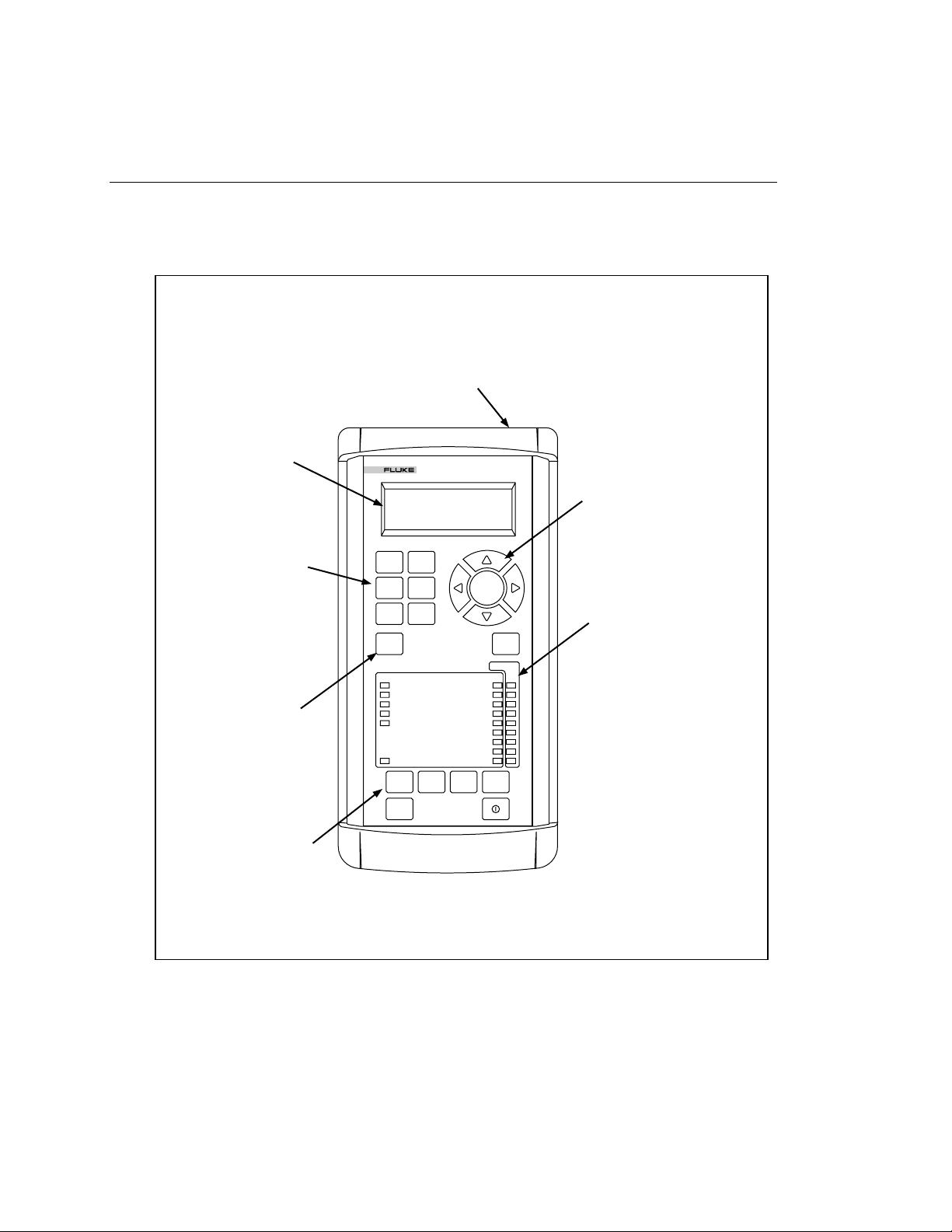
The OC3port Plus Handheld Tester: at a Glance
The OC3port Plus is an easy-to-use handheld tester. It is rugged yet lightweight, so
you can use it anywhere.
RS-232 port provides an interface
for connecting to a printer, remote
control, and downloading test results
For-line by 20-characters
backlit LCD displays test
results and setup
parameters
Six function keys provide
direct access to setup and
configuration options
START/STOP key to
easily control the running
of tests
SONET
BERT
ALARMS
START
STOP
STATUS
STATUS SECTION LOS
ATM CELL LOCK SECTION LOF
ALARMS SECTION OOF
PATTERN / ERROR INSERT LINE FERF
LOOPBACK
POWER
PRINT MEMORY CLEAR DELETE
ESC
OC3port
ATM
AUTO
OPTIONS
PLUS
PATH LOSS OF POINTER
ENTER
CURRENT
LINE AIS
PATH FERF
PATH AIS
PATH YELLOW
EDIT
HISTORY
Arrow keys navigate through
menu items. Up and Down
keys display options. Left
and Right keys choose
settings
Front panel LEDs provide
immediate indications of
OC3 Section, Line, and Path
errors and alarms
1-6
Print stored test results to a
printer or PC
za001f.eps
Figure 1-1. OC3port Plus at a Glance
Artisan Technology Group - Quality Instrumentation ... Guaranteed | (888) 88-SOURCE | www.artisantg.com
Page 20

Specifications
This section describes the physical and operational characteristics of the OC3port
Plus.
OC3 Physical
Bit rate: 155.52 Mbps ± 20 ppm
Receiver:
• Single-mode version:
• Multi-mode version:
• UTP-155 version: ATM Forum UTP-155-PMD compliant
Transmit Outputs:
• Single-mode version:
OC3port Plus Features and Capabilities
Maximum input power: -8 dBm
Minimum receive sensitivity: -28 dBm
Maximum input power: -14 dBm
Minimum receive sensitivity: -32.5 dBm
Introduction
1
Average output power: -12.5 dBm (typical)
Range: -15 dBm to -8 dBm
Center wavelength: 1260 to 1360 nm, spectral width: 7.7 nm
• Multi-mode version:
Average output power range: -19 dBm to -14 dBm
Center wavelength: 1270 to 1380 nm, spectral width: 130 nm
• UTP-155 version: ATM Forum UTP-155-PMD compliant
NRZ encoded
Transmit level: 0.90 - 1.10 Vpp
1-7
Artisan Technology Group - Quality Instrumentation ... Guaranteed | (888) 88-SOURCE | www.artisantg.com
Page 21

OC3port Plus
Users Manual
Physical
Power
Environmental
Size: Approximately 10 in (L) by 6.75 in (W) by 2 in (H)
Weight: 2.50 lbs.
Display: Back-light, 4-line by 20-character text
Connectors:
Single-mode version: FC/PC or SC Duplex
Multi-mode version: SC Duplex
UTP-155 version: RJ-45
AC operations: Operates from an external AC adapter/charger.
Battery type: Operates from internal rechargeable Ni-Cad battery.
Battery life: Minimum battery life is three hours of continuous use.
Recharge time: 12 hours.
Operating temperature: 0 °C to 50 °C
Storage temperature: -20 °C to +60 °C
Humidity: 5 % to 90 % non-condensing
Serial Communications Port
Port: EIA/RS-232
Connector: RJ-11 connector
Baud rates: 1200, 2400, 9600
Flow control: XON/XOFF or RTS/CTS
Standards Compliance
Applicable sections of ATM Forum UNI 3.1
Applicable sections of ANSI T1.105
Applicable sections of BellCore TR-NWT-000253
Applicable sections of ITU I.432, ITU I.610, and ITU I.510
1-8
Artisan Technology Group - Quality Instrumentation ... Guaranteed | (888) 88-SOURCE | www.artisantg.com
Page 22

Regulatory Compliance
Instrument complies with ETL product category 31
Instrument complies with FCC Part 15, Subpart B, Class A
OC3 Errors Detected
Section, Line, and Path Bit Interleave Parity errors; Line and Path Far-End-Block
errors.
OC3 Alarms Detected
Signal Loss, Loss of Frame, Line FERF, Line AIS, Path FERF, Path AIS, Path
YELLOW, Loss of Pointer alarms.
OC3 Alarms Generated
Signal Loss, Loss of Frame, Line FERF, Line AIS, Path FERF, Path AIS,
Path YELLOW alarms.
SDH-STM-1 Support
SDH option available which provides control and monitoring of S-bits.
Introduction
OC3port Plus Features and Capabilities
1
Pointer Features
Positive and negative pointer adjustment, programmable pointer value, viewable
received pointer value: current, minimum, and maximum.
ATM Layer
Cell mapping: ATM cells carried in the OC3 payload are byte-aligned.
Cell rate adaptation: Provided by the insertion of idle cells.
Cell delineation: Performed using the HEC mechanism as described in ITU I432.
HEC is generated and checked as described in ITU I.432.
1-9
Artisan Technology Group - Quality Instrumentation ... Guaranteed | (888) 88-SOURCE | www.artisantg.com
Page 23

OC3port Plus
Users Manual
Notices, Warnings, Operating Restrictions
This product complies with UL 1950 (2/26/93). This compliance has been certified
for both the United States and Canada by ETL Testing Laboratories and will carry
the ETL listing mark. This product meets the requirements of
FCC Part 15-Subpart A, electronics emission and susceptibility.
Service and adjustment of this unit is to be performed only by trained Fluke
service personnel. The following general safety precautions must be observed
during all phases of operation, service and repair of this instrument. Failure to
comply with these precautions or with specific warnings in this book violate safety
standards of design, manufacture, and intended use of this instrument. Fluke
Corporation assumes no liability for the customer’s failure to comply with these
requirements.
Potential Danger
• Explosion Hazard: Do not operate the system in the presence of flammable
gases.
• Hazardous Material: Should the LCD display become damaged, the liquid
crystal material can leak. Avoid all contact with this material, especially
swallowing. Use soap and water to thoroughly wash all skin and clothing
contaminated with the liquid crystal material.
1-10
• Electric Shock Hazard: Do not remove the system covers. To avoid electric
shock, use only the supplied power module.
• Laser: This product contains a Class 1 Laser Device. Do not look into the
connector labeled "output". Invisible laser energy is emitted from that
connector whenever the laser is on.
Warning
AC adapter/charger:
Only the Fluke-supplied AC adapter/charger may be used
with this equipment. The use of any other AC
adapter/charger is expressly forbidden and will void all
warranty rights.
Outlet:
The AC socket outlet shall be installed near the equipment
and shall be easily accessible. Failure to have this outlet
easily accessible may constitute a safety hazard.
Artisan Technology Group - Quality Instrumentation ... Guaranteed | (888) 88-SOURCE | www.artisantg.com
Page 24

Laser Operation
The single-mode version of the OC3port Plus contains a laser transmitting device.
As a safety precaution, this transmitter is off when the tester is powered on. For
the tester to function, you must turn on the laser setting. See "Starting the OC3port
Plus" in Chapter 3 for instructions on how to turn on the laser transmitter. The
laser turns on automatically if there is an input signal while you are running the
automatic diagnostic tests.
Checking Your Package
Take time to check your OC3port Plus package. The following items are included:
• 3'TSVX4PYW2IX[SVO%REP]^IV9WIVW1ERYEP
• %'EHETXIVGLEVKIV
• 3'TSVX4PYWRIX[SVOEREP]^IV
• 6.XS6.GEFPI
• 6.XS(&JIQEPIEHETXIV
• (&XS(&JIQEPIEHETXIV
• DB-9 to DB-25 male adapter
If your package does not contain an item from this list contact Fluke at one of the
telephone numbers listed under "Technical Support" below.
Introduction
Laser Operation
1
Technical Support
Fluke Corporation offers a variety of support options to help you get the most from
your OC3port Plus. If you require technical support, please have the following
information available:
• Your name and company.
• OC3port Plus model number and serial number.
• OC3port Plus software revision that appears when you power on the unit.
• Any error messages or flags that appear on the screen.
• Make, model numbers, and configurations of equipment under test.
• A printout of the setup parameters for the OC3port Plus.
For application or operation assistance or information about the OC3port Plus,
call:
USA and Canada: 1-888-993-5853
Europe: +31 402-678-200
Japan: +81-3-3434-0181
Singapore: +65-738-5655
Anywhere in the world: +1-425-356-5500
Or, visit Fluke’s web site at
www.fluke.com.
1-11
Artisan Technology Group - Quality Instrumentation ... Guaranteed | (888) 88-SOURCE | www.artisantg.com
Page 25

OC3port Plus
Users Manual
Service Center Repair
If the OC3port Plus requires service, pack it in the original shipping container and
send it, postage paid and insured, to the nearest Fluke Service Center. Include a
written description of the problem. Fluke assumes no responsibility for shipping
damage.
If the OC3port Plus is covered under warranty, it will be properly repaired or
replaced (at Fluke’s option) and returned to you, postage paid, at no charge. See
the registration card for warranty terms. If the warranty has lapsed, Fluke will
repair the unit for a fixed fee and return it to you postage paid. Contact the nearest
Service Center for information and repair prices.
For service information in the USA, call 1-888-99-FLUKE (1-888-993-5853).
Outside the USA, contact the nearest Service Center.
Visit Fluke’s web site at
www.fluke.com.
1-12
Artisan Technology Group - Quality Instrumentation ... Guaranteed | (888) 88-SOURCE | www.artisantg.com
Page 26

Chapter 2
Getting Started
Contents Page
Introduction...................................................................................................... 2-3
OC3port Plus Controls and Connections......................................................... 2-3
The Connector Panel................................................................................. 2-3
The Front Panel......................................................................................... 2-4
The LCD............................................................................................... 2-4
Direct Access Keys............................................................................... 2-5
Status Section........................................................................................ 2-7
System Control Keys............................................................................ 2-10
Getting Acquainted with the OC3port Plus Menus......................................... 2-12
Accessing a Menu..................................................................................... 2-13
Using the Directional Arrow Keys............................................................ 2-14
Scrolling through Menu Options .......................................................... 2-14
Changing the Setting for an Option...................................................... 2-15
Editing the Setting for an Option.......................................................... 2-16
Accessing OC3port Plus Submenus.......................................................... 2-17
Exiting OC3port Plus Submenus .............................................................. 2-18
Connecting the OC3port Plus.......................................................................... 2-18
Connecting the OC3port Plus to Network Devices................................... 2-19
Connecting to Remote Devices................................................................. 2-19
Connecting the OC3port Plus to a PC or Laptop.................................. 2-19
Connecting the OC3port Plus to a Modem........................................... 2-20
Connecting to a Printer.............................................................................. 2-20
Connecting to an External Power Supply ................................................. 2-21
Artisan Technology Group - Quality Instrumentation ... Guaranteed | (888) 88-SOURCE | www.artisantg.com
2-1
Page 27

OC3port Plus
Users Manual
2-2
Artisan Technology Group - Quality Instrumentation ... Guaranteed | (888) 88-SOURCE | www.artisantg.com
Page 28

Introduction
Chapter 2 first acquaints you with the physical layout of the OC3port Plus so that
you know where the various controls and connections are located and understand
the functions of the keys and general status indicators. Next, it describes the menu
interface and shows you how to access the menus and navigate through them.
Finally, chapter 2 describes how to connect the OC3port Plus to an external power
source and how to connect the tester to the network and to remote devices.
OC3port Plus Controls and Connections
The OC3port Plus has two main panels: a connector panel and a front panel with
status and control sections. Take a moment to become familiar with these two
panels so that you can work more efficiently.
The Connector Panel
Figure 2-1 is a representation of the OC3port Plus connector panel.
Getting Started
Introduction
2
RS232
IN
Single mode displayed
Figure 2-1. OC3port Plus Connector Panel
The connector panel, which is located on the top of the tester, has a 5V DC input
jack.
Use this jack to attach the AC adapter/charger supplied by Fluke Corporation.
OUT
5VDC
za002f.eps
2-3
Artisan Technology Group - Quality Instrumentation ... Guaranteed | (888) 88-SOURCE | www.artisantg.com
Page 29

OC3port Plus
Users Manual
The Front Panel
Warning
Do not disconnect the AC adapter/charger while the
OC3port Plus is powered on. Doing so can result in the
corruption of current or stored test results.
Only an AC adapter/charger supplied by Fluke can safely
be used with the OC3port Plus. Use of any other adapter
voids your warranty and can damage the tester.
Network connectors. The IN and OUT connector jacks are
attached to the OC3 network. Depending on the type of
interface, you will attach single-mode, multi-mode, or
twisted pair connections to these jacks.
EIA-232 serial port. This is a RJ-11 female jack that
accepts the Fluke-supplied serial conversion cable. Using
this cable, you can download to a PC or a printer and
upload the latest version of OC3port Plus software.
The front panel contains four main sections:
• LCD
2-4
• Direct access keys
• Status section
• System keys
Descriptions of these sections follow.
The LCD
The LCD is located at the top of the tester. It is a four-line by 20-character back-
light display that presents the OC3port Plus menus, test configurations, and results
of specific tests.
Artisan Technology Group - Quality Instrumentation ... Guaranteed | (888) 88-SOURCE | www.artisantg.com
Page 30

Direct Access Keys
The OC3port Plus has six direct access keys that provide immediate access to tests
and user setup options. These keys are located on the upper left side of the unit
directly across from the
Figure 2-2 is a representation of the LCD and the direct access keys.
ENTER key.
OC3port
Getting Started
OC3port Plus Controls and Connections
PLUS
2
SONET
BERT
ALARMS
START
STOP
ATM
AUTO
OPTIONS
ENTER
EDIT
Figure 2-2. OC3port Plus LCD and Direct Access Keys
za003f.eps
Artisan Technology Group - Quality Instrumentation ... Guaranteed | (888) 88-SOURCE | www.artisantg.com
2-5
Page 31

OC3port Plus
Users Manual
Direct Access Key Function
SONET Accesses OC3 and STS-3c setups and tests.
ATM Accesses ATM setups and tests.
BERT Accesses Bit Error Rate test parameters and tests.
AUTO Accesses automatic diagnostic tests and identifies virtual
ALARMS Displays, clears, and controls SONET alarms.
OPTIONS Stores user-defined opt8ions in internal memory.
START/STOP Starts and stops testing.
The Table 2-1 lists the six direct access keys other front panel keys and describes
their function.
Table 2-1. OC3port Plus Direct Access Keys and their Function
paths/channels with ATM activity.
In burst mode, pressing this key initiates a burst of ATM cells.
In transmit mode, pressing this key once pauses transmission;
pressing the key again causes transmission to resume.
EDIT Places the tester in Edit mode for changing the parameters for an
option.
ENTER Accepts user options and editing changes.
2-6
Artisan Technology Group - Quality Instrumentation ... Guaranteed | (888) 88-SOURCE | www.artisantg.com
Page 32

Status Section
The lower middle section of the front panel on the OC3port Plus contains 24 LEDs
that represent the operating and alarm status of the OC3port Plus and any attached
network.
Figure 2-3 is a representation of the status section.
STATUS
STATUS SECTION LOS
ATM CELL LOCK SECTION LOF
ALARMS SECTION OOF
PATTERN / ERROR INSERT LINE FERF
LOOPBACK
POWER
PATH LOSS OF POINTER
PATH FERF
PATH YELLOW
Getting Started
OC3port Plus Controls and Connections
HISTORY
CURRENT
LINE AIS
PATH AIS
2
Figure 2-3. OC3port Plus Status LEDs
The six general status LEDs appear on the left.
These LEDs provide laser transmitter status, ATM status, and power status
information.
za004f.eps
2-7
Artisan Technology Group - Quality Instrumentation ... Guaranteed | (888) 88-SOURCE | www.artisantg.com
Page 33

OC3port Plus
Users Manual
LED Name LED Condition Meaning
Table 2-2 lists the general status LEDs and their meanings.
Table 2-2. OC3port Plus General Status LEDs
STATUS Slow blinking
Constant Green
Indicates that the laser transmitter is set to
OFF. (for single-mode units only)
Indicates that the laser transmitter is set to
ON. (For single-mode units only).
ATM CELL LOCK On Indicates that ATM cell delineation has been
achieved.
ALARMS On Indicates that alarms are being transmitted
PATTERN / ERROR
INSERT
On Indicates that patterns or errors are being
transmitted.
LOOPBACK On Indicates that the unit is in line loopback or in
cell loopback mode.
POWER ON
Blinking
Indicates adequate AC or battery power.
Indicates that the battery is low on power.
The remaining 18 LEDs, found on the right side of the tester, indicate the status of
the connected SONET network.
The OC3port Plus can detect nine separate alarms.
The red LEDs indicate active or current alarms, while the yellow (History) LEDs
indicate that an alarm occurred at some time in the past but is no longer being
detected.
2-8
Artisan Technology Group - Quality Instrumentation ... Guaranteed | (888) 88-SOURCE | www.artisantg.com
Page 34

Getting Started
OC3port Plus Controls and Connections
Table 2-3 lists the alarms the OC3port Plus can detect and their meanings.
Table 2-3. SONET Alarms Detected by the OC3port Plus on the Status LEDs
SONET Status LED Description
2
SECTION LOS
(Loss of Signal)
SECTION LOF
(Loss of Frame)
SECTION OOF
(Out of Frame)
LINE FERF
(Far End Receive Failure)
LINE AIS
(Line Alarm Indication Signal)
Lights when an incoming optical OC3 signal cannot be
detected.
Declared when a Section OOF condition persists for
three milliseconds.
This three-millisecond timer does not reset until an in-
frame condition also persists for three milliseconds,
prohibiting oscillations and the declaration of an LOF
in the presence of intermittent OOF conditions.
Declared when four consecutive STS-3c frames
containing one or more framing pattern errors are
received.
A Section OOF alarm is removed when two sequential
frames with correct framing patterns are detected (an
in-frame condition).
Detects the presence of a Line FERF in the received
STS-3c stream.
Declared when a “110” pattern is detected in bits 6, 7
and 8 of the K2 framing byte for five consecutive
frames.
A LINE FERF alarm is removed when a pattern other
than “110” is detected for five consecutive frames.
Detects the presence of a Line FERF in the received
STS-3c stream.
Declared when a “111” pattern is detected in bits 6, 7
and 8 of the K2 framing byte for five consecutive
frames.
A Line AIS alarm is removed when a pattern other
than “111” is detected for five consecutive frames.
Artisan Technology Group - Quality Instrumentation ... Guaranteed | (888) 88-SOURCE | www.artisantg.com
2-9
Page 35

OC3port Plus
Users Manual
Table 2-3. SONET Alarms Detected by the OC3port Plus on the Status LEDs (cont.)
PATH FERF
(Far End Receive Failure)
SONET Status LED Description
Dedicated when the 4
Status Byte (G1) is set to “1001” for two consecutive
frames.
th
bit FEBE field within the Path
If any other pattern is present for two consecutive
frames, a Path FERF alarm is removed.
PATH AIS
(Alarm Indication Signal)
Declared when an all-ones pattern is detected in the
pointer bytes (H1 and H2) for three consecutive STS-3c
frames.
A Path AIS alarm is removed whenever a valid pointer is
detected in H1 and H2 for three consecutive frames.
PATH YELLOW Declared whenever bit 5 of the Path Status Byte (G1) is
set high (1) for five consecutive frames.
A path YELLOW alarm is removed when bit 5 returns
low (0) for five consecutive frames.
PATH LOSS OF POINTER Declared whenever a normal pointer (generally values
within the 0 to 782 range) is not found in eight
consecutive frames.
Path Loss of Pointer is removed when a valid pointer is
detected for three consecutive frames.
A received Path AIS indication does not result in a Path
Loss of pointer alarm.
Negative and Positive stuff indications do not trigger a
Path Loss of Pointer alarm.
System Control Keys
The system control keys are located at the bottom of the tester.
You use these keys to control the entire unit; for example, to turn the OC3port Plus
on and off (
ON/OFF key), to print configuration information and test results (PRINT
key), and to clear counters and delete alarms. (CLEAR key)
2-10
Artisan Technology Group - Quality Instrumentation ... Guaranteed | (888) 88-SOURCE | www.artisantg.com
Page 36

Getting Started
OC3port Plus Controls and Connections
Figure 2-4 is a representation of the system control keys, which are found on the
bottom part of the front panel.
PRINT MEMORY CLEAR DELETE
ESC
za005f.eps
Figure 2-4. The System Keys Control the Entire Unit.
2
Table 2-4 lists the system control keys and describes their usage.
Table 2-4. Description of the System Control Keys on the OC3port Plus
Key Name Description
ON/OFF Turns the unit on and off.
ESC A single press returns you to the introductory display (see
“Returning to the Introductory Display” in Chapter 3).
A double-press resets the OC3port Plus (see “Resetting the
OC3port Plus” in Chapter 3).
PRINT Prints test results and configuration information.
MEMORY Stores and retrieves test results.
CLEAR Resets the test result counters and deletes individual test
results.
DELETE Clears the alarm history LEDs and deletes stored results.
2-11
Artisan Technology Group - Quality Instrumentation ... Guaranteed | (888) 88-SOURCE | www.artisantg.com
Page 37

OC3port Plus
Users Manual
Getting Acquainted with the OC3port Plus Menus
The OC3port Plus is a menu driven system. Each time you power on the unit, a
series of self-tests and automatic ATM and SONET diagnostic tests is performed.
Note
The single-mode version of the OC3port Plus contains a laser
transmitting device. As a safety precaution, this transmitter is off
when the unit is powered on. You must turn the laser on each time
you turn on the unit. It remains on until you shut off the unit.
See "Turning on the Laser Transmitter" in this chapter for
instructions on how to turn on the laser transmitter. Note that the
laser comes on automatically if the OC3port Plus detects an input
signal while you are running the automatic diagnostic tests.
While the automatic tests are running, you see displays similar to this:
******************************
ANALYZING
SIGNAL 14
2-12
******************************
za006f.eps
When the tests are completed, you hear a "beep" and see the AUTOTEST SUMMARY
display, which looks like this:
AUTOTEST SUMMARY
- - - - - - - - - - - - - - - - - - - - - - - - -
ATM Detected: OK
Background: UNAS
za007f.eps
From this display, you can access any of the OC3port Plus menus. See "Accessing
a Menu", which follows in this chapter.
Artisan Technology Group - Quality Instrumentation ... Guaranteed | (888) 88-SOURCE | www.artisantg.com
Page 38

Accessing a Menu
You can access any OC3port Plus menu by simply pressing one of the six direct
access keys located under the LCD. For example, press the
OC3port Plus displays the following:
The display has four lines of information:
Getting Acquainted with the OC3port Plus Menus
OPTION SELECTIONS
- - - - - - - - - - - - - - - - - - - - - - -
Parameter Set 1
RS-232 Speed 96
Getting Started
2
OPTIONS key. The
za008f.eps
• Line 1 contains the menu title, which in this example is named
SELECTIONS
.
OPTIONS
• Line 2 is a dashed line. Depending on its location, this line indicates where
you are on a menu. If the line appears directly under the menu title, as it does
in this example, it is the
menu, it is the
end-of-menu bar.
top-of-menu bar. If it appears at the bottom of the
• Line 3 is the selection line. The arrow (È) to the left of the option means that
it can be selected or changed (when you are in edit mode). To the right of the
option is a greater-than symbol ("), which is followed by a . A greater-than
symbol can be followed by a number, a word, or a three-letter abbreviation,
which is the current value of the option. In this example, the current value for
the
Parameter Set option is .
Note
• When you press the
Left or Right Arrow key to change the setting of an option
that has a greater-than symbol (") after it, that new setting takes effect
immediately.
• Line 4 displays the next item on the menu, which in this case is
Speed
option
The OC3port Plus main menus contain a variety of items. These include:
• Options These present choices for you to make when programming
the RS-232
the OC3port Plus
• Actions These let you perform a test or setup function; for example,
Start BERT or Setup RX Filtrs.
• Test items
Artisan Technology Group - Quality Instrumentation ... Guaranteed | (888) 88-SOURCE | www.artisantg.com
These let you start or monitor test results
2-13
Page 39

OC3port Plus
Users Manual
Figure 2-5 is an illustration of the OC3port Plus menu system. All of the tester’s
functions are accessed through this menu system. On the first level is the
introductory display, which is the display you see when you first turn on or reset
the tester. On the second level are the six direct access keys. These keys control the
operation of the entire tester. When you press any one of these keys, you gain
direct access to the selected function and any of its related subfunctions.
FLUKE CORPORATION
OC3port+ 3.3
03-14-99 7:22:10 PM
SELECT MENU FUNCTION
Press ESC twice
to reset the OS3port+
SONET
SONET
SELECTIONS
Laser
Moniter STS-3c
Insert Errors
Setup STS-3c
Pointer Actions
Loopback STS-3c
ATM BERT AUTO ALARMS OPTIONS
ATM
SELECTIONS
Moniter ATM
Setup RX Filtrs
Setup XMIT Streams
Load XMIT Streams
ATM XMIT Mode
Cell Capture
Quality of Service
OAM Transmit
OAM Moniter
ATM Options
Load Temp Trfc Only
Load Temp Trfc & Hdr
BERT
SELECTIONS
Start BERT
Select BERT Pat
Setup Error Inj
Figure 2-5. OC3port Plus Menu System (Version 3.3)
Using the Directional Arrow Keys
You use the directional arrow keys to scroll through OC3port Plus menus and,
where applicable, to change parameters or edit values for options. There are four
arrow keys, each named for the direction in which they point: the
Down Arrow key, the Left Arrow key, and the Right Arrow key.
the
Scrolling through Menu Options
The Up and Down Arrow keys are used to scroll through the options listed on
OC3port Plus menus.
AUTO
SELECTIONS
IP Ping
AAL Type Detect
Auto Store
ATM Activity Scan
Start Auto Test
Review Auto Test
ALARM
SELECTIONS
Section LOS
Line AIS
Line FERF
Path AIS
Path FERF
Path YELLOW
LOS Action
View Alarm Log
OPTIONS
SELECTIONS
Parameter Set
RS-232 Speed
Scroll Method
Set Buzzer
Factory Defaults
User Info
General Info
Modem Init String
Date Time Editor
Beep Alarm/Err
Auto Test Featre
za009f.eps
Up Arrow key,
2-14
Artisan Technology Group - Quality Instrumentation ... Guaranteed | (888) 88-SOURCE | www.artisantg.com
Page 40

The scrolling behavior of the
programmable. The examples in this book assume that you are using
the default scrolling method, which is
this scrolling method, see "Changing the Default Scrolling Method"
in Chapter 3.
When you press the Down Arrow key, the menu selection that was previously on
the fourth line of the display moves up to the selection line. If you continue to
press this key, you eventually reach the end-of-menu bar, and the unit "beeps" if
you try to go past this point. To scroll in the opposite direction, press the Up
Arrow key.
Changing the Setting for an Option
The Left and Right Arrow keys are used to change the settings for options found on
OC3port Plus menus. The following example shows you how to use these keys to
change the setting for an option.
Getting Started
Getting Acquainted with the OC3port Plus Menus
Note
Up
and
Down Arrow
WIN
(for Windows). To change
keys is user-
2
1. Press the
change to the selection line. For example:
Up or Down Arrow key to move the option whose setting you want to
OPTION SELECTIONS
- - - - - - - - - - - - - - - - - - - - - - -
Parameter Set 1
RS-232 Speed 96
Note that the Parameter Set option is on the selection line as indicated by the
arrow to its left.
2. Press the
(in this example, the ) changes to one of the other available settings for this
option. Continue pressing the arrow key until the setting you want is displayed.
The change takes effect immediately. The value you display by pressing the
Left or Right Arrow key becomes the current setting for the option that is on the
selection line.
Left or Right Arrow key. Notice that the value of the current setting
za008f.eps
Artisan Technology Group - Quality Instrumentation ... Guaranteed | (888) 88-SOURCE | www.artisantg.com
2-15
Page 41

OC3port Plus
Users Manual
Editing the Setting for an Option
Some settings for an option require you to supply a value rather than select an item
from a menu. You do this by editing the current value of the setting. This example
shows you how to edit a setting.
1. Press the
ATM key. The ATM SELECTIONS menu is displayed:
ATM SELECTIONS:
- - - - - - - - - - - - - - - - - - - - - - -
Monitor ATM
Setup RX Filters
za010f.eps
2. Press the Down Arrow key until the Setup RX Filtrs option is on the selection
line, as in:
ATM SELECTIONS:
Monitor ATM
Setup RX Filtrs
Setup XMIT Streams
za011f.eps
3. Press ENTER. You see the RECEIVE FILTER 1 submenu:
2-16
RECEIVE FILTER: 1
or for Change
NAME:FILTER_1_
LOAD TX HDR TX1
za012f.eps
4. Press the Down Arrow key until the VCI setting is on the selection line (as
indicated by the blue directional arrows located on each side of the LCD).
Then, press the
The first character of the VCI field is flashing. This flashing character
indicates that you are now in Edit mode.
Artisan Technology Group - Quality Instrumentation ... Guaranteed | (888) 88-SOURCE | www.artisantg.com
EDIT key.
Page 42

Getting Started
Getting Acquainted with the OC3port Plus Menus
5. Press the Up or Down Arrow key until the value you want in the first position of
the VCI field is displayed. Then, press the
position.
Right Arrow key to move to the next
2
6. Continue pressing the
the
Right Arrow key to move to the next position in the field.
7. When you are finished making changes, do one of the following:
a. Press the
b. Press the
changes and restores the original value.
Accessing OC3port Plus Submenus
Many options on the OC3port Plus menus have an extended menu or submenu that
you have to access when you need to change their parameters. Some of the
OC3port Plus tests, for example, have many parameters, so to modify these, you
may have to access a submenu.
Typically, any option on a menu that appears by itself (that is, with no setting to its
right) has an additional menu (submenu) associated with it.
The following example shows you how to access an OC3port Plus submenu.
1. Press the
displayed. For example:
ENTER key. You exit Edit mode. The tester saves your changes.
EDIT key. You exit Edit mode. The tester does not save your
SONET direct access key. The SONET SELECTIONS main menu is
SONET SELECTIONS
- - - - - - - - - - - - - - - - - - - - - - -
Up or Down Arrow key to display the desired value and
Monitor STS-3c
Insert Errors
za013f.eps
2. Press the Down Arrow key until the Setup STS-3c option is on the selection line
as in the following:
SONET SELECTIONS
Insert Errors
Setup STS-3c
Pointer Actions
za014f.eps
Artisan Technology Group - Quality Instrumentation ... Guaranteed | (888) 88-SOURCE | www.artisantg.com
2-17
Page 43

OC3port Plus
Users Manual
3. Press ENTER. You are now accessing the STS-3c SETUP submenu:
STS-3c SETUP:
- - - - - - - - - - - - - - - - - - - - - - -
Path Auto YEL OFF
Line Auto FERF OFF
This submenu contains all of the STS-3c setup parameters. You navigate
through this and all other submenus by pressing the
move an option to the selection line and then pressing the
key to choose a value for the option.
Exiting OC3port Plus Submenus
To leave a submenu, simply press the ESC key to return to the introductory
display, or press any one of the direct access keys to begin a specific test or
perform a setup.
Connecting the OC3port Plus
Depending on the specific physical interface, the OC3port Plus is designed to be
connected to either intermediate-range, single-mode fiber systems, multi-mode
fiber optic systems, or unshielded twisted pair-155 systems. A single-mode
OC3port Plus uses fiber optic connectors located on the top of the tester.
The multi-mode version of the OC3port Plus is designed to be connected to multi-
mode fiber systems. This version uses the SC Duplex fiber-optic connectors
located on the top of the tester.
za015f.eps
Up or Down Arrow key to
Left or Right Arrow
2-18
The UTP-155 version of the OC3port Plus is designed to be connected to UTP-155
networks.
Artisan Technology Group - Quality Instrumentation ... Guaranteed | (888) 88-SOURCE | www.artisantg.com
Page 44

Connecting the OC3port Plus to Network Devices
You need the appropriate type of cable to connect the OC3port Plus to network
devices. You can contact Fluke to obtain a variety of fiber optic and UTP cables.
Warning
Do not move the fiber connectors from side to side as you
insert them into the receptacles. Doing so can cause the
alignment ferrule to break.
1. To receive signals from network devices, connect the fiber optic cable to the
OC3port Plus
2. To send signals on the line, connect the fiber optic cable to the OC3port Plus
OUT jack.
To create a loopback situation, complete both steps.
IN jack.
Connecting to Remote Devices
The OC3port Plus provides two methods of making remote (RS-232) connections:
direct and modem. The direct method allows you to connect the OC3port Plus to a
PC. You can then use the PC to control the OC3port Plus or to print test results. If
you prefer this type of connection, the PC must have the appropriate software to
control these functions. Contact Fluke Corporation for a programming book or
information about the Testview package.
Getting Started
Connecting the OC3port Plus
2
As an alternative, you can use the RS-232 line to connect the OC3port Plus to a
modem. After these connections are made, you must set the baud rate from the
OC3port Plus and change the communication settings from the receiving device.
Connecting the OC3port Plus to a PC or Laptop
To connect the OC3port Plus to a PC or laptop computer, do the following:
1. Connect the RS-232 line to the OC3port Plus.
2. Connect the other end to the computer serial port. If the computer has a DB-9
connector, use a DB-25-to-DB-9 converter.
3. Turn on the OC3port Plus.
4. Start the appropriate PC software.
2-19
Artisan Technology Group - Quality Instrumentation ... Guaranteed | (888) 88-SOURCE | www.artisantg.com
Page 45

OC3port Plus
Users Manual
Connecting the OC3port Plus to a Modem
When you use a modem, you must set the baud rate on the OC3port Plus and on
the receiving device. Follow these steps to set up the OC3port Plus for modem
communications:
1. Set up the OC3port Plus as described under "Connecting to the Network" in
this chapter.
2. Use the RS-232 line to connect the OC3port Plus to the modem.
3. Make the necessary hardware and software connections on the receiving end.
4. Turn on the OC3port Plus. Wait until the self-test ends (when the tester
"beeps").
5. Press the
OPTIONS key. The OPTION SELECTIONS menu is displayed:
OPTION SELECTIONS
- - - - - - - - - - - - - - - - - - - - - - -
Parameter Set 1
RS-232 Speed 96
6. Press the Down Arrow key until the RS-232 Speed option is on the selection
line. Then, press the
(96 = 9600 baud; 24 = 2400 baud; or 12 = 1200 baud).
7. When the port speed you want is displayed, press
The OC3port Plus is now connected to the modem. After the remote session
starts, the OC3port Plus simultaneously sends all test results.
Connecting to a Printer
To connect the OC3port Plus to a printer, do the following:
1. Connect the OC3port Plus to the serial port on the printer.
2. Power on the printer.
za008f.eps
Left or Right Arrow key to display the desired port speed
ENTER.
2-20
3. Power on the OC3port Plus.
Artisan Technology Group - Quality Instrumentation ... Guaranteed | (888) 88-SOURCE | www.artisantg.com
Page 46

Connecting to an External Power Supply
The power supply allows you to recharge the tester’s battery.
When the OC3port Plus is connected to an AC outlet, you can also use the power
supply as a continuous power source. In this way, you can test for long periods of
time without worrying about batteries.
To connect the OC3port Plus to an AC outlet, follow these steps:
1. Plug the power cable into an AC outlet.
2. Connect the power supply jack to the 5V DC outlet on the OC3port Plus.
Turn on the OC3port Plus and begin usage.
Getting Started
Connecting the OC3port Plus
2
Artisan Technology Group - Quality Instrumentation ... Guaranteed | (888) 88-SOURCE | www.artisantg.com
2-21
Page 47

OC3port Plus
Users Manual
2-22
Artisan Technology Group - Quality Instrumentation ... Guaranteed | (888) 88-SOURCE | www.artisantg.com
Page 48

Chapter 3
Setting Up and Operating
the OC3port Plus
Contents Page
Introduction..................................................................................................... 3-3
Programming the Overall Operation of the OC3port Plus .............................. 3-3
Changing the Default Scrolling Method................................................... 3-4
Turning on the Warning Buzzer ............................................................... 3-5
Setting the System Date and Time............................................................ 3-5
Setting the Communications Speed.......................................................... 3-6
Turning Off the Automatic Diagnostic Tests............................................ 3-7
Parameter Sets.......................................................................................... 3-8
Creating a Parameter Set...................................................................... 3-8
Naming a Parameter Set....................................................................... 3-10
Switching to a Different Parameter Set................................................ 3-11
Editing a Parameter Set........................................................................ 3-11
Performing Basic Operations.......................................................................... 3-12
Turning on the OC3port Plus.................................................................... 3-12
Turning on the Laser Transmitter............................................................. 3-14
Returning to the Introductory Display...................................................... 3-15
Resetting the OC3port Plus ...................................................................... 3-15
Restoring Factory Default Settings........................................................... 3-15
Clearing the Error Counters ...................................................................... 3-16
Responding to Low Battery Warnings...................................................... 3-16
Obtaining Information about Your OC3port Plus..................................... 3-17
Storing and Retrieving Test Results ......................................................... 3-17
Manually Storing Test Results ............................................................. 3-18
Automatically Storing Test Results in Memory................................... 3-19
Displaying Stored Test Results ............................................................ 3-22
Deleting Stored Test Results................................................................ 3-24
Deleting a Single Record...................................................................... 3-25
Deleting All Stored Records in a Test Group....................................... 3-25
Printing, Downloading, and Remote Control ........................................... 3-26
Artisan Technology Group - Quality Instrumentation ... Guaranteed | (888) 88-SOURCE | www.artisantg.com
3-1
Page 49

OC3port Plus
Users Manual
Connecting to the Serial Port................................................................ 3-26
Printing Reports and Configuration Information.................................. 3-29
Pausing a Print Job............................................................................... 3-30
Preventing a Report from Being Printed .............................................. 3-30
Controlling the OC3port Plus Remotely ................................................... 3-30
Running the Automatic Diagnostic Tests........................................................ 3-31
3-2
Artisan Technology Group - Quality Instrumentation ... Guaranteed | (888) 88-SOURCE | www.artisantg.com
Page 50

Setting Up and Operating the OC3port Plus
Introduction
Introduction
This chapter covers the basics of setting up and operating the OC3port Plus. The
first section shows you how to program the overall operation of the tester to
configure such elements as the scrolling method and the status of the key beeping
mechanism and how to set the date and time. It also shows you how to create
parameter sets so that you can store different but commonly used configurations in
separate groups and switch quickly between groups.
The second section covers basic OC3port Plus operations. You learn how to turn
on the unit and perform such fundamental tasks as clearing the display, resetting
the unit, storing and retrieving test results, and running diagnostic tests.
Programming the Overall Operation of the OC3port Plus
The OC3port Plus has a number of programmable setup options that enable you to
determine its overall operating characteristics. Any settings that you choose for
these options when you configure the OC3port Plus are stored in internal memory
so that even when you shut off the tester, you do not lose valuable configuration
information.
Following is a list of OC3port Plus setup options available for you to change:
3
• Scroll method
Determines the behavior of the arrow keys when you scroll through menus.
•
Buzzer operation
Enables/disables the sounding of a warning buzzer whenever you press an
invalid key.
•
Date/time setting
Sets the system date and time.
•
Communications speed
Sets the baud rate.
•
Automatic tests
Enable/disable the execution of a series of automatic diagnostic tests when you
power on the tester.
•
Parameter sets
Store two different configuration sets under the respective labels, Parameter
Set 1 and 2.
3-3
Artisan Technology Group - Quality Instrumentation ... Guaranteed | (888) 88-SOURCE | www.artisantg.com
Page 51

OC3port Plus
Users Manual
These setup options are found on the OPTION SELECTIONS menu. To display this
menu, press the
OPTIONS key. You see this display:
OPTION SELECTIONS
- - - - - - - - - - - - - - - - - - - - - - -
Parameter Set 1
RS-232 Speed 96
The following sections show you how to change these setup options so that you
can configure the tester to suit your personal style and work preferences:
Changing the Default Scrolling Method
You can change the way the arrow keys operate when you scroll through OC3port
Plus menus. There are two scrolling methods available:
• WIN In WIN mode, the arrow keys move the display window up or
down over the menus.
za008f.eps
• ARW In ARW mode, the arrow keys pull the menu up or down through
the display window.
The default scrolling method is
WIN. If you want to change to ARW mode for
scrolling, follow these steps: (for Windows) mode
1. From the
Scroll Method option to the selection line.
2. Press the
3. The change takes effect immediately.
Scroll Method option.
OPTION SELECTIONS menu, press the Down Arrow key to move the
Left or Right Arrow key to display the ARW setting.
ARW is now the current setting for the
3-4
Artisan Technology Group - Quality Instrumentation ... Guaranteed | (888) 88-SOURCE | www.artisantg.com
Page 52

Programming the Overall Operation of the OC3port Plus
Turning on the Warning Buzzer
The OC3port Plus has a warning buzzer that causes the unit to issue a "beep" when
you try to go beyond the top-of-menu or end-of-menu bar, or when you press the
MEMORY key to store information in the tester’s memory. This buzzer is controlled
by the
Set Buzzer option, which can be set to ON or OFF (the default).
To turn on the warning buzzer, do the following:
Setting Up and Operating the OC3port Plus
3
1. From the
OPTION SELECTIONS menu. Then, press the Down Arrow key to
move the Set Buzzer option to the selection line.
2. Press the
Left or Right Arrow key to change the setting for this option to ON.
The change takes effect immediately. The warning buzzer is now activated.
Setting the System Date and Time
The DateTime Editor is used to set the internal clock on the OC3port Plus. With
this editor, you can set the date in
hour : minute : time-of-day format. The tester uses the date and time you supply to
time-stamp stored test results and alarm information.
To set the date and time, follow these steps:
1. From the
DateTime Editor option to the selection line.
2. Press
OPTION SELECTIONS menu, press the Down Arrow key to move the
ENTER. The SET DATE and TIME submenu displays. For example:
SET DATE and TIME
- - - - - - - - - - - - - - - - - - - - - - MONTH JUN
DATE:07
month : day : year format and the time in
za016f.eps
3. Press the EDIT key to enter Edit mode. The current setting for MONTH flashes.
Press the
ENTER to save your selection.
Artisan Technology Group - Quality Instrumentation ... Guaranteed | (888) 88-SOURCE | www.artisantg.com
Up or Down Arrow key to display the desired month. Then, press
3-5
Page 53

OC3port Plus
Users Manual
4. Press the Down Arrow key to move DATE to the selection line. Then, press the
EDIT key. The number in the first position of the DATE field flashes.
Press the
Right Arrow key to move to the next position and enter the desired value there.
Finally, press
5. Press the
Up or Down Arrow key to display the desired number. Then, press the
ENTER to save your selection.
Down Arrow key to move YEAR to the selection line. Press the EDIT
key to enter Edit mode and make the necessary changes. Make sure you press
ENTER when you are done to save the change.
6. Press the
Down Arrow key to move TIME to the selection line. Press the EDIT
key to enter Edit mode and set the time. When you finish, press ENTER to save
your selection.
7. The tester is now configured with your date and time selections.
Setting the Communications Speed
To set the communications speed on the OC3port Plus, complete these steps:
1. From the
RS-232 Speed option to the selection line:
OPTION SELECTIONS menu, press the Down Arrow key to move the
OPTION SELECTIONS
Parameter Set 1
RS-232 Speed 96
Scroll Method WIN
za017f.eps
3-6
This option has these three settings:
• 96 9600 baud
• 24 2400 baud
• 12 1200 baud
2. Press the
Left or Right Arrow key to select the correct communications speed.
The change takes effect immediately. The OC3port Plus is configured with the
baud rate you selected.
Artisan Technology Group - Quality Instrumentation ... Guaranteed | (888) 88-SOURCE | www.artisantg.com
Page 54

Setting Up and Operating the OC3port Plus
Programming the Overall Operation of the OC3port Plus
Turning Off the Automatic Diagnostic Tests
When you first power on the OC3port Plus, it automatically conducts a series of
self-tests and diagnostic tests that assess the basic health of any OC3 signal
provided to its input connector. If no signal is present or if theOC3port Plus is not
yet connected to a network, the tester waits until a signal is detected.
After a signal is detected, the OC3port Plus begins a 25-second analysis of the
signal and its format. Then, the OC3port Plus displays a set of summary statistics
for both ATM and SONET. For information on the results provided by these tests,
see "Running the Automatic Diagnostic Tests" later in this chapter.
The automatic tests are conducted and results are displayed every time you power
on the OC3port Plus unless you prevent the tester from running them. The
instructions in this section show you how to do this.
Note
You can run the automatic tests under your own control. For
information on how to do this, see "Running the Automatic
Diagnostic Tests" later in this chapter.
If you want to prevent the OC3port Plus from running the diagnostic tests every
time you turn on the tester, do the following:
3
1. From the
AutoTest Featre option is on the selection line:
OPTION SELECTIONS menu, press the Down Arrow key until the
OPTION SELECTIONS
Beep Alarm/Err OFF
Auto Test Featre ON
- - - - - - - - - - - - - - - - - - - - - - -
za018f.eps
2. Press the Left or Right Arrow key to change the setting for this option to OFF.
The change takes effect immediately. The OC3port Plus does not perform the
automatic tests when you power on the unit.
Artisan Technology Group - Quality Instrumentation ... Guaranteed | (888) 88-SOURCE | www.artisantg.com
3-7
Page 55

OC3port Plus
Users Manual
Parameter Sets
The OC3port Plus can store in memory up to two distinct groups of user-defined
configurations under the respective labels Parameter Set 1and 2. Each group can
contain any of the programmable options available on the OC3port Plus. These
include any setups you create, the parameters and settings for tests, transmission
modes, ATM states, and BERT test patterns, to name a few.
Parameter sets are useful when you need to retain test setups and configurations
that you use frequently. For example, you can create one parameter set for BERT
testing and the other for ATM testing. Parameter sets are also useful when more
than one person uses the unit. Each user can store his or her own user definitions
for tests and setups in a separate parameter set.
You can use only one parameter set at any given time, but you can easily switch to
the other set and begin using its setups.
This section shows you how to do the following:
• Create a parameter set
• Name a parameter set
• Switch between parameter sets
• Edit a parameter set.
Creating a Parameter Set
When you turn on the OC3port Plus, it uses the parameter set that
was in use when the unit was last turned off. If this is the first time
that you are using the tester, the parameter set that is active when
you turn on the unit is Parameter Set 1.
To find out what parameter set you are currently in, press the
OPTIONS
through the list until you see the
the right of this option indicates which parameter set you are
currently in.
3-8
key to display the
Note
OPTION SELECTIONS
Parameter Set
option. The number to
menu. Scroll
Artisan Technology Group - Quality Instrumentation ... Guaranteed | (888) 88-SOURCE | www.artisantg.com
Page 56

Setting Up and Operating the OC3port Plus
Programming the Overall Operation of the OC3port Plus
Caution
Be careful when you restore the factory defaults because
any settings and configurations you previously stored in
Parameter Sets will be replaced by the factory default
values.
To create a parameter set, do the following:
3
1. Press the
OPTIONS key. The OPTION SELECTIONS menu is displayed:
OPTION SELECTIONS
- - - - - - - - - - - - - - - - - - - - - - -
Parameter Set 1
RS-232 Speed 96
za008f.eps
2. Make sure that the Parameter Set option is on the selection line. Then, press
the
Left or Right Arrow key to select the parameter set you want to create. For
example:
OPTION SELECTIONS
- - - - - - - - - - - - - - - - - - - - - - -
Parameter Set 2
RS-232 Speed 96
za019f.eps
In this example, Parameter Set 2 is selected.
3. Press the
you selected. In this example,
To make sure that the parameter set you selected is the active one,
press the
currently active is displayed to the right of the
In this example, the setting for the Parameter Set option is 2, which indicates
that Parameter Set 2 is the active parameter set.
Artisan Technology Group - Quality Instrumentation ... Guaranteed | (888) 88-SOURCE | www.artisantg.com
ENTER key. The tester resets itself and activates the parameter set
Parameter Set 2 is now activated.
Note
OPTIONS
key again. The number of parameter set that is
Parameter Set
option.
3-9
Page 57

OC3port Plus
Users Manual
4. You can now create the parameter set you selected. Any setups or
configurations that you create are automatically stored within this parameter
set as you make them.
Naming a Parameter Set
To distinguish one parameter set from another, you can give each a unique,
identifying name. For example, if one of your parameter sets contains ATM setups
and tests, you can give it the name "ATM Tests". Or, if you share the OC3port
Plus with another person and each of you has created a parameter set, you can each
identify your parameter set with your own name.
Follow these steps to create a name for your parameter sets.
1. Press the
2. Make sure that the
OPTIONS key. The OPTION SELECTIONS menu is displayed.
Parameter Set option is on the selection line. Do one of the
following:
a. If you want to name the active parameter set, go to Step 3.
Note
The active parameter set is the one represented by the number to the
right of the
b. If want to name one the other parameter set, press the
Parameter Set
option.
Left or Right Arrow
key to display the desired set. Then, press ENTER. The OC3port Plus
reboots and activates the parameter set you selected. Go to Step 3.
3. Press the
Then, press
Down Arrow key to move the User Info option to the selection line.
ENTER. You see this display:
USER INFO
INFO: UNASSIGNED_ _
za020f.eps
3-10
Artisan Technology Group - Quality Instrumentation ... Guaranteed | (888) 88-SOURCE | www.artisantg.com
Page 58

Setting Up and Operating the OC3port Plus
Programming the Overall Operation of the OC3port Plus
You are in Edit mode as indicated by the flashing "U" in the first position of
the
INFO field. The name UNASSIGNED is the default name assigned to each
parameter set.
The name you choose can be one to ten characters long.
3
4. Press the
position of the
5. Then, press the
Up or Down key to display the desired letter or number in the first
INFO field.
Right Arrow key to move to the next position.
6. Continue pressing the arrow keys in this manner until the name you want is
displayed.
7. When you finish, press
ENTER to save the newly created name.
Complete this procedure for each parameter set that you want to name.
Switching to a Different Parameter Set
To switch to the other parameter set, follow these steps:
1. Press the
2. Make sure that the
3. Then, press the
OPTIONS key. The OPTION SELECTIONS menu is displayed.
Parameter Set option is on the selection line.
Left or Right Arrow key to display the number of the parameter
set that you want to switch to.
4. Press
ENTER.
The OC3port Plus immediately reboots and switches to the parameter set that
you selected.
Editing a Parameter Set
When you change the setting for an option or re-configure a setup, those changes
are automatically stored in the parameter set that is currently active.
Therefore, when you want to edit a parameter set, first activate the parameter set
that you want to edit. (See "Creating a Parameter Set" if you need to know how to
activate a parameter set.)
Then, make the desired changes, which the OC3port Plus automatically stores in
the parameter set you are working in.
Artisan Technology Group - Quality Instrumentation ... Guaranteed | (888) 88-SOURCE | www.artisantg.com
3-11
Page 59

OC3port Plus
Users Manual
Performing Basic Operations
You need to know some fundamental things about how to operate the OC3port
Plus before you can start configuring the unit to perform tests or acquiring test
results.
In this section, you learn how to turn on the unit then how to do essential tasks that
you will need to operate the OC3port Plus.
Turning on the OC3port Plus
The OC3port Plus has an ON/OFF switch built into the membrane keypad.
This switch is located in the lower right corner as shown in Figure 3-1.
PRINT MEMORY CLEAR DELETE
ESC
Figure 3-1. OC3port Plus ON/OFF switch
za005f.eps
3-12
Artisan Technology Group - Quality Instrumentation ... Guaranteed | (888) 88-SOURCE | www.artisantg.com
Page 60

Setting Up and Operating the OC3port Plus
To turn on the OC3port Plus, do the following:
Performing Basic Operations
3
1. Press the
The OC3port Plus performs a series of automatic self-tests and other signal
verification tests. When these tests are completed, all of the status LEDs on its
front panel light. The unit "beeps" and you see a display similar to the
following:
ON/OFF switch.
AUTOTEST SUMMARY
- - - - - - - - - - - - - - - - - - - - - - - - -
ATM Detected: OK
Background: UNAS
za007ff.eps
Note
If you want to prevent the OC3port Plus from performing these
automatic tests, see "Turning Off the Automatic Diagnostic Tests" in
this chapter. If you want information about this test and the types of
results it provides, see "Running the Automatic Diagnostic Tests"
also in this chapter.
2. You can now press any one of the direct access keys to select tests or set up
configurations.
Note
If you are using a single-mode OC3port Plus, the first line of the
display flashes a *LASER OFF* message if you power on the unit
with no input signal present. If you want to perform tests that use the
SONET transmitter, you must turn the laser on. For information on
how to do this, see "Turning on the Laser Transmitter" in this
chapter.
3. When you finish using the unit, press the
The OC3port Plus shuts off and saves all of your setup information in its
internal memory.
ON/OFF switch.
3-13
Artisan Technology Group - Quality Instrumentation ... Guaranteed | (888) 88-SOURCE | www.artisantg.com
Page 61

OC3port Plus
Users Manual
Turning on the Laser Transmitter
This procedure applies only if you are using a single-mode OC3port
Plus.
When the laser transmitter is off, the top line of all OC3port Plus
flashes the
*LASER OFF*
After you turn on the transmitter, the message disappears and the
STATUS LED
When you first turn on the single-mode version of the OC3port Plus, the laser
emits a steady green light.
transmitter may be set to
ON.
to
To turn the laser on, follow these steps.
Notes
message, and the
OFF. If you want to transmit, you must set the transmitter
STATUS LED
blinks.
1. Press the
SONET key. The SONET SELECTIONS menu is displayed. For
example:
SONET SELECTIONS
- - - - - - - - - - - - - - - - - - - - - - -
Laser OFF
Monitor STS-3c
2. The Laser option is on the selection line. In this example, notice that the
setting is
3. Press the
The change takes effect immediately. The *LASER OFF* message
disappears, indicating that the transmitter is now on.
OFF.
Right Arrow key to change the setting to ON.
za022f.eps
3-14
Artisan Technology Group - Quality Instrumentation ... Guaranteed | (888) 88-SOURCE | www.artisantg.com
Page 62

Returning to the Introductory Display
Whenever you are finished with a particular function (for example, monitoring test
results or performing setups), you can return to the introductory display from any
menu or submenu by pressing the
introductory display:
ESC key. The unit returns you to this
Setting Up and Operating the OC3port Plus
Performing Basic Operations
3
FLUKE CORPORATION
OC3port+ 3.3
03-14-99 7:22:10 PM
SELECT MENU FUNCTION
Resetting the OC3port Plus
You reset the OC3port Plus by pressing the ESC key twice within one second.
When you reset the tester, it performs a self-test and leaves you at the introductory
display. This function is useful when you want to put the OC3port Plus in a known
state.
When you reset the OC3port Plus, it does not restore the default settings. For
information on restoring these settings, see "Restoring Factory Default Settings" in
this chapter.
Restoring Factory Default Settings
You can reset the OC3port Plus so that the settings for menu options are the same
as they were when the unit was shipped from the factory. To restore the factory
default settings, follow these steps:
Be careful when you restore the factory defaults because
any settings and configurations you previously stored in
Parameter Sets 1 through 4 are replaced by the factory
default values.
za023f.eps
Caution
Artisan Technology Group - Quality Instrumentation ... Guaranteed | (888) 88-SOURCE | www.artisantg.com
3-15
Page 63

OC3port Plus
Users Manual
1. Press the OPTIONS key. The OPTION SELECTION menu is displayed:
2. Press the Down Arrow key until the Factory Defaults option is on the selection
line:
3. Press ENTER. The unit issues a short "beep" and resets to the factory defaults.
You return to the introductory display.
Clearing the Error Counters
If there are errors on a signal, they are presented on the LCD. As certain errors are
detected, the counters on the display continuously increase. To clear the display of
any errors and reset the error counter to zero, press the
viewing the errors on the LCD.
OPTION SELECTIONS
- - - - - - - - - - - - - - - - - - - - - - -
Parameter Set 2
RS-232 Speed 96
CLEAR key while you are
za019f.eps
Responding to Low Battery Warnings
The OC3port Plus uses NiCad internal batteries. These batteries last for about one
year. When the battery charge is low, the OC3port Plus issues periodic "beeps"
and then displays a LOW BATTERY warning on the LCD. When this situation
occurs, the unit has approximately five minutes of battery power remaining. We
suggest that you use the remaining time to immediately store any current test
results and then recharge the unit.
If the battery does not charge, contact Fluke Customer Service for
replacement batteries.
You can connect the tester to the supplied AC adapter/charger and charge it
without shutting it off. On a full battery charge, which takes between 12 to 14
hours, the OC3port Plus will run for approximately three hours.
The AC adapter/charger should never be disconnected
while the OC3port Plus is powered on. This can cause
corruption of current or stored test results.
3-16
Note
Caution
Artisan Technology Group - Quality Instrumentation ... Guaranteed | (888) 88-SOURCE | www.artisantg.com
Page 64

Setting Up and Operating the OC3port Plus
Obtaining Information about Your OC3port Plus
If you ever require technical assistance you will need to provide certain
information about your OC3port Plus, such as the software revision number, serial
number, and model type. This procedure shows you how to obtain this and other
pertinent information about your OC3port Plus.
1. Press the OPTIONS key. The OPTIONS SELECTIONS menu is displayed.
Performing Basic Operations
3
2. Press the
line. Then, press
Down Arrow key to move the General Info option to the selection
ENTER. You see a display similar to the following:
GENERAL INFO
- - - - - - - - - - - - - - - - - - - - - - - -
SOFTWRE REV: 3.3
MODEL TYPE :OC3-P1
This display contains the following information:
• 7SJX[EVIVIZMWMSRRYQFIV
• 1SHIPX]TI
• 0MWXSJMRWXEPPIHSTXMSRW
• 8VERWGIMZIVX]TIWMRKPIQSHIQYPXMQSHISV984
• )PIGXVSRMGWIVMEPRYQFIV
• Remote (indicates whether your unit is enabled or disabled for remote
control).
Storing and Retrieving Test Results
You can store results from the many OC3port Plus tests in memory for later use
and review. These results remain in memory even after you shut off the unit. This
section shows you how to do the following:
za025f.eps
• 7XSVIXIWXVIWYPXWQERYEPP]ERHEYXSQEXMGEPP]
• (MWTPE]WXSVIHXIWXVIWYPXW
• (IPIXIWXSVIHXIWXVIWYPXW
• Print stored test results.
Using the Auto Store option, you can program the OC3port Plus to automatically
store test results in memory as they are acquired. The
used to automatically send test results periodically to the printer. This section also
shows you how to set up the OC3port Plus for automatic test storage.
Artisan Technology Group - Quality Instrumentation ... Guaranteed | (888) 88-SOURCE | www.artisantg.com
Auto Store option can also be
3-17
Page 65

OC3port Plus
Users Manual
Manually Storing Test Results
To store test results, press the MEMORY key while viewing the results on the LCD.
After you press the
message indicates that the result you are viewing has been stored in the tester’s
memory. Any results you store are retained even after you turn off the OC3port
Plus.
You can store LED status records and results from any of the following tests:
• &)68
• %81'IPPPSWW
• 732)8
• Automatic tests.
Depending on the type of test record, the OC3port Plus has a limitation on the
number of records that it can store in memory. In addition, the tester’s storage is
circular so that when the limitation for a particular test is reached, the record at the
bottom of the stack is deleted as a new record is added to the top.
Table 3-1 provides a list of storage limitations for each group of test records that
you can store:
MEMORY key, you see this message: RECORD SAVED. This
Table 3-1. Storage Limits for Test Records
3-18
Test Records Storage Limit
BERT 100
LED Status 100
ATM cell loss 128
Alarm 128
Counters 32
Automatic diagnostic tests 10
Artisan Technology Group - Quality Instrumentation ... Guaranteed | (888) 88-SOURCE | www.artisantg.com
Page 66

Setting Up and Operating the OC3port Plus
Automatically Storing Test Results in Memory
In this procedure, you will set up the OC3port Plus to automatically store test
results. This entails selecting which test results to store and setting the timing
criteria which determines how frequently those results are collected and stored.
To set up the OC3port Plus to automatically collect and store test results:
1. Press the AUTO key to display the AUTO SELECTIONS menu.
Performing Basic Operations
3
2. Press the
press
option
Down Arrow key to move the Auto Store to the selection line. Then,
ENTER. The AUTO STORE submenu is displayed, as in the following:
AUTO STORE:
- - - - - - - - - - - - - - - - - - - - - - - -
Auto Store OFF
Select Period
za026f.eps
3. Make sure that the Auto Store option is on the selection line. This option has
two settings:
•
OFF (the default)
Turns off the automatic test storage feature.
•
ON
Turns on the automatic test storage feature.
4. Press the Left or Right Arrow key to change the Auto Store setting to ON.
Artisan Technology Group - Quality Instrumentation ... Guaranteed | (888) 88-SOURCE | www.artisantg.com
3-19
Page 67

OC3port Plus
Users Manual
5. Press the Down Arrow key to move the Select Period option to the selection
line. Then, press
ENTER. The display shows:
SET PERIOD
PERIOD: 00D 00H 01M
On this display, you can set a value that determines how frequently the
OC3port Plus stores test results. The format is
of days,
For example, if you wanted to store test results every 7 days, 5 hours, and 10
minutes, your display would look like this:
H is the number of hours, and M is the number of minutes.
D / H / M, where D is the number
SET PERIOD
PERIOD: 07D 05H 10M
za027f.eps
3-20
za028f.eps
6. You are in Edit mode. To set a time period for collection and storage, press the
arrow keys to supply the desired value. When, you finish, press
ENTER to save
the change.
7. Press the AUTO key again. You return to the AUTO SELECTIONS menu.
8. Make sure that the Auto Store option is on the selection line. Then, press
ENTER to re-display the AUTO STORE submenu.
Artisan Technology Group - Quality Instrumentation ... Guaranteed | (888) 88-SOURCE | www.artisantg.com
Page 68

Setting Up and Operating the OC3port Plus
Performing Basic Operations
9. Press the Down Arrow key to move the Destination option to the selection line,
as in the following:
AUTO STORE:
Select Period
Destination PRT
Bert OFF
za029f.eps
This option determines where the OC3port Plus sends the test results. This
option has three settings:
• PRT Sends results to an attached printer.
• MEM Stores results in memory.
• BTH Sends results to an attached printer and stores them in memory.
10. Press the Left or Right Arrow key to choose the desired destination.
3
11. Press the Down Arrow key to move each of the following options to the
selection line:
•
Bert
• Cell Loss
• Counters
• Alarm Status
These options determine which test records the OC3port Plus stores
automatically.
Each option has two settings,
When set to
and stored.
When set to
ON, test records for the selected option are automatically collected
OFF, no records are automatically stored.
ON and OFF.
Artisan Technology Group - Quality Instrumentation ... Guaranteed | (888) 88-SOURCE | www.artisantg.com
3-21
Page 69

OC3port Plus
Users Manual
12. Press the Left or Right Arrow key to choose the desired setting for each test
record that you want to automatically collect and store records for.
In the following example, the OC3port Plus is set up to automatically collect
and store BERT test records.
AUTO STORE:
Setup is completed.
The OC3port Plus is now configured to automatically collect and store test
records.
Displaying Stored Test Results
To display test results stored in memory, do the following:
Destination PRT
Bert ON
Cell Loss OFF
za030f.eps
1. Press the
AUTO key. The AUTO SELECTIONS menu is displayed.
2. Make sure that the
3. Then, press
The
AUTO STORE submenu is displayed:
ENTER.
AUTO STORE:
- - - - - - - - - - - - - - - - - - - - - - - -
Auto Store OFF
Select Period
Auto Store option is on the selection line.
za026f.eps
3-22
Artisan Technology Group - Quality Instrumentation ... Guaranteed | (888) 88-SOURCE | www.artisantg.com
Page 70

Setting Up and Operating the OC3port Plus
Performing Basic Operations
4. Press the Down Arrow key until the Review Records is on the selection line.
Then, press
ENTER. The REVIEW RECORDS submenu is displayed: option
REVIEW RECORDS:
- - - - - - - - - - - - - - - - - - - - - - - -
Bert
Cell Loss
za031f.eps
This menu has the following choices, representing the four types of test
records that the OC3port Plus can store:
• &IVX
• 'IPPPSWW
• 'SYRXIVW
• Alarm Status
5. Make sure that the name of the group containing the test results you want to
review is on the selection line. Then, press
the test group you selected is displayed. If no records are stored, you see this
message: NO RECORDS COLLECTED. Following is a sample OC3port Plus
test record:
ENTER. The first record stored in
3
BERT RECORD 5/11
6797 OOF
03-12-99 11:44:19AM
za032f.eps
Note that, when saved, each result is categorized by the type of test (in this
example, BERT). A counter to the right of the test name indicates which
record you are viewing (in this example, record 5 out of a total of 11). Line 2
of the display indicates the number and type of error recorded (in this
example, 6797 OOF). At the bottom of the display, the date and time that the
record was stored is given (in this example, the record was stored on March
12, 1996 at 11:44:19 a.m.).
3-23
Artisan Technology Group - Quality Instrumentation ... Guaranteed | (888) 88-SOURCE | www.artisantg.com
Page 71

OC3port Plus
Users Manual
The Left and Right Arrow keys can be used to cycle through the various display
formats available for the particular record you are reviewing. For example, by
pressing these keys, you can view these two additional displays for BERT
records stored in memory:
BERT RECORD 5/11
1.00E-03 BER
3.016E+05 ERRORS
3.016E+08 BITS
za033f.eps
BERT RECORD 5/11
5 E/S
1 ESEC
0 THSEC
za034f.eps
Press the Up or Down Arrow key to view additional records that you have
stored. In this example, pressing the
the ten remaining BERT records.
Deleting Stored Test Results
You can delete stored test records individually or you can delete all records in a
particular group from memory.
3-24
Up or Down Arrow key allows you to see
Artisan Technology Group - Quality Instrumentation ... Guaranteed | (888) 88-SOURCE | www.artisantg.com
Page 72

Deleting a Single Record
To delete a single test record, follow these steps:
Be careful when you delete a stored test record. Deleting
a stored test record cannot be undone.
Setting Up and Operating the OC3port Plus
Performing Basic Operations
Caution
3
1. Press the
2. Make sure that the
ENTER. The AUTO STORE submenu is displayed.
AUTO key to display the AUTO SELECTIONS menu.
Auto Store option is on the selection line. Then, press
3. Press the Down Arrow key to move the
Then, press
ENTER. The REVIEW RECORDS submenu is displayed: option
REVIEW RECORDS:
- - - - - - - - - - - - - - - - - - - - - - - -
Bert
Cell Loss
4. Move the name of the group containing the test record you want to delete to
the selection line. Then, press
selected is displayed.
5. Press the
Up or Down Arrow key to display the particular test record you want
to delete. Then, press the
is deleted from the tester’s memory.
Deleting All Stored Records in a Test Group
To delete all test records in a group from storage, do the following:
ENTER. The first test record in the group you
CLEAR key. The individual test record you selected
Review Records to the selection line.
za031f.eps
Warning
Be careful when you delete a stored test record. Deleting
a stored test record cannot be undone.
1. Press the
2. Make sure the
The
3. Press the
line. Then, press
Artisan Technology Group - Quality Instrumentation ... Guaranteed | (888) 88-SOURCE | www.artisantg.com
AUTO key to display the AUTO SELECTIONS menu.
Auto Store option is on the selection line. Then, press ENTER.
AUTO STORE submenu is displayed.
Down Arrow key to move the Delete Records option to the selection
ENTER. The DELETE RECORDS submenu is displayed:
3-25
Page 73

OC3port Plus
Users Manual
DELETE RECORDS:
- - - - - - - - - - - - - - - - - - - - - - - -
Bert
Cell Loss
4. Make sure that the name of the group whose records you want to delete is on
the selection line. Then, press
All of the tests in the group you selected are deleted from the tester’s memory.
Printing, Downloading, and Remote Control
On its connector panel, the OC3port Plus has an EIA-232 serial port, which is
designed into an RJ-11 (telephone) jack. With this port, you can:
• Connect the OC3port Plus to a serial printer.
• Connect the OC3port Plus to a PC that is running any standard
communications terminal program (such as Procomm or Crosstalk) and
capture test results and configuration information.
za035f.eps
ENTER.
• Control the operation of the OC3port Plus remotely.
The information in this section shows you how to set up your OC3port Plus for
printing and remote control operation.
Connecting to the Serial Port
To connect your OC3port Plus to a computer, printer, or modem you need the
following equipment, which is supplied with the OC3port Plus:
• RJ-11 to RJ-11 cable
• RJ-11 to DB-25s female adapter for connection to a computer
• RJ-11 to DB-25s male adapter for connection to modems and printers
• RJ-11 to DB-9 female adapter.
To assist you in establishing working connections, Tables 3-2, 3-3, and 3-4 are
provided, which describe the serial control signals available at the RJ-11 connector
and 25-pin computer and modem/printer connectors.
3-26
Artisan Technology Group - Quality Instrumentation ... Guaranteed | (888) 88-SOURCE | www.artisantg.com
Page 74

Setting Up and Operating the OC3port Plus
Performing Basic Operations
Table 3-2. RJ-11 Pin Descriptions
Pin Description Pin Description Pin Description
3
3 CTS-
Clear to Send
4 RXD-
Receive Data
5 TXD-
Transmit Data
6 RTS-
Request to Send
1,2 Gnd-
Signal Ground
Table 3-3. Serial Port 25-pin Computer Connection Pin Descriptions
Pin Description Pin Description Pin Description Pin Description Pin Description
2 TXD-
Transmit
Data
Table 3-4. Serial Port 25-Pin Modem/Printer Connection Pin Descriptions
3 RXD-
Receive
Data
4 RTS-
Request to
Send
5 CTS-
Clear to
Send
7 GND-
Signal
Ground
Pin Description Pin Description Pin Description Pin Description Pin Description
2 RXD-
Receive
Data
7 GND-
Signal
Ground
3 TXD-
Transmit
Data
20 DTR-
Data
Terminal
Ready
4 CTS-
Clear to
Send
5 RTS-
Request
to Send
6 DSR-
Data Set
Ready
To connect your OC3port Plus to a printer or PC, follow these steps:
1. Plug one end of the RJ-11 to RJ-11 cable into the RS-232 jack, which is
located on the connector panel.
2. Plug the other end of this cable into the appropriate adapter.
3. Plug the adapter into the serial port on the printer or PC.
3-27
Artisan Technology Group - Quality Instrumentation ... Guaranteed | (888) 88-SOURCE | www.artisantg.com
Page 75

OC3port Plus
Users Manual
4. Set the baud rate on the OC3port Plus:
a. Press the OPTIONS key. The OPTION SELECTIONS menu is displayed.
b. Press the
Down Arrow key until the RS-232 Speed option is on the selection
line. For example:
OPTION SELECTIONS
Parameter Set 1
RS-232 Speed 96
Scroll Method WIN
c. Press the Right or Left Arrow key to select the interface speed (96 = 9600
baud,
24 = 2400 baud, 12 = 1200 baud) you want.
Note
For the best results, select the baud rate that matches the fastest rate
on your printer or PC. The change takes effect immediately. The
OC3port Plus is configured with the baud rate you selected.
5. Configure your printer or PC as follows:
• Baud rate Match OC3port Plus
• Data bits 8
• Stop bits 1
za036f.eps
3-28
• Parity None
• Flow control Xon/Xoff or CTS/RTS
• Local echo (terminals) On
• Line feed (terminals) Carriage return = line feed
(inbound /outbound).
To test the connection, press the ESC key. The OC3port Plus resets and returns
you to the introductory display. The printer or PC running the terminal emulation
program prints or displays OC3port Plus.
Artisan Technology Group - Quality Instrumentation ... Guaranteed | (888) 88-SOURCE | www.artisantg.com
Page 76

Setting Up and Operating the OC3port Plus
Printing Reports and Configuration Information
The OC3port Plus prints configuration reports and test results for reference
purposes. To obtain a printout of a report, complete these steps:
Performing Basic Operations
3
1. Press the
PRINT key. The PRINT SELECTIONS menu is displayed.
PRINT SELECTIONS
- - - - - - - - - - - - - - - - - - - - - - - -
Print Mode ON
Reports
2. Leave Print Mode setting ON.
Note
We suggest that you leave the print mode setting
When set to
secondary to any network testing or monitoring that is going on.
3. Press the
Then, press
ON
, printing is done in the background, making it
Down Arrow key to move the Reports option to the selection line.
ENTER. You see this submenu:
ON
(the default).
REPORTS:
- - - - - - - - - - - - - - - - - - - - - - - -
Config Params
Activity Scan
za037f.eps
za038f.eps
This menu lists the following types of reports that you can print.
• 'SRJMK4EVEQW 4EVEQIXIVWIXW
• %GXMZMX]7GER %GXMZMX]WGERVITSVXW
• %PEVQ0SK %PEVQPSKHEXE
• )VVSV%PEVQ-RWIVX )VVSVWEPEVQW
• Auto Store Params Automatic test storage parameter
4. Press the
selection line. Then, press the
print.
Artisan Technology Group - Quality Instrumentation ... Guaranteed | (888) 88-SOURCE | www.artisantg.com
Down Arrow key to move the report that you want to print to the
PRINT key. The report you selected begins to
3-29
Page 77

OC3port Plus
Users Manual
Pausing a Print Job
To pause a job that is currently printing, do the following:
1. From the
PRINT SELECTIONS main menu, make sure that the Print Mode option
is on the selection line.
2. Press the
Right Arrow key to display the PSE (pause) setting.
The print job temporarily stops.
Preventing a Report from Being Printed
To prevent a report from being printed, follow these steps:
1. From the
PRINT SELECTIONS main menu, make sure that the Print Mode option
is on the selection line.
2. Press the
Right Arrow key to display the OFF setting.
All printing is currently prevented from occurring.
Controlling the OC3port Plus Remotely
For information about remote control software, contact Fluke at:
*09/)MRXLI97%ERH'EREHE
MR)YVSTI
MR.ETER
7MRKETSVI
206-356-5500 anywhere in the world
3-30
Visit Fluke’s web site at
www.fluke.com.
To connect the OC3port Plus to a modem, follow these steps:
1. Make sure that the OC3port Plus and the modem are powered off.
2. Plug one end of the RJ-11 to RJ-11 cable into the RS-232 jack, which is
located on the connector panel. Plug the other end of this cable into the RJ-11
to DB-25s adapter marked "modem/printer".
3. Plug the RJ-11 to DB-25s adapter into the serial port on the modem.
4. Connect the modem to the phone jack.
5. Turn on the modem.
6. Turn on the OC3port Plus.
Artisan Technology Group - Quality Instrumentation ... Guaranteed | (888) 88-SOURCE | www.artisantg.com
Page 78

Setting Up and Operating the OC3port Plus
Running the Automatic Diagnostic Tests
Running the Automatic Diagnostic Tests
The OC3port Plus has a set of built-in diagnostic tests that you can run to assess
the basic condition of any signal that is present on a line. These tests take about 25
seconds to run. When the tests are completed, a summary of the results is
displayed in two categories:
• %81
• SONET
To start the diagnostic tests, follow these steps:
Note
When the OC3port Plus is shipped from the factory, it is configured
to automatically run the diagnostic tests described in this section
every time that you power on the unit. For instructions on how to
prevent the tester from running these tests when you turn it on, see
"Turning Off the Automatic Diagnostic Tests" earlier in this chapter.
3
1. Press the
2. Press the
line. Then, press
The OC3port Plus begins running the diagnostic tests. As the tests progress,
you see a series of countdown displays like this:
AUTO key. The AUTO SELECTIONS menu is displayed. .
Down Arrow key to move the Start AutoTest option to the selection
ENTER.
******************************
ANALYZING
SIGNAL 24
******************************
3. Then, the OC3port Plus summarizes its findings. For example:
AUTOTEST SUMMARY
- - - - - - - - - - - - - - - - - - - - - - - - -
ATM Detected: OK
Background: UNAS
za039f.eps
za007f.eps
Artisan Technology Group - Quality Instrumentation ... Guaranteed | (888) 88-SOURCE | www.artisantg.com
3-31
Page 79

OC3port Plus
Users Manual
Network Results Meaning
ATM ATM Detected:
SONET Section:
The diagnostic test results provided by the OC3port Plus are listed in the Table
3-5. Press the
Table 3-5. OC3port Plus Diagnostic Test Results for ATM and SONET
Background:
OAM F4:
OAM 5:
ILMI:
Line:
Path:
Pointer:
Alarms:
Down Arrow key to scroll through the list.
Indicates condition of ATM traffic detected:
OK
NO
ERR
UNAS
IDLE
BOTH
YES
NO
YES
NO
YES
NO
OK
ERR
OK
ERR
OK
ERR
OK
LOSS
YES
NONE
• OK (if ATM cell delineation is obtained)
• NO (no ATM cell delineation)
• ERR (header checksum errors found)
Indicates type of background traffic detected:
• UNAS (unassigned cells detected)
• IDLE (idle cells detected)
• BOTH (both idle and unassigned cells detected)
Indicates whether OAM F4 cells were detected on VCI 3
or VCI 4:
• YES (detected)
• NO (not detected)
Indicates where OAM F5 cells were detected with
payload types of 4 or 5:
• YES (detected)
• NO (not detected)
Indicates where ILMI cells were detected on VCI 16:
• YES (detected)
• NO (not detected)
Indicates whether any section-level errors were found:
• OK (no section errors found)
• ERR (section errors found)
Indicates whether any line-level errors were found:
• OK (no line errors found)
• ERR (line errors found)
Indicates whether any path-level errors were found:
• OK (no path errors found)
• ERR (path errors found)
Indicates whether there is a problem with SONET pointer:
• OK (valid pointer was detected)
• LOSS (loss of pointer)
Indicates whether SONET alarms have been detected:
• YES (alarms detected)
• NONE (no alarms detected)
3-32
Artisan Technology Group - Quality Instrumentation ... Guaranteed | (888) 88-SOURCE | www.artisantg.com
Page 80

Chapter 4
SONET/SDH Configuration
and Testing
Contents Page
Introduction .................................................................................................... 4-3
Configuring the Framing Format.................................................................... 4-3
Differences between SONET OC3 STS-3c and SDH STM-1.................. 4-3
Changing the Framing Format ................................................................. 4-4
Changing the S-Bit Values (optional) ...................................................... 4-5
Setting Up for Testing STS-3c and STM-1 Signals........................................ 4-7
Generating Automatic Alarms.................................................................. 4-7
Setting the Transmit Clock Source........................................................... 4-9
Scrambling Payloads................................................................................ 4-10
Changing the Threshold Setting for Counters.......................................... 4-11
Enabling/Disabling PATH FERF Support ............................................... 4-12
Monitoring Incoming STS-3c or STM-1 Signals ........................................... 4-13
Inserting Errors............................................................................................... 4-15
Modifying the Value of the Payload Pointer .................................................. 4-17
Generating Alarms.......................................................................................... 4-18
Transmitting an Alarm............................................................................. 4-19
Turning Off an Alarm .............................................................................. 4-20
Viewing Alarms Stored in the Alarm Log ............................................... 4-20
Removing All Alarms from the Alarm Log......................................... 4-22
Responding to an LOS Condition........................................................ 4-23
In-Service Signal Monitoring ......................................................................... 4-23
Artisan Technology Group - Quality Instrumentation ... Guaranteed | (888) 88-SOURCE | www.artisantg.com
4-1
Page 81

OC3port Plus
Users Manual
4-2
Artisan Technology Group - Quality Instrumentation ... Guaranteed | (888) 88-SOURCE | www.artisantg.com
Page 82

SONET/SDH Configuration and Testing
Introduction
The OC3port Plus constantly monitors the SONET/SDH framing structure to
detect errors. This chapter describes how to set up your OC3port Plus to test
STS-3c and STM-1 signals. It shows you how to monitor these signals and
describes the various results provided by the OC3port Plus about the transmitted
signals. Finally, this chapter describes the alarms that you can transmit. It shows
you how to generate an alarm and view information about received alarms.
Configuring the Framing Format
If your OC3port Plus has been factory configured and shipped to work on a
SONET OC3 STM-1 network, you have the ability to do testing that is compliant
with
Synchronous Digital Hierarchy (SDH) standards. This section describes the
major differences between SONET OC3 STS-3c and SDH STM-1 standards and
then shows you how to configure the framing format on the OC3port Plus so that
you can work with SDH-compliant equipment.
Differences between SONET OC3 STS-3c and SDH STM-1
The differences between SONET OC3 STS-3c and SDH STM-1 standards are
minimal. Both technologies operate at 155 Mbits per second. SONET OC3
networks use STS-3c frames. SDH networks, on the other hand, use STM-1
frames. ATM traffic is carried on both of these formats and the formats are nearly
identical.
Introduction
4
Although the differences are minor, STS-3c frames can only be used on SONET
OC3 networks, and STM-1 frames can only be used on SDH networks. The
following information summarizes the differences between the SONET and SDHcompliant networks:
• To configure the OC3port Plus for compliance with SDH standards, you need
to change the framing format. When you choose STS as the framing format,
the OC3port Plus automatically sets the S-bits to "00" for SONET STS-3c
networks. When you choose STM as the framing format, the OC3port Plus
automatically sets the S-bits to "10" for the SDH STM-1 networks.
Note
After you choose a framing format, you can (for diagnostic
purposes) override the S-bit settings used by the framing format.
To do this, see "Changing the S-Bit Values" later in this chapter
for information on how to do this.
4-3
Artisan Technology Group - Quality Instrumentation ... Guaranteed | (888) 88-SOURCE | www.artisantg.com
Page 83

OC3port Plus
Users Manual
• In SONET, the Path FERF alarm is indicated by setting the Path FEBE bits in
the STS-3c frames to "1001". In the SDH STM-1 networks, the 5th bit in the
G1 byte is set to "1".
• SDH networks require equipment to declare a Path FERF alarm whenever the
alarm condition is present for five consecutive frames.
• In the SONET network, there is a YELLOW alarm indication. In the SDH
networks, there is no such alarm.
Changing the Framing Format
To change the framing format, follow these steps:
1. Press the
SONET key. The SONET SELECTIONS menu is displayed:
SONET SELECTIONS
- - - - - - - - - - - - - - - - - - - - - - -
Laser OFF
Monitor STS-3c
2. Press the Down Arrow key until the Setup STS-3c option is on the selection
line. Then, press
ENTER. The STS-3c SETUP submenu is displayed:
STS-3c SETUP:
- - - - - - - - - - - - - - - - - - - - - - -
Path Auto YEL OFF
Line Auto FERF OFF
za022f.eps
za015f.eps
4-4
Artisan Technology Group - Quality Instrumentation ... Guaranteed | (888) 88-SOURCE | www.artisantg.com
Page 84

SONET/SDH Configuration and Testing
Configuring the Framing Format
3. Press the Down Arrow key to move the Frame Format option to the selection
line, as in the following:
STS-3c SETUP:
STS-3c Scrmblg ON
Frame Format STS
S-Bit Value 00
za041f.eps
4. Press the Left or Right Arrow key to toggle between the STS and STM settings.
4
• If you select
menus reflect this change. In addition, the S-bit values automatically
change to the correct network values (when you toggle between the two
settings, notice the change in the
menu). That is, when transmitted, the S-bits are set to the value of "00".
FEBE bits are used to detect Path FERF, and Bit 5 of the G1 byte is used
to indicate a Path Yellow alarm. The Yellow alarm indication must be
present for at least 10 frames before it is recorded and the Path Yellow
Alarm is enabled.
• If you select
menus reflect this change. In addition, the S-bit values are automatically
set to the correct network values (when you toggle between the two
settings, notice the change in the
menu). That is, when transmitted, the S-bits are set to the value of "10".
Bit 5 of the G1 byte will be used to detect Path FERF. The Path FERF
alarm indication must be present for at least 5 frames before it is recorded.
The Path Yellow Alarm is disabled and other menus dealing with the
Yellow Alarm are either removed or disabled.
The setting you selected is now the framing format used by the OC3port Plus.
STS as the framing format, all of the relevant OC3port Plus
STM as the framing format, all of the relevant OC3port Plus
Changing the S-Bit Values (optional)
When you select a framing format, the correct S-bit values for your network are
automatically set. However, it is possible to set the OC3port Plus for either
SONET or SDH operation and then use the S-bit values to indicate the opposite
frame type (that is, you can set framing to STM and then set the S-bits to "00" for
SONET). Such a configuration can be used to diagnose various network
problems. However, as noted earlier, changing the framing affects more than just
the S-bit values.
S-Bit Value option, which is next on the
S-Bit Value option, which is next on the
Artisan Technology Group - Quality Instrumentation ... Guaranteed | (888) 88-SOURCE | www.artisantg.com
4-5
Page 85

OC3port Plus
Users Manual
The S-bit value option can be set to one of four possible values, independent of the
setting you choose for the Frame Format option. This allows you to transmit
incorrectly set values in the S-bit locations. You should, however, be careful when
using this technique.
To change the S-bit value, follow these steps:
Note
The sample screens presented in this procedure are STS-3c screens.
If the framing format you selected is STM-1, the OC3port Plus
displays equivalent STM-1 screens.
1. Press the SONET key. The SONET SELECTIONS menu is displayed.
2. Press the Down Arrow key to move the Setup STS-3c or Setup STM-1 option to
the selection line.
3. Then, press ENTER. You see the setup menu for the option you selected.
4. Press the
Down Arrow key to move the S-Bit Value option to the selection line.
For example:
STS-3c SETUP:
Frame Format STS
S-Bit Value 00
Err Thresh (30)
5. Press the Left or Right Arrow key to change the S-bit value to the desired
setting. The following settings are available:
• 00 Normally indicates a SONET network.
• 01 Not defined on SONET or SDH networks.
• 10 Normally indicates an SDH network
• 11 Not defined on SONET or SDH networks
The change takes effect immediately. The setting you chose is now the current
S-bit value.
za042f.eps
4-6
Artisan Technology Group - Quality Instrumentation ... Guaranteed | (888) 88-SOURCE | www.artisantg.com
Page 86

SONET/SDH Configuration and Testing
Setting Up for Testing STS-3c and STM-1 Signals
Setting Up for Testing STS-3c and STM-1 Signals
Setting up the OC3port Plus for testing STS-3c and STM-1 signals entails
configuring the tester to do the following:
• (IXIGXIVVSVWERHKIRIVEXIEYXSQEXMGEPEVQW
• 9WIXLIETTVSTVMEXIGPSGOWSYVGIJSVHEXEXVERWQMWWMSR
• 7GVEQFPITE]PSEHW
• 6IGSVHVIWYPXW[LIRERIVVSVGSYRXIVI\GIIHWEXLVIWLSPHZEPYI
• Enable/disable PATH FERF support (for STS-3c format only).
Generating Automatic Alarms
You can setup the OC3port Plus so that it automatically generates a PATH
YELLOW or LINE FERF alarm any time it receives a respective PATH or LINE
error from the transmitting equipment. To do this, follow these steps:
Note
The sample screens presented in this procedure are STS-3c screens.
If the framing format you selected is STM-1, the OC3port Plus
displays equivalent STM-1 screens.
4
1. Press the
2. Press the
the selection line. Then, press
The
setup menu:
SONET key. The SONET SELECTIONS menu is displayed.
Down Arrow key to move the Setup STS-3c or Setup STM-1 option to
ENTER.
SETUP submenu is displayed. Following is an example of the STS-3c
STS-3c SETUP:
- - - - - - - - - - - - - - - - - - - - - - -
Path Auto YEL OFF
Line Auto FERF OFF
The first three options on this menu determine whether the OC3port Plus
issues an alarm when it detects a certain type of incoming error. See Table 5.1
for a description of these options and their settings.
3. To enable the OC3port Plus to issue a YELLOW alarm, make sure that the
Path Auto YEL option is on the selection line. Then, press the Left or Right
key to change the setting to ON.
Arrow
za015f.eps
Artisan Technology Group - Quality Instrumentation ... Guaranteed | (888) 88-SOURCE | www.artisantg.com
4-7
Page 87

OC3port Plus
Users Manual
Note
If you are configured for SDH networks, there is no YELLOW alarm.
4. To enable the OC3port Plus to issue a Line FERF alarm, make sure that the
Line Auto FERF option is on the selection line. Then, press the Left or Right
key to change the setting to ON.
Arrow
5. To enable the OC3port Plus to issue a Line or Path
L/P Auto FEBE option is on the selection line. Then, press the Left or Right
key to change the setting to ON.
Arrow
FEBE, make sure that the
The tester is now set up to generate automatic alarms. Table 4-1 lists the
alarms that the OC3port Plus can generate and describes their meanings.
Table 4-1. STS-3c/STM-1 Alarms
Alarm Description
Path Auto YEL:OFF
(For STS-3c only)
Line Auto FERF: OFF When set to ON, the OC3port Plus issues a Line FERF
L/P Auto FEBE: OFF When set to ON, the OC3port Plus issues a Line or Path
When set is ON, the OC3port Plus issues a Path YELLOW
alarm immediately upon detection of a loss of signal (LOS),
loss of frame (LOF), Line AIS, loss of pointer (LOP), or STS
Path AIS.
When set to OFF (the default), the OC3port Plus detects
and accepts the error, indicates detection by lighting the
appropriate LED, but does not issue an alarm.
alarm when it detects an LOS, LOF, or line AIS.
When set to OFF (the default), the OC3port Plus detects
and accepts the error, indicates detection by lighting the
appropriate LED, but does not issue an alarm.
FEBE alarm when it detects a line or a path BIP error.
4-8
When set to OFF (the default), the OC3port Plus detects
and accepts the error. Results are obtained by pressing the
SONET key, then selecting the Monitor STS-3c or Monitor
STM-1 option.
Artisan Technology Group - Quality Instrumentation ... Guaranteed | (888) 88-SOURCE | www.artisantg.com
Page 88

Setting the Transmit Clock Source
For proper testing and valid results, clock synchronization of theOC3port Plus
with the network under test may be required. To set the transmit clock source, do
the following:
The sample screens shown in this procedure are STS-3c screens. If
the framing format you selected is STM-1, the OC3port Plus displays
equivalent STM-1 screens.
SONET/SDH Configuration and Testing
Setting Up for Testing STS-3c and STM-1 Signals
Note
4
1. Press the
2. Press the
the selection line. Then, press
displayed.
3. Press the
line:
SONET key. The SONET SELECTIONS menu displays.
Down Arrow key to move the Setup STS-3c or Setup STM-1 option to
ENTER. The STS-3c SETUP submenu is
Down Arrow key to move the XMIT CLK Source option to the selection
STS-3c SETUP:
L/P Auto FEBE OFF
XMIT CLK Source INT
STS-3c Scrmblg ON
4. Then, press the Left or Right key to change to one of the following settings:
• INT Transmits data using the internal clock on the OC3port Plus
(155.52 MHz) (the default)
• LPR (Loop Recovered). Uses the frequency of the recovered signal to
transmit data.
The tester is now configured with your clock source selection.
za043f.eps
Artisan Technology Group - Quality Instrumentation ... Guaranteed | (888) 88-SOURCE | www.artisantg.com
4-9
Page 89

OC3port Plus
Users Manual
Scrambling Payloads
The OC3port Plus provides a scrambling feature that controls the automatic
scrambling of payloads. Depending on your needs, you can turn this feature on or
off.
The sample screens presented in this procedure are STS-3c screens.
If the framing format you selected is STM-1, the OC3port Plus
displays equivalent STM-1 screens.
To activate or de-activate the payload scrambling feature, follow these steps:
Note
1. Press the
2. Press the
the selection line. Then, press
3. Press the
SONET key. The SONET SELECTIONS menu is displayed.
Down Arrow key to move the Setup STS-3c or Setup STM-1 option to
ENTER. The SETUP submenu is displayed.
Down Arrow key to move the STS-3c Scrmblg or STM-1 Scrmblg
option to the selection line. For example:
STS-3c SETUP:
XMIT CLK Source INT
STS-3c Scrmblg ON
Frame Format STS
4. Then, press the Left or Right key to change to one of the following settings:
• ON Scrambles payloads
• OFF Does not scramble payloads
The tester is now configured with your payload scrambling selection.
za044f.eps
4-10
Artisan Technology Group - Quality Instrumentation ... Guaranteed | (888) 88-SOURCE | www.artisantg.com
Page 90

SONET/SDH Configuration and Testing
Setting Up for Testing STS-3c and STM-1 Signals
Changing the Threshold Setting for Counters
The Err Thresh option on the STS-3c or STM-1 SETUP submenu is used to specify
the number of errors or events that must occur in one second for the threshold
counter to increment by one. The default setting for this option is 30.
Note
The sample screens presented in this procedure are STS-3c screens.
If the framing format you selected is STM-1, the OC3port Plus
displays equivalent STM-1 screens.
To change the threshold setting for counters, do the following:
4
1. Press the
2. Press the
the selection line. Then, press
3. Press the
For example:
SONET key. The SONET SELECTIONS menu is displayed.
Down Arrow key to move the Setup STS-3c or Setup STM-1 option to
ENTER. The SETUP submenu is displayed.
Down Arrow key to move the Err Thresh option to the selection line.
STS-3c SETUP:
S-Bit Value 00
Err Thresh (30)
Path FERF Suprt ON
4. Press ENTER. You see this display :
ERROR THRESHOLD
THRESHLD CNT:000030
za045f.eps
za046f.eps
You enter Edit mode as indicated by the flashing number in the first position
THRESHLD CNT field.
of the
Artisan Technology Group - Quality Instrumentation ... Guaranteed | (888) 88-SOURCE | www.artisantg.com
4-11
Page 91

OC3port Plus
Users Manual
5. Press the Up or Down Arrow key to change the value in the first position. Then,
press the
Right Arrow key to move to the next position and make the necessary
change. Continue in this manner until the new value is displayed. Then, press
ENTER.
The tester stores the value you specified, which is now the current setting for
the
Err Thresh option.
Enabling/Disabling PATH FERF Support
You can enable/disable PATH FERF support only if you configured
the framing format for STS-3c.
Note
When you enable (select
ON) PATH FERF support, the OC3port Plus detects and
generates the FERF pattern in the Path FEBE bits of the G1 byte and uses the G1
byte in Bit 5 for Yellow alarms. When you disable (select
OFF) PATH FERF
support, the OC3port Plus interprets G1 bits as an RDI (FERF) indication.
To enable or disable support for PATH FERF, do the following:
1. Press the
2. Press the
line. Then, press
3. Press the
SONET key. The SONET SELECTIONS menu is displayed.
Down Arrow key to move the Setup STS-3c option to the selection
ENTER. The SETUP submenu is displayed.
Down Arrow key to move the Path FERF Suprt option to the selection
line:
STS-3c SETUP:
Err Thresh (30)
Path FERF Suprt ON
- - - - - - - - - - - - - - - - - - - - - - -
za047f.eps
4. Press the Left or Right Arrow key to set this option to ON or OFF.
The tester is now configured with your PATH FERF selection.
4-12
Artisan Technology Group - Quality Instrumentation ... Guaranteed | (888) 88-SOURCE | www.artisantg.com
Page 92

SONET/SDH Configuration and Testing
Monitoring Incoming STS-3c or STM-1 Signals
Monitoring Incoming STS-3c or STM-1 Signals
When you monitor STS-3c or STM-1 signals, any errors detected by the OC3port
Plus are displayed to you on the LCD. This section shows you how to monitor
incoming signals and describes the types of measurement results provided to you
by the tester.
Note
To clear any of the error displays, press the
errors are being displayed.
The sample screens presented in this procedure are STS-3c screens.
If the framing format you selected is STM-1, the OC3port Plus
displays equivalent STM-1 screens.
To monitor a signal:
CLEAR
key while the
4
1. Press the
SONET key. The SONET SELECTIONS menu is displayed:
SONET SELECTIONS
- - - - - - - - - - - - - - - - - - - - - - -
Monitor STS-3c
Insert Errors
2. Make sure that the Monitor STS-3c or Monitor STM-1 is on the selection line.
Then, press the
You are now viewing the first STS-3c error display:
ENTER key. option
ERROR COUNT
SECTION RESULTS
BIP8 0
The information on this display presents a discrete count of Section BIP8
errors.
za048f.eps
za049f.eps
Artisan Technology Group - Quality Instrumentation ... Guaranteed | (888) 88-SOURCE | www.artisantg.com
4-13
Page 93

OC3port Plus
Users Manual
Note
A count is only one of six available formats available for viewing
STS-3c errors. Press the
Left
or
Right Arrow
key to view the
remaining formats. See Table 4.2 for a complete list and description
of measurement results.
3. Press the
Up Arrow key to view these next two error displays:
• Line BIP24 and Line FEBE errors
• Path BIP8 and Path FEBE errors
Note
Press the
Left
or
Right Arrow
key to view other measurements
available for each of these types of errors. See Table 4.3 for a
complete list and description of these measurements.
4. Press the
Up Arrow key to display the POINTER INFORMATION display. For
example:
POINTER INFORMATION
CURRENT 391
MIN 391 MAX 391
S-BIT VALUE 00 STS
The OC3port Plus samples the received SONET pointer value five times every
second. It then maintains a record of the MIN, MAX, and current pointer
values. The display indicates this using the format
Whenever the pointer is lost or invalid, the center value changes to ERROR and
then
LOSS.
MIN << CURRENT << MAX.
za050f.eps
4-14
Artisan Technology Group - Quality Instrumentation ... Guaranteed | (888) 88-SOURCE | www.artisantg.com
Page 94

SONET/SDH Configuration and Testing
Inserting Errors
Table 4-2 lists the five different measurement results provided when you
monitor STS-3c or STM-1 signals.
Table 4-2. STS-3c/STM-1 Measurement Results
Measurement Description
ERROR COUNT The total number of errors that have occurred.
ERRORS, LAST SECOND The number or errors that have occurred each second
(rate in errors per second). This value is updated
every second.
BIT ERROR RATE The bit error rate (BER) in errors per bit received.
ERRORED SECONDS The number of seconds in which one or more errors
have occurred.
THRESHOLD ERRD SECS The number of seconds in which the number of errors
that have occurred exceed the threshold value.
Note: This value is set by the Err Thresh option,
which is found on the Setup STS-3c submenu
accessed from the SONET SELECTIONS menu.
% SECONDS ERROR FREE The percent of time (since the error counters were last
cleared) that the OC3port Plus has operated without a
particular error occurring.
4
Inserting Errors
The OC3port Plus allows you to insert six different types of errors into the SONET
or SDH overhead stream. To insert an error, follow these steps:
1. Press the
2. Press the
press the
SONET key. The SONET SELECTIONS menu is displayed.
Down Arrow key until the Insert Errors is on the selection line. Then,
ENTER key. option
4-15
Artisan Technology Group - Quality Instrumentation ... Guaranteed | (888) 88-SOURCE | www.artisantg.com
Page 95

OC3port Plus
Users Manual
The INSERT ERRORS submenu is displayed:
This menu contains all of the STS-3c or STM-1 errors that you can insert into
the transmit signal. (See Table 4-3 for a complete list and description of these
errors.)
3. Press the
inject. Then, press the
error.
4. Press
ENTER. The error you selected is immediately inserted into the overhead
stream.
Table 4-3 lists the types of STS-3c/STM-1 errors that you can insert. Factory
default values are given.
Errors Description
Section LOS: OFF
Section LOF: OFF
Section BIP8: OFF
Line BIP24: OFF
Path BIP8: OFF
INSERT ERRORS:
- - - - - - - - - - - - - - - - - - - - - - -
Section LOS OFF
Section LOF OFF
za051f.eps
Down Arrow key to move to the selection line the error you want to
Left or Right Arrow key to choose the ON setting for the
Table 4-3. Description of STS-3c/STM-1 Errors
Specifying ON forces the OC3port Plus to transmit a
continuous stream of zeros, effectively causing a Loss of
Signal.
Specifying ON causes continuous framing error to occur by
inverting on bit of the framing byte information. (Sets A1
Framing byte to 76 instead of F6)
Specifying ON inverts the B1 Section parity byte, which
results in the transmission of continuous BIP8 error
indications. Eight BIP8 errors are indicated per frame.
Equipment receiving this signal should indicate 64,000 BIP8
errors every second.
Specifying ON inverts the B2 Line parity bytes, which results
in the transmission of continuous BIP24 error indications.
Twenty-four BIP24 errors are indicated per frame. Equipment
receiving this signal should indicate 192,000 BIP24 errors
every second.
Specifying ON inverts the B3 Path parity byte which results in
the transmission of continuous BIP8 error indications. Eight
BIP8 errors are indicated per frame. Equipment receiving this
signal should indicate 64,000 BIP8 errors every second.
4-16
Artisan Technology Group - Quality Instrumentation ... Guaranteed | (888) 88-SOURCE | www.artisantg.com
Page 96

SONET/SDH Configuration and Testing
Modifying the Value of the Payload Pointer
Table 4-3. Description of STS-3c/STM-1 Errors (cont)
Errors Description
4
Path FEBE: TX1-TX8 Pressing ENTER forces the transmitted PATH FEBE indicator
to indicate a Far End Block Error. Each time ENTER is
pressed another FEBE indication is sent.
The Right or Left Arrow key can be used to change the TX1
setting to TX2…TX8. Each of these selections represents an
increase in the number of transmitted FEBE indications that
can be sent with each press of the ENTER key (for example,
selecting TX4 results in the transmission of four FEBE
indications every time you press ENTER).
Modifying the Value of the Payload Pointer
Both the SONET and SDH transmit overhead contains a payload pointer, which is
used to determine where the beginning of the
(SPE) is located. The starting location of the SPE within the frame may change in
order to respond to small frequency differences among various elements in a
communications network. For this reason, you may need to modify the value of
the payload pointer to determine the location of the first byte of the SPE. This
pointer can take on any value from 0 to 782 decimal. It represents the offset from
the start of the frame required to locate the SPE.
To change the value of the payload pointer, follow these steps:
1. Press the
2. Press the
SONET key. The SONET SELECTIONS menu is displayed.
Down Arrow key to move the Pointer Actions option to the selection
line:
Synchronous Payload Envelope
SONET SELECTIONS
Setup STS-3c
Pointer Actions
Loopback STS-3c OFF
za052f.eps
4-17
Artisan Technology Group - Quality Instrumentation ... Guaranteed | (888) 88-SOURCE | www.artisantg.com
Page 97

OC3port Plus
Users Manual
3. Press ENTER. The POINTER ACTIONS submenu is displayed:
POINTER ACTIONS:
- - - - - - - - - - - - - - - - - - - - - - -
Pos Pntr Adjsmt
Neg Pntr Adjsmt
za053f.eps
This menu contains these three options, which allow you to choose how you
want to modify the transmitted payload pointer:
• Pos Pntr Adjsmt Increases the value of transmitted pointer in single
increments up to a value of 782 (the top of the
valid pointer range).
• Neg Pntr Adjsmt Decreases the transmitted pointer by one. The
pointer can be decreased to zero.
• Set New Pointer Directly switches to a new pointer value. Allows
you to view and edit the current transmit payload
pointer. Values from 0 to 1023 can be entered.
4. Press the Down Arrow key until the option you want to use is on the selection
line. Then, press
that the selection was accepted.
ENTER. The OK message flashes next to the option to indicate
Generating Alarms
The OC3port Plus can generate a variety of alarms. It can also detect alarms and
events on received OC3 signals and store these in its alarm log. The information in
this section describes the alarm transmission capabilities of the OC3port Plus. It
shows you how to generate alarms and how to view alarms that are stored in the
tester’s alarm log.
4-18
Artisan Technology Group - Quality Instrumentation ... Guaranteed | (888) 88-SOURCE | www.artisantg.com
Page 98

Transmitting an Alarm
You can transmit up to five alarms. These alarms can be independently turned on
or off. When turned on, the OC3port Plus continuously transmits the alarm until
you turn it off. For information on turning off an alarm, see "Turning Off an
Alarm", which follows in this section.
To transmit an alarm, do the following:
SONET/SDH Configuration and Testing
Generating Alarms
4
1. Press the
ALARMS key. The ALARM SELECTIONS menu is displayed:
ALARM SELECTIONS
- - - - - - - - - - - - - - - - - - - - - - -
Section LOS OFF
Line AIS OFF
2. Press the Down Arrow key to move the alarm you want to transmit to the
selection line. Then, press the
for the alarm you want to transmit. For example, on the following display, the
setting for Line AIS is now set to
ALARM SELECTIONS
Left or Right Arrow key to select the ON setting
ON:
Section LOS OFF
Line AIS ON
Line FERF OFF
za054f.eps
za055f.eps
Note
See Table 4.4 for a complete list of alarms and the action performed
when you select the
The alarm you selected is immediately sent. It continues to be sent until you
stop transmission by selecting
Table 4-4 lists the types of alarms you can send.
Artisan Technology Group - Quality Instrumentation ... Guaranteed | (888) 88-SOURCE | www.artisantg.com
ON
setting.
OFF or until you turn off or reset the tester.
4-19
Page 99

OC3port Plus
Users Manual
Alarm Action Performed When You Select ON
Section LOS Forces the transmission bit stream to all zeros, which causes
Line AIS Sets all bits in the SONET STS-3c frame to logic 1 prior to scrambling.
Line FERF Transmits a binary value of ‘110’ in bit positions 6, 7 and 8 of the STS-
Path AIS Overwrites the SPE and Pointer bytes H1, H2, and H3 with ones.
Path FERF Sets the G1-FEBE field to a binary value of ‘1001’.
Turning Off an Alarm
To turn off an alarm, do the following:
Table 4-4. Alarms Transmitted by the OC3port Plus
transmission to stop.
3c K2 byte.
1. Press the
2. Press the
ALARMS key. The ALARM SELECTION menu displays.
Down Arrow key to move the alarm you want to turn off to the
selection line.
3. Press the
Left or Right Arrow key to select the OFF setting for any of the alarms
on this menu. See Table 5-4 for a complete list and description of SONET
alarms.
The alarm you select is immediately turned off.
Viewing Alarms Stored in the Alarm Log
The OC3port Plus keeps a history of the alarms received in an alarm log. The
tester can store as many as 128 alarms in this log along with such information as
the type of alarm, the date the alarm was received, the starting and ending times of
the alarm, and the duration of the alarm.
This section shows you how to access the alarm log and the type of information
the tester maintains on the alarms in the log. It also shows you how to remove all
the alarms from the alarm log.
To view alarms stored in the alarm log, follow these steps:
1. Press the
ALARMS key. The ALARM SELECTIONS menu is displayed.
4-20
Artisan Technology Group - Quality Instrumentation ... Guaranteed | (888) 88-SOURCE | www.artisantg.com
Page 100

SONET/SDH Configuration and Testing
Generating Alarms
2. Press the Down Arrow key to move the View Alarm Log option to the selection
line:
ALARM SELECTIONS
LOS Action MTN
View Alarm Log
- - - - - - - - - - - - - - - - - - - - - - -
za056f.eps
3. Press ENTER. The alarm log is display ed. You see the first alarm listed in the
log, which looks similar to this:
SLOS 1 of 78
S: 03-20-99 11:27:46
E: 03-20-99 11:27:46
DURATION 1 Sec
za057f.eps
4
Line 1 of the display shows the type of alarm (in this example, SLOS) that was
detected and the number of this alarm (1 of 78) in the alarm log.
The alarm log uses the following prefixes to identify the type of alarm:
• S Indicates "Section".
For example, SLOS is a SECTION LOS alarm.
• L Indicates "Line".
For example, LAIS is a Line AIS alarm.
• P Indicates "Path".
For example, PYEL is a PATH YELLOW alarm.
An ATM Cell Lock alarm or cell delineation alarm is identified as
the alarm log.
CELLD in
4-21
Artisan Technology Group - Quality Instrumentation ... Guaranteed | (888) 88-SOURCE | www.artisantg.com
 Loading...