

Page 1

NF-MANDREL
Multimode Mandrels
Instruction Sheet
The NF-MANDREL multimode mandrels are used with an LED source and optical
power meter when measuring optical power loss in multimode fiber optic cabling.
The mandrels act as mode filters. They remove high-order modes from the optical
signal to achieve equilibrium modal distribution (EMD) when testing with LED light
sources that overfill the fiber. Mandrels are used to meet the launch conditions
specified in TIA/EIA-568B.
The NF-MANDREL-KIT is a kit that comes with the following:
• Two red mandrels for 50/125 µm fiber with 3 mm jackets
• Two gray mandrels for 62.5/125 µm fiber with 3 mm jackets
• Instruction sheet
A NF-MANDREL-50 or NF-MANDREL-625 mandrel comes with the following:
• One red mandrel for 50/125 µm fiber with 3 mm jackets or one gray mandrel for
62.5/125 µm fiber with 3 mm jackets
• Instruction sheet
PN 1997813 November 2002, Rev. 1, 2/03
© 2002, 2003 Fluke Corporation. All rights reserved. Printed in USA.
All product names are trademarks of their respective companies.
Page 2
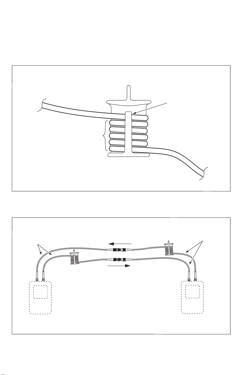
Using the Mandrels
Figures 1, 2, and 3 show how to use the mandrels.
Note
The mandrels are optimized for use on 3 mm jacketed fiber optic cable.
They may not produce the intended results on smaller-diameter cable.
Gray mandrel: 62.5/125 µm fiber
µ
Red mandrel: 50/125
Wrap 5 times
Figure 1. Wrapping the Patch Cord Around the Mandrel
m fiber
Place top wrap
in groove under
retainer
in grooves
Always use mandrels on
tester's OUTPUT
patch cord
apf02f.eps
Optical patch cords
(SC at tester ends)
Input
fiber
Output
fiber
Fiber tester
Figure 2. Using the Mandrels During Referencing
Adapters
Optical patch cords
(SC at tester ends)
Input
fiber
Output
fiber
Fiber tester
apf03f.eps
Page 3

Caution
Do not disconnect the patch cords from the tester or remove the mandrels
after referencing. If you do, you must set the reference again to ensure
valid measurements.
Short optical patch cords*
Fiber under test
Input
fiber
Output
fiber
Input
fiber
Output
fiber
Fiber tester
Fiber tester
The additional patch cords ensure that
*
measurements are consistent with
ANSI/TIA/EIA 526-14A, Method B.
Figure 3. Using Mandrels During Duplex Fiber Testing
apf04f.eps
Page 4

Contacting Fluke Networks
Visit the Fluke Networks website at www.flukenetworks.com. Send email to
support@flukenetworks.com.
To call us:
• Australia: 61 (2) 8850-3333 or 61 3 9329 0244
• Beijing: 86 (10) 6512-3435
• Brazil: 11 3044 1277
• Canada: 1-800-363-5853
• Europe: +44 1923 281 300
• Hong Kong: 852 2721-3228
• Japan: +81-3-3434-0181
• Korea: 82 2 539-6311
• Singapore: +65-6738-5655
• Taiwan: (886) 2-227-83199
• USA: 1-800-283-5853
• Anywhere in the world: +1-425-446-4519
Visit our website for a complete list of phone numbers.
LIMITED WARRANTY & LIMITATION OF LIABILITY
Fluke Networks products will be free from defects in material and workmanship for one
year from the date of purchase. Parts, accessories, product repairs, and services are
warranted for 90 days. This warranty does not cover disposable batteries, cable connector
tabs, cable insulation-displacement connectors, or damage from accident, neglect,
misuse, alteration, contamination, or abnormal conditions of operation or handling.
Resellers are not authorized to extend any other warranty on Fluke Networks’ behalf. To
obtain service during the warranty period, contact your nearest Fluke Networks
authorized service center to obtain return authorization information, then send your
defective product to that Service Center with a description of the problem.
THIS WARRANTY IS YOUR ONLY REMEDY. NO OTHER WARRANTIES, SUCH AS FITNESS
FOR A PARTICULAR PURPOSE, ARE EXPRESSED OR IMPLIED. FLUKE NETWORKS IS NOT
LIABLE FOR ANY SPECIAL, INDIRECT, INCIDENTAL OR CONSEQUENTIAL DAMAGES OR
LOSSES, ARISING FROM ANY CAUSE OR THEORY. Since some states or countries do not
allow the exclusion or limitation of an implied warranty or of incidental or consequential
damages, this limitation of liability may not apply to you.
6/01
Fluke Networks
PO Box 777
Everett, WA 98206-0777
USA
 Loading...