

Page 1

molstic-S™
Engineered Mounting Systems
for molbloc-S
Operation and Maintenance Manual
®
Mass Flow Elements
© 2004-2007 DH Instruments, a Fluke Company
Page 2
Do not exceed the maximum operating pressure of the molbox: 600 kPaa (87 psia) for molbox A700K;
250 kPaa (36 psia) for molbox A350K.
High pressure gases are potentially hazardous. Energy stored in these gases can be released
unexpectedly and with extreme force. High pressure systems should be assembled and operated only
by personnel who have been instructed in proper safety practices.
© 2004-2007 DH Instruments, a Fluke Company All rights reserved.
Information in this document is subject to change without notice. No part of this document may be reproduced or transmitted in any
form or by any means, electronic or mechanical, for any purpose, without the express written permission of DH Instruments, a
Fluke Company 4765 East Beautiful Lane Phoenix AZ 85044-5318 USA.
DH Instruments makes sincere efforts to ensure the accuracy and quality of its’ published materials; however, no warranty,
expressed or implied, is provided. DH Instruments disclaims any responsibility or liability for any direct or indirect damages
resulting from the use of the information in this manual or products described in it. Mention of any product does not constitute an
endorsement by DH Instruments of that product. This manual was originally composed in English and was subsequently translated
into other languages. The fidelity of the translation cannot be guaranteed. In case of conflict between the English version and other
language versions, the English version predominates.
Products described in this manual are manufactured under international patents and one or more of the following U.S. patents:
5,142,483, 5,257,640, 5,331,838, 5,445,035. Other U.S. and international patents pending.
DH Instruments, DH, DHI, molbloc, molbloc-L, molbloc_S, molbox1, molstic, molstic-L and molstic-S, are trademarks, registered
and otherwise, of DH Instruments, a Fluke Company.
VCR is a registered trademark of the Swagelok Company.
Viton is a registered trademarks of DuPont deNemours Company.
Document No. 550130a
041022
Printed in the USA.
© 2004-2007 DH Instruments, a Fluke Company
Page 3

TABLE OF CONTENTS
T
AABBLLEE OOFF
T
C
OONNTTEENNTTS
C
S
TABLE OF CONTENTS ...............................................................I
TABLES.................................................................................III
FIGURES................................................................................III
1. INTRODUCTION ................................................................. 1
1.1 PRODUCT OVERVIEW ...........................................................................................................................1
1.2 SPECIFICATIONS...................................................................................................................................1
1.2.1 GENERAL SPECIFICATIONS.......................................................................................................................1
1.2.2 COMPONENT IDENTIFICATION OF THE AVAILABLE MOLSTIC-S CONFIGURATIONS........................2
1.2.2.1 MOLSTIC-S, SINGLE 1/4 IN., STANDARD CONFIGURATION................................................................2
1.2.2.2 MOLSTIC-S, SINGLE 1/2 IN., STANDARD CONFIGURATION................................................................3
1.2.2.3 MOLSTIC-S, DUAL 1/4 IN., STANDARD CONFIGURATION....................................................................4
1.2.2.4 MOLSTIC-S, DUAL 1/2 IN., STANDARD CONFIGURATION....................................................................5
1.2.2.5 MOLSTIC-S, SINGLE 1/4 IN., WITH REGULATION .................................................................................6
1.2.2.6 MOLSTIC-S, SINGLE 1/2 IN., WITH REGULATION .................................................................................7
1.2.2.7 MOLSTIC-S, DUAL 1/4 IN., WITH REGULATION.....................................................................................8
1.2.2.8 MOLSTIC-S, DUAL 1/2 IN., WITH REGULATION.....................................................................................9
1.2.2.9 MOLSTIC-S, SINGLE 1/4 IN., WITH LOW- OR MID- FLOW METERING VALVE ..................................10
1.2.2.10 MOLSTIC-S, DUAL 1/4 IN., WITH LOW- OR MID- FLOW METERING VALVE......................................11
1.2.2.11 MOLSTIC-S, SINGLE 1/4 IN., WITH LOW- OR MID- FLOW METERING
1.2.2.12 MOLSTIC-S, DUAL 1/4 IN., WITH LOW- OR MID- FLOW METERING VALVE AND REGULATION.....13
VALVE AND REGULATION.....................................................................................................................
12
2. INSTALLATION ................................................................ 15
2.1 UNPACKING AND INSPECTION..........................................................................................................15
2.1.1 REMOVING FROM PACKAGING ...............................................................................................................15
2.1.2 INSPECTING CONTENTS...........................................................................................................................15
2.1.2.1 ACCESSORIES INCLUDED WITH MOLSTIC-S SHIPMENTS ...............................................................15
2.2 SITE REQUIREMENTS..........................................................................................................................16
2.3 INITIAL SETUP......................................................................................................................................16
2.3.1 PREPARATION FOR OPERATION ............................................................................................................16
2.3.2 INSTALLATION AND SWAPPING OF MOLBLOC-S.................................................................................16
2.3.2.1 REPLACING VCR INLET FLANGES ON MOLBLOC-S (AS REQUIRED) ..............................................16
2.3.2.2 INSTALLATION OF MOLBLOC-S ONTO MOLSTIC-S............................................................................18
2.4 MOLSTIC-S INTERCONNECTIONS .....................................................................................................20
2.4.1 GAS SUPPLY CONNECTIONS TO MOLSTIC-S........................................................................................20
2.4.1.1 MOLSTIC-S USE WITH DHI SUPPLIED REGULATORS .......................................................................21
2.4.1.2 MOLSTIC-S USE WITH REGULATORS NOT SUPPLIED BY DHI.........................................................22
2.4.2 INLET CONNECTION - MOLSTIC-S USE WITH DUT UPSTREAM...........................................................22
2.4.3 INLET CONNECTION - MOLSTIC-S USE WITH DUT DOWNSTREAM....................................................24
2.4.4 OUTLET CONNECTION - MOLBLOC-S OUTLET CONNECTION ............................................................24
2.5 CONNECTING, DISCONNECTING AND MOUNTING MOLBLOC-S™
WITH ISO-KF STYLE VACUUM FLANGE (MOLBLOC-S OUTLET FITTING).....................................
2.5.1 ISO-KF STYLE VACUUM FLANGE FITTINGS...........................................................................................24
2.5.2 MAKING AND BREAKING PROCEDURE FOR MOLBLOC-S ISO-KF
VACUUM FLANGE CONNECTION.............................................................................................................
2.5.2.1 MOLSTIC-S USE WITH DUT UPSTREAM..............................................................................................25
2.5.2.2 MOLSTIC-S USE WITH DUT DOWNSTREAM .......................................................................................25
24
25
Page I © 2004-2007 DH Instruments, a Fluke Company
Page 4

MOLSTIC-S™ OPERATION AND MAINTENANCE MANUAL
3. MOLSTIC-S OPERATION ................................................... 29
3.1 SYSTEM PRESSURIZATION AND REGULATOR ADJUSTMENT
– PRESSURE REDUCING REGULATOR.............................................................................................
3.1.1 SYSTEM PRESSURIZAION........................................................................................................................29
3.1.2 REGULATOR MAXIMUM PRESSURE ADJUSTMENT..............................................................................30
3.1.3 PRESSURE REDUCING REGULATOR ADJUSTMENT............................................................................30
29
3.2 SYSTEM PRESSURIZATION AND REGULATOR ADJUSTMENT
– BACK PRESSURE REGULATOR......................................................................................................
3.2.1 SYSTEM PRESSURIZATION......................................................................................................................31
3.2.2 BACK PRESSURE REGULATOR MAXIMUM PRESSURE ADJUSTMENT .............................................31
3.2.3 LOCKING THE BACK PRESSURE REGULATOR ADJUSTMENT (OPTIONAL).....................................31
3.2.4 BACK PRESSURE REGULATOR OPERATION........................................................................................31
30
3.3 LEAK CHECK RECOMMENDATIONS..................................................................................................32
3.4 MOLSTIC-S FLOW CONTROL .............................................................................................................32
3.4.1 DUT WITH FLOW CONTROL CAPABILITY...............................................................................................32
3.4.2 DUT WITHOUT FLOW CONTROL CAPABILITY .......................................................................................33
3.4.2.1 FLOW CONTROL USING METERING VALVES.....................................................................................33
3.4.2.2 FLOW CONTROL USING THE PRESSURE REGULATOR....................................................................33
4. OPTIONS AND UPGRADES................................................ 35
4.1 REGULATOR UPGRADE TO MOLSTIC-S...........................................................................................35
4.2 UPGRADE OF MOLSTIC-S WITH 1/4 IN. METERING VALVE ............................................................35
4.3 UPGRADE OF SINGLE MOLSTIC-S TO DUAL CHANNEL.................................................................35
5. MOLSTIC-S MAINTENANCE AND RECOMMENDATIONS ........ 37
5.1 FILTER CLEANING...............................................................................................................................37
5.2 HANDLING ............................................................................................................................................37
© 2004-2007 DH Instruments, a Fluke Company Page II
Page 5

TABLES & FIGURES
T
AABBLLEES
T
Table 1. Accessory Kit, 1/4 in. molstic-S versions, P/N 401938................................................................ 15
Table 2. Accessory Kit, 1/2 in. molstic-S versions, P/N 401939................................................................ 15
Table 3. molbloc-S Adaptor Kits ................................................................................................................26
Table 4. Metering Valve Use with molbloc-S.............................................................................................35
F
IIGGUURREES
F
Figure 1. molstic-S, Single 1/4 in., Standard Configuration.........................................................................2
Figure 2. molstic-S, Single 1/2 in., Standard Configuration.........................................................................3
Figure 3. molstic-S, Dual 1/4 in., Standard Configuration............................................................................4
Figure 4. molstic-S, Dual 1/2 in., Standard Configuration............................................................................5
Figure 5. molstic-S, Single 1/4 in., with Regulation .....................................................................................6
Figure 6. molstic-S, Single 1/2 in., with Regulation .....................................................................................7
Figure 7. molstic-S, Dual 1/4 in., with Regulation........................................................................................8
Figure 8. molstic-S, Dual 1/2 in., with Regulation........................................................................................9
Figure 9. molstic-S, Single 1/4 in., with Low- or Mid-Flow Metering Valve................................................10
Figure 10. molstic-S, Dual 1/4 in., with Low- or Mid-Flow Metering Valve ................................................11
Figure 11. molstic-S, Single 1/4 in., with Low- or Mid-Flow Metering Valve and Regulation ....................12
Figure 12. molstic-S, Dual 1/4 in., with Low- or Mid-Flow Metering Valve and Regulation.......................13
Figure 13. Replacing molbloc-S Flanges...................................................................................................17
Figure 14. Installation of molbloc-S onto molstic-S....................................................................................18
Figure 15. molbloc-S VCR Face Seal Connection.....................................................................................19
Figure 16. molstic-S with Supplied Regulator............................................................................................21
Figure 17. molstic-S with Supply Only Platform.........................................................................................21
Figure 18. molstic-S with DUT Upstream...................................................................................................23
Figure 19. molbloc-S with ISO-KF Style Flange ........................................................................................24
Figure 20. ISO-KF Style Flange.................................................................................................................25
Figure 21. molstic-S with DUT Upstream...................................................................................................26
Figure 22. Metering Valve..........................................................................................................................35
S
S
Page III © 2004-2007 DH Instruments, a Fluke Company
Page 6

MOLSTIC-S™ OPERATION AND MAINTENANCE MANUAL
N
N
OOTTEES
S
© 2004-2007 DH Instruments, a Fluke Company Page IV
Page 7
1. INTRODUCTION
.
11.
IINNTTRROODDUUCCTTIIOONN
1.1 PRODUCT OVERVIEW
The molstic-S™ provides an engineered solution to the practical issues of mounting the molbloc-S® mass
flow elements, connecting a gas supply, regulating the pressure and connecting the device to be tested.
Highest quality components are integrated into a modular, convenient, compact assembly.
Depending on the variation, the molstic-S provides mounting locations and the necessary hardware for up
to two molbloc-S elements with 48 mm square bodies. It can be used for testing DUT’s in either the
upstream or downstream position. By utilizing the available accessories, the molstic-S allows for the
simultaneous use of two molbloc-S elements (plumbed in parallel with downstream tee assembly
P/N 401884) in order to obtain additional flow range capacity. The optional pressure-reducing regulator
kits (P/Ns 401880 and 401881) are available for mounting and use directly on the molstic-S in order to
provide pressure control capability to the user.
Calibration test devices that are capable of controlling flow must be installed upstream of the molbloc-S if
they are to be tested in “control mode”. Use the molstic-S in conjunction with the appropriate
molstic-S Supply Assembly (P/N 401876 or 401877) when calibrating this type of device.
In order to provide flexibility, the molstic-S is supplied wit h 50 cm of PFA tubi ng (e ither 1/ 4 in. or 1/2 in. O D) for
use in making connections to the gas supply or to the DUT. Ensure that the safe operating pressure of 1 MPa
(150 psig) is not exceeded when using this tubing.
1.2 SPECIFICATIONS
1.2.1 GENERAL SPECIFICATIONS
1/4 in. molstic-S 1/2 in. molstic-S
Electrical Power Requirements
Maximum Supply Pressure
(applied to molstic-S plumbing)
Operating Temperature Range
Storage Temperature Range
Platform Dimensions (L x W x H)
(without molblocs)
Weight (without molblocs)
None required. None required.
0.7 MPa (100 psig) 0.7 MPa (100 psig)
15 to 35 °C 15 to 35 °C
- 20 to 70 °C -20 to 70 °C
585 mm x 176 mm x 70 mm
(23.0 in. x 7.0 in. x 2.75 in.)
2.5 to 6 kg (5.5 to 13.2 lb.)
depending upon configuration
585 mm x 176 mm x 70 mm
(23.0 in. x 7.0 in. x 2.75 in.)
3 to 6 kg (6.6 to 13.2 lb.)
depending upon configuration
Page 1 © 2004-2007 DH Instruments, a Fluke Company
Page 8

MOLSTIC-S™ OPERATION AND MAINTENANCE MANUAL
1.2.2 COMPONENT IDENTIFICATION OF THE AVAILABLE MOLSTIC-S CONFIGURATIONS
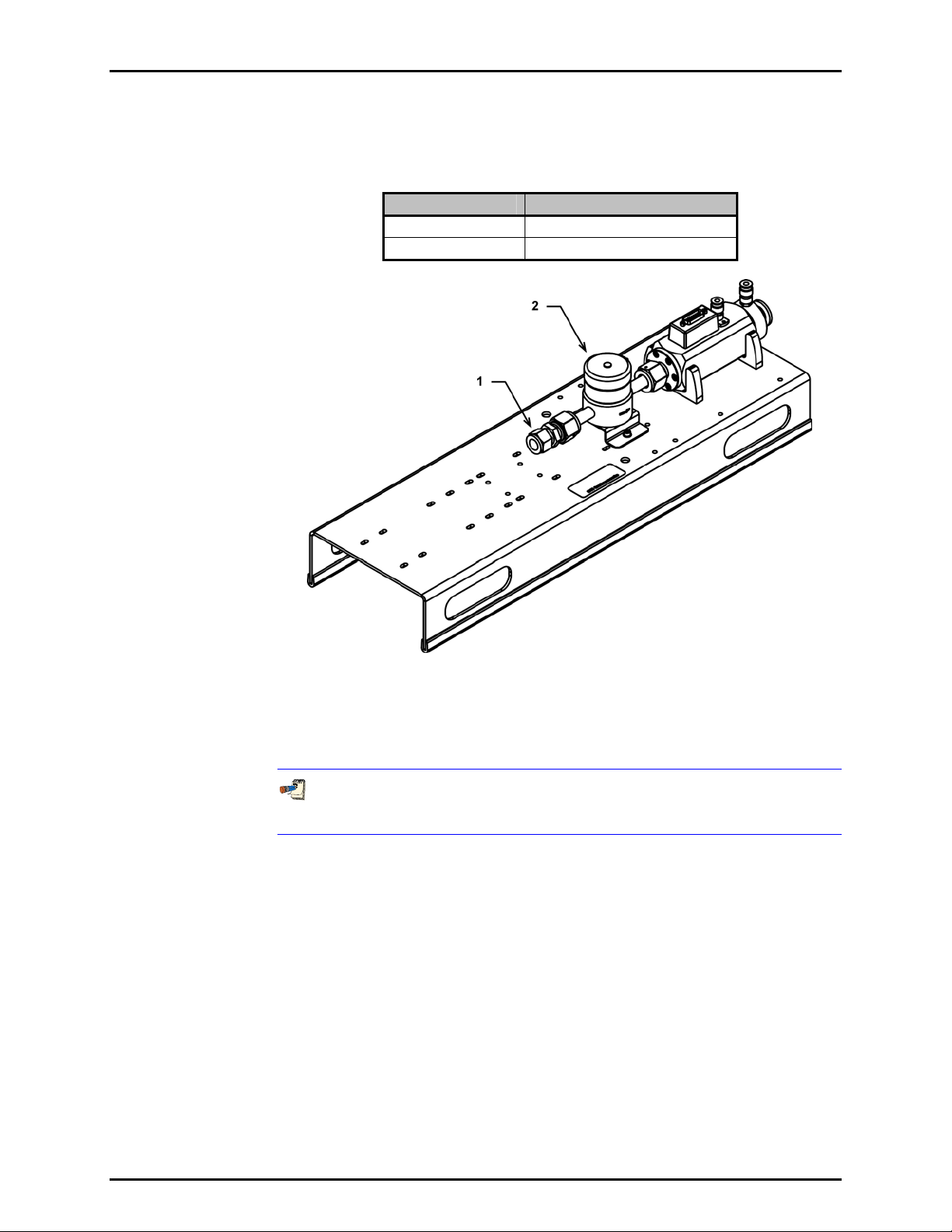
1.2.2.1 MOLSTIC-S, SINGLE 1/4 IN., STANDARD
CONFIGURATION
ORDERING INFO DESCRIPTION
P/N FAM0009 molstic-S, molstic for molbloc-S
Option -01-1 Single Channel, 1/4 in. Plumbing
Figure 1. molstic-S, Single 1/4 in.,
Standard Configuration
1. Inlet adaptor – 1/4 in. tube x 1/4 in. male VCR
2. Particulate filter, 2 micron
3. Flow shut-off/metering valve
50 cm of clear PFA tubing is included with the molstic-S in order to provide
versatility in the connection of DUT’s and inlet supply plumbing.
© 2004-2007 DH Instruments, a Fluke Company Page 2
Page 9
1. INTRODUCTION
1.2.2.2 MOLSTIC-S, SINGLE 1/2 IN., STANDARD
CONFIGURATION
ORDERING INFO DESCRIPTION
P/N FAM0009 molstic-S, molstic for molbloc-S
Option -01-2 Single Channel, 1/2 in. Plumbing
Figure 2. molstic-S, Single 1/2 in.,
Standard Configuration
1. Inlet adaptor – 1/2 in. tube x 1/2 in. male VCR
2. Flow shut-off/metering valve
50 cm of clear PFA tubing is included with the molstic-S in order to provide
versatility in the connection of DUT’s and inlet supply plumbing.
Page 3 © 2004-2007 DH Instruments, a Fluke Company
Page 10
MOLSTIC-S™ OPERATION AND MAINTENANCE MANUAL
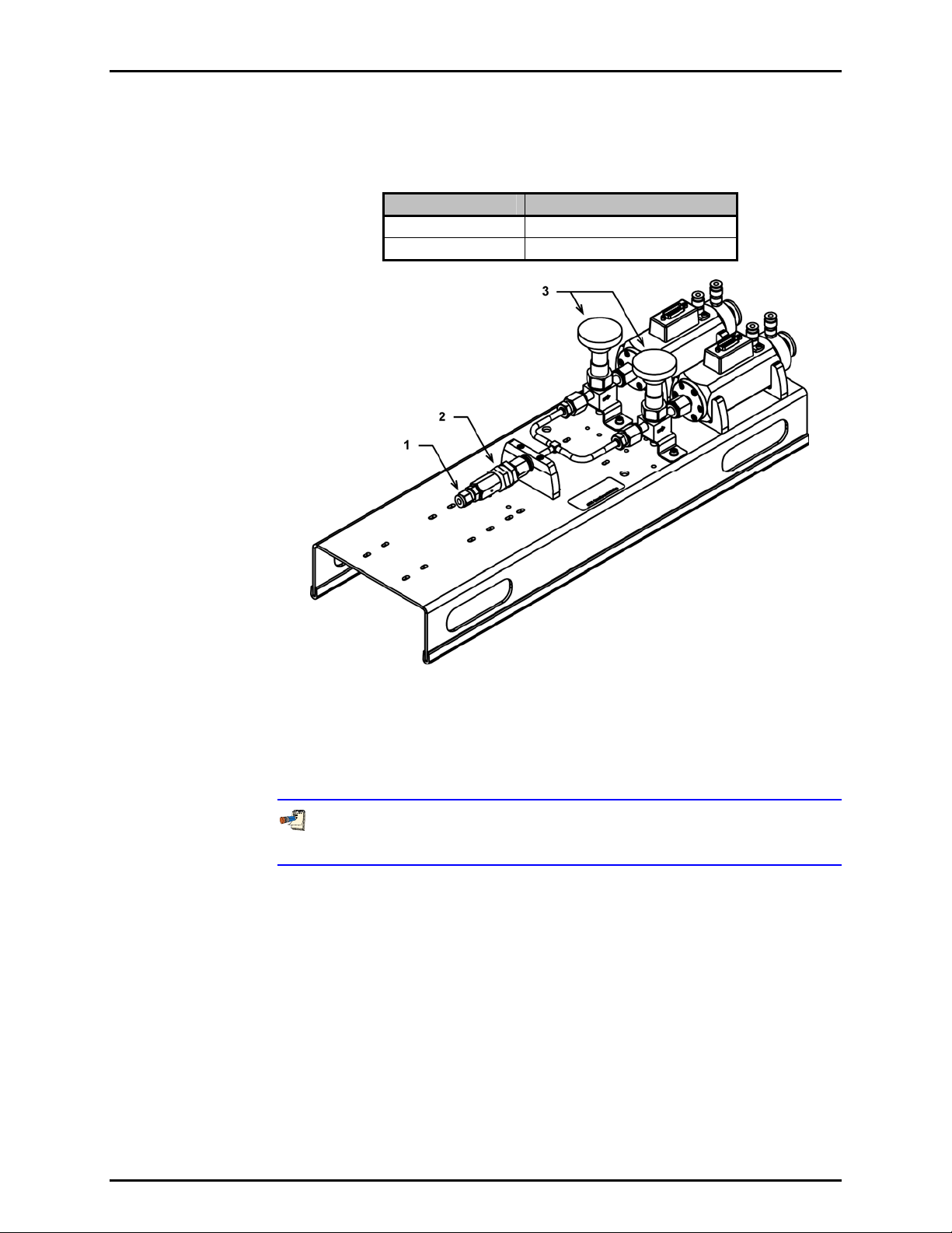
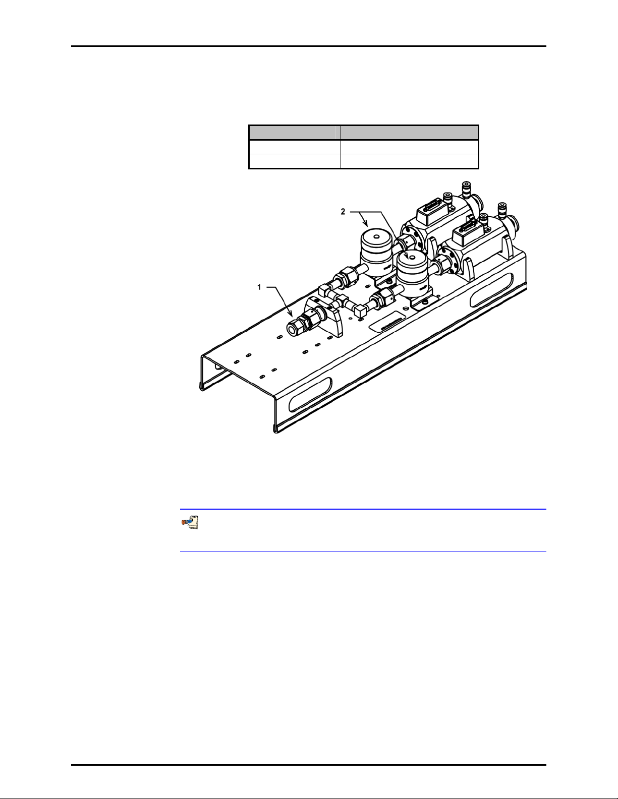
1.2.2.3 MOLSTIC-S, DUAL 1/4 IN., STANDARD
CONFIGURATION
ORDERING INFO DESCRIPTION
P/N FAM0009 molstic-S, molstic for molbloc-S
Option -01-3 Dual Channel, 1/4 in. Plumbing
Figure 3. molstic-S, Dual 1/4 in.,
Standard Configuration
1. Inlet adaptor – 1/4 in. tube x 1/4 in. male VCR
2. Particulate filter, 2 micron
3. Flow shut-off/metering valve, 2 ea.
50 cm of clear PFA tubing is included with the molstic-S in order to provide
versatility in the connection of DUT’s and inlet supply plumbing.
© 2004-2007 DH Instruments, a Fluke Company Page 4
Page 11
1. INTRODUCTION
1.2.2.4 MOLSTIC-S, DUAL 1/2 IN., STANDARD
CONFIGURATION
ORDERING INFO DESCRIPTION
P/N FAM0009 molstic-S, molstic for molbloc-S
Option -01-4 Dual Channel, 1/2 in. Plumbing
Figure 4. molstic-S, Dual 1/2 in.,
Standard Configuration
1. Inlet adaptor – 1/2 in. tube x 1/2 in. male VCR
2. Flow shut-off/flow metering valve, 2 ea.
50 cm of clear PFA tubing is included with the molstic-S in order to provide
versatility in the connection of DUT’s and inlet supply plumbing.
Page 5 © 2004-2007 DH Instruments, a Fluke Company
Page 12
MOLSTIC-S™ OPERATION AND MAINTENANCE MANUAL
1.2.2.5 MOLSTIC-S, SINGLE 1/4 IN., WITH REGULATION
ORDERING INFO DESCRIPTION
P/N FAM0009 molstic-S, molstic for molbloc-S
Option
-03-4 With 1/4 in. Back Pressure Regulator
-01-1 Single Channel, 1/4 in. Plumbing
-03-2 With 1/4 in. Pressure Reducing Regulator
Figure 5. molstic-S, Single 1/4 in.,
with Regulation
1. Inlet quick connect
(includes stem with 1/4 in. SWG, not shown)
2. Pressure reducing regulator/back pressure regulator
3. Particulate filter, 2 micron
4. Flow shut-off/metering valve
50 cm of clear PFA tubing is included with the molstic-S in order to provide
versatility in the connection of DUT’s and inlet supply plumbing.
© 2004-2007 DH Instruments, a Fluke Company Page 6
Page 13
1. INTRODUCTION
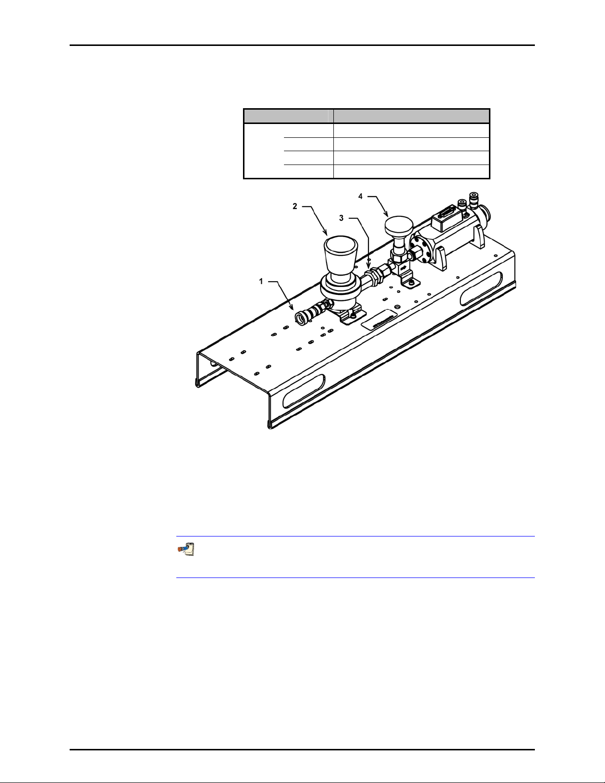
1.2.2.6 MOLSTIC-S, SINGLE 1/2 IN., WITH REGULATION
ORDERING INFO DESCRIPTION
P/N FAM0009 molstic-S, molstic for molbloc-S
Option
-03-5 With 1/2 in. Back Pressure Regulator
-01-2 Single Channel, 1/2 in. Plumbing
-03-3 With 1/2 in. Pressure Reducing Regulator
Figure 6. molstic-S, Single 1/2 in.,
with Regulation
1. Inlet quick connect
(includes stem with 1/2 in. SWG, not shown)
2. Pressure reducing regulator/back pressure regulator
50 cm of clear PFA tubing is included with the molstic-S in order to provide
versatility in the connection of DUT’s and inlet supply plumbing.
3. Flow shut-off/metering valve
Page 7 © 2004-2007 DH Instruments, a Fluke Company
Page 14
MOLSTIC-S™ OPERATION AND MAINTENANCE MANUAL
1.2.2.7 MOLSTIC-S, DUAL 1/4 IN., WITH REGULATION
ORDERING INFO DESCRIPTION
P/N FAM0009 molstic-S, molstic for molbloc-S
Option
-03-4 With 1/4 in. Back Pressure Regulator
-01-3 Dual Channel, 1/4 in. Plumbing
-03-2 With 1/4 in. Pressure Reducing Regulator
Figure 7. molstic-S, Dual 1/4 in.,
with Regulation
1. Inlet quick connect
(includes stem with 1/4 in. SWG, not shown)
2. Pressure reducing regulator/back pressure regulator
3. Particulate filter, 2 micron
4. Flow shut-off/metering valve, 2 ea.
50 cm of clear PFA tubing is included with the molstic-S in order to provide
versatility in the connection of DUT’s and inlet supply plumbing.
© 2004-2007 DH Instruments, a Fluke Company Page 8
Page 15

1. INTRODUCTION
1.2.2.8 MOLSTIC-S, DUAL 1/2 IN., WITH REGULATION
ORDERING INFO DESCRIPTION
P/N FAM0009 molstic-S, molstic for molbloc-S
Option
-03-5 With 1/2 in. Back Pressure Regulator
-01-4 Dual Channel, 1/2 in. Plumbing
-03-3 With 1/2 in. Pressure Reducing Regulator
Figure 8. molstic-S, Dual 1/2 in.,
with Regulation
1. Inlet quick connect
(includes stem with 1/2 in. SWG, not shown)
2. Pressure reducing regulator/back pressure regulator
3. Flow shut-off/metering valve, 2 ea.
50 cm of clear PFA tubing is included with the molstic-S in order to provide
versatility in the connection of DUT’s and inlet supply plumbing.
Page 9 © 2004-2007 DH Instruments, a Fluke Company
Page 16

MOLSTIC-S™ OPERATION AND MAINTENANCE MANUAL
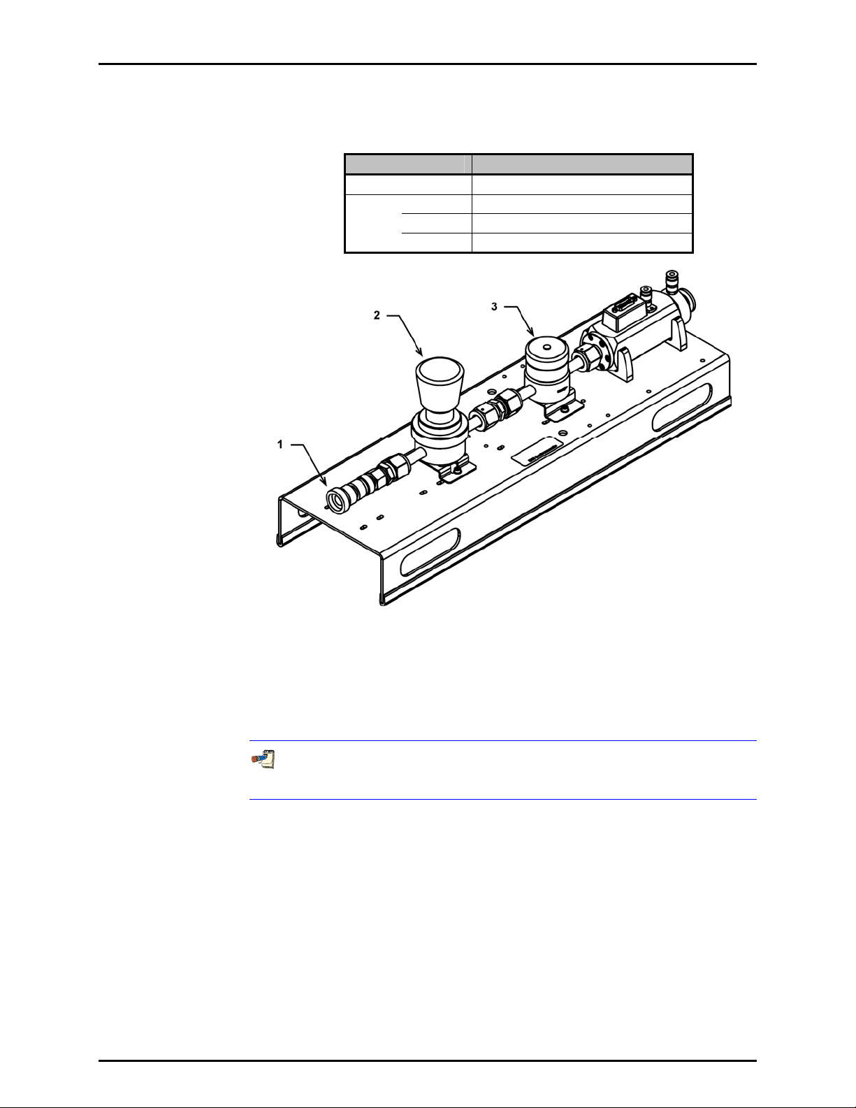
1.2.2.9 MOLSTIC-S, SINGLE 1/4 IN., WITH LOW- OR MIDFLOW METERING VALVE
ORDERING INFO DESCRIPTION
P/N FAM0009 molstic-S, molstic for molbloc-S
-01-1 Single Channel, 1/4 in. Plumbing
Option
-04-2 With 1/4 in. Low Flow Metering Valve
-04-3 With 1/4 in. Mid Flow Metering Valve
Figure 9. molstic-S, Single 1/4 in.,
with Low- or Mid-Flow Metering Valve
1. Inlet adaptor – 1/4 in. tube x 1/4 in. male VCR
2. Particulate filter, 2 micron
3. Precision flow metering valve
4. Flow shut-off/metering valve
50 cm of clear PFA tubing is included with the molstic-S in order to provide
versatility in the connection of DUT’s and inlet supply plumbing.
© 2004-2007 DH Instruments, a Fluke Company Page 10
Page 17

1. INTRODUCTION
1.2.2.10 MOLSTIC-S, DUAL 1/4 IN., WITH LOW- OR MID- FLOW METERING VALVE
ORDERING INFO DESCRIPTION
P/N FAM0009 molstic-S, molstic for molbloc-S
-01-3 Dual Channel, 1/4 in. Plumbing
Option
-04-2 With 1/4 in. Low Flow Metering Valve
-04-3 With 1/4 in. Mid Flow Metering Valve
Figure 10. molstic-S, Dual 1/4 in.,
with Low- or Mid-Flow Metering Valve
1. Inlet adaptor – 1/4 in. tube x 1/4 in. male VCR
2. Particulate filter, 2 micron
3. Precision flow metering valve
4. Flow shut-off/metering valve, 2 ea.
50 cm of clear PFA tubing is included with the molstic-S in order to provide
versatility in the connection of DUT’s and inlet supply plumbing.
Page 11 © 2004-2007 DH Instruments, a Fluke Company
Page 18

MOLSTIC-S™ OPERATION AND MAINTENANCE MANUAL
1.2.2.11 MOLSTIC-S, SINGLE 1/4 IN., WITH LOW- OR MIDFLOW METERING VALVE AND REGULATION
ORDERING INFO DESCRIPTION
P/N FAM0009 molstic-S, molstic for molbloc-S
-01-1 Single Channel, 1/4 in. Plumbing
-03-2 With 1/4 in. Pressure Reducing Regulator
Option
-03-4 With 1/4 in. Back Pressure Regulator
-04-2 With 1/4 in. Low Flow Metering Valve
-04-3 With 1/4 in. Mid Flow Metering Valve
Figure 11. molstic-S, Single 1/4 in.,
with Low- or Mid-Flow Metering Valve and Regulation
1. Inlet quick connect
(includes stem with 1/4 in. SWG, not shown)
2. Pressure reducing regulator/back pressure regulator
3. Particulate filter, 2 micron
4. Precision flow metering valve
5. Flow shut-off/flow metering valve
50 cm of clear PFA tubing is included with the molstic-S in order to provide
versatility in the connection of DUT’s and inlet supply plumbing.
© 2004-2007 DH Instruments, a Fluke Company Page 12
Page 19

1. INTRODUCTION
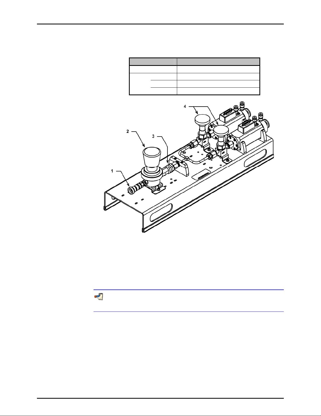
1.2.2.12 MOLSTIC-S, DUAL 1/4 IN., WITH LOW- OR MID- FLOW METERING VALVE AND REGULATION
ORDERING INFO DESCRIPTION
P/N FAM0009 molstic-S, molstic for molbloc-S
-01-3 Dual Channel, 1/4 in. Plumbing
-03-2 With 1/4 in. Pressure Reducing Regulator
Option
-03-4 With 1/4 in. Back Pressure Regulator
-04-2 With 1/4 in. Low Flow Metering Valve
-04-3 With 1/4 in. Mid Flow Metering Valve
Figure 12. molstic-S, Dual 1/4 in.,
with Low- or Mid-Flow Metering Valve and Regulation
1. Inlet quick connect
(includes stem with 1/4 in. SWG, not shown)
2. Pressure reducing regulator/back pressure regulator
3. Particulate filter, 2 micron
4. Precision flow metering valve
5. Flow shut-off/flow metering valve, 2 ea.
50 cm of clear PFA tubing is included with the molstic-S in order to provide
versatility in the connection of DUT’s and inlet supply plumbing.
Page 13 © 2004-2007 DH Instruments, a Fluke Company
Page 20

MOLSTIC-S™ OPERATION AND MAINTENANCE MANUAL
N
N
OOTTEES
S
© 2004-2007 DH Instruments, a Fluke Company Page 14
Page 21

2. INSTALLATION
.
22.
I
NNSSTTAALLLLAATTIIOON
I
N
2.1 UNPACKING AND INSPECTION
2.1.1 REMOVING FROM PACKAGING
The molstic-S is delivered, along with its standard accessories, in a corrugated container with
foam-in-place inserts.
Remove the molstic-S and its accessories from the shipping container and remove each item
from its protective plastic bag.
2.1.2 INSPECTING CONTENTS
Check that all items are present and that there are no visual indications of damage.
Each variation of the molstic-S mounting system is delivered with one of the following
accessory kits:
2.1.2.1 ACCESSORIES INCLUDED WITH MOLSTIC-S SHIPMENTS
Table 1. Accessory Kit, 1/4 in. molstic-S versions, P/N 401938
DESCRIPTION PART #
1 molstic-S™ Operation and Maintenance Manual 550130
1 16 mm ISO-KF Blanking Flange 103238
1 16 mm ISO-KF Centering Ring 101544
1 16 mm ISO-KF Overpressure Ring 103240
1 16 mm ISO-KF Clamp 102975
4 1/4 in. VCR Face Seal O-ring 102070
2 1/4 in. VCR Face Seal Gasket 102183
1 1/4 in. OD PFA Tubing, 50 cm 101450-Z
Table 2. Accessory Kit, 1/2 in. molstic-S versions, P/N 401939
DESCRIPTION PART #
1 molstic-S™ Operation and Maintenance Manual 550130
1 16 mm ISO-KF Blanking Flange 103238
1 16 mm ISO-KF Centering Ring 101544
1 16 mm ISO-KF Overpressure Ring 103240
1 16 mm ISO-KF Clamp 102975
4 1/2 in. VCR Face Seal O-ring 102912
2 1/2 in. VCR Face Seal Gasket 102923
1 1/2 in. OD PFA Tubing, 50 cm 103227-Z
Page 15 © 2004-2007 DH Instruments, a Fluke Company
Page 22

MOLSTIC-S™ OPERATION AND MAINTENANCE MANUAL
2.2 SITE REQUIREMENTS
The molstic-S should be installed on a stable work surface at a convenient height. The bottom edge of
the molstic-S platform has a rubberized material that will protect the work surface from marring and
scratching. This will also prevent the molstic-S from slipping on smooth surfaces.
When installing the molstic-S, consideration should be given to where the gas supply to molbloc-S will be
located. Minimize the length of supply plumbing and keep it organized so that it does not cross the area
in which the operator will be working.
2.3 INITIAL SETUP
2.3.1 PREPARATION FOR OPERATION
Remove the plastic protective caps from the supply and outlet ports of the molstic-S.
Determine whether the DUT will be installed upstream or downstream of the molstic-S.
DUTs that have built in flow control capability, such as MFCs, (and are to be tested in
flow control mode) must be tested in the upstream location. Install this type of DUT
Make the inlet gas supply and DUT connections per the instructions below.
upstream of the molbloc-S only.
2.3.2 INSTALLATION AND SWAPPING OF MOLBLOC-S
Typically the molstic-S mounting syste m configu red with 1/4 in. plumbi ng is used to ac commodat e
the molbloc-S elements with 48 mm square bodies and 1/4 in. male VCR
designated 1E2-S and smaller. In some cases, when ru nning “low” flows in sub-atm ospheric m ode,
it might be desirable to use molbloc- S elements that have 1/2 in. VCR inlet fittings on the 1/4 in.
molstic-S mounting system. Use the inlet flange conversion kit, P/N 401935.
The molstic-S mounting system configured with 1/2 in. plumbing can accommodate any
molbloc-S elements with 48 mm s qua re bo dies , up to 2E3- S. In ord er to be us ed on th is mols tic ,
any molbloc-S element designated 1E2-S and smaller must have its 1/4 in. VCR inlet fitting
replaced with the 1/2 in. VCR end flange through the use of conversion kit P/N 401936.
2.3.2.1 REPLACING VCR INLET FLANGES ON MOLBLOC-S (AS REQUIRED)
Use the following procedure to replace the VCR inlet flange on the molbloc-S
elements, using conversion kit P/N 401935 or 401936.
®
inlet fittings,
© 2004-2007 DH Instruments, a Fluke Company Page 16
Page 23

2. INSTALLATION
1. Body screw, 6 ea.
2. Inlet flange
3. O-ring, P/N 2-022
Figure 13. Replacing molbloc-S Flanges
Using a 3 mm hex wrench, remove and preserve the socket head caps
screws that retain the existing VCR inlet end flange. DO NOT remove the
downstream end flange.
Preserve the end flange face seal, Viton® O-ring (DHI P/N 102221) Parker
P/N 2-022, for use with the new flange. Be careful not to damage this seal in
any way, as a leak can result which will cause errors during flow measurement.
Position the replacement VCR inlet flange on the end of molbloc-S, making
sure that the flange seal is in its proper location, and be sure not to “pinch”
the seal between the flange and body.
Thread each of the socket head caps screws into the body, but leave loose
enough to allow adjustment in the flange’s final position.
Tighten each of the screws in a “star” pattern a little at a time. Finish by
tightening to a torque value of 3 Nm on each screw.
Page 17 © 2004-2007 DH Instruments, a Fluke Company
Page 24

MOLSTIC-S™ OPERATION AND MAINTENANCE MANUAL
2.3.2.2 INSTALLATION OF MOLBLOC-S ONTO MOLSTIC-S
Place the molbloc-S into the cradles on the molstic-S, making sure that its
orientation matches the flow direction of the molstic-S.
Figure 14. Installation of molbloc-S onto molstic-S
2.3.2.2.1 molbloc-S Inlet Fitting Connection
The inlet fitting to the molbloc-S utilizes the VCR face seal type connection. Use the
following procedure for connecting and disconnecting molbloc-S elements with
VCR connections.
Connecting, Disconnecting and Mounting molbloc-S with VCR Face Seal
Fittings (molbloc-S Inlet Fitting)
In making the molbloc-S inlet flow connection, always use soft O-rings. They allow
a leak free connection to be accomplished with minimal torque, and they provide
a source of flexibility between the molbloc-S and elements to which it is connected,
protecting the molbloc-S from mounting stresses.
Use the following O-ring seal for making molbloc-S VCR connections:
VCR FACE
SEAL SIZE
1/4 in. 102070 2-202 Fluorocarbon rubber (FKM), Viton
1/2 in. 102912 2-207 Fluorocarbon rubber (FKM), Viton
DHI
PART NO.
PART NO.
PARKER SEAL GROUP,
O-RING DIVISION
COMPOSITION
© 2004-2007 DH Instruments, a Fluke Company Page 18
Page 25

2. INSTALLATION
Making and Breaking Procedure for molbloc-S VCR Face Seal Connection
n Install the recommended soft O-ring
securely against the sealing surface
in the nut of the mating fitting.
o Align the mating nut with the
molbloc’s male VCR fitting and
thread the nut onto the fitting. Hold
the molbloc-S with your hand, rotate
the nut until resistance is felt when
the O-ring begins to compress.
p Holding the molbloc-S with your
hand, tighten the nut an additional
1/2 turn. A wrench may be used on
Figure 15. molbloc-S VCR Face Seal
Connection
the nut if desired, but do not tighten
beyond one half turn. If more than one half turn is needed to make a leak
free connection, the O-ring may be damaged and should be replaced.
q To break the fitting, hold the molbloc-S with your hand and loosen the nut
until it is completely backed off.
Never use wrenches to hold the molbloc-S body.
2.3.2.2.2 molbloc-S Connections to molbox
For the pressure connections, use the molbox® to molbloc-S pressure tubes
(P/N 401125) supplied with the molbox. Following the color coding on the
pressure lines, connect the upstream (HI) molbox rear panel quick connector to
the upstream port of the molbloc-S and the downstream (LO) quick connector to
the downstream port. Push firmly on the quick connect until it clicks into place to
assure that the connection is completed.
For the electrical/data connection, use the molbox to molbloc-S connection cable
(P/N 102096, or 102096-CE) supplied with the molbox. Connect the cable to the
15-pin electrical/data connector on the molbloc-S and then to the molbox rear
panel connector labeled ”molbloc”.
2.3.2.2.3 Swapping molbloc-S Elements onto molstic-S
To change the molbloc-S element, break the VCR face seal inlet connection.
The O-ring seal is reusable but should be examined for damage that could cause
a leak. Place the new molbloc-S into the cradles, and make the VCR face
seal connection.
Page 19 © 2004-2007 DH Instruments, a Fluke Company
Page 26

MOLSTIC-S™ OPERATION AND MAINTENANCE MANUAL
2.4 MOLSTIC-S INTERCONNECTIONS
2.4.1 GAS SUPPLY CONNECTIONS TO MOLSTIC-S
Determine the maximum operating pressure range of your molbox RPTs prior to connecting a
gas source to your molstic-S.
See the molbox calibration report to determine the pressure range of the Reference
Pressure Transducers (RPTs) in the molbox you are using. molbox1-A700K has a maximum
operating pressure of 600 kPaa (87 psia), and molbox1-A350K has a maximum operating
pressure of 250 kPaa (36 psia).
If a contaminated device under test is located upstream of the molbloc, contaminants
may flow from the device under test to the molbloc-S and alter its calibration. If the
device under test must be connected upstream of the molbloc-S, be sure it is clean before
flowing and consider installing a filter between the DUT and the molbloc.
The gas supply to the molstic-S has the following requirements:
• The gas supply must be clean and free of particulate contamination in order to avoid
damage to the molbloc.
• For correct measurements, the gas must be of the same species as that selected by the
molbox [GAS] function. Use of ambient ai r (moist air) i s supp orted by the molbox. G as pu rity
will affect the measurement uncertainty of the flow measurements as molbox uses the
thermodynamic properties of the flowing gas in its calculations. Use gases with purity of
99.9 % or better for molbloc measurements.
• The pressure must be regulated and stable within the limits of the molbloc-S calibration
pressure range, and low enough to avoid over-pressurization of the molbox.
• The pressure must not exceed the maximum operating pressure rating of the RPTs in
the molbox. See the back panel label of the molbox to determine the maximum
operating pressure allowed. Verification of the pressure rating should be obtained
by examination of the calibration range on the molbox certification of calibration.
© 2004-2007 DH Instruments, a Fluke Company Page 20
Page 27

2. INSTALLATION
2.4.1.1 MOLSTIC-S USE WITH DHI SUPPLIED REGULATORS
The inlet gas supply to the molstic-S must be suitably regulated prior to
connection to the inlet of the molbloc-S plumbing. The molstic-S is available with
the proper pressure reducing regulator integrated, or it can be added in the field
using the optional regulator upgrade kits that are available in 1/4 in. or 1/2 in.,
P/N 401880 and 401881, respectively.
Figure 16. molstic-S with Supplied Regulator
DHI also offers the supply only platform that includes the regulator with a quick
connect inlet, and a shut-off/metering valve on the outlet. P/Ns 401876 and
401877 are compatible with the 1/4 in. and 1/2 in. molstic-S, and allow additional
flexibility in the plumbing location of the DUT. The regulators supplied by DHI
were chosen for their superior performance and compatibility with the molbloc-S
operation methods.
Figure 17. molstic-S with Supply Only Platform
Page 21 © 2004-2007 DH Instruments, a Fluke Company
Page 28

MOLSTIC-S™ OPERATION AND MAINTENANCE MANUAL
Set regulator outlet pressure to minimum: Rotate the knob of the
pressure reducing regulator in the counterclockwise direction until the spring
force of the diaphragm is relieved. Insure that the shut-off valve(s) is in the
closed position.
Be sure that the molstic-S Supply Assembly or molstic-S shut-off
valve(s) is closed before connecting the quick connector stem to the
quick connector body (located on the regulator’s inlet).
Connect the gas supply: Connect the gas supply to the quick connector
stem (1/4 in. or 1/2 in. tube). The gas supply pressure should not exceed
1.7 MPa (250 psig). Insert the stem into the quick connect body.
2.4.1.2 MOLSTIC-S USE WITH REGULATORS NOT SUPPLIED BY DHI
The inlet gas supply to the molstic-S must be suitably regulated prior to
connection to the inlet of the molbloc-S plumbing. In addition, a shut-off valve
should be used downstream of the regulator in order to allow for system leak
testing. The pressure reducing regulators supplied by DHI are selected for the
following characteristics:
• High quality
• High sensitivity and stability
• Outlet (control) pressure range: 0 to 100 psig
• Non-venting – does not relieve control pressure outside of plumbing
• Low droop (change in control pressure with change in flow rate)
• Low inlet pressure effect (change in control for a given change in supply pressure)
• Flow capacity – capability to flow to maximum required flow rate
Set regulator outlet pressure to minimum: Rotate the knob of the user
supplied pressure reducing regulator in the counterclockwise direction until
the spring force of the diaphragm is relieved. Insure that the shut-off valve(s)
is in the closed position.
Connect the gas supply: Connect the gas supply to the pressure regulator’s
inlet port using suitable means and compatible fittings. The gas supply
pressure should not exceed the regulator’s maximum operating pressure.
2.4.2 INLET CONNECTION - MOLSTIC-S USE WITH DUT UPSTREAM
DUTs that have built in flow control capability, such as MFCs, (and are to be tested in
flow control mode) must be tested in the upstream location. Install this type of DUT
upstream of the molbloc-S only.
© 2004-2007 DH Instruments, a Fluke Company Page 22
Page 29

2. INSTALLATION
Figure 18. molstic-S with DUT Upstream
Follow these guidelines when connecting the DUT to the upstream of the molstic-S:
• Inspect the DUT for contamination: When using the molstic-S with the DUT installed
upstream, as is required when calibrating flow devices that control flow, it is recommended
practice to inspect the DUT for any material that might contaminate either the molstic
plumbing or the molbloc-S elements installed on the molstic.
• Use inline particulate filters: Since the smaller molbloc-S elements that are compatible
with the 1/4 in. molstic-S have quite small passages, the 1/4 in. molstic-S comes with a
2 micron particulate filter. There is a filter kit available from DHI for use between the DUT
and the inlet of the 1/2 in. molstic-S, to protect the molbloc-S elements from particulate
contamination. (Consult factory for availability of 1/2 in. inline filter kit).
• Connect DUT to molstic-S inlet: Since there are so many types and sizes DUTs that
can be calibrated by the molbloc-S, and since there is no standardized dimension for the
DUT’s plumbing centerline to its base, the molstic-S was not designed to accommodate
the DUT directly on its platform. For the sake of flexibility, the molstic-S is supplied with
50 cm of PFA tubing to help make the inlet and outlet connections. Use of the adjustable
DUT stand (P/N 401934) will also facilitate the alignment of the centerline of the DUT’s
inlet plumbing connection with that of the molstic-S plumbing.
• Connect Gas Supply to DUT Inlet: Connect the gas supply to the DUT inlet per Section 2.4.1.
• Leak Check System Plumbing: Refer to Section 3 for leak check recommendations.
During system leak testing, be extremely careful not to apply pressure in excess of
the maximum operating pressure of the molbox: 600 kPaa (87 psia) for molbox1A700K, 250 kPaa (36 psia) for molbox1-A350K models!.
Page 23 © 2004-2007 DH Instruments, a Fluke Company
Page 30

MOLSTIC-S™ OPERATION AND MAINTENANCE MANUAL
2.4.3 INLET CONNECTION - MOLSTIC-S USE WITH DUT DOWNSTREAM
Connect the Gas Supply: Connect the gas supply to the inlet fitting of the molstic-S
using suitable means and compatible fittings. Following instructions in Section 2.4.1.
2.4.4 OUTLET CONNECTION - MOLBLOC-S OUTLET CONNECTION
The outlet fitting of the molbloc-S utilizes the ISO-KF Style vacuum flange. Use the following
procedure for connecting and disconnecting molbloc-S elements with ISO-KF Style connections.
Figure 19. molbloc-S with ISO-KF Style Flange
1. Flange, ISO-KF style, 16 mm
2.5 CONNECTING, DISCONNECTING AND MOUNTING
MOLBLOC-S
™
WITH ISO-KF STYLE VACUUM FLANGE
(MOLBLOC-S OUTLET FITTING)
2.5.1 ISO-KF STYLE VACUUM FLANGE FITTINGS
The outlet connection system on the molbloc-S body is the ISO-KF style vacuum flange. It
utilizes an internal centering ring, an external overpressure ring and clamp. The seal is
effected by the uniform application of pressure by the clamp on the 15° surface of the mating
stainless steel flanges. These mating flange surfaces compress a Viton O-ring that is held in
place by the centering ring. The overpressure ring keeps the O-ring in place, and maintains a
leak free connection when the system is subjected to internal pressures above vacuum level.
This connection is reusable, rotatable, and can operate leak free in vacuum applications up to
-8
Torr, and in positive pressures of 700 kPa (100 psig).
10
When performing a leak test of a plumbing system that contains the ISO-KF Style
Vacuum Flanges, do not exceed the maximum operating pressure of the molbox:
600 kPaa (87 psia) for molbox1-A700K, 250 kPaa (36 psia) for molbox1-A350K models.
© 2004-2007 DH Instruments, a Fluke Company Page 24
Page 31

2. INSTALLATION
2.5.2 MAKING AND BREAKING PROCEDURE FOR MOLBLOC-S
ISO-KF VACUUM FLANGE CONNECTION
n Place the over-pressure ring past
one of the ISO-KF flanges to be
mated.
o Place the centering ring into the
groove of the ISO-KF flange on the
outlet of the molbloc-S.
Align the mating flange against
molbloc’s ISO-KF flange, and close
the gap by hand.
Hold the flanges together and move
the overpressure ring directly over
the mated flanges.
Figure 20. ISO-KF Style Flange
Place the clamp around the mated flanges. Swing the clamp closed. If necessary
loosen the thumbscrew to allow the thrust washer and wing nut to fall into position
on top of the clamp. Fully tighten the wing nut by hand.
To break the fitting, hold the molbloc-S with your hand and loosen the wing
nut until the clamp can be separated. Remove the clamp, centering ring,
and overpressure ring.
Never use wrenches to hold the molbloc-S body or tighten the wing nut.
2.5.2.1 MOLSTIC-S USE WITH DUT UPSTREAM
During operation the molbloc-S exhaust sound pressure can become quite high.
If desired, the outlet of the molbloc-S can be connected to exhaust plumbing in
order to dampen this noise. In this case care should be exercised to minimize
the amount of back pressure that is applied to the molbloc-S. Utilize plumbing
that is as short as practical, and with a diameter as large as practical.
In order to maximize each molbloc-S element’s usable range, the application of a
vacuum source on the downstream connection of the molbloc-S may be utilized.
Use of the Downstream Tee Assembly, P/N 401884, will facilitate this connection.
2.5.2.2 MOLSTIC-S USE WITH DUT DOWNSTREAM
DUTs that have built in flow control capability, such as MFCs, (and are to be
tested in flow control mode) must be tested in the upstream location.
Install this type of DUT upstream of the molbloc-S only.
Page 25 © 2004-2007 DH Instruments, a Fluke Company
Page 32

MOLSTIC-S™ OPERATION AND MAINTENANCE MANUAL
1. Flange, ISO-KF style, 25 mm
2. Tee assembly, downstream
Figure 21. molstic-S with DUT Upstream
The outlet flange of the molbloc-S or the Downstream Tee Assembly can be
adapted to other types of connections.
Adapt to molbloc-S Outlet Fitting: When testing a DUT downstream of the
molbloc-S, connect the DUT’s inlet plumbing to the outlet of the molbloc-S.
The molbloc-S elements with the 48 mm square bodies have 16 mm ISO-KF
style vacuum flange outlet fittings. The Downstream Tee Assembly end
fitting type is the 25 mm ISO-KF style vacuum flange. These fittings can be
converted to either Swagelok tube fitting or VCR Face Seal fittings using one
of the following adaptor kits:
Table 3. molbloc-S Adaptor Kits
DESIGNATOR DESCRIPTION PART NO.
PK-MOL-KF16-1/4 in. SWG 16 mm ISO-KF x 1/4 in. tube 401890
PK-MOL-KF16-3/8 in. SWG 16 mm ISO-KF x 3/8 in. tube 401891
PK-MOL-KF16-1/4 in. VCR 16 mm ISO-KF x 1/4 in. male VCR 401892
PK-MOL-KF16-1/2 in. VCR 16 mm ISO-KF x 1/2 in. male VCR 401893
PK-MOL-KF25-1/4 in. SWG 25 mm ISO-KF x 1/4 in. tube 401894
PK-MOL-KF25-3/8 in. SWG 25 mm ISO-KF x 3/8 in. tube 401895
PK-MOL-KF25-1/4 in. VCR 25 mm ISO-KF x 1/4 in. male VCR 401896
PK-MOL-KF25-1/2 in. VCR 25 mm ISO-KF x 1/2 in. male VCR 401897
© 2004-2007 DH Instruments, a Fluke Company Page 26
Page 33

2. INSTALLATION
Connect DUT to molbloc-S Outlet: Since there are so many types and
sizes of DUTs that can be calibrated by the molbloc-S, and since there is no
standardized dimension for the DUT’s plumbing centerline to its base, the
molstic-S was not designed to accommodate the DUT directly on its platform.
For the sake of flexibility, the molstic-S is supplied with 50 cm of PFA tubing
to help make the inlet and outlet connections. Use of the adjustable DUT
stand (P/N 401934) will also facilitate the alignment of the centerline of the
DUT’s inlet plumbing connection with that of the molstic-S plumbing.
For best results, follow the DUT manufacturer’s recommendation for the
length and size of upstream and downstream straight plumbing.
Page 27 © 2004-2007 DH Instruments, a Fluke Company
Page 34

MOLSTIC-S™ OPERATION AND MAINTENANCE MANUAL
N
N
OOTTEES
S
© 2004-2007 DH Instruments, a Fluke Company Page 28
Page 35

3. MOLSTIC-S OPERATION
.
33.
MMOOLLSSTTIIC
C
S
--S
O
PPEERRAATTIIOON
O
N
3.1 SYSTEM PRESSURIZATION AND REGULATOR ADJUSTMENT – PRESSURE REDUCING REGULATOR
During system operation, be extremely careful not to apply pressure in excess of the maximum
operating pressure of the molbox: 600 kPaa (87 psia) for molbox1-A700K; 250 kPaa (36 psia) for
molbox1-A350K.
Once the test system with molbloc-S and molstic-S has been completely interconnected, the following
procedure should be used for its safe pressurization and operation .
The outlet pressure of a pressure reducing regulator is controlled by adjusting the position of the control knob.
Rotating the knob in the clockwise d irection raises the outlet (control) pressure. Counterclockwise ro tation,
coupled with venting of the downstream side of the regulator plumbing, lowers the outlet pressure.
molstic-S regulators are NOT self-venting so the outlet pressure will not decrease with counterclockwise
rotation of the control knob unless the downstream gas is allowed to escape.
Make final adjustments of control pressure in the direction of increasing pressure in order to obtain the
most accurate and stable set point.
3.1.1 SYSTEM PRESSURIZAION
Begin with system pressure vented: Make sure that the syst em pressure is vented.
Set inlet pressure to minimum: Turn the regulator’s adjustment knob counterclockwise
until the spring force has been relieved.
Turn on gas supply: Apply the supply pressure to the pressure control regulator.
Open molstic-S flow control/shut off valve(s): Valves must be open to allow test gas
to fill the test system.
Isolate from vacuum system: If the outlet plumbing of the molstic-S flows into a
vacuum pump, disconnect or otherwise isolate from the vacuum system. When capping
off ISO-KF style flanges use overpressure rings to insure a leak free connection at
positive line pressure.
Plug-off/cap-off system: Place a plug or cap (as applicable) on the outlet fitting of the
test system.
Open DUT’s flow control valve: If the test system contains a DUT that has flow control
capability,
it must be opened slightly in order to allow pressure to pass through. All that is
necessary is a small flow to allow the system to fully pressurize.
Display system pressure: Monitor the system pressure as measured by molbox by
pressing the [P&T] function until the pressure is displayed. Refer to molbox Operation
and Maintenance Manual for details.
Turn on gas supply: Apply the supply pressure to the pressure control regulator.
Page 29 © 2004-2007 DH Instruments, a Fluke Company
Page 36

MOLSTIC-S™ OPERATION AND MAINTENANCE MANUAL
Slowly raise system pressure to desired test pressure: Rotating the regulator’s
control knob clockwise raises the outlet pressure. Rotate counterclockwise to lower the
outlet pressure. Increase the system pressure to the desired DUT operating pressure.
Make final adjustments of control pressure in the direction of increasing pressure in order
to obtain the most accurate and stable set point. Provide additional margin in the control
pressure only if the final pressure will be within the safe operating range of the molbox.
3.1.2 REGULATOR MAXIMUM PRESSURE ADJUSTMENT
Once the regulator has been adjusted to the desired pressure its adjusting stem should be
locked down to prevent further adjustments. This will help protect the molbox RPTs from
over-pressurization.
Remove regulator knob cover: Use a small flat screwdriver to remove the plastic cap
on the top of the regulator adjustment knob.
Loosen jamb nut: Using the properly sized socket wrench, loosen the jamb nut located
on top of the adjustment knob.
Adjust knob position: Rotate the regulator adjustment knob clockwise until it gently
bottoms out against the regulator body.
Tighten jamb nut: Hold the adjustment knob in position while using the socket wrench
to tighten the jamb nut against the top of the adjustment knob.
Retest system pressure: Vent the system pressure. Use the procedure in Section 3.1
to re-pressurize and verify the regulator pressure setting. Readjust if necessary.
Replace regulator knob cover: Place the regulator adjustment knob cover back on top
of the knob and gently snap back in place.
3.1.3 PRESSURE REDUCING REGULATOR ADJUSTMENT
During operation, the pressure reducing regulator can be finely adjusted to control or limit
molbloc-S flow and operating pressure by rotating the regulator adjustment knob. (See
Section 3.4)
3.2 SYSTEM PRESSURIZATION AND REGULATOR ADJUSTMENT – BACK PRESSURE REGULATOR
During system operation, be extremely careful not to apply pressure in excess of the maximum
operating pressure of the molbox: 600 kPaa (87 psia) for molbox1-A700K; 250 kPaa (36 psia) for
molbox1-A350K.
Once the test system with molbloc-S and molstic-S has been completely interconnected, the following procedure
should be used for its safe pressurization and operation.
The pressure directly upstream of a back pressure regulator is controlled by adjusting th e position of the control knob.
Rotating the knob in the clockwise direction raises the upstream (control) pressure. Counterclockwise rotation,
coupled with venting of the downstream side of the regulator plumb ing, lowers the upstream pressure. molstic-S
regulators are NOT self-venting therefore the upstream pressure will not be adjusted with rotation of the control knob
unless the downstream gas is allowed to escape.
Make final adjustments of control pressure in the direction of increasing pressure in or der to obt ain the m ost accurate
and stable set point.
© 2004-2007 DH Instruments, a Fluke Company Page 30
Page 37

3. MOLSTIC-S OPERATION
3.2.1 SYSTEM PRESSURIZATION
Begin with system pressure vented: Make sure that the system pressure is vented.
Set the system pressure to minimum: Rotate the system supply regulator’s adjustment
knob counterclockwise until the spring force has been relieved.
Turn on gas supply: Apply the supply pressure to the pressure control regulator.
Open molstic-S flow control/shut-off valve(s): Valves must be open to allow test gas
to flow through the system.
Slow ly raise system supply pressure: Using the pressure reducing regulator upstream
of the DUT, slowly raise the system pressure (by rotating the knob clockwise) to the
des ire d op era tin g pr ess ure . Provide additional margin only if the final pressure will be within
the safe operating range of the molbox. Do not exceed the maximum operating
pressure of the molbox.
3.2.2 BACK PRESSURE REGULATOR ADJUSTMENT
Begin with pressure at minimum: Rotate the back pressure regulator’s adjustment
knob counterclockwise until the spring force has been relieved.
Open the DUT’s flow control valve: If the test system contains a DUT that has flow
control capability, it must be opened slightly in order to allow pressure to pass through.
All that is necessary is a small flow to allow the regulator to be adjusted.
Adjusting back pressure: Rotate the back pressure regulator adjustment knob
clockwise in order to raise the pressure level upstream of the regulator. Rotate the back
pressure regulator adjustment knob counterclockwise in order to lower the pressure level
upstream of the regulator.
3.2.3 LOCKING THE BACK PRESSURE REGULATOR
ADJUSTMENT (OPTIONAL)
Once the Back Pressure Regulator has been adjusted to the desired level of upstream
pressure, the adjustment knob can be locked down in order to prevent future adjustment if
desired.
Remove regulator knob cover: Use a small flat screwdriver to remove the plastic cap
on the top of the regulator adjustment knob.
Remove the top jamb nut: Using the properly sized socket wrench, loosen and remove the jamb
nut located on top of the adjustment knob.
Remove the adjustment knob: Rotate the regulator adjustment knob counterclockwise to
remove it from the regulator. Retain it for future use.
Tighten bottom jamb nut: Rotate the bottom jamb nut clockwise until it gently bottoms
out against the regulator body.
Tighten top jamb nut: Using a properly sized wrench, hold the bottom jamb nut in position while
using the socket wrench to tighten the top jamb nut.
Retain for later reinstallation.
Retest system pressure: Vent the system pressure. Repeat system pressurization
procedure to verify the regulator back pressure setting. Readjust if necessary.
3.2.4 BACK PRESSURE REGULATOR OPERATION
During operation the back pressure can be more finely adjusted by rotating the back pressure
regulator adjustment knob to obtain the desired pressure.
Page 31 © 2004-2007 DH Instruments, a Fluke Company
Page 38

MOLSTIC-S™ OPERATION AND MAINTENANCE MANUAL
3.3 LEAK CHECK RECOMMENDATIONS
During system leak check, be extremely careful not to apply pressure in excess of the maximum
operating pressure of the molbox: 600 kPaa (87 psia) for molbox1-A700K, 250 kPaa (36 psia) for
molbox1-A350K models.
Once the test system with molbloc-S and molstic-S has been completely interconnected, and pressurized
to the desired leak check pressure use the following procedure.
Complete Leak Check of System Plumbing: Refer to the molbox Operation and Maintenance
Manual for the details of the molbox system leak check procedure.
3.4 MOLSTIC-S FLOW CONTROL
The mass flow rate through the molbloc-S is primarily a function of the absolute pressure on its inlet. This
pressure can be controlled by various means. If the device under test (DUT) has its own flow control
capability it must be installed upstream of the molbloc-S and will provide the control of inlet pressure to
the molbloc-S.
If the DUT does not have its own flow control capability, the inlet pressure to the molbloc-S must be
controlled by either an upstream pressure regulator or an upstream flow control valve.
3.4.1 DUT WITH FLOW CONTROL CAPABILITY
If the DUT’s supply pressure requirement is in excess of the maximum operating pressure
of the molbox, a pressure reducing regulator that has a maximum outlet pressure within
the molbox pressure range should be installed upstream of the molbloc-S in order to
protect the molbox from over-pressurization.
Make sure the molstic-S pressure reducing regulator, if installed, is set to a
pressure that allows the molbloc-S to reach the desired flow rate, but protects the
molbox from overpressure. Use instructions in Section 3.1 for regulator adjustment.
Us ing a separate pressure reducing re gulator connected upstream of the DUT, such
as the one on a supply-only molstic, set the inlet pr essure suppl ied to the DUT.
Open molstic-S flow control/shut off valve(s): All valves must be open to allow test
gas to fill the test system.
Set flow rate using DUT.
© 2004-2007 DH Instruments, a Fluke Company Page 32
Page 39

3. MOLSTIC-S OPERATION
3.4.2 DUT WITHOUT FLOW CONTROL CAPABILITY
3.4.2.1 FLOW CONTROL USING METERING VALVES
Slowly raise system pressure to desired test pressure: Rotating the regulator’s
control knob clockwise raises the outlet pressure. Rotate counterclockwise
to lower the outlet pressure. Increase the system pressure to the desired
DUT operating pressure. Make final adjustments in control pressure in the
direction of increasing pressure in order to obtain the most accurate and
stable set point.
Open molstic-S shut off valve(s): All shut off valves must be open to allow
test gas to fill the test system.
Adjust system flow rate: Rotate the flow control valve adjustment knob to
set the desired flow rate on the molbloc-S. Fine adjustments in flow rate can
be achieved by combining adjustments in the supply pressure with
adjustments in the flow control valve.
3.4.2.2 FLOW CONTROL USING THE PRESSURE REGULATOR
Set inlet pressure to minimum: Turn the regulator’s adjustment knob
counterclockwise until the spring force has been relieved.
Open molstic-S shut off valve(s): All shut off valves must be open to allow
test gas to fill the test system.
Adjust system flow rate: Rotate the regulator control knob in the clockwise
direction in order to raise the outlet pressure, and thus the flow rate through
the system. Rotate the regulator control knob in the counterclockwise
direction to lower the outlet pressure, and thus the flow rate.
Page 33 © 2004-2007 DH Instruments, a Fluke Company
Page 40

MOLSTIC-S™ OPERATION AND MAINTENANCE MANUAL
N
N
OOTTEES
S
© 2004-2007 DH Instruments, a Fluke Company Page 34
Page 41

4. OPTIONS AND UPGRADES
.
44.
O
PPTTIIOONNSS AANNDD
O
U
PPGGRRAADDEES
U
S
4.1 REGULATOR UPGRADE TO MOLSTIC-S
The molstic-S variations that do not include the integrated Pressure Reducing Regulator or Back
Pressure Regulator can be upgraded using the following kits from DH Instruments:
KIT PN DESCRIPTION INSTRUCTION
401880 1/4 in. molstic-S Pressure Reducing Regulator kit 560051
401881 1/2 in. molstic-S Pressure Reducing Regulator kit 560065
402075 1/4 in. molstic-S Back Pressure Regulator kit 560068
402103 1/2 in. molstic-S Back Pressure Regulator kit 560069
Detailed information on the installation and use of these regulator kits can be found in the referenced
instruction sheets. These instruction sheets are available on the DHI website, www.dhinstruments.com.
SHEET
4.2 UPGRADE OF MOLSTIC-S WITH 1/4 IN. METERING VALVE
The 1/4 in. molstic-S is delivered with integrated shut-off/metering valves. These valves provide a
measure of flow control when calibrating devices that do not have their own flow control capability;
however, their primary use on the molstic-S is to provide a means of positive flow shut-off to allow for
system leak testing. The 1/4 in. low-flow and 1/4 in. mid-flow metering valve kits provide higher precision
flow control capability.
Use the 1/4 in. metering valve kits with the following molbloc-S ranges and molboxes:
Table 4. Metering Valve Use with molbloc-S
MOLBOX1-A700K MOLBOX1-A350K
Low-Flow, P/N 401885 5E1-S 5E1-S
Mid-Flow, P/N 401666 1E2-S, 2E2-S 1E2-S, 2E2-S
See the installation and operation instructions included with the metering valve kit for more details.
Figure 22. Metering Valve
4.3 UPGRADE OF SINGLE MOLSTIC-S TO DUAL CHANNEL
The single channel molstic-S mounting systems can be upgraded to dual channel. Contact the factory for
information on this upgrade.
Page 35 © 2004-2007 DH Instruments, a Fluke Company
Page 42

MOLSTIC-S™ OPERATION AND MAINTENANCE MANUAL
N
N
OOTTEES
S
© 2004-2007 DH Instruments, a Fluke Company Page 36
Page 43

5. MOLSTIC-S MAINTENANCE AND RECOMMENDATIONS
.
55.
MMOOLLSSTTIIC
C
S
--S
M
AAIINNTTEENNAANNCCEE
M
R
AANNDD
5.1 FILTER CLEANING
The 1/4 in. molstic-S filter is a sealed 2 micron pleated m esh filter (Swagelo k SS-4FW-VCR-2). It can be cleaned
by backflushing with clean gas, but must be removed from the molstic-S. When removing, cleaning and
re-installing the filter the metallic VCR gaskets (P/N102183) must be replaced and all manufacturers’
recommendations followed.
5.2 HANDLING
The molstic-S platforms should not be picke d up or c arried b y their components . Alwa ys han dle th e mols tic- S
by its base.
EECCOOMMMMEENNDDAATTIIOONNS
R
S
Page 37 © 2004-2007 DH Instruments, a Fluke Company
Page 44

MOLSTIC-S™ OPERATION AND MAINTENANCE MANUAL
N
N
OOTTEES
S
© 2004-2007 DH Instruments, a Fluke Company Page 38
 Loading...