

Page 1
The 1/4 in. molstic-S™ is delivered with integrated
shut-off/metering valves. These valves provide a
measure of flow control for use when calibrating
devices that do not have their own flow control means.
However their primary use on the molstic-S is to
provide a means of positive flow shut-off to allow for
system leak testing. The 1/4 in. low-flow and 1/4 in.
mid-flow metering valve kits provide higher precision
flow control capability.
Recommendations for 1/4 in.
Low- and Mid-Flow Metering
Valve Kits for molstic-S™
P/Ns 401885 and 401666
Instruction Sheet
Place a new 1/4 in. VCR gasket (P/N 102183)
securely against the sealing surface inside the female
VCR swivel nut (2) of the molstic-S inlet.
Use the 1/4 in. metering valve kits with the following
molbloc-S
Low-Flow, P/N 401885
Mid-Flow, P/N 401666
®
ranges and molboxes™:
Table 1 Metering Valve Use with molbloc-S
MOLBOX1-A700K MOLBOX1-A350K
5E1-S 5E1-S
1E2-S, 2E2-S 1E2-S, 2E2-S
INSTALLATION OF 1/4 IN. METERING
VALVE ONTO MOLSTIC-S PLATFORMS
WITHOUT REGULATORS
Place the metering valve and bracket assembly (4)
onto the molstic-S platform and align the VCR
connection. Assure that the flow direction of the
valve matches the direction of flow of the molstic-S.
Tighten the female nut (2) finger-tight.
Hold male body stationary with a backup wrench.
Tighten the female nut (2) 1/8 turn past finger-tight.
Use the following procedure to install the metering
valve kit onto the molstic-S platform that does not have
the integrated regulator:
Attach the valve bracket to the base of the valve
using the two included #10-32 socket head cap
screws, the two #10 flat washers and the two #10
lock washers. The long side of the bracket should
be perpendicular to the direction of flow through
the valve.
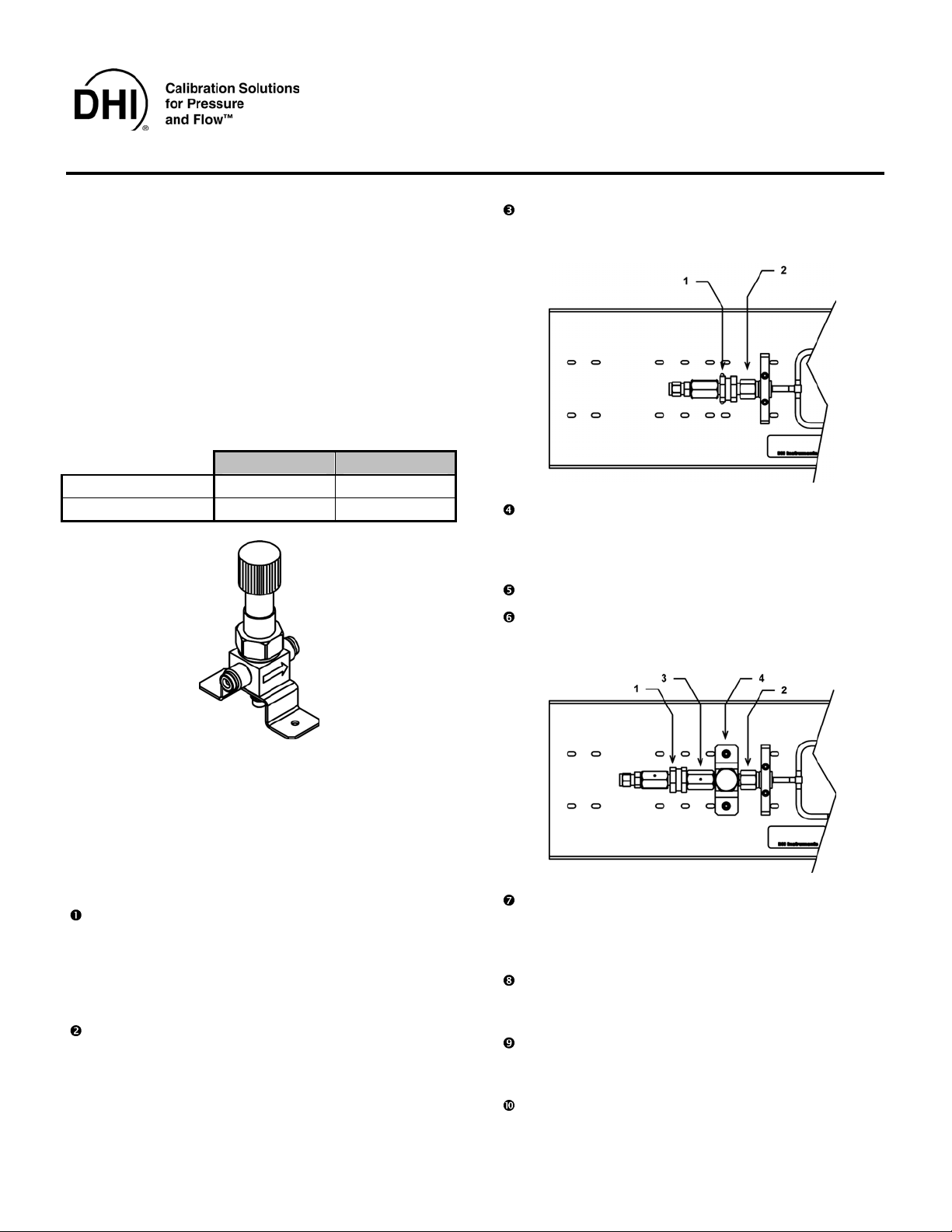
Using a pair of properly sized wrenches, break the
connection between the downstream end of the
filter element (1) and the female VCR
®
swivel nut (2)
on the inlet of the molstic-S. Do not disassemble
the parts on the inlet side of the filter element (1).
Discard the VCR gasket, which is for one-time use.
Thread the included double female VCR union
(non-swivel type), (3), onto the inlet fitting of the
metering valve. Leave it approximately one full
revolution from the fully stopped position.
Place a new 1/4 in. VCR gasket (P/N 102183)
securely against the sealing surface inside the
double female VCR union (non-swivel type) (3).
Install the filter (1) and upstream plumbing into the
female VCR union (3). Tighten the female nut
finger-tight.
Hold male body stationary with a backup wrench.
Tighten the female nut 1/8 turn past finger-tight.
Page 2

Place the flat side of the 60 mm nut plate under
the molstic-S platform (see figure below). Align it
with the holes in the platform and the valve bracket.
Hold it in place.
Thread the socket head cap screws through the
valve bracket and tighten securely into the nut plate.
Do not adjust the supply pressure to the 1/4 in.
metering valve in excess of the maximum operating
pressure of the molbox: 600 kPaa (87 psia) for
molbox1-A700K; 250 kPaa (36 psia) for molbox1A350K.
INSTALLATION OF 1/4 IN. METERING
VALVE ONTO MOLSTIC-S PLATFORMS
WITH REGULATORS
Use double female swivel union (5) in place of the
non-swivel union (3) when installing the metering
valve kit (4) onto a molstic-S that has the
integrated regulator. Use a new 1/4 in. VCR
gasket (P/N 102183) on each end of the union.
Re-secure the regulator (6) to the molstic-S
platform (7) with the socket head cap screws and
nut plate.
MOLSTIC-S OPERATION WITH 1/4 IN.
LOW-FLOW AND MID-FLOW METERING
VALVE
The flow shut-off/metering valve that is integral to the
molstic-S should be opened fully when using the 1/4 in.
low-flow and 1/4 in. mid-flow metering valves to adjust
flow to the molbloc-S. The metering valves supplied
with this kit may limit the maximum obtainable flow rate
of some of the molbloc-S elements that can be mounted
on the 1/4 in. molstic-S (see Table 1). In these cases the
shut-off/metering valve that is integral to the molstic-S
should be used, (and the metering valve removed).
In order to make extremely fine flow rate adjustments
the metering valve can be used in combination with
small adjustments in the supply pressure.
Do not attempt to completely close off flow
using the 1/4 in. low-flow or mid-flow metering
valve. They are not designed to be used as shut
off valves. Damage to the valve seat can occur.
PARTS INCLUDED WITH 1/4 IN.
LOW-FLOW AND MID-FLOW METERING
VALVE KITS
The following parts are included in the shipment:
P/N 401885
Low-Flow Metering Valve Kit
DESCRIPTION QTY PART NO.
Metering valve, low flow 1 102570
Bracket, valve 1 123612
Union, 4VCR F x 4VCR F 1 102181
Gasket, 4VCR 2 102183
Nut plate, 60 mm 1 123621
Washer, flat, M4 2 100918-Z
Screw, SHC, M4 X 12 2 101016-Z
Washer, split lock, #10 2 103021-Z
Screw, SHC, 10-32 X 3/8 2 103277-Z
Washer, flat, #10 2 103278-Z
Union, swivel, 4VCR F x 4VCR F 1 102144
P/N 401666
Mid-Flow Metering Valve Kit
DESCRIPTION QTY PART NO.
Metering valve, mid flow 1 102571
Bracket, valve 1 123612
Union, 4VCR F x 4VCR F 1 102181
Gasket, 4VCR 2 102183
Nut plate, 60 mm 1 123621
Washer, flat, M4 2 100918-Z
Screw, SHC, M4 X 12 2 101016-Z
Washer, split lock, #10 2 103021-Z
Screw, SHC, 10-32 X 3/8 2 103277-Z
Washer, flat, #10 2 103278-Z
Union, swivel, 4VCR F x 4VCR F 1 102144
molbloc, molbloc-S, molbox, molstic and molstic-s are trademarks, registered and otherwise, of DH Instruments, Inc.
Document 560055a 030108
DH Instruments, Inc.
4765 East Beautiful Lane
Phoenix AZ 85044-5318
USA
VCR is a registered trademark of the Swagelok Company.
Viton is a registered trademarks of DuPont deNemours Company.
Tel 602.431.9100
Fax 602.431.9559
dhi@dhinstruments.com
www.dhinstruments.com
 Loading...