

Page 1

FPG8601™/VLPC™
Operation and Maintenance Manual
© 2007 DH Instruments, a Fluke Company
Page 2

FPG8601™/VLPC™ OPERATION AND MAINTENANCE MANUAL
High pressure liquids and gases are potentially hazardous. Energy stored in these liquids and gases
can be released unexpectedly and with extreme force. High pressure systems should be assembled and
operated only by personnel who have been instructed in proper safety practices.
© 2007 DH Instruments, a Fluke Company All rights reserved.
Information in this document is subject to change without notice. No part of this document may be reproduced or transmitted in any
form or by any means, electronic or mechanical, for any purpose, without the express written permission of DH Instruments, a
Fluke Company 4765 East Beautiful Lane Phoenix Arizona 85044-5318 USA.
DH Instruments makes sincere efforts to ensure the accuracy and quality of its’ published materials; however, no warranty,
expressed or implied, is provided. DH Instruments disclaims any responsibility or liability for any direct or indirect damages
resulting from the use of the information in this manual or products described in it. Mention of any product or brand does not
constitute an endorsement by DH Instruments of that product or brand. This manual was originally composed in English and was
subsequently translated into other languages. The fidelity of the translation cannot be guaranteed. In case of conflict between the
English version and other language versions, the English version predominates.
DH Instruments, DH, DHI, PG7000 and CalTool are trademarks, registered and otherwise, of DH Instruments, a Fluke Company.
Swagelok is a registered trademark of the Swagelok Company
Krytox is a trademark of the Dupont de Nemours Company
Document No. 550122e
060105
Printed in the USA
© 2007 DH Instruments, a Fluke Company
Page 3

TABLES AND FIGURES
T
AABBLLEE OOFF
T
C
OONNTTEENNTTS
C
S
TABLE OF CONTENTS .............................................................III
TABLES................................................................................VII
FIGURES..............................................................................VIII
ABOUT THIS MANUAL.............................................................XI
1. INTRODUCTION
1.1 OVERVIEW..............................................................................................................................................1
1.2 REQUIREMENTS.....................................................................................................................................2
1.3 SPECIFICATIONS....................................................................................................................................2
1.3.1 GENERAL SPECIFICATIONS.......................................................................................................................2
1.3.1.1 FPG8601 GENERAL SPECIFICATIONS...................................................................................................2
1.3.1.2 AMBIENT AND INSTRUMENT CONDITION MEASUREMENTS..............................................................3
1.3.1.3 PISTON-CYLINDER...................................................................................................................................3
1.3.1.4 PRESSURE MEASUREMENT...................................................................................................................3
1.3.2 VLPC GENERAL SPECIFICATIONS............................................................................................................4
1.4 FPG PLATFORM FRONT AND REAR PANELS AND VLPC FRONT AND REAR PANELS.................5
1.4.1 TERMINAL FRONT AND REAR PANELS....................................................................................................5
1.4.1.1 FPG TERMINAL FRONT PANEL...............................................................................................................5
1.4.1.2 FPG TERMINAL REAR PANEL .................................................................................................................6
1.4.2 FPG PLATFORM FRONT VIEW ...................................................................................................................7
1.4.3 FPG PLATFORM BACK VIEW .....................................................................................................................8
1.4.3.1 VLPC REAR PANEL ASSEMBLY..............................................................................................................9
................................................................. 1
2. FPG THEORY OF OPERATION ........................................... 11
2.1 OVERVIEW............................................................................................................................................ 11
2.2 PISTON-CYLINDER...............................................................................................................................11
2.3 LOAD CELL...........................................................................................................................................13
2.4 LUBRICATION PRESSURE..................................................................................................................14
2.5 VACUUM REFERENCE PRESSURE....................................................................................................14
2.6 SIMPLIFIED FORMULA FOR CALCULATING DIFFERENTIAL PRESSURE......................................15
2.6.1 REFERENCE LEVEL...................................................................................................................................16
2.7 CORRECTIONS.....................................................................................................................................16
2.7.1 δN1...............................................................................................................................................................16
2.7.2 δN2...............................................................................................................................................................16
2.7.3 δN3...............................................................................................................................................................17
2.8 COMPLETE DIFFERENTIAL PRESSURE EQUATION ........................................................................ 18
3. VLPC THEORY OF OPERATION.......................................... 19
3.1 OVERVIEW............................................................................................................................................ 19
3.2 SUPPLY AND REGULATION................................................................................................................20
3.3 FLOW CONTROL..................................................................................................................................20
3.4 RANGE RESTRICTIONS.......................................................................................................................21
3.5 CONTROL..............................................................................................................................................21
3.6 READY/NOT READY.............................................................................................................................22
Page III © 2007 DH Instruments, a Fluke Company
Page 4

FPG8601™/VLPC™ OPERATION AND MAINTENANCE MANUAL
4. GETTING STARTED .......................................................... 23
4.1 OVERVIEW............................................................................................................................................ 23
4.2 INSTALLING FPG TOOLS ....................................................................................................................23
4.3 SETTING UP FPG TOOLS ....................................................................................................................24
4.4 BASIC FPG HARDWARE SETUP.........................................................................................................25
4.5 SETTING UP THE PISTON-CYLINDER................................................................................................26
4.6 CONNECTING THE FPG MANIFOLD AND VALVES...........................................................................26
4.7 SETTING UP THE FPG FOR OPERATION...........................................................................................28
4.8 SETTING UP THE VLPC .......................................................................................................................29
4.9 INTRODUCING GAS TO THE FPG.......................................................................................................29
4.10 CONNECTING A DUT............................................................................................................................30
4.10.1 GAUGE MODE.............................................................................................................................................30
4.10.2 ABSOLUTE MODE......................................................................................................................................30
4.10.3 ABSOLUTE DIFFERENTIAL MODE...........................................................................................................31
4.11 CONNECTING THE DUT MANIFOLD...................................................................................................32
4.11.1 SETTING UP THE TURBO PUMP ..............................................................................................................33
4.11.2 CONNECTING THE ION GAUGE ...............................................................................................................33
4.12 CHANGING LUBRICATION GAS..........................................................................................................34
4.12.1 PURGING THE LUBRICATING VOLUME WITH A NEW GAS ................................................34
4.12.2 PURGING THE TEST PORT.......................................................................................................................35
5. SYSTEM OPERATION........................................................ 37
5.1 OVERVIEW............................................................................................................................................ 37
5.2 ZEROING THE FPG...............................................................................................................................37
5.2.1 ZERO CONDITION ......................................................................................................................................37
5.2.2 STABILITY TEST.........................................................................................................................................38
5.2.3 STORE ZERO DATA...................................................................................................................................38
5.3 INTERNAL CALIBRATION....................................................................................................................38
5.3.1 DETERMINING CALIBRATION MASS VALUE..........................................................................................38
5.3.2 ACTIVATING NEW CALIBRATION ............................................................................................................39
5.4 SETTING A MEASUREMENT MODE....................................................................................................41
5.5 USING A DUT WITH FPG TOOLS.........................................................................................................41
5.6 ZEROING THE DUT MANIFOLD...........................................................................................................42
5.7 CHANGING PRESSURE WITH THE VLPC...........................................................................................42
5.7.1 SETTING 0 PRESSURE..............................................................................................................................43
5.8 LOGGING DATA WITH THE FPG.........................................................................................................43
5.9 SHUTTING DOWN THE FPG ................................................................................................................44
6. FPG TOOLS ..................................................................... 45
6.1 OVERVIEW............................................................................................................................................ 45
6.2 MAIN MENU...........................................................................................................................................46
6.3 MAIN DISPLAY ......................................................................................................................................46
6.3.1 STATUS BAR ..............................................................................................................................................47
6.3.2 RUN DISPLAY.............................................................................................................................................47
6.3.3 TARE DISPLAY...........................................................................................................................................49
6.3.4 PLOT DISPLAY ...........................................................................................................................................50
6.3.4.1 CUSTOM PLOTS .....................................................................................................................................50
6.3.4.2 STRIP CHARTS .......................................................................................................................................51
6.3.5 LOGGED DATA...........................................................................................................................................52
6.3.6 VLPC CONTROL.........................................................................................................................................54
6.3.7 RUN DIAGNOSTICS....................................................................................................................................56
6.3.8 DUT MANIFOLD..........................................................................................................................................59
6.4 TOOLBARS ...........................................................................................................................................60
6.4.1 WINDOW DISPLAY TOOLBAR ..................................................................................................................60
6.4.2 FUNCTIONS TOOLBAR..............................................................................................................................61
6.4.3 VALVE CONTROL.......................................................................................................................................64
© 2007 DH Instruments, a Fluke Company Page IV
Page 5

TABLES AND FIGURES
6.5 [RUN] .....................................................................................................................................................65
6.5.1 RUN MODE INITIALIZATION......................................................................................................................65
6.5.2 [RUN MONITOR] .........................................................................................................................................66
6.5.3 [RUN W/POINT LOG]..................................................................................................................................66
6.5.4 [RUN TEST SEQUENCE]............................................................................................................................66
6.6 [CONFIG]...............................................................................................................................................68
6.6.1 [SETTINGS].................................................................................................................................................68
6.6.2 [SYSTEM SETUP] .......................................................................................................................................69
6.6.2.1 <SETUP> .................................................................................................................................................69
6.6.2.2 <OPTIONS> .............................................................................................................................................70
6.6.2.3 <DATA FILE> ...........................................................................................................................................72
6.6.3 [FPG CALIBRATION SETUP].....................................................................................................................73
6.6.4 [INTERNAL LIMITS]....................................................................................................................................75
6.6.4.1 <SETUP> .................................................................................................................................................75
6.6.4.2 <PRESSURE> .........................................................................................................................................76
6.6.4.3 <TEMPERATURE> ..................................................................................................................................77
6.6.4.4 <HUMIDITY>............................................................................................................................................78
6.6.4.5 <MASS> ...................................................................................................................................................79
6.6.4.6 <PURGE> ................................................................................................................................................80
6.6.4.7 <VLPC>.................................................................................................................................................... 81
6.6.5 [DUT SELECTION]......................................................................................................................................83
6.7 TEST SEQUENCE EDITOR...................................................................................................................84
6.7.1 TOOLBAR....................................................................................................................................................84
6.7.2 <POINTS> TABLE.......................................................................................................................................85
6.7.3 [POINTS] TAB .............................................................................................................................................87
6.7.4 <SEQUENCE> TAB.....................................................................................................................................88
6.7.5 <CONTROL> TAB.......................................................................................................................................89
6.7.6 <CYCLE> TAB.............................................................................................................................................90
6.8 DUT DEFINITION EDITOR ....................................................................................................................91
6.8.1 TOOLBAR....................................................................................................................................................91
6.8.2 DUT DEFINITION SELECTOR....................................................................................................................92
6.8.2.1 [HEADER] TAB ........................................................................................................................................93
6.8.2.2 [CORRECTION] TAB ...............................................................................................................................94
6.8.2.3 [RANGE] TAB...........................................................................................................................................95
6.8.2.4 [TOLERANCE] TAB .................................................................................................................................96
6.8.2.5 [READ] TAB .............................................................................................................................................97
6.8.2.6 REMOTE COMMAND EDITOR ...............................................................................................................99
6.9 [UNITS] ................................................................................................................................................102
6.9.1 [USER DEFINED UNITS] ..........................................................................................................................102
6.9.2 [ABSOLUTE MODE], [GAUGE MODE]....................................................................................................103
6.9.2.1 [GAUGE MODE].....................................................................................................................................103
6.9.2.2 [ABSOLUTE MODE] ..............................................................................................................................104
6.10 [CHANGE USER LEVEL]....................................................................................................................104
6.11 [TOOLS]...............................................................................................................................................105
6.11.1 [REMOTE COMMUNICATIONS]...............................................................................................................105
6.12 INTERNATIONAL ISSUES ..................................................................................................................105
7. PISTON-CYLINDER MAINTENANCE ...................................107
7.1 OVERVIEW..........................................................................................................................................107
7.2 REMOVING THE PISTON-CYLINDER FROM THE MOUNTING POST .............................................109
7.3 REMOVING THE PISTON FROM THE CYLINDER.............................................................................111
7.4 CLEANING THE PISTON AND CYLINDER ........................................................................................112
7.5 PUTTING THE PISTON INTO THE CYLINDER...................................................................................113
7.6 INS T A L L IN G T H E P I S TO N - C Y L I ND E R I N T HE M O U N TI N G P O S T ............................................114
7.7 RESTORING PISTON-CYLINDER LUBRICATION AND MOBILITY..................................................115
7.7.1 OVERVIEW................................................................................................................................................115
7.7.2 PISTON CENTERING AND LUBRICATING METHODS ..........................................................................115
7.8 DETERMINING EFFECTIVE AREA..................................................................................................... 117
7.8.1 SETTING UP THE SYSTEM......................................................................................................................117
7.8.2 GENERATING A PRESSURE...................................................................................................................118
7.8.3 ADJUSTING THE NEEDLE VALVE..........................................................................................................118
7.8.4 TAKING DATA (FOR EACH PRESSURE)................................................................................................119
7.8.5 CALCULATING THE EFFECTIVE AREA .................................................................................................119
Page V © 2007 DH Instruments, a Fluke Company
Page 6

FPG8601™/VLPC™ OPERATION AND MAINTENANCE MANUAL
8. GENERAL MAINTENANCE ................................................121
8.1 OVERVIEW..........................................................................................................................................121
8.2 REFILLING THE BUBBLER ON THE FPG.........................................................................................121
8.3 ZEROING THE VACUUM SENSOR....................................................................................................122
8.3.1 SET – UP....................................................................................................................................................123
8.3.2 WARM-UP..................................................................................................................................................123
8.3.3 TEST THE ZERO OF THE VACUUM SENSOR........................................................................................123
8.4 CALIBRATING THE INTERNAL CALIBRATION MASS.....................................................................125
8.4.1 INITIAL PREPARATIONS .........................................................................................................................125
8.4.2 REMOVE THE LOAD CELL COVER ........................................................................................................125
8.4.3 REMOVE THE CALIBRATION MASS AND DRIVE..................................................................................126
8.4.4 DETERMINE THE TRUE MASS VALUE OF THE INTERNAL CALIBRATION MASS............................126
8.4.5 PUT THE MASS BACK INTO THE DRIVE ASSEMBLY ..........................................................................127
8.4.6 REATTACH THE LOAD CELL COVER....................................................................................................127
8.4.7 FINAL STEPS............................................................................................................................................127
8.5 MOUNTING POST PRT CALIBRATION..............................................................................................128
8.5.1 REMOVE THE PRTS.................................................................................................................................128
8.5.2 CREATE THE PRT CABLE ADAPTER ....................................................................................................128
8.5.3 DETERMINE THE RO VALUE ..................................................................................................................129
8.5.4 ENTER THE RO VALUE INTO THE FPG TERMINAL..............................................................................129
8.5.5 REATTACH THE PRTS TO THE FPG ......................................................................................................130
8.6 PREPARING FOR STORAGE / SHIPMENT........................................................................................130
8.6.1 FPG8601....................................................................................................................................................130
8.6.2 VLPC..........................................................................................................................................................130
8.6.3 3-DUT MANIFOLD.....................................................................................................................................131
9. DATA FILES ...................................................................133
9.1 OVERVIEW..........................................................................................................................................133
9.2 POINT LOG DATA FILE (*.DAT).........................................................................................................133
9.2.1 NAMING AND STORING DATA FILES ....................................................................................................133
9.2.2 FILE FORMAT ...........................................................................................................................................133
9.3 INTERNAL CALIBRATION LOG FILE................................................................................................133
9.4 SYSTEM ZERO LOG FILE ..................................................................................................................134
9.5 ERROR LOG FILE...............................................................................................................................134
10. TROUBLESHOOTING .......................................................135
10.1 OVERVIEW ..........................................................................................................................................135
11. APPENDIX ......................................................................137
11.1 INTERNAL VALVES............................................................................................................................137
11.2 UNIT CONVERSIONS..........................................................................................................................139
11.3 FPG8601 PRESSURE CALCULATIONS ............................................................................................140
11.3.1 COMPENSATED PRESSURES ................................................................................................................140
11.3.2 DIFFERENTIAL PRESSURES ..................................................................................................................140
11.3.3 CORRECTI ON TE RMS..............................................................................................................................140
11.3.4 THERMAL TRANSPIRATION CORRECTION..........................................................................................141
11.3.5 SAMPLE CALCULATIONS.......................................................................................................................144
11.3.5.1 GAUGE PRESSURE..............................................................................................................................144
11.3.5.2 ABSOLUTE PRESSURE .......................................................................................................................145
11.3.5.3 ABSOLUTE DIFFERENTIAL PRESSURE.............................................................................................146
11.3.5.4 INTERNAL CALIBRATION (KCAL)........................................................................................................147
11.4 DECLARATION OF CONFORMITY..................................................................................................... 147
11.5 GROUNDING / ELECTRICAL SCHEMATICS.....................................................................................147
11.5.1 SYSTEM LEVEL GROUNDING.................................................................................................................148
11.5.2 FPG GROUN D DIAGRAM.........................................................................................................................149
11.5.3 VLPC POWER DIAGRAM.........................................................................................................................150
12. WARRANTY STATEMENT .................................................151
13. GLOSSARY
© 2007 DH Instruments, a Fluke Company Page VI
.....................................................................153
Page 7

TABLES AND FIGURES
T
AABBLLEES
T
Table 1. Nominal VLPC
Table 2. Nominal VLPC Ranges, 15 kPa Unit ........................................................................................... 21
Table 3. Equipment for Basic FPG Hardware Setup ................................................................................ 25
Table 4. Internal Calibration Results Options ............................................................................................40
Table 5. <Run Display> Labels.................................................................................................................. 48
Table 6. <Tare Display> Labels ................................................................................................................. 49
Table 7. <Custom Plot Properties> Tab Fields .......................................................................................... 51
Table 8. <Logged Points> Labels .............................................................................................................. 53
Table 9. <VLPC Interface> Options ........................................................................................................... 55
Table 10. <Diagnostics Display> Options.................................................................................................. 56
Table 11. <DUT Manifold> Color Scheme ................................................................................................. 59
Table 12. <DUT Manifold> Display ............................................................................................................ 60
Table 13. Window Display Toolbar Options............................................................................................... 61
Table 14. Functions Toolbar Option........................................................................................................... 61
Table 15. System Settings ......................................................................................................................... 68
Table 16. <System Setup><Setup> Options .............................................................................................69
Table 17. <System Setup><Options> Options .......................................................................................... 71
Table 18. <Options>, <Data File> Tab Fields............................................................................................ 72
Table 19. <FPG8601 Calibration Setup> Options ..................................................................................... 74
Table 20. <Internal Limits> <Setup> Options ............................................................................................75
Table 21. <Internal Limits> <Pressure> Options .......................................................................................77
Table 22. <Internal Limits> <Temperature> Options ................................................................................. 78
Table 23. <Internal Limits> <Humidity> Options........................................................................................ 79
Table 24. <Internal Limits> <Mass> Options ............................................................................................. 80
Table 25. <Internal Limits> <Purge> Options ............................................................................................ 81
Table 26. <Internal Limits> <VLPC> Options ............................................................................................ 82
Table 27. <DUT Selection & I/O Setup> Options....................................................................................... 83
Table 28. Test Sequence Editor, <Toolbar> Options ................................................................................ 84
Table 29. Test Sequence Editor, <Points> Options................................................................................... 86
Table 30. Test Sequence Editor, <Points> Tab Fields .............................................................................. 87
Table 31. Test Sequence Editor, <Sequence> Tab Fields ........................................................................ 88
Table 32. Test Sequence Editor, <Control> Tab Fields............................................................................. 89
Table 33. Test Sequence Editor, <Cycle> Tab Fields ............................................................................... 90
Table 34. DUT Definition Editor, <Toolbar> Features ............................................................................... 91
Table 35. DUT Definition Editor, [Header] Tab Fields ............................................................................... 93
Table 36. DUT Definition Editor, [Correction] Tab Fields........................................................................... 94
Table 37. DUT Definition Editor, [Range] Tab Fields................................................................................. 95
Table 38. DUT Definition Editor, [Tolerance] Tab Fields ........................................................................... 97
Table 39. DUT Definition Editor, [Read] Tab Fields................................................................................... 98
Table 40. Piston-Cylinder Maintenance Equipment................................................................................. 107
Table 41. Effective Area Calculation Variables........................................................................................ 119
Table 42. Sample Effective Area Spread Sheet ...................................................................................... 120
Table 43. Bubbler Maintenance Equipment............................................................................................. 121
Table 44. Vacuum Reference Zeroing Equipment List ............................................................................ 122
Table 45. Vacuum Reference Zeroing Equipment List ............................................................................ 125
Table 46. Effective Area Calculation Variables........................................................................................ 127
Table 47. PRT Calibration Cable Connections ........................................................................................ 128
Table 48. Effective Area Calculation Variables........................................................................................ 129
S
Ranges ................................................................................................................ 19
Page VII © 2007 DH Instruments, a Fluke Company
Page 8

FPG8601™/VLPC™ OPERATION AND MAINTENANCE MANUAL
Table 49. Troubleshooting Tips ............................................................................................................... 135
Table 50. Internal Valve Descriptions ...................................................................................................... 138
Table 51. Unit Conversion Factors .......................................................................................................... 139
Table 52. FPG Defined Pressure Calculation Variables.......................................................................... 142
Table 53. DHI Authorized Service Providers ...........................................................................................151
F
IIGGUURREES
F
Figure 1. FPG8601 Terminal Front Panel.................................................................................................... 5
Figure 2. FPG8601 Terminal Rear Panel
Figure 3. FPG Platform Front View
Figure 4. FPG Platform Back
Figure 5. VLPC Rear Panel.......................................................................................................................... 9
Figure 6. Piston-cylinder Lubric
Figure 7. Internal Calibrat
Figure 8. FPG Forc
Figure 9. Gauge Mode VLPC Block Diagram
Figure 10. Absolute Mode VLPC Bloc
Figure 11. VLPC Ready Criterion
Figure 12. FPG8601 Syst
Figure 13. FPG8601 Mani
Figure 14. Internal Calibration Res
Figure 15. FPG Tools
Figure 16. <Status
Figure 17. <Run Display>
Figure 18. <Tare Display
Figure 19. <Plot Data>
Figure 20. <Custom Plot Properties>
Figure 21. <Logged Point
Figure 22. <VLPC Interfac
Figure 23. <Select VLPC
Figure 24. <Diagnos
Figure 25. Window Dis
Figure 26. Window Dis
Figure 27. Manual Valve Control Tool
Figure 28. <Settings
Figure 29. <System Setup><
Figure 30. <System Setup><
Figure 31. <System Setup>
Figure 32. <FPG8601 Calibration Setup>
Figure 33. <Internal Limits>
Figure 34. <Internal Limits>
Figure 35. <Internal Limits>
Figure 36. <Internal Limits>
Figure 37. <Internal Limits>
Figure 38. <Internal Limits>
Figure 39. <Internal Limits>
Figure 40. <DUT Selec
Figure 41. Test Sequence Editor, <Tool
Figure 42. Test Sequence Editor, <Test Points> Tabl
Figure 43. Test Sequence Editor, <Points> Tab
Figure 44. Test Definition Editor, <
S
.................................................................................................... 6
.............................................................................................................. 7
View .............................................................................................................. 8
ating Flow ................................................................................................. 12
ion Mass Alignment........................................................................................... 13
es................................................................................................................................. 17
............................................................................................ 20
k Diagram....................................................................................... 20
.............................................................................................................. 22
em Schematic.................................................................................................... 23
fold Connection................................................................................................. 27
ults Window......................................................................................... 39
(Factory Mode) ....................................................................................................... 46
Bar> ............................................................................................................................. 47
.......................................................................................................................... 47
>.......................................................................................................................... 49
............................................................................................................................... 50
......................................................................................................... 51
s> Display.......................................................................................................... 52
e> ..................................................................................................................... 55
Range>.............................................................................................................. 55
tics Display> .............................................................................................................. 56
play Toolbar ........................................................................................................... 59
play Toolbar ........................................................................................................... 60
bar .................................................................................................. 65
>................................................................................................................................. 68
Setup> Tab .................................................................................................. 69
Interface> ..................................................................................................... 71
, <Data File> Tab ...........................................................................................72
.................................................................................................. 74
<Setup>......................................................................................................... 75
<Pressure>.................................................................................................... 76
<Temperature> .............................................................................................78
<Humidity> .................................................................................................... 79
<Mass> ......................................................................................................... 80
<Purge> ........................................................................................................ 81
<VLPC>......................................................................................................... 82
tion & I/O Setup>................................................................................................... 83
bar>............................................................................................. 84
e............................................................................. 85
........................................................................................ 87
Control> Tab ....................................................................................... 89
© 2007 DH Instruments, a Fluke Company Page VIII
Page 9

TABLES AND FIGURES
Figure 45. Test Definition Editor, <Cycle> Tab .......................................................................................... 90
Figure 46. DUT Definition Editor, <
Figure 47. <DUT Selec
tion> Tool .............................................................................................................. 93
Figure 48. DUT Definition Editor, [Header Tab
Figure 49. DUT Definition Editor, [Correc
Figure 50. DUT Definition Editor, [Range] Tab
Figure 51. DUT Definition Editor, [Tolerance] Tab
Figure 52. DUT Definition Editor, [Read]
Figure 53. <Insert Speci
al Character> Panel............................................................................................. 99
Figure 54. <Initialization Commands
Figure 55. <Read Com
mands Editor> Panel........................................................................................... 101
Figure 56. <RS232 Settings> Panel
Figure 57. <User Defined Unit Setup>
Figure 58. <Remote Communications
Figure 59. FPG8601 Piston Assembly in
Figure 60. Removing the Mounting Post
Figure 61. Removing the Pis
Figure 62. Alignment of the FPG pis
Figure 63. FPG8601 and PG7000 Cross
Figure 64. FPG8601 Bubbling System
Figure 65. Calibration Mas
s Drive Assembly ........................................................................................... 126
Figure 66. PRT Calibration Cable Adaptor
Figure 67. FPG Internal V
alve Configuration........................................................................................... 137
Toolbar>.............................................................................................. 91
.......................................................................................... 93
tion] Tab .................................................................................... 94
.......................................................................................... 95
..................................................................................... 96
Tab ............................................................................................ 97
Editor> Panel................................................................................. 100
........................................................................................................ 101
..................................................................................................... 102
> ................................................................................................... 105
Mounting Post......................................................................... 108
.................................................................................................. 110
ton............................................................................................................... 110
ton in the cylinder ........................................................................... 113
Float Setup ............................................................................. 117
.................................................................................................... 122
.............................................................................................. 128
Page IX © 2007 DH Instruments, a Fluke Company
Page 10

FPG8601™/VLPC™ OPERATION AND MAINTENANCE MANUAL
N
N
OOTTEES
S
© 2007 DH Instruments, a Fluke Company Page X
Page 11
ABOUT THIS MANUAL
A
BBOOUUTT
A
This manual provides the user with the information necessary to operate the FPG8601 system. It also
includes a great deal of additional information provided to help you optimize system use and take full
advantage of its many features and functions.
Realize that the numbers on the PC software screen captures and the VLPC range information are for
example purposes only. In some cases the information required to setup the FPG is installed with FPG
Tools. In other cases, the values must be entered into the FPG calibration setup (see Section 6.6.3).
Before u
All first time FPG users should read Section 2 for a comprehensive description of general operating
prin
10 to troubleshoot unexpected system behavior b
Certain words and expressions have specific meaning as they pertain to the FPG System. The Glossary
(see Section 13) is useful as a quick reference for exact definition of specific words and expressions as
they are used
sing the manual, take a moment to familiarize yourself with the Table of Contents structure.
ciples. Section 8 provides maintenance and calibration information. Use the inform
FOR THOSE OF YOU WHO “DON’T READ MANUALS”, GO DIRECTLY TO SECTION 4 TO SET UP YOUR
FPG SYSTEM. THEN GO TO SECTIONS 5 and 6. THIS WILL GET YOU RUNNING QUICKLY WITH
MINIMAL RISK OF CAUSING DAMAGE TO YOURSELF OR YOUR FPG. THEN… WHEN YOU HAVE
QUESTIONS OR START TO WONDER ABOUT ALL THE GREAT FEATURES YOU MIGHT BE MISSING, GET
INTO THE MANUAL!
T
T
in this manual.
HHIISS
M
AANNUUAAL
M
L
ased on the symptoms of that behavior.
ation in Section
Manual Conventions
(CAUTION) is used in throughout the manual to identify user warnings and cautions.
(NOTE) is used throughout the manual to identify operating and applications advice and additional
explanations.
[ ] indicates direct function keys or menu options (e.g., [Run]).
< > indicates FPG Tools screen displays (e.g., <FPG Pressure>).
Page XI © 2007 DH Instruments, a Fluke Company
Page 12

FPG8601™/VLPC™ OPERATION AND MAINTENANCE MANUAL
N
N
OOTTEES
S
© 2007 DH Instruments, a Fluke Company Page XII
Page 13

1. INTRODUCTION
.
11.
I
NNTTRROODDUUCCTTIIOON
I
N
1.1 OVERVIEW
The FPG8601 (Force-Balanced Piston Gauge), VLPC (Very Low Pressure Controller) and FPG Tools
(PC Based Software) are used in conjunction to act as a high precision pressure measurement and data
acquisition system. Operator interaction with the FPG/VLPC and its extensive capabilities is accomplished
through the PC based software from a computer via a standard RS232 port. FPG Tools also provides
features to define a test sequence, read DUT’s with a standard RS232 or IEEE-488 output, and log data
to a data file.
FPG pressure is defined by using a high precision load cell to measure the force exerted on the effective
area of a piston-cylinder (see Section 2). Instead of rotating the piston like othe
provides sensitivity between the piston and cylinder by maintaining a constant flow through the annular
gap. This flow generates a centering force that prevents the piston from touching the cylinder during
normal operation. Noise normally associated with rotation is therefore not present.
FPG platforms are designed to maximize metrological performance and ease of operation in both gauge
and absolute modes. Many features are included to enhance the fundamental precision and stability of
pressure measurements as well as simplifying use and reducing the operator influence on the
measurements.
r piston gauges, the FPG
The VLPC generates low pressure in gauge and absolute modes (0 to 15 kPa). It is used to set and
stabilize pressure as read by the FPG so that the VLPC/FPG combination can be used to set user
specified target pressure values. The general operating principle of the VLPC is to generate a stable flow
through one of a number of restrictions depending on the range of pressure to be controlled (see Section
3.4). The pressure drop across the restriction is the controlled
FPG is used to dynamically readjust the flow to obtain the desired target pressure.
FPG Tools is the complete interface to both the FPG and the VLPC. An interface to all functional aspects
of both instruments is provided by the software. FPG Tools uses three basic modes of operation to
remotely interact with the FPG and VLPC: [Run Mode], [Run w/Point Logging], and [Run Test Sequence]
(see Section 6.5). These modes respectively allow simple monitoring of pressure, monitoring of pressure
with user dep
A DUT can be used in any run mode for real-time error determination and/or data acquisition.
endant steps and data acquisition, and monitoring with defined test steps and data acquisition.
differential pressure. Feedback from the
Page 1 © 2007 DH Instruments, a Fluke Company
Page 14

FPG8601™/VLPC™ OPERATION AND MAINTENANCE MANUAL
1.2 REQUIREMENTS
FPG Tools is a PC based application designed for 32 bit versions of Windows. The PC requirements
stated below are necessary to maintain the minimum acceptable performance between the software and
related hardware components.
• Windows XP, 98, NT service pack 4 or greater
• 500 MHz Pentium Processor or compatible
• 32 Mb of Ram
• 12 Mb free hard drive space
1.3 SPECIFICATIONS
1.3.1 GENERAL SPECIFICATIONS
1.3.1.1 FPG8601 GENERAL SPECIFICATIONS
Power Requirements: 85 to 264 VAC, 50 to 60 Hz, 60 VA consumption
Operating Temperature:
Weight: Instrument platform
FPG Platform 31.2 kg (61 lb)
FPG Terminal 1.4 kg (3 lb)
Dimensions:
FPG Platform 53.4 cm H x 35.8 cm W x 35.5 cm D
FPG Terminal 12 cm H x 15 cm W x 20 cm D
Microprocessors:
Instrument Platform Motorola 68302
FPG Terminal Hitachi 64180
Communication Ports:
RS232
IEEE-488.2 Not used
Maximum Pressure Ranges: 0 – 15 kPa Gauge and Absolute
Operating Media: Gas: air or Nitrogen (N
Pressure Supplies: Lubrication port: 700 - 850 kPa (100 - 120 psi), supply
Drive In Supply: 600 to 1000 kPa (90 to 150 psi) air
Maximum Overpressure Limit: +20 kPa to –10 kPa (+3 to – 1.5 psi)
Pressure Connections:
Lubrication Supply Port
Upper Test Port
Lower Test Port
Drive In Port
Vacuum Port
CE Conformance: Not available
Driver Port (Ext Valve): Not used
15 to 35 °C
(21 in. H x 14.1 in. W x 14 in. D)
(4.7 in. H x 5.9 in. W x 7.9 in. D)
COM1: Host computer
COM2: VLPC
COM3: Not Used
)
2
must remain constant ± 1 % to meet control specifications
1/8 in. NPT
KF16
KF16
1/8 in. NPT
1/8 in. NPT
© 2007 DH Instruments, a Fluke Company Page 2
Page 15

1. INTRODUCTION
1.3.1.2 AMBIENT AND INSTRUMENT CONDITION MEASUREMENTS
Temperature:
Range
Resolution
Accuracy
Relative Humidity:
Range
Resolution
Accuracy
Vacuum:
Range
Resolution
Accuracy
Ambient and Lubrication
Pressure Sensor:
Range
Resolution
Accuracy
Lubrication Pressure
[°C] [°C]
0 to 40 0 to 40
0.1 0.01
± 0.2 ± 0.1
5 to 95 %RH
1 %RH
± 10 %RH
13 Pa
1 mPa
± 20 mPa
200 kPa
1 Pa
± 0.1 kPa
1.3.1.3 PISTON-CYLINDER
Cylinder Material: Tungsten carbide
Piston Material: Tungsten carbide
Nominal Diameter: 35 mm
Nominal Area:
Mounting System: Non-rotative piston
980.5164 mm
Piston-Cylinder
2
1.3.1.4 PRESSURE MEASUREMENT
Resolution1: 10 mPa
Precision Reproducability
Uncertainty
Standard Measurement:
1. Resolution: The smallest variation in input detectable in output.
2. Reproducibility: Combined reproducibility of force measurement and long term stability of
piston-cylinder effective area.
3. Standard Measurement Uncertainty: All sources of uncertainty under typical operating
conditions are identified, quantified and combined following ISO/TAG4/WG3. The result is then
rounded upwards to provide conservative global figures for the typical user in typical conditions
of the maximum deviation from the true value of the pressure determined by the FPG8601 and
the pressure actually present at the test point.
2
:
± 20 mPa
3
:
Absolute: ± (25 mPa + 0.003 % of reading)
Gauge and absolute differential: ± (20 mPa + 0.003 %
of reading)
Page 3 © 2007 DH Instruments, a Fluke Company
Page 16

FPG8601™/VLPC™ OPERATION AND MAINTENANCE MANUAL
1.3.2 VLPC GENERAL SPECIFICATIONS
Power Requirements: 85 to 264 VAC, 47 to 60 Hz, 70 VA max. consumption
Operating Temperature Range: 15 to 35 °C
Storage Temperature Range: - 20 to 70 °C
Weight: 41.6 kg (91.5 lb)
Dimensions: 30.5 cm H x 53.4 cm W x 50.5 cm D
Microprocessor: Motorola 68302, 16 MHz
Communication Ports:
RS232
IEEE-488.2
Control Specifications:
Operating Medium: Gas: air or Nitrogen (N
Pressure Supplies: SUPPLY port: 700 - 850 kPa (100 - 120 psi), supply must remain
Drive Air Supply: 600 to 1000 kPa (90 to 150 psi) air
Pressure Connections: Test (Lo) 1/4 VCO
(12 in. H x 21 in. W x 19.9 in. D)
COM1: FPG
COM2:: Not Used
Not used
± 0.02 Pa + 30 ppm of range selected
constant ± 1 % to meet control specifications
Test (Hi) 1/4 VCO
ATM 1/4 VCO
Vacuum 3/8 VCO
Supply 1/8 NPT F
Drive 1/8 NPT F
)
2
© 2007 DH Instruments, a Fluke Company Page 4
Page 17
1. INTRODUCTION
1.4 FPG PLATFORM FRONT AND REAR PANELS AND VLPC FRONT AND REAR PANELS
1.4.1 TERMINAL FRONT AND REAR PANELS
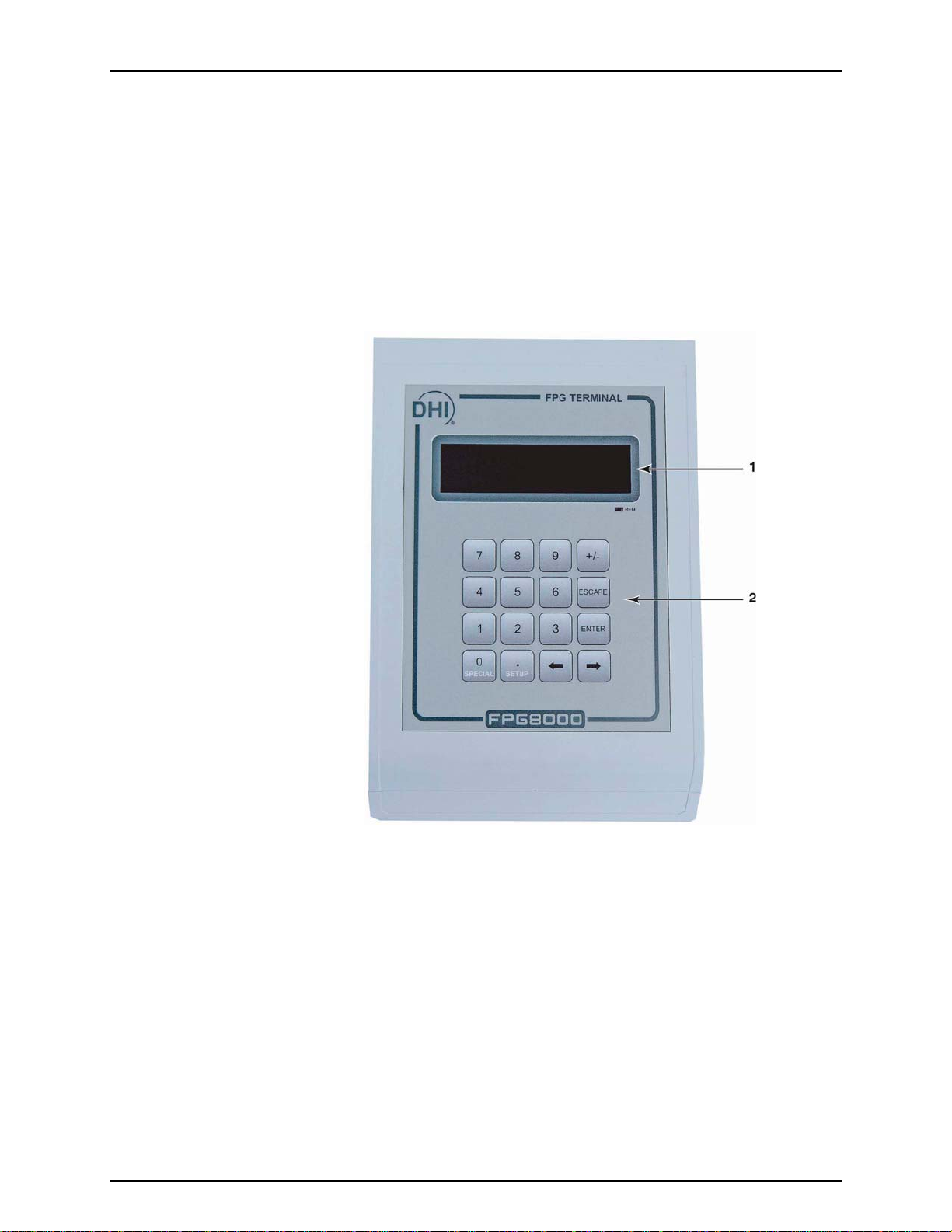
1.4.1.1 FPG TERMINAL FRONT PANEL
The front panel assembly provides a 2 x 20 vacuum fluorescent display and a 4 x 4
membrane keypad for local user interface.
1. Display
2. Multi-Function Keypad
Figure 1. FPG8601 Terminal Front Panel
Page 5 © 2007 DH Instruments, a Fluke Company
Page 18
FPG8601™/VLPC™ OPERATION AND MAINTENANCE MANUAL
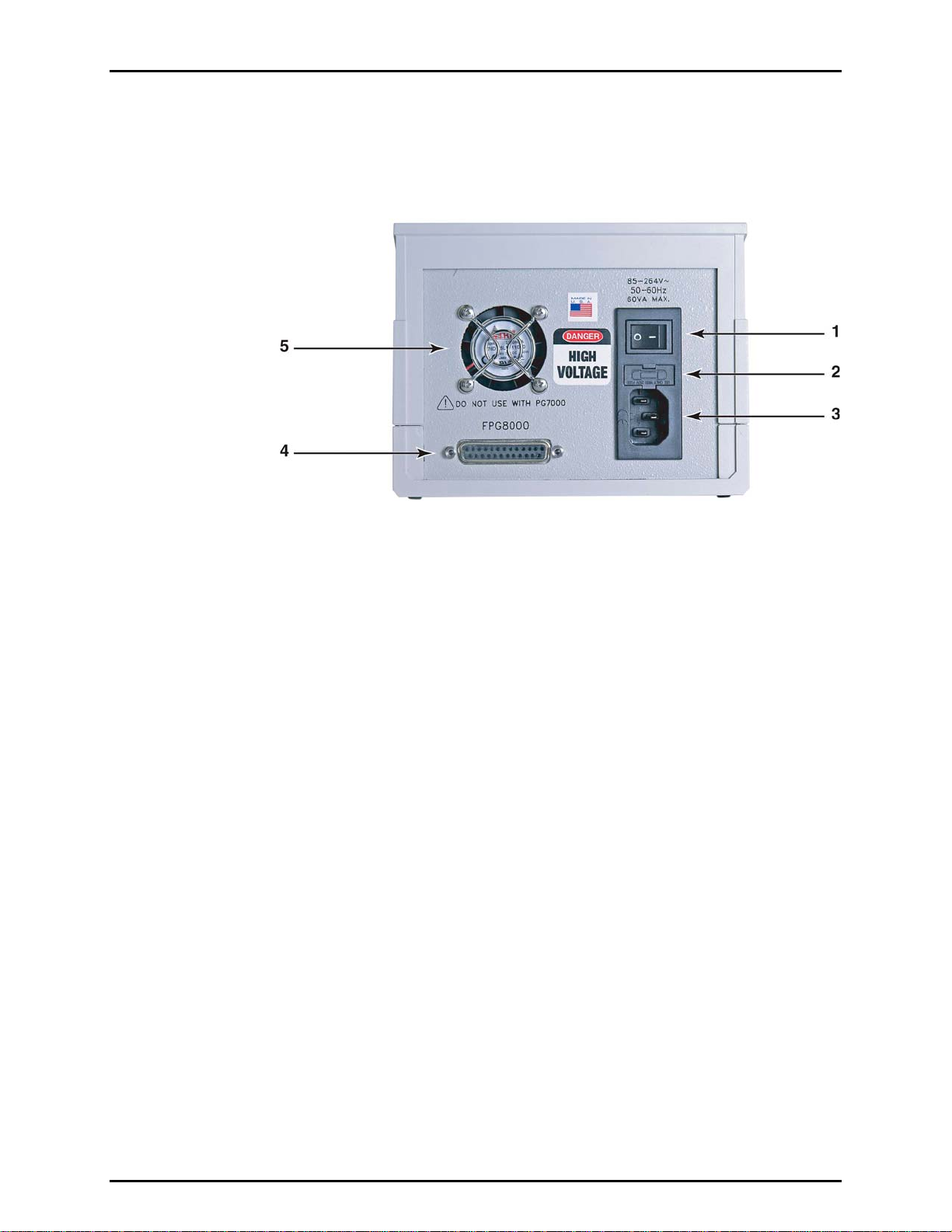
1.4.1.2 FPG TERMINAL REAR PANEL
The rear panel assembly provides the communications connection to the FPG
platform and the power connection module.
1. Power Switch
2. Fuse
3. Power Receptacle
4. Connector for Cable to
FPG (25 pin
5. Cooling Fan
Figure 2. FPG8601 Terminal Rear Panel
© 2007 DH Instruments, a Fluke Company Page 6
Page 19
1. INTRODUCTION
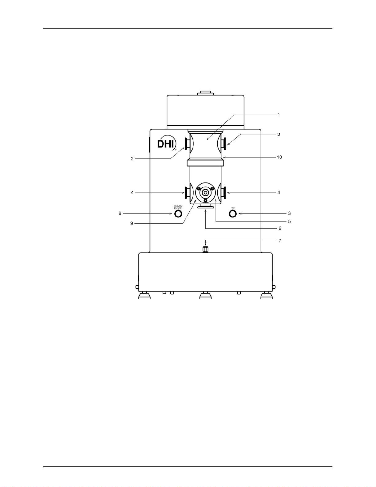
1.4.2 FPG PLATFORM FRONT VIEW
The front of the FPG provides the connections to the VLPC, DUT and vacuum sensor. It also
provides the electrical connection to the mounting post PRTs and vacuum sensor reading.
1. Upper Mounting Post
2. TEST+ (KF-16)
3. Mounting Post PRT Connector
4. TEST- (KF-16)
5. Lower Mounting Post
Figure 3. FPG Platform Front View
Page 7 © 2007 DH Instruments, a Fluke Company
6. Vacuum Reference Port (KF-25)
7. Mounting Post Reference
8. Vacuum Sensor Connector
9. Vacuum Sensor Port
10. Reference Level
Page 20
FPG8601™/VLPC™ OPERATION AND MAINTENANCE MANUAL
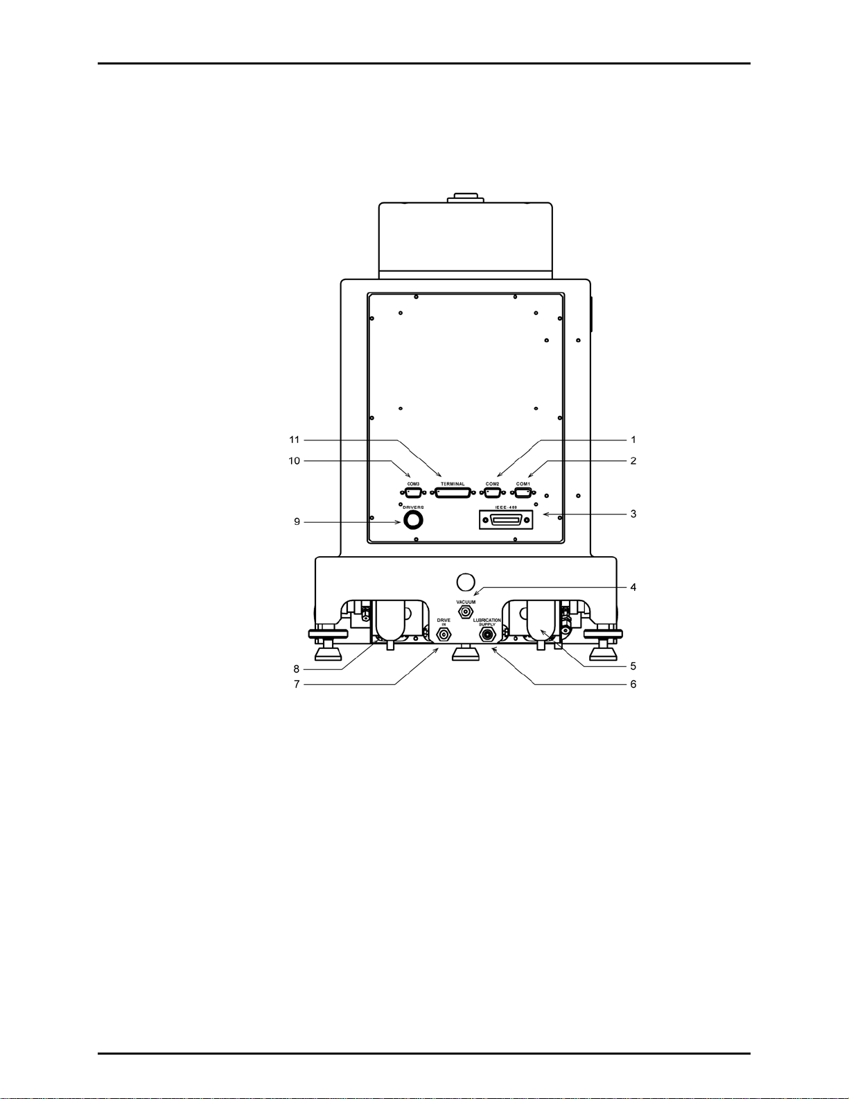
1.4.3 FPG PLATFORM BACK VIEW
The FPG platform rear panels provide the connection to the FPG Terminal, remote
communication connections and supply pressure connection ports.
1. COM2 (RS232) – VLPC
2. COM1 (RS232) – Remote Host
Communication
3. IEEE-488 – Not Used
4. Absolute Mode – Lubrication
Pressure Vacuum
5. Bubbler
Figure 4. FPG Platform Back View
© 2007 DH Instruments, a Fluke Company Page 8
6. Lubrication Supply
7. Drive In
8. Coalescing Filter
9. Drivers Option Connector Not Used
10. COM3 (RS232) – Not Used
11. FPG Terminal Port
Page 21
1. INTRODUCTION
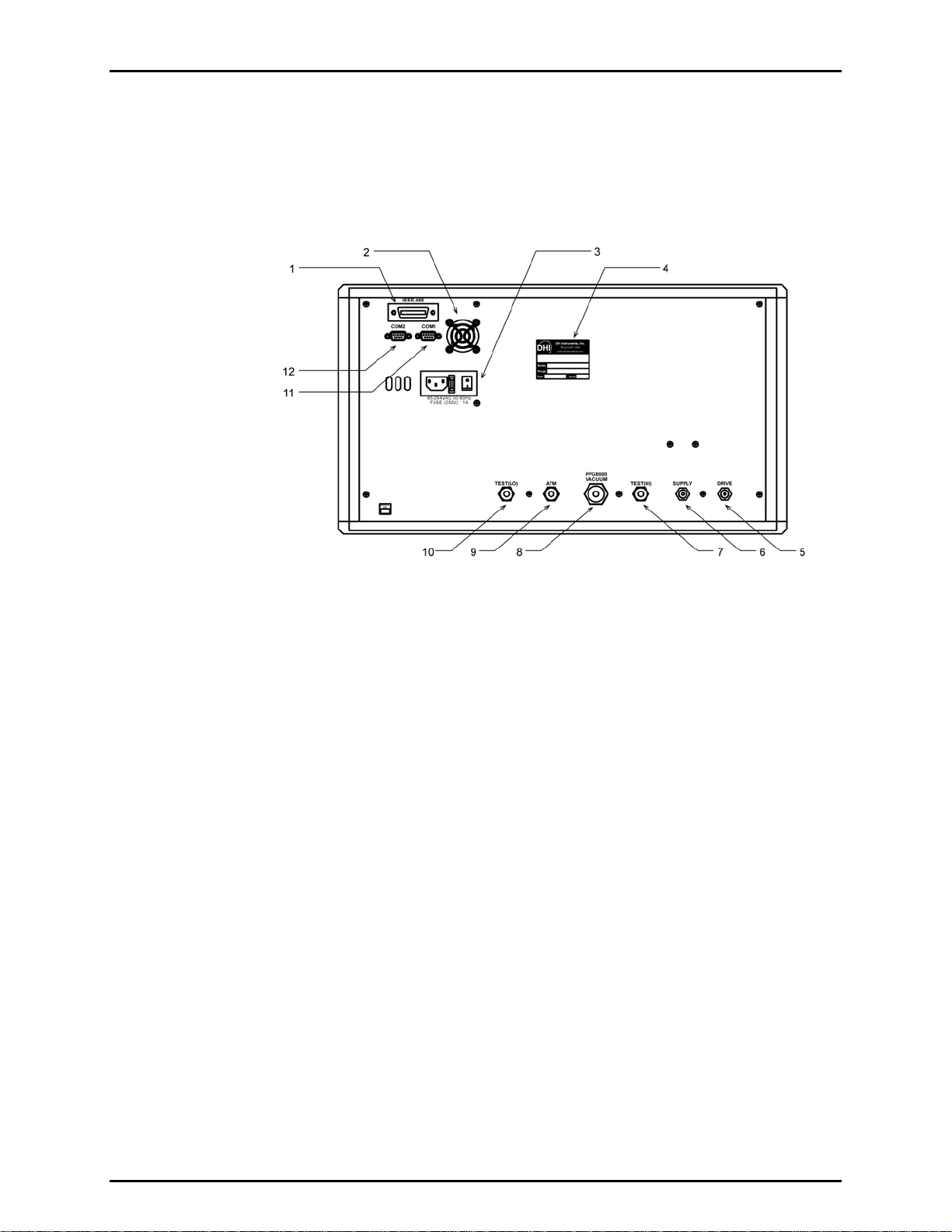
1.4.3.1 VLPC REAR PANEL ASSEM BLY
The rear panel assembly provides pressure connections, communications
interfaces, the power ON/OFF module and product labeling. Pressure fittings are
internally secured to prevent loosening when making and breaking connections.
1. IEEE-488 Connector – Not Available
2. Fan
3. Power Switch
4. Label, Product
5. Pressure Connection – Drive
6. Pressure Connection – Supply
Figure 5. VLPC Rear Panel
7. Pressure Connection – Test (Hi)
8. Pressure Connection – FPG
Vacuum
9. Pass Through – ATM Ref
10. Pressure Connection – Test (Lo)
11. COM1 (RS232) – To FPG
12. COM2 (RS232) – Not Used
Page 9 © 2007 DH Instruments, a Fluke Company
Page 22

FPG8601™/VLPC™ OPERATION AND MAINTENANCE MANUAL
N
N
OOTTEES
S
© 2007 DH Instruments, a Fluke Company Page 10
Page 23

2. FPG THEORY OF OPERATION
.
22.
G
FFPPG
T
HHEEOORRYY OOFF
T
O
PPEERRAATTIIOON
O
N
2.1 OVERVIEW
The FPG measures low gauge and absolute pressure by using a load cell to measure the force on the
effective area of a 35 mm piston. A measurement mode specific lubricating pressure is applied to the
annular gap of the piston-cylinder to provide a centering force on the piston. Compensation for the
effects of the lubrication pressure on the load cell and piston are determined during the
manufacturing process. The output of the load cell combined with the force components associated with
the lubrication pressure determines the total force on the piston. This force divided by the temperature
corrected effective area of the piston determines the differential pressure of the FPG.
In gauge mode, the FPG differential pressure is equivalent to the gauge pressure of the system since the
lower port of the FPG is exposed to atmosphere. In absolute mode, the lower port of the FPG is
connected to vacuum. Because of the lubricating flow, a perfect vacuum can never be achieved;
therefore a high precision low range vacuum reference sensor is used to measure the residual
vacuum pressure. This pressure is applied to the FPG differential pressure to obtain the final system
absolute pressure. Absolute differential operation of the FPG is the same as absolute mode operation
without the use of the vacuum reference sensor.
To support automatic zeroing and calibration of the FPG the mounting post assembly contains several
pneumatic valves that are automatically controlled by FPG Tools. Many internal sensors are also present
to verify that the FPG is operating in the required conditions and to make pressure buoyancy corrections.
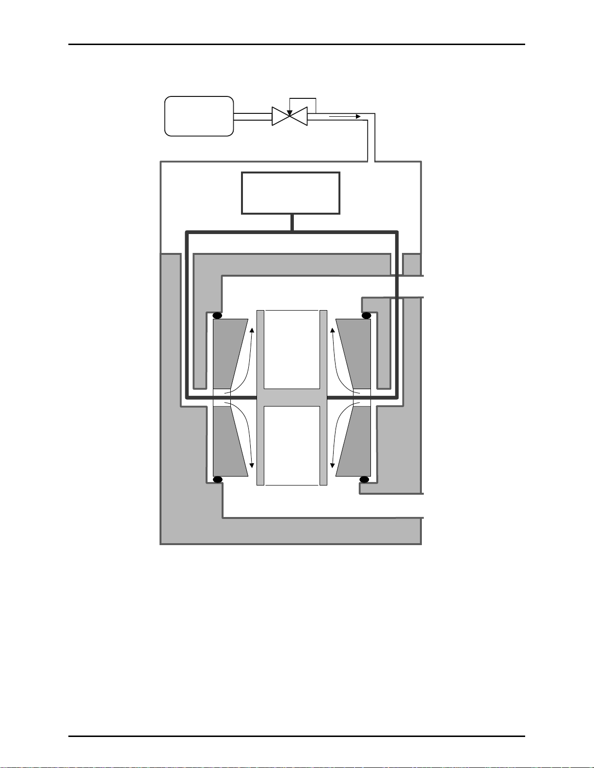
2.2 PISTON-CYLINDER
The FPG uses a 35 mm diameter, tungsten carbide piston-cylinder designed with a pressure to mass
conversion coefficient of 10 kPa/kg. The cylinder has a conical shape on its interior surface to generate a
centering force on the piston when a lubrication pressure is applied in the annular gap through the center
of the cylinder (see Figure 6). The non-rotating piston is conne
freedom mechanical assembly located at its center of gravity. This allows the piston to center itself in the
cylinder under the influence of the lubricating pressure. As a result, the piston is perfectly mobile, making
no contact with the cylinder.
cted to the load cell by a multi degree of
Page 11 © 2007 DH Instruments, a Fluke Company
Page 24
FPG8601™/VLPC™ OPERATION AND MAINTENANCE MANUAL
LUBRICATING
SUPPLY
REG
FLOW
MASS
COMPARATOR
P
hi
P
lub
P
ref
Figure 6. Piston-cylinder Lubricating Flow
The piston-cylinder resides in the mounting post that provides upper and lower measurement chambers
equipped with high pressure (P
) and low pressure (P
hi
) connections at the two extremities of the
ref
piston-cylinder. The high pressure port is the measurement port of the FPG. The low pressure port is
considered the reference port of the system. When the port is exposed to atmosphere, the FPG will read
gauge pressure. If the port is exposed to vacuum, the FPG will measure absolute differential pressure.
The measured value of the low pressure port must be applied to the FPG differential pressure to get an
absolute pressure.
© 2007 DH Instruments, a Fluke Company Page 12
Page 25
2. FPG THEORY OF OPERATION
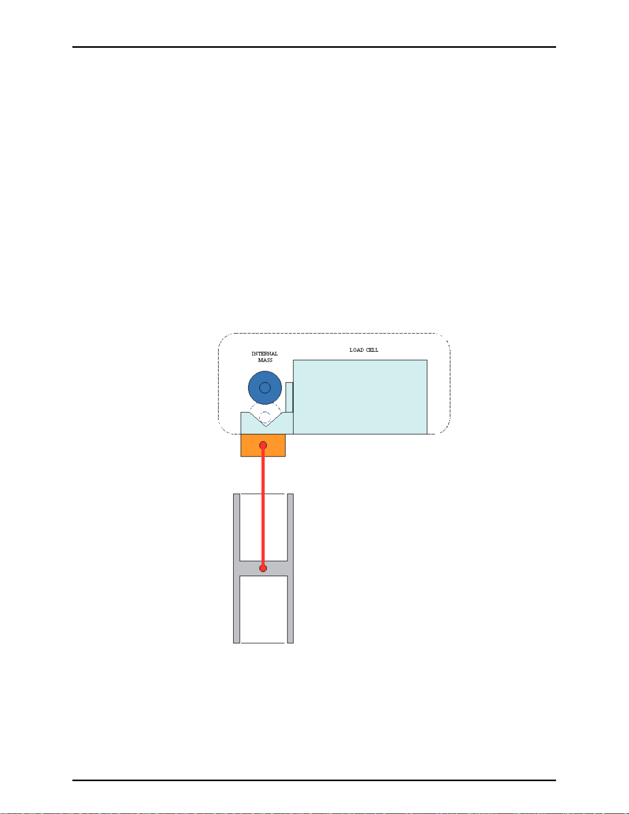
2.3 LOAD CELL
The load cell has a measurement capacity equivalent to 2 300 g with a resolution of 1 mg. A force
equivalent to 1 500 g is used for the measuring range. The rest of the measurement capacity is used to
compensate for the mass of the piston and its carriage assembly.
During the manufacturing process, the load cell is calibrated and linearized within the required specifications.
Load cell accuracy is maintained by the ability to frequently zero null force error, and by making slope
corrections using an internal calibration mass. The FPG is specifically designed to allow the internal
calibration mass to be measured in perfect alignment with the piston and cylinder (see Figure 7).
The ma
true mass value. When the mass is lowered in the operating conditions of the FPG, a correction factor is
determined to cause the buoyancy corrected output of the load cell to be equivalent to this true mass
value. Sensors internal to the FPG measure pressure, temperature and humidity around the load cell to
make the buoyancy correction. Since zeroing and running the internal calibration are integral parts of the
FPG, pneumatic valves are included with the FPG to allow the system to automatically set the necessary
conditions to perform each task.
ss value of the internal calibration mass is accurately determined and stored in FPG Tools as a
Figure 7. Internal Calibration Mass Alignment
The FPG configuration subjects the load cell to the lubricating pressure which significantly differs from
typical atmospheric conditions. The optimum environmental conditions of the balance are specified by
the manufacturer as temperature between 10 and 30 °C with relative humidity of 40 to 70 %. Typical
laboratory conditions yield the necessary temperature range. The humidity is, however, controlled to
approximately 50 % by a bubbling system internal to the FPG. FPG Tools will display a warning message
if these conditions change beyond these limits. Low humidity values cause electrostatic effects on the
load cell which have adverse influence on the zero stability of the load cell.
Page 13 © 2007 DH Instruments, a Fluke Company
Page 26

FPG8601™/VLPC™ OPERATION AND MAINTENANCE MANUAL
2.4 LUBRICATION PRESSURE
Two different values of lubricating pressure are used depending on whether the FPG is working in gauge
or absolute measurement modes. These two pressures are supplied by two independent regulators
which can be connected by valves depending on the measurement mode. In gauge measurement mode,
the nominal lubricating pressure value is 140 kPa absolute which is about 40 kPa gauge. In absolute
measurement mode, the nominal lubricating pressure is 40 kPa absolute. The absolute mode lubricating
pressure reduces the lubricating flow which allows the reference vacuum or back pressure to be less than
a Pascal with most standard vacuum pumps. Higher power vacuum pumps can be used to greatly
reduce this pressure.
The lubrication pressure affects buoyancy forces on the load cell and the piston-cylinder as well as
creating a change in the dragging force on the piston-cylinder. The buoyancy effect is characterized
during the manufacturing process by varying the lubrication pressure and recording the change in load
cell output relative to the change in lubrication pressure. The drag effect is determined by maintaining a
constant lubrication pressure and changing the reference (see Section 2.7). Each time the FPG is
zeroed, the
the lubrication pressure and reference pressure since the last zero. A high quality pressure regulator built
into the FPG prevents this pressure from changing significantly when proper system pressure is applied.
As a result, the influence of the lubrication pressure on the FPG is maintained at a minimum.
The FPG is intended to be used in ambient conditions which means that the gas present in the upper and lower
measurement chambers is ambient air. It is therefore desirable to use air as the lubricating medium.
This avoids gas mixtures in the measurement chamber. However, FPG Tools supports N
Prior to changing gases, the system must be thoroughly purged. This includes the lubricating volume and
the test and reference ports of the FPG. Lack of knowledge of the constitution of the test gas complicates
the calculation of density needed to make fluid head corrections.
se effects are also set to zero. Therefore, changes in these forces are only due to changes in
as a lubrication gas.
2
2.5 VACUUM REFERENCE PRESSURE
The FPG8601 inherently measures differential pressure. When the lower mounting post is exposed to
atmosphere, the FPG measures gauge pressure. If the lower mounting post is exposed to a vacuum, the
FPG measures absolute differential pressure. To measure absolute pressure, the residual vacuum
pressure in the lower mounting post must be added to the FPG differential pressure. As a result, a high
accuracy low range sensor is included with the FPG to define absolute pressure.
Depending on the vacuum pumps used, the residual vacuum pressure will be less than 1 Pa. At this
pressure, span error in the vacuum sensor does not significantly impact the overall uncertainty of
the FPG. A 0.5 % span error at 1 Pa results in a .005 Pa error. However, zero offset in the sensor is
directly transferred to the zero offset of the FPG. Therefore, the zero of the sensor should be checked
frequently (see Section 8.3). A pneumatic valve is provided to isolate the vacuum reference sensor when
the FPG is n
change from vacuum to atmosphere. FPG Tools automatically isolates the sensor depending on the
current mode of operation.
ot under vacuum. This helps to reduce zero drift by avoiding the shock associated with a
© 2007 DH Instruments, a Fluke Company Page 14
Page 27
2. FPG THEORY OF OPERATION
2.6 SIMPLIFIED FORMULA FOR CALCULATING DIFFERENTIAL PRESSURE
The calculation of differential pressure is made following the basic formula:
ΔP = F/A
eff.
(θ)
VARIABLE DEFINITION
ΔP
F Force measured by the load cell in counts (1 count = 1 mg).
A
(θ)
eff.
Differential pressure between the upper and lower chambers in Pa.
Effective area of the piston-cylinder at the operating temperature, θ.
The value is expressed in m
2
.
The force, F, measured by the load cell when it displays a number of counts, N, can be calculated using a
calibration coefficient, K
, following:
cal
F = K
cal.
. N
VARIABLE DEFINITION
K
Calibration coefficient of the load cell. This value contains any
cal.
N Number of counts output by the load cell representing the force
necessary slope correction for the load cell determined by the
internal calibration (see Section 5.3). The air density and local
gravit
y present at the time the calibration was performed are also
quantified by this value. The calibration factor is expressed in
Newtons/ Count (1 count = 1 mg).
measured. One count represents the force corresponding to a
mass of 1 mg loaded on the load cell under the calibration
conditions.
The effective area of the piston-cylinder at temperature θ, can be expressed using its value at 20 °C and
the linear thermal expansivity of the piston and the cylinder materials following:
A
(θ) = A
eff.
(20°C) . [ 1+ ( αp + αc ) . ( θ - 20 ) ]
eff.
VARIABLE DEFINITION
αp
αc
Linear thermal expansivity of the piston in K
Linear thermal expansivity of the cylinder in K
-1
.
-1
.
The piston and the cylinder are made of tungsten carbide therefore the thermal expansion coefficients are
the same; α
+ αc = 9 . 10-6 K-1. FPG Tools provides a single entry value for this combined effect in the
p
FPG calibration setup (see Section 6.6.3).
The sim
plified formula for the calculation of the differential pressure can therefore be expressed as:
ΔP = K
cal.
. N / A
(20°C) . [ 1+ ( αp + αc ) . ( θ - 20 ) ]
eff.
Page 15 © 2007 DH Instruments, a Fluke Company
Page 28

FPG8601™/VLPC™ OPERATION AND MAINTENANCE MANUAL
In gauge measurement mode, the differential pressure is defined as being the difference between the
pressure in the upper chamber at the reference level of the mounting post and the pressure at the
corresponding level in the ambient air.
In absolute measurement mode, the differential pressure is defined as being the difference between the
pressure in the upper chamber at the reference level of the mounting post and the reference vacuum in
the lower chamber measured by the capacitance diaphragm gauge.
The reference pressure is defined as the pressure surrounding the piston when the load cell is in a zero
condition with the upper and lower chambers in by-pass condition. Therefore, the reference pressure is
atmospheric pressure in gauge mode and vacuum in absolute mode.
2.6.1 REFERENCE LEVEL
The reference level of the mounting post is defined as the height at which a variation of
density in the upper chamber will not affect the differential pressure measurement.
This position depends on the internal geometry of the piston in the upper chamber, in this
case, the piston is hollow. The position of the reference level of the FPG is 25 mm above the
center of the piston. This is approximately the bottom of the upper mounting post (see Figure 3).
2.7 CORRECTIONS
The simplified formula of differential pressure is valid only in the special case where the conditions of the
gas surrounding the load cell and the piston do not change from the time the mobile assembly (made up
of the piston and its carriage) is zeroed and the time the differential pressure measurement is made.
Although the FPG is designed to keep these conditions very stable, it cannot be assumed that they are
constant. Therefore corrections are made to compensate for the associated force changes. The force of
the differential pressure acting on the piston is affected by three different quantities: δN1, δN2 and δN3.
FPG Tools displays these corrections real time on the <Diagnostics Display> windows (see Section
6.3.7). Figure 8 displays each of these quantities.
tare and in operation after tare. N
represents the force on the load cell at the time of tare. N represents
0
This figure shows the forces on the system, both at
for force on the load cell in operation after tare.
Since the effects of buoyancy and drag at the time of tare are included when the FPG is zeroed, it is only
necessary to correct for changes in these forces due to changes in conditions after the time of tare (zero).
A δ precedes each of the corrections because they are derived from changes of conditions since the last
tare. FPG Tools provides warnings to prevent significant changes in each of the correction factors in
order to limit the magnitude of overall correction (see Section 6.6.4).
2.7.1 δN1
If the lubricating pressure which surrounds the load cell, the piston carriage and the piston
changes after the tare is executed due to drift of the lubricating pressure regulator or
temperature of the lubricating gas, the corresponding change in buoyancy force will affect the
force on the load cell. This change in force is quantified by δN1. δN1 is a function of the
buoyancy force coefficient, K
pressure and subtracting the effect due to changes in the drag force (see Section 2.7.2).
is calculated using K
δN1
zero (see Section 11.3.3).
, which is determined experimentally by varying the lubrication
b
and the change of the lubrication pressure since the last system
b
2.7.2 δN2
Due to a small amount of asymmetry of any piston-cylinder assembly, the difference between
the lubricating pressure and the reference pressure surrounding the piston creates a net
viscous drag force that acts on the piston. If this differential pressure changes after the tare
has been executed the drag force changes and the force on the load cell will be affected.
To determine δN2, a drag force coefficient, K
by varying the reference pressure while holding the lubrication pressure constant.
Subtracting the buoyancy changes due to the change in reference pressure (see Section 2.7.3),
© 2007 DH Instruments, a Fluke Company Page 16
, is determined experimentally. Kd is determined
d
Page 29
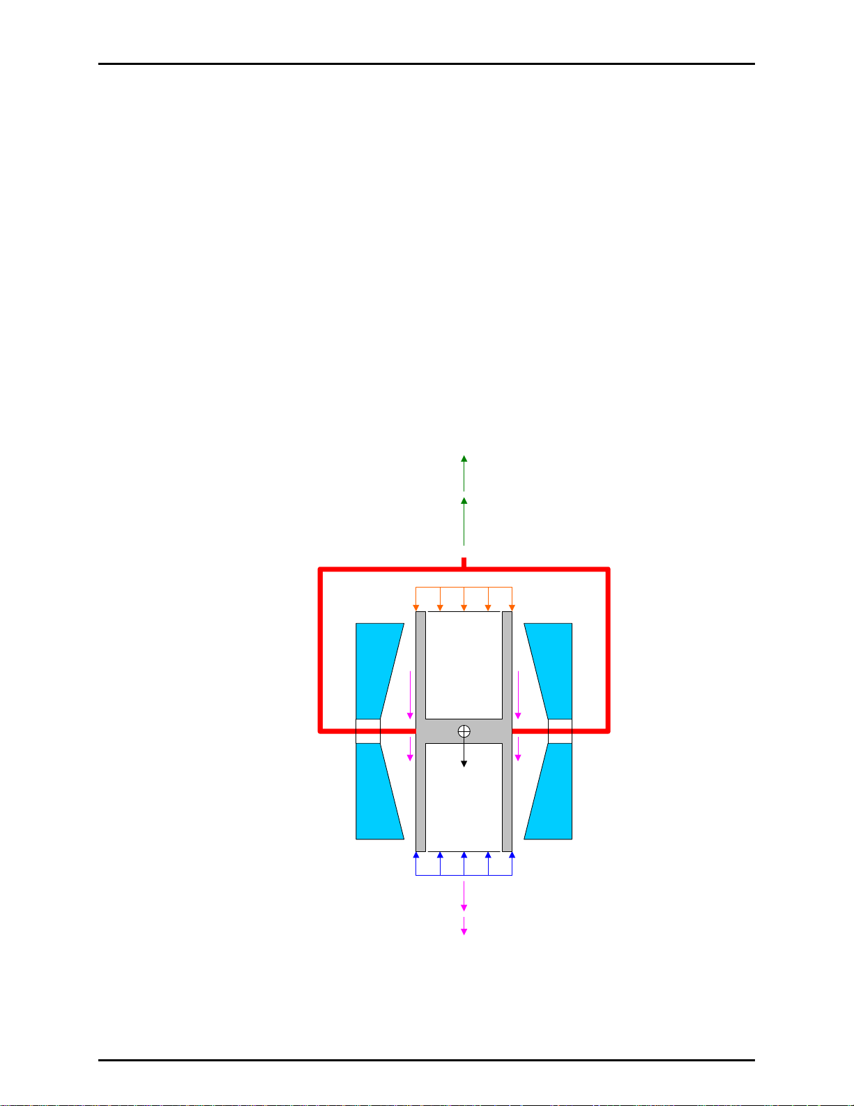
2. FPG THEORY OF OPERATION
Δ
Δ
N
N
Δ
the remaining effect is the change in force due to drag on the piston. δN2 is calculated using
and the change in the difference between the lubrication pressure and the reference
K
d
pressure (see Section 11.3.3).
2.7.3 δN3
Buoyancy due to the reference pressure gas that surrounds the piston exerts a force that acts
on the piston. If the FPG reference pressure changes after the tare is executed, the corresponding
change in the buoyant force affects the force on the load cell. In absolute mode the reference
pressure is on the order of a few Pascal. Buoyancy effects related to changes in such a low
pressure are insignificant. Therefore, δN3 = 0 for absolute mode.
In gauge mode the reference pressure is atmosphere. Buoyancy effects due to changes in
atmosphere can have a measurable effect on the output of the FPG. Like the other
correction terms, δN3 quantifies the change in buoyancy due to the change in atmosphere.
Typically atmospheric changes are quite small so the change in buoyancy will also be small.
The effect of δN3 is most apparent when the FPG is zeroed in gauge mode, then the system
is changed to absolute mode without re-zeroing (not a recommended practice). The change
in reference pressure is equal to one atmosphere. The change in buoyancy force associated
with this large change is the correction. Since zeroing in each mode of operation is standard
procedure for the FPG, this extreme situation does not occur.
=mg + F
0
F
B,L
F
B,L
(δN1)
mg
F
B,R
F
B,R
(δN3)
Figure 8. FPG Forces
+ F
+ F
B,L
B,R
D
P
*A
θ
high
F
D
F
D
(δN2)
P
*A
θ
ref
Page 17 © 2007 DH Instruments, a Fluke Company
Page 30

FPG8601™/VLPC™ OPERATION AND MAINTENANCE MANUAL
2.8 COMPLETE DIFFERENTIAL PRESSURE EQUATION
The combination of all corrections along with the simplified pressure equation yields the complete differential
pressure equation for the FPG. An exploded view of all FPG calculations is detailed in Section 11.3.
ΔP =
. ( N + δN1 + δN2 + δN3 ) / [A
K
cal.
(20°C) . [ 1+ ( αp + αc ) . ( θ - 20 ) ]]
eff.
In gauge measurement mode, this differential pressure is equal to the gauge pressure of the FPG.
In absolute mode, the residual vacuum pressure measured by the vacuum reference sensor is applied to
the calculated differential pressure to obtain the absolute pressure of the FPG.
© 2007 DH Instruments, a Fluke Company Page 18
Page 31

3. VLPC THEORY OF OPERATION
.
33.
VVLLPPC
C
T
HHEEOORRYY OOFF
T
O
PPEERRAATTIIOON
O
N
3.1 OVERVIEW
The VLPC (in conjunction with the FPG) generates low pressures in gauge and absolute modes (0 to 15 kPa).
The purpose of the VLPC is to set and stabilize pressure as read by the FPG so that the VLPC/FPG
combination can be used to set user specified target pressures. The [Config], [System Setup],
<Enable VLPC> option must be checked to allow FPG Tools to control all aspects of the VLPC based
(see Section 6.6.2.1).
The gen
restrictions depending on the range of pressure to be controlled. The pressure drop across the restriction
is the differential pressure in gauge mode. In absolute mode, the pressure at the high pressure sense is
the absolute pressure generated.
eral operating principle of the VLPC is to generate a stable flow through one of a number of
The VLPC is a very sensitive pressure controller. In gauge mode, subtle changes in ATM may affect the
control of the VLPC. Shutting doors, turning on air conditioning, etc. may cause momentary
fluctuations in the controlled pressure. Absolute mode is not sensitive to these conditions. The
effect on control is more significant as the volume attached to the upper mounting post of the FPG
increases. If atmospheric disturbances cannot be avoided, a direct connection of a DUT to the FPG
that minimizes the volume will optimize control. Regardless, because the FPG and DUT(s) are seeing the
same pressure, the effect of fluctuations can be minimized by increasing the averaging time when
taking data.
Based on pressure readings from the FPG, the VLPC can control pressures within ± 0.020 Pa + 30 ppm
of the range selected. Use [Config], [Settings] (see Section 6.6.1) to define the actual pressure ready
rion. The range maximums (Pa) are approximately defined in Section 6.6.1.
crite
for absolute mode actually defines the lowest absolute control range. This table was generated using a
D16b vacuum pump.
Table 1. Nominal VLPC Ranges
ABSOLUTE
(Pa)
5 15
150 150
1 500 1 500
5 000 3 000
15 000 15 000
GAUGE
(Pa)
The vacuum pump used
Page 19 © 2007 DH Instruments, a Fluke Company
Page 32
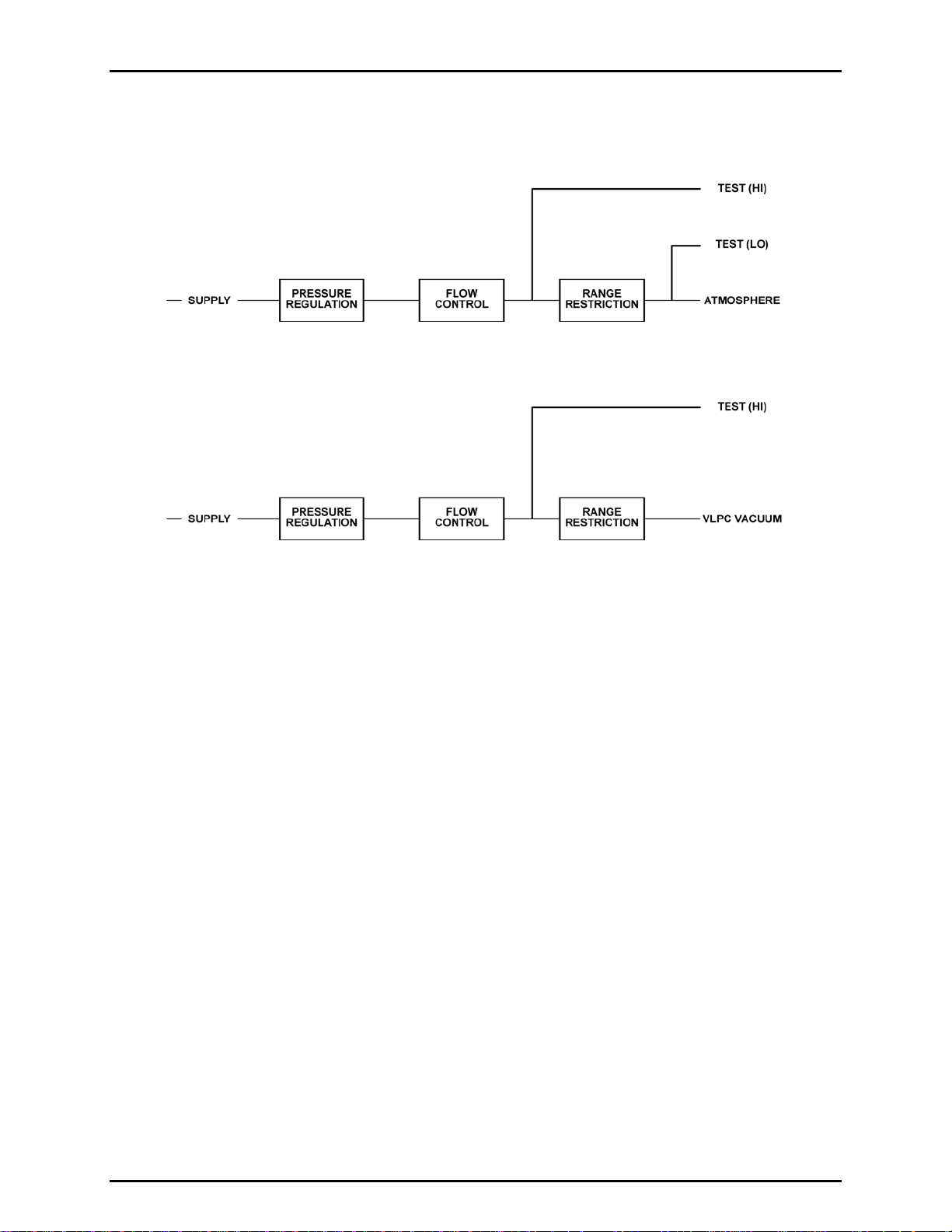
FPG8601™/VLPC™ OPERATION AND MAINTENANCE MANUAL
The block diagrams below illustrate absolute and gauge mode pressure and flow.
Figure 9. Gauge Mode VLPC Block Diagram
Figure 10. Absolute Mode VLPC Block Diagram
The breakdown of the system is in the following areas: supply and regulation, flow control, range
restrictions, connections and control.
3.2 SUPPLY AND REGULATION
The FPG and VLPC must use the same gas medium. Typically this is bottled N2, however dry air is also
supported. There are additional considerations for initial setup and operation of the FPG in gauge mode
with a nitrogen source. Whenever changing gas mediums, the FPG and VLPC must be thoroughly
purged (see Section 4.12).
The supply g
as to the VLPC must be clean, dry air between 700 and 840 kPa gauge (100 and 120 psig),
with stability of ± 1 %. For the VLPC to provide stable pressures, the inlet pressure to the flow controllers
must be stable. After passing through a 0.5 micron filter, the VLPC supply is regulated down to 200 kPa
gauge by a large diaphragm 350 kPa Tescom regulator. The output of the Tescom regulator feeds an
LNI regulator set at 100 kPa above the LNI reference. The LNI reference is downstream of the range
restrictions – a location that is effectively atmosphere for gauge control and vacuum for absolute control.
A 100 kPa differential pressure has been found to produce the most stable flow across the MFCs.
3.3 FLOW CONTROL
The flow is controlled by two mass flow controllers (MFC) in parallel. The full scale flow for the VLPC is
500 sccm. A coarse MFC (500 sccm) is used in parallel with a fine MFC (25 sccm) to achieve a wide
range of flow with very fine control resolution. After controlling to a pressure near the target, the high flow
MFC is set to a constant flow while the low flow, 25 sccm, MFC performs the fine control to achieve and
maintain pressure within specifications.
© 2007 DH Instruments, a Fluke Company Page 20
Page 33
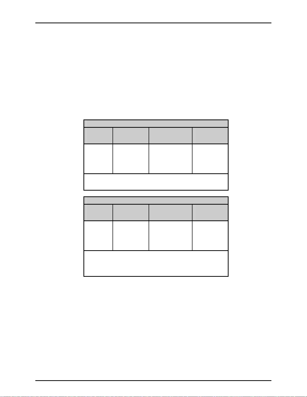
3. VLPC THEORY OF OPERATION
3.4 RANGE RESTRICTIONS
Given a stable controlled flow, the pressure is defined as the drop across a given range restriction. The thermal
and mechanical stability of the restrictions is critical to the stability and controllability of pressure.
The five lowest conductance (highest pressure range) restrictions are accomplished with a piston and
block configuration very much like a 5 slm DHI molbloc. The highest conductance (lowest pressure
range) restriction (labeled R1) is used in absolute mode only. R1 is accomplished by flowing through a
short section of 16 mm ID tubing and a large vacuum valve in a manifold before attaching to KF-25
vacuum tube and a vacuum pump.
The following tables list the pressures available for ranges in gauge and absolute modes.
Table 2. Nominal VLPC Ranges, 15 kPa Unit
ABSOLUTE RANGES
RANGE
R0
R1
R2
R3
R4
*Note: The lowest pressure for a given range occurs when the pressure is set to
0 in that range. The pressure is generated by the flow of lubricating
gas from the upper chamber through the range restriction selected.
RANGE
R2
R3
R4
R5
R6
*Note: The lowest pressure for each range in gauge mode is 0. The bypass
valve is opened whenever the pressure is set to 0 in any gauge
range. The conductance of the bypass in gauge mode is low enough
that there is no measurable pressure difference due to the flow of
lubricating gas from the upper chamber.
LOWEST
PRESSURE*
[PA]
0.8
0.8
50
75
100
LOWEST
PRESSURE*
[PA]
0
0
0
0
0
LOWEST
CONTROLLABLE
[PA]
100
280
650
GAUGE RANGES
LOWEST
CONTROLLABLE
[PA]
0.1
0.5
4
9
50
RANGE
MAXIMUM
[PA]
1
3
5
150
1 500
5 000
15 000
RANGE
MAXIMUM
[PA]
15
150
1 500
3 000
15 000
3.5 CONTROL
VLPC control is designed to set the pressure to the target value and control continuously to keep
pressure within the hold limit and as close to the target value as possible. The advantage of this type of
control scheme is that the final pressure achieved will be very close to the target value. However, control
noise can lead to errors unless the FPG pressure (and DUT pressure if available) is averaged. For this
reason FPG Tools contains an averaging feature for running tests and logging data (see Sections 6.4.2,
6.7.4).
The co
based on pressure readings. The FPG pressure is used for all control readings all ranges for optimum
control and resolution.
Page 21 © 2007 DH Instruments, a Fluke Company
ntrol of both the coarse (high flow) and fine (low flow) MFCs is accomplished with PID control
Page 34
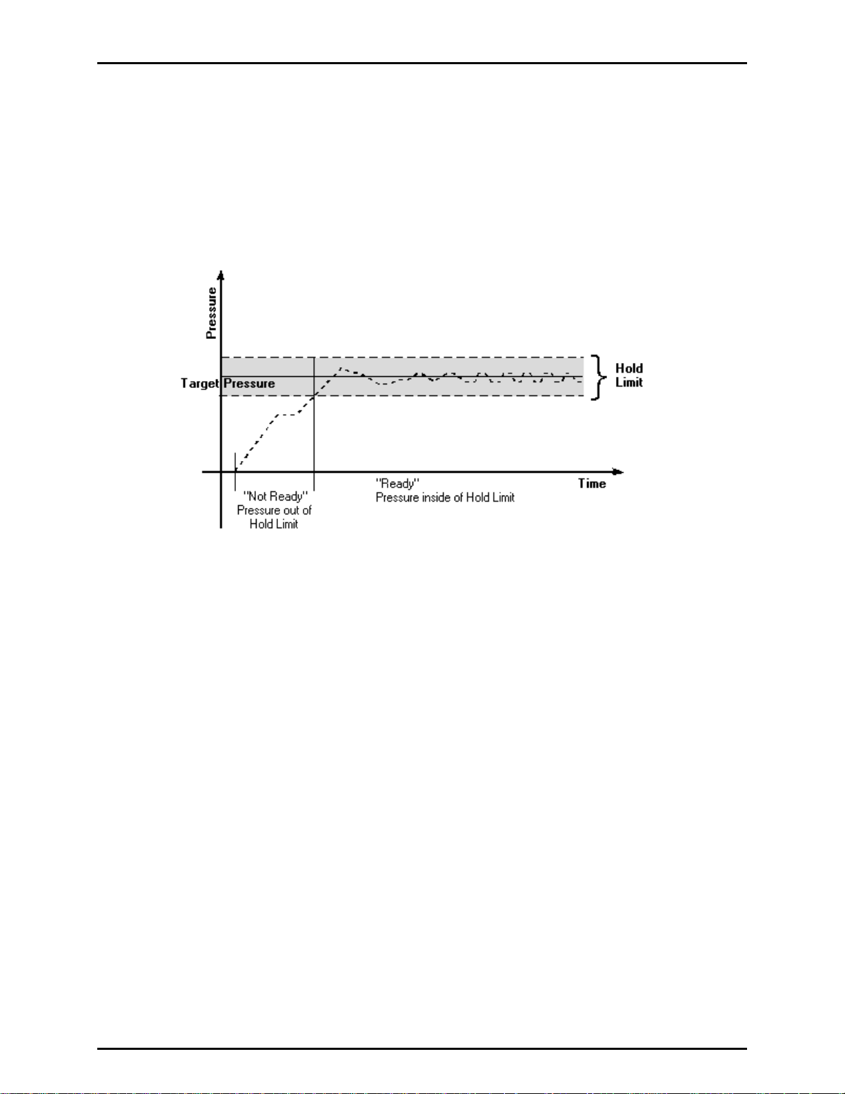
FPG8601™/VLPC™ OPERATION AND MAINTENANCE MANUAL
3.6 READY/NOT READY
Regardless of the current control state of the VLPC, any information logged in the system status will force
a "Not Ready" condition (see the <Status> values in Section 6.3.7). Provided this is not the case, a
"Ready" cond
the hold limit specified by the <Hold Limit> option in <Settings> (see Section 6.6.1). Figure 11
graphically portray
the "Ready" condition is based on the <Stability Setting>.
ition from a VLPC perspective is obtained while controlling when the FPG pressure is within
s the ready criterion while the VLPC is controlling. When the VLPC is not controlling,
Figure 11. VLPC Ready Criterion
© 2007 DH Instruments, a Fluke Company Page 22
Page 35
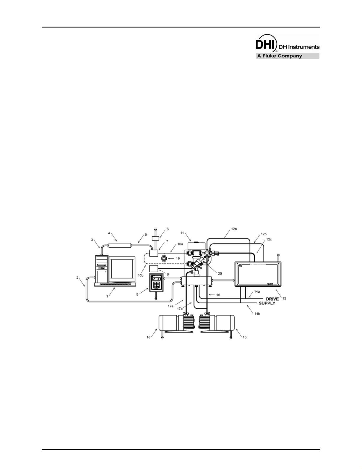
4. GETTING STARTED
.
44.
G
EETTTTIINNGG
G
S
TTAARRTTEED
S
D
4.1 OVERVIEW
The topics in this section describe the basic requirements of setting up FPG Tools PC software and the
FPG/VLPC hardware. After the system is properly set up, these steps should be required for
maintenance and troubleshooting purposes only.
Figure 12 is a complete FPG8601 calibration system schematic. Refer to this figure as needed when
setting up the FPG and following procedures in this section. Figure 4 and Figure 5 describe the
nections on back of the FPG and VLPC.
con
4.2 INSTALLING FPG TOOLS
Insert the installation CD included with the FPG8601 to install FPG Tools. When the CD is inserted it will
automatically execute the FPG Tools installation program. However, if the auto run feature is disabled in
Windows this will not occur. If this is the case, use the [Windows Control Panel], [Add Remove
Programs] feature. To locate this option press the [Start] button on the main task bar, choose
[Settings], then select <Control Panel>. Choose the [Add Remove Programs] option and press the
<Install> button. Follow the prompts of this dialog to install FPG Tools. A new program group with a
shortcut to this manual and FPG Tools software will be added to the program menu of the host PC. To run
FPG Tools, simply click the FPG Tools icon.
1. PC with two RS232 ports 12b. Control low connection
2. PC to FPG8601 serial cable 12c. Control vacuum connection
3. PC to DUT data acquisition serial cable 13. Very Low Pressure Controller (VLPC)
4. DUT data acquisition (DMM, I/F box) 14a. Drive air (valve actuation)
5. Data acquisition to DUT connection 14b. Pressure supply
6. DUT Power Supply 15. VLPC vacuum pump
7. Device Under Test (DUT) 16a. VLPC vacuum connection
8. Capacitance Diaphragm Gauge to measure
residual vacuum in absolute mode
9. FPG8601 local interface and power supplies 18. FPG8601 reference vacuum pump
10a. FPG8601 to DUT “high” side pressure connection 19. DUT isolation valves
10b. FPG8601 to DUT “low” side pressure connection
11. FPG8601
12a. Control high connection
Figure 12. FPG8601 System Schematic
Page 23 © 2007 DH Instruments, a Fluke Company
16b. FPG8601 lubrication vacuum connection
17. FPG8601 reference vacuum connection
20. Vacuum reference sensor isolation valve
(Used in horizontal position only)
Page 36

FPG8601™/VLPC™ OPERATION AND MAINTENANCE MANUAL
4.3 SETTING UP FPG TOOLS
Run FPG Tools by using the FPG Tools icon located in the program group created during the installation.
Before any of the [Run] menu options are used to start the automatic update of the FPG pressure, the
FPG calibration file and initial program configuration must be set up. After this information is correctly set
up, future configuration changes are necessary only to change the existing setup. FPG Tools saves all
setup information so that the last saved configuration is automatically available for each run of the
program. Use the options in the [Config] menu to complete this setup.
Use [Config], [System Setup], <Setup> to specify the current local gravity, calibration gas, vacuum
reference and the FPG RS232 interface settings.
Enable the VLPC if it will be used to control pressure.
Select <Use vacuum reference for absolute mode correction>.
In some cases this information is pre-installed.
Use [Config] [DUT Editor] to set up any DUTs that will be used with the system. This is
an optional task that can be skipped. DUTs can be setup at
any time (see Sections 6.8, 6.6.2.3).
e [Config], [FPG Calibration Setup] to enter all of the FPG specific calibration information
Us
(see Section 6.6.3). This is the most important step in the
softwa
re setup process. Using default information in all
other aspects of the program will not yield invalid pressure
output data. However, an improperly configured FPG
calibration file will always generate inaccurate data. This file
is pre-configured for some FPG installations. If this is the
case, verify that the values displayed match any
documented values provided. If any changes are made, you
must press “Accept” for changes to be saved.
Improper setup of the FPG calibration file will yield invalid pressure output data from
FPG Tools.
When the above information is properly set up, there is no need to repeat these steps unless a new setup
is required. Use the [Run], [Run Monitor] menu choice to begin polling the FPG after all hardware is
properly set up.
© 2007 DH Instruments, a Fluke Company Page 24
Page 37

4. GETTING STARTED
4.4 BASIC FPG HARDWARE SETUP
This process explains critical steps that must be taken prior to using the FPG. The following steps cover
setting the FPG on the calibrating surface, adjusting regulators for proper system pressures, and fine
tuning the system.
Table 3. Equipment for Basic FPG
Hardware Setup
EQUIPMENT
FPG
FPG piston
FPG cylinder
Bottled compressed gas (air or N2)
Regulator (from bottle pressure in / 700 kPa out)
Personal computer
RS232 cable
Various tube’s and adaptors
2.5 mm Allen wrench
Distilled water
Place the FPG on the site table with the mounting post facing the back of the table.
Shop air 700 kPa (100 psi)
Take care not to cause any shock to the FPG by bumping or dropping the unit on the desk. The FPG
contains extremely sensitive measuring components that must be replaced when damaged.
Place the FPG terminal on the table to the right of the FPG.
Add distilled water to the FPG bubbler system. (See Section 8.2).
Connect the FPG terminal to the FPG terminal port on the rear panel of the FPG using the supplied
25-pin cable.
Connect electrical power to the FPG terminal.
Connect an RS232 cable from COM1 of the FPG to an RS232 communications port on the PC.
Level the FPG using the two rear adjustable feet. Use the bubble level on the top of the FPG during
the leveling process.
Connect the supply bottle to the inlet of the external regulator that will be adjusted to 700 kPa (100
psi). It is recommended to have at least 3.5 MPa (500 psi) in the bottle. This will ensure that the
bottle pressure will always be greater than 700 kPa (100 psi).
Do not turn the pressure on the unit at this time. When the FPG is shipped, the piston and cylinder
come detached from the unit. Pressurizing the unit prematurely could introduce contaminates into
the system.
Attach the outlet of the external 700 kPa (100 psi) regulator, to the “lubrication pressure” port on the
back of the FPG.
Page 25 © 2007 DH Instruments, a Fluke Company
Page 38

FPG8601™/VLPC™ OPERATION AND MAINTENANCE MANUAL
4.5 SETTING UP THE PISTON-CYLINDER
When the piston-cylinder is shipped, it comes in a hard plastic molded case to keep it firmly in place.
A 2.5 mm counter sink screw is in the lower section of the bullet case. By removing this screw,
atmospheric pressure is introduced into the piston-cylinder case. This will allow the piston-cylinder to be
removed easily.
Remove piston-cylinder bullet case from the shipping package.
Remove the 2.5 mm screw on the lower (flat) section of the bullet case.
Place the bullet case on a stable surface with the flat surface against the table.
Grip the upper and lower portion, and gently twist the upper portion in a counter-clockwise position.
Remove the upper section of the bullet case.
Put on gloves to protect the piston-cylinder from contamination.
Cup the exposed piston-cylinder assembly with one hand and turn the piston-cylinder and lower
section of the bullet case upside down supporting the piston-cylinder with the cupped hand.
Slide the lower section off of the piston-cylinder.
Place the piston-cylinder on to a stable soft surface (lint-free towels).
Re-attach the screw back in the lower section of the bullet case.
Mate the upper and lower section of the bullet case.
Clean and assemble the piston-cylinder then insert it into the mounting post. These steps are
described in Section 7.
4.6 CONNECTING THE FPG MANIFOLD AND VALVES
The bypass/control manifold is connected to the right side of the FPG8601. This part is essential for
automated operation of the system. Follow the steps below and refer to Figure 13 for information on
necting the manifold.
con
Make sure the lower mounting post is properly secured on the FPG (see Section 7.6). The PRT and
pressure connections should be made prior to continuing.
Connect the FPG manifold to the mounting post. Use Figure 13 for proper orientation.
© 2007 DH Instruments, a Fluke Company Page 26
Page 39
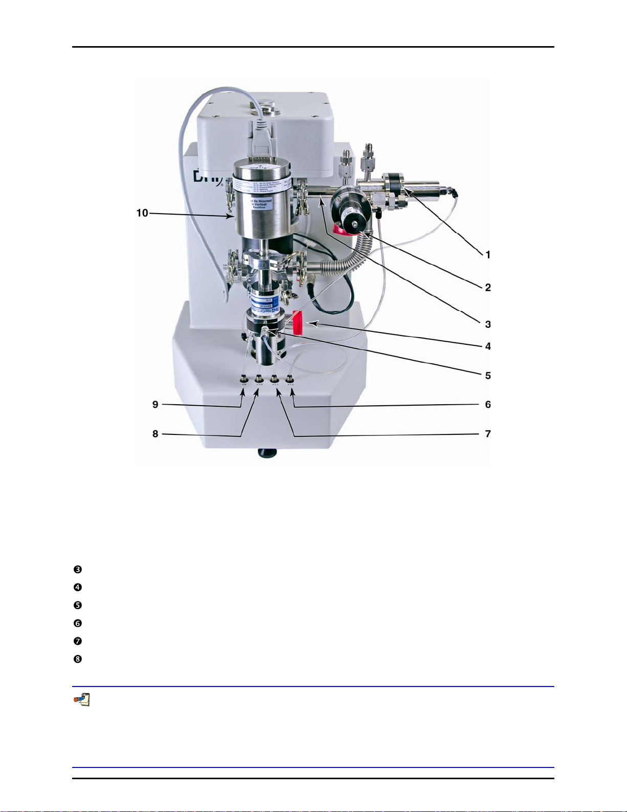
4. GETTING STARTED
1. Bypass Valve (10) 6. Valve Driver (12)
2. Vacuum Control Reference Valve (11) 7. Valve Driver (11)
3. FPG8601 Manifold 8. Valve Driver (10)
4. Vacuum Valve (9) 9. Valve Driver (9)
5. Vacuum Reference Isolation Valve 10. Vacuum Reference Sensor
Figure 13. FPG8601 Manifold Connection
Connect the normally closed pneumatic valve to the bottom of the lower mounting post.
Connect a piece of the supplied flexible tubing to the drive port of each valve.
Connect valve driver 9 to the vacuum reference valve with the supplied tubing.
Connect valve driver 10 to the bypass valve with the supplied tubing.
Connect valve driver 11 to the vacuum control reference valve with the supplied tubing.
Connect the open end of the reference vacuum sensor valve to the front of the mounting post. Make
sure the vacuum reference sensor is in the vertical position.
Always mount the vacuum reference sensor in the orientation used for zeroing. A significant zero-shift can
occur when the sensor is not mounted in the orientation in which it was zeroed (see Section 8.3). It is
recommended that the sensor be zeroed in the vertical orientation. When zeroed horizontally, the rotation
of the sensor also affects the zero. This makes it difficult to mount remove and remount sensor without
affecting the zero.
Page 27 © 2007 DH Instruments, a Fluke Company
Page 40
FPG8601™/VLPC™ OPERATION AND MAINTENANCE MANUAL
Make sure the electrical connector of the sensor is also connected to the port on the upper left of the
FPG base.
Connect valve driver 12 to the valve attached to the vacuum sensor with the supplied tubing.
4.7 SETTING UP THE FPG FOR OPERATION
The FPG can be set up to use both gauge and absolute pressure measurement modes on demand.
If the following steps are performed, simply using the [Units], [Gauge Mode] (or [Absolute Mode])
option is all that is required to change the current pressure measurement mode (see Section 6.9.2).
Since the i
this procedure are related to setting up absolute measurement mode.
nitial power up condition of the FPG is gauge measurement mode, the majority of the steps in
Connect the FPG manifold to the mounting post (see Section 4.6).
Attach the KF25 pneumatic valve to the bottom of the FPG lower mounting post (this may already
be attached). Connect the actuation line of the valve to driver 9 (V9) on the far left of the FPG
base.
If you are only going to use the FPG in gauge mode only you do not have to continue with the following
steps in this procedure. Absolute mode requires two vacuum pumps for reference pressure and
control pressure.
Attach a KF25 tee to the D16b vacuum pump’s inlet port.
Attach a 1 000 mm KF25 bellows tube to the vertical port on the KF25 tee.
Attach the opposite end of the KF25 bellows tube to V11 on the FPG manifold.
Attach the KF25 x 1/4 in. Swagelok adaptor to the remaining port on the KF25 tee.
Install the vacuum bleed kit assembly on the 1/4 in. Swagelok fitting.
Route a 1/4 in. PFA tube from the 1/4 in. Swagelok fitting on the other end of the bleed kit assembly
to the VACUUM port on the back of the FPG.
Install the KF25 by KF40 vauum elbow connecting to the KF25 fitting on valve 9 on the FPG mounting
post and routing it through the hole in the bench. Connect the elbow to the bench using the holding
collar and brackets.
Attach the turbo pump to the vacuum tube that extends down through the bench using a KF40 flange
and a the KF40 centering ring with a screen. Orient the pump so that its lateral KF16 port is facing
towards left (as viewed from the front of the bench).
Attach turbo pump controller cable (on turbo pump controller) to the turbo pump.
Install PFA vent bleed tube between the adaptor and the bulkhead on the rear of the turbopump
controller.
Install a KF16 x KF25 adaptor onto the turbo pump KF16 lateral port.. Attach a KF25 plastic hose
from the adaptor to the roughing vacuum pump.
© 2007 DH Instruments, a Fluke Company Page 28
Page 41

4. GETTING STARTED
4.8 SETTING UP THE VLPC
The following procedure will connect the VLPC to the FPG. The VLPC and the FPG will use the same
bottle and downstream regulator for the supply pressure. When placing the VLPC next to the FPG,
ensure that the provided PFA tubes will reach the appropriate parts. If the tubes do not reach, move the
VLPC closer to the FPG. It is assumed that the FPG piston has already been inserted into the mounting
post at this point. Refer to Section 4.4 for VLPC connections.
Place the VLPC on the right side of the FPG approximately six inches away.
Attach the Test (Lo) port from the VLPC to the Control Low port on the FPG manifold. Use the 1/4 in.
PFA tubing with the VCO connection on one end. Before connecting the VCO connection, ensure
that the O-rings are attached to the Test (Lo) port on the back of the VLPC.
Attach the Test (Hi) port from the VLPC to Control High port on the FPG manifold. Use the 1/4 in.
PFA tubing with the VCO connection on one end. Before connecting the VCO connection, ensure
that the O-rings are attached to the Test (Hi) port on the back of the VLPC.
Attach the FPG Vacuum port from the VLPC to Vacuum port on the FPG manifold. Use the 3/8 in.
PFA tubing with the VCO connection on one end. Before connecting the VCO connection, ensure
that the O-rings are attached to the FPG Vacuum port on the back of the VLPC.
Attach the 700 kPa (100 psi) regulated pressure to the “Supply” port on the back of the VLPC. Do
this by using 1/4 in. PFA tubing that has been teed off from the output of the regulator downstream
from the bottle.
Attach drive air to the external port labeled “Drive Pressure” on the rear panel of the VLPC. The drive
pressure should be between 620 to 760 kPa (90 to 110 psi).
4.9 INTRODUCING GAS TO THE FPG
When the FPG is vented or the bottle has been turned off, the lubrication pressure must be reintroduced.
The steps below describe the proper sequence for a safe introduction of gas to the FPG. If not done
properly, a reverse pressure situation can be created that can contaminate the system.
Introduce drive air to the VLPC and FPG.
Make sure that the 700 kPa (100 psi) regulator is shut off before turning the bottle pressure on.
Turn on the bottle pressure.
Adjust the regulator to 700 kPa (100 psi). The gas will flow through the water in the bubbler.
The noise caused by the gas flow through the bubbler is normal. The lubrication gas flowing into the
lubricating volume and the surrounding piston creates the bubbles. By forcing the gas through the
bubbler, the FPG is capable of controlling the humidity of the gas regardless of the humidity of the
source gas.
The gas will fill the lubricating volume to approximately 40 kPa (5.8 psi) above atmosphere.
Start FPG Tools software (if not already active) and choose [Run], [Run Monitor].
Verify that the FPG is level. Use the bubble level on the top of the FPG and make adjustments with
the rear feet as necessary.
Page 29 © 2007 DH Instruments, a Fluke Company
Page 42

FPG8601™/VLPC™ OPERATION AND MAINTENANCE MANUAL
4.10 CONNECTING A DUT
The three measurement modes that the FPG can measure are gauge, absolute, and absolute differential.
Each of the measurement mode setups are described in the following sections. Realize that the FPG can
be set up to run all modes by following the measurement mode setup procedure (see Section 6.9.2).
If this proce
of operation. See Section 4.11 for details on how to set up a DUT that will be used in the FPG manifold.
dure is followed, only a few toolbar and/or menu options are required to change to any mode
4.10.1 GAUGE MODE
This procedure will allow the calibration of gauge DUTs using the FPG as a primary standard
and the VLPC as the pressure controller.
Attach the Test(+) side of the DUT to the upper left KF16 port, Test (Hi).
If available, attach the Test(-) side of the DUT to the lower left KF16 port,
Test (Lo). This is very important in gauge mode. Subtle changes in ATM will cause
erroneous data if the ports aren't connected together.
If a reference port is available on the DUT attach the connection to the test low port of
the FPG. Doing so will ensure that both the FPG and the DUT will see any changes in
ambient pressure.
It is recommended that a valve be placed, joining the Test(+) and Test(-) ports of
differential DUTs together. This valve will be used to short the DUT’s ports together to
achieve an accurate determination of zero.
4.10.2 ABSOLUTE MODE
This procedure describes how to connect an absolute DUT to the FPG and use the VLPC as
the pressure controller. It is assumed that the FPG and the VLPC have been set up
according to the gauge/absolute setup procedure (see Section 6.9.2) and that the FPG is
ntly running in gauge mode.
curre
Turn the power off of the FPG.
If the vacuum reference sensor is already attached to the FPG there is no need to power
down the FPG. It is best to always leave the vacuum reference electrically connected even when it is
not used. This avoids the delay associated with the warm up time of the sensor.
Attach the vacuum reference sensor to the FPG (see Section 4.6).
Attach KF16 shut-off valves to the test and reference ports of the FPG.
Adding these valves will allow for changing DUTs while keeping the FPG in absolute mode.
Connect the test port of the DUT to the KF16 valve that is attached to the test high port of
the FPG.
© 2007 DH Instruments, a Fluke Company Page 30
Page 43

4. GETTING STARTED
If the DUT requires adaptations that require tubing, use the shortest tube length
possible with an inside diameter of at least 15 mm. If only smaller inside diameter tubing
is available, the test will require longer waiting periods prior to taking a point.
Select <Use vacuum reference sensor for absolute mode correction> under the
[Config], [System Setup] menu on the FPG Tools software. (See Section 6.6.2.1.)
Turn on both vacuum pumps.
Change the FPG to absolute mode by selecting [Units], [Absolute Mode] from the main
menu in FPG Tools (see Section 6.9.2.2).
4.10.3 ABSOLUTE DIFFERENTIAL MODE
This procedure describes the setup of an absolute differential DUT using the FPG as a
primary standard and the VLPC as the pressure control device. To begin, the FPG and the
VLPC must be set up according to the gauge/absolute setup procedure (see Section 4.6) and
the FPG is cu
If you want to be able to measure the reference pressure on the FPG for monitoring
rrently running in gauge mode.
purposes or for thermal transpiration correction, the vacuum reference sensor should be
attached prior to going to absolute mode. Using the vacuum sensor in this mode is
optional. If there is no need to monitor the reference pressure, ignore steps related to
the vacuum reference sensor.
If the vacuum reference sensor is already attached to the FPG there is no need to power
down the FPG.
Turn the power off of the FPG.
Attach the vacuum reference sensor and isolation valve onto the front of the FPG.
Make sure the sensor is vertical..
Power on the FPG.
Observe the warm up time that is required for the reference vacuum sensor
(if necessary).
Determine what type of fitting(s) will be required to adapt from the Test (Hi) port of the
DUT to the KF16 upper left Test (Hi) port on the FPG.
Determine what type of fitting(s) will be required to adapt from the Test (Lo) port of the
DUT to the KF16 tee that is attached to the lower left Test (Lo) port of the FPG.
It is recommended that shut-off valves be placed on the high and low ports of the FPG
(see Figure 12). Adding these shut-off valves will allow a DUT to be changed while keeping
the FPG in absolute mode. In addition, by adding these valves it will be possible to keep
the DUT evacuated of gas while other FPG processes are taking place (zeroing,
purging, etc.).
Attach the DUT Test (Hi) port to the upper left port on the FPG, Test (Hi).
Attach the DUT Test (Lo) port to the lower left port on the FPG, Test (Lo).
Page 31 © 2007 DH Instruments, a Fluke Company
Page 44

FPG8601™/VLPC™ OPERATION AND MAINTENANCE MANUAL
It might be necessary to use tubing in order to attach the DUT to the FPG. If needed,
KF16 bellows tubing is recommended. Tubing of comparable volume and flexibility can
be used.
Most DUTs require a warm-up time before they can be calibrated accurately. Check the
DUT users manual for the proper warm-up time.
Power on the DUT.
Using two tubes and a shut-off valve, connect the DUT’s test and reference ports
together.
For safety reason, shorting the test port to the reference port will ensure that the
differential pressure across the DUT will remain near zero in all conditions. When the test
begins, the DUT's test and reference ports should be isolated using the shut-off valve
between the two ports.
Open the shut-off valve between the high and low port of the DUT.
Turn on both vacuum pumps.
Switch the FPG to absolute mode (see Section 6.9.2.2).
4.11 CONNECTING THE DUT MANIFOLD
This section describes how to setup the optional DUT manifold. If properly setup, the manifold can be
used in gauge, absolute and absolute differential mode with up to 3 DUTs without having to
adjust plumbing. The manifold must be turned on in FPG Tools by using tools on the [Config], [System
Setup], <Options> tab (see Section 6.6.2.2).
The ste
ps below describe what is required to setup the DUT manifold.
Set the manifold on the table so that the two pneumatic valves are closest the left side of the FPG
test ports.
Attach a KF16 15 in. bellows tube to the Test (hi) port on the FPG.
Attach a KF16 15 in. bellows tube to the Test (low) port on the FPG.
Attach the remaining ends of the bellows tubes to the DUT manifold’s hi and low ports.
The two bellows tubes should be parallel to each other.
Fasten the external valve driver cable to the connector labeled “external drivers” on the back of the FPG.
Attach the remaining end of the external valve driver cable to the associated connector on the DUT
manifold.
Attach shop air (regulated to 700 kPa (100 psi)) to the 1/8 in. NPTF fitting on the manifold.
DUTs should be connected to the manifold by adapting as necessary. When possible connect
differential and gauge DUTs to both the high and low ports of the manifold. This ensures that the
DUTs and the FPG are using the same reference pressure.
© 2007 DH Instruments, a Fluke Company Page 32
Page 45

4. GETTING STARTED
4.11.1 SETTING UP THE TURBO PUMP
The turbo pump attached to the manifold will be used in two different situations. First, the
turbo pump will evacuate the entire manifold in order to zero DUTs (see Section 5.6).
Secondly, the turbo pump
the manifold when in absolute mode and the vacuum pump is active. In absolute differential
mode, the vacuum pump is not used (see Section 5.4). FPG Tools only supports the Varian
150 Dry Var turbo m
Place the turbo pump on the bracket beneath the DUT manifold.
Place the ISO-63 sealing clamp on top of the turbo pump.
Place the ISO-63 X 8VCR bellows tubing upon the ISO-63 sealing gasket.
Fasten down the ISO-63 section with the associated ISO-63 clamps.
Adjust the turbo pump platform to the appropriate height.
Place an 8VCR metal gasket between the bellows tube and valve 13 on the DUT manifold.
Tighten the 8VCR nut onto valve 13 by rotating the 8VCR nut clockwise 1/16 of a turn
from finger tight.
Readjust the turbo pump platform if necessary.
will be continuously maintaining a vacuum on the reference side of
olecular pump, model 9699163.
Attach the remote communication cable to the “J4 serial” connector on the turbo pump.
Attach the RS232 9-pin connector to a COM port on the back of the PC. This port must
be specified to activate the pump.
Attach the restriction and vent valve to the vent “nut” on the turbo pump.
Connect the power cable connector for the vent valve to the P1 vent connection on the
turbo pump.
Turn the pump on. The power light should turn on but the pump should not start
spinning. If the pump does begin spinning, the remote communications cable must not be
connected properly.
Use the [Config], [System Setup], <Options> tab (see Section 6.6.2.2) to activate the
pump and to specify the RS232 COM port.
FPG Tools will automatically use the pump as needed. However, the pump can be manually
controlled by using the tools on the <DUT Manifold> display (see Section 6.3.8). The current
speed and current of the vacuum pum
p will display on this form.
4.11.2 CONNECTING THE ION GAUGE
The ION gauge will be used for determining how low the DUT manifold has been pumped
down to when zeroing the manifold (see Section 5.6). The output of the ion gauge can help
to dete
Series 360 ion gauge system is the only supported ion gauge that can be used with FPG Tools.
rmine if the DUT has been pulled down low enough for zeroing. The Granville-Phillips
Attach the DB25 cable from power source to the DB25 connector on the back of the
signal conditioner.
Attach the circular connector cable to the back of the power supply.
Attach the coaxial connector to the signal conditioner.
Attach the DB25 X DB9 adapter to the RS232 DB25 connector on the back of the signal
conditioner.
Attach a 9-pin RS232 cable to the adapter to a COM port on the PC.
Attach the ION gauge cable to the ION gauge.
Note that there is only one orientation that the connector will fit.
Page 33 © 2007 DH Instruments, a Fluke Company
Page 46

FPG8601™/VLPC™ OPERATION AND MAINTENANCE MANUAL
After connecting the ION gauge cable, lock in the protective housing by rotating it
clockwise 1/4 turn.
Use the [Config], [System Setup], <Options> tab (see Section 6.6.2.2) to activate the
ion gauge and to specify the RS232 COM port.
FPG Tools will automatically use the ion gauge when zeroing the DUT manifold. Refer to
the <DUT Manifold> display (see Section 6.3.8) to control the ion gauge and to view the
urrent pressure output.
c
4.12 CHANGING LUBRICATION GAS
To change lubrication gas, the FPG must be shut down (see Section 5.9). All of the basic supply
connections to the FPG must then be set up with the new gas (see Section 4.4).
Press the [Shut Down] icon on the FPG Tools software. Wait until FPG Tools displays
<SHUTDOWN>.
Turn off the regulator that connects the FPG to the supply bottle.
Turn off the supply bottle.
Crack the fitting on the supply port of the FPG. Slowly bleed the supply pressure from the supply port
of the FPG by loosening the Swagelok fitting.
Once the supply fitting is removed, slowly turn the regulator up to release any pressure trapped
between the regulator and the bottle.
Remove line from the bottle.
Change the bottle to the new gas.
Reattach the supply fitting onto the supply port of the FPG.
Make sure that the regulator is turned down (off).
Turn on the bottle.
Adjust the supply regulator to 700 kPa (100 psi).
Press the shut down icon on the FPG Tools software to reset gauge mode operation.
Use the [Config], [System Setup] menu option and locate the <Lubrication Gas> option found on
the <Setup> folder. Select the new gas then press <Accept> to store the change.
4.12.1 PURGING THE LUBRICATING VOLUME WITH A NEW GAS
When lubricating gas species a process of purging must take place. If the purging sequence
is not performed, there will be multiple mixing gases in the lubricating volume. This will cause
the determination of air density to be incorrect as well as affect the zero stability of the load
cell. Refer to Section 11.1 for a complete valve schematic of the FPG.
The FPG should be in gauge mode.
Change the user level mode to factory mode if FPG Tools is not already in factory mode
(see Section 6.10).
Activate valve six on the valve toolbar.
Allow valve six to be active for approximately 15 minutes.
Deactivate valve six on the valve toolbar.
Press the purge toolbar button in order to reach a stable humidity.
© 2007 DH Instruments, a Fluke Company Page 34
Page 47

4. GETTING STARTED
4.12.2 PURGING THE TEST PORT
The test port of the FPG must be purged when using any gas other than compressed air.
When a DUT is changed, ambient air is trapped in the DUT and the test port of the FPG.
This creates a mix of gas in the test port of the FPG, therefore this procedure should be performed
every time a new DUT is used and compressed air is not the FPG lubricating gas. The following
procedure will purge any air that is trapped in the test port, and introduce the new supply gas.
Set a pressure to full scale of the DUT using the <VLPC Interface> window (see Section 6.3.6).
Vent the test pressure using the [Vent] option on the <VLPC Interface> window.
The pressure does not have to be stable for any particular amount of time.
Cycle the two previous steps at least five times.
Alternatively, see Section 6.7.6 for cycling pressure in a test sequence.
Page 35 © 2007 DH Instruments, a Fluke Company
Page 48

FPG8601™/VLPC™ OPERATION AND MAINTENANCE MANUAL
NNOOTTEES
S
© 2007 DH Instruments, a Fluke Company Page 36
Page 49

5. SYSTEM OPERATION
.
55.
S
YYSSTTEEMM
S
O
PPEERRAATTIIOON
O
N
5.1 OVERVIEW
This section describes general operation of the FPG after the system is properly set up. This includes:
all necessary pneumatic supply connections to the VLPC and FPG, control connections between the FPG
and VLPC, the connection of any DUT that may be used with the system, all instruments are powered on
and FPG Tools is in [Run Monitor] run mode (see Section 6.5.2). Refer to Sections 7, 8 and 10 for
informatio
n on maintenance and troubleshooting the FPG.
Always start FPG Tools with the [Run], [Run Monitor] menu option (see Section 6.5.2). This puts the
software in a mode that is very similar to a standalone instrument. The outputs of the FPG and any
connected DUT are automatically polled by the software and all toolbar functions are active. From this
state all basic operations of the FPG can be performed.
5.2 ZEROING THE FPG
The FPG should be zeroed frequently to avoid errors associated with changes in conditions and zero drift.
More specifically, always zero the FPG when: first powered on, after changing measurement mode and
warming up (see Section 6.9.2), before making a comparison with another instrument and when tare
ditions have changed beyond the factory limits (see Section 6.6.4). Because of the importance of this
con
function, a p
FPG, press the [Zero System] toolbar option (see Section 6.6.4). FPG Tools will first set a zero condition
in the
<Tare Values> display window (see Section 6.3.3).
neumatic bypass valve is built into the FPG to allow fully automated zeroing. To zero the
FPG, wait for stability, then activate the new zero data. The active zero results are available on the
5.2.1 ZERO CONDITION
In gauge mode, the zero condition is reached when the bypass valve is open and all pressure
control connections to other instruments are isolated. Basically, the FPG should have the
high and low ports directly connected together with no other pressure influences. FPG Tools
automatically makes the valve adjustments as necessary when possible and vents any
controlled pressure in the VLPC.
The absolute mode zero condition is the same as the gauge condition with the addition of
deactivating the reference port vacuum isolation valve (V9). The reference port vacuum must
be isolated to prevent a bias associated with the natural differential pressure caused by flow
from the upper port through the bypass to the vacuum. The pump does not have to be turned
off while zeroing.
While zeroing the FPG in absolute mode, the FPG line pressure will increase due to the
lubricating flow. If left in this state for a prolonged amount of time, the FPG line
pressure will exceed the lubrication pressure causing a reverse pressure situation. Using
the automatic zeroing function of FPG Tools will avoid this by imposing a timeout on the
zero process. If proper zero conditions are not met, the zero process is aborted and an
error message is displayed on the status bar.
Page 37 © 2007 DH Instruments, a Fluke Company
Page 50

FPG8601™/VLPC™ OPERATION AND MAINTENANCE MANUAL
5.2.2 STABILITY TEST
After the zero condition is set, the stability test must be passed prior to logging zero
information for the system. The stability test first waits a fixed 15s in gauge mode or 25s in
absolute mode to allow any transient pressure effects to pass. Then the load cell output, N,
must be stable within the specified <Load cell stability criterion for zeroing...> setting on
the <Mass> tab of the [Internal Limits] (see Section 6.6.4.5) for three consecutive readings.
In addition, lu
brication pressure must be stable within the specified <RPT stability criterion>
on the <Pressure> tab of the [Internal Limits] (see Section 6.6.4.2).
5.2.3 STORE ZERO DATA
The final step in zeroing the system is to store the current zero information. The load cell
output, ATM, temperature and lubrication pressure at the end of the stability test are
automatically stored and activated. All new tare information displays on the <Tare Values>
window (see Section 6.3.3). FPG Tools also logs zero inform
(see Section 9.4). The information logged in this file can be used to determine zero drift for
automated te
sts.
5.3 INTERNAL CALIBRATION
ation into the "syszero.log" file
The internal calibration performs a single point span adjustment on the FPG (see Section 2.3). Using this
function in combination with the [Zero System] option is what is required to obtain the best
accuracy for the FPG. Press the [Internal Calibration] toolbar option to initiate an internal calibration
(see Section 6.4.2).
For best results, use the [Config], [System Setup], <Run internal calibration after each system zero>
option to couple zeroing and internal calibrations (see Section 6.6.2.1).
An internal calibration must be run prior to taking data after changing measurement modes.
The change in lubrication pressure around the load cell can cause a span shift that must be taken
into account.
The internal calibration is performed in the active conditions of the FPG. This could mean that the FPG is
in a zero condition or at a stable controlled pressure. In either case, the stability criterion must be met
before proceeding (see Section 5.2.2). When stable conditions are obtained, FPG Tools determines the
ration mass value then calculates a new calibration factor and provides options to activate, log or
calib
ignore the calibration. Since the calibration is not automatically activated, this feature can be used as a
calibration check.
5.3.1 DETERMINING CALIBRATION MASS VALUE
The measured internal calibration mass value is obtained by raising and lowering the internal
calibration mass several times and taking an average. This averaged mass value is used for
calibration factor calculations (see Section 11.3.5.4). The steps below detail the automated
FPG Tool
s process.
Average the current load cell output (calibration tare). The calibration tare makes it
possible to perform the internal calibration at a pressure. As a result, the load cell span
can be checked at a different point in its range provided a stable pressure is available.
Lower the internal calibration mass and again wait for stability.
Average the load cell output subtracting the calibration tare obtained from Step .
The result is the internal calibration mass.
© 2007 DH Instruments, a Fluke Company Page 38
Page 51

5. SYSTEM OPERATION
Raise the internal calibration mass and wait for stability.
Average the load cell output again to make sure that the original calibration tare is valid
and the system has not drifted.
If the difference between calibration tares obtained before and after the mass load is
lowered exceeds the [Internal Limits] limit specified by the <Maximum deviation
between calibration mass indications> option (see Section 6.6.4.5
), a warning
message will display prior to activating calibration information.
If Run Test Sequence is active and the test is fully automated, a failure of this criterion
forces FPG Tools to automatically log the results of the calibration, but not activate any
new calibration data.
The above steps are repeated for the specified number of times to lower the internal
calibration mass. This value is set using the [Internal Limits] <Number of times to
lower the calibration mass….> option (see Section 6.6.4.5
).
The individual calibration mass values obtained in the previous steps are averaged
together to get a final calibration mass value.
5.3.2 ACTIVATING NEW CALIBRATION
The averaged calibration mass is used to determine a new calibration factor according to the
equations detailed in Section 11.3.5.4. The results display on the <Internal
Results> form. Use the information on this window to determine whether or not to activate,
log or ignore the results of the internal calibration.
Always log the results of the internal calibration unless an obvious error occurred during
the calibration process. The information logged in the "intcal.log" file (see Section 9.3)
can be very useful for troubleshooting.
When all calculations are complete, the <Internal Calibration Results> window displays.
If any limits were exceeded or errors occurred during the calibration process, an error
message will display at this time indicating the failure. This window contains all relevant
calibration information required to determine whether or not to keep the new calibration.
Select the desired option to complete the internal calibration process.
Calibration
Figure 14. Internal Calibration Results Window
Page 39 © 2007 DH Instruments, a Fluke Company
Page 52
FPG8601™/VLPC™ OPERATION AND MAINTENANCE MANUAL
Table 4. Internal Calibration Results Options
LABEL DESCRIPTION
Temperature (°C)
Pressure (kPa) The pressure of the lubrication gas at the time of the internal calibration.
N2 (Air) density The calculated density of the lubrication gas based on the pressure and
Calibration Mass Density The active calibration mass density setup in the [FPG Calibration Setup]
Local Gravity The local gravity specified by the [System Setup] <Local Gravity>
Averaged Mass Value (g) The average internal mass value determined during the internal
True Mass (g) The true mass value of the internal calibration mass specified by the
Calculated True Mass (g) After applying the air buoyancy correction to the <Averaged Mass
True Mass Difference (g) The difference between the calculated and actual <True Mass> values.
Original K_Cal The active calibration factor determined from the last internal calibration
Calculated K_Cal The calibration factor determined by the <Calculated True Mass> value.
Difference (PPM) The relative error between the current and calculated calibration factors.
The mounting post temperature used to determine the density of the
lubrication gas for the air buoyancy correction.
temperature.
(see Section 6.6.3).
option (see Section 6.6.2.1).
calibration process (see Section 5.3.1).
active [FPG Calibration Setup] (see Section 6.6.3).
Value> this true mass value is obtained. If everything is working
perfectly, this value should be the same as the <True Mass> value.
This is an indication of direct mass error of the load cell when a load
equal to the calibration mass is applied.
or entered in the [FPG Calibration Setup].
If the calibration is activated, this will become the new calibration factor.
This value should always be less than the [Internal Limits], <Maximum
deviation in calibration factor (PPM)> value (see Section 6.6.4.5
).
When running repeated internal calibrations in the same measurement
mode, this value is typically on the order of
5 PPM or less. Changes significantly larger than this may be the
result of an unstable <Averaged Mass> value. When measurement
modes are changed, the calibration factor can change by 20 PPM or
more.
Log Only Press this button to log the results of the calibration in the "intcal.log" file
without activating the new calibration factor (see Section 9.3).
Activate New Calibration Press this button to log the results of the calibration in the "intcal.log" file
and activate the new calibration factor. The value displayed as the
<Calculated K_Cal> will become the active calibration factor.
Print Press this button to print a copy of the <Internal Calibration Results>
window to the default windows printer.
Cancel Press cancel to close the <Internal Calibration Results> window and
ignore the results of the calibration. No information related to the
calibration is saved.
© 2007 DH Instruments, a Fluke Company Page 40
Page 53

5. SYSTEM OPERATION
5.4 SETTING A MEASUREMENT MODE
When the steps in Section 4.6 are followed, the FPG can be switched between gauge and absolute
measurement modes by simply using the corresponding [Units], [Absolute Mode] or [Gauge Mode]
menu option. To set absolute differential mode, just follow the same steps required to set absolute mode,
but select the [Config], [System Setup], <Use vacuum reference for data logging only> option
(see Section 6.6.2.1). This prevents the conve
pressure. In absolute mode, this setting must be <Use vacuum reference fo r absolute mode co rrection>.
Refer to Section 6.9.2 for details on how FPG Tools changes measurement modes.
n the optional DUT manifold is activated, changing measurement modes in the FPG automatically
Whe
changes the measurement mode in the DUT manifold. Make sure the manifold and manifold vacuum
pump (if necessary) are activated in the system setup prior to changing measurement modes.
While setting a measurement mode, the manifold is exposed to the FPG with the bypass valve open.
After the transition is complete, the valves and manifold vacuum pump are adjusted to the state required
by the measurement mode. When setting absolute mode the manifold vacuum pump is turned on and
the lower manifold port is isolated from the FPG. In both gauge and absolute differential measurement
modes, the manifold vacuum pump is turned off and vented and the upper and lower manifold ports are
exposed to the FPG. Refer to the <DUT Manifold> display (see Section 6.3.8) to view the current state
of the valves and the effect
on the pressure in the manifold.
rsion of the FPG differential pressure into an absolute
Only expose the DUT manifold to the FPG when the manifold bypass valve is open and both the
manifold and FPG are in the same state. Failure to do so may overpressure DUTs connected to the
manifold and/or damage the manifold vacuum pump.
Whenever a measurement mode is changed or reset, the VLPC is set to its minimum pressure range for
the selected measurement mode.
5.5 USING A DUT WITH FPG TOOLS
FPG Tools provides features that support automated data acquisition from most DUTs that have an
RS232 or IEEE-488 output. Manual DUTs are also supported by allowing their output to be manually
entered into the software. Although manual DUTs are not automated, the manual DUT features provide a
consistent data file structure that simplifies reporting of data. Follow the steps below to set up and use a
DUT with FPG Tools. Refer to Section 4.10 for pneumatic connections related to using a DUT in a
cific measurement mode.
spe
Set up the DUT using the [Config], [DUT Editor] tab (see Section 6.8). Press the [New] toolbar
option to create a new DUT or use the [Copy] button to begin with a duplicate copy of the DUT.
Enter the necessary DUT information on each of the editor tabs then press the [Save] button.
Select [Config], [DUT Selection] and select the DUT(s) that will be used. Enter the serial number
and identification of DUTs that are setup as profiles (see Section 6.6.5). If the DUT is RS232, click
the displ
button to initialize and poll the output of remote DUTs. Press the [Deactivate DUT(s)] button to stop
polling the DUTs.
ayed RS232 settings to change the COM port as needed. Press the [Activate DUT(s)]
DUTs can be changed or edited at any time. However, changes to a DUT using the <DUT Editor>
are not automatically activated to the DUT when it is already being polled by FPG Tools. Use
[Config], [DUT Selection] to re-activate the DUT with the changes. It is not recommended that
DUTs be modified during tests. Any new DUT settings created after the test has begun are not
logged into the data file.
Page 41 © 2007 DH Instruments, a Fluke Company
Page 54

FPG8601™/VLPC™ OPERATION AND MAINTENANCE MANUAL
5.6 ZEROING THE DUT MANIFOLD
To zero the DUT manifold, the turbo pump and manifold must be activated in the system setup
(see Section 6.6.2.2). If the ion gauge is also activated, FPG T
the ion gauge when the pressure is low enough. When the ion gauge is not used, FPG Tools only
isolates the manifold from the FPG, activates the manifold vacuum pump and waits for further input.
To begin, use the <Window Display> toolbar to display the <DUT Manifold> window and press the
[Zero DUT Manifold] button. FPG Tools will automatically isolate the manifold from the FPG, open the
manifold bypass valve and start the manifold vacuum pump. After the vacuum pump rotation speed
reaches the limit specified in [Config], [Internal Limits], [Pressure] (see Section 6.6.4.2), the ion gauge
e turned on. The ion gauge degas option is turned on after it’s pressure is below the limit required to
will b
activate the degas sequence. This limit is also specified in [Config], [Internal Limits], [Pressure].
The ion gauge automatically turns off degassing when it is complete. At this point, the ION gauge ready
indicator will change to green to signify the completion of degassing. The entire process typically takes
2 to 3.5 hours depending on the volume associated with the manifold and the desired vacuum pressure.
The manifold will remain isolated from the FPG with the vacuum pump on until the [Operation Abort]
toolbar option is selected (see Section 6.4.2). When the zero process is aborted, the manifol
isolated from the FPG unless the FPG is also in absolute mode. If this is the case, a message displays to
allow the manifold to remain isolated or to be exposed to the FPG. The manifold is not automatically
exposed to the FPG after aborting.
ools will automatically activate and degas
d will remain
Only expose the DUT manifold to the FPG when the manifold bypass valve is open and both the
manifold and FPG are in vacuum conditions. Failure to do so may overpressure DUTs connected to the
manifold and/or damage the manifold vacuum pump.
Because of the ion gauge ready indicator, the manifold zeroing can be run unattended for several hours.
When the indicator is green, the ion gauge degassing is complete. At this point, the pressure in the
manifold should be in a range acceptable to zero any DUTs connected to the manifold. Regardless, the
manifold can be left in this state for as long as desired. Use the <DUT Manifold> display toolbar to
control the ion gauge and vacuum pump as needed.
5.7 CHANGING PRESSURE WITH THE VLPC
To use the VLPC make sure the [Config], [System Setup] [Setup], <Enable VLPC> feature is checked
(see Section 6.6.2.1). When active, the <
The features of this control window allow pressure to be set, the range to be changed, control to be
aborted and the active pressure to be vented. After a VLPC range has been selected, simply type in the
desired target pressure and press [Go]. Use the [Config], [System Settings] <Hold Limit> and
<Stability Setting> to change the ready/not ready criterion for controlling. These parameters can be
adjusted to provide better pressure control by allowing a ready condition only when the FPG pressure is
very stable.
When the VLPC is active, the close bypass toolbar function and the [Vent] pressure option on the
<VLPC Interface> window have the same function. VLPC control is aborted and all the FPG bypass
valve is automatically opened.
VLPC Interface> window is enabled for use (see Section 6.3.6).
© 2007 DH Instruments, a Fluke Company Page 42
Page 55

5. SYSTEM OPERATION
5.7.1 SETTING 0 PRESSURE
Setting zero pressure using the VLPC has a different meaning in the different measurement
modes of the FPG. See Section 5.4 for information on how to set a measurement mode.
Below i
when setting zero pressure. In all cases, the VLPC does not control zero pressure.
Gauge Mode The FPG bypass valve is opened (upper and lower FPG chambers
Absolute Differential Mode The FPG bypass valve is opened (upper and lower FPG
Absolute Mode The FPG bypass valve is closed (upper and lower FPG
s a list of measurement modes and the corresponding actions that FPG Tools takes
are connected together) and the VLPC pressure is vented.
No special actions are taken with the optional DUT manifold.
This is a true zero condition (see Section 5.2.1). The
ubrication flow in the FPG does not induce a measurable
l
pressure.
chambers are connected together) and the VLPC pressure is
vented. If the optional DUT manifold is enabled, the manifold
bypass valve is closed. Due to asymmetry in the flow in the
manifold and the FPG, a differential DUT would not agree with
the FPG pressure if both bypass valves are open. The measured
FPG pressure will not be zero. A pressure results from the
lubrication flow from the upper chamber through the bypass
valve of the FPG to the reference vacuum pump. This pressure
should be approximately the same in all ranges of the VLPC.
chambers are isolated) and the VLPC pressure is vented.
If the optional DUT manifold is enabled, the manifold bypass
valve is closed. This is not the zero condition of the FPG
therefore the pressure will not be zero. The lubrication flow
through the active range restriction of the VLPC will induce a
pressure in the upper FPG chamber. The higher the VLPC
range, the higher the range restriction and corresponding
zero pressure. In the lowest VLPC range, the pressure is
typically less than 5 Pa and is typically greater than 100 Pa
in the highest VLPC range.
5.8 LOGGING DATA WITH THE FPG
There are two data acquisition options provided by FPG Tools: [Run w/Point Log] and [Run
Test Sequence]. Both options provide features for automatically gathering data from the FPG and any
DUT that is set up. FPG Tools automatically acquires data from DUTs with an RS232 or IEEE-488
interface or prompts for the output of manual DUTs output. All data is written to a data file in a consistent
format that is easily imported into other applications (see Section 9.2).
A separate data file is created for every active DUT. When no DUTs are active, only 1 data file is created.
The [Run w /Point Log] option allows discrete data points to be taken whenever desired, averaged for a
specified amount of time, or taken automatically at fixed intervals by using the [Take Point] , [Average
Data], and [Auto Point Log] functions toolbar options respectively (see Sections 6.4.2 and 6.5.3). It is
up to the test operator to set pressu
When a fixed sequence of points are required, use the [Run Test Sequence] option (see Section 6.5.4).
Prior to
selecting this menu choice make sure a test sequence is defined by using the [Config], [Test
Sequence Editor] option. This allows a list of target pressures to be specified along with averaging and
dwell times (see Section 6.6.5).
Page 43 © 2007 DH Instruments, a Fluke Company
res and define control times for each point.
Page 56

FPG8601™/VLPC™ OPERATION AND MAINTENANCE MANUAL
5.9 SHUTTING DOWN THE FPG
Always shutdown the FPG when it will not be used for an extended amount of time or prior to performing
maintenance operations. This reduces the risk of back pressurizing the system and contaminating
internal pneumatic plumbing or the piston-cylinder.
If at any time the supply pressure to the FPG is reduced to ATM and the FPG is in gauge mode, water
can be forced from the bubbling system into the main supply regulators and valves. This standing
water will rapidly deteriorate these parts and prevent the FPG from functioning properly.
If at any time the pressure in the reference or test ports of the FPG exceeds the lubrication pressure,
the lubricating flow will move in reverse from the mounting post to the lubricating volume. This
typically results in a dirty piston-cylinder indicated by poor stability at zero.
Press the function toolbar [Shut Down] button (see Section 6.4.2) to shut down the FPG. FPG Tools
sets the FPG to a zero condition (see Section 5.2.1) then vents all lubrication
lubrication pressure is near ATM is the shutdown process complete. At this point it is safe to perform
maintenance operations on the FPG. To resume normal operation, press the [Shut Down] button again
or re-select the current pressure measurement mode in the [Units] menu.
pressure. Only after the
© 2007 DH Instruments, a Fluke Company Page 44
Page 57

6. FPG TOOLS
.
66.
G
FFPPG
T
OOOOLLS
T
S
6.1 OVERVIEW
FPG Tools is a PC based application that provides the complete interface to the FPG and the VLPC.
Without this software interface, only mechanical interaction is available with both of these instruments.
Future versions of the FPG and VLPC will however, include complete front panel access to
the instruments. For the present, FPG Tools must be used to monitor FPG pressure and to set pressures
in the VLPC.
The output of the load cell and all internal sensors are polled and used to calculate the FPG pressure.
The output of these devices can be viewed individually using the
(see Section 6.3.7). Some of the sensor outputs are also availa
The <Run Display> is the standard interface to FPG Tools and should be used in normal operation.
The <Ready Indicator> will be green when the FPG pressure is “Ready” and red when the pressure is
“Not Ready”.
ble on the display of the FPG terminal.
<Diagnostics Display> screen
Pressure is ready when there are no out of range errors in the system status and the FPG pressure is
within the stability setting or hold limit, based on whether or not the VLPC is actively controlling.
All display windows can be selected by using the appropriate toolbar shortcut icon (see Section 6.4.1).
Each window can be scaled and located on the screen in any fashion desired. The last size and position
of each window is automatically used when FPG Tools is started.
Numerous discrete toolbar functions are available to perform common system operations in a single step
(see Section 6.4.1). FPG Tools will adjust valves, monitor settings or control pressure as need to
ete the operation.
compl
Not only does FPG Tools calculate pressure for the FPG, it also provides data acquisition features that
make it possible to log data from a DUT and define a test sequence. These functions can be actuated at
anytime without interrupting the system. In fact, FPG Tools should be left running at all times whenever
the FPG is in use.
The following sections describe the features and concepts implemented in FPG Tools. Refer to Section 5
for informatio
environment.
n on how to set up FPG Tools and how to use many common features in a practical
Page 45 © 2007 DH Instruments, a Fluke Company
Page 58

FPG8601™/VLPC™ OPERATION AND MAINTENANCE MANUAL
6.2 MAIN MENU
FPG Tools contains a main menu like most Windows applications. Use the menu to enter a run mode or
change the system settings. The toolbars provide a quick interface to all common operations of
the program. The main menu contains the following options:
[Run] Provides selections for all run modes and the program exit. The run menu contains
the options: [Run Monitor], [Run w/Point Log], [Run Test Sequence], and [Exit]
(see Section 6.5).
nfig] All selections related to the setup of the program are contained in this menu: [Settings],
[Co
[System Setup], [FPG Calibration Setup], [ Internal Limits], [Test Sequence Editor],
and [Change User Level] (see Section 6.6).
ts] Use this menu to select existing pressure units, create user defined units and change
[Uni
measurement mode (see Section 6.8).
[Plot Da
ta] This menu option is available only when a data acquisition run mode has been used and
the <Logged Points> display contains data. Select a plot from the menu to refresh the
<Plot Display> (see Section 6.3.4).
] The [Remote Communications] function auxiliary to the FPG System is available in
[Tools
this menu. The feature is useful in troubleshooting problems (see Section 6.11.1).
[Windo
w] Active display windows can be arranged and selected using this menu.
6.3 MAIN DISPLAY
The main program contains several individually sizable display screens which can be viewed by using the
corresponding toolbar shortcut (see Section 6.4.1). Use the close option (X)
any display screen to remove it from the view. FPG Tools remembers the last screen display when the
program is closed. As a result, a user can customize the position and size of all windows one time. The
custom view will be available in subsequent runs of the program. The status bar at the bottom of the
main display should be viewed any time the state of the program is in question. Specific information on
the intent and use of each display is listed in the following sections.
The status bar at the bottom of the main screen provides important run time information.
Always refer to this bar while the FPG pressure is being monitored.
on the top right portion of
Figure 15. FPG Tools (Factory Mode)
© 2007 DH Instruments, a Fluke Company Page 46
Page 59
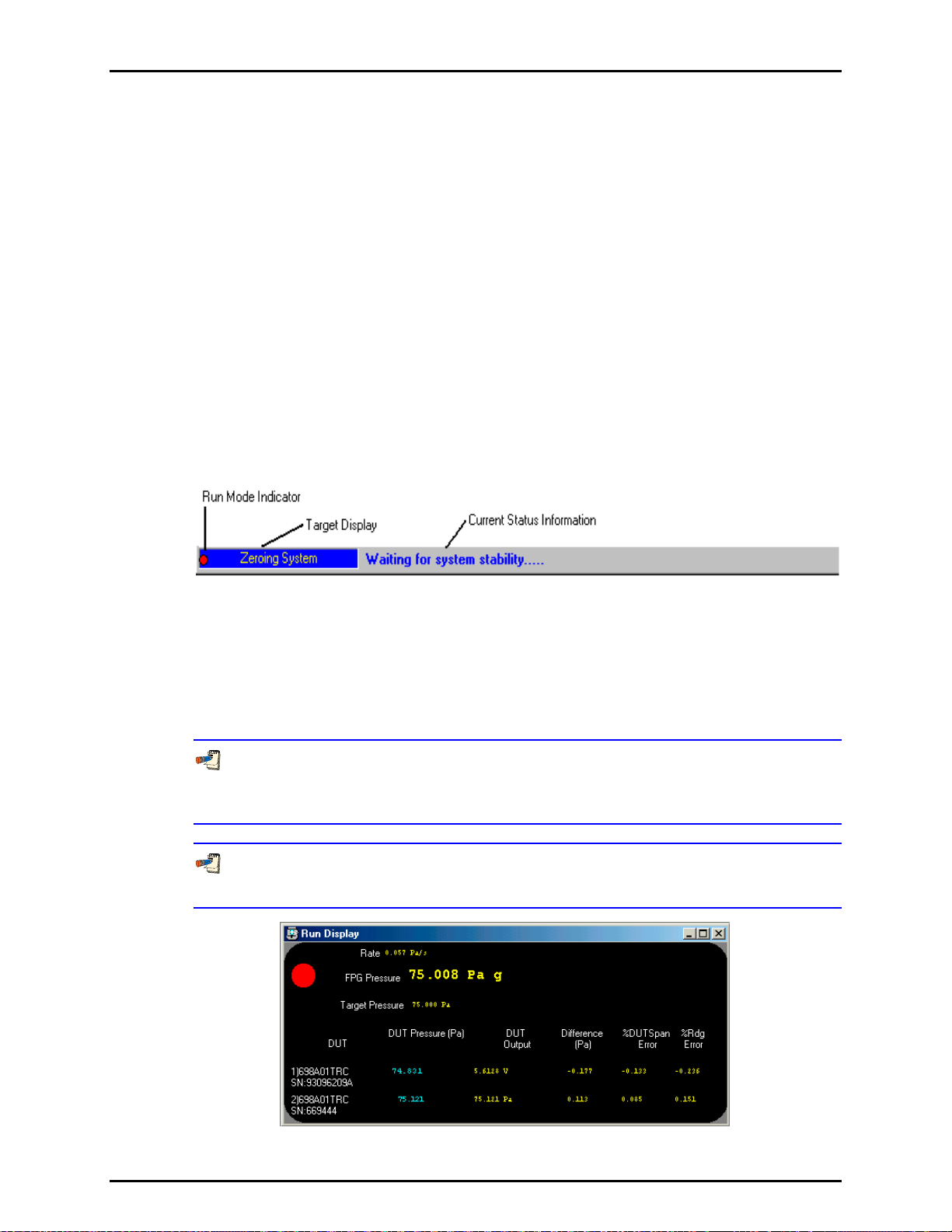
6. FPG TOOLS
6.3.1 STATUS BAR
The status bar located at the bottom of the main screen provides useful run-time information.
This status bar has three distinct sections: run mode indicator, target action, and
current action. The run mode indicator is a small blinking circle on the extreme left of the
status bar. When this indicator is visible, FPG Tools is polling all support devices and
updating the calculated FPG pressure. Each FPG remote operation changes the color and/or
shape of this indicator. If for any reason the interface with the FPG is interrupted, the
changes in state of this indicator will dramatically slow down. Changes will only occur at the
8s time out intervals used by the FPG. When the FPG pressure is very stable, it is difficult to
determine if the system is operating properly without this indicator.
The current target action displays on the inset panel on the left side of the status bar.
Common target actions include: zeroing, internal calibration, setting pressure, dwell
and averaging. In the case that a re-zero criterion is exceeded a special required target will
display in this field (see Section 6.6.4). This means the FPG must be re-zeroed in order to
obtain a re
Current actions appear in the middle of the status bar. For a typical target action, there are
several current actions that display to update the status of the target action. Each message
is provided to inform the user of the current step in the target process.
ady indication.
Figure 16. <Status Bar>
6.3.2 RUN DISPLAY
The <Run Display> screen is the main visual user interface to the FPG. The FPG Pressure,
ready indication, DUT pressures, DUT outputs and errors are available real time on this
display. When simple pressure monitoring is selected, maximizing this display is
recommended. This provides a large view of all of the pertinent outputs of the FPG.
Pressure is ready when there are no out of range errors in the system status and the
FPG pressure is within the stability setting or hold limit, based on whether or not VLPC is
actively controlling.
Double click the <Rate> and/or <FPG Pressure> fields to display a strip chart of the
corresponding indicator.
Figure 17. <Run Display>
Page 47 © 2007 DH Instruments, a Fluke Company
Page 60

FPG8601™/VLPC™ OPERATION AND MAINTENANCE MANUAL
A functional description of all display fields of the <Run Display> are included in the
following table.
Table 5. <Run Display> Labels
LABEL DESCRIPTION
Ready Indicator
Red/Green circular
indicator
FPG Pressure The calculated instantaneous pressure of the FPG in the last selected pressure unit. If “---
Target Pressure The current VLPC target pressure. If the VLPC is disabled or is not controlling pressure,
DUT Pressure The calculated pressure based on the DUT pressure to output range setup (see Section
DUT Output The direct output each active DUT formatted using the <Output resolutio n> specified in
%FS Error The difference between the DUT and reference divided by the full scale value of the DUT
%Reading Error The difference between the DUT and reference divided by the reference times 100.
A green light will display in this field when the FPG is Ready. This means that no status or
limit related errors are present (see Section 6.3.7) and that the rate of change of FPG
essure is within the stability criterion when the VLPC is not actively controlling the FPG
pr
pressure. If the VLPC is controlling, the stability criterion is ignored, the hold limit is used
as the final criterion for ready (see Section 3.6). If any of these criterion are not met, the
indicator w
-“ appears in this display, the FPG pressure is not valid or not currently available. After
the pressure and unit are a sequence of text tags to indicate the current operational state
these tags are listed below:
a – The FPG is in absolute measurement mode.
ad – The FPG is in absolute differential measurement mode.
g – The FPG is in gauge measurement mode.
t – A thermal transpiration correction is being applied to the FPG pressure.
h – A head correction is being applied to the FPG pressure.
Rate The instantaneous FPG pressure rate of change per second in the last selected pressure
units.
“N/A” displays.
DUT The serial number of all active DUTs.
6.8) for all active DUTs. If no DUTs are enabled,
the DUT pressure to see a <Spy Window> that contains all of the commands and
responses issued to the DUT. This can be useful when troubleshooting.
the DUT Setup (see Section 6.6.2.3).
times 100.
ill be red which means the FPG is not ready.
dashes appear in this field. Double-click
© 2007 DH Instruments, a Fluke Company Page 48
Page 61

6. FPG TOOLS
6.3.3 TARE DISPLAY
The <Tare Display> always holds the last system zero information. All values in this display
are used in the determination of FPG pressure. This data is stored even after FPG Tools is
closed and when run mode is turned off. Realize that the stored information is not
always valid. Several outside influences that are not detectable by the software can render
the tare information invalid. It is best for a user to always re-zero the system prior to taking a
new set of FPG data.
The FPG should be re-zeroed using FPG Tools any time the unit is turned off, handled by
an operator, prior to a comparison with another device, or after changing measurement
modes. Failure to follow this procedure may result in invalid pressure data.
Figure 18. <Tare Display>
Table 6. <Tare Display> Labels
LABEL DESCRIPTION
Tare Mode
Lube Prs The lubrication pressure in kPa at the time of tare.
Post Temp The mounting post temperature at the time of the last system zero.
Lube Temp The lubrication volume temperature at the time of the last system zero. This value is used
%RH The lubricating volume humidity at the time of the last tare.
This is the pressure measurement mode that was in effect when the system was last
zeroed. The field is useful when the operation of the FPG will include changes in
measurement mode.
N The load cell output in counts just prior to setting the value to 0. After the FPG has been
successfully tared in the active measurement mode, this value indicates zero drift since
the last tare.
ATM The atmospheric pressure at the time of the last tare.
for reference purposes only and is not applied to any calculations.
Page 49 © 2007 DH Instruments, a Fluke Company
Page 62

FPG8601™/VLPC™ OPERATION AND MAINTENANCE MANUAL
6.3.4 PLOT DISPLAY
FPG Tools can be used to generate plots with data taken during [Run w/Point Log] and
[Run Test Sequence] run modes. When point logging is enabled, use the [Plots] menu
option to select a common plot based on the data points logged in the data grid
(see Section 6.3.5). The <
to access new plots. As with any plot, at least two data points must be taken before a graph
will appear on the plot display. All plots include axis labels and a plot header to describe the
information used in generating the data plot. Press the [Print] toolbar icon to print the plot.
As with the other run displays, the <Plot Data> window can be scaled and positioned
as desired. Use the [Custom Plot] menu selection to plot data based on the available X and
Y columns of data in the active test data file. Menu choices below the [Custom Plots] menu
choice are used to create strip charts (see Section 6.3.4.1).
Use the <
Plot Files> drop down list box to select the DUT data to plot. When multiple DUTs
are used, an <All Plots> option is available to view data from all active DUTs. This option
only displays data from one test cycle at a time. As a result, a multiple cycle test sequence
will only display data from the active test cycle. Conversely, when a single DUT is selected,
all test cycles display for the selected DUT. When [Run w/Point Log] is active, there is only
one test cycle so all data is displayed for each DUT selected.
Plot Data> window also has a plot menu option that can be used
Figure 19. <Plot Data>
6.3.4.1 CUSTOM PLOTS
The plot menu and toolbar options contain a [Custom Plots] menu selection.
This selection presents the <Custom Plot Properties> setup window. The top
of the display contains a list of currently available custom plots. Double click any
plot or select the plot then press the [Plot Selection] button to exit the window
and plot the selected data. The bottom of the display allows custom plots to be
edited, created and removed.
Figure 20 shows the <C
available on the display. Editing custom plots follows the same basic editing
rules as all the <Test Sequence Editor> (see Section 6.6.5). The toolbar
s always act on the currently selected custom plot. Edit plots by typing in
option
any field. A flashing message displays to indicate that editing has begun.
You must press the [New] toolbar option to create a new custom plot.
© 2007 DH Instruments, a Fluke Company Page 50
ustom Plot> display. Table 7 explains the features
Page 63

6. FPG TOOLS
Figure 20. <Custom Plot Properties>
Table 7. <Custom Plot Properties> Tab Fields
FEATURES DESCRIPTION
Plot Selection
(button)
Description
(text entry)
X Axis Data
(list box)
Y Axis Data
(list box)
Press this button to plot the currently selected custom plot. Double clicking a
custom plot in the list has the same effect.
Plot
Enter text that describes the data that will be plotted. The text entered will
appear in the list of custom plots and at the top of plots generated using this
plot selection.
Select the data that will display along the X axis. The text of the selection
followed by units (when appropriate) will appear along the bottom of the plot.
Press the button next to the drop down list to change the text to associated
with <X Axis Data>. The exact text as entered will appear on the X axis of
the plot
Select the data that will display along the Y axis. The text of the selection
followed by units (when appropriate) will appear along the vertical axis of the
plot. Press the button next to the drop down list to change the text to
associated with <Y Axis Data>.
6.3.4.2 STRIP CHARTS
The FPG pressure and pressure rate can be updated on strip charts. Strip charts
can be created without taking data by using the menu choices below the
[Custom Plot] choice. Alternatively, double click the <FPG Pressure> or
<Rate> fields on the <Run Display> to begin a strip chart. Strip charts display
the most recent 200 updates of the FPG pressure values until 500 points have
been taken. At this point, the strip chart is reset and continues updating starting
with point number 1. Close the strip chart window to disable the strip chart function.
Strip charts are useful when trying to determine the stability of the FPG pressure.
In some calibration scenarios, a needle valve must be used to compensate for
the FPGs lubrication flow. In these situations, a user must isolate the DUT and
adjust the needle valve so that the FPG pressure rate is effectively 0 prior to
exposing the FPG to the instrument. A simple way to determine the effective rate
is to look at a strip chart of the FPG pressure rate. If the rate is oscillating about
0 for 200 samples, it is fare to say that the rate is effectively 0.
Page 51 © 2007 DH Instruments, a Fluke Company
Page 64
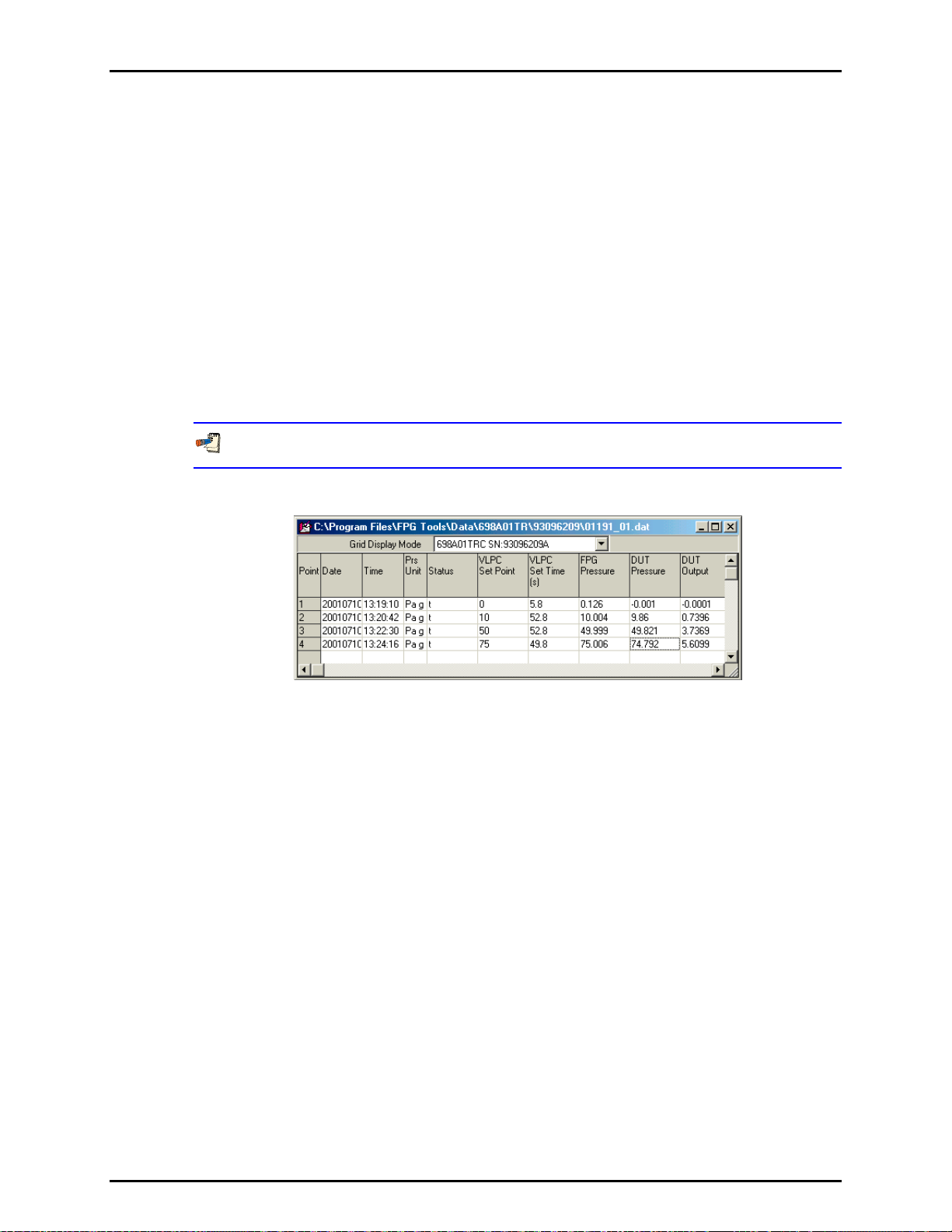
FPG8601™/VLPC™ OPERATION AND MAINTENANCE MANUAL
6.3.5 LOGGED DATA
When [Run w/Point Log] or [Run Test Sequence] is used as the run option, data points can
be logged to a user selectable data file and the logged data display. This display stores all
relevant data regarding each point taken by the user. Each point represents a snap shot of
all data found on the <Run Diagnostics>, <Run Display> and <Tare Values>. The title bar
contains the file name of the data file used to store the test data. Other than the data file
header, all test point information is logged to the data file in the same basic format as the
data display. Refer to the calculation section of this manual for more information on the data
logged on this grid. When [Run] [Run Monitor] is used, no data points will appear in this
data grid and FPG Tools disables all options relevant to taking a data point.
The data file name defaults to the year, Julian day and run of the day in the format
“YYDDD-R.dat”. The third data file run on January 10, 2001 would use the default file name
“01010-3.dat”. To change the file name, edit the file name field of the file box that displays
during initialization (see Section 9.2).
Use Table 8 as a key to help determine column information found in the data file.
Figure 21. <Logged Points> Display
© 2007 DH Instruments, a Fluke Company Page 52
Page 65

6. FPG TOOLS
Table 8. <Logged Points> Labels
LABEL DESCRIPTION
Grid Display Mode The model and serial number of all active DUTs display in this list box. When a
Point The number of the current data point.
Time/Date Time and date of the current point. The time is formatted as a 24 hour value,
Pressure Units The selected pressure units and measurement mode at the time the point was
Status This value contains any error status information present at the time the point is
selection is made, the grid is updated with data from the selected DUT.
“hh:mm:ss”. The date format is year, month, day: “YYYYmmdd”.
taken. This value will change with any new [Units] menu selection available.
After the pressure unit are a sequence of text tags to indicate the current
operational state these tags are listed below:
a – The FPG is in absolute measurement mode.
ad – The FPG is in absolute differential measurement mode.
g – The FPG is in gauge measurement mode.
t – A thermal transpiration correction is being applied to the FPG pressure.
h – A head correction is being applied to the FPG pressure.
logged (see Section 6.3.7). Points that are averaged contain an accumulation of
ividual error codes that occur over the course of the averaging cycle. This
all ind
information can be used to troubleshoot aberrant points.
Pressure is ready when there are no out of range errors in the system status
and the FPG pressure is within the stability setting or hold limit, based on
whether or not VLPC is actively controlling.
VLPC Target Pressure The last set target pressure when the VLPC is in use. If a pressure target was not
set, the field displays “N/A”
Set Time The time to reach stability after the last VLPC target pressure was set. If a point is
taken prior to reaching stability or the VLPC is not actively controlling, the field
displays “N/A”.
FPG Pressure The calculated FPG pressure in the pressure units listed in the <Pressure Units>
column. For averaged data points, the averaged FPG pressure is logged.
DUT Pressure The calculated DUT pressure in the pressure units listed in the <Pressure Units>
column.
DUT Output The output of the DUT in the output units set up in the DUT configuration (see Section
6.6.2.3).
DUT Difference The difference between the DUT pressure and the FPG pressure in the pressure
units listed in the <Pressure Units> column. When a DUT is not enabled, “----“
displays in this field.
DUT %FS Error The difference between the DUT and reference divided by the full scale value of
the DUT times 100.
%Reading Error The difference between the DUT and reference divided by the reference times
100.
FPG Min Pressure The minimum FPG pressure logged as the result of an averaging cycle (see
Section 6.4.2). The value can be used to quantify
control noise over the course of
an averaging cycle. For non averaged points, the instantaneous FPG pressure is
logged. In this case the value logged is the same as the <FPG Pressure> field.
FPG Max Pressure The maximum FPG pressure logged as the result of an averaging cycle (see
Section 6.4.2). The value can be used to quantify
control noise over the course of
an averaging cycle. For non averaged points, the instantaneous FPG pressure is
logged. In this case the value logged is the same as the <FPG Pressure> field.
STD FPG Pressure The standard deviation of the FPG pressure in the current pressure units over the
course of an averaging cycle (see Section 6.4.2). The value can be used to
y control noise over the course of an averaging cycle. For non averaged
quantif
points, “N/A” displays.
Tare Mode The measurement mode used for the system zero that was in effect when the
point was taken: g or a for gauge and absolute respectively.
The direct load cell output in counts.
Ν
Page 53 © 2007 DH Instruments, a Fluke Company
Page 66

FPG8601™/VLPC™ OPERATION AND MAINTENANCE MANUAL
LABEL DESCRIPTION
Correction factor due to the change in lubrication pressure since the last system
δΝ1
zero (see Section 2.7.1). The value represents the change of buoyancy force on
the load cell.
Correction factor due to the relative change in lubrication pressure and reference
δΝ2
pressure since the last system zero. The value represents the change in drag
force on the piston (see Section 2.7.2).
Correction factor due to the change in the reference pressure (atmosphere or
δΝ3
vacuum) after the last system zero. The value represents the change in buoyancy
force due to the reference pressure (see Section 2.7.3).
Head Correction Pressure error associated with the difference between the reference level of the
K_Cal Calibration factor in effect when the point was taken. This value will change if an
Effective Area Effective FPG area based on the current temperature (see Section 11.3).
Residual Pressure Instantaneous or averaged residual pressure in Pa as output by the vacuum
ATM Pressure Instantaneous or averaged atmospheric pressure in kPa.
ATM (0) Pressure Atmospheric pressure logged during the last tare. Same as the value found on
Lube Pressure Instantaneous or averaged lubrication pressure in kPa.
Lube (0) Pressure The lubrication pressure when the system was last zeroed. Same as the value
Post Temp Instantaneous or averaged mounting post temperature in °C. Each mounting post
Post Temp Rate/m The rate of change per minute of the mounting post temperature in °C/m.
Post Temperature (0) The mounting post temperature at the time the system was last zeroed. This
Lube Temp Instantaneous or averaged lubricating volume temperature in °C.
Lube Temp Rate/m The rate of change per minute of the lubricating volume temperature in °C/m.
Lube Temperature (0) The lubricating volume temperature at the time the system was last zeroed. This
%RH/m The rate of change per minute of the humidity measured in the lubricating volume.
%RH (0) The relative humidity logged at the time the system was last zeroed. This value
DUT and FPG. The value is automatically applied to the FPG pressure.
internal calibration is performed between points either discretely or as the result of a
tare (see Section 5.3).
reference sensor when it is enabled (see Section 6.6.2.1
0 Pa is always used. This value is only relevant when the FPG is being used in
absolute mode. Gauge mode reference pressure is ATM. Absolute differential
mode can display a value, but not apply it to the FPG pressure.
the <Tare Display> (see Section 6.3.3
zeroed between points.
found on the <Tare Display>. This value can change if the system is re-zeroed
between points.
temperature value is an average of both mounting post PRTs.
value can change if a re-zero occurs between points.
value can change if a re-zero occurs between points.
%RH Instantaneous or averaged relative humidity.
can change if a re-zero occurs between points.
). When it is not enabled,
). This value can change if the system is re-
6.3.6 VLPC CONTROL
This window is the interface to the VLPC. If the [Config], [System Setup], <Setup>,
<Enable VLPC> option is selected, the window is available for input in all run modes.
Use the tools on this display to: change range, vent pressure, abort control or set a new
target pressure. After each operation is executed, the window is disabled until the operation
© 2007 DH Instruments, a Fluke Company Page 54
is complete.
Use the <Operation Abort> toolbar function to abort operations that you do not want
to complete. However, this may leave the system in an undefined state. So make sure
that a new range is set or the pressure is vented if an early abort occurs.
Page 67
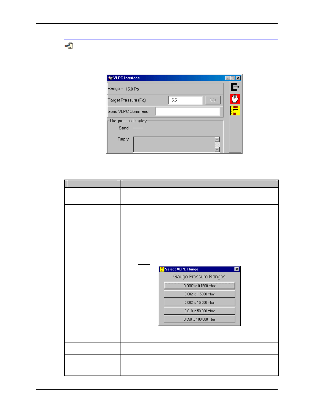
6. FPG TOOLS
Although the VLPC control window is available during the execution of a test sequence
(see Section 6.6.5), it is recommended that the controls not be used to prevent
corruption of the test sequence.
Figure 22. <VLPC Interface>
Table 9. <VLPC Interface> Options
LABEL DESCRIPTION
Vent
(Button)
Abort
(Button)
Range
(Button)
This function vents the system pressure and opens the bypass valve. The
FPG/VLPC and any DUT connected is left in a safe condition when this operation is
complete.
Aborts VLPC control. This means the VLPC will no longer dynamically control
system pressure. The last internal control point is left constant in the VLPC which
typically results in a stable FPG pressure.
When activated, a popup window allows the selection of the desired pressure range.
All pressure range values are listed in the current pressure display unit as the
approximate lowest controllable point for that range to the range full scale value.
Click the button that represents the desired pressure range. The current pressure is
vented, then the new pressure range will be set automatically. The process takes
about 30s depending on the current state of the system. The default hold limit
specified for the selected range is automatically set when the range change is
complete. Default hold limits are specified using the [Internal Limits] option (see
Section 6.6.4.7
).
Figure 23. <Select VLPC Range>
Range
(Label)
Target Pressure
(Entry Field)
Page 55 © 2007 DH Instruments, a Fluke Company
Displays the last set range of the VLPC.
Enter the desired target pressure in the displayed units then press the [Enter] key
or the [Go] button to set the pressure. The value displayed in this field always
represents the current target pressure when the VLPC is actively controlling
pressure. A “D” in the status indicator always notes VLPC control.
Page 68
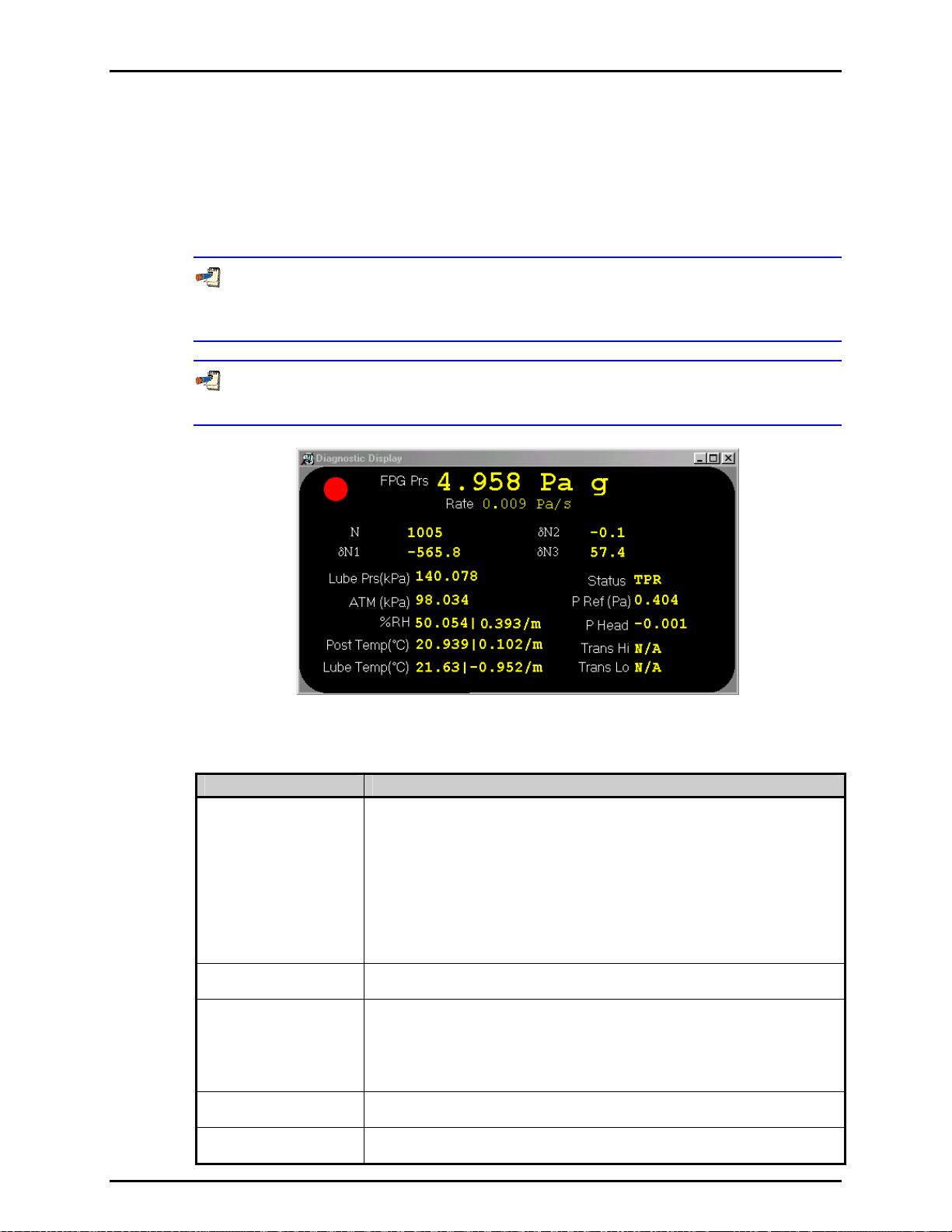
FPG8601™/VLPC™ OPERATION AND MAINTENANCE MANUAL
6.3.7 RUN DIAGNOSTICS
When FPG Tools is in run mode, all information on this display is continually updated.
The goal of this run screen is to provide a compact view of all discrete outputs used in
calculating the FPG pressure as well as the main calculation components. Table 10 lists
cific information on the
spe
Pressure is ready when there are no out of range errors in the system status and the
FPG pressure is within the stability setting or hold limit, based on whether or not VLPC is
actively controlling.
Double click the <Rate> and/or <FPG Pressure> fields to display a strip chart of the
corresponding indicator.
<Diagnostics Display> screen labels.
Figure 24. <Diagnostics Display>
Table 10. <Diagnostics Display> Options
LABEL DESCRIPTION
FPG Prs The calculated FPG pressure in the currently selected display units. When FPG
Ready Indicator
Red/Green circular
indicator
DUT Pressure The calculated DUT pressure based on the DUT pressure to output range setup
DUT Output The direct output of the DUT formatted based on the <Leading characters to
Tools is in a run mode, this field is updated every time a relevant calculation value is
updated. Use the [Units] menu to change the display units and/or measurement
mode. After the pressure and unit are a sequence of text tags to indicate the
current operational state these tags are listed below:
a – The FPG is in absolute measurement mode.
ad – The FPG is in absolute differential measurement mode.
g – The FPG is in gauge measurement mode.
t – A thermal transpiration correction is being applied to the FPG pressure.
h – A head correction is being applied to the FPG pressure.
Rate The instantaneous FPG pressure rate of change per second in the last selected
pressure units.
A green light will display in this field when the FPG is Ready. This means that no
status or limit related errors are present and that the rate of change of FPG pressure
is within the stability criterion when the VLPC is not actively controlling the FPG
pressure. If the VLPC is controlling, the stability criterion is ignored, the hold limit is
used as the final criterion for ready (see Section 3.6). If any ready criterion is not
met, the indicator w
(see Section 6.6.2.3). If the DUT is not enabled, dashes appear in this field.
strip> and the <Output resolution> specified in the DUT Setup.
ill be red which means the FPG is not ready.
© 2007 DH Instruments, a Fluke Company Page 56
Page 69
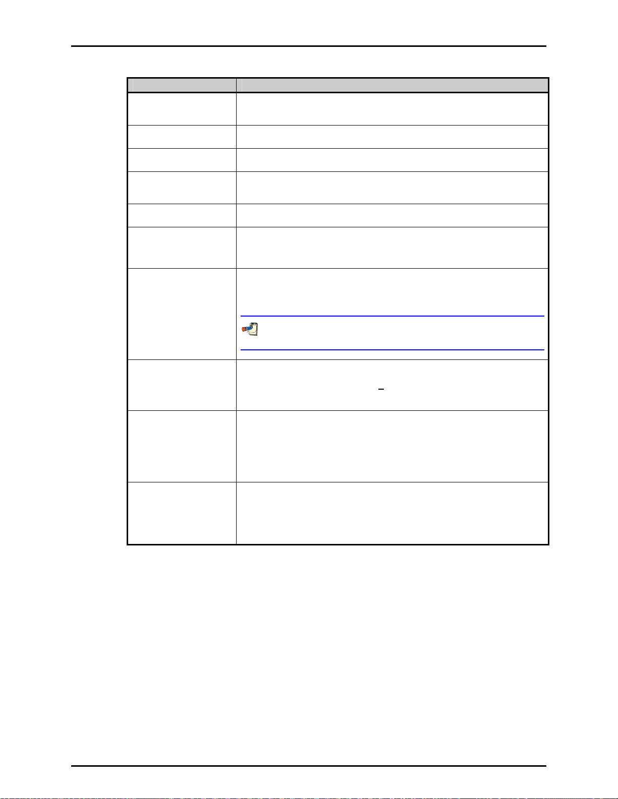
6. FPG TOOLS
LABEL DESCRIPTION
Ν
Load cell output in counts (mg). When the load cell is unstable, a red dot will
appear next to this display and a B will be logged in the <Status> field. Note that
the load cell is automatically zeroed when the FPG is turned on.
δΝ1
Correction factor due to the change in lubrication pressure since the last system
zero (see Section 2.7.1).
δΝ2
Correction factor due to the relative change in lubrication pressure and reference
pressure since the last system zero (see Section 2.7.2).
δΝ3
Correction factor due to the change in the reference pressure (atmosphere) after the
last system zero (see Section 2.7.3). In absolute mode, this value is zero provided
the last zero
Lubrication Pressure The lubrication pressure in kPa as read by the internal transducer. This value is
updated approximately every 1s to re-calculate the <FPG Prs>.
ATM The atmospheric pressure as read by the FPG internal transducer. Internal valves
are switched to read this pressure based on the <Lubrication Switch Time> value
(see Section 6.6.4). The pressure is updated in gauge mode only and when the
[A
TM] toolbar function is used.
Reference Pressure This output is provided in gauge to absolute mode transition only. During the
transition, the internal transducer is switched to read the pressure in the reference
port to make sure the reference vacuum is activated. The output of the transducer
during this transition displays in this field.
was also in absolute mode.
Do not confuse this pressure with the vacuum reference pressure read by the
vacuum reference sensor.
P Ref The pressure output by the vacuum reference sensor. This value is updated
approximately every 1s when the residual vacuum is active. This value can
activated or deactivated by using a [C
Section 6.6.2.1). The reference pressure is used
onfig],[System Setup],[Setup] option (see
in absolute mode operation only
(see Section 2.5). When no residual pressure device is set up the field displays “----“.
Post Temp The average temperature of the mounting post PRTs in °C. When the difference
between the current temperature and the tare value becomes larger than the
temperature re-zero limit, the FPG must be re-zeroed before a “Ready” indication
can be achieved (see Section 6.6.4.3).
The second field
in this display represents the average temperature rate of change
over the last minute. If this rate exceeds the rate of change limit, a re- zero warning
will display on the status bar and the FPG will indicate a “Not Ready” condition.
Lube Temp The temperature measured by the lubricating volume PRT in °C. If the difference
between this temperature reading and the reading of the <Post Temp> differ more
than the re-zero limit, the FPG must be re-zeroed (see Section 6.6.4.3).
The second field
in this display represents the average temperature rate of change
over the last minute. If this rate exceeds the rate of change limit, a re- zero warning
will display on the status bar and the FPG will indicate a “Not Ready” condition.
Page 57 © 2007 DH Instruments, a Fluke Company
Page 70
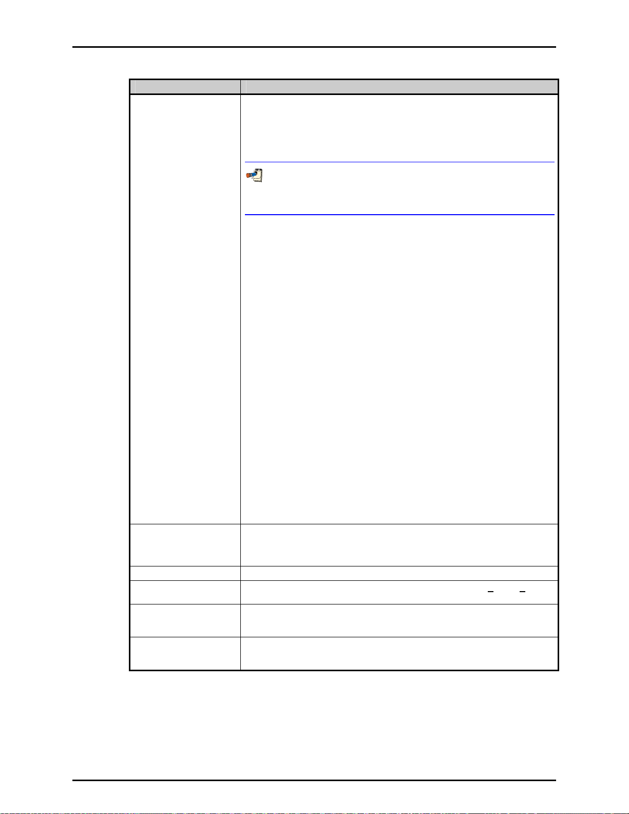
FPG8601™/VLPC™ OPERATION AND MAINTENANCE MANUAL
LABEL DESCRIPTION
Status The status of the current point. The field can be considered an exploded view of the
ready/not ready indication of the FPG. Do not confuse this label with the status bar
found at the bottom of the main program window. This text field may contain a
combination status information codes that indicate one or more internal limits have
been exceeded. In most cases, zeroing the FPG will remedy the problem. With the
exception of “R”, any status code forces a “Not Ready” condition in the FPG.
Any value present in the status field with the exception of “R”, forces
a “Not Ready” condition in the FPG ready indicator. In most cases,
re-zeroing the FPG is all that is required to remedy the problem.
A – The ATM pressure exceeds the stability limit or the value is invalid. When an A
appears, the FPG pressure is not updated regardless of the output of the load cell
and other FPG sensors. Use the <ATM> toolbar function to force the reading of
atmosphere.
L – The lubrication pressure exceeds the stability limit. This should only be a
momentary indication. If it persists, there may be a leak the system or the supply
pressure to the regulator could be running low.
B – The load cell has an unstable output or has an invalid reading. This is also
indicated by a red dot next to the <N> value on the <Diagnostics Display>. Since
this value represents noise levels beyond the resolution of the FPG, this indicator
does not cause a “Not Ready” condition when present.
T – The mounting post or lubricating volume temperatures have changed beyond
the tare limit (see Section 6.6.4.3), the relative difference between the mounting
post and lubricat
rate of change of any temperature indicator exceeds the re-zero limit. The system
should always be re-zeroed if this occurs.
t – At least one active DUT is out of tolerance relative to the FPG (see Section 6.8.2.4).
R – Indicates the F
criterion or other status indicators (see Section 3.6).
H - The humidit
change of humidity exceeds the specified humidity rate (see Section 6.6.4.4).
E - An error e
Calculation errors occur when some of the variables used in calculating the FPG
pressure contain values that generate a math error. When this occurs, no final FPG
pressure value is calculated.
I – One or more of the FPG calculation components is invalid. When this occurs,
the FPG pressure is not calculated.
P – The lubrication pressure has changed from it’s zero value more than the re-tare
limit. The system should be re-zeroed when this occurs.
Status
(continued)
V - The FPG is in absolute mode and the vacuum reference pressure is unstable.
This indication should be momentary. If it persists, there may be a leak on the
reference port, or the vacuum reference stability criterion is too restrictive (see
Section 6.6.4.2).
%RH Instantaneous lubricating volume humidity.
P Head The effective head correction in the active FPG pressure unit. Use [Config],[Settings]
to change the head height value (see Section 6.6.1).
Hi Trans
P(DUT)/P(FPG)
Thermal transpiration correction ratio based on the absolute pressure in the upper
chamber of the FPG. The ratio is the effective DUT pressure divided by the
absolute FPG pressure in the upper mounting post.
Lo Trans
P(DUT)/P(FPG)
Thermal transpiration correction ratio based on the absolute pressure in the lower
chamber of the FPG. The ratio is the effective low side DUT pressure divided by the
absolute FPG pressure in the lower mounting post.
ing volume temperatures differ beyond the acceptable limit, or the
PG pressure is not ready based on the current stability and hold
y value has changed beyond the humidity tare limit or the rate of
xists in the FPG calculation or output of one of its internal sensors.
© 2007 DH Instruments, a Fluke Company Page 58
Page 71
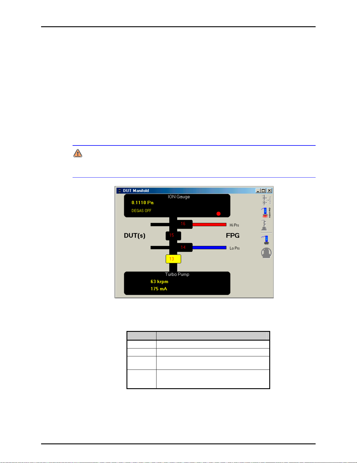
6. FPG TOOLS
6.3.8 DUT MANIFOLD
When the optional DUT manifold is active in the system setup, the <DUT Manifold> display
is available to monitor and control the devices connected to the manifold. When the vacuum
pump and ion gauge are active, their outputs display at the top and bottom of the form.
Activate the manifold and associated devices by using the [Config], [System Setup],
[Options] see Section 6.6.2.2. When a device is activated, it is available for use by FPG
Tools. It does not mean that the device is automatically turned on. Use the manifold toolbar
to control the vacuum pump and ion gauge as need.
The manifold display also acts as a pressure schematic. Based on the state of the valves on
the manifold display, the colors of the connecting tubes will change to reflect the
current pressure. Table 11 lists the colors and their correspondence to pressure.
ble-click any valve to toggle the current activation state.
Dou
Do not toggle valves on the DUT manifold without considering the impact the changed
state may have. In some cases, a large pressure differential may exist. This can damage
any device pneumatically connected to the manifold, including the FPG.
Figure 25. Window Display Toolbar
Table 11. <DUT Manifold> Color Scheme
COLOR DESCRIPTION
Red Pressure from the upper chamber of the FPG.
Blue Pressure from the lower chamber of the FPG.
Black Vacuum pressure generated by the manifold
vacuum pump.
Gray The current pressure state is undefined. This
typically occurs when valves are adjusted to
completely isolate the gas.
Page 59 © 2007 DH Instruments, a Fluke Company
Page 72
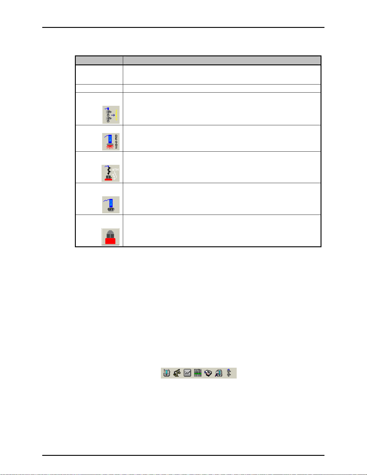
FPG8601™/VLPC™ OPERATION AND MAINTENANCE MANUAL
Table 12. <DUT Manifold> Display
LABEL DESCRIPTION
Ion Gauge The pressure and degas state of the ion gauge display in this field. The red/green
Turbo Pump The rotation speed and current of the manifold vacuum pump display in this field.
Zero DUT
Manifold
Degas Ion Gauge
Vent Vacuum
Pump
Turn On/Off Ion
Gauge
indicator is available when zeroing. This indicator is changed to green after the ion gauge
has successfully completed degassing.
Executes the manifold zero process (see Section 5.6). The manifold is isolated from the
FPG and subjected to a hard vacuum. This featu
that must be zeroed in low absolute conditions.
Toggles the state of the ion gauge degas option. When the ion gauge pressure is low
enough (approximately 6 MPa) degassing can be turned on. If the pressure is above this
limit, the ion gauge automatically turns off degassing. The ion gauge automatically turns
of degassing when the process is complete.
Vents the vacuum pump by opening the pump’s vent valve for 2s every 10s for 30s.
This prevents a large flow of air on the turbo pump. If the pump is spinning at high
speeds, a large rush of air can damage the pump over time.
Turns on or off the ion gauge. The manifold vacuum should be on and spinning at
approximately 63 krpm before attempting to turn the pump on. The ion gauge must be
active in the system setup and powered on for this option to be available.
re is intended to be used with devices
Turn On/Off
Vacuum Pump
Turns on or off the vacuum pump. It is best to vent the pump when it is turned off.
The turbine inside the vacuum pump will spin for several hours if not vented. The
manifold vacuum isolation valve (13) is not toggled when this option is used.
6.4 TOOLBARS
There are three main toolbars used by FPG Tools: the window display toolbar, valve control toolbar and
the function toolbar. The window display toolbar is used to display any of the various program
run screens. This is the smallest of the three toolbars and is available at all times. The other toolbars are
only available when FPG Tools is in a run mode (see Section 6.5). The valve control toolbar is available
only whe
n FPG Tools is executed in the Diagnostics user level (see Section 6.10).
6.4.1 WINDOW DISPLAY TOOLBAR
This toolbar is used to display any of the various FPG run screens. When a toolbar item is
selected, the corresponding run screen displays in the last stored position. This could be
outside the display area of the main program. As a result, it may be necessary to scroll the
main display to view the selected run screen.
Figure 26. Window Display Toolbar
© 2007 DH Instruments, a Fluke Company Page 60
Page 73

6. FPG TOOLS
Table 13. Window Display Toolbar Options
ICON DESCRIPTION
Activates the <Run Display> (see Section 6.3.2).
Activates the <Tare Display> (see Section 6.3).
Activates the <Plot Display> (see Section 6.3.4).
Activates the <Logged Points> window (see Section 6.3.5).
Activates the <VLPC Interface> window (see Section 6.3.6).
Activates the <Diagnostics Display> window (see Section 6.3.7).
Activates the <DUT Manifold> window (see Section 6.3.8).
6.4.2 FUNCTIONS TOOLBAR
The features on the Function Toolbar are enabled only when FPG Tools is in a run mode.
Then features specific to the current setup and run mode selected are enabled. For this
reason, some toolbar functions will not be available in some run modes. The following
sections detail the purpose and use of each of the available toolbar functions.
It is good practice to initiate only one function at a time. Due to timing factors with
other internal operations it may take several seconds before the selected function takes
place. Watch the <Status Bar> to monitor the state of the function when applicable.
Use the [Operation Abort] toolbar function to exit any functions that you do not wish to
complete.
Table 14. Functions Toolbar Option
ICON DESCRIPTION
[Move Back]
[Move Forward]
[Sequence
Pause]
[Take Point]
When a test sequence is the active run mode (see Section 6.5.4), this function returns the
test sequence co
pressed again, execution resumes with the target pressure of the previous test point.
Points are stepped back all the way to the beginning of the test sequence. The <Logged
Points> window highlights the row of the new point with each selection.
When a test sequence is the active run mode, this function allows repeated points to be
skipped. Repeatedly pressing this button automatically skips test execution to the next
previous logged point until an incomplete point is encountered. When the highest test
point logged in the test sequence is reached, the option is automatically disabled. The
<Logged Points> window highlights the row of the new point with each selection.
Use [Pause] to temporarily disable any automatic dwell or averaging time during a test
sequence. Press the button again to continue. This option is not available in any other
run mode. Pressure targets and data averaging are not affected by the pause state.
This feature is enabled only when the [Run w/Point log] option is in use. When pressed
all relevant instantaneous FPG and DUT calculation information is logged to the data file
and the <Logged Points> run screen (see Section 6.3.5). Use this function to take points
w
hen a test sequence is not desired. If a manual entry DUT is currently enabled, a
prompt to enter the DUT output will occur prior to logging the point. Make sure the DUT
output is entered in the configured DUT output units (see Section 6.8).
ntrol to the beginning of the most recent pressure target. If immediately
Page 61 © 2007 DH Instruments, a Fluke Company
Page 74

FPG8601™/VLPC™ OPERATION AND MAINTENANCE MANUAL
ICON DESCRIPTION
When first selected, [Auto Log] will be turned on. A prompt will appear allowing the entry
of a delay time in seconds. FPG Tools will automatically take a point every delay interval
seconds until this button is pressed again. This is identical to manually taking points
[Enable Auto
[Disable Auto
based on a specific time interval. Automatically logging points can be useful when
monitoring the effects of slowly evolving phenomenon or monitoring long-term system
Log]
stability and control.
Pay special attention to the status column of logged points when extremely
Log]
long automatic point logging is used. Changes in conditions may render the
FPG pressure invalid.
If a manual entry DUT is currently enabled, a prompt to enter the DUT’s
pressure will occur each time a point is logged. If this is not desired, disable
the DUT before enabling [Auto Log].
When selected, FPG Tools averages all logged data for the averaging time specified then
writes the results to the data file and the <Logged Points> run screen. If a manual entry
DUT is currently enabled, a prompt to enter the averaged DUT pressure will occur after
[Average Data]
[Plot Data]
[Zero System]
the averaging cycle is complete. The drop down arrow next to the main icon displays a
menu with the current averaging time and the option to enter a new averaging time.
By default the value is 5s but it can be changed to any value >=1 and <=1000.
Plots data currently logged in the data grid. The option is effectively a shortcut to the
[Plots] menu option. The toolbar function is not available in the [Run Monitor] run mode
(see Section 6.5.2). In this case, if data is present in the data grid the [Plo
should be used to generate new data plots.
Only one plot will display at a time in the plot display form. The plot can be scaled or
printed as desired (see Section 6.3.4). Any plot active at the time a point is logged is
automatically
updated with the information of the current point.
Use this option to zero (tare) the FPG. The load cell output is set to zero and the condition
of all sensors are logged to calculate correction factors (see Section 2.7). All zero information
display
s on the <Tare Display>. To zero the system, FPG Tools automatically attempts
to set the zero conditions based on the current measurement mode. When set, the zero
information is logged only after a successful stability check. Details on the procedure for
zeroing are described in Section 5.2
ts] menu option
To ensure that a valid zero is obtained, make sure any DUT connected to the
system does not connect the high and low reference ports of the FPG.
Use this option to check the zero of the FPG. FPG Tools sets the zero condition and
waits for stability in the FPG. Any zero error is indicated by the current pressure at this
time. With a few exceptions, all other program functions are disabled during the zero
[Zero Check]
check. Use the [Zero System] icon during the zero check to zero the FPG without again
waiting for stability. FPG Tools will remain in the zero check mode until the [Operation
Abort] icon is pressed.
Do not allow a zero check to continue more than 5 minutes in absolute mode.
The lubrication pressure will build up in the mounting post and eventually
reverse pressure the system.
In gauge mode, [Zero Check] and [Close Bypass Valve] have the same function. This
feature is intended for use in absolute mode.
© 2007 DH Instruments, a Fluke Company Page 62
Page 75

6. FPG TOOLS
ICON DESCRIPTION
Activates the internal calibration process that is used to correct the slope of the FPG by
comparing the current output of the load cell with the output of a known mass. The
relative error between the readings is used to determine a new calibration factor for the
[Internal
Calibration]
[Purge System]
[Read ATM]
[Open Bypass
Valve]
[Close the
Bypass Valve]
[Open Control
Reference]
[Close Control
Reference]
[Raise Internal
Calibration Mass]
FPG. Refer to Section 5.3 for details on the internal calibration process.
The
results of the internal calibration display with the option to: activate the new
calibration, log the calibration information to the calibration log file print the calibration or
simply to cancel.
An internal calibration must be executed every time the pressure measurement mode is
changed. Failure to do so will result in an FPG span error.
The internal calibration process can automatically be performed with each system zero
if the <Auto run internal calibration > option is selected (see Section 6.6.2.1).
Activates the purge sequence to hasten the process of obtaining stable conditions within
the lubricating volume. Purging is frequently required when changing measurement mode
and after initial FPG startup. The FPG lubricating volume is cycled in pressure a number
of times until the change in relative humidity inside the load cell reduces to a value within
the factory limit.
Press this button to force an atmospheric measurement. Internal valves are actuated to
expose the internal pressure transducer to atmosphere until a stable value is obtained.
The valves are then actuated to expose the transducer to the lubricating volume pressure
for normal operation. Error associated to typical changes in atmosphere are not
significant while error associated to changes in lubrication pressure can be significant (see
Section 2.7).
During
normal operation, atmosphere is refreshed when gauge mode is set and at
intervals based on the <ATM/Lube Switch Delay> (see Section 6.6.4.1), which is typically
set to about 15
minutes. As a result, the display of atmosphere on the <Diagnostics
Display> is not a real time update. If a faulty reading is ever made, the error would
persist for several minutes. Use this function to update the value.
Opens the FPG bypass valve. This function effectively, isolates the high and low ports of
the FPG. Before a manual pressure can be set, this feature must be used to allow a
differential pressure on the FPG piston-cylinder.
The icon on the toolbar does not represent the current state of the bypass valve.
Instead, the icon represents the action the function will carry out.
Closes the FPG bypass valve. Use this icon to manually return to a zero condition. In
absolute mode, the leak of lubrication pressure through the bypass to the reference port
induces a differential pressure. To view 0 differential pressure in absolute mode the
vacuum reference must also be shut off by deactivating valve 9 (see Section 5.2.1).
Activates the FPG control reference valve 11 (see Figure 13). When the VLPC is
activated, this fe
range. When zeroing the FPG, the valve is automatically closed for the duration of the
ature is disabled and control of the valve is based on the active VLPC
zero and opened if the valve was activated at the beginning of the zero.
Deactivates the FPG control reference valve 11. When the VLPC is activated, this feature
is disabled and control of the valve is based on the active VLPC range.
Removes the internal calibration mass from the measuring mechanism of the load cell.
The process takes approximately 10s. During this time, the FPG pressure is not valid.
This function is available in advanced user level only (see Section 6.10).
Page 63 © 2007 DH Instruments, a Fluke Company
Page 76

FPG8601™/VLPC™ OPERATION AND MAINTENANCE MANUAL
ICON DESCRIPTION
Lowers the internal calibration mass onto the measuring mechanism of the load cell.
The process takes approximately 10s. During this time, the FPG pressure is not valid.
When the mass is lowered, the load cell output will change by the weight of the internal
[Lower Internal
Mass]
[Shut Down FPG]
[Restart FPG]
[Abort Run
Mode]
[Operation Abort]
calibration mass. The calculated FPG pressure will also change accordingly. This is a
diagnostics tool only available in the advanced user level.
This function should be used to vent all lubrication pressure from the lubricating volume.
Without lubrication pressure, the piston cannot be sensitive, therefore the FPG is
effectively shut down. Use this function prior to disassembling the FPG. The icon image
will change after the function is selected.
Always shutdown the FPG when it will not be used for an extended amount of time.
This will help to avoid contaminants between the piston and cylinder.
Re-activate the FPG by setting the last used pressure measurement mode. The function
has the same effect as directly selecting a measurement mode. When the process is
complete, the lubricating volume is pressurized according to the measurement mode.
Abort is used to abort the active run mode and return to an idle state. The FPG pressure
is automatically vented and the bypass valve is opened as part of the abort process. Prior to
aborting, a message allows the abort to be canceled if the option was not selected intentionally.
When this function is selected during a test sequence, an option is available to resume
program control with the run monitor opposed to completely returning to an idle state.
The program control box close option X and the [Run], [Exit] option perform the same
function as the [Abort Run Mode] option when FPG Tools is in a run mode.
This feature is enabled only when potentially long program functions are in progress.
This includes: zeroing, changing measurement mode, running an internal calibration,
purging and reading atmosphere. When this option is selected, only the current operation
is aborted, FPG Tools will remain in the current run mode.
The option is best used when a function is started that the system will not be able to
complete due to a setup error. Abort the operation, complete the necessary setup, and
then retry.
Aborting internal calibrations can leave the FPG in a state in which the internal
calibration mass is lowered and the calibration is complete. FPG Tools makes every
attempt to avoid this condition, however, repeated aborts by the user may result in
this condition. To abort the internal calibration, press the [Operation Abort] option
one time only.
6.4.3 VALVE CONTROL
FPG Tools automatically performs all necessary valve changes based on the requirements of
the current pressure measurement mode and the requested operation. Normal system
operation does not require understanding or use of any of the FPG internal valves. For quick
steps in diagnosing problem, FPG Tools displays the state of the 16 supported valve drivers
in Factory Mode only. Valves 1 through 11 are used by the FPG on a regular basis.
Valves 13 to 16 are extra valves not needed in the general FPG/VLPC configuration. Refer
to Section 11.1 for information on the internal valves
any of the desired valves to toggle its actuation state. A depressed button means the valve is
actuated while the normal state means the valve is in it’s normal state. There is typically a
small delay between the time the valve option is selected and the time the valve actually
changes state. The valve toolbar display is refreshed with the state of the valve only after the
state change occurs.
During normal system operation, FPG Tools performs all of the necessary valve
operations based on the pressure measurement mode and requested operation.
The ability to change valve states is provided for diagnostics purposes only.
and their function. Click the number of
© 2007 DH Instruments, a Fluke Company Page 64
Page 77

6. FPG TOOLS
Changing valves manually can place the FPG in an unstable situation possibly causing a
system overpressure or forcing the lubrication pressure back into the lubricating volume.
Manual valve operation is provided for diagnostics purposes only and requires a thorough
understanding of the function of each valve in the system. Most invalid valve
configurations can be remedied by re-selecting the measurement mode.
Figure 27. Manual Valve Control Toolbar
6.5 [RUN]
The [Run] menu contains options related to monitoring the output of the FPG. Use these options to put
FPG Tools into a run mode. When FPG Tools is not in a run mode, the program is considered to be idle.
This means the state of the FPG and VLPC are not being monitored by the program. There are three
basic run modes: [Run Monitor], [Run w/Point Log], and [Run Test Sequence]. Before entering any
of the run modes for the first time, the system must be initialized to synchronize FPG Tools with the states
of the FPG and VLPC.
To abort any run mode use the toolbar <Abort> option or any of the main program exit options.
The premise of a run mode is to put FPG Tools in a state in which the PC software behaves like a
common stand alone instrument with multiple discrete function keys. Use any of the control toolbars to
set pressures, change displays, change pressure units and measurement mode, log points (if supported)
or repeat data points (if supported). Most program configuration options can also be changed while in a
run mode. It is possible to create and use a new DUT or disable an active DUT without ever exiting a run
mode. Run modes themselves can be selected at any time without aborting the active run mode.
Run modes do not need to be aborted prior to making configuration changes or selecting a new
run mode. However, it is recommended that configuration changes should not take place after a run
mode is selected that uses data acquisition. These changes will not be reflected in the data file.
The normal state of the FPG internal valves are set up to put the FPG into gauge mode with the system
properly lubricated when power is turned off. This is a safe condition that should occur immediately
following a power up. However, improper connections or pressure supplies can prevent this safe
condition. As a result, it is good practice to always leave FPG Tools in a run mode when the FPG is set up.
This is the only means of determining the conditions of the FPG.
6.5.1 RUN MODE INITIALIZATION
Before FPG Tools can monitor the output of the FPG, the software must be initialized to set
the system to a known state. The initialization process must occur one time at the beginning
of the transition from an idle state to any run mode. After a run mode is entered, transitions
to other run modes do not require another initialization. FPG Tools automatically initializes
the system when required. While initialization is in progress, the <Status Bar> will display
information specific to the current step in the initialization process.
Do not abort operations that take place as part of the initialization process. If the FPG
is not properly initialized, pressure will not be calculated.
Page 65 © 2007 DH Instruments, a Fluke Company
Page 78

FPG8601™/VLPC™ OPERATION AND MAINTENANCE MANUAL
Update the <Tare Display> with the last saved tare information for the FPG.
FPG pressure is calculated only after valid tare data is available.
Initialize the RS232 interface of the FPG. An RS232 cable must be connected to the
FPG COM1 port and an RS232 port on the host PC. The host PC port must be specified
using the <System Setup><Interface> option (see Section 6.6.2.2).
Initialize the remote interface of the VLPC if it is enabled in the system configuration
(see Section 6.6.2.1). An RS232 cable must connect the FPG COM2 port to the
COM1
port of the VLPC. There is no software setup required to specify port and
communications settings. When the VLPC is enabled and an interface error occurs,
the initialization process is aborted.
The current valve state, reference pressure and lubrication pressure are queried to
determine the active measurement mode. The mode that most resembles the valve and
pressure configuration within the FPG is then specifically set. When the mode is not fully
defined by the pressure and valve state, a prompt will occur to select the desired mode to
operate on.
Initialize the remote interface of the DUT if enabled in the <Current Configuration>.
The DUT must be connected to the host PC according to the DUT interface selections in
the [Config], [System Setup], <Interface> option (see Section 6.6.2.2).
Initialization is complete.
6.5.2 [RUN MONITOR]
[Run Monitor] automatically refreshes the output of the FPG and allows use of all discrete
controls provided by FPG Tools. There are no defined steps in this run mode. Use this run
mode to monitor the FPG like a standalone instrument when data acquisition is not
necessary. Of the three run modes, [Run Monitor] most closely resembles a simple
instrument interface. Use the control toolbar and the <VLPC Interface> window to set
pressure and change the state of the FPG see Sections 6.4.2 and 6.3.6.
6.5.3 [RUN W/POINT LOG]
This option is identical to the [Run Monitor] option with the added ability of data acquisition.
When the option is selected, a standard file selection dialog displays to allow the entry of the
name of the data file. A default data file name is automatically provided by FPG Tools (see
Section 9.2.1). Data points can be taken at any time by using the [T
Point] or [Auto Point] options (see Section 6.6.4.2). There is no time limit or specific
uence required with this option.
seq
All active configuration information available at the time [Run w/Point Log] is selected is
logged in the header of the data file. Changes made to any parameter logged in the header
is not reflected in the completed data file.
For best use of the data file, do not make changes to the program configuration after the
run mode begins. Most changes will not be reflected in the data file.
ake Point], [Average
6.5.4 [RUN TEST SEQUENCE]
[Run Test Sequence] is available only after one of the other run modes have been selected.
Use this option to execute a test sequence created with the <Test Sequence Editor> (see
Section 6.6.5). FPG Tools automatically sets each test pressure and averages the results
according to the test seq
sets [Run Monitor] mode and vents all system pressure. For this reason, test sequences
are a good way to safely run long, multi cycle tests overnight. The steps involved with
running a test sequence are described below.
© 2007 DH Instruments, a Fluke Company Page 66
uence. When all test cycles are complete, FPG Tools automatically
Page 79

6. FPG TOOLS
Select the data file name. FPG Tools provides a default data file name that can be edited
as desired (see Section 9.2.1).
Select the test sequence to execute.
If a pressure cycle is specified in the test sequence, the VLPC is set to a range that best
accommodates the pressures in the pressure cycle. The maximum then minimum
pressure cycle pressures are set for the number of pressure cycles specified.
This pressure cycle occurs only one time, at the beginning of the first test cycle.
A VLPC range is selected that allows the maximum test sequence pressure up to the first
range change in the test sequence or the end of the test, whichever comes first. The
hold and stability limits specified on the <Control> tab of the test sequence are set at
this point.
The test sequence begins stepping through the test points starting with the first test point
in the test sequence.
If the test point specifies a range change, FPG Tools detects the best range to use
for the test points between the current point and the end of the test, whichever
comes first. This optimum range is automatically set if it is not the active range.
The default hold limits are used whenever the VLPC pressure range is changed in
the middle of the test sequence.
If the test point specifies a tare, the system is automatically tared in the same fashion
as the [Zero System] toolbar function (see Section 5.2).
An internal calibration will be executed for every point that is zeroed when <Auto
run internal calibration while zeroing> is enabled (see Section 5.2).
The test pressure is automatically set using the VLPC when it is active. Otherwise, a
prompt is provided for the operator to manually set the test pressure. In this case, do
not press the <OK> button until the pressure has been set.
If the test point is a tare check point, the zero condition is set and the tare
stability test is used to wait for stability (see Section 5.2.2). The pressure is then
ed for the specified averaging time up to 15s then logs the data point. The
averag
test sequence resumes with the next test point, Step r.
FPG Tools waits for a ready condition or a stability timeout before moving on to the
next test step. The stability timeout counts down on the status bar during this
process.
The test dwell time counts down.
FPG Tools averages all data for the specified averaging time. DUT data is also
averaged when available. The results are logged in the data file and on the main
display.
Repeat Steps to for each step in the test sequence.
Repeat Steps to for each test cycle.
Page 67 © 2007 DH Instruments, a Fluke Company
Page 80

FPG8601™/VLPC™ OPERATION AND MAINTENANCE MANUAL
6.6 [CONFIG]
All changes to the setup of FPG Tools are managed by the options in the [Config] menu. The different
types of configuration changes are segregated into the categories: [Settings], [System Setup], [FPG
Calibration Setup], [Internal Limits], [Test Sequence Editor], [DUT Editor] and [DUT Definition].
Access to many of the configuration options can be limited by the [User Level] feature. The following
sections detail each configuration option.
6.6.1 [SETTINGS]
The [Settings] options are always enabled for use regardless of the current run mode or
user level. When any run mode with data acquisition is enabled, it is recommended that
these settings not be changed to avoid inconsistent results. The state of each parameter is
logged in the data file at the beginning of the run mode. Changes in the parameters may
have an impact on the data but will not be directly reflected in the data file.
Figure 28. <Settings>
Table 15. System Settings
LABEL DESCRIPTION
Pressure Head
(entry field)
Stability Setting
(%current range)
(entry field)
Hold Setting
(%current range)
(entry field)
FPG Pressure
display
resolution
(drop down list)
Use default
pressure
resolution
(check box)
The height difference in cm from the DUT to the reference level of the FPG. The FPG
(cm)
reference level is slightly above the center of the mounting post (see Section 2.6.1). The
convention is to use a negative h
and a positive height when the DUT is above the reference level. The calculated head
correction is logged for each point when a data acquisition run mode is active.
A rate of change of pressure per second limit used to determine a ready condition when
automatic VLPC pressure control is not active. If the rate of change of FPG pressure
exceeds this limit, the <Ready Indicator> on the <Run Display> is set to red for “Not
Ready”.
The value must be entered as a percentage of the current system range. The range is
typically the range of the VLPC when it is active. Otherwise, the range is 10 kPa.
A symmetrical positive and negative limit around the target pressure within which the
controlled pressure is to be maintained. If the controlled pressure deviates from this limit
the <Ready Indicator> is set to red for “Not Ready” (see Section 3.6).
The value must be entered as a
typically the range of the VLPC when it is active. Otherwise, the range is 10 kPa.
When the <Use default pressure resolution> option is not checked, this field determines
the number of digits to display in the FPG (and DUT) pressures. The formatting is applied
to the pressure in the currently selected pressure unit. New pressure unit selections will
have no bearing on the resolution displayed.
When this option is checked, FPG Tools uses default display resolution based on the
pressure unit selected. User defined units may not display an appropriate amount of
pressure resolution (see Section 6.9.1). In this case, uncheck the option and make and
approp
riate resolution selection.
eight value when the DUT is below the reference level
percentage of the current system range. The range is
© 2007 DH Instruments, a Fluke Company Page 68
Page 81
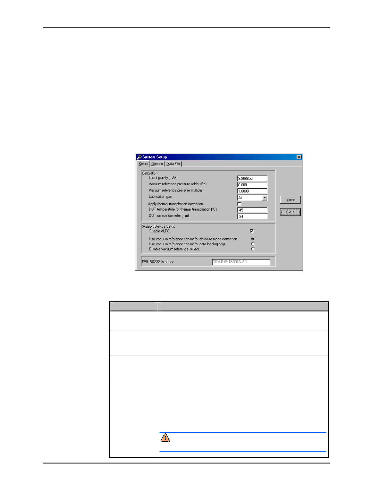
6. FPG TOOLS
6.6.2 [SYSTEM SETUP]
This option displays the system setup screen to allow several different types of
configuration changes. Click the folder with the label that represents the desired change then
make the necessary edits. When all changes are complete, press <Save> to activate the
changes and return to the main program. Press <Close> to ignore the changes and return to
the main program.
6.6.2.1 <SETUP>
The <Setup> folder defines how FPG Tools will interact with support system
devices, what automatic features are enabled and lists program constants that
effect overall system metrology. Special care should be taken to ensure that any
value entered is in the proper units with the correct sign.
Figure 29. <System Setup><Setup> Tab
Table 16. <System Setup><Setup> Options
LABEL DESCRIPTION
Local Gravity
(entry field)
Vacuum
Reference Adder
(entry field)
Vacuum
Reference
multiplier
(entry field)
Lubrication Gas
(drop down list)
The gravity determined at the test location of the FPG. This value is used
when determining the new calibration coefficient after an internal calibration
is performed (see Section 11.3.5.4).
The pressure adder in Pascal to apply to the output of the vacuum reference
device. The value is obtained by pulling vacuum with a turbo pump to
(Pa)
achieve a true zero. The output of the device under this condition is the
zero offset (see Section 8.3).
The pressure multiplier to apply to the output of the vacuum reference
device. The value is obtained by performing a calibration with the device
and the FPG.
This is the gas used to lubricate the FPG piston cylinder. Select the gas
that will be connected to the “Drive Air” port on the back of the FPG. The
gas must be known to properly determine changes in buoyancy on the
system.
“Air” is the recommended lubrication gas selection. Using Air prevents the
need to purge the system prior to use and avoids a gas mixture in the test
port of the FPG. If “N2” is selected, the FPG must be thoroughly purged of
all traces of Air.
Failure to properly purge when N2 is used can result in short
term pressure instability and faulty pressure measurements.
Page 69 © 2007 DH Instruments, a Fluke Company
Page 82

FPG8601™/VLPC™ OPERATION AND MAINTENANCE MANUAL
LABEL DESCRIPTION
Apply thermal
transpiration
correction
DUT temperature
for thermal
transpiration
correction
DUT orifice
diameter
Enable VLPC
(check box)
Vacuum
Reference
Options
(list box)
Check this box if the DUT requires a thermal transpiration correction. Refer
to the DUT instruction manual for details on whether or not the DUT
requires a transpiration correction. Thermal transpiration is an absolute
pressure measurement mode phenomenon that effects DUTs that are
heated significantly above ambient conditions for normal operation. The
effect becomes significant at 100 Pa and peaks at approximately 10 Pa.
See Section 11.3.4 for details on how the correction is applied. The value of
the correction rat
The steady state temperature of a DUT that requires a thermal transpiration
correction. This temperature is used to determine the DUTs thermal
transpiration correction when the correction is active.
The minimum connection tube diameter between the DUT and the
FPG8601. This value is typically a diameter internal to the DUT.
Check this box to use the VLPC to control the FPG pressure. When
checked the <VLPC Interface> display is enabled and available for use.
Uncheck this box to use a pressure controller independent of the FPG.
This option is automatically checked if a test sequence is selected that uses
automatic pressure control and is unchecked if the sequence uses manual
control.
This list box allows selection of the three modes of use of the FPG vacuum
reference sensor.
io displays real time on the <Run Diagnostics> display.
The output of the vacuum reference sensor is not useful in
gauge mode because ATM is significantly greater than the full
scale value of the sensor. Therefore, all vacuum reference
pressure options have no bearing on gauge mode operation.
Use vacuum reference sensor for absolute mode correction - This is
the most typical use of the sensor. In absolute mode testing, a vacuum
reference pressure device is required to define the absolute pressure from
the FPG calculated differential pressure (see Section 2.8). The device
FPG RS232
Settings
output displa
Display> during absolute mode operation.
Use vacuum reference sensor for data logging only - The output of the
vacuum reference sensor is logged in the FPG data file and displayed on
the <Diagnostics Displa y>. However, the value is not used to convert the
FPG differential pressure into an absolute pressure. This is the desired
selection for absolute differential mode operation. The vacuum reference
pressure can be used for thermal transpiration corrections and determining
vacuum stability while testing.
Disable vacuum reference sensor - Use this option when no vacuum
reference sensor will be used by FPG Tools. "0.0" is logged in the FPG
data file and displays on the <Diagnostics Display>. Using this feature in
absolute mode induces an error of several Pa depending on the vacuum
pump.
The COM port and RS232 settings of the FPG. This selection must be
selected and saved before FPG Tools can interface with the FPG. By
default the FPG will use the RS232 settings 19200, N,8,1. The serial port
used to connect the FPG is dependant on the PC used to run FPG Tools.
ys in the <Vacuum Reference Prs> field on the <Diagnostics
6.6.2.2 <OPTIONS>
The options tab allows selections related to automatic functions within FPG Tools
and the optional DUT manifold.
Table 17 describes the features on this tab.
© 2007 DH Instruments, a Fluke Company Page 70
Page 83
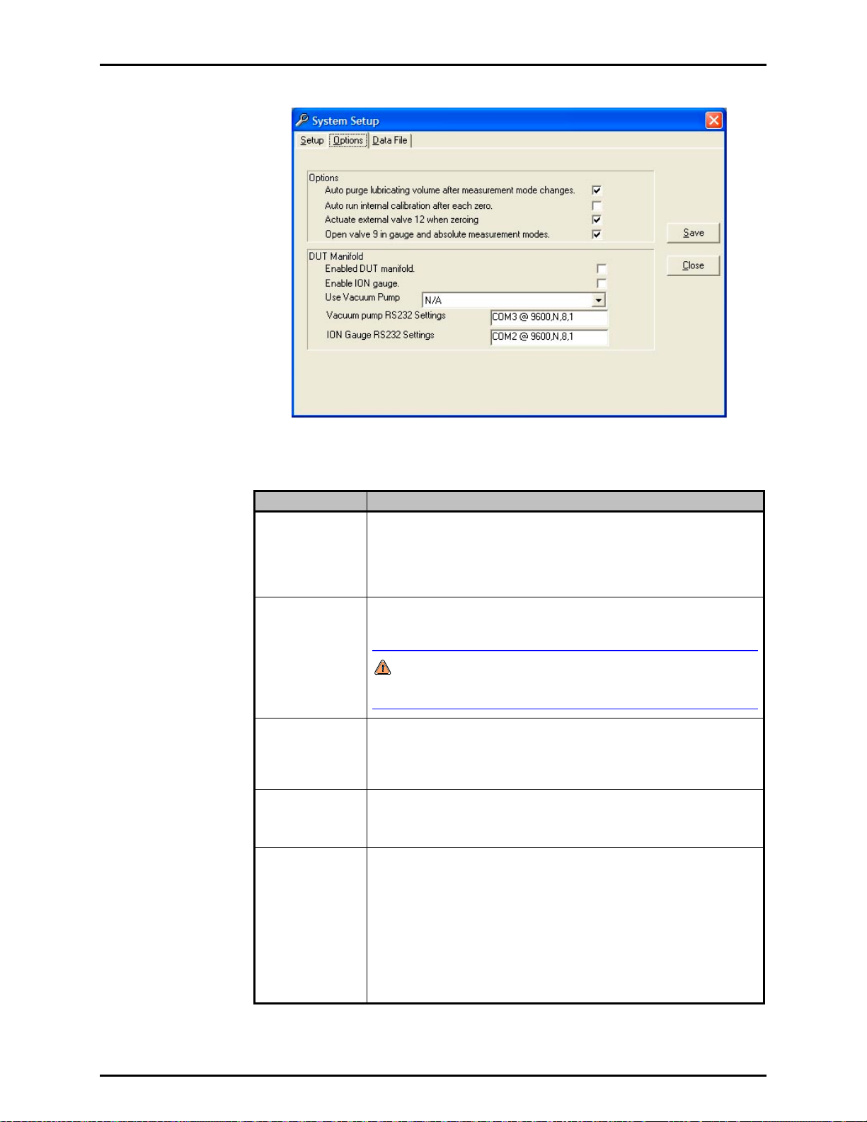
6. FPG TOOLS
Figure 30. <System Setup><Interface>
Table 17. <System Setup><Options> Options
LABEL DESCRIPTION
Auto purge
lubricating
volume after
measurement
mode changes
Check this item to automatically run a system purge when the pressure
measurement mode is changed. A warm up time and a system purge are
typically required after changing measurement modes to rapidly obtain the
proper humidity conditions around the load cell. This feature is functionally
equivalent to using the <Purge> toolbar function (see Section 6.4.2).
(check box)
Auto run internal
calibration after
each zeroing
(check box)
Check this feature to automatically run an internal calibration when the FPG
is zeroed. This feature should be checked to obtain the best accuracy for the
system as it allows for frequent and simultaneous span and zero correction.
An internal calibration must be executed every time the pressure
measurement mode is changed. Failure to do so will result in an FPG
span error.
Use external
valve 12 or
zeroing
(check box)
Check this box to deactivate external valve driver 12 on the FPG base (see
Section 11.1) prior to zeroing and when in gauge mode. The concept of
this option is to
allow the vacuum reference sensor to remain isolated from
atmosphere when it is not in use. Maintaining vacuum is a good way to
minimize zero drift.
Enable DUT
Manifold
When checked, FPG Tools automatically activates valves related to the
FPG manifold as needed when changing measurement modes, zeroing and
during other macro processes in FPG Tools. Do not check this option
unless the DUT manifold will be used with the FPG.
Enable Manifold
Vacuum Pump
Check this option to allow FPG Tools to interface with the manifold vacuum
pump. The pump must be powered on and connected to the system PC
according to the <Vacuum Pump RS232 Settings>. The pump vent valve
and remote switch must be installed on the vacuum pump for proper use.
FPG Tools will automatically change the state of the vacuum pump as need
by the current operation when the pump is activated. Use the tools on the
<DUT Manifold> (see Section 6.3.8) display to manually change the state
of the vacuum pu
mp.
The Varian 150 Dry Var turbo molecular pump, model 9699163 is the only
supported vacuum pump available for this option. Other Varian pumps may
also work with the FPG Tools as long as the commands are 100 % compatible.
Page 71 © 2007 DH Instruments, a Fluke Company
Page 84
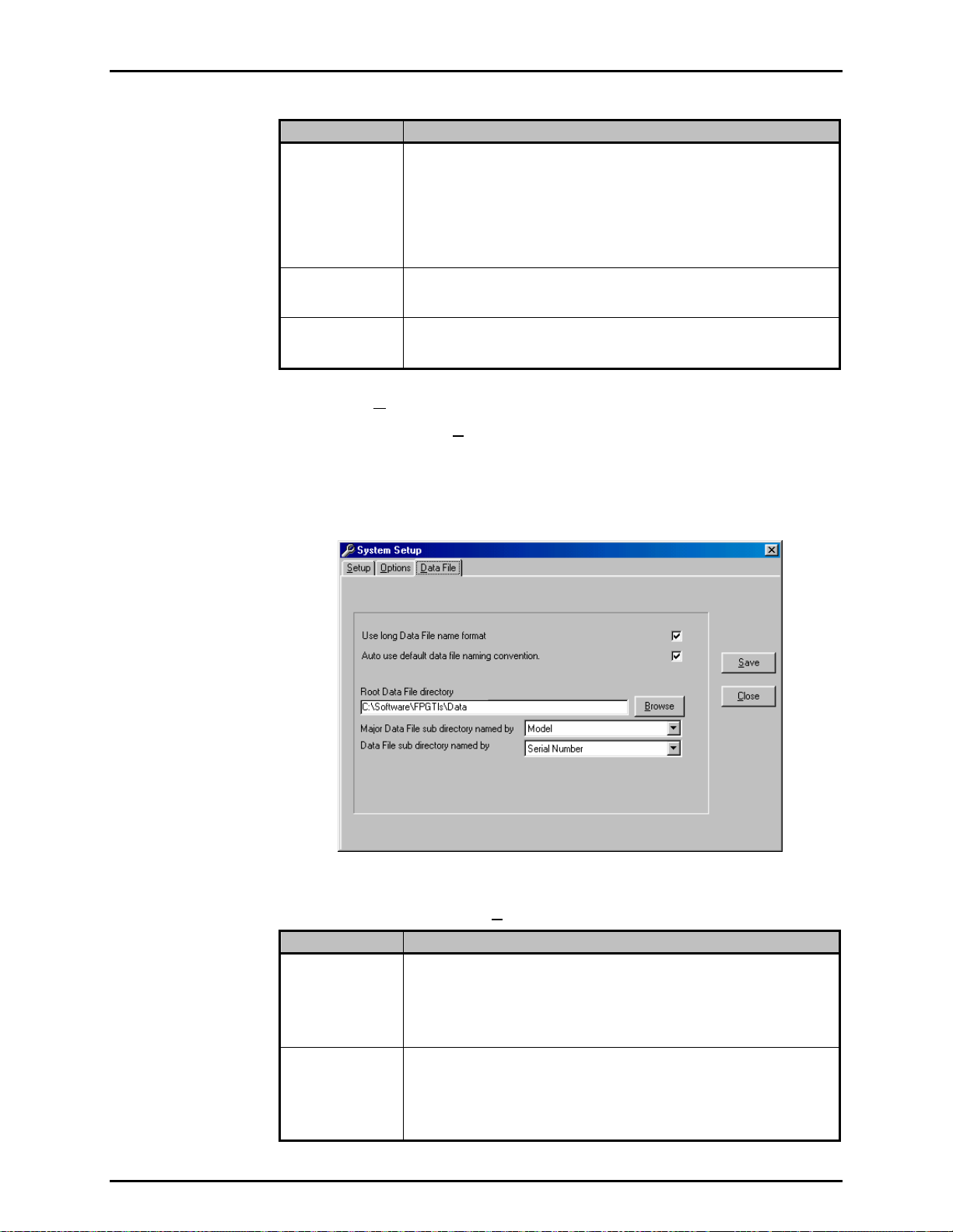
FPG8601™/VLPC™ OPERATION AND MAINTENANCE MANUAL
LABEL DESCRIPTION
Enable ION
Gauge
Vacuum Pump
RS232 Settings
Ion Gauge RS232
Settings
Check this box to allow FPG Tools to interface with the manifold ion gauge.
The ion gauge must be powered on and connected to the system PC
according to the <Ion Gauge RS232 Settings>. The ion gauge is used
by FPG Tools only when the manifold is zeroed (see Section 5.6).
The ion ga
<DUT Manifold> display.
The Granville Phillips Series 360 Ion Gauge system is the only ion gauge
directly supported by FPG Tools.
Select the RS232 port and settings that the manifold vacuum pump will use.
By default, the RS232 settings are 9600, N, 8, 1. The COM port used by
the vacuum pump is dependent on the PC used to run FPG Tools.
Select the RS232 port and settings that the ion gauge will use. By default,
the RS232 settings are 9600, N, 8, 1. The COM port used by the ion gauge
is dependent on the PC used to run FPG Tools.
uge can be controlled manually by using the tools on the
6.6.2.3 <DATA FILE>
The <System Setup>, <Data File> tab is used to set user preferences affecting
the Data File (*.dat) which records the data from a test run (see Section 9).
The pu
how to use them are provided in
Table 18. When selections are complete, click <OK> to save changes.
rpose of the [Data File] tab fields and settings as well as instructions on
Figure 31. <System Setup>, <Data File> Tab
Table 18. <Options>, <Data File> Tab Fields
FEATURE DESCRIPTION
Use long data file
name format
(check box)
Auto use default
data file naming
convention
(check box)
© 2007 DH Instruments, a Fluke Company Page 72
Check this option to use the long Data File naming convention as described
in Section 9.2.1. This feature is checked by default. Although FPG Tools is
a 32 bit Windows application, D
other location that does not support the long file naming convention. To
avoid file name truncation, uncheck this option to create default file names
that are 8 characters or less.
When this option is checked, test Data Files are automatically created when
[Run w/Point Log] or [Run Test Sequence] is selected. Otherwise, a
separate dialog box displays for each active DUT to allow the entry of the
data file name. In most cases, automatically naming the data file is desired.
However, when some specific tests are executed, it can be more convenient
to manually name the data files.
ata Files may be stored on a network or
Page 85
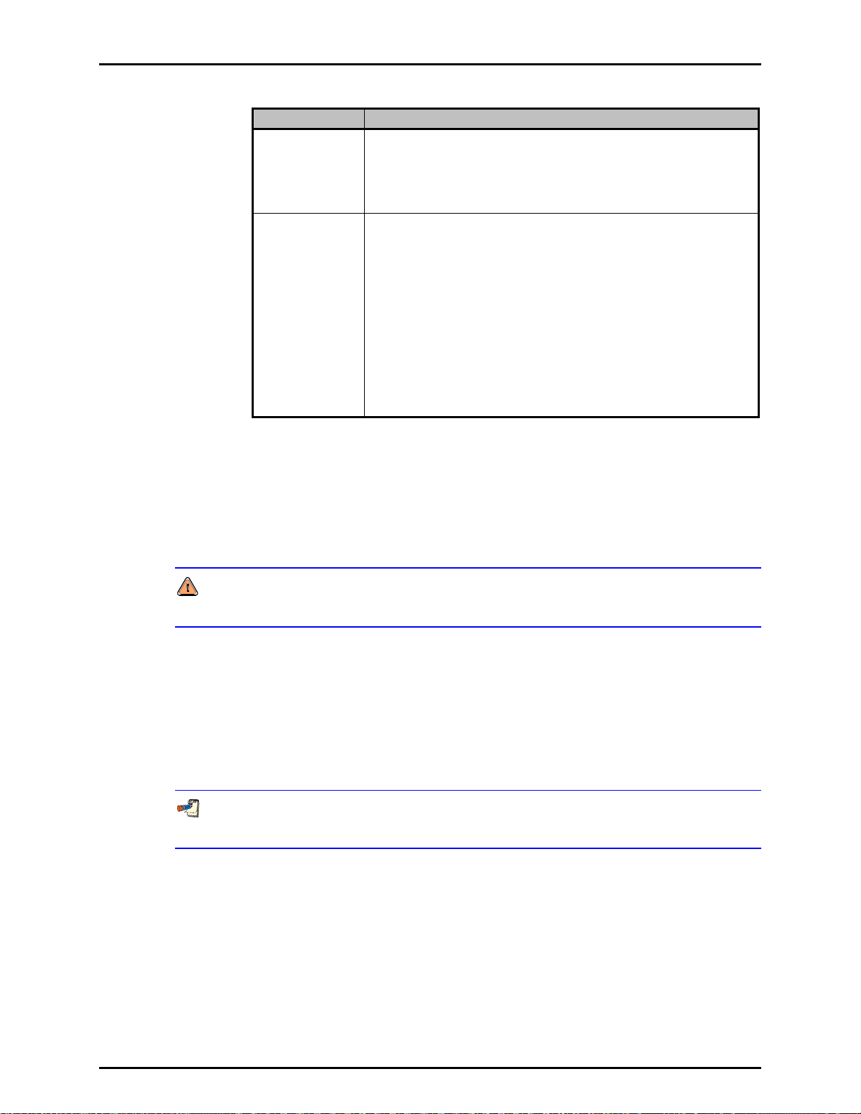
6. FPG TOOLS
FEATURE DESCRIPTION
Root Data file
directory
(text entry field)
Major Data File
sub directory
named by
Minor Data File
sub directory
named by
(drop down list box)
Defines the root directory to use when creating new DUT based
sub-directories and copying Data Files. The selected directory can be on a
network or on an internal hard drive. Any directory selection can be used
provided there is enough room to store test Data Files and that the location
is not write protected. Use the <Browse> button next to the entry field to
select a new or existing directory using a directory browsing tool.
FPG Tools generates default file names for Data Files (*.dat) it creates
when a test is run. It also creates and uses default directories for the Data
Files based on the DUT Definition on which the test was run. These DUT
dependent data directories are created as sub directories of the <Root Data
&
File directory>. This feature automatically sorts Data Files in DUT
dependent directories so that they can easily be retrieved when desired.
The <Major director y…> option determines the name of a sub directory in
the <Root Data File directory>. The <Minor directory..> determines the
name of a directory to create in the <Major directory…>. The choices are
DUT serial number, identification, model, manufacturer or record label.
In addition, <None> can be selected. The directory name will include the
full text of the DUT Definition field selected unless the <long file name…>
option is disabled or DUT information contains one of the following invalid
characters as part of the field: /, \, ?, :, *, <, >, |, or “. If so, the directory
name will contain all text up to the first occurrence of the character.
6.6.3 [FPG CALIBRATION SETUP]
FPG specific calibration information can be selected and entered using this option. Each
FPG has it’s own unique set of calibration values that must be entered into FPG Tools to
accurately determine the final FPG pressure. This is the most critical step in the process of
the initial configuration of FPG Tools. Default values in all other aspects of the program
setup will not effect the metrology of the system.
Make sure all data is entered in the proper units with the correct sign. Failure to
accurately enter FPG calibration information will result in invalid data.
Although most users will have only 1 FPG to set up, FPG Tools supports multiple FPG
calibration records. Use the <Display Selector> at the top of the screen to view calibration
information from other records. To edit a file, click the desired field and make the
necessary changes. When all edits are complete either choose [Save] to simply store
the edits. Or choose [Save as system selection] to activate this record for use when the
software enters a run mode. The active system selection always displays the <Record
Increment> in yellow. Use the [Add] feature to create a new data record or use the
[Remove] features to remove the currently selected data record.
FPG Calibration records cannot be modified when FPG Tools is in a run mode. The ability
to change and view FPG calibration information is restricted in the standard user level.
The following table summarizes the features of the <Calibration Setup Screen>. Refer to
the calculation section for more information on the use of these parameters.
Page 73 © 2007 DH Instruments, a Fluke Company
Page 86
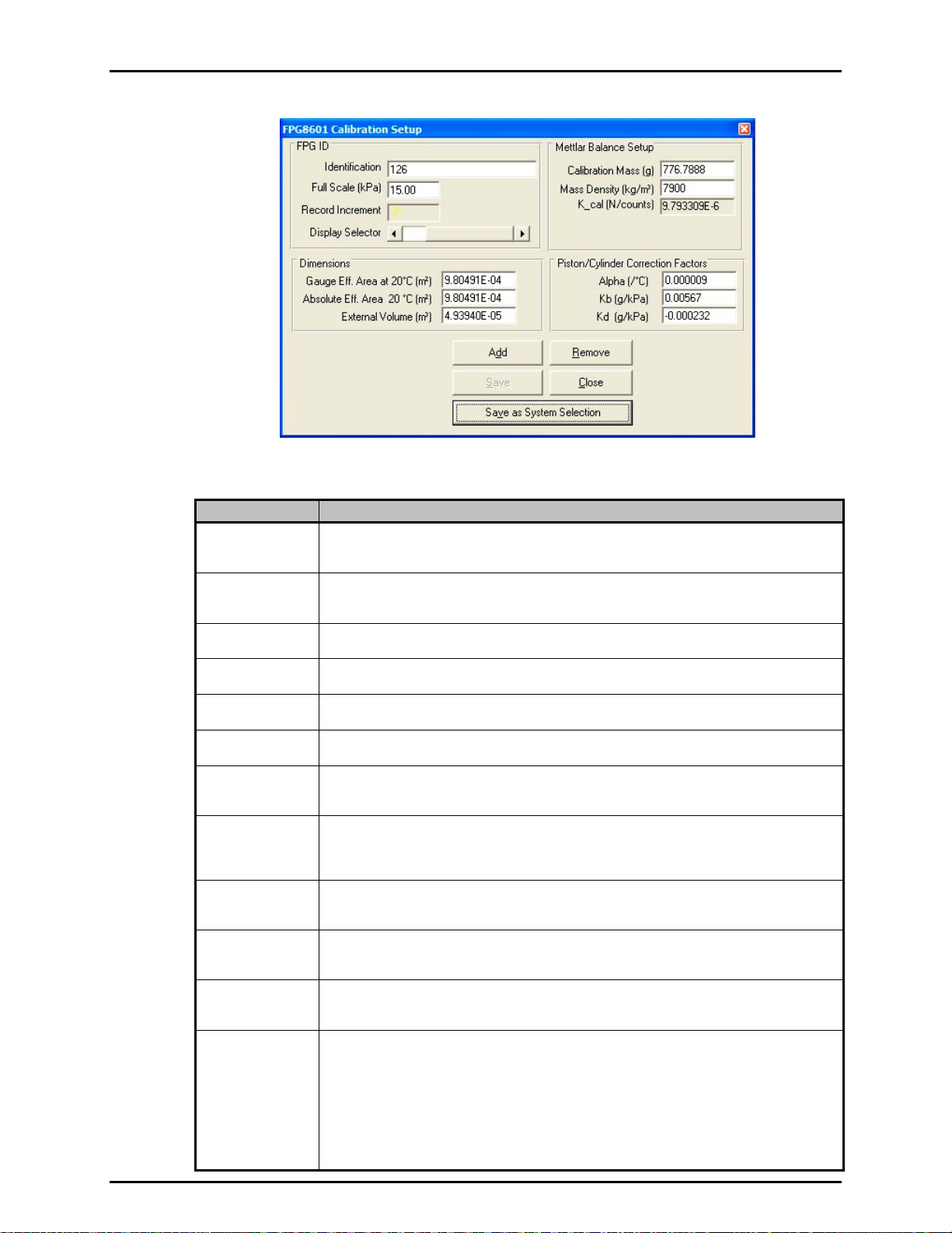
FPG8601™/VLPC™ OPERATION AND MAINTENANCE MANUAL
Figure 32. <FPG8601 Calibration Setup>
Table 19. <FPG8601 Calibration Setup> Options
LABEL DESCRIPTION
Identification
(text entry field)
Record
Increment
(display label)
Display Selector
(scroll bar)
Alpha (/°C)
(numeric entry field)
Kb (g/kPa)
(numeric entry field)
Kd (g/kPa)
(numeric entry field)
Gauge Area (m²)
(numeric entry field)
Absolute Area
(numeric entry field)
External Volume
(numeric entry field)
Calibration Mass
(numeric entry field)
Mass Density
(kg/m³)
(numeric entry field)
K_Cal
(numeric entry field)
Maximum 50 character length field representing a summary of the FPG calibration file.
Any information that easily identifies the unit can be entered into this field. The text entered
is logged in the data file.
Read only field representing the current record increment of the file being viewed. Changing the
position of the <Display Selector> automatically updates this value. When the current selection
represents the system selection, this field displays in yellow with an asterisk next to the number.
Use this horizontal scroll bar to view other saved FPG calibration files. Each scroll position
corresponds to a specific FPG record increment.
This is the combined temperature expansion coefficient for the FPG piston and cylinder.
Experimentally determined buoyancy effect due to changes in lubrication pressure.
Experimentally determined drag effect due to relative changes in lubrication pressure and
reference port pressure.
Experimentally determined effective area of the piston cylinder combination in gauge mode.
This value is used by default when the [Internal Limits], <Use area based on
measurement mode> (see Section 6.6.4.1) option is not selected.
Experimentally determined effective area of the piston cylinder combination absolute. Only
(m²)
under special circumstances should this value be different than the <Gauge Area> field.
The value entered is used only when the configuration selection <Use area based on
measurement mode> option is selected and the FPG is used in absolute measurement mode.
The volume of the piston and connecting parts. The parameter is used in buoyancy
(m³)
force calculations.
True mass value of the internal calibration mass.
(g)
Density of the calibration mass.
The last saved calibration factor. FPG Tools automatically updates this value when an
internal calibration is saved. K_cal is directly multiplied to several other compensation
factors to determine the final FPG pressure. Any error in the entry of this value will
completely invalidate the calculated pressure. Change this parameter by double clicking the field,
then entering the desired value in the input box. The input box displays the default value based
on the current local gravity entry, standard density of ATM, and the <Mass Density> parameter.
It is recommended that the default calibration factor should be used on all new calibration
files. When the file is used for a specific FPG, run the internal calibration manually by using
the [Internal Calibration] toolbar function (see Section 6.4.2).
© 2007 DH Instruments, a Fluke Company Page 74
Page 87

6. FPG TOOLS
6.6.4 [INTERNAL LIMITS]
The [Internal Limits] is provided to change limits and setup information that are
typically constant. Changes may be necessary for diagnosing problems or to provide more
restrictive limits in an attempt to obtain a better overall uncertainty. Make edits to the desired
fields then press the [Save] button to accept the changes. Closing the display without
pressing [Save] ignores all changes.
A thorough understanding of all settings in the [Internal Limits] option is required prior
to making changes. Make sure all data is entered in the proper units with the correct
sign. Failure to accurately enter limit information can result in the FPG pressure always
indicating a not ready condition.
With the exception of the first tab, all tabs in [Internal Limits] allow the adjustment of limits
specific to a specific type of measurement.
In most cases, the limits effect when FPG Tools
will provide a re-zero warning and force a “Not Ready” condition. Making a limit too small can
make it impossible to be “Ready” and making the limit too large can remove the power of the
limit all together. Sound limits are important to ensure that correction values associated with
a change in conditions remain small.
6.6.4.1 <SETUP>
The setup tab allows adjustment of diagnostics level setup parameters.
Figure 33. <Internal Limits> <Setup>
Table 20. <Internal Limits> <Setup> Options
LABEL DESCRIPTION
Setup load cell
during
initialization
(check box)
Use effective area
based on
measurement
mode
(check box)
Apply thermal
transpiration
correction to the
vacuum
reference sensor
(check box)
When checked, FPG Tools re-initializes the load cell’s internal parameters
as part of the initialization process of any run mode. This option should be
checked whenever the load cell parameters were manually modified since
the last use of FPG Tools.
Check this option to use the effective area setup in the <FPG Calibration
Setup> based on the current pressure measurement mode. This option
has no effect if the selected calibration file uses the same effective area for
absolute and gauge mode (see Section 6.6.3).
Check this box to apply the thermal transpiration correction to the FPG8601
vacuum reference sensor. By default this value is not checked because the
vacuum reference sensor is not calibrated with the thermal transpiration
correction active. In general, do not use this feature for normal operation
without consulting DH Instruments Technical service.
Page 75 © 2007 DH Instruments, a Fluke Company
Page 88

FPG8601™/VLPC™ OPERATION AND MAINTENANCE MANUAL
LABEL DESCRIPTION
reference orifice
Vacuum
diameter (mm)
(numeric entry field)
Vacuum
reference
temperature for
thermal
transpiration
correction
(numeric entry field)
Thermal
transpiration
correction factors
(numeric entry field)
ATM/Lube Switch
delay time
(scroll bar selection)
The minimum connection tube diameter between the vacuum reference
sensor and the FPG8601. This value is typically a diameter internal to the
vacuum reference sensor. The value is used only when thermal
transpiration is active for the vacuum reference sensor.
The steady state temperature of the vacuum reference sensor. The value
entered is used to determine the thermal transpiration correction when the
correction is active.
Coefficients <A>, <B> and <C> are standard thermal transpiration
correction factors (see Section 11.3.4). The values must be specified for
the active test g
gas will causes significant errors in the determination of the thermal
transpiration correction.
The time in seconds between atmospheric pressure readings. Use the
scroll bar to increase or decrease the switch delay time. Changes in
atmosphere (ATM) have a very small yet measurable effect on the FPG.
The change in ATM since the last zero results in a small buoyancy force
that is quantified by δN3 (see Section 2.7.3). While ATM is being read FPG
Tools is tempora
unnecessary delays to calibrations.
as. Assigning the coefficients for gases other than the test
rily halted. Therefore, making this time too small can add
6.6.4.2 <PRESSURE>
All limits related to pressure measurements made by the internal transducer are
defined on this tab. Do not confuse these pressure limits with actual FPG
calculated pressures. The purpose of each limit is defined on the table below.
When a pressure limit is exceeded an “L” or an “A” will be listed in the
<Status> category of the <Diagnostics Display>. This forces a “Not
Ready” condition.
Figure 34. <Internal Limits> <Pressure>
© 2007 DH Instruments, a Fluke Company Page 76
Page 89
6. FPG TOOLS
Table 21. <Internal Limits> <Pressure> Options
LABEL DESCRIPTION
Display warning if
lubrication pressure
changes from limit
by (+/- kPa)
(numeric entry field)
RPT stability
criterion
(numeric entry field)
Gauge mode
lubrication pressure
(numeric entry field)
Absolute mode
lubrication pressure
(numeric entry field)
Maximum deviation
form mode
appropriate
lubrication pressure
(numeric entry field)
Absolute mode,
vacuum reference
stability criterion
(numeric entry field)
Vacuum pump
speed at which the
ion gauge can be
activated
(numeric entry field)
Ion gauge pressure
at which degassing
can be turned on
(numeric entry field)
Enter a value that represents the maximum deviation of lubrication
pressure from it’s tare value. If the pressure changes by this amount, a
warning message will display and an “L” will appear in the <Status> label
of the <Diagnostics Display> (see Section
forces a “Not Ready” condition. The value entered should be small to
minimize the effect of the δN1 and δN2 corrections (see Section 2.7).
The maximum acceptable rate of change of pressure for any internal RPT
measurement. The criterion effects the limits on lubrication pressure,
ATM and reference pressure measurements. When the pressure
measurement exceeds the criterion, FPG Tools does not use the new
pressure in any calculations but will display the new pressure on the
proper run screen. Only stable pressure outputs are used in calculations.
The optimum lubrication pressure for gauge mode operation. The internal
FPG regulators must have been factory adjusted for this pressure. When
setting gauge measurement mode, the lubrication pressure must be within
the <Maximum deviation from mode appropriate lubrication
pressure> value prior to completing the transition.
The optimum lubrication pressure for absolute mode operation. The internal
FPG regulators must have been factory adjusted for this pressure. When
setting absolute measurement mode, the lubrication pressure must be
within the <Maximum deviation from mode appropriate lubrication
pressure> value prior to completing the transition.
When setting gauge or absolute measurement mode, this value
represents the maximum deviation from the target lubrication pressure
value. If FPG Tools is not able to achieve this pressure, the mode
transition will neither complete nor time-out.
In absolute mode when the [Config], [System Setup], <Use vacuum
reference sensor for absolute mode correction> option is selected, this
entry determines how stable the vacuum reference sensor must be to
allow a ready condition. Two consecutive readings (about 1s apart)
cannot differ by the value entered, otherwise, a "V" will appear in the
status indicator and the FPG pressure will be forced to a "Not Ready" state.
Enter the speed of the turbo pump required to achieve a pressure low
enough to safely turn on the ion gauge when zeroing the DUT manifold.
Typically, the maximum speed of the turbo pump should be entered. The turbo
pump cannot reach maximum speed until the pressure is on the order of 1 Pa.
Enter the maximum pressure at which the ion gauge’s degas option
should be turned on. This parameter is used only when the DUT manifold
is zeroed and the ion gauge is enabled (see Section 5.6).
6.3.7). This status code
6.6.4.3 <TEMPERATURE>
All limits related to temperature measurements made by both of the mounting
post PRT’s and the temperature sensor located inside the lubricating volume are
defined on this tab. Realize that the limits effect both temperature measurements,
however, only the mounting post PRT temperature is used in calculations.
The purpose of each limit is defined on the table below.
When a temperature limit is exceeded a “T” will be listed in the <Status>
category of the <Diagnostics Display>. This forces a “Not Ready” condition.
Both change in temperature and the rate of change of temperature have
adverse effects on the load cell. For this reason, always use the FPG in
stable laboratory conditions.
Page 77 © 2007 DH Instruments, a Fluke Company
Page 90

FPG8601™/VLPC™ OPERATION AND MAINTENANCE MANUAL
Figure 35. <Internal Limits> <Temperature>
Table 22. <Internal Limits> <Temperature> Options
LABEL DESCRIPTION
Temperature re-
zero limit (°C)
(numeric entry field)
The number entered should represent the maximum ± temperature
deviation allowed from the tare temperature. When this difference is
exceeded, a re-tare target message displays and a “T” will be included in
the run screen <Status> output.
Large temperature changes will cause zero drift in the FPG. For this
reason, the value entered should never exceed 1.0 °C. Typically .5 °C or
less is used.
Maximum
difference
between
temperature
sensors (°C)
(numeric entry field)
Maximum
temperature rate
of change (°C/s)
(numeric entry field)
Minimum
operating
temperature (°C)
(numeric entry field)
Maximum
operating
temperature (°C)
(numeric entry field)
The maximum absolute difference between the mounting post temperature
and the lubricating volume temperature. The value is not intended to
monitor the calibration offset of the sensors. The goal is to make sure the
lubricating volume temperature is not changing relative to the mounting post
temperature. If this is the case, the FPG is in unstable temperature
conditions and should not be used until temperature stabilizes.
Enter the maximum rate of change of either the mounting post or lubricating
volume temperature. Large temperature rates of change indicate unstable
conditions that will effect the overall stability of the load cell and resulting
FPG pressure.
Enter the minimum temperature value for which the FPG temperature
compensation is valid. The FPG is temperature compensated over a
temperature range that is centered about 24 °C. Changes in temperature
around this range will not effect the FPG as long as the rate of change is
small and the FPG is zeroed when temperature changes significantly.
Enter the maximum temperature value for which the FPG temperature
compensation is valid.
6.6.4.4 <HUMIDITY>
All limits related to humidity measurements by the humidity sensor located in the
lubricating volume are defined on this tab. Humidity is nominally controlled to
50 % during assembly by adjusting the proper regulators. As long as the
bubbling system is filled with water (see Section 8.2) and the FPG is purged
n changing measurement modes, the humidity should stay within the
whe
required limits. The purpose of each limit is defined in Table 23.
When a humidity limit is exceeded a “H” will be listed in the <Status>
category of the <Diagnostics Display>. This forces a “Not Ready” condition.
© 2007 DH Instruments, a Fluke Company Page 78
Page 91
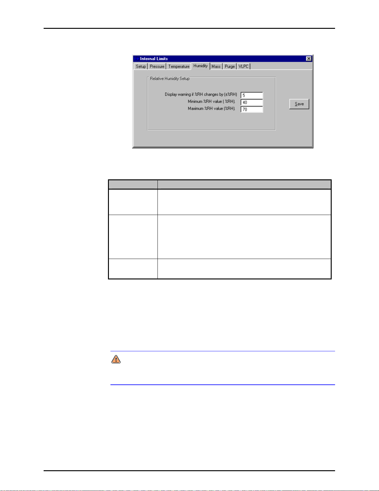
6. FPG TOOLS
Figure 36. <Internal Limits> <Humidity>
Table 23. <Internal Limits> <Humidity> Options
LABEL DESCRIPTION
Display a
warning if the
%RH changes by
(numeric entry field)
Minimum %RH
value
(numeric entry field)
Maximum %RH
value
(numeric entry field)
The maximum change in load cell humidity since the last system tare.
Large changes in humidity can be caused by the lack of water in the
bubbling system.
The minimum operating humidity. Using the FPG when the load cell
environment has a humidity less than this value can lead to invalid
measurements. The effect of humidity on the load cell dramatically
increases when humidity is small, < 40 %. In this condition, a small change
in humidity will have a large change on the load cell output.
If the minimum humidity cannot be obtained, make sure the bubbling system
contains water and that all pressure connections are secure and correct.
The maximum operating humidity. Using the FPG under high humidity
conditions can lead to unnecessary wear on internal system valves.
Typically, purging reduces the humidity within the necessary limits.
6.6.4.5 <MASS>
All limits related to the load cell output are defined on this tab. Specifically, the
stability criterion and limits on the internal calibration process. Since the internal
calibration process affects the actual slope of the FPG (see Section 5.3), take
cial care when adjusting these parameters. When an internal calibration is
spe
run manually, any limit related failure generates an error message specific to
the problem.
Internal calibrations run during automatic test sequences are not activated
when any of the internal calibration limits are exceeded. Make sure the limits
entered are reasonable for the test conditions.
Page 79 © 2007 DH Instruments, a Fluke Company
Page 92

FPG8601™/VLPC™ OPERATION AND MAINTENANCE MANUAL
Figure 37. <Internal Limits> <Mass>
Table 24. <Internal Limits> <Mass> Options
LABEL DESCRIPTION
Number of times
to lower the
calibration mass
when calibrating
(numeric entry field)
Maximum
deviation
between
calibration mass
indications
Load cell
stability criterion
for zeroing and
calibrations
(numeric entry field)
Maximum
deviation in
calibration factor
(numeric entry field)
Force tare
condition for
manual internal
calibrations
(check box)
The internal calibration process lowers and raises the internal calibration
mass as many times as specified by this field. The values are averaged
together and used in the determination of the calibration factor (see Section
5.3). The number of samples to average becomes important when
conditions are some
internal calibration will be used when the FPG is at a pressure.
Enter the maximum acceptable difference between internal calibration mass
values when the mass will be lowered multiple times. Use this limit to
prevent unacceptable amounts of system noise from biasing the internal
calibration results.
Enter the maximum ± change in counts allowed during the stability test used
prior to zeroing and running internal calibrations. The load cell output
cannot change by this amount. Using a value that is too large can allow
false stability readings for three consecutive readings.
The maximum change in the calibration factor between internal calibrations.
An error message displays when the calibration factor change exceeds this
limit when run manually and internal calibrations ran automatically during
tests are not activated.
Check this box to cause FPG Tools to vent all FPG pressure and place the
system in a tare (zero) condition prior to running the internal calibration.
When the value is not checked, the current load cell output is averaged and
subtracted from the resultant load cell output when the internal calibration
mass is lowered. This allows a user to check the span of the FPG at places
other than mid scale.
what unstable. This is typically the case when the
6.6.4.6 <PURGE>
All limits related to purging are defined on this tab. Purging is an important step
in obtaining humidity, pressure and temperature equilibrium in the load cell
volume. It is important to properly purge the FPG when changing measurement
modes and whenever the lubrication gas is changed. If the lubrication gas is
changed, the system should be purged not only by using this function, but by
© 2007 DH Instruments, a Fluke Company Page 80
also following the procedure outlined in Section 4.12.1.
This purge is not used to exhaust all gas from the test port of the FPG and
any connected DUT. To purge a DUT, set and vent several pressures prior to
using the system. A test sequence can be created to purge a DUT (see
Section 6.6.5).
Page 93

6. FPG TOOLS
Purging consists of opening a valve that exchanges gas in the lubricating volume
for a fixed amount of time. The valve is then closed for a fixed amount of time to
allow for stability. The change in humidity between the beginning and end of the cycle
is used to determine if the purge process should be repeated. Purging is repeated
until the humidity criterion is met or the <Operation Abort> function is used.
Figure 38. <Internal Limits> <Purge>
Table 25. <Internal Limits> <Purge> Options
LABEL DESCRIPTION
Duration of each
purge cycle
(numeric entry field)
Purge stability
delay
(numeric entry field)
Maximum %RH
change between
purging cycles
(numeric entry field)
Enter a value that specifies how long gas will be removed from the
lubricating volume. In gauge mode, if the limit is sufficiently long, the
lubrication pressure will approach ATM. In absolute mode, the lubrication
pressure will slowly approach vacuum. Completely removing all gas in the
lubricating volume is the goal of purging only when the gas has been
changed. Typically, the goal is to obtain a stable humidity value in the
proper range. Removing a small amount of gas several times is all that is
needed to accomplish this task.
The time in seconds that FPG Tools should wait prior to comparing the
before and after humidity values. If the time is not long enough to allow the
FPG regulators to re-fill the volume, the purging process will take longer
than necessary or may not obtain proper humidity conditions.
Maximum change between the humidity at the beginning of the purge and
the humidity after the stability test. If the humidity change exceeds this limit,
the purge cycle is repeated. With each successive purge cycle, the change
in humidity should decrease because the volume should approach the
target equilibrium humidity. Using a value too small for this field will keep
the FPG in a continuous purge loop. On the other hand if the value is too
large, the volume will not be properly purged.
6.6.4.7 <VLPC>
The minimum and default control limits of the VLPC are defined on this tab.
The active control settings used to determine a “Ready” condition are defined by
the active test sequence or the current setup in the <Settings> (see Section
6.6.1) option. When the hold setting is set too
determine the actual criterion imposed on the pressure “Ready/Not
Ready” indication. Each time a new pressure range is set, the default hold limits
specified on this tab are set.
There are separate default values for each gauge and absolute pressure range.
The available ranges and the corresponding percent of range hold limits are
available only after [Run], [Run Monitor] is used and the VLPC is enabled. The
available ranges are dependent on the specific setup of the VLPC.
small, the limits setup on this tab
Page 81 © 2007 DH Instruments, a Fluke Company
Page 94

FPG8601™/VLPC™ OPERATION AND MAINTENANCE MANUAL
Figure 39. <Internal Limits> <VLPC>
Table 26. <Internal Limits> <VLPC> Options
LABEL DESCRIPTION
Minimum hold
setting
(numeric entry field)
Minimum
pressure for hold
criterion (Pa)
(numeric entry field)
Maximum
pressure, range
multiplier
(numeric entry field)
The smallest percent of range value that can be used for the hold criterion in
the specified pressure measurement mode. FPG Tools generates a
warning message if a hold limit smaller than this value is setup in a test
sequence or in the <Settings> option.
The minimum pressure that can be used as the hold limit in the specified
pressure measurement mode. Attempting to control a pressure below the
resolution of the FPG can make it impossible to obtain a “Ready” indication.
The value entered multiplied by the active VLPC range determines the
maximum allowable system pressure. The idea is to protect sensitive
DUT's from overpressurization. In most cases, the value should be 1.1.
This allows a 10 % overshoot of the active VLPC range. When the pressure
limit is exceeded, VLPPS Tools automatically vents all system pressure and
connects the test and reference ports of the VLPPS to remove any
differential pressure. Some DUT's may require a small portion of the active
VLPC range. In this case, use a multiplier less than 1 to effectively limit the
useable range.
Default Absolute
Mode Hold Limits
(numeric entry field)
Default Gauge
Mode Hold Limits
(numeric entry field)
The VLPC does not significantly overshoot pressure. However, loss of
the VLPC valve pressure supply can cause an increase in pressure beyond
the range of the VLPC.
Without this limit, a DUT would be over pressurized by selecting the wrong
test sequence or by accidentally entering the wrong target pressure value.
Each time the VLPC changes to the specified absolute pressure range, the
hold limit specified for the selected range is set by default. The hold limit
can be changed by using the [Config], [Settings] option.
Each time the VLPC changes to the specified gauge pressure range, the
hold limit specified for the selected range is set by default. The hold limit
can be changed by using the [Config], [Settings] option.
© 2007 DH Instruments, a Fluke Company Page 82
Page 95

6. FPG TOOLS
6.6.5 [DUT SELECTION]
DUTs can be used in FPG Tools by first creating them using the DUT Editor (see
Section 6.8). Then by activating them using the [Sy
menu choice. Up to 5 DUTs can be activated at any given time with FPG Tools.
Select the desired DUT from the list of available DUTs or press the button next to
the list to select DUTs by using the DUT selector. Enter a serial number and ID
for DUTs that are setup as profiles. Finally, edit the RS232 settings or the IEEE-488
address as required by the current setup. Press the <Activate DUT(s)> button
to initialize and use the selected DUTs. Remote DUTs are first sent their
initialization commands. The output of each DUT is the polled by repeatedly
sending each DUT it’s set of read commands (see Section 6.8.2.6.5). The output
of each
DUT displays on the <Run Display>. To abort the polling of DUTs,
select the <Deactivate DUT(s)> menu choice.
A separate data file is created for all active DUTs when any run option is
selected that involves the creation of a data file.
Press the backspace key to remove an individual DUT Type.
stem Setup], [DUT Selection]
Figure 40. <DUT Selection & I/O Setup>
Table 27. <DUT Selection & I/O Setup> Options
LABEL DESCRIPTION
DUT Type
(drop down list box)
Clear All DUTs
(command button)
Serial Number
(conditional text entry)
Identification
(conditional text entry)
Interface
Settings
(conditional text entry)
Activate DUTs
(command button)
Deactivate DUTs
(command button)
Cancel
(command button)
A list of all DUTs setup using the DUT definition editor (see Section 6.8).
Press the button next to the list of DUTs access the DUT selector. Press
the <BackSpace> button on the keyboard to remove an individual DUT.
Clears the entire list of selected DUTs.
The serial number specified in the DUT definition appears in this field if the
DUT is setup as a definition. If the DUT is a profile, the field will be blank.
The identification specified in the DUT definition appears in this field if the
DUT is setup as a definition. If the DUT is a profile, the field will be blank.
Displays the type of interface settings to use for the DUT Definition. Edit
this field as required for RS232 and IEEE-488 DUTs.
Press this button to begin polling all remote DUTs.
Press this button to stop polling all remote DUTs.
Aborts the DUT selection without saving changes.
Page 83 © 2007 DH Instruments, a Fluke Company
Page 96

FPG8601™/VLPC™ OPERATION AND MAINTENANCE MANUAL
6.7 TEST SEQUENCE EDITOR
All Test Sequences are created or edited using the Test Sequences Editor. When editing a test, verify
that each editor tab contains the proper information. This will help to avoid conflicts when using the Test
Sequence in [R
information on the features and entry fields of the Test Sequences Editor.
The Test Sequence Editor is made up of multiple sections:
<Toolbar> (see Section 6.7.1) Includes tools to identify and select Test Sequences and
<Points> Table (see Section 6.7.2) Lists the pressure, range change and tare points included in
un Test Sequence] run mode. Refer to Sections 6.7.1 through 6.7.5 for detailed
icon
s to create, save, copy and delete sequences.
the test
procedure. Test points can be edited in the table or
using the auto fill feature under the <Points> tab.
<Points> Tab (see Section 6.7.3) Provide
s a short cut method for filling in the pressure
<Points> table.
<Sequence> Tab (see Section 6.7.4) Defines/modifies test point
time, averaging time and the number of test cycles.
<Control> Tab (see Section 6.7.5) Specifie
s how pressure will be controlled and what criterion
to use when the test is run.
6.7.1 TOOLBAR
All fields above the display tab on the Test Sequence Editor are considered part of
the toolbar. The toolbar not only identifies which test is active, but also provides tools to
create, delete, save, restore, identify and select tests.
Figure 41. Test Sequence Editor, <Toolbar>
Table 28. Test Sequence Editor, <Toolbar> Options
FEATURE DESCRIPTION
Test record label
(required text
entry field)
This field is analogous to a file name. The text entered should make the test easily
distinguishable from other tests. Up to 40 characters can be used in the field.
execution aspects including dwell
Do not use the following characters: \,/, :, *, ?, “, <,>, |, a comma or tab character.
These characters will cause problems when importing the Data File.
Viewing Test
(label)
Editing Test
(label)
(toolbar button)
(toolbar button)
© 2007 DH Instruments, a Fluke Company Page 84
Identifies the current alphabetical sort position of the test in the editor based on the <Test
Record Label>. As the sort order changes, this field also changes. The notation is
“Current Test /Total number of tests”.
Identifies the sort identification of a test that is being edited. This field does not display
when no edits have been made. As the sort order changes, this field also changes.
Saves changes to an edited Test Sequence. This field is not available when edits have not
Save
been made. Any test conflicts result in error messages when saving. These conflicts must
be resolved before saving.
Creates a new Test Sequences with default information.
New
Page 97

6. FPG TOOLS
FEATURE DESCRIPTION
Copy
(toolbar button)
Restore
(toolbar button)
Delete
(toolbar button)
Open/Select
(toolbar button)
Scroll Select
(scroll bar)
Copies the contents of the current Test Sequence to a new Test Sequence. The <Record
Label> of the copied test includes the text “Copy”. This is the only difference between the
original Test Sequence and the copy. Make sure the new Test Sequence is properly
updated before saving.
Restores the Test Sequence to the last saved state. Use this feature to abandon edits
made to a Test Sequence before saving. If a new test was created using the <New>
option, the restore button is nonfunctional.
Deletes the current Test Sequence. A message prompt for confirmation displays prior to
removing the Test Sequence.
Displays the Test Sequence Selector loaded with a sorted list of the tests. The selected
test will display in the Test Sequence Editor.
Scrolls to the next Test Sequence according to the current alphabetical sort order of the
<Test Record Label>.
6.7.2 <POINTS> TABLE
The Test Sequence <Points> table is used to define and display the pressure points and
FPG tares that make up the test sequence. Pressure, range change and tare points can be
added to the sequence by using the [Insert] button.
Delete test points from the point sequence by double clicking the point. Click on any tare,
or range change image to remove the tare from the test sequence.
Figure 42. Test Sequence Editor, <Test Points> Table
The purpose of the <Points> table’s fields and settings as well as instructions on how to use
them are provided in Table 29.
Page 85 © 2007 DH Instruments, a Fluke Company
Page 98
FPG8601™/VLPC™ OPERATION AND MAINTENANCE MANUAL
Table 29. Test Sequence Editor, <Points> Options
FEATURE DESCRIPTION
Point Type
Indication
(label)
Insert
(action button)
Indicates how pressure point values in the <Points> table will be interpreted when the test
is run. The choices are all available pressure units and <%DUTFS>. If the indication is
<%DUTFS>, when the test is run, the pressure points will be calculated from the DUT input
span (see Section 6.6.2.3). Specifying points in <
common test procedure that runs the same point distribution for DUTs with different
ranges. If a DUT is not specified, FPG Tools generates an error when the Test Sequence
is selected. To change the point type, use the Test Sequence <Points> tab.
Clicking [Insert] causes a pop-up window display with the following insertable options:
The cursor changes when an [Insert] option is selected. Click the text box of the point
that you would like to effect. Clicking any other area aborts the [Insert] function.
• Tare Point changes the cursor into a tare icon that can be dropped onto the desired
point for a tare of the FPG to occur at that point. A tare icon will appear before the test
point. Click the tare icon to remove it. If the Test Sequence <Sequence> tab (see
Section 6.7.4) specifies a fixed taring sequence, this selection is disabled.
• Insert P
oint changes the cursor into a pencil icon that can be dropped on any point to
insert a blank point at that location. The selected point (and all subsequent points) then
shift down, leaving a blank point available for entry. Double click any test point to
remove it from the list.
• Range Change changes the cursor into a range selection icon that can be dropped on
any test point. A range change occurs before the point, so the icon will appear above
the selected test point and before the tare icon if present. FPG Tools will only change
the VLPC pressure range if a pressure point between the selected point and the next
range change (or end of test) requires a pressure that exceeds the current VLPC range
or if a VLPC range is better suited for the pressure points.
%DUTFS> is useful in setting up a
Test Point Table
(numeric entry fields)
When ranges are changed using this option, the default VLPC hold limits are used after
each range change instead of the hold limit specified on the <Control> tab.
• Tare Check changes the cursor into a tare check icon that can be dropped onto any test
point. Tare checks set the FPG to the zero condition (see Section 5.2.1), waits for
then averages for the specified averaging time up to 15s. The averaged output
stability
is logged to the data file like any other test point. The dwell time is ignored. Tare checks
are useful when trying to quantify zero drift during a test.
The test point table lists the test pressure points that will be run in sequential order when
the Test Sequence is executed. The values entered are assumed to be in the unit
specified by the <Point Type Indication> at the top of the table. If the test points exceed
the 22 points that are normally displayed, the scroll bar at the bottom of the table can be
used to scroll to additional columns of test points. Up to 100 test points can be included.
The test point table can be filled in by placing the cursor in the test point field and editing
the desired test point value. It can also be filled in automatically using the <Points> tab.
The test point table can be cleared using <Clear> on the <Points> tab.
© 2007 DH Instruments, a Fluke Company Page 86
Page 99

6. FPG TOOLS
6.7.3 [POINTS] TAB
The Test Sequence <Points> tab is used to set the <Test Point Type> and provides a short
cut to fill in the <Points> table automatically, if desired (see Section 6.7.2
Figure 43. Test Sequence Editor, <Points> Tab
The purpose of the <Points> tab fields and settings as well as instructions on how to use
them are provided in Table 30.
Table 30. Test Sequence Editor, <Points> Tab Fields
).
FEATURE DESCRIPTION
Test Point Type
(drop down list)
Starting Point
(numeric entry
Ending Point
(numeric entry
Step Value
(numeric entry
Ascending/
Descending Points
(drop down list
selection)
Auto Fill
(action button)
(action button)
Determines how the pressure point values in the <Points> table will be interpreted when
the test is run. Use the drop down list to select the type. The choices are: <%DUTFS> or
any supported pressure unit. If the indication is <%DUTFS>, when the test is run, the test
points will be calculated from the DUT output span defined in [Config], [DUT Editor] (see
Section 6.8). The pressure unit will be defined by the DUT. Specifying points in
<%
DUTFS> is useful in setting up a common test procedure that runs the same point
distribution for DUTs with different ranges. The current point type selection is indicated at
the top of the <Points> table (see Section 6.7.2
Defines the first point of an Auto Fill test point sequence. Entering a value in this field has
no affect until [A
field)
Defines the last point of an Auto Fill test point sequence. Entering a value in this field has
no affect until [A
field)
Defines the increment used by [Auto Fill] to determine test points between the starting
point and ending point. Entering a value in this field has no affect until [A
pressed.
field)
Selects whether the [A
point only or from starting point to ending point and back to starting point. If <Yes> is
selected, the test point sequence is from starting point to ending point and back to starting
point. The ending point is repeated to provide proper point weighting when calculating best
fits from the test data. If this repeated point is not desired, double click the point after the
points have been filled in. Making a selection has no affect until [A
Clicking [Auto Fill] causes the test point table to clear and fills in the table with the points
calculated from the auto fill instructions: <Starting Point>, <Ending Point>, <Step
Value>, < Ascending/Descending Points>. If the values are such that the distance from
starting point to ending point is not an even multiple of the step value, the last step value is
adjusted to end exactly on the ending point. Points set up by [A
directly in the <Points> table and new points can be inserted at any point using the
<Points> table [Insert] button (see Section 6.7.2
Clear
Clicking [Clear] at any time causes all entries in the test point table to clear.
uto Fill] is pressed.
uto Fill] is pressed.
uto Fill] point sequence will run from the starting point to ending
).
uto Fill] is pressed.
uto Fill] can be edited
).
uto Fill] is
Page 87 © 2007 DH Instruments, a Fluke Company
Page 100
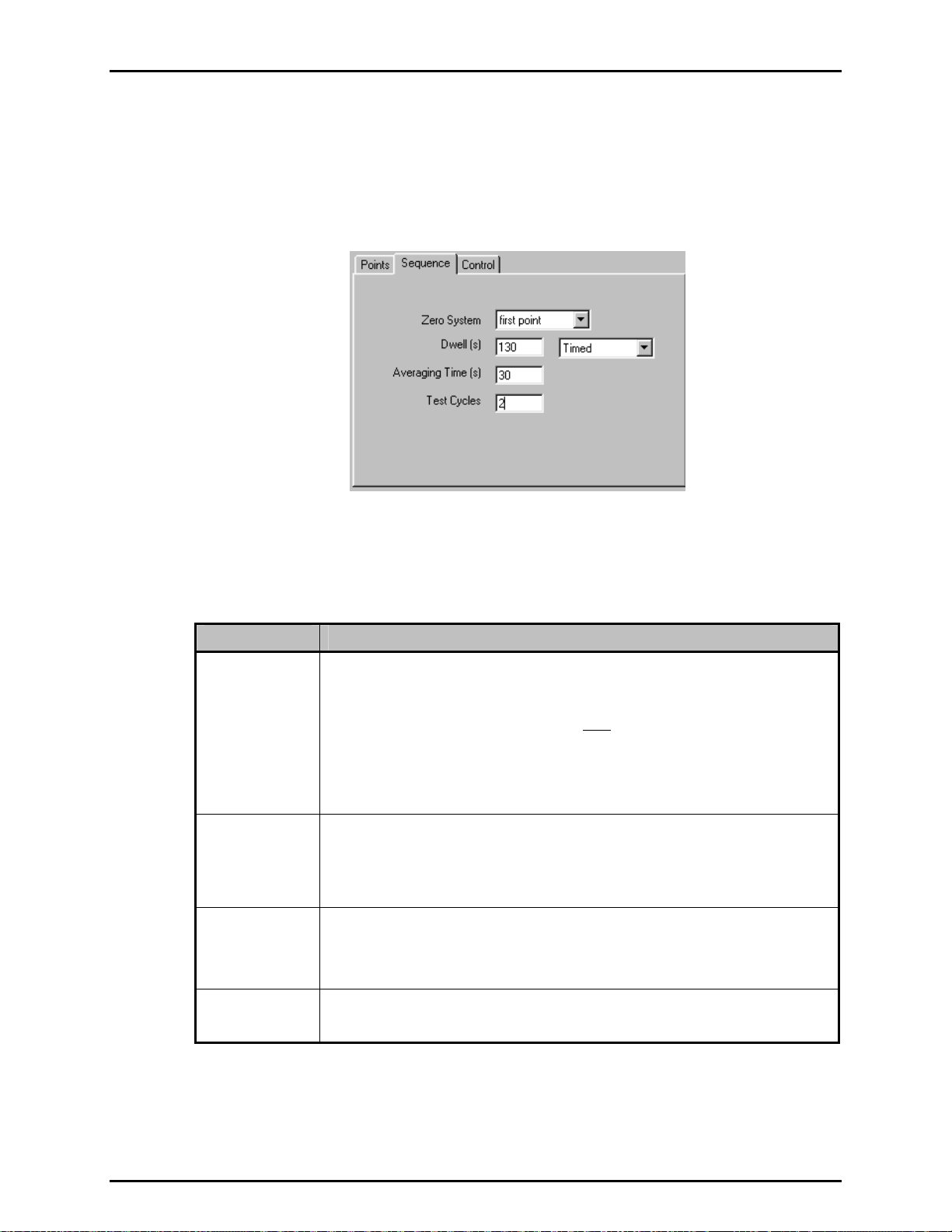
FPG8601™/VLPC™ OPERATION AND MAINTENANCE MANUAL
6.7.4 <SEQUENCE> TAB
The Test Sequence <Sequence> tab is used to specify details of how the test points of a test
will execute. This includes defining dwell and data reading parameters as well as the number
of times to run the test (number of cycles). Note that the order of the fields of the sequence
tab follows the order of execution of the different steps of each pressure point when a test is
actually run.
Figure 30. Test Definition Editor, <Sequence> Tab
The purpose of the <Sequence> tab’s fields and settings as well as instructions on how to
use them are provided in Table 31.
Table 31. Test Sequence Editor, <Sequence> Tab Fields
FEATURE DESCRIPTION
Zero System
(required drop
down list selection)
Dwell
(required entry
field and drop
down list selection)
Averaging
Time(s)
(required entry
field and drop
down list selection)
Number of Test
Cycles
(required entry field)
Use the drop down list to select the pressure points at which the FPG should be zeroed.
The tare occurs before the test pressure is set. After taring, the target pressure is set and
the Test Sequence proceeds with the stability test. There are three (3) choices:
• Selected points: Uses the tare points manually inserted into the sequence using the
<Points> table [Insert] option (see Section 6.7.2
• First point: Automatically adds a tare at the first test point. The <Points> table [Insert
Tare Point] option is not active when this choice is selected.
• All points: Automatically inserts a tare at every test point in the test point table. When
new points are added, they automatically receive a tare when this choice is selected.
The <Points> table [Insert Tare Point] option is not active when this choice is selected.
Dwell is a pause that occurs following the stability test, prior to taking averaged test data at
each pressure point. When <Dwell> is set to <Timed>, FPG Tools dwells at each test
point for the specified <Dwell Time>, 0 – 999s. When <Dwell> is set to <Manual>, FPG
Tools dwells at each test point until <OK> is clicked on the <Continue Test> pop-up. This
feature can be used to synchronize readings or to pause operation during pressure setting,
for example to make adjustments to the DUT.
Determines a fixed time over which reference and DUT readings are averaged when taking
data at each pressure point. FPG Tools averages for the fixed <Averaging Time>
entered, 0-999s. As many readings as possible are taken during the averaging period.
FPG Tools can run up to 10 test cycles in one test. A test cycle includes setting and taking
data at each of the pressure points in the <Points> table. When more than one test cycle
is specified. Data from multiple cycles is included in a single Data File (see Section 9.2).
).
© 2007 DH Instruments, a Fluke Company Page 88
 Loading...