

Page 1
CLKT, CLKTO, CLV
Infrared Window
Installation Guide
Introduction
The Infrared Window is a precision made accessory
which, when accurately installed, will give years of trouble
free service. Read and understand these instructions
thoroughly before attempting to install the units.
All of the items in Table 1 are available from Fluke.
Model Application Type Size
CLKT Outdoor 3, 12
CLKTO, CLV Indoor 1
PN 3783652
June 2010 Rev.1, 3/11
© 2010-11 Fluke Corporation. Product specications are subject to
change without notice. All rights reserved. Printed in UK.
Table 1.
2
″, 3″, 4″
3
″
How to Contact Fluke
To contact Fluke, call one of the following telephone
numbers:
● Technical Support USA: 1-800-44-FLUKE
(1-800-443-5853)
● Calibration/Repair USA: 1-888-99-FLUKE
(1-888-993-5853)
● Canada: 1-800-36-FLUKE (1-800-363-5853)
● Europe: +31 402-675-200
● Japan: +81-3-3434-0181
● Singapore: +65-738-5655
● Anywhere in the world: +1-425-446-5500
Or, visit Fluke’s website at http://www.uke.com/
irwindows.
To view, print, or download the latest manual supplement,
visit http://us.uke.com/usen/support/manuals.
Safety Information
Warning
To prevent damage or injury:
● Follow these instructions.
● Comply with local and national safety
requirements when working in hazardous
locations.
● Wear appropriate eye and ear protection.
Before You Start
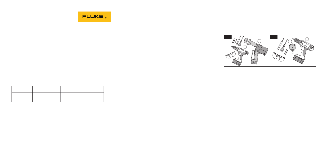
The installation may be carried out by using either an
electro-hydraulic hole punch (Figure 1, Item 1) or a
circular hole saw (Figure 2, Item 1).
1
2
Tools required:
1. Electro-hydraulic punch (Figure 1) or hole saw
(Figure 2)
2. Drilling machine
3. Conedrill
4. Pozidrive screwdriver
5. Center punch
6. 6 mm (1/4″) high-speed twist drill
7. Tapping drill:
for 50 mm (2″) units use 2.78 mm (7/64″)
for 75 mm (3″) units use 3.57 mm (9/64″)
for 100 mm (4″) units use 3.57 mm (9/64″)
8. Digital vernier calipers.
2
1
1
2
Page 2
4
5
6
7
3
INFRARED
CLKT
WINDOW
TYPE: 3, 12
INDOOR / OUTDOOR USE
-
CLKT
FLK
075
CLKT, CLKTO, CLV
Infrared Window
Installation Guide
The Infrared Window is a precision made accessory
which, when accurately installed, will give years of trouble
free service. Read and understand these instructions
thoroughly before attempting to install the units.
All of the items in Table 1 are available from Fluke.
Table 1.
Model Application Voltage Level Type Size
CLKT Outdoor All 3, 12
″, 3″, 4″
2
CLKTO Indoor Medium 1
″
3
PN 3783652
TAG NO.
June 2010
change without notice. All rights reserved. Printed in UK.
CHECK BEHIND BEFORE DRILLING
Getting Started
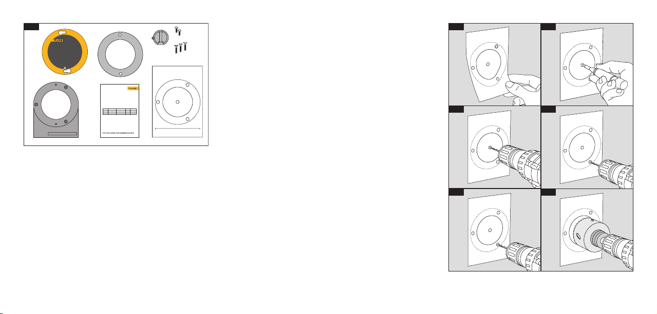
Step 1: Unpack and Check
When your Infrared Window arrives, carefully unpack the
unit.
Remove the two front security screws and lay out
the components. Check that you have all of the parts
(Figure 3).
1. Security screws (2)
2. Security cover (1)
3. 2-hole gasket (1)
4. Fixing screws (various)
5. Drilling template (1)
IMPORTANT
6. Installation instructions (1)
7. Mounting frame (1)
Step 2: Fit the Drilling Template onto a Flat Surface
Having decided on the correct position for the unit, select
the drilling template. Peel off the back and stick to the
panel with the wording horizontal (Figure 4).
Step 3: Center Punch
Using the center punch, punch the xing holes and
center hole as marked (Figure 5).
Step 4: Drill Center Hole
Using the 6 mm (1/4″) twist drill, drill out the center hole
(B) (Figure 6).
● For 50 mm (2″) unit, proceed to step 5.
● For 75 mm (3″) and 100 mm (4″) units, proceed to step 6.
Step 5: Drill Fixing Holes
Using the 2.78 mm (7/64″) twist drill, drill out the xing
holes (Figure 7).
● If using hole saws, proceed to step 7(A).
● If using the hole punch, proceed to step 8(A).
Step 6: Drill Fixing Holes
Using the 3.57 mm (9/64″) twist drill, drill out the xing
holes (Figure 8).
● If using hole saws, proceed to step 7(A).
● If using the hole punch, proceed to step 8(A).
98
Page 3

10
11
12
13
16
17
18
INFRARED
WINDOW
CLKT
Step 7(B): Enlarging the Center Hole (Hole Saw)
Using the 6 mm (1/4″) hole as a pilot hole, enlarge the
center hole using the selected hole saw (Figure 9). Deburr all of the holes and treat as required. Proceed to
TYPE
INDOOR / OUTDOOR USE
-
075
FLK
:
3, 12
CLKT
step 9.
Step 8(A): Enlarging the Center Hole (Hole Punch)
Refer to the hole punch manual and follow all safety
procedures.
From Table 3, select the correct drawbar/punch/die/kwik
INFRARED
WINDOW
CLKT
stepper combination.
Using the Kwik Stepper, enlarge the 6mm center hole
(Figure 10) to the size shown in Table 3. Proceed to step
:
TYPE
INDOOR / OUTDOOR USE
-
075
FLK
3, 12
CLKT
8(B).
Table 3.
Infrared
14
15
Step 7(A): Enlarging the Center Hole (Hole Saw)
From Table 2, select the correct size of hole saw. Proceed
to step 7(B).
Infrared Window Size Hole Saw Size
50 mm (2″) 43 mm (1-3/4″)
75 mm (3″) 68 mm (2-5/8″)
Table 2.
Window Size
50 mm (2″) 43.2 mm/1.7″ 20 mm/0.8″ 06974/04013
75 mm (3″) 69.9 mm/2.75″ 20 mm/0.8″ 04247/04246
100 mm (4″) 92 mm/3.62″ 20 mm/0.8″ Hole Saw Only
Step 8(B): Enlarging the Center Hole (Hole Punch)
Referring to Table 3, and following the instructions in the
hole punch manual, punch out the center hole (Figure 11).
Size K/Step
100 mm (4″) 93 mm (3-5/8″)
Greenlee
Punch/Die/PN
Page 4

Step 9: De-Burr the Holes, Remove any Shavings and
the Self Adhesive Template
Degrease the front panel.
Step 10: Fix Infrared Window
Peel off the protective cover from the rear panel gasket on
the Infrared Window’s mounting frame (Figure 12).
Align the xing holes and rmly press the Infrared Window
into place (Figure 13).
Using the correct sized screwdriver and the countersunk
screws provided, x back the Infrared Window
(Figure 14).
Gradually advance each xing until the gasket is seen to
compress evenly. Refer to Table 4.
Step 11 - Fitting Security Cover
Peel off the cover from the 2-hole gasket (Figure 15).
Align the gasket with the two xing holes positioned
vertically and press the gasket into position (Figure 16).
Fit the security cover using the two security screws
provided (Figure 17).
The Infrared Window is ready to use. Remember to
remove the cover before imaging (Figure 18).
Gasket Compression Table
Tighten taptite screws until gasket compresses as listed
in Table 4.
Note
Take all measurements with digital vernier calipers.
Table 4.
2″ Compression Table
Standard Gasket Premier Gasket
U/C C U/C C
16.8 mm 16.3 mm 16.3 mm 15.0 mm
0.663″ 0.643″ 0.643″ 0.591″
3″ Compression Table
16.8 mm 16.3 mm 16.3 mm 15.0 mm
0.663″ 0.643″ 0.643″ 0.591″
4″ Compression Table
20.4 mm 19.9 mm N/A N/A
0.805″ 0.784″ N/A N/A
U/C = Overall dimension - Exterior of security
cover to front face of the panel with gasket
uncompressed.
C = Overall dimension - Exterior of security cover to
front face of the panel with gasket compressed.
 Loading...