

Page 1

Victoreen®
943-25, 943-25A, 943-25B, 943-25T,
943-25TA, 943-25TB, 943-26, 943-26A,
943-26B, 943-26TT, 943-26TA, 943-26TB
Beta Detectors
March 2005
Manual No. 943-25-1 Rev. 2
©2004, 2005 Fluke Corporation, All rights reserved. Printed in U.S.A.
All product names are trademarks of their respective companies
Users Manual
Page 2

Fluke Biomedical
Radiation Management Services
6045 Cochran Road
Cleveland, Ohio 44139
440.498.2564
120 Andrews Road
Hicksville, New York 11801
516.870.0100
www.flukebiomedical.com/rms
Page 3

Table of Contents
Section 1: Introduction................................................................................................ 1-1
1.1 General Description ..................................................................................... 1-1
1.2 Application ................................................................................................... 1-1
1.3 Specifications............................................................................................... 1-1
1.4 Functional Description ................................................................................. 1-2
1.5 Receiving Inspection.................................................................................... 1-3
1.6 Storage ........................................................................................................ 1-3
1.6.1 Control of Items in Storage..................................................................... 1-3
1.6.2 In Case of Fire........................................................................................ 1-3
1.6.3 Removal from Storage............................................................................ 1-3
1.7 Procedures, Warnings, and Cautions .......................................................... 1-3
Section 2: Operation.................................................................................................... 2-1
2.1 Installation.................................................................................................... 2-1
2.2 Detector Operation ...................................................................................... 2-1
2.3 Detector Replacement Parts........................................................................ 2-2
Section 3: Theory of Operation................................................................................... 3-1
3.1 Scintillator and Photomultiplier Tube ........................................................... 3-1
3.2 Preamplifier.................................................................................................. 3-1
Section 4: Maintenance, Calibration, and Troubleshooting..................................... 4-1
4.1 Maintenance ................................................................................................ 4-1
4.1.1 Detector Disassembly............................................................................. 4-1
4.1.2 Detector Assembly ................................................................................. 4-1
4.2 Calibration.................................................................................................... 4-2
4.3 Calibration Where Calibration Date is Available .......................................... 4-2
4.4 Calibration Where Detector is a Replacement Part ..................................... 4-3
4.5 Troubleshooting ........................................................................................... 4-3
4.6 Safety Related Detectors ............................................................................. 4-4
4.7 Commercial Detectors ................................................................................. 4-4
4.7.1 Preliminary ............................................................................................. 4-4
4.7.2 Dynode Test Measurement .................................................................... 4-5
4.7.3 Preamplifier Checkout ............................................................................ 4-5
4.8 Replacement Parts ...................................................................................... 4-6
Appendix A: Applicable Drawings..................................................................................A-1
A.1 Applicable Drawings ....................................................................................A-1
i
Page 4

(Blank page)
Page 5

Introduction
General Description
1
Section 1
Introduction
1.1 General Description
The 943 series beta detectors are designed to be sensitive to a beta radiation source.
Although the 943 series beta detectors are functionally identical, the detectors differ in the material used
for the housing; the material used for the end window, and in the response ratio achieved through the
scintillation disc area variations (refer to Section 1.2, Specifications).
Two end window materials are used for the 943 series beta detectors. The mylar end window is used for
replacement of existing beta detectors with similar windows. The beta detectors with titanium end
windows offer greater durability and ease of decontamination.
The beta detector has preamplifier circuitry located in the interior of the overall protective housing. The
preamplifier provides pulse conditioning and cable driving capabilities to match the input characteristics of
the Victoreen instruments used to monitor detector output. The detector is supplied with an eight (8) foot
coaxial cable that normally terminates in a junction box located within a sampling system.
1.2 Application
The detector can be used with Victoreen ratemeters or Scaler Module 960SF. Ratemeters are used with
beta detectors in small single channel analog monitoring systems while scaler modules and detectors are
primarily used in multiple channel digital monitoring systems.
1.3 Specifications
Detector
Dimensions 9 x 2.5 in (22.9 x 6.4 cm)
Weight 3 lbs (1.4 kg), approximately
Housing Stainless Steel 943-25, 943-25A, 943-25B, 943-25T, 943-25TA, 943-
25TB
Carbon Steel 943-26, 943-26A, 943-26B, 943-26T, 943-26TA, 943-
26TB
Power +2000 VDC @ 500 uA, +15 VDC @ 50 mA, -15 VDC @ 50 mA
Connector MS 3106E 2427B
Operating Temperature 32° to 122°F (0° to 50°C)
Storage Temperature 32° to 104°F (0° to 40°C)
Relative Humidity 0 to 95% non-condensing
1-1
Page 6
Victoreen 943-25, 943-26
Operators Manual
Response Ratio: 1:1 943-25, 943-26, 943-25T, 943-26T
10:1 943-25A, 943-26A, 943-25TA, 943-26TA
100:1 943-25B, 943-26B, 943-25TB, 943-26TB
End Window Material Mylar 943-25, 943-25A, 943-25B, 943-26, 943-26A, 943-26B
Titanium 943-25T, 943-25TA, 943-25TB, 943-26T, 943-26TA, 943-26TB
Preamplifier
Maximum Pressure 30 psi
(Face Exposure)
Rise Time < 60 ns
Input Impedance > 50 kilohms
Output Coupling AC
Voltage Gain 6 V/V
Configuration Voltage sensitive
Output Polarity Negative
Output Impedance 50 ohms
Maximum Cable Length 1500 ft
Maximum Pulse Amplitude @ -6 V
Maximum Cable Length
Dead Time Approximately 10 us @ 8 ft cable length
Maximum Count Rate 10
The beta detectors have been assembled with parts selected for the reliability required in a nuclear
application. Any unauthorized repairs made to the detectors utilized in nuclear applications will void the
safety-related rating. Safety-related detectors must be returned to Fluke Biomedical, Radiation
Management for authorized, qualified (ANSI 45.2.6, Skill Level II) service.
7
1.4 Functional Description
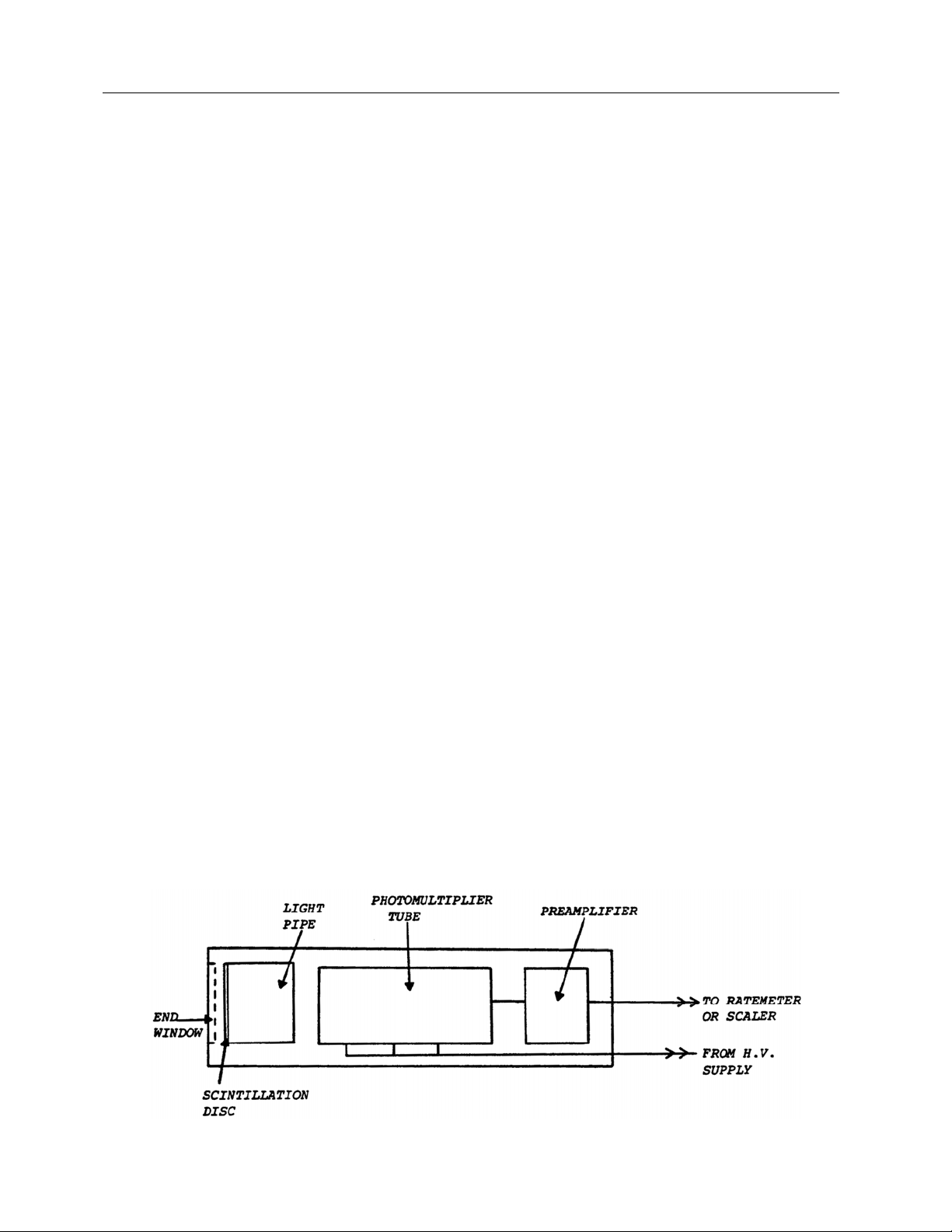
The Victoreen beta scintillation detector is shown in block diagram form in Figure 1-1. The detector
consists of a scintillation disc, a photomultiplier tube, a preamplifier assembly, and various interconnecting
cables connecting the detector, readout, and the detector power supply that is located at the ratemeter or
scaler module.
Figure 1-1. Block Diagram, 943 Series Beta Detector
1-2
Page 7

Introduction
Functional Description
Beta particles that have enough energy to penetrate the end window and impinge upon the disc will
produce light pulses, proportional to the energy deposited in the disc. The disc is thin so that gamma rays
will not have a high incidence of interaction with the disc. This yields a high rejection of gamma rays while
still possessing good sensitivity to beta particles.
A photomultiplier tube, optically coupled to the scintillator disc, detects visible light emitted from the disc
and converts this light to pulses of electrical energy whose voltage is proportional to the energy deposited
by the beta particle. The electrical pulse is sent to a preamplifier in the detector housing.
The preamplifier circuit amplifies the pulses received from the photomultiplier tube/crystal assembly,
providing a fixed gain of six (6). The current drive output of the preamplifier circuit will drive a 50-ohm
transmission line up to 1500 feet without degradation of the signal.
Should a very high intensity beta source be detected, the photomultiplier tube may become saturated.
That is, visible light from successive photon collisions within the scintillation disc may occur so often that
they are essentially continuous. This would have the effect of holding the output voltage of the
preamplifier at a relatively constant output voltage. Since the readout is designed to count pulses that
represent individual beta particle collisions, a high intensity beta signal could be interpreted as a low or no
radiation condition. An anti-jam circuit must be provided in the ratemeter or scaler to which the detector is
connected to prevent misinterpretation of the existing radiation field.
1
1.5 Receiving Inspection
The single channel analyzer board can be supplied independently or as a component of a UDR. Once the
SCA board has been received, unpack it from the shipping carton and inspect for damage.
1.6 Storage
Storage of Victoreen instruments shall comply with level B storage requirements as outlined in ANSI
N45.2.2 (1972) Section 6.1.2(.2). The storage area shall comply with ANSI N45.2.2 (1972) Section 6.2
Storage Area,
Level B components shall be stored within a fire resistant, tear resistant, weather tight, well-ventilated
building or equivalent enclosure.
Storage of Victoreen instruments must comply with the following considerations.
1.6.1 Control of Items in Storage
Inspection and examination of items in storage shall be in accordance with ANSI N45.2.2 (1972) Section
6.4.1. Requirements for proper storage shall be documented, and written procedures or instructions shall
be established.
1.6.2 In Case of Fire
Post-fire evaluation shall be in accordance with ANSI N45.2.2 (1972) Section 6.4.3.
Paragraphs 6.2.1 through 6.2.5. Housekeeping shall conform to ANSI N45.2.3 (1972).
1.6.3 Removal from Storage
Removal of items from storage shall be in accordance with ANSI N45.2.2 (1972) Sections 6.5 and 6.6.
1-3
Page 8

Victoreen 943-25, 943-26
Operators Manual
1.7 Procedures, Warnings, and Cautions
The equipment described in this manual is intended to be used for the detection and measurement of
ionizing radiation. It should be used only by persons who have been trained in the proper interpretation of
its readings and the appropriate safety procedures to be followed in the presence of radiation.
Although the equipment described in this manual is designed and manufactured in compliance with all
applicable safety standards, certain hazards are inherent in the use of electronic and radiometric
equipment.
WARNINGS and CAUTIONS are presented throughout this document to alert the user to potentially
hazardous situations. A WARNING is a precautionary message preceding an operation that has the
potential to cause personal injury or death. A CAUTION is a precautionary message preceding an
operation that has the potential to cause permanent damage to the equipment and/or loss of data.
Failure to comply with WARNINGS and CAUTIONS is at the user’s own risk and is sufficient cause to
terminate the warranty agreement between Fluke Biomedical and the customer.
Adequate warnings are included in this manual and on the product itself to cover hazards that may be
encountered in normal use and servicing of this equipment. No other procedures are warranted by Fluke
Biomedical. It shall be the owner’s or user’s responsibility to see to it that the procedures described here
are meticulously followed, and especially that WARNINGS and CAUTIONS are heeded. Failure on the
part of the owner or user in any way to follow the prescribed procedures shall absolve Fluke Biomedical
and its agents from any resulting liability.
Indicated battery and other operational tests must be performed prior to each use to assure that the
instrument is functioning properly. If applicable, failure to conduct periodic performance tests in
accordance with ANSI N323-1978 (R1983) Radiation Protection Instrumentation Test and Calibration,
paragraphs 4.6 and 5.4, and to keep records thereof in accordance with paragraph 4.5 of the same
standard, could result in erroneous readings or potential danger. ANSI N323-1978 becomes, by this
reference, a part of this operating procedure.
1-4
Page 9

2.1 Installation
Operation
Installation
2
Section 2
Operation
Do not apply voltage to the detector if the
mylar/titanium cover is not on the disc. Even slight
pinholes In the cover could admit enough light to
seriously damage the detector. Failure to observe
this precaution may destroy instrument calibration,
or may even cause destruction of the instrument
itself.
Install the detector into the sampler housing (refer to the sampler manual for specific mounting details).
Before connecting the detector to its readout, be sure channel power is turned off, and the high voltage
potentiometer is at the lowest setting.
On digital systems, the power should be turned off
before the detector cabling is connected to avoid a
surge that might destroy electronic components.
This is good practice with all systems, digital and
analog.
Connect the appropriate cables between the detector and the readout.
Do NOT exceed 2000 V to the detector under any
circumstances.
Operation of the detector during initial turn-on is dependent on whether the detector is supplied as part of
a radiation-monitoring channel or as a replacement part.
CAUTION
CAUTION
CAUTION
2.2 Detector Operation
Turn on channel power at the readout and slowly increase the high voltage to the value indicated on the
factory calibration sheet. This does not have to be an exact value because that value will be determined
during the calibration process. A two to four hour warm-up is recommended prior to commencing
calibration.
2-1
Page 10

Victoreen 943-25, 943-26
Operators Manual
2.3 Detector Operation - Replacement Parts
Turn on channel power at the readout and slowly increase the high voltage until a count rate of
approximately 100 cpm is achieved. This count rate assumes that the detector is in the open air and that
the discriminator threshold is set at 0.2 VDC in the readout. If the detector is placed within a lead shield,
the high voltage should be increased until a count rate of approximately 20 cpm is achieved. A two to four
hour warm-up is recommended prior to commencing calibration.
2-2
Page 11

Theory of Operation
Scintillator and Photomultiplier Tube
Section 3
3
Theory of Operation
3.1 Scintillator and Photomultiplier Tube
When beta particles enter the scintillation disc, pulses of light are emitted. The light pulses striking the
photocathode of the photomultiplier tube excite the electrons in the cathode to a high-energy state
causing them to escape from the surface of the cathode. The freed electrons are attracted by a voltage
potential to the first dynode of the photomultiplier tube. This starts a cascading effect where a charge is
passed from dynode to dynode, increasing in size at each stage until a shower of electrons is passed on
to the preamplifier.
3.2 Preamplifier
The schematic diagram for the preamplifier is located in Appendix A. The preamplifier provides
amplification of the output from the photomultiplier tube and cable driving capabilities. Negative pulses
derived from the photomultiplier tube are applied to the input of the preamplifier. Operational amplifier Z1
is configured as a non-inverting amplifier with a gain of approximately six (ratio of R6 + R7/R6). The
amplified pulses are coupled to transistors Q1 and Q2.
Resistor R11 allows impedance matching of the preamplifier to the 50-ohm transmission line connected to
the readout. The non-inverting input of Z1 (pin 3) is biased at +10 VDC potential. This enables the
operational amplifier, in conjunction with transistor Q1 and Q2, to drive 1500 feet of cable and produce a
6 V pulse at the readout
.
3-1
Page 12

Victoreen 943-25, 943-26
Operators Manual
(Blank page)
Page 13

Maintenance, Calibration, and Troubleshooting
Maintenance
Section 4
Maintenance, Calibration, and Troubleshooting
4.1 Maintenance
There is no periodic maintenance required for the detector. The following assembly/disassembly
procedure is to be used if the detector requires repair. Refer to Section 4.5, Troubleshooting, for the
troubleshooting procedure.
4.1.1 Detector Disassembly
Refer to the assembly drawings in Appendix A.
1. Remove the four screws from the base of the detector (connector end).
2. Take the assembly out using a pair of needle nose pliers, ensuring that it does not rotate during
removal.
The photomultiplier tube may separate from the
socket and remain within the detector sleeve. If this
occurs, pliers may be applied to the keyed plastic
base extrusion of the tube and carefully pulled from
within the detector sleeve with moderate vertical
force.
3. The photomultiplier tube can be completely removed from its socket by disconnecting the tube
shield wire.
NOTE
4
4.1.2 Detector Assembly
Refer to the assembly drawings in Appendix A.
1. Make sure the photomultiplier tube face (glass) is free of dust, fingerprints, etc. The tube can be
cleaned with methyl alcohol.
2. Lubricate the o-ring, located at the detector base, with a light consistency grease using P/N MSJ-
3306.
3. Connect the photomultiplier tube shield wire.
Rotating the assembly when fully installed inside
the detector sleeve will damage the interface
coupling. Align the base plate screw holes with the
sleeve holes prior to full Insertion of the assembly
into the sleeve.
4. Place the detector assembly inside the detector sleeve and press the baseplate into the sleeve,
aligning the four screw holes.
CAUTION
4-1
Page 14

Victoreen 943-25, 943-26
Operators Manual
5. Replace the four screws at the connector end of the detector.
4.2 Calibration
The beta scintillation detector is calibrated by adjusting the high voltage supply to the photomultiplier tube
(adjusting detector sensitivity to the photons that impinge on the scintillation disc).
This family of beta scintillation detectors essentially provides a linear output for all levels of beta radiation
until the disc starts to saturate. Setting the beta scintillation detector for the proper output count rate at
any point in its operating range assures an accurate measurement of any other point.
The beta scintillation detector is factory calibrated. It is usually shipped as part of a monitoring system and
the ratemeter or scaler module power supply is adjusted for an accurate reading over the entire operating
range.
After initial installation, at regular intervals after installation, if the detector is replaced, or if the power
supply output voltage changes, calibration should be repeated.
4.3 Calibration Where Calibration Data is Available
Calibration of the beta scintillation detector requires a standard button source of known beta activity for
which a known count rate is recorded in a standard geometry. The standard geometry (test fixture, P/N
844-36) is used to position the detector and button source with respect to each other (Figure 4-1). The
detector should be connected to the readout with all the cable that will be in place during normal
operation since the high voltage setting is slightly cable dependent. At the readout, set the discriminator
level to the level indicated on the data sheet (normally 0.2 VDC).
1. Insert the detector into the cavity provided in the standard geometry.
9O
2. Place the
3. The expected count rate for the button source should be determined. It is recorded on the
calibration data sheet. Correction must be made for decay. (The half-life of the source is 29.12
years.)
4. Adjust the high voltage power supply to the detector so that the net count rate corresponds to the
expected count rate calculated in Step 3.
Sr button source, blank side up (P/N 844-36-14), on the slide in the standard geometry.
NOTE
The net count rate is the indicated count rate minus
the background count rate.
5. The count rate will increase and decrease in conjunction with power supply voltage. If the high
voltage reaches 2000 VDC without achieving the necessary count rate, suspect a defect in the
detector, wiring, or readout device.
4-2
Page 15

Maintenance, Calibration, and Troubleshooting
Calibration Where Detector Is a Replacement Part
4.4 Calibration Where Detector Is a Replacement Part
Calibration of a replacement detector unit depends on the uniformity of response of the detector. The
replacement detector should have the same size scintillation disc as the original detector in the system.
The detector should be connected to the readout with all the cable that will be in place during normal
operation since the high voltage setting is slightly cable dependent. At the readout, set the discriminator
level to the level indicated on the data sheet (normally 0.2 VDC).
1. Insert the detector into the cavity provided in the standard geometry.
9O
2. Place the
(Figure 4-1).
3. The expected count rate for the button source should be determined. It is recorded on the
calibration data sheet. Correction must be made for decay. (The half-life of the source is 29.12
years.)
4. Adjust the high voltage power supply to the detector so that the net count rate corresponds to the
expected count rate calculated in Step 3.
5. The count rate will increase and decrease in conjunction with power supply voltage. If the high
voltage reaches 2000 VDC without achieving the necessary count rate, suspect a defect in the
detector, wiring, or readout device.
6. If more than one button source is available, measure all the button sources. The lowest activity
source should be used first. Record the high voltage values that reproduce the original count rates.
Average the high voltages to determine the best value for all the button sources.
Sr button source, blank side up (P/N 844-36-14), on the slide in the standard geometry
NOTE
The net count rate is the indicated count rate minus
the background count rate.
4
4.5 Troubleshooting
Troubleshooting is indicated for the detector when the measured output of the check source or some
other beta source shows a marked change in the count rate observed at the readout while high voltage
has remained constant.
Figure 4-1. Standard Geometry Drawer Inverted to Show Recess for Beta Disk Sources
4-3
Page 16

Victoreen 943-25, 943-26
Operators Manual
4.6 Safety Related Detectors
If the fault is isolated to the detector, repair can be performed by a technician rated to Skill level II as
described in Section 1.3, Specifications.
Any fault that cannot be isolated to the detector must be in the wiring to the readout or in the readout
itself. Consult the appropriate standard manual for the readout purchased so that the troubleshooting
procedure for that readout can be used. Defective wiring is replaced using the schematic diagram and
Table 4-1 as a guide.
Table 4-1. Cable Connector Pin Out
Pin Function
A High Voltage
B High Voltage Shield
E +15 VDC Supply
G
F -15 VDC
C Signal (Negative Pulses)
D Signal Ground
Power (± 15 V) Ground
4.7 Commercial Detectors
If the fault has been isolated to the detector, the following procedure can be used to identify the faulty
component. The schematic diagram in Appendix A can be used as a guide. Recommended test
equipment is listed in Table 4-2.
4.7.1 Preliminary
1. Turn off channel power at the readout.
2. Disassemble the detector according to Section 4.1.1, Detector Disassembly.
3. Remove and inspect the photomultiplier tube for visible signs of damage (cracks, excessive
rattling).
Do not replace the photomultiplier tube until
troubleshooting has been completed and power is
disconnected.
CAUTION
4-4
Page 17

Maintenance, Calibration, and Troubleshooting
Commercial Detectors
Table 4-2. Recommended Test Equipment
Feature Specification
Pulse Generator (Square Wave)
Pulse
Rise Time
Pulse Width 1.0 microsecond (variable)
Output Impedance 50 ohms
Maximum Repetition Rate 2 MHz
Digital Voltmeter
Ranges
Accuracy
Input Impedance
Oscilloscope (Dual Trace)
Bandwidth 10 MHz @ 10 mV/div
Fastest Sweep Time < 10 Microseconds/div
Electrostatic Voltmeter
Range 0 to 2000 VDC
Precision
Input Impedance 10
Counter/Scaler
Maximum Count Rate 105 cps
Minimum Pulse Width for Counting 40 ns
Preset Counting Time 0.1,1.0, and 10 minutes
± 0.1 to 5 V variable (into a 50 ohm load)
≤ 30 ns
± 0 to 100 mV up to ± 0 to 1000 V (20%
overrange)
± 0.1% of input +1 digit
≥ 10 megohms
± 1%
12
ohms
4
4.7.2 Dynode Test Measurement
Preamplifier input is easily damaged. Ground pin 3
of Z1 before applying power and measuring
photomultiplier tube anode or dynode voltage.
1. Using an electrostatic voltmeter, measure the total DC resistance of the dynode string. The value
should be 9.67 megohms ± 15%. If no reading is obtained, check dynode resistor interstage
connections.
2. Connect the cable to the readout.
3. Turn on channel power and apply 900 V to the detector. Measure the anode resistor voltage (R13)
using an electrostatic voltmeter. The value should be 900 V.
4. Remove channel power.
CAUTION
4.7.3 Preamplifier Checkout
High voltage must be removed for this test.
1. Remove the grounding jumper from pin 3 of Z1.
2. Connect an oscilloscope to the input circuitry of the readout (50 ohms terminated).
4-5
Page 18

Victoreen 943-25, 943-26
Operators Manual
3. Turn on channel power.
4. Using a pulse generator, inject negative pulses of -0.50 V amplitude, one microsecond pulse
duration, at a frequency of 1 kHz to the node of R13 and C6 (+) and gnd (-).
5. Output pulses should be -1.6 V ± 20% amplitude. If pulses are not present, check Z1 and
associated circuitry.
If the preamplifier and dynode tests are positive, the detector malfunction is probably in the
photomultiplier tube. Remove all power, replace the photomultiplier tube and reassemble the detector
according to the procedure in Section 4.1.2.
4.8 Replacement Parts
Drawing Number Description
943-25 Beta Scintillation Detector, Mylar End Window,
943-26 1:1 Response Ratio
943-25A Beta Scintillation Detector, Mylar End Window,
943-26A 10:1 Response Ratio
943-25B Beta Scintillation Detector, Mylar End Window,
943-26B 100:1 Response Ratio
943-25T Beta Scintillation Detector, Titanium End Window,
943-26T 1:1 Response Ratio
943-25TA Beta Scintillation Detector, Titanium End Window,
943-26TB 10:1 Response Ratio
943-25TB Beta Scintillation Detector, Titanium End Window,
943-26TB 100:1 Response Ratio
NOTE
Refer to the individual assembly drawings for a
breakdown of individual components.
4-6
Page 19

Applicable Drawings
Applicable Drawings
A.1 Applicable Drawings
Detectors 943-25, 94-25T, 943-25A, 943-25B, 943-25TA, 943-25TB
Drawing Number
943-25-5 Beta Scintillation Detector Assembly
943-25T-5 Beta Scintillation Detector Assembly
843-25-10 Preamplifier Circuit Board Assembly
843-25-3 Detector Schematic
Description
Appendix
A
Appendix A
Detectors 943-26, 943-26T, 943-26A, 943-26B, 943-26TA, 943-26TB
Drawing Number Description
943-26-5 Beta Scintillation Detector Assembly
943-26T-5 Beta Scintillation Detector Assembly
A-1
Page 20

Fluke Biomedical
Radiation Management Services
6045 Cochran Road
Cleveland, Ohio 44139
440.498.2564
120 Andrews Road
Hicksville, New York 11801
516.870.0100
www.flukebiomedical.com/rms
 Loading...