

Page 1

Get more
done
Now includes the
NEW Fluke 922
Airflow Meter
HVAC/Indoor
Air Quality
Reference Guide
Volume 2, 2007
• Glossary
• Helpful tips
• Application notes
Page 2
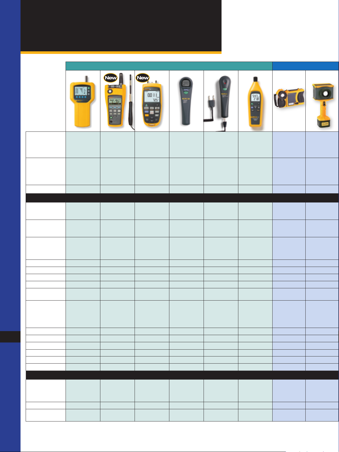
HVAC/Indoor Air Quality
Selection Guide
Air Composition Thermal Imaging IR Temperature TC Temperature Pressure HVAC Electrical Tools
Model 983
Particle
Counter
975
AirMeter
922
™
Airflow
Meter
CO-220
CO Detector
CO-210
CO Probe
(1)
Temperature
971
Humidity
TiR Series
Thermal
Imagers*
IR-InSight
Infrared
Imagers*
Meter
Description Measu re six
Page Number 4 6 8 9 9 10 11 12 14 15 18
Measurement s
Part icle size 0.3, 0.5, 1.0,
Temperature +40 °C
Air velocity 50 fpm to
CO
2
CO 500 ppm 0 to 999 ppm 0 to 1000 ppm
Optical resolution 12:1 10:1
Relative humidity 20 % to 90 % 10 % to 90 % 5 % to 95 %
Vacuum 76 cm Hg
particle sizes
simultaneously
2.0, 5.0,
10.0 µm
(104 ºF)
Measu re
temperat ure,
humidity, CO2, CO,
Velocity with one
tool
+50 °C
(122 °F)
3000 f pm,
0.25 m/sec to
15 m/sec
5000 ppm
Combines air
pressure, velocity
and flow into one
rugged, easy-to-
use meter
+50 °C
(122 °F)
250 fpm to
16,000 fpm,
1 m/sec to
80 m/sec
Quickly test
CO levels
Conveniently
measu re CO
with t his
DMM accessory
Measure humidity
faster, calculate
wet bulb and
dew point
temperatures
+60 ºC
(140 ºF)
Provides fast and
easy precision
temperat ure
measu rements
+600 °C
(1112 °F)
Low contrast
thermal
application
imager
+100 °C
(212 °F)
Pressure ± 4000 Pascals
Voltage ac/dc 600 V ac 600 V 600 V, 600 mV 1000 V
2
Current ac/dc 600 A/200 µA 600 µA 400 mA
Resistance
Frequency 50 kHz 100 k Hz
Capacitance 1000 µF 9999 µF 999 µF
Conductance
Data storage
Data logging 5000 readings 99 readings
Min/Max/Avg Yes/Yes/Yes Yes/Yes /Yes No/Yes/No Yes/Yes/Yes Yes/Yes/No No/Yes /No Yes/Yes/Yes Yes/Yes/No Yes/Yes/Yes Yes/Yes/No
Display Hold/
Auto (Touch) Hold
(1) Accessory for use with a digital multimeter with dc millivolt inputs.
(discrete),
25,000 readings
(continuous)
± 16 in H2O
± 400 mm H2O
± 40 mbar
± 0.6 PSI
99 readings 99 readings 500 readings
Yes/No Yes/ No Yes/No Yes/No Yes/No Yes/No Yes/ No No/No
Page 3
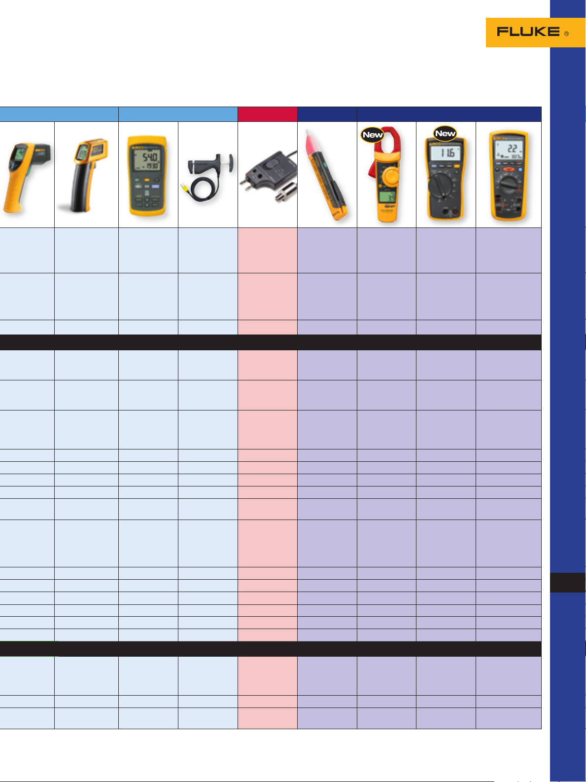
561
HVACPro
IR Thermo-
meter
Contact and
non-contact
temperat ure in
one
62
Mini IR Ther-
mometer
Best accuracy in
its class, perfect
introduction to IR
thermometers
54
TC Ther-
mometer
Dual-temperature
for ∆T across
fur naces and
coils
80PK-8
TC Clamp
DMM accessory
captures liquid
and suction line
temperat ures
18 19 20 21 22 23
PV350 Pres-
(1)
sure/Vac
DMM accessory
captures liquid
and suction line
pressure values
(1)
1AC II
VoltAlert
Voltage
Detector
Non-contact
voltage w ith
audio alarm
902
True-rms
HVAC Clamp
Meter
Desig ned for
HVAC, with
temperat ure, dc
microamps and
capacitance
116
HVAC
Multimeter
Basic DMM
built for
HVAC
technicians
1587
Insulation
Multimeter
Insulation tester
and tr ue-rms
digital
multimeter
in one
+550 °C
(1022 ºF)
+500 ºC
(932 ºF)
+1767 ºC
(3212 ºF)
J, K, T, E, N, R, S
+149 °C
(300 ºF)
(406.7 in H20)
3447 kPa
(499.9 psi)
+400 °C
(752 °F)
K
9999 W 40 MW 50 MW
+400 °C
(752 ºF)
K
+537 °C
(998 º F)
K
3
*Multiple models available to suit your specific needs. See www.fluke.com for more information.
Page 4
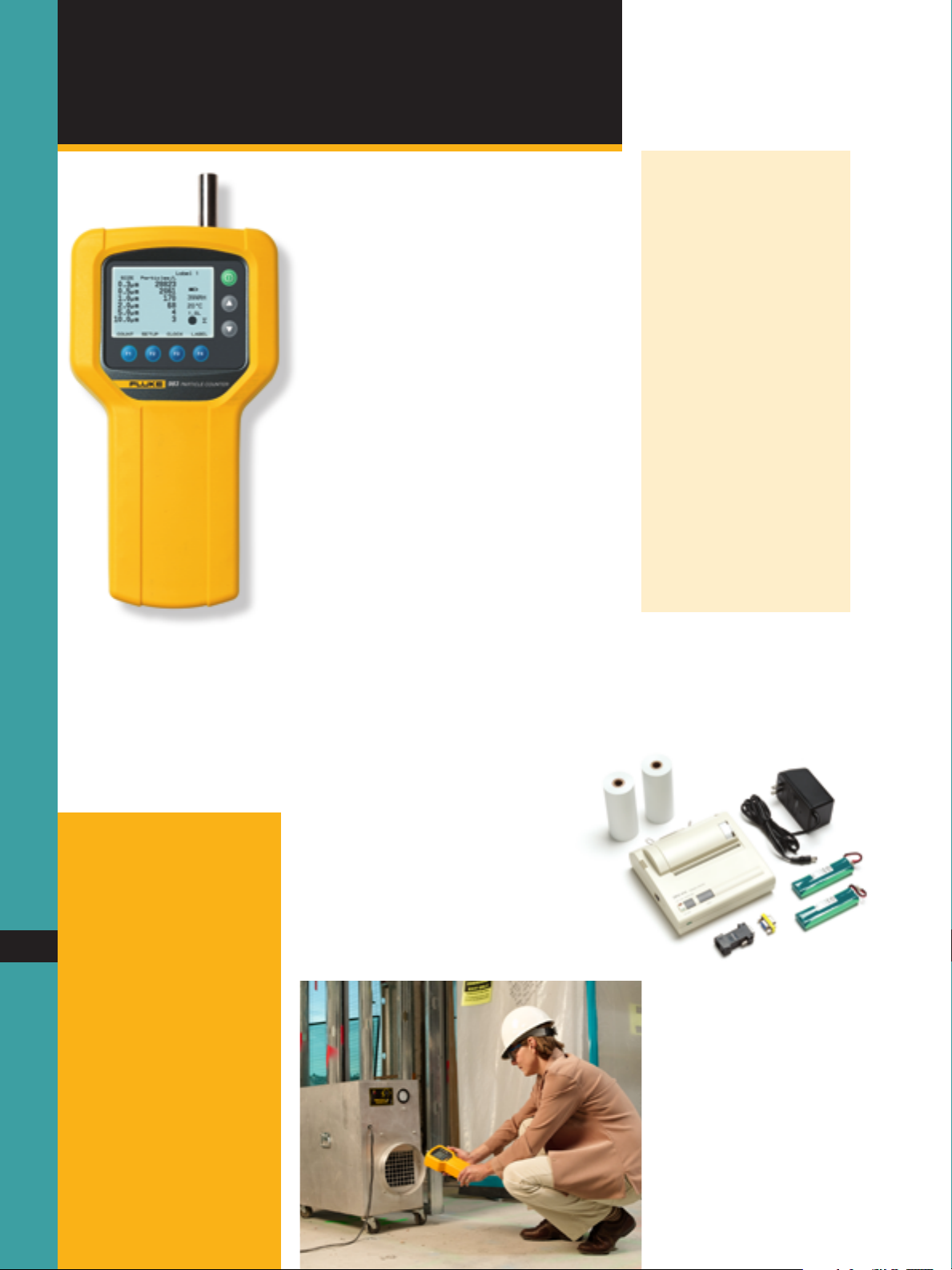
Air Composition
Particle Counter
Fluke 983 Particle Counter
Troubleshoot and maintain
indoor air quality.
The new Fluke 983 Particle Counter, the preferred choice for HVAC and IAQ professionals,
measures temperature and relative humidity as
well as particle size. With expanded data
logging and six-channel particle size display,
the Fluke 983 allows users to run more tests
quickly, with less time spent cycling through
screens to obtain data. The Fluke 983 is lightweight and easy to use in any position, with a
comfortable hand strap and rugged holster.
Use it to:
Monitor HVAC filter efficiency
•
Assess duct cleanliness per NADCA ACR
•
2006 Particle Profiling procedure
Verify compliance to cleanroom standards
•
Locate particle sources and report back on
•
post-remediation conditions
The Fluke 983 Particle Counter offers:
Selectable sample time, count data, and
•
programmable delay
User-defined sample size (cubic feet or liters)
•
and temperature measurements (°C or °F)
Data displayed in totalize or concentration
•
modes
Logged samples include date, time, particle
•
counts, sample volume, temperature, and
relative humidity
Quick Tips
Particle counts
Particle counts vary according
to a number of factors such
as location, time of year, and
occupants. When taking particle counts, always establish
an outside baseline reading to
compare indoor particle levels
against. Ideally, indoor particle
levels will be less then outdoor
levels.
Filter bypass
When testing for filter bypass,
take particle counts before
and after sealing the edges of
the filter with duct tape. This
will provide an indication of
how much particulate matter is
bypassing the filter due to poor
fitment or compromised sealing
surfaces.
Fluke TP120 Thermal Printer
Kit includes:
Thermal printer
•
(2) rolls paper
•
Battery pack
•
Serial adapter
•
Ordering information
Fluke-983 Particle
Counter
Includes: Certificate of
Calibration (NIST), Windows-
4
compatible software download
utility, DB9 to RS-232 adapter
and cable, Isokinetic probe, zero
count filter, high purity tubing,
1
/8 in. hose barb adapter,
power supply, hard molded
plastic case, and users manual
Page 5
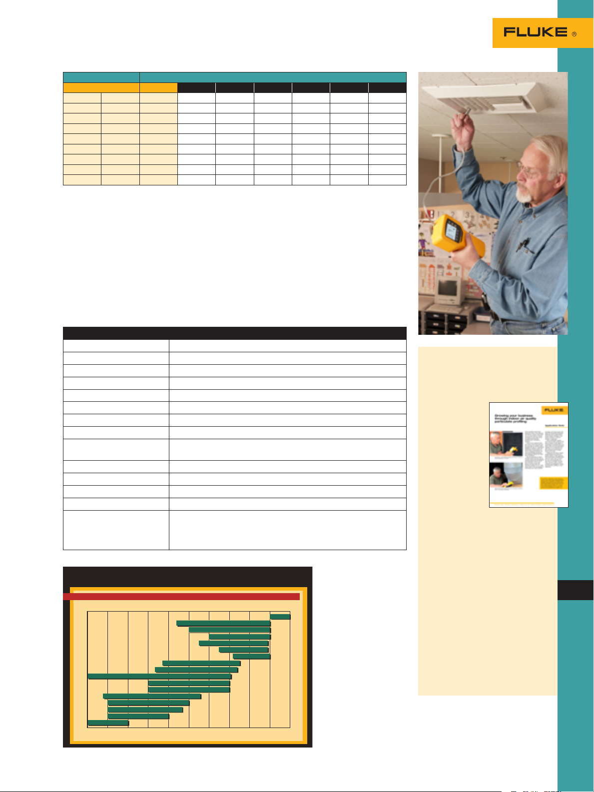
Class Number of Particles per Cubic Meter by Micrometer Size
.OTE-ICRONX-ETERS≈ X)NCHES)NCHES
!NGSTROMUNIT
-ETERS-ICROMETERS-ICRONS
0ARTICLE#HAR T
0ARTICLE3IZE
-ICROMETERS-ICRONS
2ELATIVESIZEOFCOMMONMATERIALS
!NGSTROM5NITS
(EAVY$UST
&LY!SH
3ETTLING$UST
#EMENT$UST
-OLD3PORES
0OLLEN
(UMAN(AIR
#OOKING/IL3MOKE'REASE
"ACTERIA
3USPENDED!TMOSPHERIC$UST
(OME$UST
!NIMAL$ANDER
3MOG
4OBACCO3MOKE
3OOT
#ARBON"LACK0HOTOCOPIER
6IRUSES
Federal Std 209E ISO 14644 0.1 µm 0.2 µm 0.3 µm 0.5 µm 1 µm 5 µm
ISO 1 10 2
ISO 2 100 24 10 4
1 M1.5 ISO 3 1,000 237 102 35 8
10 M2.5 ISO 4 10,000 2,370 1,020 352 83
100 M3.5 ISO 5 100,000 23,700 10,200 3,520 832 29
1,000 M4.5 ISO 6 1,000,000 237,000 102,000 35,200 8,320 293
10,000 M5.5 ISO 7 352,000 83,200 2,930
100,000 M6.5 ISO 8 3,520,000 832,000 29,300
ISO 9 35,200,000 8,320,000 293,000
Summary of cleanroom classification standards
Cleanroom particle concentrations
The above table presents airborne
particle limits for cleanroom applications per Federal Std 209E and ISO
14644 standards. The number of
particles per cubic meter represent the
maximum concentration limits for particles equal to and larger than the size
tested for. For example, an ISO class
5 cleanroom certified at 0.3 microns
should have no more than 10,200
particles 0.3 microns and larger. There
are other requirements regarding
sample volumes, locations and procedures that must be adhered to. Refer to
the applicable cleanroom standard for
more information.
Summary specifications
Feature Description
6 size channels 0.3, 0.5, 1.0, 2.0, 5.0, 10.0 µm
Flow rate 0.1 cfm (2.83 L/min) controlled by internal pump
Count modes Concentration, totalize, audio
Counting efficiency 50 % @ 0.3 µm; 100 % for particles > 0.45 µm (per JIS B9921:1997)
Zero count 1 count /5 minute (JIS B9921:1997)
Coincidence loss 5 % at 2,000,000 particles per ft
Relative humidity ± 7 %, 20 % to 90 % non-condensing
Temperature ± 3 °C, 10 °C to 40 °C (50 °F to 104 °F)
Data storage 5000 sample records (rotating buffer) of date, time, counts, relative
Alarms Counts, low battery, sensor fail
Delay time 0 to 24 hours
Sample inlet Isokinetic probe
Interface RS-232 and RS-485 via RJ-45
Environmental Operating: 10 °C to 40 °C (50 °F to 104 °F), 20 % to 90 % relative
humidity, temperat ure, sample volumes, alarms, and label
humidity, non-condensing
Storage: -10 °C to 50 °C (14 °F to 122 °F), up to 90 % relative humidity,
non-condensing
Growing your business
through indoor air quality
particulate profiling
You’ve probably heard mold referred to
as the “new asbestos”
for HVAC/R.
Concern about
mold and its health
effects is driving consumers to
have their indoor
air quality (IAQ)
situation assessed
and, if necessary,
repaired.
If you’re the
contractor they
call, keep in mind
that mold isn’t the
only issue to consider when assessing the IAQ of a commercial building
or residence. Many different kinds of
particulates in a work or living environment can cause Sick Building Syndrome
and aggravate allergy and respiratory
conditions. Read a detailed application
note on www.fluke.com/iaq
Common airborne particles and their sizes.
For more product information and detailed specifications, go to www.fluke.com
5
Page 6
Air Composition
Fluke 975V
Ordering information
Fluke-975 AirMeter
Fluke-975V AirMeter
with Velocity
Includes: AA alkaline batteries
(3), users manual (with safety
information), calibration cap,
hard carrying case, FlukeView™
6
Forms software, power
adapter, international power
plugs and air velocity probe
(Fluke 975V only)
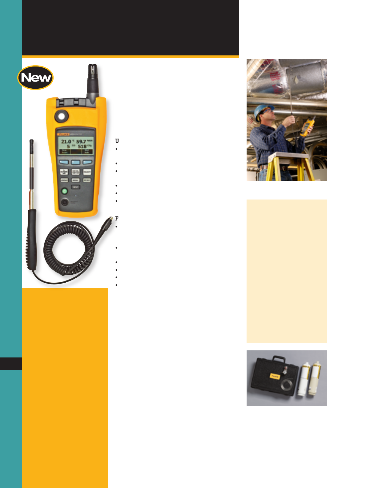
AirMeter
™
New! Fluke 975 AirMeter™
Five powerful tools in one!
The new Fluke 975 AirMeter test tool raises
indoor air monitoring to the next level by
combining five powerful tools in one rugged
and easy-to-use handheld tool by measuring
temperature, humidity, velocity, CO2 and CO.
The Fluke 975 AirMeter test tool makes indoor
air quality testing easier and faster.
Use it to:
Optimize HVAC system operation and
•
manage energy costs
Respond to comfort-related occupant calls
•
Verify the operation of building HVAC control
•
systems
Monitor air flow and velocity (975V only)
•
Test for dangerous carbon monoxide leaks
•
Monitor and data log conditions, then
•
download for further analysis
Features include:
Simultaneously measures, logs, and displays
•
temperature, humidity, CO2, and CO on a
bright, backlit LCD display
One-touch air flow and velocity with
•
available probe (975V only)
Wet bulb and dew point temperature
•
% of outside air calculation
•
CO2 and CO field calibration feature
•
Self-test function at startup
•
Auto-backlight
•
Automatically compensates for barometric
•
pressure changes
Min/Max/Average on all measured and
•
calculated readings
Multi-language user interface
•
Metric or standard units
•
Audible and visual threshold alarms
•
Extensive discrete or continuous data
•
logging capacity, downloadable to PC
via USB interface
Keypad lock for security
•
Included FlukeView Forms® software
•
Using the velocity probe to check velocity
within a duct.
Quick Tips
Frequent Calibration is Key
Frequent calibration of gas
sensors is key to maintaining
the accuracy and performance
of the device. Both CO2 and
CO sensors can exhibit tendencies to drift over time due to
environmental factors such as
temperature, humidity, and
pressure.
Fluke recommends monthly
calibration of the CO sensor,
and an annual calibration for
CO2 for optimum performance.
Optional accessories
Fluke-975CK AirMeter
Calibration Kit
Includes: Zeroing and span gas,
tubing, regulator, hard carrying
case
Fluke-975VP AirMeter
Velocity Probe
Fluke-975CK Calibration Kit
Page 7
Summary specifications
Odor (3%)
Too Dry (4%)
Too Humid (1%)
Noisy (3%)
Drafty (1%)
Too Hot (29%)
Too Cold (47%)
Smell (12%)
Adapted from: Federspiel, C.C. 1998. Statistical Analysis of Unsolicited Thermal
Sensation Complaints in Commercial Buildings. ASHRAE Transactions 104(1): 4, 8.
Application Note
Measuring air velocity with
the Fluke 975 AirMeter:
Using the velocity probe
Fro m t h e F lu k e D ig i ta l L i br ar y @ w ww .f l uk e .c o m/ l ib ra r y
Air velocity is a key parameter in evaluating airflow system performance. As part of basic testing, adjusting
and balancing of HVAC air distribution systems, most
HVAC technicians now use an anemometer to measure air velocity at grilles-registers-diffusers, within a
duct, or in open spaces.
Anemometers are typically very accurate tools,
especially at low velocities, but they must compensate
for air temperature, absolute pressure, and ambient
absolute pressure. The Fluke 975 AirMeter tool has an
accessory velocity probe that uses a thermal anemometer to measure air velocity. A temperature sensor in
the probe tip compensates for air temperature, a sensor in the meter reads absolute pressure, and ambient
absolute pressure is determined upon meter initialization. For users who prefer to calculate their own compensation factors, the meter will also display air velocity
or volume at standard conditions.
This application note describes how to take accurate
air volume measurements within a duct, air measurements at grilles-registers-diffusers, and other locations.
Air volumes within a duct
The ultimate goal of any duct
system is to move the required
air volume, while keeping all
other factors within acceptable
limits, and to deliver it in quantities and patterns that serve the
intended purpose: heating, cooling, ventilating, exhausting, mixing, humidifying, dehumidifying,
or otherwise conditioning the air
within a space. Velocity within
a duct is determined not only
by application, but also by how
the duct is designed. Key design
factors include: The level of
available static pressure that can
be overcome by the fan due to
friction losses and pressure drops
of devices within the air stream;
the cost of duct work; the space
available for duct work; and
acceptable noise levels.
To determine the air volume
delivered to all downstream terminal devices, technicians use a
duct traverse. Duct traverses can
determine air volume in any duct
by multiplying average velocity
readings by the inside area of
the duct. Traverses in main ducts
measure total system air volume,
which is critical to HVAC system
performance, efficiency, and even
life expectancy. The difference
in air volumes between the main
supply duct traverse and the
main return duct traverse results
in outdoor air volume. A traverse
in run-outs is the most accurate
way to determine the air volume
delivered by the terminal device
(grille-register-diffuser). A traverse in exhaust ducts reveals
exhaust air volume.
Measuring air velocity in a duct.
Feature Range Display
resolution
Measured specifications
Temperature -5 °F to 122 °F
(-20 °C to 50 °C)
Relative humidity 10 % to 90 % RH
0.1 °F
(0.1 °C)
1 % ± 2 % RH
non-condensing
Air velocity 50 fpm to 3000 f pm
0.25 m/sec to
1 fpm
0.001 m/sec
15 m/sec
CO
2
0 to 5000 ppm 1 ppm Warm up t ime 1 min (5 minutes for full
CO 0 to 500 ppm 1 ppm ± 5 % or ± 3 ppm, whichever is greater,
Calculated specifications
Dew point
temperat ure
Wet bulb
temperat ure
Volume flow rate
(in a duct)
% outside air
-44 °C to 50 °C
0.1 °C (0.1 °F) ± 1 °C when temp: -20 °C to 50 °C
(-47 °F to 122 °F)
-16 °C to 50 °C
0.1 °C (0.1 °F) ± 1.2 °C when RH: 20 % to 90 %
(3 °F to 122 °F)
0.01 M3/min
(1 cfm)
0 to 100 % 0.1 % N/A
(based on
temperat ure)
% outside air
0 to 100 % 0.1 % N/A
(based on CO2)
Accu racy
± 0.9 °C/± 1.62 °F from 40 °C to 50 °C
± 0.5 °C/± 1.00 °F from 5 °C to 40 °C
± 1.1 °C/± 1.98 °F from -20 °C to 5 °C
(10 % RH to 90 % RH )
± 4 % or 4 fpm*
± 4 % or 0.02 m/sec* whichever is
greater
*Accuracy specification only valid for
velocity readi ngs above 50 fpm or
0.25 m/sec.
specification)
2.75 % + 75 ppm
@ 20 °C and 50 % R H
RH: 40 % to 90 %
± 2 °C when temp: -20 °C to 50 °C
RH: 20 % to 4 0 %
± 4 °C when RH: 10 % to 20 %
temp: -20 °C to 50 °C
± 2.1 °C when RH: 10 % to 20 %
N/A
The volume flow calculation will be a
simple average of the data points times
the duct area
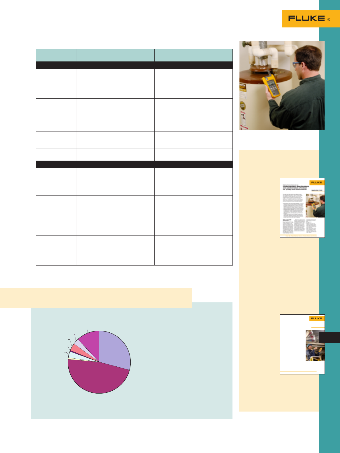
Technician using the 975 AirMeter to
check for carbon monoxide leaks.
Making the numbers add up:
Understanding specifications
and performance of indoor air
quality test instruments
Air quality test
instruments must
deliver accurate
and verifiable performance, both to
ensure precise and
reliable air quality
diagnosis, and to
provide credible
answers if results
or procedures are
challenged. The
air quality professional’s reputation
depends on the quality and performance of the test tools in use, as well
as on their understanding of instrument
specifications, technologies, applications
and maintenance.
Read more about indoor air parameters, the technology to measure them,
and the importance of calibration to
optimize performance and promote
safety. Read a detailed application note
on www.fluke.com/iaq
Did You Know?
Common occupant complaints
For more product information and detailed specifications, go to www.fluke.com
Just the facts:
77 % of occupant
•
complaints are due to
thermal conditions
Technicians will take
•
from 1.5 to 2 hours to
respond to and diagnose those complaints
Fluke 975 helps technicians diagnose conditions
quickly and with fewer
tools. Do more. Carry less.
Measuring air velocity with the
Fluke 975 Airmeter using the
velocity probes
Air velocity is a key
parameter in evaluating airflow system performance.
As part of basic
testing, adjusting
and balancing of
HVAC air distribution systems, technicians measure air
velocity at grilles/
registers/diffusers
within a duct or in
open space.
Read more about effectively measuring airflow and other IAQ and HVAC
issues on www.fluke.com/iaq
7
Page 8
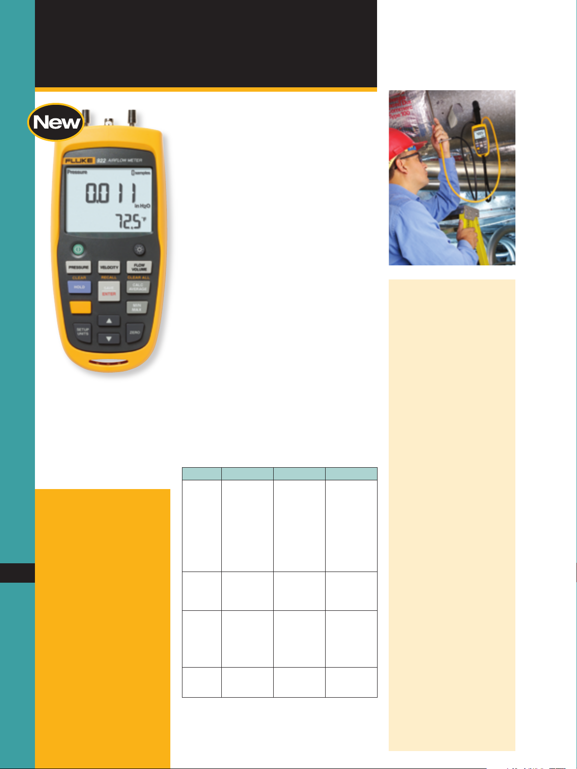
Ordering information
Fluke-922 Airflow Meter
Includes: Two rubber hoses,
four AA batteries 1.5 V alkaline,
users manual and soft carrying
case
8
Fluke-922/Kit
Includes: Fluke 922 Airflow
Meter, 12 inch Pitot tube, two
rubber hoses, TPak magnetic
strip, TPak strap, 9 inches, TPak
latch tab, four AA batteries 1.5
V alkaline, users manual, hard
carrying case
Optional accessories
PT12 12” Pitot Tube
Fluke-TPAK ToolPak™
Air Composition
Airflow Meter
New! Fluke 922 Airflow Meter
Today’s HVAC technicians want a simple
solution for diagnosing ventilation issues. The
Fluke 922 makes airflow measurements easy
by combining pressure, air flow, and velocity
into a single, rugged meter.
Use the Fluke 922 to:
Ensure proper air flow balance
•
Monitor pressure to extend HVAC
•
component life
Promote good indoor air quality
•
Maintain a comfortable environment
•
Features include:
Powerful meter provides differential and
•
static pressure, air velocity and flow
readings
Rugged case and holster for real-world use
•
Easy to use without sacrificing performance
•
User-defined duct shape and size for maxi-
•
mum utility
Convenient colored hoses helps users prop-
•
erly diagnose pressure readings
Bright, backlit display for less than ideal
•
environments
Min/Max/Average/Hold functions for easy
•
data analysis
Auto power off saves battery life
•
Operating specifications
Feature Range Resolution Accuracy
Air
Pressure
Air
Velocity
Air Flow
(Volume)
Temperature
± 4000
Pasca ls
± 16 in H2O
± 400 mm
H2O
± 40 mbar
± 0.6 PSI
250 to
16,000 fpm
1 to 80 m/s
0 to
99,999 cfm
0 to
99,999 m3/hr
0 to
99,999 l /s
0 °C to 50 °C
32 °F to 122
°F
1 Pasca l
0.001 in H2O
0.1 mm H2O
0.01 mbar
0.0001 PSI
1 fpm
0.001 m/s
1 cfm
1 m3/hr
1 l/s
± 1 % + 2 °C
± 1 % + 4 °F
± 1 % + 1
Pasca l
± 1 % + 0.01
in H2O
± 1 % + 0.1
mm H2O
± 1 % + 0.01
mbar
± 1 % +
0.0001 PSI
± 2.5 % of
reading at
2000 fpm
(10.00 m/s)
Accuracy is a
function of
velocity and
duct si ze
0.1 °C
0.1 °F
Quick Tips
How HVAC airflow impacts
operating costs
Dirty coils, fans, and filters
will increase static pressure
by reducing airflow, causing HVAC equipment to work
harder to meet occupant loads
and increasing energy costs.
With HVAC energy costs often
comprising over 50 % of
the total energy bill, tighter
monitoring and control of
HVAC airflow can have a direct
impact on the bottom line.
In a study1 on coil clean-
•
ing and energy savings in
a New York City high rise,
pressure monitoring and
visual inspection led to
restoration of the coils and
components. The restoration resulted in a 14 %
decrease in pressure drop
across the coils, a 25 %
increase in the coil’s thermal efficiency, and energy
savings of up to $40,000 in
the first year.
EPA studies2 show that a 15
•
cfm airflow differential can
impact annual HVAC energy
costs by up to 8 % depending upon the HVAC system
and variations in climate.
1
Baker, Robert G.; Montgomery,
Ross D. “Coil Cleaning and its
Resultant Energy Savings and
Maintenance Enhancements.”
Indoor Air Quality Conference
Proceedings, 2006:22-27.
2
“Energy Cost and IAQ Perfor-
mance of Ventilation Systems
and Controls, Project Report #4.”
United States Environmental
Protection
Agency, January 2000:10.
Page 9
Air Composition
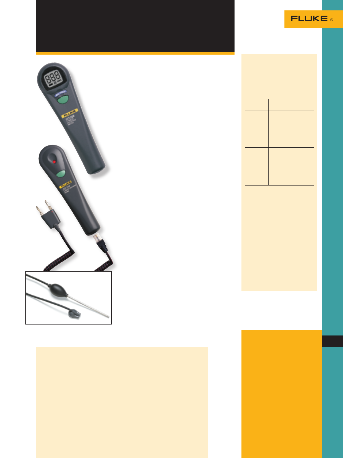
CO Detector and Probe
Fluke CO-220 Carbon
Monoxide Meter
Standalone CO meter that does not require
•
a digital multimeter
Large backlit LCD displays CO levels from
•
0 to 999 ppm, with a resolution of 1 ppm and
accuracy of ± 5 %
Beeper triggers with increasing frequency
•
as CO levels rise
MAX hold function stores and displays the
•
maximum CO level
Automatic sensor zeroing and self-test upon
•
startup
Fluke CO-210 Carbon
Monoxide Probe
Used as an accessory to a digital multimeter
•
with dc millivolt inputs
Displays CO level readings from 0 to
•
1000 ppm, with a resolution of 1 ppm and
accuracy of ± 5 %
Also used as a standalone device with an
•
LED indicator and beeper that triggers with
increasing frequency as CO levels rise
Fluke CO-205 Aspirator Kit
The CO-205 flue gas sampling accessory kit
contains all the components necessary to
provide a clean sample for the Fluke family of
gas measuring devices.
The CO-205 accessory kit includes:
Stainless steel sampling tube
•
Industrial-grade hand operated aspirator
•
to draw flue sample
Easily replaceable particulate filter
•
Specially designed nose cap for connection
•
to the Fluke CO-210/220
What is carbon
monoxide (CO)?
Carbon monoxide (CO) is a colorless, odorless, poisonous gas
with potentially serious health
consequences given adequate
exposure.
CO levels Exposure
70 to
100 ppm
150 to
300 ppm
400 and
higher
ppm
Treatment options
Get victim to fresh air
immediately.
If you can’t get victim out of the
building open all windows and
doors.
Take victim to a hospital
emergency room for a carbon
monoxide blood test.
symptoms
Flu or food
poisoning like:
Mild headaches
Sore eyes
Runny nose
Mild nausea
Shortness of breath
Dizziness
Headaches
Drowsiness
Vomiting
Unconsciousness
Brain damage
Death
How many people are unintentionally poisoned by CO?
Every year, over 200 people in the
United States die from CO produced
by fuel-burning appliances (furnaces, ranges, water heaters, room
heaters). Others die from CO produced while burning charcoal inside
a home, garage, vehicle or tent. Still
others die from CO produced by cars
left running in attached garages.
Several thousand people go to hospital emergency rooms for treatment
for CO poisoning.
For more product information and detailed specifications, go to www.fluke.com
What is the permissible
exposure to CO?
The current Occupational Safety
and Health Administration (OSHA)
permissible exposure limit (PEL) for
carbon monoxide is 50 ppm over an
8-hour time period.
Ordering information
Fluke-CO-220 Carbon
Monoxide Meter
Includes: Soft carrying case,
battery and instruction sheet
Fluke-CO-210 Carbon
Monoxide Probe
Includes: Soft carrying case,
battery and instruction sheet
Fluke-CO-205
Aspirator Kit
Includes: Instruction sheet
9
Page 10
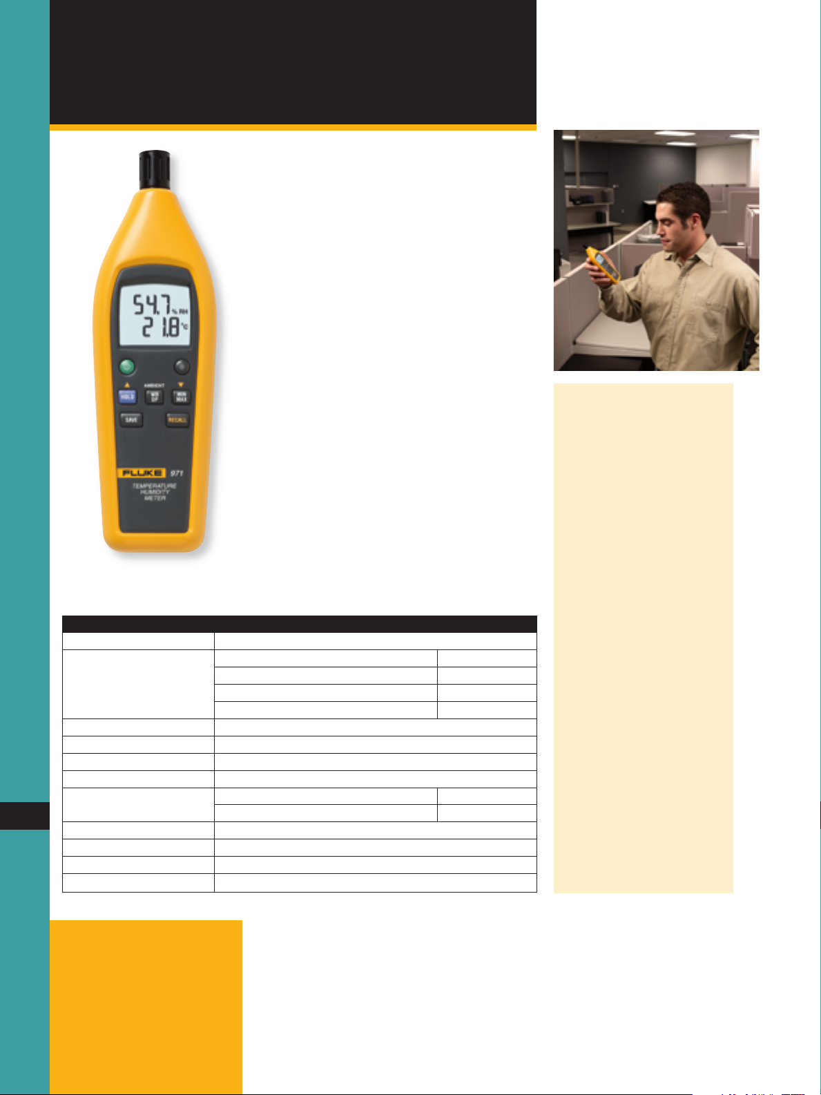
Air Composition
Temperature Humidity Meter
Fluke 971 Temperature
Humidity Meter
The rugged new answer to
humidity and temperature in
your building.
Quickly take accurate humidity and temperature readings. Temperature and humidity are
two important factors in maintaining optimal
comfort levels and good indoor air quality.
The Fluke 971 is rugged, lightweight, and easy
to hold.
Use it to:
Monitor indoor comfort conditions and
•
respond to “hot/cold” calls from occupants
Matching HVAC system capacity to the load
•
Promote good indoor air quality
•
Key features:
Fast-settling humidity sensor
•
Instant wet bulb and dewpoint temperature
•
calculations
Bright backlit display
•
Rugged holster and protective twist-open
•
sensor cover
Convenient Min/Max feature and data
•
storage capacity
Summary specifications
Feature
Temperature range -20 °C to 60 °C ( -4 °F to 140 °F)
Temperature accuracy 0 °C to 45 °C ± 0.5 °C
-20 °C to 0 °C and 45 °C to 60 °C ± 1.0 °C
32 °F to 113 °F ± 1.0 °F
-4 °F to 32 °F and 113 °F to 140 °F ± 2.0 °F
Resolution 0.1 °C / 0.1 °F
Temperature update rate 500 ms
Temperature sensor type NTC
Relative humidity range 5 % to 95 % R.H.
Relative humidity accuracy 10 % to 90 % R.H. @ 23 °C (73.4 °F) ± 2.5 % R.H.
10
Resolution 0.1 % R.H.
Response time ( humidity) For 90 % of total range—60 sec. with 1 m/s air movement
Humidity sensor Electronic capacitance polymer fi lm sensor
Data storage 99 points
<10 %, > 90 % R.H. @ 23 °C (73.4 °F) ± 5.0 % R.H.
Quick Tips
Duct temperatures
Use the Fluke 971 and an infrared thermometer to monitor duct
temperatures at the register.
Easily calculate dewpoint with
the Fluke 971, then compare it
to register temperatures to see
if they fall below the dewpoint.
Use an infrared thermometer
in this application as a general
indicator only. Many factors
come into play when taking IR
measurments, such as emissivity and spot-to-distance ratio.
Lower temperatures can lead to
condensation forming on ductwork. If uninsulated, moisture
can fall onto ceiling materials
and cause potential mold issues
and water damage.
Did you know?
Studies indicate that productivity
can increase anywhere from
0.5 % to 5 % given a comfortable
work environment. Use the Fluke
971 to monitor and maintain
comfortable conditions for your
customers—and demonstrate the
effectiveness of your repairs.
Ordering information
Fluke-971 Temperature
Humidity Meter
Includes: Users manual, and
4 AAA alkaline batteries
Page 11

Thermal Imaging
Thermal Imager
Fluke TiR Series Flexcam
Thermal Imagers
The expert’s choice
for building diagnostics.
High resolution, industry leading
sensitivity and large, five-inch
color display make these imagers
perfect for building diagnostics.
IR Fusion technology integrates
thermal and visual images. A
180° articulating lens plus onefinger SmartFocus deliver great
images when access is poor.
Built-in auto-capture, alarm,
and analysis functions help you
locate intermittent problems
(TiR2 and TiR4 only). Powerful
analysis and reporting software
is included with the TiR cameras.
IR-Fusion™
Technology
Infrared and
visible light
images fused
together on
one display.
IR-Fusion™ Technology
captures a visible
light image in addition to
the infrared image and
takes the mystery out
of IR image analysis. It
helps to better identify
and report suspect components and enable the
repair to be done right
the first time.
Use it for:
Moisture detection:
Accurately detect moisture
behind interior walls, in
ceilings, and under carpets.
Mold remediation: Control
mold by revealing undetected
sources of moisture.
Roofing: Detect watersaturated insulation in flat-roof
systems to locate damaged
portions of roofing structure.
Energy audits: Perform
residential and commercial
energy audits by scanning for
heat loss, moisture invasion
and HVAC problems.
Ordering information
Fluke-TiR2-20 IR FLEXCAM BD Thermal Imager
Fluke-TiR2/FT-20 IR
FLEXCAM BD Thermal
Imager with IR-Fusion
Fluke-TiR3-20 IR FLEXCAM BD Thermal Imager
Fluke-TiR3/FT-20 IR
FLEXCAM BD Thermal
Imager with IR-Fusion
Fluke-TiR4-20 IR FLEXCAM BD Thermal Imager
with IR-Fusion
Includes: Heavy duty carrying
case, 2 rechargeable battery
packs, battery charger, ac
adapter (for R2 and R4 models
only), video cable, 512 MB compact flash card, compact flash
card adaptor and USB cable,
PCMCIA compact flash card
reader, neck strap, SmartView™
reporting and analysis, software
on CD and user manual on CD
11
For more product information and detailed specifications, go to www.fluke.com
Page 12

Thermal Imaging
Infrared Imager
Fluke IR InSight® Thermal Imagers
The perfect camera for quick,
accurate building surveys.
Combine outstanding image quality and
thermal sensitivity. InSight infrared imagers
are optimized for low contrast thermal applications encountered in building applications and
easily show problems other infrared cameras
cannot. These easy-to-use cameras include
SmartView™ software to prepare professional
infrared survey reports.
Key features:
160 x 120 focal plane array
•
High resolution, ultra high-quality images
•
Industry-leading thermal sensitivity
•
(≤ 0.07 °C NETD)
Simple, robust one-button operation
•
3.5 inch, 30 bit color, high resolution
•
high-contrast display
SmartView™ professional report
•
writing software
Ordering information
Fluke-INSXT-20
IR InSight, 20MM, XST
Fluke-INSXS-20
IR InSight, 20MM, XS
12
12
Includes: Heavy-duty carrying
case, 2 rechargeable battery
packs, battery charger, video
cable, serial/USB download
adapter kit/cable, neck strap,
SmartView reporting and
analysis software on CD and
users manual on CD
SmartView™ Software
For the XS and XST InSight®
Thermal Imagers.
Fluke SmartView™ software is included with
each Fluke InSight Thermal Imager. This powerful software provides all the tools you need
to organize your infrared images.
Easily generate customized, professional
•
reports
Images transferred as PGM format and saved
•
as JPEG or BMP (Microsoft® Word compatible)
View images in 10 color palette
•
Parameter controls: Emissivity and
•
background temperature
For detailed specifications, see
www.fluke.com/buildingresources.
Navigate, analyze and
enhance IR images
For detailed product specifications visit: w ww.fluke.com/thermography
Page 13

Summary specifications for TiR and Insight thermal imagers
Feature TiR4-FT TiR4 TiR3-FT TiR3 TiR2-FT TiR2 Insight
XST
High-resolution, low noise VOx detector for
high-quality images
Temperature range for building diagnostic
applications
High thermal sensitiv ity for viewing even the
smallest temperature differences
180° art iculating flexible lens to view images in
every situation
Choice of three interchangeable lenses to cover
every application
Large 5 in. high-contrast color LCD for a clear
picture independent of lighting conditions
Fully radiometric for detailed temperature
analysis and tracking
Smar tFocus for best image quality and accurate
temperat ure measurements
Windows CE based menu structure for ease
of use
Personalized instrument set-up for multiple
user profiles
Compact Flash memory cards store more
than 1000 IR images plus fu lly radiometric
temperat ure data
Smar tView reporting and analysis software
included
AutoCapture for making intermittent problems
visible
On-board analysis functions
User defined text annotations for simplified
reporting
Built-in visible light (digital) camera
IR-Fusion blending thermal and visible light
images to easily pinpoint suspect components
IR/ Visible Alarm function
Laser pointer for easy targeting
Flash and torch l ight for high quality images in
dark env ironments
Imaging performance: thermal
Field of v iew (FOV)* 23° hori zontal x 17° vertical
Spatial resolution (IFOV)* 1.30 mrad 2.60 mrad
Minimum focus distance* 0.15 m
Thermal sensitivity (NETD) ≤ 0.05 °C at 30 °C ≤ 0.07 °C at 30 °C
Detector data acquisition/image frequency 60 Hz 30 Hz
Focus Smar tFocus; one finger continuous focus ring focus
IR digital zoom 2x, 4x, 8x 2x
Detector type Vanadiu m Oxide (VOx) Uncooled Microbolometer
Detector size 320 x 240 Focal Plane Array 160 x 120
Spectral band 8 µm to 14 µm
Digital image enhancement Automatic full-time enhanced
Temperature measurement
Calibrated temperature range -20 °C to 100 °C ( -4 °F to 212 °F) 0 °C to 100 °C
Accuracy ± 2 °C or 2 % (whichever is greater)
Measu rement modes TiR2/TiR4: Centerpoint, center box (area min/max, average) , moveable spots/boxes, user defined
Emissivity correction 0.1 to 1.0 (0.01 increments)
≤ 0.05 °C ≤ 0.07 °C
• • • • • •
• • • • • •
• • • • • •
• • • • • •
• • • • • •
•
• • • • • •
• • • • • •
• • • • • • • •
• • • •
• • • •
• • • •
• • •
• • •
• • •
• • •
• • •
field/text annotations, isotherms, automatic hot and cold point detection, visible color alarm
above and below
TiR3: Centerpoint, center box (area min/max, average)
320 x 240 160 x 120
-20 °C to +100 °C 0 °C to +100 °C
center
point
• • • • •
300 300
Insight
XS
imager
only
13
For more product information and detailed specifications, go to www.fluke.com
Page 14

IR Temperature
IR Thermometer
Fluke 561 HVACPro
Multipurpose thermometer for
heating, ventilation, air conditioning and refrigeration inspections
Combine the temperature measurement functions professionals need most for inspecting
heating, ventilation, air conditioning and
refrigeration systems. The Fluke 561 HVACPro
provides both non-contact, and contact temperature measurements replacing several other
test tools. It is fast, efficient and easy to use,
saving you valuable time, and effort.
Ordering information
14
Fluke-561 HVACPro
Includes: Type-K thermocouple
Velcro pipe probe, Durable
hard case, 2 AA batteries,
user’s manual with step-bystep application instructions
(available in English, Spanish,
French, Italian, German, Portuguese, and Simplified Chinese)
and two-year warranty
Use it to:
Measure hot, moving, electrically energized
•
and hard-to-reach objects instantly
Check motors, insulation, breakers, radiant
•
heating, pipes, corroded connections and
wires plus scan ducts in the ceiling from the
floor without a ladder
Handy Velcro® pipe probe included for super-
•
heat and sub-cooling contact measurements
Or, plug in your own industry-standard
•
type-K thermocouple probes and get the
most out of your tool investments
Key features:
Compatible with all standard mini-connector
•
type-K thermocouples
Velcro pipe probe for superheat, sub-cooling
•
or other contact and ambient measurements
Single-point laser sighting, 12:1 distance-to-
•
spot ratio
Temperature range optimized for HVAC/R
•
applications
Easy emissivity adjustment for measuring
•
pipes and ducts more accurately
Lightweight, only 340 grams (12 ounces)
•
and portable
Easy to use
•
Efficient—no need to shut down equipment
•
when making IR measurements
MIN, MAX and DIF temperature readings help
•
you quickly identify problems
Scan large areas or small objects quickly and
•
efficiently
HVAC/R measurement guide included to
•
maximize your productivity
Indoor air quality: Can your
schools pass the test?
Increases in temperature are often
the first sign of trouble for mechanical equipment, electrical circuits and
building systems
such as heating,
ventilation and
air conditioning
(HVAC). Read
about how to
take basic, quick
temperature
checks using
infrared thermometers at
www.fluke.
com/iaq
Page 15

IR Temperature
Mini IR Thermometer
Fluke 62 Mini Infrared
Thermometer
Measuring temperature in
hard-to-reach, hot, rotating
or dangerous situations.
The Fluke 62 Mini Non-contact Thermometer is the perfect introduction to infrared
(IR) thermometers. With the best accuracy in
its class, the Fluke 62 Mini offers quick and
reliable surface temperature readings. This
compact and portable tool enables professionals to diagnose heating and ventilation
problems and monitor the temperature of
electrical motors and electrical panels without
contact. Rugged enough for industrial environments with its protective rubber “boot”, the
62 Mini also comes with a handy nylon
holster, keeping quick temperature checks at
your fingertips.
Key features:
Single point offset laser sighting, 10:1
•
distance-to-spot ratio
Best accuracy in its class: +1 % of reading
•
Holds temperature readings for seven
•
seconds
Dual displays shows current and MAX
•
measurements simultaneously
Backlit display for poorly lit areas
•
Comfortable ergonomic handle with
•
protective rubber boot for added durability
Fitted carrying case
•
Robust, award winning design
•
Wide temperature range from
•
-30 ºC to 500 ºC (–20 ºF to 932 ºF)
The Fluke 62 Mini Infrared
Thermometer
Inspections: Ambient air, diffuser,
window, and wall-surface temperature;
blower component temperatures; subcooling; electrical
inspection. Read a
detailed application note on www.
fluke.com/iaq
For more product information and detailed specifications, go to www.fluke.com
15
Ordering information
Fluke-62 Mini Infrared
Thermometer
Includes: Storage pouch and
instruction sheet
Page 16

Fluke 975
AirMeter
See page 6
for details
Fluke 983
Particle
Counter
See page 4
for details
Fluke test tools to help
you get the job done
Fluke 971
Temperature
Humidity
Meter
See page 10
for details
Fluke 922
Airflow
Meter
16
See page 9
for details
Fluke 116
Digital HVAC
Multimeter
0
0
0
12
4
See page 22
for details
For more product information and detailed specifications,
go to ww w.fluke.com
Page 17

Fluke 561
HVACPro
See page 14
for details
Fluke 902
True-rms
HVAC Clamp
Meter
See page 20
for details
Fluke IR
InSight
XS/XST
Thermal
Imagers
Legend
Air Comfort
Filtration
Ventilation
Electrical
Motors, Pumps, Drives
Furnace
Buiding Structure
See page 12
for details
Fluke TiR
Series IR
Flexcam
Thermal
Imagers
17
See page 11
for details
Fluke
C0-220
Carbon
Monoxide
Meter
See page 8
for details
Page 18

Gas heat
Heated air
Cold air
Primary
voltage
Flue gas
Inducer fan
Control
module
Carbon
monoxide
Use a carbon monoxide
meter to check for CO leaks
around the heat exchanger,
flue and other points
within a building.
Control voltage
Use a voltage detector or
DMM to test for energized
24 V ac contacts. Use an
infrared (IR) thermometer to
check for loose connections
or overloaded circuits.
Belts and
bearings
Use an infrared
thermometer to
check belts for
alignment and
bearings for
excessive
friction.
Air temperature difference
Check the temperature difference across the heat exchanger
with a digital thermometer, with the burner working. Expect
a 40-75 °F temperature difference (TD). If the TD is low, then
the fan is running too fast. If the TD is high, then the fan is
running too slow or there is restricted air flow.
Flame rod µA test
Verify proper operation of the flame
rectification circuit with a clamp meter or
digital multimeter in the µA mode. Compare
measured value against flame control module
specifications. Typical values vary widely and
can be as low as 0.16 to 18.0 µA or more.
If the µA reading is below specification,
the flame rod may need to be
repositioned, cleaned, or replaced.
T1
T2
T1-T2
SETUP
ENTER
CANCEL
MIN
MAX
HOLD˚C˚FK
52
THERMOMETER
F
TYPE
K
T2
HOLD
T1
56
1
H
V
A
C
P
r
o
I
R
T
H
E
R
M
O
M
E
T
E
R
Fluke 54-II
Fluke 80PK-8
TC Temperature
TC Thermometer
Fluke 54 Thermometer
Laboratory accuracy.
Wherever you go.
The Fluke 54 Series II contact thermometer
offers fast response and laboratory accuracy
(0.05 % + 0.3 °C) in a rugged, handheld
test tool.
Key features:
• Relative time clock on MIN, MAX, and AVG
provides a time reference for major events
• Electronic offset function allows compen-
sation of thermocouple errors to maximize
overall accuracy
• Readout in ºC, ºF, or Kelvin (K)
• Splash and dust resistant case protected by
impact absorbing holster
• User-friendly front panel is easy to set up
and operate
• Sleep mode increases battery life; typical
1000-hour battery life
• Battery door allows easy battery replacement
without breaking the calibration seal
• Large backlit dual display shows any
combination of T1, T2, T1-T2, plus MIN,
MAX, or AVG
• Recall function allows logged data to be
easily reviewed on the meter display
• IR communication port allows data to be
exported to optional FlukeView® Forms
Temperature PC software for further analysis
and graphing
• Data Logging up to 500 points of data with
user adjustable recording interval
80PK-8 Pipe Clamp
Temperature Probe
Type-K thermocouple
•
for fast temperature and
superheat measurements
of pipe surfaces
Durable ribbon sensor
•
Measurement range: -29 °C
•
to 149 °C (-20 °F to 300 °F)
for pipe diameters from
6.4 mm to 34.9 mm
(.25 in to 1.375 in)
One-year warranty
•
Accessory for use with DMM
•
with dc millivolt input and
80AK DMM adapter
18
Ordering information
Fluke-54 II Dual Input
Digital Thermometer
Includes: Impact absorbing
holster and two 80PK-1 beaded
probe thermocouples
Fluke-80PK-8 Pipe Clamp
Temperature Probe
Page 19

Pressure
Bubble Point Used to determine
subcooling
Constant
temperature lines
BTU’s/Lb-Enthalpy
Evaporator
Compressor
Condenser
Metering
Device
Pressure-Enthalpy (PH) diagram for refrigerant blends
Dew Point - Used to
determine superheat
Psia
Condenser
Compressor
Evaporator
Liquid psig
refrigerant bubble point
Metering
device
Liquid receiver
Vapor psig
refrigerant dew point
HVAC Pressure Module
For use with:
Fluke 116
Fluke PV350 Pressure
Vacuum Module
Key features:
Compatible with all Fluke and most
•
popular DMMs
Digital pressure and vacuum measurements
•
in a single module
Transducer sealed in 316 stainless steel
•
compatible with a variety of liquids and
gases
Measures vacuum to 76 cm Hg
•
Displays results in English (psig or Hg) or
•
metric (kPa or cm Hg) units
Measures pressure to 3447 kPa (500 psig)
•
Refrigeration cycle
Quick Tips
Measuring superheat
and subcooling
To measure superheat:
1) Measure suction pressure
with a pressure module
and your digital multimeter
(DMM). Convert pressure
to temperature using your
PT chart.
2) Measure the pipe temperature
at the outlet of the evaporator
with a pipe clamp and your
temperature meter.
3) Subtract the difference
in temperatures to obtain
superheat.
To measure subcooling:
1) Measure liquid line pressure
(or discharge pressure if there
is no liquid line access valve)
with a pressure module and
your DMM. Convert the pressure to temperature using your
PT chart.
2) Measure the pipe temperature
at the outlet of the condenser
with a pipe clamp and your
temperature meter.
3) Subtract the difference
in temperatures to obtain
subcooling.
For more product information and detailed specifications, go to www.fluke.com
19
Superheat temperature measurement points.
Ordering information
Fluke-PV350 Pressure
Vacuum Module
Page 20

HVAC Electrical Tools
Voltage Detectors
Fluke 1AC-II/1LAC-II VoltAlert™
Easy-To-Use Voltage Detector.
The next generation VoltAlert™ ac non-contact
voltage testers from Fluke are easy to use—just
touch the tip to a terminal strip, outlet, or
supply cord. When the tip glows red and the
unit beeps, you know there is voltage present.
Electricians, maintenance, service, safety personnel and homeowners can quickly test for
energized circuits in the workplace or at home.
Two models to choose from:
1AC-II: detects voltage from
•
90 V ac to 1000 V ac
1LAC-II: detects voltage from
•
20 V ac to 90 V ac
Key features:
Fits in a shirt pocket for convenience
•
All outer surfaces are non-conductive
•
for safety
Detects voltage without metallic contact
•
Quickly locates the hot, neutral and
•
ground terminals in any receptacle
Certified up to CAT IV 1000 V
•
Verifying lockout/tagout
electrically safe status
For non-electricians working in
electrical environments
Lockout/Tagout
procedures specify
the steps electricians must follow
to remove power
from an electrical
circuit or panel,
and to lock out
and tag the panel
or circuit, so that
no one can
re-energize it
while work is in
progress. Read a
detailed application note on
www.fluke.com /iaq
20
Ordering information
Fluke-1AC-II
Voltage Detector
Fluke-1LAC-II
Voltage Detector
Page 21

HVAC Electrical Tools
True-rms Clamp Meter
New Fluke 902 True-rms
HVAC Clamp Meter
Clamp designed just for HVAC
professionals.
Heating, ventilation, air conditioning (HVAC)
technicians require a service tool that can
consistently keep up with their demands. The
Fluke 902 expands the existing line of quality
Fluke clamp meters by delivering the features necessary to diagnose and repair HVAC
systems. Combined with true-rms technology
and a CAT III 600 V rating, the Fluke 902 helps
technicians do their jobs safely and accurately.
Use it to:
Capture flue gas temperatures
•
Conduct flame rod testing
•
Measure start and run motor capacitors
•
Key features:
Capacitance
•
DC current to 200 uA
•
Contact temperature (Type-K thermocouple)
•
True-rms
•
Min/Max
•
Hold
•
Summary specifications
Feature Range Accuracy
Voltage dc 0 to 600.0 V 1 % ± 5 counts
Voltage ac (true-rms) 0 to 600.0 V 1 % ± 5 counts (50/60 Hz)
Current ac (true-rms) 0 to 600.0 A 2.0 % ± 5 counts (50/60 Hz)
Current dc 0 to 200.0 µA 1.0 % ± 5 counts
Resistance
Continuity
Temperature*
(Type-K thermocouple)
Capacitance 1 µF to 1000 µF 1.9 % ± 2 counts
Warranty Three-years
0 to 9999 W
<= 30 W
-10 °C to 400 °C
(-14 °F to 752 °F)
-40 °C to -10 °C
(-40 °F to -14 °F)
1.5 % ± 5 counts
± 1.0 % + 0.8 °C
(± 1.0 % + 1.5 °F) typical
± 5.0 % + 1.5 °C
(± 5.0 % + 3.3 °F) typical
Why true-rms matters
for HVAC technicians
Non-linear loads need a true-rms
test tool for accurate readings
For today’s
HVAC
technician,
troubleshooting
electrical problems is becoming
more difficult
without the use
of true-rms test
tools. This is
due in part to
the prol iferation
of new solid
state adjustable speed
motor dr ives and heating controls
containing power semiconductors or
rectifiers. These loads are referred
to as “non-linear.” Non-linear loads
draw current in short pulses rather
than the smooth sine wave drawn
by a linear load such as an induction
motor. The c urrent wave shape can
have a drastic effect on a test tool
reading. Read a detailed application
note on www.fluke.com/iaq
21
Ordering information
Fluke-902 HVAC
Clamp Meter
Includes: AA alkaline batteries (2), users manual (w/safety
information), soft carrying
case, TL75 Test Leads (1 pair),
and 80BK Integrated DMM
Temperature Probe (1)
For more product information and detailed specifications, go to www.fluke.com
Page 22

HVAC Electrical Tools
(A)
Current
(Ω)
Resistance
(V)
Voltage
V = A x Ω
Where: V = Volts
A = Current in Amps
Ω = Resistance in Ohms
Ohm’s Law explains the
relationship between voltage,
current and resistance.
Put your finger over the value
you want to find. Multiply
the remaining values if sideby-side; divide if one is over the
other. But it really is much
easier just to use your DMM.
Temperature DMM
Fluke 116 HVAC Multimeter
with Thermometer
Measures temperature
and microamperes
The Fluke 116 was specifically designed for the
HVAC professional. It has everything needed
in an HVAC meter including temperature and
microamp measurements to quickly troubleshoot problems with HVAC equipment and
flame sensors. Use the Fluke 116 to test motor
start and run capacitors up to 10,000 microfarads. Rely on the Fluke 116 to make your
everyday measurements—up to 600 volts ac or
dc, 40 MW, diode test and exceptionally fast
continuity.
Key features:
Built in thermometer
•
Microamps to test flame sensors
•
LoZ: helps prevent false readings due to
•
ghost voltage
Resistance, continuity, frequency and
•
capacitance
Min/Max/Average
•
Compact ergonomic design
•
Compatible with optional magnetic hanger
•
(ToolPak™)
CAT III 600 V safety rated
•
IP52 rating for dust and water protection
•
Quick Tips
Understanding
Ohm’s Law
22
Ordering information
Fluke-116 HVAC Multimeter with Temperature
and Microamps
Includes: TL75 Test Leads, 80BK
Integrated Temperature Probe,
holster, User’s manual and 9 V
battery (installed).
Func tion Range and resolution
mV dc true rms 600.0 mV 2.0 % + 3
V dc 6.000 V, 60.00 V, 600.0 V 2.0 % + 3
mV ac true rms 600.0 mV 1.0 % + 3
V ac true rms 6.000 V, 60.00 V, 600.0 V 1.0 % + 3
Resistance
Capacitance 1000 nF, 10.00 µF, 100.0 µF, 9999 µ F
Lo-Z Capacitance 1 nF to 500 µF 10 % + 2 typical
Temperature (Type K) -40 °C to 400 °C ( -40 °F to 752 °F) 1 % + 10 (1 % + 18)
AC µA true rms
(45 Hz to 500 Hz)
DC µA 600.0 µA 1.0 % + 2
Frequency 99.99 Hz, 999.9 Hz, 9.999 Hz, 50.00 kHz 0.1 % + 2
600.0 W, 6.000 kW, 60.00 kW,
600.0 k W, 6.000 MW, 40.00 MW
100 µF to 1000 µF, > 1000 µF
600.0 µ A 1.5 % + 3 (2.5 % + 3 > 500 Hz)
Best accuracy
± ([% of reading] + [counts])
0.9 % + 1
1.9 % + 2
Page 23

HVAC Electrical Tools
Insulation Multimeters
Fluke 1587 Insulation Multimeters
Two powerful tools in one.
The Fluke 1577 and 1587 Insulation Multimeters combine a digital insulation tester with a
full-featured, true-rms digital multimeter in a
single compact, handheld unit, which provides
maximum versatility for both troubleshooting and preventative maintenance. Like other
tools you have come to expect from Fluke, the
1577 and 1587 are rugged, reliable, and easy
to use. Whether you work on motors, generators, cables, or switch-gear, the Fluke 1577
and 1587 Insulation Multimeters are ideally
suited to help you with your tasks.
Key features:
Insulation test (1587: 0.01 MW to 2 GW)
•
(1577: 0.1 MW to 600 MW)
Insulation test voltages (1587: 50 V, 100 V,
•
250 V, 500 V, 1000 V), (1577: 500 V, 1000 V)
for many applications
Live circuit detection prevents insulation
•
test if voltage > 30 V is detected for added
user protection
Auto-discharge of capacitive voltage for
•
added user protection
Filter for motor drive measurements
•
(1587 only)
AC/DC voltage, dc millivolts, ac/dc
•
milliamps, resistance (W ) and continuity
Capacitance, diode test, temperature,
•
Min/Max, frequency (Hz) (1587 only)
Auto power off to save battery power
•
Large display with backlight and large digits
•
Accepts optional Fluke TPAK™ magnetic
•
hanging system to free your hands for other
work
Rugged, utility hard case allows you to bring
•
everything you need for the job
Three-year warranty
•
Insulation resistance testing
Insulation resistance testers can be
used to determine the integrity of
windings or cables in motors, transformers, switchgear, and electrical
installations.
The most important reason for
testing insulation is to insure
public and
personal safety.
The second
most important
reason for insulation testing is
to protect and
prolong the life
of electr ical
systems and motors. Read more
about the importance of insulation
testing and the tools and techniques
to use in the application note on
www.fluke.com /electrical
For more product information and detailed specifications, go to www.fluke.com
23
Ordering information
Fluke-1577 Insulation
Multimeter
Fluke-1587 Insulation
Multimeter
Includes: Remote probe, test
leads, alligator clips, type-K
thermocouple (1587 only), hard
case, and user documentation.
Page 24

Accessories
Test Leads and Probes Test Lead and Probe in One
TL71 Premium DMM Test Lead Set
Flexible silicone insulated leads are heat and
•
cold resistant
Distinctive comfort grip probes
•
Recommended for µV
•
measurements
CAT III 1000 V, 10 A,
•
CAT IV 600 V, 10 A
Use with 16, 179, 87V DMM and
•
336 Clamp Meter
TL81A Deluxe Electronic Test Lead Set
22 piece set with quadfold pouch
•
Includes mini alligator clips, hooks and
•
pincers for virtually every electronic need
Slide-on lc probe tip adapter and test
•
lead couplers
Both modular test leads and lead-probe
•
combinations
CAT II 300 V
•
Use with 179 and 87V DMM
•
TL910 Electronic Test Probes
with replacement tips
Small profile provides
•
accessibility
Comes with five sets
•
of replaceable tips
Replacement tips: TP912
•
CAT III 1000 V, 3 A
•
TL76 2 mm/4 mm Test Lead Set
2 mm threaded probes with removable 4 mm
•
banana-style spring contacts
Flexible 1.5 m silicone leads
•
CAT III 1000 V, CAT IV 600 V, 10 A
•
Use with 16, 179, 87V DMM and
•
336 Clamp Meter
Sets and Kits
TL220 Industrial Test Lead Set
Starter kit for industrial applications
•
TP220 has round, stainless steel tip
•
Includes one pair: AC220, TP220 and
•
TL222
CAT III 1000 V, CAT IV 600 V, 10 A
•
Use with 16, 179, 87V DMM and
•
336 Clamp Meter
24
Push-On Clips
AC72 Alligator Clips
Slide-on style for test probes
•
Jaws open to 8 mm
•
For use with TL71 and TL75
•
test lead and probe sets
CAT III 1000 V, 10 A,
•
CAT IV 600 V, 10 A
High-Voltage Probes
80K-40 High Voltage Probes
Allows a digital multimeter to measure
•
up to 40,000 volts peak
1000:1 division ratio output when
•
connected to 10 MW multimeter
Ground clip included
•
Intended for low energy applica-
•
tions that are referenced to ground
Page 25

Accessories
AC Current Clamp Adapters
i400s AC current clamp for oscilloscopes
and power quality analyzers
Pair a current clamp with your scope
•
or power quality meter to
measure up to 400 A ac
Only current
•
clamp available
with a CAT IV
600 V/CAT II
1000 V safety
rating makes
them ideal companions for modern
CAT IV rated meters
Specially designed to offer maximum utility
•
in a compact shape
Take accurate current readings without
•
breaking the circuit
Soft non-slippery overmold handle
•
Can be used with DMMs with optional
•
PM9081/001 BNC/Banana adapter
PM9081
Dual
•
Banana
Plug
4 mm male
to female
BNC Adapter
The set consists of two adapters
•
Temperature Accessories
80AK DMM Adapter
Adapts type-K
•
thermocouple
mini-connector
to dual banana
plug inputs
Compatible with
•
all Fluke DMMs with
temperature
measurement functions
80BK Integrated DMM
Temperature Probe
Compatible with all Fluke
•
Modular Clips ( for use with test leads)
AC220 SureGrip™
Alligator Clips
Insulated, nickel plated jaws
•
grip objects up to 3/8 in.
Blunt tip grabs round
•
screw heads
CAT III 1000 V,
•
CAT IV 600 V, 10 A
AC285 SureGrip™
Alligator Clips
Multi-purpose tooth pattern
•
grips anything from fine gauge
wire to a 3/4 in. nut
Nickel-plated steel jaws
•
CAT III 1000 V,
•
CAT IV 600 V, 10 A
DMMs with temperature
measurement functions
Type-K thermocou-
•
ple with standard
banana jack
Measurement
•
range:
-40 °C to 260 °C
(-40 °F to 500 °F)
80PK-11 Type-K Velcro™
Temperature Probe
Designed for hands
•
free measurement
of HVAC temperature measuring
applications
Use multiple and
•
leave in place for
route-based
routine maintenance
Use with any temperature
•
measuring instrument
designed to accept type-K
thermocouples
Holster
C10 Meter Holster
Snap on yellow
•
holster absorbs
shocks and
protects meter
from rough
handling
Fits Fluke 10
•
Series DMMs
Soft Cases
C12A Meter Case
Zippered carrying case
•
with inside pockets and
belt loop
For 110, 111,
•
112, 12 and
16 DMMs
C90 Meter Case
Zippered carrying case
•
with inside
pocket and
belt loop
Holds mid-
•
sized DMMs
and process meters
C25 Meter Case
Zippered carrying case
•
with padding
and inside
pocket
Holds large
•
DMMs and
process meters
C125 Meter Case
Zippered carry-
•
ing case with
detachable
external pouch
25
For more product information and detailed specifications, go to www.fluke.com
Page 26

A detailed list of heating,
air conditioning, and HVAC terms
Glossary
26
Absolute humidity: The mass of water vapor per
unit volume of air.
Absolute pressure: Pressure above a perfect
vacuum. Absolute pressure is the sum of gage
pressure plus atmospheric pressure.
Air exchange rate: Used in two ways: 1. the
number of times the outdoor air replaces the
volume of air in a building per unit time, typically
expressed as air changes per hour; 2. the number
of times that the ventilation system replaces the
air within a room or area within the building.
Air flow: The movement of air from one location
to another, commonly measured in cubic feet per
minute (CFM).
Air velocity: The distance traveled per unit of time,
commonly measured in feet per minute (FPM).
Air handling unit (AHU): Refers to equipment that
includes a blower or fan, heating and/or cooling
coils, and related equipment such as controls,
condensate drain pans, and air filters. Does not
include ductwork, registers or grilles, or boilers
and chillers.
Allergen: A substance capable of causing an aller-
gic reaction because of an individual’s sensitivity
to that substance.
Ambient air: Unconditioned atmospheric air.
Atmospheric pressure: Standard atmosphere is
the pressure equivalent of 14.696 psi or 29.921 in.
Hg at sea level. Measured with a barometer, it is
an indication of the “weight” of the air.
Boiler: A pressure vessel that safely and efficiently
transfers heat to water.
BTU: British Thermal Unit. A measure of the heat
given off when fuel is combusted. One BTU is
equal to the heat necessary to raise one pound of
water 1 °F.
Building envelope: Elements of the building,
including all external building materials, windows, and walls, that enclose the internal space.
Building-related illness (BRI): Diagnosable
illness whose symptoms can be identified and
whose cause can be directly attributed to airborne
building pollutants (e.g., Legionnaire’s disease,
hypersensitivity pneumonitis).
Capacity: The output of a heating or cooling system
for a given amount of space. For heating, this is
usually expressed in BTU’s. For cooling, it is usually expressed in tons.
Carbon dioxide: (CO2), a clear, odorless gas found
in nature (around 380 ppm), most commonly
associated with respired air. The gas is largely
considered non-poisonous, but can result in suffocation in sufficient quantities.
Carbon monoxide: A clear, odorless gas made
when carbon or other fuel is burned during the
combustion process. The gas is poisonous, with
exposure resulting in symptoms such as headaches, nausea, or even death.
Ceiling plenum: Space below the flooring and
above the suspended ceiling that accommodates
the mechanical and electrical equipment and that
is used as part of the air distribution system. The
space is kept under negative pressure.
Central air handling unit (Central AHU): This is
the same as an Air Handling Unit, but serves more
than one area.
Chiller: Hydronic air conditioning system which
cools water, which cools air.
Compressor: Mechanical device that compresses
refrigerant or other fluid.
Condensate: Liquid formed when a vapor has
cooled below its dewpoint.
Condenser: Heat exchanger that removes heat from
high-pressure refrigerant vapor.
Conditioned air: Air that has been heated, cooled,
humidified, or dehumidified to maintain an interior space within the “comfort zone.” (Sometimes
referred to as “tempered” air.)
Constant air volume systems: Air handling
system that provides a constant air flow while
varying the temperature to meet heating, and
cooling needs.
Cooling coil: Typically copper or aluminum
tubing arranged to transfer the heat from air
to a refrigerant.
Dampers: Controls that vary airflow through an
air outlet, inlet, or duct. A damper position may
be immovable, manually adjustable or part of an
automated control system.
Demand controlled ventilation: Any system used
to vary air intake rates based upon the loads
placed upon the system, given a predefined space.
Dewpoint temperature (dp): Temperature below
which moisture in the air begins to condense.
Differential pressure: The difference in static
pressure measured between two locations.
Diffusers: Components of the ventilation system
that distribute and diffuse air to promote air circulation in the occupied space. Diffusers supply air,
and grilles return air.
Draft: Air movement resulting in a local cooling
effect on the body. The intensity of the draft is
dependent upon a variety of factors which include
air velocity, temperature, occupant activity, and
occupant clothing.
Drain trap: A dip in the drain pipe of sinks, toilets,
floor drains, etc., which is designed to stay filled
with water, thereby preventing sewer gases from
escaping into the room.
Page 27

Dry bulb temperature: Measurement of sensible
heat.
Economizer: A mechanical device that makes
system adjustments in response to changing
conditions in order to maximize energy efficiency.
An economizer typically contains a thermostat
control that opens the dampers when outside air
temperatures are lower than indoors, providing
“free cooling”. Many economizers will incorporate
humidity sensors to ensure outside air is both cool
and dry enough to allow indoors, unconditioned.
Emissivity: The efficiency with which the surface
material of a certain object emits energy. Emissivity is an important consideration in using infrared
to measure temperatures on reflective surfaces.
Enthalpy: (h) Total heat contained in a substance,
which is the sum of sensible heat and latent heat.
Evaporator coil: Cools and dehumidifies the air
by converting liquid refrigerant into a gas, which
absorbs the heat from the air.
Exfiltration: The controlled or uncontrolled move-
ment of air out of a building, through cracks, and
other openings.
Exhaust air: Air that is removed from a space, and
not recirculated into the system.
Exhaust ventilation: Mechanical removal of air
from a portion of a building (e.g., piece of equipment, room, or general area).
Fan coil: A component of a heat pump system, used
to provide additional heat when the heat pump
does not provide adequate heating.
Filter efficiency: The ratio of particles trapped by
filter media compared to the total number of particles found in the air upstream of the filter.
Filter, HEPA: High-efficiency particulate arrestance
(HEPA) filter that is at least 99.97 percent efficient
in removing particulate matter with a diameter of
0.3 micrometers or greater.
Flame rod: Combustion safety control that conducts
electricity through a flame for flame detection.
Forced-air heating system: Uses air to carry heat.
Fungi: Any of a group of parasitic lower plants that
lack chlorophyll, including molds and mildews.
Green buildings: The building industry is increas-
ingly focused on making its buildings “greener,”
which includes using healthier, less polluting and
more resource-efficient practices. Indoor environmental quality (IEQ) refers to the quality of
the air and environment inside buildings, based
on pollutant concentrations and conditions that
can affect the health, comfort and performance of
occupants—including temperature, relative humid
ity, light, sound, and other factors. Good IEQ is an
essential component of any building, especially a
green building.
Heat exchanger: Material that transfers heat from
one substance to another without allowing the
substances to mix.
Heat pump: Mechanical compression refrigeration
system that contains devices and controls that
reverse the flow of refrigerant. Reversing the flow
of refrigerant switches the relative position of the
evaporator and condenser.
Heat: Form of energy identified by temperature
difference or a change of state.
HEPA: High efficiency particulate arrestance (filters).
Hydronic heating system: Heating system that
uses water, steam, or other fluid to carry heat from
the point of generation to the point of use.
Indoor air pollutant: Particles and dust, fibers,
mists, bioaerosols, and gases or vapors.
Infiltration air: Air that flows into a building when
outer doors are open or when air leaks in through
cracks around doors, windows, or other openings.
Laminar air flow: Streamlined airflow in which
the entire mass of air within a designated space
moves with uniform velocity in one direction
along parallel flow lines with minimal mixing.
Latent heat: Heat identified by a change of state
and no temperature change.
Load: The amount of heat imposed on a refriger-
ant system, or the required rate of heat removal
in order to maintain a constant temperature in a
building. Typically expressed as a unit of heat per
unit of time (i.e. BTU/hr).
Makeup air: Air that is used to replace air that
is lost to exhaust.
Mixed air: A combination of return air and
outside air, prior to conditioning and being
supplied to the building.
Negative pressure: Condition that exists when
less air is supplied to a space than is exhausted
from the space, so the air pressure within that
space is less than that in surrounding areas.
Under this condition, if an opening exists, air will
flow from surrounding areas into the negatively
pressurized space.
Organic compounds: Chemicals that contain
carbon. Volatile organic compounds vaporize at
room temperature and pressure. They are found in
many indoor sources, including common household products, and building materials.
Outdoor air supply: Air brought into a building
from the outdoors (often through the ventilation
system) that has not been previously circulated
through the system. Also known as “Make-up Air.”
-
27
For more product information and detailed specifications, go to www.fluke.com
Page 28

A detailed list of heating,
air conditioning, and HVAC terms
Glossary
28
Particulate: Small liquid or solid particles found in
air or emissions. Airborne particles can be generated as a result of a mechanical break up of solid
matter (“coarse particles” ) or through chemical
reactions or condensing gases (“fine particles”).
Typically measured in micrometers, particle sizes
vary greatly in size and therefore behavior.
Particles greater than 1 micron tend to settle out
of the atmosphere but remain suspended given
sufficient air currents. Particles ranging from
0.1 to 1 micron tend to stay airborne with the
slightest air movement, and smaller than 0.1 will
typically remain suspended indefinitely.
PELs: Permissible Exposure Limits (standards set
by the Occupational, Safety and Health Administration, OSHA).
Pickup: Additional heat needed to warm the water
in a hydronic heating system after a period of offtime such as overnight.
Plenum: Air compartment connected to a duct
or ducts.
Pollutant pathways: Avenues for distribution of
pollutants in a building. HVAC systems are the
primary pathways in most buildings; however all
building components interact to affect how air
movement distributes pollutants.
Positive pressure: Condition that exists when
more air is supplied to a space than is exhausted,
so the air pressure within that space is greater
than that in surrounding areas. Under this
condition, if an opening exists, air will flow from
the positively pressurized space into surrounding
areas.
Pressure drop: Decrease in water pressure caused
by friction between water and the inside surface
of a pipe as the water moves through the pipe.
Static pressure: In flowing air, the total pressure
minus velocity pressure. The portion of the pressure that pushes equally in all directions.
Total pressure: In flowing air, the sum of the static
pressure and the velocity pressure.
Velocity pressure: In flowing air, the pressure due
to the velocity, and density of the air.
Radiant heat transfer: Radiant heat transfer
occurs when there is a large difference between
the temperatures of two surfaces that are exposed
to each other, but are not touching.
Register: Device that covers the opening of
the supply ductwork.
Reheat: Heat supplied at the point of use while
a ventilated air supply comes from a central
location.
Relative humidity (rh): Amount of moisture in the
air compared to the amount of moisture the air
would hold if it were saturated.
RELs: Recommended Exposure Limits (recom-
mendations made by the National Institute for
Occupational Safety and Health (NIOSH)).
Respirable particles: Airborne particles that are of
a size that can penetrate into the lower respiratory tract. Such particles are often labeled “PM10”
particles, which include particulate matter with a
diameter of 10 micrometers or less.
Return air: The air that is removed from a space
and recirculated or exhausted to the outside.
RMS: “root mean square.” It comes from a math-
ematical formula that calculates the “effective”
value (or heating value) of any ac wave shape.
“True-rms” calculates the heating value based
upon the rms formula, providing an accurate value
regardless of the wave shape.
Saturated air: Air which cannot hold more mois-
ture, where the addition of moisture will result in
condensation.
SEER: The Seasonal Energy Efficiency Ratio is a
measure of the cooling efficiency of an air conditioner or heat pump. The ratio is defined as the
total output provided by the unit over a typical
usage period divided by the total energy input
over the same period of time. The higher the
SEER number, the more efficient the system is at
converting electricity into cooling power.
Sensible heat: Heat that does not involve a change
of state measured with a thermometer or sensed
by a person.
Setpoint temperature: 1. In a forced-air heating
system, the temperature at which the switch in
a thermostat opens and closes. 2. In a hydronic
heating system, the temperature at which the
boiler water is maintained.
Sick building syndrome (SBS): Term that refers
to a set of symptoms that affect some number of
building occupants during the time they spend in
the building and diminish or go away during periods when they leave the building. Cannot be traced
to specific pollutants or sources within the building.
(Contrast with “Building related illness”).
Sources: Sources of indoor air pollutants. Indoor
air pollutants can originate within the building
or be drawn in from outdoors. Common sources
include people, room furnishings such as carpeting, photocopiers, art supplies, etc.
Specific heat: Ability of a material to hold heat.
Expressed as the ratio of the quantity of heat
required to raise the temperature of a substance
1 °F to that required to raise the temperature of an
equal mass of water 1 °F
Stack effect: The overall upward movement of
air inside a building that results from heated
air rising and escaping through openings in the
building super structure, thus causing an indoor
pressure level lower than that in the soil gas
beneath or surrounding the building foundation.
Page 29

Static pressure: Pressure exerted in all directions
by a fluid or gas at rest. For fluids in motion,
measured perpendicular to the direction of flow.
Steam trap: Steam boiler accessory that removes
air and condensate from steam lines, and heating
units.
Subcooling: Process of cooling of a substance such
as a refrigerant to a temperature that is lower than
the saturated temperature of the substance at a
particular pressure.
Superheat: Sensible heat that is added to a sub-
stance after the substance has turned to vapor.
Supply air: A conditioned mixture of return air, and
outside air delivered to a space.
Time-weighted average concentration (TWA):
Refers to concentrations of airborne materials
which have been weighted for a certain time
duration, usually eight hours.
(TLV) threshold limit value: A time-weighted
average concentration under which most people
can work consistently for eight hours a day, day
after day, without suffering harmful effects. The
American Conference of Governmental Industrial
Hygienists publishes a table of these values and
accompanying precautions annually.
Ton: A unit of measure for cooling capacity. One
ton=12,000 BTUs per hour.
Unit ventilator: A fan-coil unit package device
for applications in which the use of outdoor- and
return-air mixing is intended to satisfy tempering
requirements, and ventilation needs.
Unitary system: Air conditioning system that has
all components enclosed in one cabinet.
Variable air volume system (VAV): Air distri-
bution system in which the air flow rate in the
building spaces is varied by mixing dampers,
but the temperature of the supply air remains
constant.
Ventilation rate: The rate at which indoor air
enters and leaves a building. Expressed in one of
two ways: the number of changes of outdoor air
per unit of time (air changes per hour, or “ach”) or
the rate at which a volume of outdoor air enters
per unit of time (cubic feet per minute, or “cfm”).
Volatile organic compounds (VOCs): Compounds
that vaporize (become a gas) at room temperature. Common sources which may emit VOCs into
indoor air include housekeeping and maintenance
products, and building and furnishing materials.
In sufficient quantities, VOCs can cause eye, nose,
and throat irritations, headaches, dizziness, visual
disorders, memory impairment; some are known
to cause cancer in animals; some are suspected of
causing, or are known to cause, cancer in humans.
Wet-bulb temperature: The lowest air tempera-
ture that can be reached through evaporation at
a specific air saturation point. Wet bulb and dry
bulb temperatures will be identical at 100 % air
saturation.
Zone: The occupied space or group of spaces
within a building which has its heating or cooling
controlled by a single thermostat.
Sources
From http://www.epa.gov/iaq/glossary.html
Used with permission from Heating, Ventilating,
and Air Conditioning, 3rd Edition, Swanson, Don,
American Technical Publishers, 2004.
From U.S. EPA, “Building Air Quality: A Guide for
Building Owners and Facility Managers,” 1991.
For more product information and detailed specifications, go to www.fluke.com
29
Page 30

Technical library
Resource gallery
We at Fluke understand how much you are being asked to
do, and how challenging staying up to date on the industry,
the tools, and your job can be. We’ve created resource centers which are a library of application notes, case studies and
programs all designed with the goal of helping you do your
job better. These pages show some of the HVAC/IAQ materials
we’ve created which you might find informative. Order them
from the Fluke web site at http://www.fluke.com/iaq or
request them from your local distributor.
HVAC/IAQ tool box
Description Literature code
Air flow quick reference guide 2806211
Cleanroom chart 2547978
Part icle size chart 2534962
Pressure temperature chart 2114645
Airborne Respiratory Pathogen chart 2645772
Poster on commercial building cut-away 2693496
Hospital IAQ poster 2547991
Air conditioning and refrigeration troubleshooting
guide poster
Heating system common test point poster 2114623
Ohm’s law poster 2100120
Understanding Safety Categories Poster 2096630
Pressure Temperature Pocket Card 1265816
Application notes
Description Literature code
Indoor air qua lity: Can your schools pass the test? 2519671
Airborne par ticle counters provide vital information for
maintaining indoor air quality in healthcare facilities
Indoor Air Qua lity: New Fluke Tools promise to help
diagnose and fix an ancient problem
Making the Numbers Add Up: Understanding
Specifications and Performance of Indoor A ir Quality
Test Instruments
When Startup Inspections Pay Off for HVAC 2743037
Growing your business through indoor air quality
particulate profiling
Evaluating Indoor Air Quality 2425967
30
Evaluating relative humidity: Key factors
and measurements
Troubleshooting compressors and the HVAC/R
refrigeration cycle for mechanical problems
Electrical safety for CIH professionals 2507362
Investigating residential humidity complaints 2524516
Fossil fuel heating equipment
principles and troubleshooting techniques
ABCs of DMMs: Mu ltimeter features and
functions explained
Fundamental IAQ/H VAC measurements with the
Fluke 975 AirMeter ™
Measu ring air velocity with the Fluke 975 AirMeter ™
using the velocity probe
2114638
2461172
2429205
2722838
2457379
2522930
2434058
2434064
1260898
2802154
2786472
922 airflow quick reference guide
Building diagnostics poster
Air conditioning and refrigeration troubleshooting guide poster
Particle size chart
Page 31

Indoor air quality: Can your schools
pass the test?
Investigating residential humidity
complaints
Indoor Air Quality: New Fluke
Tools promise to help diagnose
and fix an ancient problem
Troubleshooting compressors and
the HVAC/R refrigeration cycle for
mechanical problems
Remember to visit the resource
center at www.fluke.com/iaq
often and look for new materials
and information, including news
feeds from industry sources.
31
Page 32

These are the newest
products from Fluke
What’s new from Fluke
Get more done with Fluke tools.
Fluke 975 AirMeter
For more information, see page 6.
™
Fluke 922 Airflow Meter
For more information, see page 8.
Fluke 561 HVACPro
IR Thermometer
For more information, see page 14.
Fluke 902 True-rms
HVAC Clamp
For more information, see page 21.
Fluke IR InSight Infrared Imagers
For more information, see page 12.
Your authorized Fluke distributor
Fluke. Keeping your world
up and running.™
Fluke Corporation
PO Box 9090, Everett, WA USA 98206
Fluke Europe B.V.
PO Box 1186, 5602 BD
Eindhoven, The Netherlands
For more information call:
In the U.S.A. (800) 443-5853 or
Fax (425) 446-5116
In Europe/M-East/Africa +31 (0) 40 2675 200 or
Fax +31 (0) 40 2675 222
In Canada (800)-36-FLUKE or
Fax (905) 890-6866
From other countries +1 (425) 446-5500 or
Fax +1 (425) 446-5116
Web access: http://www.fluke.com
©2007 Fluke Corporation. All rights reserved.
Specifications subject to change without notice.
Printed in U.S.A. 1/2007 2425959 B-EN-N Rev C
 Loading...