

Page 1

9190A
Ultra-Cool Drywell
January 2013
© 2013 Fluke Corporation. All rights reserved. Specifications are subject to change without notice.
All product names are trademarks of their respective companies.
Operators Manual
Page 2

LIMITED WARRANTY AND LIMITATION OF LIABILITY
Each Fluke product is warranted to be free from defects in material and workmanship under normal use and
service. The warranty period is one year and begins on the date of shipment. Parts, product repairs, and
services are warranted for 90 days. This warranty extends only to the original buyer or end-user customer of
a Fluke authorized reseller, and does not apply to fuses, disposable batteries, or to any product which, in
Fluke's opinion, has been misused, altered, neglected, contaminated, or damaged by accident or abnormal
conditions of operation or handling. Fluke warrants that software will operate substantially in accordance
with its functional specifications for 90 days and that it has been properly recorded on non-defective media.
Fluke does not warrant that software will be error free or operate without interruption.
Fluke authorized resellers shall extend this warranty on new and unused products to end-user customers
only but have no authority to extend a greater or different warranty on behalf of Fluke. Warranty support is
available only if product is purchased through a Fluke authorized sales outlet or Buyer has paid the
applicable international price. Fluke reserves the right to invoice Buyer for importation costs of
repair/replacement parts when product purchased in one country is submitted for repair in another country.
Fluke's warranty obligation is limited, at Fluke's option, to refund of the purchase price, free of charge repair,
or replacement of a defective product which is returned to a Fluke authorized service center within the
warranty period.
To obtain warranty service, contact your nearest Fluke authorized service center to obtain return
authorization information, then send the product to that service center, with a description of the difficulty,
postage and insurance prepaid (FOB Destination). Fluke assumes no risk for damage in transit. Following
warranty repair, the product will be returned to Buyer, transportation prepaid (FOB Destination). If Fluke
determines that failure was caused by neglect, misuse, contamination, alteration, accident, or abnormal
condition of operation or handling, including overvoltage failures caused by use outside the product’s
specified rating, or normal wear and tear of mechanical components, Fluke will provide an estimate of repair
costs and obtain authorization before commencing the work. Following repair, the product will be returned to
the Buyer transportation prepaid and the Buyer will be billed for the repair and return transportation charges
(FOB Shipping Point).
THIS WARRANTY IS BUYER'S SOLE AND EXCLUSIVE REMEDY AND IS IN LIEU OF ALL OTHER
WARRANTIES, EXPRESS OR IMPLIED, INCLUDING BUT NOT LIMITED TO ANY IMPLIED WARRANTY
OF MERCHANTABILITY OR FITNESS FOR A PARTICULAR PURPOSE. FLUKE SHALL NOT BE LIABLE
FOR ANY SPECIAL, INDIRECT, INCIDENTAL, OR CONSEQUENTIAL DAMAGES OR LOSSES,
INCLUDING LOSS OF DATA, ARISING FROM ANY CAUSE OR THEORY.
Since some countries or states do not allow limitation of the term of an implied warranty, or exclusion or
limitation of incidental or consequential damages, the limitations and exclusions of this warranty may not
apply to every buyer. If any provision of this Warranty is held invalid or unenforceable by a court or other
decision-maker of competent jurisdiction, such holding will not affect the validity or enforceability of any other
provision.
Fluke Corporation
P.O. Box 9090
Everett, WA 98206-9090
U.S.A.
Fluke Europe B.V.
P.O. Box 1186
5602 BD Eindhoven
The Netherlands
11/99
To register your product online, visit register.fluke.com
Page 3

Table of Contents
Chapter Title Page
1 Product Overview and Specifications ............................................... 1-1
Product Overview .............................................................................................. 1-3
Safety Information ............................................................................................. 1-4
Manual Set ......................................................................................................... 1-5
Contact Fluke Calibration .................................................................................. 1-5
Calibration and Repair Information ................................................................... 1-6
Specifications ..................................................................................................... 1-6
Base Unit Specifications ................................................................................ 1-6
-P Specifications ............................................................................................ 1-7
2 Operation ............................................................................................. 2-1
Introduction ........................................................................................................ 2-3
Calibrator Features ............................................................................................. 2-3
Display and Control Panel ............................................................................. 2-4
-P Option Panel (Input Panel) ........................................................................ 2-5
Power and Remote Interface Panel ................................................................ 2-6
Startup and Main Screen ............................................................................... 2-6
Calibrator Setup ................................................................................................. 2-8
Unpack and Inspect ....................................................................................... 2-8
Placement ...................................................................................................... 2-8
Connect to Mains Power ............................................................................... 2-9
Turn On the Product ...................................................................................... 2-9
Change Language .......................................................................................... 2-9
Set Display Contrast ...................................................................................... 2-9
Toggle Key Beep On or Off .......................................................................... 2-10
Security and Password ................................................................................... 2-10
Menus and Menu Navigation ............................................................................. 2-11
Temperature Setup Menu (TEMP SETUP) ................................................... 2-11
Temperature Setup .................................................................................... 2-12
Cutout ........................................................................................................ 2-13
Cooler Status ............................................................................................. 2-14
Program Menu (PROG MENU) .................................................................... 2-14
Program Setup ........................................................................................... 2-15
Ramp/Soak ................................................................................................ 2-15
i
Page 4

9190A
Operators Manual
Test Result (-P Only) ................................................................................ 2-16
System Menu (SYSTEM MENU) ................................................................. 2-17
Display Setup ............................................................................................ 2-17
Communications Setup ............................................................................. 2-18
Date/Time Setup (-P Only) ....................................................................... 2-18
Calibration Setup Menu ................................................................................. 2-19
Calibration Points Setup ............................................................................ 2-19
Control Setup ............................................................................................ 2-20
Reference Input Calibration (-P Only) ...................................................... 2-21
TC Input Calibration (-P Only) ................................................................. 2-21
mA Input Calibration (-P Only) ................................................................ 2-22
System Information ................................................................................... 2-22
Input Setup Menu (INPUT SETUP) .............................................................. 2-23
Select Unit Input Menu (-P Only) ............................................................. 2-23
RTD Setup ................................................................................................. 2-24
TC Setup ................................................................................................... 2-25
mA Setup ................................................................................................... 2-25
Test UUT Calculation ............................................................................... 2-26
REF Input Menu ........................................................................................ 2-26
Reference Probe Setup .............................................................................. 2-27
Test Calculation Menu .............................................................................. 2-28
Probe Preparation ............................................................................................... 2-29
Clamp-On Ferrites ......................................................................................... 2-29
Reference PRT Connection Preparation ........................................................ 2-29
4-Wire Reference Probe Wiring Instructions ............................................ 2-29
2-Wire Reference Probe Wiring Instructions ............................................ 2-29
Reference Probe Input Setup ..................................................................... 2-31
PRT/RTD Connection Preparation ................................................................ 2-32
Operation ........................................................................................................... 2-33
Insert Installation and Removal Procedure .................................................... 2-33
Probe Insertion and Removal Procedure ....................................................... 2-35
Set Temperature ............................................................................................. 2-36
Set the Temperature SETPOINT Manually .............................................. 2-36
Set the Temperature with a Preset SETPOINT ......................................... 2-36
Change a Preset SETPOINT ..................................................................... 2-37
Cancel or Stop Temperature Change ............................................................. 2-37
Set a Soft Cutout ............................................................................................ 2-37
Reset an Over-Temperature Cutout ............................................................... 2-38
Programs (Automated Tests) ......................................................................... 2-38
Run a Program........................................................................................... 2-38
Stop a Program .......................................................................................... 2-38
3 Remote Operation ............................................................................... 3-1
Introduction ........................................................................................................ 3-3
Remote Operation Setup .................................................................................... 3-3
RS-232 Remote Serial Interface .................................................................... 3-4
Wiring ....................................................................................................... 3-4
Communication Setup ............................................................................... 3-5
USB Remote Interface ................................................................................... 3-6
Wiring ....................................................................................................... 3-6
Communication Setup ............................................................................... 3-6
Remote Operation Commands ........................................................................... 3-7
Overview of Command Structures ................................................................ 3-7
Commands by Function or Group ................................................................. 3-7
Alphabetical List of Serial Commands .......................................................... 3-13
ii
Page 5

Contents (continued)
4 Calibration ............................................................................................ 4-1
Introduction ........................................................................................................ 4-3
Temperature Source Calibration ........................................................................ 4-3
Fundamentals ................................................................................................. 4-4
Terminology .................................................................................................. 4-5
Calibration Equipment ................................................................................... 4-6
Temperature Source Specifications ............................................................... 4-6
Environmental Conditions ............................................................................. 4-6
Temperature Source Calibration Procedure................................................... 4-6
UUT and Equipment Setup ....................................................................... 4-6
As Found Data Collection ......................................................................... 4-8
Uniformity Alignment 1st Iteration ........................................................... 4-9
Uniformity Alignment 2nd Iteration ......................................................... 4-10
Uniformity Alignment 3rd Iteration .......................................................... 4-10
Accuracy Alignment ................................................................................. 4-12
As Left Accuracy ...................................................................................... 4-13
As Left Uniformity .................................................................................... 4-13
As Left Stability ........................................................................................ 4-14
Guard Bands .............................................................................................. 4-14
9190A Input Panel Calibration .......................................................................... 4-15
Fundamentals ................................................................................................. 4-15
Terminology .................................................................................................. 4-15
Calibration Equipment ................................................................................... 4-16
Environmental Conditions ............................................................................. 4-17
Input Panel Calibration Procedure ................................................................. 4-17
Input Panel Calibration/Tests .................................................................... 4-17
Readout Specifications .............................................................................. 4-17
Reference Accuracy Test .......................................................................... 4-17
UUT PRT 4-Wire Test .............................................................................. 4-18
UUT PRT 3-Wire Test .............................................................................. 4-19
Reference Accuracy Alignment ................................................................ 4-20
UUT Thermocouple Calibration ............................................................... 4-21
Thermocouple Accuracy Test ................................................................... 4-21
Thermocouple Reference Junction Accuracy Test .................................... 4-22
Thermocouple Reference Junction and Accuracy Alignment ................... 4-22
Thermocouple Accuracy Alignment ......................................................... 4-23
4-20 mA Input Calibration ........................................................................ 4-23
4-20 mA Accuracy Test ............................................................................ 4-23
24 V Source Test ....................................................................................... 4-24
4-20 mA Accuracy Alignment .................................................................. 4-24
5 Maintenance and Troubleshooting .................................................... 5-1
Introduction ........................................................................................................ 5-3
Maintenance ....................................................................................................... 5-3
Clean the Product .......................................................................................... 5-3
Moisture Removal ......................................................................................... 5-3
Clean the Insert .............................................................................................. 5-3
Change the Fuses ........................................................................................... 5-3
User-Replaceable Parts and Accessories ........................................................... 5-5
Troubleshooting ................................................................................................. 5-5
iii
Page 6

9190A
Operators Manual
iv
Page 7

List of Tables
Table Title Page
1-1. Symbols .................................................................................................................. 1-4
2-1. Controller Controls and Indicators ......................................................................... 2-3
2-2. Display and Control Panel...................................................................................... 2-4
2-3. -P Option Panel (Input Panel) ................................................................................ 2-5
2-4. Power and Remote Interface Panel ........................................................................ 2-6
2-5. Main Screen ........................................................................................................... 2-7
2-6. Parts and Accessories ............................................................................................. 2-8
2-7. Security Levels ....................................................................................................... 2-10
2-8. Menu Navigation .................................................................................................... 2-11
2-9. Temperature Setup Menu ....................................................................................... 2-12
2-10. Cutout Menu ........................................................................................................... 2-13
2-11. Cooler Status Menu ................................................................................................ 2-14
2-12. Program Setup Menu .............................................................................................. 2-15
2-13. Ramp/Soak Setup Menu ......................................................................................... 2-15
2-14. Test Result Menu ................................................................................................... 2-16
2-15. Display Setup Menu ............................................................................................... 2-17
2-16. Communication Setup Menu .................................................................................. 2-18
2-17. Date and Time Setup Menu .................................................................................... 2-18
2-18. Calibration Setup Menu ......................................................................................... 2-19
2-19. Control Setup Menu ............................................................................................... 2-20
2-20. Reference Input Calibration Menu ......................................................................... 2-21
2-21. TC Input Calibration Menu .................................................................................... 2-21
2-22. mA Input Calibration Menu ................................................................................... 2-22
2-23. System Information Menu ...................................................................................... 2-22
2-24. Select Unit Input Menu .......................................................................................... 2-23
2-25. RTD Setup Menu ................................................................................................... 2-24
2-26. TC Setup Menu ...................................................................................................... 2-25
2-27. mA Setup Menu ..................................................................................................... 2-25
2-28. Test UUT Calculation Menu .................................................................................. 2-26
2-29. Reference Probe Setup Menu ................................................................................. 2-27
2-30. Test Calculation Menu ........................................................................................... 2-28
3-1. Power and Remote Interface Panel ........................................................................ 3-3
3-2. Communication Setup Menu .................................................................................. 3-5
3-3. Communication Setup Menu .................................................................................. 3-6
3-4. Commands by Function or Group .......................................................................... 3-8
v
Page 8

9190A
Operators Manual
3-5. PROG:SEQ:PAR Parameters ................................................................................. 3-19
4-1. Calibration Terminolgy .......................................................................................... 4-5
4-2. Calibration Equipment ........................................................................................... 4-6
4-3. As Found Accuracy Results ................................................................................... 4-8
4-4. As Found Uniformity Results ................................................................................ 4-9
4-5. As Found Stability Specifications .......................................................................... 4-9
4-6. Accuracy Calibration Parameter Serial Commands ............................................... 4-12
4-7. As Left Accuracy Specifications ............................................................................ 4-13
4-8. As Left Uniformity Results .................................................................................... 4-13
4-9. As Left Stability Specifications .............................................................................. 4-14
4-10. Calibration Terminology ........................................................................................ 4-15
4-11. External Reference Calibration Equipment Specifications .................................... 4-16
4-12. Standard Resistor Specificatons ............................................................................. 4-16
4-13. Reference Probe and UUT PRT Input Process ...................................................... 4-17
4-14. Thermocouple Input Testing Process ..................................................................... 4-21
4-15. 4-20 mA Input Calibration Steps ........................................................................... 4-23
5-1. User-Replaceable Parts and Accessories ................................................................ 5-5
5-2. Troublehooting Chart ............................................................................................. 5-6
vi
Page 9

List of Figures
Figure Title Page
1-1. 9190A Ultra-Cool Drywell (-P Option Shown) ..................................................... 1-3
2-2. Program Menu ........................................................................................................ 2-14
2-4. Input Menu ............................................................................................................. 2-23
2-5. Clamp-On Ferrite Installation ................................................................................ 2-29
2-7. PRT/RTD Probe Setup ........................................................................................... 2-32
2-8. Insert Installation and Removal .............................................................................. 2-34
2-10. Set Temperature SETPOINT ................................................................................. 2-36
2-12. Edit SETPOINT Preset .......................................................................................... 2-37
2-13. Soft Cutout ............................................................................................................. 2-38
4-1. Change the Product Fuses ...................................................................................... 4-4
4-2. Calibration Procedure ............................................................................................. 4-5
4-3. Test Sleeve Orientation .......................................................................................... 4-8
vii
Page 10

9190A
Operators Manual
viii 1-1
Page 11

Chapter 1
Product Overview and Specifications
Title Page
Product Overview ................................................................................................ 1-3
Safety Information ............................................................................................... 1-4
Manual Set ........................................................................................................... 1-5
Contact Fluke Calibration .................................................................................... 1-5
Calibration and Repair Information ..................................................................... 1-6
Specifications ....................................................................................................... 1-6
Base Unit Specifications .................................................................................. 1-6
-P Specifications .............................................................................................. 1-7
Page 12

9190A
Operators Manual
1-2
Page 13
Product Overview and Specifications
Product Overview 1
Product Overview
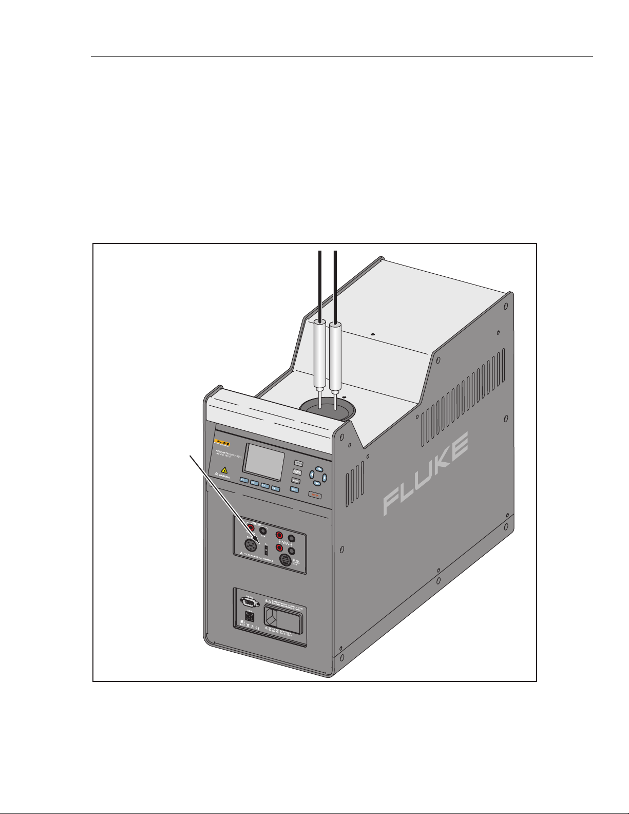
The Fluke Calibration 9190A Ultra-Cool Drywell (the Product or Calibrator) is a benchtop temperature calibrator that can calibrate precision temperature instruments from
−95 °C to 140 °C (see Figure 1-1).
The Calibrator has two models: the 9190A and the 9190A-P. The 9190A-P is a “Process”
version of the 9190A that combines the heat source with a built-in thermometer input
panel. The Input Panel includes an input for an external reference/control thermometer
that makes it possible to perform a transmitter loop calibration, comparison calibration, or
a simple check of a temperature sensor. In addition, the Input Panel can read resistance
and current from a probe. For probes that require power to operate, the 4-20 mA input has
a loop-power function that can source up to 24 volts of power.
-P Option Panel
(Input Panel)
9190A
Figure 1-1. 9190A Ultra-Cool Drywell (-P Option Shown)
gzs053.eps
1-3
Page 14

9190A
Operators Manual
Safety Information
A Warning identifies conditions and procedures that are dangerous to the user. A
Caution identifies conditions and procedures that can cause damage to the Product or the
equipment under test.
See Table 1-1 for a list of symbols used in this manual and on the Calibrator.
Table 1-1. Symbols
Symbol Description Symbol Description
Conforms to European Union
directives
Risk of Danger. Important
information. See manual.
Conforms to relevant North
American Safety Standards.
Conforms to relevant Australian
EMC requirements
Earth ground Hazardous voltage
This product complies with the WEEE Directive (2002/96/EC) marking requirements.
The affixed label indicates that you must not discard this electrical/electronic product
in domestic household waste. Product Category: With reference to the equipment
types in the WEEE Directive Annex I, this product is classed as category 9 "Monitoring
and Control Instrumentation” product. Do not dispose of this product as unsorted
municipal waste. Go to Fluke’s website for recycling information.
Warning
To prevent possible electrical shock, fire, or personal injury:
• Read all safety Information before you use the Product.
• Use the Product only as specified, or the protection
supplied by the Product can be compromised.
• Use this Product indoors only.
• Do not use the Product around explosive gas, vapor, or in
damp or wet environments.
1-4
• Do not use and disable the Product if it is damaged.
• Use only the mains power cord and connector approved for
the voltage and plug configuration in your country and rated
for the Product.
• Replace the mains power cord if the insulation is damaged
or if the insulation shows signs of wear.
• Make sure the ground conductor in the mains power cord is
connected to a protective earth ground. Disruption of the
protective earth could put voltage on the chassis that could
cause death.
• Do not put the Product where access to the mains power
cord is blocked.
• Use caution when you install and remove probes and
inserts from the Product. They can be hot.
Page 15

Product Overview and Specifications
Manual Set 1
• Do not touch voltages > 30 V ac rms, 42 V ac peak, or
60 V dc.
• Do not apply more than the rated voltage, between the
terminals or between each terminal and earth ground.
• Do not touch the well access surface of the instrument.
• Do not turn off the product at block temperatures higher
than 100 °C. Select a SETPOINT less than 100 °C and let the
instrument to cool before turning it off.
• Use the correct terminals, function, and range for
measurements.
• Do not use test leads if they are damaged. Examine the test
leads for damaged insulation, exposed metal, or if the wear
indicator shows. Check test lead continuity.
• Do not touch the probes to a voltage source when the test
leads are connected to the current terminals.
• Keep fingers behind the finger guards on the probes.
• Do not exceed the Measurement Category (CAT) rating of
the lowest rated individual component of a Product, probe,
or accessory.
Manual Set
The Calibrator includes an Operators Manual and a Getting Started Manual. Both
manuals are online at
This 9190A Operators Manual contains feature information, operation instructions, and
basic user maintenance and troubleshooting information.
The 9190A Getting Started Manual is translated and contains basic information to
quickly set up and use the Calibrator.
The 9190A Product CD contains the Operators Manual, the Getting Started Manual, and
the 9190A Remote Operation interface drivers.
www.flukecal.com and on a CD in the Accessory Kit.
Contact Fluke Calibration
To contact Fluke Calibration, call one of the following telephone numbers:
• Technical Support USA: 1-877-355-3225
• Calibration/Repair USA: 1-877-355-3225
• Canada: 1-800-36-FLUKE (1-800-363-5853)
• Europe: +31-40-2675-200
• Japan: +81-3-6714-3114
• Singapore: +65-6799-5566
• China: +86-400-810-3435
• Brazil: +55-11-3759-7600
• Anywhere in the world: +1-425-446-6110
To see product information and download the latest manual supplements, visit Fluke
Calibration’s website at
To register your product, visit http://flukecal.com/register-product.
www.flukecal.com.
1-5
Page 16

9190A
Operators Manual
Calibration and Repair Information
Specifications
Base Unit Specifications
Temperature Range at 23 °C ................................ –95 °C to 140 °C (–139 °F to 284 °F)
Display Accuracy .................................................. ±0.2 °C Full Range
Accuracy with External Reference
Stability .................................................................. ±0.015 °C Full Range
Axial Uniformity at 40 mm (1.6 in) ....................... ±0.05 °C Full Range
Radial Gradient ..................................................... ±0.01 °C Full Range
Loading Effect
(with a 6.35 mm reference
probe and three 6.35 mm probes) ...................... ±0.006 °C Full Range
(versus display with
6.35 mm probes)................................................. ±0.25 °C at –95 °C
±0.10 °C at 140 °C
Operating Conditions ........................................... 0 °C to 35 °C, 0 % to 90 %
Environmental conditions for all
specifications except temperature range ........... 13 °C to 33 °C
Immersion (Well) Depth ........................................ 160 mm (6.3 in)
Well Diameter ........................................................ 30 mm (1.18 in)
Heating Time
Cooling Time
23 °C to –95 °C: 90 min
140 °C to 23 °C: 60 min
Stabilization Time
Resolution ............................................................. 0.01 °
Display ................................................................... LCD, °C or °F user selectable
Size (H x W x D) ..................................................... 480 mm x 205 mm x 380 mm (18.8 in x 8.0 in x 14.9 in)
Weight .................................................................... 16 kg (35 lb)
Power Requirements ............................................ 100 V to 115 V (±10 %) 50/60 Hz, 575 W
200 V to 230 V (±10 %) 50/60 Hz, 575 W
System Fuse Ratings............................................ 115 V: 6.3 A T 250 V
230 V: 3.15 A T 250 V
4–20 mA Fuse (-P model only) ............................. 50 mA F 250 V
Computer Interface ............................................... RS-232, USB Serial, and 9930 Interface-it Temperature Calibration
Safety ..................................................................... IEC 61010-1, Installation Category II, Pollution degree 2
To schedule and send the Calibrator to Fluke for calibration or repair:
1. Contact the Fluke Calibration Service Center in your area to schedule the calibration
or repair (see “Contact Fluke Calibration” on page 1-5).
2. Pack and secure the Calibrator in a shipment box with a minimum of 2 inches of
packing around the Calibrator to prevent damage.
3. Send the Calibrator to the Service Center.
[3]
................. ±0.05 °C Full Range
RH (non-condensing) < 2000 m altitude
[1]
..................................................... –95 °C to 140 °C: 40 min
[1]
..................................................... 23 °C to –90 °C: 80 min
[2]
............................................. 15 min
Software included
1-6
Electromagnetic Environment ............................. IEC 61326-1: Basic
Refrigerants
R32 (Difluoromethane) ....................................... < 20 g, ASHRAE Safety Group A2L
R704 (Helium) ..................................................... < 20 g, ASHRAE Safety Group A1
Page 17

Product Overview and Specifications
Specifications 1
-P Specifications
Built-in Reference Thermometer Readout
Accuracy (4-Wire Reference Probe)
±0.013 °C at –25 °C
±0.015 °C at 0 °C
±0.020 °C at 50 °C
±0.025 °C at 140 °C
Reference Resistance Range............................... 0 Ω to 400 Ω
Reference Resistance Accuracy
42 Ω to 400 Ω: ±60 ppm of reading
Reference Characterizations ............................... ITS-90, CVD, IEC-751, Resistance
Reference Measurement Capability .................... 4 wire
Reference Probe Connection .............................. 6-Pin Din with INFO-CON Technology
Built-in RTD Thermometer Readout Accuracy .. NI-120: ±0.015 °C at 0 °C
PT-100 (385): ±0.02 °C at 0 °C
PT-100 (3926): ±0.02 °C at 0 °C
PT-100 (JIS): ±0.02 °C at 0 °C
RTD Resistance Range......................................... 0 Ω to 400 Ω
Resistance Accuracy
[4]
....................................... 0 Ω to 25 Ω: ±0.002 Ω
25 Ω to 400 Ω: ±80 ppm of reading
RTD Characterizations ......................................... PT-100 (385),(JIS),(3926), NI-120, Resistance
RTD Measurement Capability .............................. 2-wire, 3-wire, and 4-wire RTD with Jumpers only
RTD Connection .................................................... 4-terminal input
Built-in TC Thermometer Readout Accuracy
Type K: ±0.75 °C at 140 °C
Type T: ±0.60 °C at 140 °C
Type E: ±0.60 °C at 140 °C
Type R: ±1.60 °C at 140 °C
Type S: ±1.60 °C at 140 °C
Type M: ±0.65 °C at 140 °C
Type L: ±0.65 °C at 140 °C
Type U: ±0.70 °C at 140 °C
Type N: ±0.75 °C at 140 °C
Type C: ±1.00 °C at 140 °C
TC Millivolt Range ................................................. –10 mV to 75 mV
Voltage Accuracy .................................................. 0.025 % of reading +0.01 mV
Internal Cold Junction
Compensation Accuracy ...................................... ±0.35 °C (ambient of 13 °C to 33 °C)
TC Connection ...................................................... Miniature Connectors (ASTM E1684)
Built-in mA Readout Accuracy ............................ 0.02 % of reading + 0.002 mA
mA Range .............................................................. Cal 4-22 mA, Spec 4-24 mA
mA Connection ..................................................... 2 terminal input
Loop Power Function ........................................... 24 VDC loop power
Built-in Electronics Temperature Coefficient
(0 °C to 13 °C, 33 °C to 50 °C) ............................... ±0.005 % of range per °C
Notes:
[1] – For ambient temperature of 23 °C.
[2] – Time from when the SETPOINT is reached to when the unit is with in Stability specification.
[3] – The temperature range may be limited by the reference probe connected to the readout. The built-in Reference Accuracy does not
include the sensor probe accuracy. It does not include the probe uncertainty or probe characterization errors.
[4] – Measurement accuracy specifications apply within the operating range and assume 4 wires for PRTs. With 3-wire RTDs add 0.05 Ω
to the measurement accuracy plus the maximum possible difference between the resistances of the lead wires.
[5] – The thermocouple input readout is sensitive to EM fields in the frequency range of 500 MHz to 700 MHz.
[3]
................ ±0.010 °C at –95 °C
[4]
..................... 0 Ω to 42 Ω: ±0.0025 Ω
[5]
. Type J: ±0.70 °C at 140 °C
1-7
Page 18

9190A
Operators Manual
1-8
Page 19

Chapter 2
Operation
Title Page
Introduction .......................................................................................................... 2-3
Calibrator Features ............................................................................................... 2-3
Display and Control Panel ............................................................................... 2-4
-P Option Panel (Input Panel) .......................................................................... 2-5
Power and Remote Interface Panel .................................................................. 2-6
Startup and Main Screen ................................................................................. 2-6
Calibrator Setup ................................................................................................... 2-8
Unpack and Inspect ......................................................................................... 2-8
Placement ........................................................................................................ 2-8
Connect to Mains Power ................................................................................. 2-9
Turn On the Product ........................................................................................ 2-9
Change Language ............................................................................................ 2-9
Set Display Contrast ........................................................................................ 2-9
Toggle Key Beep On or Off ............................................................................ 2-10
Security and Password ..................................................................................... 2-10
Menus and Menu Navigation ............................................................................... 2-11
Temperature Setup Menu (TEMP SETUP) ..................................................... 2-11
Temperature Setup ...................................................................................... 2-12
Cutout .......................................................................................................... 2-13
Cooler Status ............................................................................................... 2-14
Program Menu (PROG MENU) ...................................................................... 2-14
Program Setup ............................................................................................. 2-15
Ramp/Soak .................................................................................................. 2-15
Test Result (-P Only) .................................................................................. 2-16
System Menu (SYSTEM MENU) ................................................................... 2-17
Display Setup .............................................................................................. 2-17
Communications Setup ............................................................................... 2-18
Date/Time Setup (-P Only) ......................................................................... 2-18
Calibration Setup Menu ................................................................................... 2-19
Calibration Points Setup .............................................................................. 2-19
Control Setup .............................................................................................. 2-20
Reference Input Calibration (-P Only) ........................................................ 2-21
TC Input Calibration (-P Only) ................................................................... 2-21
mA Input Calibration (-P Only) .................................................................. 2-22
System Information ..................................................................................... 2-22
Input Setup Menu (INPUT SETUP) ................................................................ 2-23
Select Unit Input Menu (-P Only) ............................................................... 2-23
RTD Setup ................................................................................................... 2-24
2-1
Page 20

9190A
Operators Manual
TC Setup ..................................................................................................... 2-25
mA Setup ..................................................................................................... 2-25
Test UUT Calculation ................................................................................. 2-26
REF Input Menu .......................................................................................... 2-26
Reference Probe Setup ................................................................................ 2-27
Test Calculation Menu ................................................................................ 2-28
Probe Preparation ................................................................................................. 2-29
Clamp-On Ferrites ........................................................................................... 2-29
Reference PRT Connection Preparation .......................................................... 2-29
4-Wire Reference Probe Wiring Instructions .............................................. 2-29
2-Wire Reference Probe Wiring Instructions .............................................. 2-29
Reference Probe Input Setup ....................................................................... 2-31
PRT/RTD Connection Preparation .................................................................. 2-32
Operation ............................................................................................................. 2-33
Insert Installation and Removal Procedure ...................................................... 2-33
Probe Insertion and Removal Procedure ......................................................... 2-35
Set Temperature ............................................................................................... 2-36
Set the Temperature SETPOINT Manually ................................................ 2-36
Set the Temperature with a Preset SETPOINT ........................................... 2-36
Change a Preset SETPOINT ....................................................................... 2-37
Cancel or Stop Temperature Change ............................................................... 2-37
Set a Soft Cutout .............................................................................................. 2-37
Reset an Over-Temperature Cutout ................................................................. 2-38
Programs (Automated Tests) ........................................................................... 2-38
Run a Program............................................................................................. 2-38
Stop a Program ............................................................................................ 2-38
2-2
Page 21
Operation
Introduction 2
Introduction
This chapter supplies instructions on how to set up and operate the Calibrator. The
control panels and features of the Calibrator are described first, followed by setup, menus,
and operation.
Calibrator Features
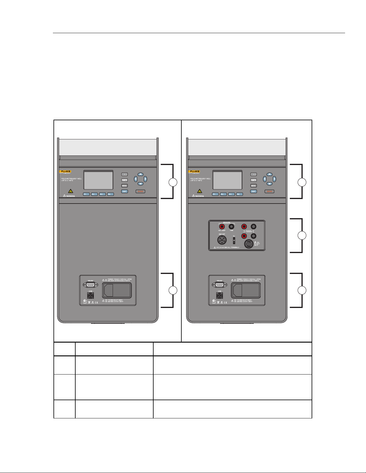
Table 2-1 identifies and describes the panels on the front of the Calibrator.
Table 2-1. The 9190A Front Panel
9190A Model
9190A
1
3
9190A
9190A-P Model
1
2
3
gzs046.eps
Item Name Function
Display and Control Panel
Control panel and display. See “Display and Control Panel” on
page 2-4.
Input panel used to connect to external sensors and probes.
-P Option Panel (Input Panel)
Panel is only available on the “-P” model. See “-P Option Panel”
on page 2-5.
Power and Remote Interface
Panel
Power module and Remote Interface Panel. See “Power and
Remote Interface Panel” on page 2-6.
gzs001.eps
2-3
Page 22
9190A
Operators Manual
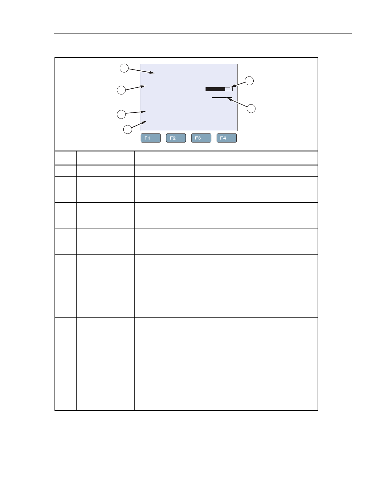
Display and Control Panel
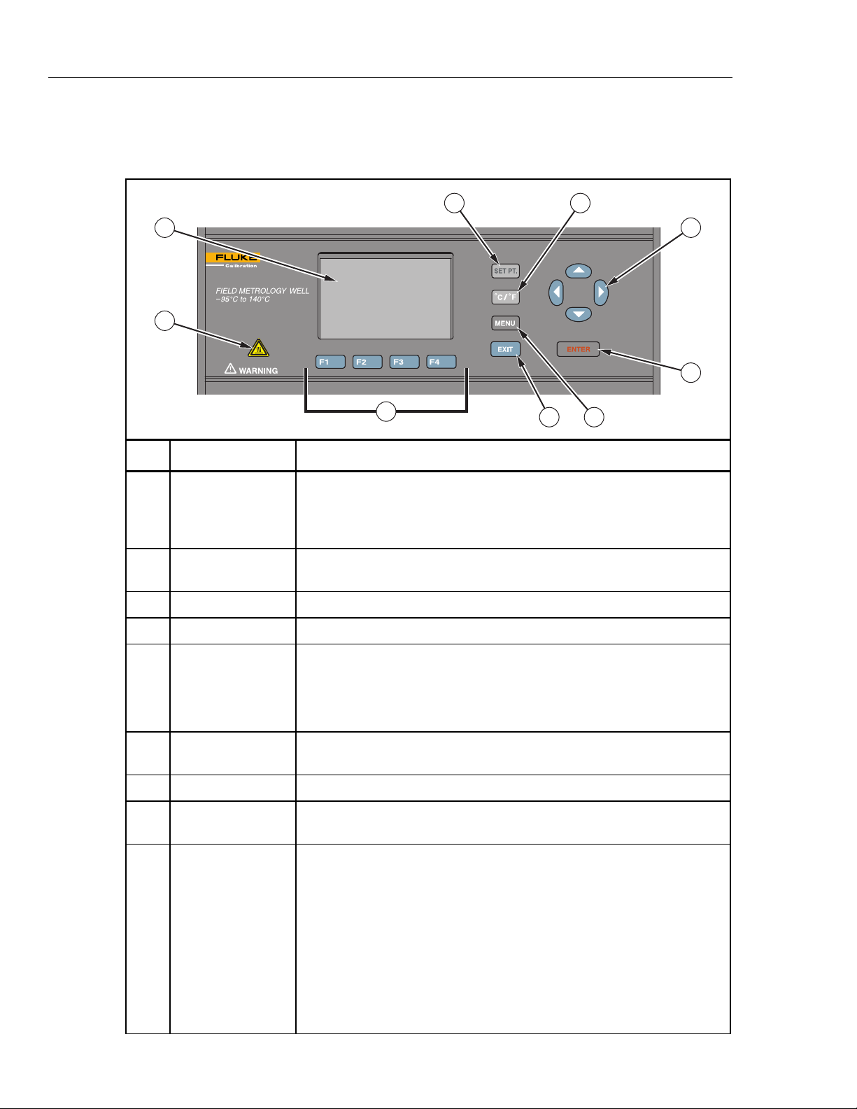
Table 2-2 shows and describes the function of each button on the Control Panel.
Table 2-2. Display and Control Panel
4 5
1
9190A
9
8
Item Name Function
Shows block temperature, measurements, status information, operating
Display
Arrow Keys
▲▼◄►
Enter Key
SET Point Key
parameters, and softkey functions. The contrast of the display is adjustable.
To adjust the contrast, push ▲ to increase contrast or ▼ to decrease
contrast while the Main screen is shown.
Navigates through menu selections, increases or decreases numbers, and
scrolls menus up or down.
Selects menus and sets new values.
Set a SETPOINT temperature to heat or cool to.
2
3
67
gzs002.eps
2-4
°C/°F Key
Menu Key
Exit Key
Softkeys
Block Temperature
Indicator
Switches the displayed temperature units between °C and °F. Key is
enabled only when the Main screen is shown.
Note
This key is disabled in some regions of the world.
Opens the Main menu. See “Menus and Menu Navigation” on page 2-10 for
information on each menu and the settings found in the menus.
Cancels all changes and navigates back to the previous menu.
Navigates the menus on the display. The functions of the softkeys are
shown on the display above the buttons.
Visual safety indicator that illuminates when the block temperature is unsafe
and extinguishes when the block temperature is safe. If the block
temperature is unsafe and the Calibrator is turned off or the mains power
cord is disconnected, the indicator flashes until the block temperature cools
to a safe temperature. Do not transport or remove Inserts until the indicator
is off.
Warning
For safe operation and maintenance of the product, do not
remove Inserts when the Block Temperature indicator is
illuminated.
Page 23
Operation
Calibrator Features 2
-P Option Panel (Input Panel)
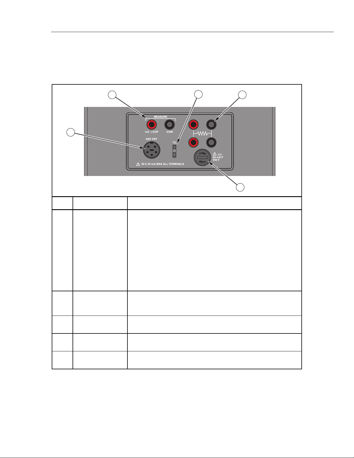
Table 2-3 shows and describes the connectors and ports on the -P Option Panel. The
optional process version -P Option Panel is also referred to as the Input Panel.
Table 2-3. -P Option Panel (Input Panel)
2
1
Item Name Function
Connect a Reference PRT probe to the Calibrator for use with the
reference thermometer function. The Reference Thermometer Input
accepts 4-wire or 2-wire traditional 6-pin DIN Smart Connectors (see
“Reference PRT Connection Preparation” on page 2-29).
Reference
Thermometer Input
(REF PRT)
The Reference Thermometer Input can store calculated probe calibration
coefficients. Coefficient values can be manually keyed into the readout or
a characterization curve can be selected through the user interface.
4
3
5
gzs003.eps
4-20 mA Connectors
4-Wire PRT/RTD
Connector
Thermocouple (TC)
Connector
Fuse
Note
A Platinum Resistance Thermometer (PRT) is the only type of
probe that is supported by the Reference Thermometer Input.
Connect a 4-20 mA transmitter to the Calibrator. The 4-20 mA
Connectors can supply a low voltage (24 V) to power a transmitter. See
“mA Setup” on page 2-25.
Connect a 4-wire, 3-wire, or 2-wire PRT/RTDs to be tested to the input.
See “PRT/RTD Connection Preparation” on page 2-30.
Connect a thermocouple to be tested that is fitted with a subminiature
thermocouple (TC) connector.
Fuse for the 4-20 mA circuit. See Chapter 4 for fuse replacement
instructions.
2-5
Page 24
9190A
Operators Manual
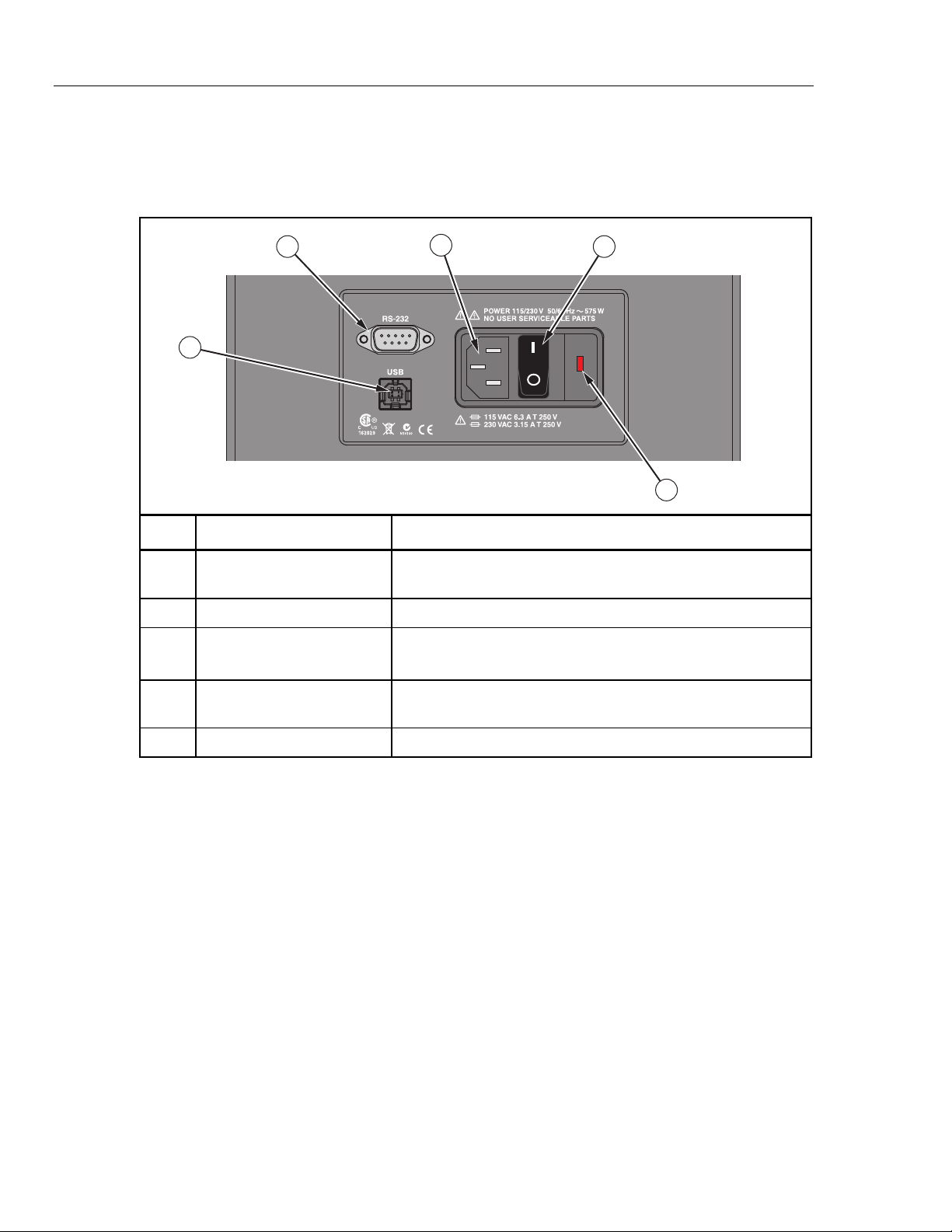
Power and Remote Interface Panel
Table 2-4 shows and describes the connectors and ports on the Power and Remote
Interface Panel.
Table 2-4. Power and Remote Interface Panel
3
4
Item Name Function
Mains Power Cord
Receptacle
Power Switch Turn on (I) and turn off (O) the Calibrator.
9-pin Subminiature
Serial Connector (RS-232)
1
Receptacle for the mains power cord. Use an AC mains supply
appropriate for the voltage range and region of use.
Transmits measurements and remotely controls the operation of
the instrument. See Chapter 3, “Remote Operation”.
2
5
gzs004.eps
USB Serial Connector
Fuse Product fuse. See Chapter 4 for fuse replacement instructions.
Transmits measurements and remotely controls the operation of
the instrument. See Chapter 3, “Remote Operation”.
Startup and Main Screen
When the Calibrator turns on, the system initializes, does a self-check, then shows a
startup screen that shows the model number and firmware version information. If the selfcheck finds an error, the error is shown on the Startup screen. Contact Fluke Calibration
if an error shows on the Startup screen.
After the start-up initialization is complete, the Startup screen disappears and the Main
screen shows on the display. Table 2-4 shows and describes the indicators on the Main
screen.
2-6
Page 25
Operation
Calibrator Features 2
Table 2-5. Main Screen
1
-80.01 °C
2
SETPT: -80.00°C
COOL: 67%
5
3
REF : -79.964 °C
6
TC-T : -79.81 °C
4
Item Name Function
Block Temperature Temperature of the internal temperature block.
SETPOINT
Temperature
Reference
Temperature
UUT Output
Heating/Cooling
Status
[-P Only]
[-P Only]
Target SETPOINT temperature. A set temperature value is referred to as
a “SETPOINT”. The Calibrator uses the SETPOINT value to know what
temperature to heat or cool to.
Shows the most recent reference measurement when a Reference PRT
probe is connected and set up. See “Reference PRT Connection
Preparation” on page 2-29.
Shows the most recent UUT output measurement of a probe that is
connected and setup. The value shown depends on the output type
selected in the Input Setup Menu (see page 2-23).
Shows the mode the calibrator is in. The modes are: OFF, COOL, HEAT,
and CUTOUT. The bar under the mode corresponds to the percent
heating or cooling. The bar is blank at 0 % when HEATING or COOLING
is off or not necessary. The bar is completely dark at 100 % HEATING or
COOLING. CUTOUT is a feature that shuts off power to the heat source if
the well temperature exceeds the set limit value. CUTOUT shows when a
limit has been exceeded. For more information on CUTOUT, see “Cutout”
on page 2-13.
gzs005.eps
Stability Status
Indicator
Visually shows if the block temperature is stable and within the Stability
Limits.
When temperature of the internal temperature block is not within the
Stability Limits, the indicator shows a wavy line (
temperature is within the Stability Limits, the indicator shows as a flat line
(
---) which indicates that a measurement can be made. See “Stability
Limits” on page 2-12.
). When the
Note
To prevent inaccurate measurements, do not make
measurements until the Stability Indicator shows as a flat
line
(---).
2-7
Page 26

9190A
Operators Manual
Calibrator Setup
Unpack and Inspect
9190-INSX Insert (X=A, B, C, D, E, or F) 1
2-meter (6-foot) Mains Power Cord 1
USB Cable 1
Getting Started Manual 1
Product CD that contains manuals and remote interface driver files 1
9930 Interface-it Calibration Software and Users Guide 1
Unpack the instrument carefully and examine it for any damage that could have occurred
during shipment. If there is shipping damage, notify the Fluke Calibration and the carrier
immediately. Table 2-6 lists the equipment and the accessories that comes with the
Calibrator. Verify that all the equipment and accessories in Table 2-6 are in the box.
Table 2-6. Parts and Accessories
Name Quantity
Report of Calibration and Calibration Label 1
Well Insulator Cap 1
Insert Removal Tool 1
Clamp-on Ferrites (-P model only) 4
6-pin DIN Connector (-P model only) 1
Test Lead Kit (-P model only) 1
Placement
Put the Calibrator on a clean, flat surface. Make sure the Calibrator is 150 mm (6 inches)
away from all objects. For best results, choose a location to set up the Product where
room temperature changes are minimum.
Warning
To prevent possible fire or personal injury:
• Do not operate Product in orientations other than upright. A
fire hazard can be made if the Product is put on its side.
• Do not remove Inserts when the Product shows
temperatures more than 50 °C.
• Do not operate near flammable materials.
2-8
• Do not touch the well access surface of the Product.
• Do not turn off the Product when the temperature is above
100 °C. Set a SETPOINT temperature below 100 °C and let
the Product cool.
Page 27

Operation
Calibrator Setup 2
Caution
For safe operation and maintenance of the Product:
• Energize the Product for a 2-hour dry-out period before use, if the
Product was:
o In transport
o In a humid or semi-humid storage environment
o Not energized for more than 10 days
If the product is wet or has been in a wet environment, take
necessary measures to remove moisture prior to applying
power.
• Always operate this Product on a flat, level, stable surface.
• Do not store the Product at temperatures above 50 °C. The
Product has a refrigeration system and contains gasses
under pressure.
• Do not turn the Product upside down. The inserts will fall
out.
• To prevent damage to the cooling system, do not tilt the
Product on its side or upside down while the Product is
operating.
Connect to Mains Power
Use the 2-meter (6-foot) mains power cord to connect the Product to a 120 V ac or 230 V
ac outlet rated for at least 15 amps.
Turn On the Product
1. Push the “I” side of the power switch on the front panel of the Calibrator.
2. Monitor the Startup screen for errors while the product turns on. If an error shows,
contact Fluke Calibration.
Change Language
To change the display language:
1. Push .
2. Push .
3. Push .
4. Push .
5. Push or to highlight a language.
6. Push to set language.
If the incorrect language is set by accident, push softkeys and at
the same time to temporarily switch back to the English language.
Set Display Contrast
With the Main screen shown in the display, push to increase or push to decrease
display contrast.
Note
2-9
Page 28

9190A
Operators Manual
Toggle Key Beep On or Off
Security and Password
Security Level Definition
With the Main screen shown in the display, push and at the same time to
enable or disable key beep.
The Calibrator has two user-level access security levels (Low and High) to protect from
undesired changes to the settings (see Table 2-7). The Calibrator comes from the factory
with the security level set to High and a default password of “1234”.
If the password is not available, the information can still be viewed. To view the
information without the password, push twice or push when prompted for the
password. The information is then shown on the screen, but cannot be changed.
Note
The Calibrator does not have a password reset function. If the password is
lost, contact Fluke Calibration for password reset assistance.
Table 2-7. Security Levels
Low
High
Protects the specific metrological information and calibration information settings.
Protects all operating parameters. It is intended to minimize user choices, for example
to perform repeated identical calibrations under consistent conditions.
To change the password:
1. Push .
2. Push .
3. Push .
4. Enter the current 4-digit password to open the password screen (the default factory
password is
1234).
5. Push and to highlight a digit then push to increase the digit or push to
decrease the digit.
6. Push to save the password.
To change the security level:
1. Push .
2. Push .
3. Push .
2-10
4. Enter the current 4-digit password to open the password screen (the default factory
password is
5. Push and to highlight
1234).
HIGH or LOW.
6. Push to save the selection.
Page 29
Operation
Menus and Menu Navigation 2
Menus and Menu Navigation
The Main menu () contains four submenus that supply access to all features, tools,
and functions. The four submenus are: Temperature Setup, Program Setup, System, and
Input Setup.
Table 2-8 shows and describes the buttons used to navigate the submenus.
Table 2-8. Menu Navigation
Button Navigation Function
Function softkeys to open submenus.
Scroll menus, increases or decreases values, and highlights selections.
Saves changes and navigates to the next menu.
Cancels all changes and navigates back to the Main menu.
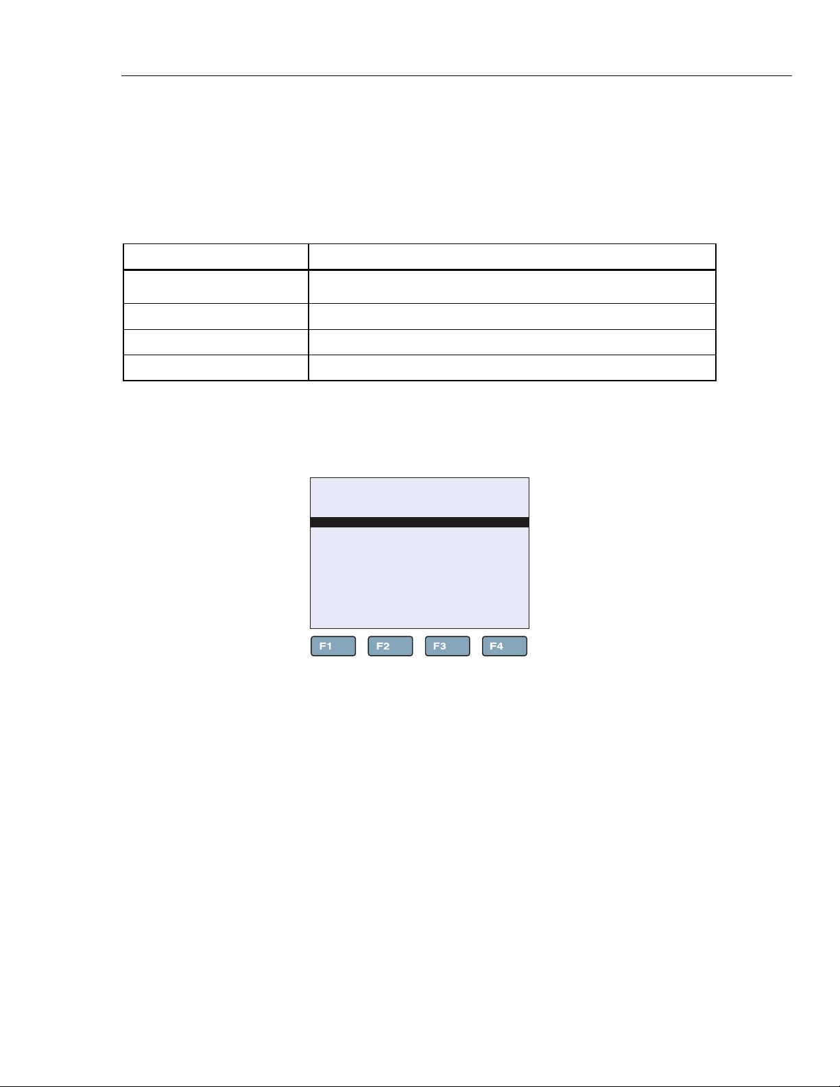
Temperature Setup Menu (TEMP SETUP)
The Temperature Setup menu contains Field Metrology Well functions related to
temperature setup. The TEMP SETUP menu has three submenus: SETUP, CUTOUT,
and STATUS.
66.03°C
TEMERATURE SETUP MENU
SETUP CUTOUT STATUS
Figure 2-1. Temperature Setup Menu
gzs006.eps
2-11
Page 30
9190A
Operators Manual
Temperature Setup
Item Function
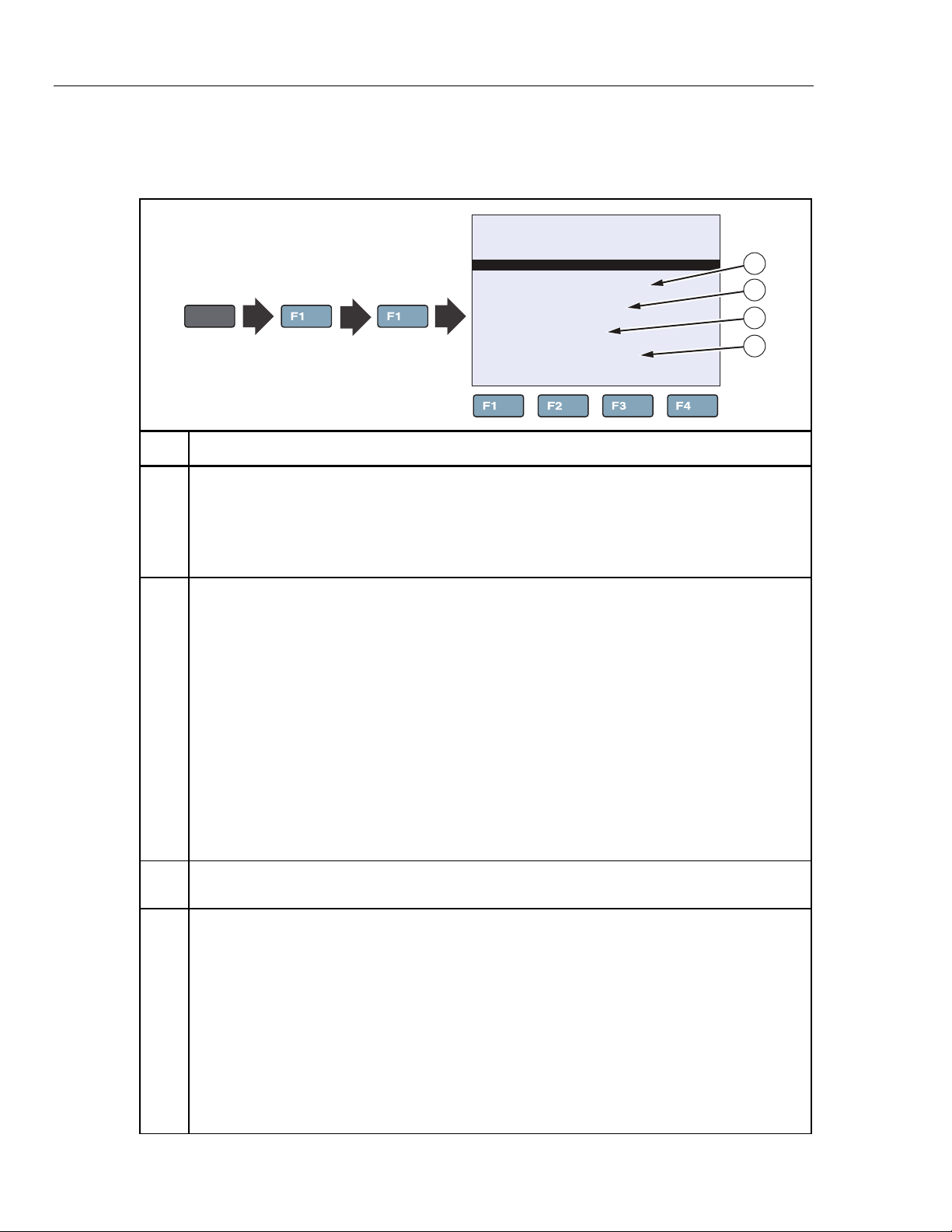
Table 2-9 shows and describes the menu selections on the Temperature Setup menu.
Table 2-9. Temperature Setup Menu
66.03°C
TEMPERATURE SETUP
SCAN RATE: 180.00 °C/m
STABLE LIMIT: 0.04 °C
STABLE ALARM: ON
CONTROL SENSOR: INTERNAL
MENU
TEMP
SETUP SETUP
SCAN RATE sets the rate at which the Calibrator heats or cools in degrees per minute (°C/min or
°F/min). The Scan Rate can be set from 0.1 °C/min to 500 °C/min (0.2 °F/min to 900 °F/min).
Note
The actual Scan Rate is limited to the natural rate the Product heats and cools. This
is less than the maximum Scan Rate setting.
1
2
3
4
gzs007.eps
STABLE LIMIT sets the temperature stability parameter the Calibrator uses to determine when
the temperature is stable enough to make a measurement.
When the temperature is within the range of the Stable Limit, the Calibrator shows a flat bar (---)
on the Main screen (Stability Status Indicator) and audibly sounds the Stable Alarm if it is set to
ON (see item ). The Stable Alarm sounds once per SETPOINT.
Example: A specific calibration process requires the instrument to operate within ±0.1°C. “0.1” is
entered into the Stability Limit parameter. When the block temperature is within ±0.1°C, the
Stability Status indicator on the Main screen changes to a flat line (---) and the Stable Alarm
sounds once.
Note
The 9190A and 9190A-P should not be expected to operate better than the stability
specification found in the Specifications section of this manual. Thus, the minimum setting of
the Stability Limit should not be less than the stability specification. See the “Base Unit
Specifications” in Chapter 1.
STABLE ALARM turns on or turns off the audible Stable Alarm that sounds when the block
temperature is within the Stable Limit. See item .
[-P Only]
CONTROL SENSOR
sets the Calibrator to use the internal sensor or an external sensor to
control the block temperature. The Control Sensor setting has two options: Internal and Reference.
Note
Use of an external sensor such as a PRT can result in improved temperature accuracy
Internal tells the Calibrator to use the internal sensor for temperature control. In return, it relies on
its own calibration for accuracy.
Reference tells the Calibrator to use a PRT that is connected to the Reference Probe input
(REF PRT) for temperature control. In this mode, the temperature of the reference PRT is
measured and shown on the Main screen, and the block temperature is automatically adjusted so
that the temperature of the Reference PRT aligns with the SETPOINT.
.
2-12
Page 31

Operation
Menus and Menu Navigation 2
Cutout
Table 2-10 shows and describes the menu selections on the Cutout menu.
Table 2-10. Cutout Menu
66.03°C
CUTOUT
SOFT CUTOUT: 150 °C
HARD CUTOUT: 160 °C
MENU
TEMP
SETUP CUTOUT
Item Function
SOFT CUTOUT and HARD CUTOUT are limit parameters that shut off power to the heat source
if the well temperature exceeds the set limit value.
The Soft Cutout is a safety barrier to protect probes from temperatures more than their specified
temperature limits.
The Hard Cutout protects the Calibrator from irreparable internal damage. See “Set Soft Cutout”
on page 2-37.
1
gzs008.eps
The Soft Cutout is user configurable and should be set within 5 °C to 10 °C above the
temperature limit of the instrument being calibrated. The Hard Cutout is not user
configurable and is set by the factory to approximately 160 °C.
If the cutout is activated because of an excessive well temperature, the Calibrator enters a
“Cutout mode” where power to the heat source is shut off to immediately cool the Calibrator and
Note
instrument. When in Cutout mode, the instrument displays “
indicator. The instrument stays in Cutout mode until the temperature is below the cutout
SETPOINT and the cutout is reset. See “Reset an Over-Temperature Cutout” on page 2-38.
CUTOUT” above the Stability Status
2-13
Page 32

9190A
Operators Manual
Cooler Status
Table 2-11 shows and describes the menu selections on the Cooler Status menu.
Note
The information on the Cooler Status menu is not editable. Fluke
Calibration Service Center personnel use this information to help
troubleshoot the system if a malfunction occurs.
Table 2-11. Cooler Status Menu
66.03°C
COOLER STATUS
TEMPERATURE: 27.99 °C
SELF TEST: OK
HEAT BALANCE: 0.000
MENU
TEMP
SETUP STATUS
1
2
3
gzs009.eps
Item Function
TEMPERATURE shows the temperature of the condenser.
SELF TEST shows the Stirling Cooler self-test result.
HEAT BALANCE shows the power difference between the top and bottom heaters.
Program Menu (PROG MENU)
The Program menu supplies access to the automated and manual program selections (see
Figure 2-2). A Program is a test that can be configured and run to calibrate an instrument.
66.03°C
PROGRAM MENU
RUN
PROG
RAMP/
SOAK
TEST
RESULT
Figure 2-2. Program Menu
gzs010.eps
2-14
Page 33

Operation
Menus and Menu Navigation 2
Program Setup
Table 2-12 shows and describes the menu selections on the Program Setup menu.
Table 2-12. Program Setup Menu
66.03°C
PROGRAM SETUP
TEST STATUS: OFF
RECORD DATA: NO
TEST ID: 0
MENU
PROG
MENU
RUN
PROG
Item Function
TEST STATUS starts (ON) or stops (OFF) a Program.
RECORD DATA
TEST ID
numeric entry up to 16 characters in length.
[-P Only]
[-P Only]
turns on (YES) or turns off (NO) the data record function of the Program.
is a unique identification of the Program. The identification can be an alpha-
1
2
3
gzs011.eps
Ramp/Soak
Table 2-13 shows and describes the menu selections on the Ramp/Soak Setup menu.
Table 2-13. Ramp/Soak Setup Menu
66.03°C
RAMP/SOAK SETUP
NO. SETPOINTS: 8
SOAK TIME: 15 MIN
NO. CYCLES: 1
DIRECTION:
PASS TOLERENCE: 1.80 °C
MENU
PROG
MENU
RAMP/
SOAK
SET
POINTS
6
Item Function
NO. SETPOINTS is the number of SETPOINTS for a Program. Eight SETPOINTs can be set for
the program. Set the maximum number of SETPOINTS necessary.
SOAK TIME is the duration (in minutes) that each of the programmed SETPOINTS temperature is
maintained. The time starts when the temperature settles to within the specified stability. The
Stability Limit is set in the Temperature Setup menu (see page 2-12).
1
2
3
4
5
gzs013.eps
NO. CYCLES is the number of times that the Program is repeated.
2-15
Page 34

9190A
Operators Manual
Item Function
Test Result (-P Only)
Table 2-13. Ramp/Soak Setup Menu (cont.)
DIRECTION controls whether the SETPOINTS are sequenced in one direction “→” (ascending
from 1 to 8) or in both directions “ ” (ascending from 1 to 8 and then descending from 8 to 1)
before the sequence is repeated. If the both directions option is selected, the Program sequences
from the first SETPOINT to the last and then reverses direction sequencing from the last to the
first.
PASS TOLERANCE
[-P Only]
is the allowable tolerance condition for the test and is used to highlight
test points that have large errors.
SETPOINTS MENU opens a menu to set each of the SETPOINTS for the Program. Only the
number of SETPOINTS defined by NO. SETPOINTS will be displayed.
Table 2-14 shows and describes the menu selections on the Test Result menu. This menu
is available on the -P Model only.
Table 2-14. Test Result Menu
66.03°C
TEST RESULT MENU
PRINT
TEST
ERASE
TEST
2 3
gzs012.eps
MENU
PROG
MENU
TEST
RESULT
VIEW
TEST
1
Item Function
VIEW TEST
PRINT TEST
printed. The data is transmitted from the RS-232 or USB port in ASCII format. Terminal emulator
[-P Only]
opens a menu where test results can be viewed.
[-P Only]
opens a menu to select a programs results and transmit them to a PC to be
or other software can be used to receive the data and save it to a text file on a computer.
ERASE TESTS
[-P Only]
opens a menu to erase test results.
2-16
Page 35

Operation
Menus and Menu Navigation 2
System Menu (SYSTEM MENU)
The System menu lets the user set up the display settings, communications protocol,
date/time settings (-P model only), password settings, calibrations settings, and view
system information (see Figure 2-3).
66.03°C
SYSTEM MENU
SYSTEM
SETUP
PASS
WORD CALIB
SYSTEM
INFO
gzs014.eps
Figure 2-3. System Menu
Display Setup
Table 2-15 shows and describes the menu selections on the Display Setup menu.
Table 2-15. Display Setup Menu
66.03°C
DISPLY
SETUP
DISPLAY SETUP
LANGUAGE: ENGLISH
DECIMAL: PERIOD
KEY AUDIO: ON
MENU
SYSTEM
MENU
SYSTEM
SETUP
Item Function
1
2
3
gzs015.eps
LANGUAGE sets the display language. See “Change Language” on page 2-9.
DECIMAL set the decimal separator to be a period (.) or a comma (,).
KEY AUDIO turns on (ON) or turns off (OFF) the key-beep sound. See “Toggle Key Beep On or
Off” on page 2-10.
With the Main screen shown in the display, push and at the same time to
Note
quickly toggle key beep on or off.
2-17
Page 36

9190A
Operators Manual
Communications Setup
Table 2-16 shows and describes the menu selections on the Communication Setup menu.
Table 2-16. Communication Setup Menu
66.03°C
COMMUNICATION SETUP
BAUD RATE: 9600
LINEFEED: ON
MENU
SYSTEM
MENU
SYSTEM
SETUP
COMM
SETUP
tem Function
BAUD RATE is the serial communication transmission rate or baud rate. BAUD can be set to
1200, 2400, 4800, 9600, 19200, or 38400 baud.
LINEFEED turns on or turns off transmission of a line feed character (LF, ASCII 10) after
transmission of a carriage-return.
Date/Time Setup (-P Only)
Table 2-17 shows and describes the menu selections on the Date and Time Setup menu.
Table 2-17. Date and Time Setup Menu
1
2
gzs016.eps
2-18
66.03°C
DATE/TIME SETUP
TIME: 12:00:00
DATE: 2000-01-01
REPORT DATES: DD/MM/YYYY
MENU
SYSTEM
MENU
SYSTEM
SETUP
DATE
TIME
Item Function
TIME
DATE
REPORT DATE
[-P Only]
sets the internal time of the instrument. The Product uses a 24-hour clock.
[-P Only]
sets the date for the date and time stamp function.
[-P Only]
sets the date format used in the reports.
1
2
3
gzs017.eps
Page 37

Operation
Menus and Menu Navigation 2
Calibration Setup Menu
The Calibration Setup menu supplies access to all calibration parameters for the
Calibrator. Calibration parameters are set at the factory when the instrument is calibrated.
Access to these parameters is protected by a password to prevent unauthorized changes
that could make the Calibrator inoperable. These parameters require periodic adjustments
by trained, knowledgeable personnel to maintain the accuracy of the instrument. For
Calibration instructions, see Chapter 4.
Caution
Do not change the values of the control parameters from the
factory set values. Calibration parameters must be correct for
the instrument to function properly.
Calibration Points Setup
Table 2-18 shows and describes the menu selections on the Calibration Points Setup
menu.
Table 2-18. Calibration Setup Menu
1
MENU
SYSTEM
MENU CALIB
CAL
POINTS
66.03°C
CALIBRATION POINTS
TEMP 1: -0.218
TEMP 2: -0.172
TEMP 3: -0.201
GRAD TEMP: -0.004°C
GRAD 1: -0.029
GRAD 2: -0.013
GRAD 3: 0.062
CAL DATE: 2012-05-01
2
3
4
5
6
7
8
gzs019.eps
Item Function
TEMP 1 sets the offset in °C for the heat source accuracy at the 1st calibration point.
TEMP 2 sets the offset in °C for the heat source accuracy at the 2
nd
calibration point.
TEMP 3 sets the offset in °C for the heat source accuracy at the 3rd calibration point.
GRAD TEMP is a view only parameter that shows the gradient temperature. Fluke Calibration
Service Center personnel use this to help troubleshoot the system if a malfunction occurs.
GRAD 1 sets the offset for the top zone heater control for the axial gradient calibration at the 1
calibration point.
GRAD 2 sets the offset for the top zone heater control for the axial gradient calibration at the 2
calibration point.
GRAD 3 sets the offset for the top zone heater control for the axial gradient calibration at the 3
calibration point.
st
nd
rd
CAL DATE is the calibration date for the Calibrator.
2-19
Page 38

9190A
Operators Manual
Control Setup
MENU
Item Function
Table 2-19 shows and describes the menu selections on the Control Setup menu.
Table 2-19. Control Setup Menu
66.03°C
SYSTEM
MENU CALIB
CONTRL
CONTROL SETUP
TEMP PB: 10.0
TEMP INT: 100.0
TEMP DER: 8.0
GRAD PB: 20.0
GRAD INT: 150.0
REF PB: 10.0
REF INT: 100.0
REF DER: 8.0
1
2
3
4
5
6
7
8
gzs020.eps
TEMP PB sets the main zone proportional band and the gain in °C that the proportional-integral-
derivative (PID) controller uses for main zone control.
TEMP INT sets the main zone integral, which is the integration time in seconds that the PID
controller uses for main zone control.
TEMP DER sets the main zone derivative, which is the derivative time in seconds that the PID
controller uses for main zone control.
GRAD PB sets the gradient proportional band and the gain in °C at the proportional-integral-
derivative (PID) controller uses for gradient zone control.
GRAD INT sets the gradient integral, which is the integration time in seconds that the PID
controller uses for gradient zone control.
REF PB sets the main zone proportional band like item when an external reference probe is
used for control.
REF INT sets the main zone integral like item when an external reference probe is used
control.
REF DER sets the main zone derivative like item when an external reference probe is used
for control.
2-20
Page 39

Operation
Menus and Menu Navigation 2
Reference Input Calibration (-P Only)
Table 2-20 shows and describes the menu selections on the Reference Input Calibration
menu. This menu is available on the -P Model only.
Table 2-20. Reference Input Calibration Menu
MENU
SYSTEM
MENU CALIB
CAL
REF
66.03°C
REFERENCE INPUT CALIBRATION
REF CO: -0.0001
REF C100: 0.0028
INPUT CAL DATE: 2012-05-01
1
2
3
gzs021.eps
Item Function
REF C0
REF C100
INPUT CAL DATE
[-P Only]
adjusts the first calibration point for the reference resistance.
[-P Only]
adjusts the second calibration point for the reference resistance.
[-P Only]
is the calibration date for the readout.
TC Input Calibration (-P Only)
Table 2-21 shows and describes the menu selections on the TC Input Calibration menu.
This menu is available on the -P Model only.
Table 2-21. TC Input Calibration Menu
1
2
3
4
gzs022.eps
MENU
SYSTEM
MENU CALIB
CAL
UUT
CAL TC
66.03°C
TC INPUT CALIBRATION
TC CO: -0.0386
TC C100: -0.0992
TC CRJ: 3.7754
INPUT CAL DATE: 2012-05-01
Item Function
TC C0
TC C100
TC CRJ
INPUT CAL DATE
[-P Only]
adjusts the measurement at 0 mV.
[-P Only]
adjusts the measurement at 100 mV.
[-P Only]
adjusts the reference junction temperature measurement.
[-P Only]
is the calibration date for the TC input.
2-21
Page 40

9190A
Operators Manual
mA Input Calibration (-P Only)
Table 2-22 shows and describes the menu selections on the mA Input Calibration menu.
This menu is available on the -P Model only.
Table 2-22. mA Input Calibration Menu
1
2
3
gzs023.eps
MENU
SYSTEM
MENU CALIB
CAL
UUT
CAL mA
66.03°C
mA INPUT CALIBRATION
mA C4: -0.0075
mA C22: -0.0044
INPUT CAL DATE: 2012-05-01
Item Function
mA C4
mA C22
INPUT CAL DATE
[-P Only]
adjusts the measurement at 4 mA.
[-P Only]
adjusts the measurement at 22 mA.
[-P Only]
is the calibration date for the measurement function of the Calibrator.
System Information
Table 2-22 shows and describes the menu selections on the System Information menu.
Table 2-23. System Information Menu
2-22
1
2
3
4
MENU
SYSTEM
MENU
SYSTEM
INFO
66.03°C
SYSTEM INFORMATION
MODEL: 9190
SERIAL: 022
FW VER: 0.221/0.548
CAL DATE: 2012-05-01
INPUT CAL DATE: 01/05/2012
5
gzs024.eps
Item Function
MODEL shows the model number of the Calibrator.
SERIAL shows the serial number of the Calibrator.
FW VER shows the firmware version of the Calibrator.
CAL DATE shows the calibration date of the heat source.
INPUT CAL DATE
[-P Only]
shows the calibration date for the readout or the -P module.
Page 41

Operation
Menus and Menu Navigation 2
Input Setup Menu (INPUT SETUP)
The Input menu (INPUT MENU) supplies access to the parameters related to the -P
module (process version) or readout function. The parameters found in this menu affect
the performance, accuracy and display type of reference PRTs and UUTs used (see
Figure 2-4). The menus in this section are available on the -P Model only.
66.03°C
INPUT MENU
SELECT
INPUT
SETUP
INPUT
REF
INPUT
gzs026.eps
Figure 2-4. Input Menu
Select Unit Input Menu (-P Only)
Table 2-24 shows and describes the menu selections on the Select Unit Input menu. This
menu is available on the -P Model only.
Table 2-24. Select Unit Input Menu
66.03°C
SELECT UNIT INPUT
SENSOR TYPE: TC
MENU
INPUT
SETUP
SELECT
INPUT
Item Function
1
gzs025.eps
SENSOR TYPE sets the active input for the instrument connected. Selections are: mA, TC, and
RTD.
2-23
Page 42

9190A
Operators Manual
RTD Setup
Table 2-25 shows and describes the menu selections on the RTD Setup menu.
Note
The selections in the SETUP INPUT menu is dependent on the Sensor Type
selected in the SELECT INPUT menu. The SETUP INPUT menu is used to
set up the UUT input or to run the test algorithm.
Table 2-25. RTD Setup Menu
MENU
INPUT
SETUP
SETUP
INPUT
RTD
SETUP
66.03°C
RTD SETUP
WIRES: 3
RTD TYPE: RESISTANCE
1
2
gzs027.eps
Item Function
WIRES configures the RTD input for a 2, 3, or 4-wire input.
RTD TYPE sets up the conversion type for the RTD. RTD characterization types include
PT100(385), PT100(392), PT100(ITS), NI-120, and RESISTANCE.
Note
When RESISTANCE is selected the RTD resistance is shown instead of
temperature.
2-24
Page 43

Operation
Menus and Menu Navigation 2
TC Setup
Table 2-26 shows and describes the menu selections on the TC Setup menu.
Table 2-26. TC Setup Menu
1
gzs028.eps
MENU
INPUT
SETUP
SETUP
INPUT
TC
SETUP
66.03°C
TC SETUP
TC TYPE: TC-E
Item Function
TC TYPE sets the thermocouple conversion type. Standard thermocouple conversions include
types C, E, J, K, L, M, N, R, S, T, and U.
Notes
When mV is selected, the TC Type shows the measurement in uncompensated
millivolts rather than temperature.
The cold junction compensation is measured at the input, automatically computed,
then read by the Calibrator.
mA Setup
Table 2-27 shows and describes the menu selections on the mA Setup menu.
Table 2-27. mA Setup Menu
1
gzs029.eps
MENU
INPUT
SETUP
SETUP
INPUT
mA
SETUP
66.03°C
mA SETUP
LOOP POWER: ENABLE 24V
Item Function
LOOP POWER turns on or turns off the 24 V loop power.
2-25
Page 44

9190A
Operators Manual
Test UUT Calculation
Table 2-28 shows and describes the menu selections on the Test UUT Calculation menu.
Use this function to verify the accuracy of temperature calculations.
Table 2-28. Test UUT Calculation Menu
MENU
INPUT
SETUP
SETUP
INPUT
TEST
CALC
66.03°C
TEST UUT CALCULATION
SENSOR TYPE: TC
INPUT: 0.0000 mV
(TEMPERATURE: 0.000 °F)
1
2
3
gzs030.eps
Item Function
SENSOR TYPE selects the type of sensor for which the temperature calculation is to be tested.
INPUT sets the resistance value or thermocouple millivolt value for the probe connected.
TEMPERATURE shows the calculated temperature for the selected Sensor Type and resistance
or millivolt value.
REF Input Menu
The REF INPUT menu contains the parameters for the reference input to the readout
module of the Calibrator. The Reference Input is only compatible with PRTs with ITS90, Callendar-Van Dusen, or IEC-751 coefficients. Additionally, the Reference Input can
read straight resistance instead of temperature.
2-26
The probe serial number and coefficients can be found on the calibration certificate that
was shipped with the probe. If the probe requires calibration, contact an Authorized
Service Center to inquire about calibration services offered by Fluke Calibration (see
Chapter 1).
Page 45

Operation
Menus and Menu Navigation 2
Reference Probe Setup
Table 2-29 shows and describes the menu selections on the Reference Probe Setup menu.
Table 2-29. Reference Probe Setup Menu
MENU
INPUT
SETUP
REF
INPUT
PROG
PROBE
66.03°C
REFERENCE PROBE SETUP
CAL DATE:
PROBE TYPE:
SERIAL:
RTPW:
A4:
B4:
AL
2000-01-01
ITS-90
100.0000
0.0000000 E-00
A: A:
0.0000000 E-00
B:
0.0000000 E-00
C:
0.0000000 E-00
0.0000000 E-00
1
2
3
4
gzs031.eps
Item Function
SERIAL is the 10-digit, alpha-numeric serial number for the reference probe.
CAL DATE is the Calibration date for the reference probe.
PROBE TYPE is the probe conversion type to be set up. The type can be set to ITS-90, Callendar-
Van Dusen (CVD), IEC-751, or Resistance.
The PRT characterization coefficients that are shown depend on the probe type that was
selected. If ITS-90 is selected, the associated coefficients are a, b, c, a4, and b4. Coefficients a, b,
and c characterize the Reference Probe above 0 °C. Unused coefficients must be set to 0.
Note
If the probe connected is fitted with a smart connector, the PROGRAM prompt
appears when the Reference Probe Setup screen is exited. Select YES to update
the smart connector memory with the present probe setup or NO to leave the
memory unchanged.
2-27
Page 46

9190A
Operators Manual
Test Calculation Menu
Table 2-30 shows and describes the menu selections on the Test Calculation menu. Use
this function to test the accuracy of the temperature calculation for the Reference input.
Table 2-30. Test Calculation Menu
MENU
INPUT
SETUP
REF
INPUT
TEST
CALC
66.03°C
TEST REF CALCULATION
RESISTANCE:
(TEMPERATURE:
0.0000 Ω
0.000)
1
2
gzs032.eps
Item Function
RESISTANCE sets a PRT resistance to be calculated.
TEMPERATURE shows the calculated temperature for the set Resistance value (see item ).
2-28
Page 47

Operation
Probe Preparation 2
Probe Preparation
Clamp-On Ferrites
Ferrites clamped around the PRT/RTD input and the thermocouple (TC) probe reduce the
risk of electro-magnetic interference (EMI) that can cause inaccurate measurements. If
the Calibrator is used in an area that is susceptible to known EMI (such as industrial
equipment or motors), attach a supplied Ferrite to the probe cable as follows:
To attach a ferrite to a probe cable (see Figure 2-5):
1. Make a loop in the cable near the connector.
2. Clamp the ferrite around half of the loop as shown.
3. As necessary, the Ferrite can be snapped open and moved to a new probe.
Connector
Clamp-on Ferrite
Figure 2-5. Clamp-On Ferrite Installation
Reference PRT Connection Preparation
The REF PRT connection on the front panel attaches a reference probe to be used as a
reference thermometer. Prepare the reference probe as follows:
4-Wire Reference Probe Wiring Instructions
Connect a 4-wire reference probe as follows (see Figure 2-6):
1. Connect one pair of wires to pins 1 and 2.
2. Connect the other pair of wires to pins 4 and 5 (pins 1 and 5 source current and pins 2
and 4 sense the potential).
3. If a shield wire is present, connect it to 3, which is also used for the memory circuit.
Pin 6 is only used for the memory circuit.
2-Wire Reference Probe Wiring Instructions
Connect a 2-wire reference probe as follows (see Figure 2-6):
Note
Accuracy can be significantly degraded using a 2-wire connection because
of lead resistance.
1. Connect one wire to both pins 1 and 2.
Probe
gzs038.eps
2. Connect the other wire to pins 4 and 5.
3. If a shield wire is present, connect it to pin 3, which is also used for the memory
circuit. Pin 6 is only used for the memory circuit.
2-29
Page 48

9190A
Operators Manual
Reference Probe
UUT
9190A
2-30
Probe Connector
15
6
2
4
3
Shield
RTD Sensor
Figure 2-6. Reference Probe Wiring
2-Wire Reference Probe4-Wire Reference Probe
Probe Connector
RTD Sensor
15
6
2
4
3
Shield
gzs047.eps
Page 49

Operation
Probe Preparation 2
Reference Probe Input Setup
To set up a reference probe after it is connected:
1. Insert the reference probe into the Calibrator. See “Probe Insertion and Removal
Procedure” on page 2-35.
Note
When the probe with a programmed smart connector is connected to the
REF PRT input, the probe characterization parameters are automatically
transferred to the Calibrator. Additional set up is not necessary to use the
probe.
If the reference probe does not have a smart connector, the PRT
characterization must be set up. The procedure is as follows:
2. Push .
3. Push .
4. Push .
5. Push . If the password is requested, enter the correct password.
7. Enter serial number to identify the Reference Probe. Push and to highlight a digit
then push to increase the digit or push to decrease the digit.
8. Push to save the serial number.
9. Enter the calibration date of the Reference Probe.
10. Select the PRT characterization for Probe Type. Push to select then push to
save.
Note
If the Reference Probe was calibrated and characterized in accordance
with ITS-90, select ITS-90. The PRT characterization coefficients that are
shown depend on the Probe Type that was selected. If ITS-90 is selected,
the associated coefficients are a, b, c, a4, and b4. Coefficients a, b, and c
characterize the Reference Probe above 0 °C. Unused coefficients must be
set to 0.
For example, if the PRT calibration report provides values labeled a8 and
b8, enter the a8 value for a, the b8 value for b, and set c to 0. If the
Reference Probe was calibrated below 0 °C, enter the a4 and b4 coefficient
values on the calibration report in for a4 and b4 in the Calibrator.
After the Reference Probe is setup, it can be used to correct the control temperature of the
Calibrator. To set up the Reference Probe to be the primary sensor:
1. Push .
2. Push .
3. Push again.
4.
Highlight CONTROL SENSOR and push to change it to REFERENCE. See
“Temperature Setup Menu (TEMP SETUP)” on page 2-11.
5. Push to save.
2-31
Page 50

9190A
Operators Manual
PRT/RTD Connection Preparation
The correct wiring for the 4-wire PRT/RTD is shown on the Product. See Figure 2-7 for
an illustration on how to wire a 2-wire, 3-wire, or 4-wire PRT/RTD.
Reference Probe
UUT
9190A
4-Wire PRT
3-Wire PRT 2-Wire PRT
2-32
Figure 2-7. PRT/RTD Probe Setup
gzs044.eps
Page 51

Operation
Operation 2
Operation
Insert Installation and Removal Procedure
Warning
For safe operation and maintenance of the product, do not
remove inserts when the block temperature indicator is
illuminated.
To install the insert:
1. Remove the rubber well insulation cap.
2. Stand the insert upright.
3. Lock the insert tool into the attachment holes.
4. Pick up the insert and slowly and carefully lower the insert into the well.
To remove the insert:
1. Let the Calibrator cool to below 50 °C and make sure the high temperature indicator
is not illuminated.
2. Use the insert tool to lift the insert from the well. Put the insert on a metal or ceramic
fiber surface or container made to set hot materials on.
Note
If the insert has not been cleaned periodically (see “Clean the Insert” in
Chapter 4), hard-water deposits can form on the insert and make it difficult
to remove. If the insert cannot be removed, try to remove the insert as
follows:
a. Put the Calibrator in a cold environment that is less than 21 °C.
b. Use the procedure in “Set the Temperature SETPOINT Manually” on page 2-36
to set the temperature to 100 °C.
c. When the temperature is between 50 °C and 70 °C, use the insert tool to lift the
insert from the well. Put the insert on a metal or ceramic fiber surface or
container made to set hot materials on.
d. If the insert cannot be removed, turn off the Calibrator and contact Fluke
Calibration (see “Contact Fluke Calibration” in Chapter 1).
3. Put the rubber well insulation cap back on the well.
2-33
Page 52

9190A
Operators Manual
Block Temperature
Indicator Light Off
9190A
Figure 2-8. Insert Installation and Removal
gzs045.eps
2-34
Page 53

Operation
Operation 2
Probe Insertion and Removal Procedure
Caution
To prevent possible damage to probes, make sure all probes
put into the furnace are rated for the temperature range used in
the calibration procedure.
Note
Use a metal or ceramic fiber surface or container is used to set hot probes
on.
A solid (unstirred) mass, as in a furnace, can have heat loss through the
probe stem. The loss changes between probes and temperatures.
For the best stable temperature and minimum gradient, put sample probes into the full
depth of the well. Variation on equipment, probe dimension, and configuration can have
an effect on temperature stability and gradients. At higher temperatures, temperature
stability and gradients between test wells are equivalent. But the length of time for the
wells to become stable is much longer.
Temperature changes at lower temperatures are slow. This is because high integration
values are necessary to keep the controller stable (1,200 seconds) at the lower
temperatures.
RTD Probe
9190A
Figure 2-9. Probe Insertion
gzs043.eps
2-35
Page 54

9190A
Operators Manual
Set Temperature
Set the Temperature SETPOINT Manually
A set temperature value is referred to as a “SETPOINT”. The Calibrator uses the
SETPOINT value to know what temperature to heat or cool to. Use the procedures in the
subsequent sections to manually set a SETPOINT, load a SETPOINT preset, or change a
SETPOINT preset.
To adjust the Calibrator temperature SETPOINT manually (see Figure 2-10):
1. Push .
2. Push .
3. Push and to highlight a digit then push to increase the digit or push to
decrease the digit.
4. Push twice to save the SETPOINT temperature and start the Calibrator.
66.03°C
SET TEMPERATURE SETPOINT
SETPOINT:
+080.00 °C
SELECT
PRESET
Figure 2-10. Set Temperature SETPOINT
Set the Temperature with a Preset SETPOINT
The Calibrator stores eight user-configured preset SETPOINT temperatures to help
quickly set a temperature. To change a SETPOINT preset see “Change a SETPOINT
Preset” on page 2-37.
To load and use a preset SETPOINT (see Figure 2-11):
1. Push on the Main screen.
2. Push .
3. Push or to move between presets (1 through 8).
4. Push to select a preset.
66.03°C
SELECT PRESET
PRESET:
(SETPOINT: 80.00 °C)
SAVE/
DISABLE
gzs035.eps
2-36
EDIT
PRESET
Figure 2-11. Preset Selection
gzs034.eps
Page 55

Operation
Operation 2
Change a Preset SETPOINT
To change a preset SETPOINT (see Figure 2-12):
1. Push on the Main screen.
2. Push .
3. Push .
4. Push or to move between presets (1 through 8). Highlight the preset to change
then push .
5. Push and to highlight a digit then push to increase the digit or push to
decrease the digit.
6. Push to save the preset.
66.03°C
EDIT PRESETS
PRESET 1:
PRESET 2:
PRESET 3:
PRESET 4:
+0080.00 °C
+45.00 °C
+26.00 °C
-26.00 °C
Figure 2-12. Edit SETPOINT Preset
Cancel or Stop Temperature Change
To cancel or stop temperature change:
1. Push on the Main screen.
2. Push .
Set a Soft Cutout
Soft Cutout is an upper-heat limit that protects the probes. The Hard Cutout protects the
Calibrator and it cannot be changed (set by factory).
To set a Soft Cutout (see Figure 2-13):
1. Push .
2. Push .
3. Push (if security is set to high, enter password).
4. Push to select the Soft Cutout.
5. Push and to highlight a digit then push to increase the digit or push to
decrease the digit.
6. Push to save the Soft Cutout.
gzs036.eps
2-37
Page 56

9190A
Operators Manual
66.03°C
CUTOUT
SOFT CUTOUT:
(HARD CUTOUT: +160.00 °C)
+090.00 °C
Figure 2-13. Soft Cutout
Reset an Over-Temperature Cutout
If the Soft or Hard Cutout is exceeded, the Calibrator enters Cutout Mode and must be
reset.
To exit Cutout mode and reset the Calibrator:
1. Let the Calibrator cool to below the Soft Cutout limit.
2. After cooled, push followed by to reset the Calibrator.
Programs (Automated Tests)
The Program menu (PROG MENU) supplies access to the automated and manual
Program selections (see “Program Setup” on page 2-15). A Program is an automated test
that can be configured and run on an instrument.
Run a Program
To run a Program:
1. Push .
2. Push .
3. Push .
4. Push to change the
TEST STATUS to RUN.
gzs037.eps
2-38
5. Push to save.
Stop a Program
To stop a Program:
1. Push .
2. Push .
3. Push .
4. Push to change the
5. Push to save.
TEST STATUS to OFF.
Page 57

Chapter 3
Remote Operation
Title Page
Introduction .......................................................................................................... 3-3
Remote Operation Setup ...................................................................................... 3-3
RS-232 Remote Serial Interface ...................................................................... 3-4
Wiring ......................................................................................................... 3-4
Communication Setup ................................................................................. 3-5
USB Remote Interface ..................................................................................... 3-6
Wiring ......................................................................................................... 3-6
Communication Setup ................................................................................. 3-6
Remote Operation Commands ............................................................................. 3-7
Overview of Command Structures .................................................................. 3-7
Commands by Function or Group ................................................................... 3-7
Alphabetical List of Serial Commands ............................................................ 3-13
3-1
Page 58

9190A
Operators Manual
3-2
Page 59

Remote Operation
Introduction 3
Introduction
Remote operation of the Product from a computer is done with commands through the
RS-232 digital interface or a serial USB interface. To control the Calibrator remotely, the
computer sends SCPI (Standard Commands and Programmable Instruments) commands.
These commands let the user change and control all parameters remotely such as
SETPOINT temperatures, cutouts, and programs.
This chapter supplies information on how to set up the remote connection to the PC,
followed by command line information.
Remote Operation Setup
The Calibrator has an RS-232 and USB interface on the Power and Remote Interface
Panel (see Table 3-1).
Note
To prevent noise on the signal wires, use a shielded, low resistance cable
between the Product and PC.
Table 3-1. Power and Remote Interface Panel
3
4
Item Name Function
Mains Power Cord
Receptacle
Power Switch Turn on (I) and turn off (O) the Calibrator.
9-pin Subminiature
Serial Connector (RS-232)
1
Receptacle for the mains power cord. Use an AC mains supply
appropriate for the voltage range and region of use.
Transmits measurements and remotely controls the operation of
the instrument. See Chapter 3, “Remote Operation”.
2
5
gzs004.eps
USB Serial Connector
Fuse Product fuse. See Chapter 4 for fuse replacement instructions.
Transmits measurements and remotely controls the operation of
the instrument. See Chapter 3, “Remote Operation”.
3-3
Page 60

9190A
Operators Manual
RS-232 Remote Serial Interface
Wiring
Use the instructions in the subsequent sections to wire and configure a RS-232 Remote
Serial Interface.
Wire the RS-232 Remote Serial Interface connection as follows:
1. Wire the remote serial interface cable as shown in Figure 3-1.
Note
To prevent noise on the signal wires, use a shielded, low resistance cable
between the Product and PC.
Instrument
Connector
(DB 9-Pin)
1 NC
2 RxD
3 TxD
4 ND
5 GND
6 NC
7 RTS
8 CTS
9 NC
Instrument
Connector
(DB 9-Pin)
1 NC
2 RxD
3 TxD
4 ND
5 GND
6 NC
7 RTS
8 CTS
9 NC
Figure 3-1. RS-232
Computer (DTE)
Connector
(DB 9-Pin)
1 DCD
2 RxD
3 TxD
4 DTR
5 GND
6 DSR
7 RTS
8 CTS
9 NC
Computer (DTE)
Connector
(DB 25-Pin)
1 DCD
2 RxD
3 TxD
4 DTR
5 GND
6 DSR
7 RTS
8 CTS
9 NC
gzs048.eps
3-4
2. Connect the DB-9 connector wired for the instrument to the 9-pin Subminiature
Serial Connector (RS-232) on the Power and Remote Interface Panel (see Table 3-1).
3. Connect the DB-9 or DB-25 connector wired for the computer to the 9-pin or 25-pin
serial port on the computer.
Page 61

Remote Operation
Remote Operation Setup 3
Communication Setup
To use the RS-232 Remote Serial Interface, the Calibrator must be configured to
communicate with the computer. Configuration is done in the Communication Setup
menu on the Calibrator.
Table 3-2. Communication Setup Menu
66.03°C
SYSTEM
MENU
MENU
Item Function
SYSTEM
SETUP
COMM
SETUP
COMMUNICATION SETUP
BAUD RATE: 9600
LINEFEED: ON
1
2
gzs016.eps
BAUD RATE is the serial communication transmission rate or baud rate. BAUD may be set to
1200, 2400, 4800, 9600, 19200, or 38400 baud.
LINEFEED turns on or turns off transmission of a line feed character (LF, ASCII 10) after
transmission of any carriage-return.
Set up communications as follows:
1. Push .
2. Push .
3. Push .
4. Push .
5. Highlight
6. Push or to change the
BAUD RATE and push .
BAUD RATE (see item in Table 3-2).
Note
Set the BAUD RATE to the baud rate that the computer serial port is
configured for.
7. Push to save.
3-5
Page 62

9190A
Operators Manual
USB Remote Interface
Wiring
Communication Setup
Use the instructions in the subsequent sections to wire and configure a USB Remote
Interface.
The Calibrator comes with a standard USB cable. The USB cable has a 1394 connector
(Calibrator connection) on one end and a standard USB connector on the other (computer
connection).
To use the USB interface for remote operation, a driver needs to be installed on the
computer. After the driver is installed and the Calibrator is connected to the computer, the
USB connection appears as a virtual COM port in the PC communication software (for
example, MS Hyper-terminal). The driver is included on the CD that shipped with the
Calibrator. If the CD is lost, or a updated driver is necessary, go to
http://www.ftdichip.com/Drivers/VCP.thm.
To use the USB remote interface, the Calibrator must be configured to communicate with
the computer. Configuration is done in the Communication Setup menu on the Calibrator.
Table 3-3. Communication Setup Menu
66.03°C
SYSTEM
MENU
MENU
Item Function
BAUD RATE is the serial communication transmission rate or baud rate. BAUD may be set to
1200, 2400, 4800, 9600, 19200, or 38400 baud.
LINEFEED turns on or turns off transmission of a line feed character (LF, ASCII 10) after
transmission of any carriage-return.
SYSTEM
SETUP
COMM
SETUP
COMMUNICATION SETUP
BAUD RATE: 9600
LINEFEED: ON
Setup communications as follows:
1. Push .
2. Push .
3. Push .
1
2
gzs016.eps
3-6
4. Push .
5. Highlight
6. Push or to change the
BAUD RATE and push .
BAUD RATE (see item in Table 3-2).
Note
Set the BAUD RATE to the baud rate that the computer serial port is configured for.
7. Push to save.
Page 63

Remote Operation
Remote Operation Commands 3
Remote Operation Commands
Overview of Command Structures
The Calibrator accepts commands for setting parameters, executing functions or
responding with requested data. These commands are in the form of strings of ASCIIencoded characters. The Field Metrology Well command syntax conforms to SCPI-1994.
One notable exception is that compound commands are not allowed as explained below.
Commands consist of a command header and, if necessary, parameter data. All
commands must be terminated with either a carriage return (ASCII 0D hex or 13
decimal) or new line character (ASCII 0A hex or 10 decimal).
Command headers consist of one or more mnemonics separated by colons (:).
Mnemonics may use letter characters, the underscore character (_), and possibly numeric
digits as well. Commands are not case sensitive. Mnemonics often have alternate forms.
Most mnemonics have a long form that is more readable and a short form consisting of
three or four characters that is more efficient.
A mnemonic can end with a numeric suffix that specifies one of a set of independent
function blocks such as input channel data paths. If a numeric suffix is omitted when a
particular block must be specified, an error is generated (“Header suffix out of range”).
Query commands are commands that request data in response. Query commands have a
question mark (?) immediately following the command header. Responses to query
commands are generated immediately and placed in the output buffer. Responses are then
transmitted automatically to the PC. Responses are lost if not read before the next
command is received.
Some commands require parameter data to specify values for one or more parameters.
The command header is separated from the parameter data by a space (ASCII 20 hex or
32 decimal). Multiple parameters are separated by a comma(,).
The Calibrator does not allow compound commands (multiple commands per line
separated with semicolons). All commands are sequential. The execution of each
command is completed before subsequent commands are processed.
Some settings are unconditionally password protected or conditionally password
protected. When protected, a command cannot be used to change the setting without first
providing the password. The password is entered with the SYST:PASS:CEN command.
Commands by Function or Group
In this section, the commands are arranged into the these groups:
•
Calibration Commands – commands for Field Metrology Well calibration
parameters.
•
Main Screen Commands – commands for parameters displayed on the main
screen.
•
Program Commands – commands for program setup and status.
Reference Commands – commands for accessing reference thermometer
•
parameters.
•
UUT Commands – commands for accessing UUT parameters.
•
Setup Commands – commands for setting up communication, display, password,
measure, and operation parameters.
•
System Commands – commands to report and change the status of the instrument.
•
Temperature Commands – commands for control temperature and cutout
functions.
3-7
Page 64

9190A
Operators Manual
Table 3-4. Commands by Function or Group
Group Screen Parameter
Calibration -
Controller
Calibration – Heat
Source
Calibration –
Reference
[-P]
TEMP PB SOUR:LCON:PBAN Unconditional R/W
TEMP INT SOUR:LCON:INT Unconditional R/W
TEMP DER SOUR:LCON:DER Unconditional R/W
CALDATE CAL:DATE:UNIT Unconditional R/W
TEMP 1 SOUR:SENS:CAL:PAR1 Unconditional R/W
TEMP 2 SOUR:SENS:CAL:PAR2 Unconditional R/W
TEMP 3 SOUR:SENS:CAL:PAR3 Unconditional R/W
GRAD 1 SOUR:SENS:CAL:GRAD1 Unconditional R/W
GRAD 2 SOUR:SENS:CAL:GRAD2 Unconditional R/W
GRAD 3 SOUR:SENS:CAL:GRAD3 Unconditional R/W
TEMP 1 SOUR:SENS:CAL:TEMP1 N/A R
TEMP 2 SOUR:SENS:CAL:TEMP2 N/A R
TEMP 3 SOUR:SENS:CAL:TEMP3 N/A R
REF1C0 SENS1:CAL:PAR1 Unconditional R/W
REF1C100 SENS1:CAL:PAR2 Unconditional R/W
Command
Password
Protection
Group
Read/Write
Note:
[-P] – “-P” Model Only
INPUT CAL DATE CAL:DATE:M OD Unconditional R/W
3-8
Page 65

Remote Operation
Remote Operation Commands 3
Table 3-4. Commands by Function or Group (cont.)
Password
Group Screen Parameter
Command
Protection
Group
Read/Write
Calibration – UUT
[-P]
– TC
Calibration – UUT-
mA
Main Screen (none) SOUR:SENS:DATA N/A R
TCC0 SENS2:CAL:PAR1 Unconditional R/W
TCC100 SENS2:CAL:PAR2 Unconditional R/W
TCCRJ SENS2:CAL:PAR3 Unconditional R/W
INPUT CAL DATE CAL:DATE:M OD Unconditional R/W
mAC4 SENS2:CAL:PAR4 Unconditional R/W
mAC20 SENS2:CAL:PAR6 Unconditional R/W
INPUT CAL DATE CAL:DATE:M OD Unconditional R/W
SETPT SOUR:SPO N/A R/W
SETPOINT 1 SOUR:LIST:SPO1 N/A R/W
SETPOINT 2 SOUR:LIST:SPO2 N/A R/W
SETPOINT 3 SOUR:LIST:SPO3 N/A R/W
SETPOINT 4 SOUR:LIST:SPO4 N/A R/W
SETPOINT 5 SOUR:LIST:SPO5 N/A R/W
SETPOINT 6 SOUR:LIST:SPO6 N/A R/W
SETPOINT 7 SOUR:LIST:SPO7 N/A R/W
SETPOINT 8 SOUR:LIST:SPO8 N/A R/W
STAB SOUR:STAB:DAT N/A R
STAB graph SOUR:STAB:TEST N/A R
(none) OUTP2:DATA N/A R
Main Screen
Main Screen
UUT
Program – Run TEST STATUS PROG:STAT N/A R/W
Program - List (none) PROG:CAT N/A R
Program - Select (none) PROG:TYP N/A R/W
Program - Setup TEST ID PROG:IDEN N/A R/W
Erase Tests ERASE TESTS PROG:MEM:CLEA Unconditional W
Note:
[-P] – “-P” Model Only
[-P]
REF CALC1:DATA N/A R
[-P]
REF TEMP READ, MEAS, FETC N/A R
[-P]
TC-n, P100, mA CALC2:DATA N/A R
(none) PROG:MEM:COUN N/A R
3-9
Page 66

9190A
Operators Manual
Ramp & Soak RAMP/SOAK SETUP PROG:SEQ:CAT N/A R
Table 3-4. Commands by Function or Group (cont.)
Group Screen Parameter
SETPOINT n PROG:SEQ:PAR SPOn Conditional R/W
SOAK TIME PROG:SEQ:PAR DWEL Conditional R/W
SETPOINTS PROG:SEQ:PAR POIN Conditional R/W
NO CYCLES PROG:SEQ:PAR CYCL Conditional R/W
PASS TOLERANCE PROG:SEQ:PAR PTOL Conditional R/W
DIRECTION PROG:SEQ:PAR DIR Conditional R/W
Command
Password
Protection
Group
Read/Write
Test – Results
Main Screen
Reference - List
Characterization
Parameters - Active
List (-P model only)
Reference – Setup
[-P]
Reference – Setup
[-P]
Reference – Setup
[-P]
Reference – Setup
[-P]
Note:
[-P] – “-P” Model Only
[-P]
PROBE TYPE CALC1:CONV:CAT N/A R
PRINT TEST PROG:MEM:PRINT N/A W
ERASE TESTS PROG:MEM:CLEA Unconditional W
(none) CALC1:CONV:PAR:CAT N/A R
CAL DATE CALC1:CONV:DATE Conditional R/W
PROGRAM CALC1:CONV:PROG Unconditional W
PROBE TYPE: ITS-90 CALC1:CONV:NAME ITS-90 Conditional R/W
PROBE TYPE: CVD CALC1:CONV:NAME CVD Conditional R/W
PROBE TYPE: IEC CALC1:CONV:NAME IEC-751 Conditional R/W
CONV TYPE:
RESISTANCE
SERIAL CALC1:CONV:SNUM Conditional R/W
CALC1:CONV:NAME RES Conditional R/W
3-10
Page 67

Remote Operation
Remote Operation Commands 3
Table 3-4. Commands by Function or Group (cont.)
Password
Group Screen Parameter
[-P]
ITS90
CVD
RTPW CALC1:CONV:PAR:VAL RTPW Conditional R/W
A CALC1:CONV:PAR:VAL A7 Conditional R/W
B CALC1:CONV:PAR:VAL B7 Conditional R/W
C CALC1:CONV:PAR:VAL C7 Conditional R/W
A4 CALC1:CONV:PAR:VAL A4 Conditional R/W
B4 CALC1:CONV:PAR:VAL B4 Conditional R/W
[-P]
R0 CALC1:CONV:PAR:VAL R0 Conditional R/W
ALPHA CALC1:CONV:PAR:VAL AL Conditional R/W
DELTA CALC1:CONV:PAR:VAL DE Conditional R/W
Command
Protection
Group
Read/Write
BETA CALC1:CONV:PAR:VAL BE Conditional R/W
RESISTANCE SENS1:DATA N/A R
Reference – Test
Algorithm
UUT
List
[-P]
[-P]
RES, mA, mV SENS2:DATA N/A R
[-P]
RTD TYPE CALC2:CONV:CAT RTD N/A R
TEST CALC CALC1:CONV:TEST N/A R
SENSOR SENS2:FUNC N/A R/W
TC TYPE CALC2:CONV:CAT TC N/A R
RTD TYPE: RESISTANCE CALC2:CONV:NAME 0 N/A R/W
RTD TYPE: PT100(385) CALC2:CONV:NAME 1 N/A R/W
RTD TYPE: PT100(3926) CALC2:CONV:NAME 2 N/A R/W
RTD TYPE: PT100(JIS) CALC2:CONV:NAME 3 N/A R/W
RTD TYPE: NI-120 CALC2:CONV:NAME 4 N/A R/W
TC-C CALC2:CONV:NAME C N/A R/W
TC-E CALC2:CONV:NAME E N/A R/W
TC-J CALC2:CONV:NAME J N/A R/W
Note:
[-P] – “-P” Model Only
TC-K CALC2:CONV:NAME K N/A R/W
TC-L CALC2:CONV:NAME L N/A R/W
TC-M CALC2:CONV:NAME M N/A R/W
TC-N CALC2:CONV:NAME N N/A R/W
3-11
Page 68

9190A
Operators Manual
List
UUT–mA
UUT–RTD
UUT – Test Algorithm
Setup - Communication BAUD RATE SYST:COMM:SER:BAUD N/A R/W
Table 3-4. Commands by Function or Group (cont.)
Password
Group Screen Parameter
[-P]
TC-R CALC2:CONV:NAME R N/A R/W
TC-S CALC2:CONV:NAME S N/A R/W
TC-T CALC2:CONV:NAME T N/A R/W
TC-U CALC2:CONV:NAME U N/A R/W
mV CALC2:CONV:NAME MV N/A R/W
[-P]
LOOP POWER INP2:MAMP:LPOW N/A R/W
[-P]
WIRES INP2:RTD:WIR N/A R/W
[-P]
TEST CALC CALC2:CONV:TEST N/A R
Command
Protection
Group
Read/Write
LINEFEED SYST:COMM:SER:LIN N/A R/W
Setup - Display LANGUAGE SYST:LANG N/A R/W
DECIMAL SYST:DEC:FORM N/A R/W
KEY AUDIO SYST:BEEP:KEYB N/A R/W
Setup - Password PASSWORD (Disable) SYST:PASS:CDIS Unconditional W
PASSWORD (Enable) SYST:PASS:CEN Unconditional W
Status (none) SYST:PASS:CEN:STAT N/A R
USER PASSWORD SYST:PASS:NEW Unconditional W
PROTECTION SYST:PASS:PROT N/A R/W
Setup – Date/Time DATE SYST:DATE Unconditional R/W
TIME SYST:TIME Unconditional R/W
System - Setup °C/°F key UNIT:TEMP N/A R/W
Heat Enable (none) OUTP:STAT N/A R/W
(none) SYST:KLOC Conditional R/W
(none) SYST:CONF:MOD N/A R
System - Information (none) SYST:ERR N/A R
3-12
(all) *IDN N/A R
(none) *CLS N/A W
(none) *OPT N/A R
FW VER SYST:COD:VERS N/A R
(none) SYST:BEEP:IMM N/A W
Note:
[-P] – “-P” Model Only
Page 69

Remote Operation
Remote Operation Commands 3
Table 3-4. Commands by Function or Group (cont.)
Password
Group Screen Parameter
Command
Protection
Group
Read/Write
Temperature –
Cutout
Reset (none) SOUR:PROT:CLE N/A W
Tri p Stat e (none) SOUR:PROT:TRIP N/A R
Temperature -
Setup
Temperature –
[-P]
Setup
Note:
[-P] – “-P” Model Only
HARD CUTOUT SOUR:PROT:HCUT N/A R
SOFT CUTOUT SOUR:PROT:SCUT:LEV Conditional R/W
SCAN RATE SOUR:RATE N/A R/W
STABLE LIMIT SOUR:STAB:LIM N/A R/W
STABLE ALARM SOUR:STAB:BEEP N/A R/W
CONTROL SENSOR SOUR:SENS:ROUT {0 | 1 } N/A R/W
Alphabetical List of Serial Commands
Each command description provides the structure (long and short format), a description
of the command purpose, a command example, an example of what the command returns
(as applicable to query commands), and notes specific to the command. The following
apply to each group of commands:
• Numeric data, specified by the mnemonic, <num>, uses ASCII characters to
represent numbers. Numbers may contain a plus or minus (‘+’ or ‘-’) sign, decimal
point (‘.’), and exponent (‘E’ or ‘e’) with its sign. If a fractional component is
received when only an integer is required, the number is rounded to the nearest
integer without any resulting error message. The mnemonics DEF, MIN, and MAX
are often acceptable for the default, minimum, and maximum value respectively. Unit
suffixes, such as V or OHM, can be appended to numeric parameters and are
accepted without error but ignored.
• Unrecognized commands or commands with incorrect syntax or invalid parameters
generate error messages in the error queue.
• Upper case letters designate syntax that is required when issuing the command.
Lower case letters are optional and may be omitted.
• < > indicates a required parameter.
• [ ] indicates optional parameters.
• ( ) indicates a group of parameters that must be used together.
• For query commands, specifying the MIN, MAX, or DEF parameter causes the
instrument to respond with the minimum, maximum, or default setting respectively.
• For set commands, specifying the MIN, MAX, or DEF parameters causes the
instrument to use the minimum, maximum, or default setting respectively.
• ‘|’ indicates alternate parameter values.
• <n> indicates a number is required.
• <num> indicates numeric value is required.
• <prog> indicates a program number (SEQ<n> or SWIT<n>) is required.
3-13
Page 70

9190A
Operators Manual
• <bool> indicates a Boolean value (0 or 1) is required. The mnemonics OFF and ON
are also accepted for 0 and 1, respectively.
• <conv> indicates a conversion mnemonic is required.
• <param> indicates a parameter name is required.
• <seri> indicates a serial number is required.
• <res> indicates a resistance value is required.
• <volt> indicates a voltage value is required.
• <unit> indicates a temperature unit is required.
• <temp> indicates a temperature °C/F is required.
• <pass> indicates a password is required.
• <port> indicates a port number is required.
• <label> indicates an eight character label is required.
• <year> indicates a four digit number is required.
• <month> indicates a one or two digit number is required.
• <day> indicates a one or two digit number is required.
• <hour> indicates a one or two digit number is required.
• <minute> indicates a one or two digit number is required.
• <second> indicates a one or two digit number is required.
• <baud> indicates a valid baud number is required.
*CLS
Clear the status registers.
Example: *CLS
Response: None
*IDN?
Gets manufacturer, model number, serial number and firmware version of the product.
Example: *IDN?
Response:
HART,9190A,A79002,1.00
*OPT?
Read the product configuration, reference hardware enabled (1) or not (0) (see
SYST:CONF:MOD). This command is a read only command and returns the state of the
reference functionality (0, 1).
Example: *OPT?
Response: 1
3-14
Page 71

Remote Operation
Remote Operation Commands 3
CAL:DATE:MOD[?] [<year>,<month>,<day>] (-P model only)
Note
This command is unconditionally protected, that requires a password to set it.
Read or set the calibration date for the -P Module (INPUT CALibration DATE). The entered
values are all numeric and “yyyy” is a four digit year (2000-2135), “mm” is a two digit month
(1-12), and “dd” is a two digit day (1-31).
Read Example: CAL:DATE:MOD?
Response: 2007,05,24
Set Example: CAL:DATE:MOD 2007,12,30
CAL:DATE:UNIT[?] [<year>,<month>,<day>]
Note
This command is unconditionally protected, that requires a password to set it.
Read or set the calibration date for the heat portion of the Calibrator. The entered values are all
numeric and “yyyy” is a four digit year (2000-2135); default 2007, “mm” is a two digit month
(1-12), and “dd” is a two digit day (1-31).
Read Example: CAL:DAT:UNIT?
Response: 2007,05,24
Set Example: CAL:DAT:CAL 2006,12,30
CALC1:CONV:CAT? (-P model only)
Read the list of reference probe characterization methods: “CVD, I90, IEC, RES”. Supplies the
list of PRT/RTD characterization methods available.
Example: CALC1:CONV:CAT?
Response: “CVD”,”I90”,”IEC”,”RES”
CALC1:CONV:DATE[?] [<yyyy,mm,dd>] (-P model only)
Note
This command is unconditionally protected, that requires a password to set it.
Read or set the INFO-CON probe calibration date in yyyy,mm,dd format.
Year Range = {2000 – 2135}; Default: 2007
Month Range = {1 – 12}; Default: 1
Day Range = {1 – 31}; Default: 1
Read Example: CALC1:CONV:DATE?
Response: 2007,10,09
Set Example: CALC1:CONV:DATE 2007,09,06
CALC1:CONV:NAME[?][n] (-P model only)
Note
This command is unconditionally protected, that requires a password to set it.
Read or set the reference probe characterization method. “n” is an alpha numeric value the
represents: CVD, I90, IEC, or RES.
Range={ITS90, CVD, IEC, RES} or 0-3, Default:ITS90.
Read Example: CALC1:CONV:NAME?
Response: CVD
Set Example: CALC1:CONV:NAME I90
3-15
Page 72

9190A
Operators Manual
CALC1:CONV:PAR:CAT? (-P model only)
Read the list of active reference probe characterization parameter names for the current reference
probe type.
Example: CALC1:CONV:PAR:CAT?
Response: “RTPW”,”A”,“B”,“C”,“A4”,“B4”
CALC1:CONV:PAR:VAL[?] par[,<n>] (-P model only)
Read or set a reference probe characterization parameter. “par” is a parameter identified as
follows: ITS90: RTPW, A7, B7, C7, A4, B4; or CVD: AL, DE or BE. “n” may be some real
number or an exponential value such as -1.234567e-5 for ITS-90.
ITS-90 Ranges: {RTPW, A7, B7, A4, B4} or 0 - 5
• RTPW = 1.0 to 200 ohms
• Coefficients = ± 0.010
Defaults:
• RTPW = 100
• All ITS-90 coefficients = 0.00000
• CVD Ranges/Defaults: {R0, AL, DE, BE} or 0 - 3
• R0 = 1.0 to 200.00 ohms
• R0 Default = 100.00
• AL Range = 0.1 to 0.9
• AL Default = 0.00385055
• BE Range = 0.0 to 1.0
• BE Default = 0.10863
• DE Range = 0.0 to 2.0
• DE Default = 1.499786
Note
This command is unconditionally protected, that requires a password to set it.
Read Example: CALC1:CONV:PAR:VAL? RTPW
Response:
Set Example:
100.4545
CALC:CONV:PAR:VAL A7,0.00385075
CALC1:CONV:PROG (-P model only)
Note
This command is unconditionally protected, that requires a password to set it.
Program the INFO-CON probe with the current probe settings.
Example: CALC1:CONV:PROG
3-16
Page 73

Remote Operation
Remote Operation Commands 3
CALC1:CONV:SNUM[?] <ser_num> (-P model only)
Note
This command is unconditionally protected, that requires a password to set it.
Read or enter a reference probe serial number. “ser_num” character range equals {0-9, A-Z, ‘-‘},
up to 10 characters in length with a minimum of 1 character length. Default: “0”
When a blank space is entered, any characters after the blank are dropped. For example, change
S/N 1234-5678 to S/N TEST1. Enter TEST1<Blank Space>678. The serial number will drop the
last three characters and enter the S/N TEST1.
Read Example: CALC1:CONV:SNUM?
Response: 1234
Set Example:
CALC1:CONV:SNUM 1560-D
CALC1:CONV:TEST[?] <n>]
Test the conversion algorithm from resistance (ohms) to temperature (°C or °F). “n” is the value
to be converted (ohms). Entry for “n” is required for converted output.
Range = {0-500};
Default = 100.
Read Example: CALC1:CONV:TEST? 100.000
Response: 0.0100
CAL1:DATA? (-P model only)
Reads the reference sensor Temperature. The returned value will be in degrees °C (°F) if a
temperature value is returned. The value can be a resistance if the conversion selection is
RESISTANCE.
Example: CALC1:DAT?
Response: 325
CALC2:CONV:CAT? <func> (-P model only)
Read the list of UUT probe characterization names. “func” is the UUT device. “func” is not
required and defaults to the selected device based on the setting of <SENS2:FUNC>.
Range = {RTD, TC, MA},
Default = RTD (if no previous selection), else current selection.
Example 1: CALC2:CONV:CAT? TC
Response 1: “C”,”E”,”J”,”K”,”L”,”M”,”N”,”R”,”S”,”T”,”U”,”mV”
If SENS2:FUNC is set to RTD and the command is sent without the function:
Example 2: CAL2:CONV:CAT?
Response 2: “PT_A385”,”PT_A392”,”PT_JIS”,”NI_120”,”RES”
CALC2:CONV:NAME[?] n] (-P model only)
Read or set the UUT device characterization scheme. Must be consistent with the selected
Function and device. For RTD: “n” is the RTD type as follows: PT A385; PT_A392; PT_JIS;
NI_120; or RES. For TC; “n” is the thermocouple type as follows: C; E; J; K; L; M; N; R; S; T;
U; or mV. Default: RTD, PT_A385. Command responds with the selected UUT probe
characterization method; RES, I90, IEC, RES, mV, or mA.
Read Example: CALC2:CONV:NAME?
Response: RTD
Set Example: CALC2:CONV:NAME NI_120
3-17
Page 74

9190A
Operators Manual
CALC2:CONV:TEST? n,[rj] (-P model only)
Test the conversion algorithm from the UUT input. For thermocouple input, “rj” is the reference
junction temperature. If this is not indicated, it is assumed to be 0 °C.
Example: CALC2:CONV:TEST? 100.0
Response: 0.0000
CALC2:DATA? (-P model only)
Read the UUT sensor Temperature. The returned value is in degrees C (°F) if a temperature value
is returned. Value may be resistance, mV, or mA depending on the selected SENS function and
conversion selection.
Example: CALC2:DATA?
Response: 325
INP2:MAMP:LPOW[?] [0|1] (-P model only)
Read or set UUT module mA source where [0] is Passive and [1] enables Loop Power.
Default = 0 (Passive).
Read Example: INP2:MAMP:LPOW?
Response: 1
Set Example: INP2:MAMP:LPOW 1
INP2:RTD:WIR[?] [n] (-P model only)
Read or set the UUT module number of wires in RTD. “n” is the number of wires.
Range = { 2, 3, 4}
Default = 4 wires.
Read Example: INP2:RTD:WIR?
Response: 3
Set Example: INP2:RTD:WIR 4
OUTP:STAT[?] [0|1]
Reads or sets the active heating or cooling output status. A “0” is returned if the output status is
off, and a “1” is returned if the output status is on.
Read Example: OUTP:STAT?
Response: 0
Set Example: OUTP:STAT 1
OUTP:DATA?
Returns the percent heating or cooling power.
Example: OUTP:DATA?
Response: 18.0
PROG:CAT?
A catalog list of all define programs: Ramp & Soak = SEQ.
3-18
Example: PROG:CAT?
Response: “SEQ”,”ASW”,”MSW”
Page 75

Remote Operation
Remote Operation Commands 3
PROG:IDEN[?] [n]
Read or set the program identifier.
Character range = {0 – 9, A – Z, ‘-‘}, up to 12 characters, minimum 1 character: Default: “0”.
Read Example: PROG:IDEN?
Set Example: TEST-1
PROG:MEM:CLE (-P Model only)
Note
This command is unconditionally protected, that requires a password to set it.
Erase all test reports stored in NVMemory.
Example: PROG:MEM:CLE
PROG:MEM:COUN? (-P Model only)
Read the test report count. Provide the count for the number of test reports currently stored in
memory.
Example: PROG:MEM:COUN? 6
PROG:MEM:PRIN [n] [ALL] (-P Model only)
Prints one or all test reports. “n” indicates the test report to be printed and 1 is the earliest test.
Example: PROG:MEM:PRINT 1
PROG:SEQ:CAT?
This command provides a list of the parameters for the Ramp and Soak test.
Example: PROG:SEQ:CAT?
Response: “SPOn”,”DWELL”,”DIR”,”POIN”,”CYCL”,”PTOL”
PROG:SEQ:PAR? par[,<n>]
Read or set a program parameter for Ramp & Soak tests.
Range = {SPOn, DWELL, DIR, POIN, CYCL, PTOL}.
Set Example: PROG:SEQ:PAR cycle,8
Table 3-5. PROG:SEQ:PAR Parameters
Parameter
SPO[n]* 1 8 1
DWEL 1 100 15
Minimum Maximum Default
POIN 1 8 8
CYCL 1 999 1
PTOL 0.01 99.9 1.0 0
DIR 0 (up) 1 (U/D) 0
*Read Only, must be <= # of setpoints (POIN) Read Example: PROG:SEQ:PAR? dwell Response: 25
3-19
Page 76

9190A
Operators Manual
PROG:STAT[?] [0|1]
Read or set the execution state for the selected Program (Off=0, Run=1, Default = 0). If the
selected program is not running then a value of 0 is returned otherwise a 1 is returned.
Read Example: PROG:STAT?
Response: 0
Set Example: PROG:STAT 1
PROG:TYPE[?] [ <prog>]
Read or select a program to run where “prog” is a name, SEQ, ASW, or MSQ.
Default = SEQ.
Read Example: PROG:TYPE?
Response: SEQ
Set Example: PROG:TYPE ASW
READ?, MEAS? or FETC? (-P model only)
Read the Reference sensor temperature, °C or °F. If the external reference probe is enabled, the
reference temperature is returned otherwise, 0.0 is returned.
Example: READ?
Response: 264.262
SENS1:CAL:PAR<n>[?][cal] (-P model only)
Note
This command is unconditionally protected, that requires a password to set it.
Read or set a reference input calibration parameter. “n” is a value of 1 or 2 corresponding to the
calibration parameters REF1C0 and REF1C100 respectively. “cal” is a real number used as the
calibration offset for the respective parameter.
REF1C0 Range = {-1.0 to 1.0} REF1C100
Range = {-2.0 to 2.0} Defaults (all): 0.0000
Read Example: SENS:CAL:PAR1?
Response: 0.2
Set Example: SENS1:CAL:PAR2 0.092
SENS1:DATA? (-P model only)
Read the reference input resistance. This command returns the resistance in ohms of the reference
probe.
Example: SENS1:DATA?
Response: 199.9366
3-20
Page 77

Remote Operation
Remote Operation Commands 3
SENS2:CAL:PAR<n>[?] [cal] (-P model only)
Note
This command is unconditionally protected, that requires a password to set it.
Read or set the UUT input calibration parameter for the selected function. “n” is an integer 1-6.
PAR1=TCC0, PAR2=TCC100, PAR3=TCCRJ, PAR4=mAC4, and PAR6=mAC22 respectively.
“cal” is a real number used as the calibration offset for the respective parameter.
UUT input commands to verify or set TCC0 (PAR1), TCC100 (PAR2), TCCRJ
(PAR3) for the thermocouple (TC) function calibration parameters and mAC4 (PAR4), and
mAC20 (PAR6) for the mili-amp (mA) function calibration parameters.
Range:
TC = ± 10.00 (mV)
mA = ± 4.00 (mA)
Default:
TC = ± 0.00 (mV)
mA = ± 0.00 (mA)
Read Example: SENS2:CAL:PAR1?
Response: 0.2
Set Example: SENS2:CAL:PAR2 0.092
SENS2:DATA? (-P model only)
Read the UUT input. The returned value depends on the set function. PRT/RTD will be in
resistance, TC will be in mV, mA will be in mA. This command returns the UUT input in ohms
for the PRT/RTD function, mV for the thermocouple function, and mA for the current loop
function.
Example: SENS2:DATA?
Response: 0.03
SENS2:FUNC[?] [par] (-P model only)
Read or set the UUT Sense Function (device) selection. “par” is the selected device and is entered
as RTD, TC or MA.
Default = RTD. This command reads or sets the UUT Sense Function as, RTD, TC, or mA.
Read Example: SENS2:FUNC?
Response: RTD
Set Example: SENS2:FUNC TC
SOUR:LCON:DER[?] [n]
Note
This command is unconditionally protected, that requires a password to set it.
Read or set the main control loop derivative time in seconds. The main zone derivative is the
derivative time in seconds that the instrument’s PID controller uses for main zone control.
Range = {Min: 0.0, Max: 99.9}
Read Example: SOUR:LCON:DER?
Response: 1.5
Set Example: SOUR:LCON:DER 5
3-21
Page 78

9190A
Operators Manual
SOUR:LCON:INT[?] [n]
Read or set the main control loop integral time in seconds. The main zone integral is the
integration time in seconds that the instrument’s PID controller uses for main zone control.
Range = {10.0-999.9}
Read Example: SOUR:LCON:INT?
Response: 20.0
Set Example: SOUR:LCON:INT 10
SOUR:LCON:PBAN[?] [n]
Read or set the main control loop proportional band in °C.
Range = {1.0-99.9}
Read Example: SOUR:LCON:PBAN?
Response: 1.5
Set Example: SOUR:LCON:PBAN 7
Note
This command is unconditionally protected, that requires a password to set it.
Note
This command is unconditionally protected, that requires a password to set it.
SOUR:LIST:SPO<i>[?] [n]
Read or set a main temperature preset SETPOINTs.
Read example: SOUR:LIST:SPO6?
Response: 25.00
Set Example: SOUR:LIST:SPO6 100.00
SOUR:PROT:HCUT?
Read the hard cutout temperature set-point in °C or °F. Returns the current value of the hard
cutout SETPOINT
Read Example: SOUR:PROT:HCUT?
Response: 140
SOUR:PROT:CLEA
Reset the cutout to enable the system. If the Calibrator exceeds the temperature set in the soft
cutout menu or if it exceeds the maximum operating temperature, a cutout condition occurs. If
this happens, the Calibrator enters cutout mode and will not actively heat or cool until the user
issues this command to clear the cutout or resets the Calibrator. See Chapter 2.
Example: SOUR:PROT:CLEA
Response: This command has no response.
3-22
Page 79

Remote Operation
Remote Operation Commands 3
SOUR:PROT:SCUT:LEV[?] [n]
Note
This command is conditionally protected, that requires a password to set it.
Read or set the soft cutout SETPOINT. The soft cutout should be set to protect the temperature
limits of the instruments under test. “n” is an integer.
Range = {-125 to 160}
Read Example: SOUR:PROT:SCUT:LEV?
Response: 125
Set Example: SOUR:PROT:SCUT:LEV 105
SOUR:PROT:TRIP?
Read the temperature cutout tripped state. A value of 0 is returned if the cutout set point has not
been reached. Otherwise a value of 1 is returned and the cutout set point has been reached.
Range = {0, 1}; 0 = No Cutout; 1 = Cutout.
Example: SOUR:PROT:TRIP?
Response: 0
SOUR:RATE[?] [n]
Read or set the control temperature rate of change (Scan Rate), °C or °F per minute. The response
to this command starts out high initially and decreases as the SETPOINT is reached.
Range = {Min: 0.10, Max: 500.00} Default: 100.00.
Read Example: SOUR:RATE?
Response: 0.531
Set Example: SOUR:RATE 1.26
SOUR:SENS:CAL:GRAD<x>[?] [n]
Note
This command is unconditionally protected, that requires a password to set it.
Read or set the axial gradient control parameter, where “x” is a numeric value that shows the
parameter. [1] = GRAD1 = GRAD 1, [2] = GRAD2 = GRAD 2, [3] = GRAD3. “n” is a real
number ranging from -1.0 to 1.0 entered as a ratio of the main heater power. The top zone heater
reacts as a ratio of the mains heater power to control the axial gradient.
Read Example: SOUR:SENS:CAL:GRAD2?
Response: 0.05
Set Example: SOUR:SENS:CAL:GRAD2 0.08
SOUR:SENS:CAL:PAR<x>[?] [n]
Note
This command is unconditionally protected, that requires a password to set it.
Read or set a control temperature calibration parameter. “x” is a numeric value that shows the
parameter. [1] = PAR1=Temp 1,PAR2=Temp 2, PAR3=Temp 3. “n” is the entered value of the
parameter. Range = ±50.00; Defaults: 0.000. The Chapter 4 for more information.
Read Example: SOUR:SENS:CAL:PAR1?
Response: 0.0
Set Example: SOUR:SENS:CAL:PAR2 0.02
3-23
Page 80

9190A
Operators Manual
SOUR:SENS:CAL:TEMP<x>?
Read the required calibration temperature (°C) that corresponds to a calibration parameter. “x” is
a numeric value indicating the parameter [1] = TEMP1, [2] = TEMP2, AND [3] = TEMP3.
Range = {1-3}; Default = 1.
Example: SOUR:SENS:CAL:TEMP1?
Response: 40
SOUR:SENS:DATA? [TEMP]
Read the control temperature, °C or °F. The current control temperature is returned if the above
or if TEMP is appended to the end of the example.
Example: SOUR:SENS:DATA? or SOUR:SENS:DATA? TEMP
Response: 30.285°C (current control temp)
SOUR:SENS:DATA? [RES]
Read the control sensor resistance. When RES is appended to the end of the example above, the
internal sensor resistance is returned.
Example: SOUR:SENS:DATA? RES
Response: 111.28
SOUR:SENS:ROUT {0 | 1}
Enable/disable the external control sensor.
SOUR:SPO[?] [n]
This command reads or sets the value of the control SETPOINT in the temperature unit set.
Range = {Min -110.00, Max 140.00} Default = 25.00
Read Example: SOUR:SPO?
Response: 50.000
Set Example: SOUR:SPO 100.00
SOUR:STAB:BEEP[?] [n]
Enable or disable the audible stability alert.
[0] is disable, [1] is enable beep.
Default:1 (Enable Beep).
Read Example: SOUR:STAB:BEEP?
Response: 1
Set Example: SOUR:STAB:BEEP 0
SOUR:STAB:DAT?
Read the control temperature stability, °C or °F. The controller stability is returned.
Example: SOUR:STAB:DAT?
Response: 0.306
3-24
Page 81

Remote Operation
Remote Operation Commands 3
SOUR:STAB:LIM[?] [n]
Read or set the control temperature stability limit, °C or °F. “n” is a positive real value.
Range = {0.01 to 9.99 (°C)}; Default: 0.05 (°C).
Read Example: SOUR:STAB:LIM?
Response: 0.05
Set Example: SOUR:STAB:LIM 0.03
SOUR:STAB:TEST?
Read the temperature stability test results. A value of 0 is returned if the controller is not stable at
the current SETPOINT. Otherwise a value of 1 is returned if the controller is stable at the current
SETPOINT.
Stable = 1; Unstable = 0.
Example: SOUR:STAB:TEST?
Response: 0
SYST:BEEP:IMM
Beep the system beeper. The system beeper should make an audible sound in response to this
command.
Example: SYST:BEEP:IMM
SYST:BEEP:KEYB[?] [n]
Read or set the keyboard beep function.
0=Off, 1=On. Default: 1.
Read Example: SYST:BEEP:KEYB?
Response: 1
Set Example: SYST:BEEP:KEYB 1
SYST:CODE:LANG?
Read the language set option: 1: European; 2: Asian.
European: ENGLish (default), FRENch, GERMan, PORTuguese, SPANish, RUSSian
Asian: ENGLish (default), CHINese, JAPanese, KORean
Example: SYST:CODE:LANG?
Response: 2
SYST:CODE:VERS?
Read the main code version. Supplies the user with the version of the main processor code.
Example: SYST:CODE:VERS?
Response: 1.10
SYST:COMM:SER:BAUD[?] [<baud>]
Read or set serial interface baud rate where “baud” is a standard baud rate value.
Range baud = {1200, 2400, 4800, 9600, 19200, and 38400}; Default: 9600.
Read Example: SYST:COMM:SER:BAUD? Response: 2400
Set Example: SYST:COMM:SER:BAUD 9600
3-25
Page 82

9190A
Operators Manual
SYST:COMM:SER:LIN[?] [n]
Set serial interface linefeed enable. “n” is a value 1 or 0.
[0] = LF OFF, [1] = LF ON; Default: 1 (OFF).
Read Example: SYST:COMM:SER:LIN?
Response: 0
Set Example: SYST:COMM:SER:LIN 1
SYST:CONF:MOD?
Read the presence of the –P module.
[0] if no –P sensor module, [1] if –P sensor card is installed
Example: SYST:CONF:MOD?
Response: 1
SYST:DATE[?] [<year>,<month>,<day>] (-P model only)
Read or set the System Date Setting with numbers separated by commas (yyyy,mm,dd).
Note
This command is conditionally protected, that requires a password to set it.
Read Example: SYST:DATE?
Response: 2007,05,24
Set Example: SYST:DATE 2007,05,24
SYST:DEC:FORM[?] [n]
Read or set the decimal format. “n” is period [0], comma [1]. Default: 0 (Period)
Read Example: SYST:DEC:FORM?
Response: 0
Set Example: SYST:DEC:FORM 1
SYST:ERR?
Read the most resent error from the error queue. This command response reports the errors in the
error queue.
Example: SYST:ERR?
Response: command protected
SYST:KLOC[?] [n]
Note
This command is unconditionally protected, that requires a password to set it.
Locks or unlocks the system keypad that restricts control to only through the serial interface
(RS-232 port) or the keypad.
[0] = unlock, and [1] = lock. Default: 0 (Unlock).
3-26
Read Example: SYST:KLOCK?
Response: 1
Set Example: SYST:KLOC 1
Page 83

Remote Operation
Remote Operation Commands 3
SYST:LANG <lang>
Set the display language. The available languages are dependent upon which version of the
product is supplied. The version is dependent upon the final destination and configuration.
European: ENGLish (default), FRENch, GERMan, PORTuguese, SPANish, RUSSian
Asian: ENGLish (default), CHINese, JAPanese, KORean
Example: SYST:LANG SPAN
SYST:LANG:CAT?
Read the available display languages. The available languages are dependent upon which version
of the product is supplied. The version is dependent upon the final destination and configuration.
European: ENGLish (default), FRENch, GERMan, PORTuguese, RUSSian, SPANish
Asian: ENGLish (default), CHINese, JAPanese, KORean
Example European: SYST:LANG:CAT?
Response: “ENGL”,”FREN”,”SPAN”,”PORT”,”GERM”,“RUSS”
SYST:PASS:CDIS
Disable access to password protected setting commands. This command disables the system
password protection.
Example: SYST:PASS:CDIS
Response: This command has no response.
SYST:PASS:CEN [n]
This command enables the system password. This password needs to be enabled in order to use
the conditionally protected commands. When the power of the instrument is cycled, system
password protection is disabled. “n” is a four digit password.
Range = {0000 – 9999}; Default: 1234.
Example: SYST:PASS:CEN 1234
Response: This command has no response.
SYST:PASS:CEN:STAT?
Read the access state of password protected setting commands. This command reports the current
status of the system password.
Example: SYST:PASS:CEN:STAT?
Response: 0
SYST:PASS:NEW <n>|DEF
Note
This command is unconditionally protected, that requires a password to set it.
Set the password, where “n” is the new four digit password.
Range = {0000 – 9999}; Default: 1234.
Example: SYST:PASS:NEW 1234
Response: This command has no response.
3-27
Page 84

9190A
Operators Manual
SYST:PASS:PROT[?] [0|1]
Read or set password protection level.
[0] = low, [1] = high
Read Example: SYST:PASS:PROT?
Response: 0
Set Example: SYST:PASS:PROT 1
SYST:TIME[?] [<hh,mm,ss] (-P model only)
Read or set the System Time <hh,mm,ss> (24 hr time only).
Range: hh = {0 – 23}, mm = {0 – 59}, ss = {0 – 59}
Example: SYST:TIME?
Response: 23,51,05
Set Example: SYST:TIME 14,15,05
UNIT:TEMP[?] [n]
Note
This command is conditionally protected, that requires a password to set it.
Read or set the display temperature units, where “n” is a character “C” or “F”.
Default: C.
Read Example: UNIT:TEMP?
Response: C
Set Example: UNIT:TEMP F
3-28
Page 85

Chapter 4
Calibration
Title Page
Introduction .......................................................................................................... 4-3
Temperature Source Calibration .......................................................................... 4-3
Fundamentals ................................................................................................... 4-4
Terminology .................................................................................................... 4-5
Calibration Equipment ..................................................................................... 4-6
Temperature Source Specifications ................................................................. 4-6
Environmental Conditions ............................................................................... 4-6
Temperature Source Calibration Procedure..................................................... 4-6
UUT and Equipment Setup ......................................................................... 4-6
As Found Data Collection ........................................................................... 4-8
Uniformity Alignment 1st Iteration ............................................................. 4-9
Uniformity Alignment 2nd Iteration ........................................................... 4-10
Uniformity Alignment 3rd Iteration ............................................................ 4-10
Accuracy Alignment ................................................................................... 4-12
As Left Accuracy ........................................................................................ 4-13
As Left Uniformity ...................................................................................... 4-13
As Left Stability .......................................................................................... 4-14
Guard Bands ................................................................................................ 4-14
9190A Input Panel Calibration ............................................................................ 4-15
Fundamentals ................................................................................................... 4-15
Terminology .................................................................................................... 4-15
Calibration Equipment ..................................................................................... 4-16
Environmental Conditions ............................................................................... 4-17
Input Panel Calibration Procedure ................................................................... 4-17
Input Panel Calibration/Tests ...................................................................... 4-17
Readout Specifications ................................................................................ 4-17
Reference Accuracy Test ............................................................................ 4-17
UUT PRT 4-Wire Test ................................................................................ 4-18
UUT PRT 3-Wire Test ................................................................................ 4-19
Reference Accuracy Alignment .................................................................. 4-20
UUT Thermocouple Calibration ................................................................. 4-21
Thermocouple Accuracy Test ..................................................................... 4-21
Thermocouple Reference Junction Accuracy Test ...................................... 4-22
Thermocouple Reference Junction and Accuracy Alignment ..................... 4-22
Thermocouple Accuracy Alignment ........................................................... 4-23
4-20 mA Input Calibration .......................................................................... 4-23
4-20 mA Accuracy Test .............................................................................. 4-23
24 V Source Test ......................................................................................... 4-24
4-20 mA Accuracy Alignment .................................................................... 4-24
4-1
Page 86

9190A
Operators Manual
4-2
Page 87

Calibration
Introduction 4
Introduction
This chapter contains calibration procedures for the Calibrator.
Note
The Calibrator is referred to as the UUT (unit under test) in the calibration
procedures in this Chapter.
Temperature Source Calibration
Figure 4-1 shows a flow chart of the calibration procedure.
Note
For assistance with the calibration process, contact an Authorized Service
Center. See “How to Contact Fluke Calibration” in Chapter 1.
This procedure is to be considered a general guideline. Each laboratory
should write their own procedure based on their equipment and their
quality program. Each procedure should be accompanied by an uncertainty
analysis also based on the laboratory’s equipment and environment.
4-3
Page 88

9190A
Operators Manual
Calibration
Procedure Start
Set up calibration
equipment
(-P Model)?
Yes
Input Panel
Calibration
Thermocouple
Accuracy Test
Thermocouple
Reference Junction
Accuracy Test
Thermocouple
Reference Junction
Alignment
Thermocouple
Accuracy
Alignment
Thermocouple
Accuracy Test
Reference
Accuracy Test
Calibration Process Flow Chart
4-20 mA
Accuracy Test
No
Temperature
Source
Temperature
Source
Calibration
Done
Accuracy Test
Yes
24V Source
Test
4-20 mA
Accuracy
Alignment
4-20 mA
Readout
passed?
No
UUT PRT 4-Wire
Accuracy Test
UUT PRT 3-Wire
Accuracy Test
Reference
Accuracy
Alignment
Fundamentals
1. Only personnel that are qualified should calibrate the product.
2. Input panel calibration or temperature source calibration may be optional and
depends on UUT configuration and customer requirement.
Reference
Accuracy Test
UUT PRT 4-Wire
Accuracy Test
Figure 4-1. Calibration Procedure
UUT PRT 3-Wire
Accuracy Test
Repeat
gzs051.eps
4-4
Page 89

Calibration
Temperature Source Calibration 4
Terminology
Table 4-1 lists the terms that are used throughout this procedure.
Table 4-1. Calibration Terminology
Term Definition
UUT Unit under test (for this procedure, this is the 9190A)
Test Sleeve Insert A cylindrical aluminum insert with drilled probe holes that fits into the UUT.
Readout Electronic device that can measure the probe resistance and convert it to
temperature.
PRT Platinum Resistance Thermometer (also referred to as a temperature probe).
Primary PRT or
Primary Reference
Secondary PRT or
Secondary Ref
As Found Data Data taken on the UUT before it is adjusted.
As Left Data Data taken on the UUT after it is adjusted.
SETPOINT Target temperature value the UUT controls to.
Axial Uniformity
Error or Uniformity
Error
The temperature probe that is placed in the insert front hole at 0 mm. (Probe is
bottomed out in the front-insert hole.) See Figure 4-2.
The temperature probe that is placed in the insert rear hole at 30 mm up from the
bottom of the Insert. The Reference Probe bottoms out at 30 mm in the rear insert
hole. Figure 4-2.
The difference in temperature at one height in the UUT temperature block to a
different height in the temperature block along the vertical axis.
4-5
Page 90

9190A
Operators Manual
Calibration Equipment
Readout 20 ppm Fluke Calibration 1560 with a
PRT 0.008 °C at 0 °C 5628 Secondary Standard PRT
Readout 20 ppm Fluke Calibration 1560 with a
The equipment in Table 4-2 is required to complete the calibration procedure.
Table 4-2. Calibration Equipment
Primary Reference
Classifications Minimum Use Specifications Suggested Equipment
2560 SPRT Module
with R
Secondary Reference
Classifications Minimum Use Specifications Suggested Equipment
2560 SPRT Module
Calibration
TPW
PRT 0.008 °C at 0 °C 5628 Secondary Standard PRT
with R
Aluminum Insert Two, 0.25 inch diameter x 6.25
inch deep holes
Calibration
TPW
Temperature Source Specifications
See specifications in Chapter 1.
Environmental Conditions
Laboratory environmental conditions required to complete this procedure:
• Temperature range: 23 °C ± 4 °C. Temperature needs to be stable when calibration is
in progress.
• Low wind and draft area.
• Ambient relative humidity: below 60 %
Temperature Source Calibration Procedure
UUT and Equipment Setup
Put the primary PRT and the secondary PRT in the Insert as shown in Figure 4-2. Elevate
the secondary PRT 30 mm off the bottom of the Insert.
4-6
Page 91

Calibration
Temperature Source Calibration 4
To Readout (see “Suggested Equipment” in Table 4-2)
Secondary PRT (30 mm)
Primary PRT (0 mm)
Test Sleeve Insert
9190A
Figure 4-2. Test Sleeve Orientation
gzs052.eps
Connect both PRTs to the readout. It is best to make simultaneous measurements of both
the primary and secondary PRT when PRT data is measured from the readout. If the
readout only has one input channel, take the primary PRT readings back to back with the
secondary PRT without delay.
A remote connection to the product is required to complete this procedure. Use the
instructions in Chapter 3 “Remote Operation” to set up the remote connection to the
UUT.
4-7
Page 92

9190A
Operators Manual
As Found Data Collection
If As Found data is not needed, do not perform this procedure and start the Uniformity
Alignment 1
st
Iteration procedure on page 4-9.
Collect the data as follows:
1. Set the UUT SETPOINT temperature to 140 °C. Monitor the UUT Stability Status
indicator to make sure the temperature is stable.
2. Let the UUT to soak at the 140 °C SETPOINT for 45 minutes after the Stability
Status indicator shows that the temperature is stable (flat line). Take 40
measurements from the primary PRT and the secondary PRT simultaneously.
Calculate the average temperature and 2σ (2 x standard deviation) of the
measurements taken. Also calculate the uniformity error as follows:
Uniformity Error = PRT secondary – PRT primary
Enter the results in Table 4-3 and Table 4-4. Compare the results to the specifications
in Chapter 1.
3. Continue to record the temperature of the primary reference probe for 30 minutes and
compute the standard deviation and multiply by two. Enter the result in Table 4-5.
Compare the result to the specification.
Repeat the As Found Data Collection procedure for each of the other SETPOINT
temperatures listed in Table 4-3, Table 4-4, and Table 4-5.
Table 4-3. As Found Accuracy Results
Average
UUT
SETPOINT
°C
140 °C 40 0.200 °C 0.02 °C
100 °C 40 0.200 °C 0.02 °C
25 °C 40 0.200 °C 0.02 °C
0 °C 40 0.200 °C 0.02 °C
−45 °C 40 0.200 °C 0.02 °C
−95 °C 40 0.200 °C 0.02 °C
Number of
Samples
PRT
Primary
Reading
°C
Error: PRT
Primary –
SETPOINT
°C
Specification
(±°C)
2σ PRT
Primary
2σ Limit
(over the
samples)
40
4-8
Page 93

Calibration
Temperature Source Calibration 4
Table 4-4. As Found Uniformity Results
UUT
SETPOINT °C
140 °C 40 0.05 °C
100 °C 40 0.05 °C
25 °C 40 0.05 °C
0 °C 40 0.05 °C
−45 °C 40 0.05 °C
−95 °C 40 0.05 °C
SETPOINTS °C Stability 2σ Spec (±°C)
140 °C 0.015 °C 45 30
0 °C 0.015 °C 45 30
−95 °C 0.015 °C 45 30
Number of
Samples
Average PRT
Table 4-5. As Found Stability Specifications
Secondary
Reading °C
Average PRT
Primary °C
Uniformity
Error °C =
Soak Time
PRTsecPRTprim
(minutes)
Specification
(minutes)
°C
Duration
Uniformity Alignment 1st Iteration
Perform the 1
st
Uniformity Alignment as follows:
1. Set the UUT SETPOINT temperature to -90 °C and engage the temperature control.
2. Monitor the Stability Status indicator to ensure the heat source is stable. Let the UUT
soak at the -90 °C SETPOINT for 45 minutes after the Stability Status indicator
shows that the temperature is stable (flat line). Measure the ACTUAL gradient,
which is the temperature of the secondary PRT (30 mm probe) minus the temperature
of the primary PRT (0 mm probe). Take the average of 40 samples for each of the
probes. Calculate as follows:
ACTUAL grad = T
30
- T0
3. Query the UUT gradient sensor reading with this serial command:
SOUR:SENS:GRAD:DATA?
4. Repeat this 40 times to get an average of the gradient sensor reading. This value is
called “UUT grad”. Calculate the Error with this formula:
ERROR
5. If the magnitude of ERROR
temperature and repeat the Uniformity Alignment 1
= UUT grad – ACTUAL grad
1
is less than 0.012, skip to the next Gradient calibration
1
st
Iteration procedure.
6. Query the UUT GRAD 1 calibration parameter as follows:
SOUR:SENS:CAL:GRAD1?
7. Grad 1 is associated with UUT block temperature -90 °C. Calculate the new Grad 1
calibration parameter as follows:
New
= GRAD 1 – ERROR1
GRAD 1
4-9
Page 94

9190A
Operators Manual
8. Enter the New
> SYSTEM MENU > CALIB > CAL POINTS
calibration parameter into the UUT from the front panel: MENU
GRAD 1
parameter to the UUT with these serial commands:
SYST:PASS:CEN <password>
SOUR:SENS:CAL:GRAD1 <New_GRAD 1>
9. Let the UUT soak at the -90 °C SETPOINT for 45 minutes after the change to the
New
GRAD 1
parameter.
Uniformity Alignment 2nd Iteration
Perform the 2
nd
uniformity alignment as follows:
1. With the UUT still at -90 °C from the previous Uniformity Alignment 1
procedure, measure the ACTUAL gradient, which is the temperature of the secondary
PRT (30 mm probe) minus the temperature of the primary PRT (0 mm probe). Take
the average of 40 samples for each of the probes. Calculate as follows:
ACTUAL grad = T
30
- T0
2. Query the UUT gradient sensor reading with this serial command:
SOUR:SENS:GRAD:DATA?
3. Repeat this 40 times to get an average of the gradient sensor reading. This value is
called “UUT grad”. Calculate the Error with this formula:
ERROR
= UUT grad – ACTUAL grad
1
or send the New
GRAD 1
calibration
st
Iteration
4. If the magnitude of ERROR
temperature and repeat the Uniformity Alignment 1
5. Query the UUT GRAD 1 calibration parameter with this command:
SOUR:SENS:CAL:GRAD1?
6. Grad 1 is associated with UUT block temperature -90 °C. Calculate the new Grad 1
calibration parameter as follows:
New
7. Enter the New
> SYSTEM MENU > CALIB > CAL POINTS
= GRAD 1 – ERROR1
GRAD 1
GRAD 1
calibration parameter into the UUT from the front panel: MENU
parameter to the UUT with these serial commands:
SYST:PASS:CEN <password>
SOUR:SENS:CAL:GRAD1 <New_GRAD 1>
8. Let the UUT soak at the -90 °C SETPOINT for 45 minutes after the change to the
New
GRAD 1
parameter.
Uniformity Alignment 3rd Iteration
Perform the 3
rd
uniformity alignment as follows:
1. With the UUT still at -90 °C from the previous Uniformity Alignment 2
procedure, measure the ACTUAL gradient, which is the temperature of the secondary
PRT (30 mm probe) minus the temperature of the primary PRT (0 mm probe. Take
the average of 40 samples for each of the probes. Calculate as follows:
is less than 0.012, skip to the next Gradient calibration
1
st
Iteration procedure.
or send the New
GRAD 1
calibration
nd
Iteration
4-10
ACTUAL grad = T
30
- T0
2. Query the UUT gradient sensor reading with this serial command:
Page 95

Calibration
Temperature Source Calibration 4
SOUR:SENS:GRAD:DATA?
3. Repeat this 40 times to get an average of the gradient sensor reading. This value is
called “UUT grad”. Calculate the Error with this formula:
ERROR
4. If the magnitude of ERROR
temperature and repeat the Uniformity Alignment 1
= UUT grad – ACTUAL grad
1
is less than 0.012, skip to the next Gradient calibration
1
st
Iteration procedure.
5. Query the UUT GRAD 1 calibration parameter with this serial command:
SOUR:SENS:CAL:GRAD1?
6. Calculate the new Grad 1 calibration parameter as follows:
New
7. Enter the New
> SYSTEM MENU > CALIB > CAL POINTS
= GRAD 1 – 0.7 x ERROR1
GRAD 1
calibration parameter into the UUT from the front panel: MENU
GRAD 1
or send the New
GRAD 1
calibration
parameter to the UUT with these serial commands:
SYST:PASS:CEN <password>
SOUR:SENS:CAL:GRAD1 <New_GRAD 1>
8. Let the UUT soak at the -90 °C SETPOINT for 45 minutes after the change to the
GRAD1 parameter.
9. With the UUT still at -90 °C from the previous Uniformity Alignment 3
rd
Iteration
procedure, measure the ACTUAL gradient, which is the temperature of the secondary
PRT (30 mm probe) minus the temperature of the primary PRT (0 mm probe). Take
the average of 40 samples for each of the probes. Calculate as follows:
ACTUAL grad = T
30
- T0
10. Query the gradient sensor reading from the UUT , with this serial command:
SOUR:SENS:GRAD:DATA?
11. Repeat this 40 times to get an average of the gradient sensor reading. This value is
called “UUT grad”. Calculate the Error with this formula:
ERROR
12. If the magnitude of ERROR
= UUT grad – ACTUAL grad
1
is less than 0.012, skip to the next Grad cal temperature.
1
If the magnitude of the error is still greater than 0.012, contact an authorized Fluke
Calibration Service Center (see Chapter 1).
st
13. Repeat the Uniformity Alignment 1
Iteration procedure for the SETPOINT
temperatures listed below:
• 0 °C
• 140 °C
4-11
Page 96

9190A
P
N
Operators Manual
Accuracy Alignment
An Accuracy Alignment is a measurement of the UUT block temperature and then
comparing the error between what the primary PRT measures and what the UUT shows.
This is done for the three different temperatures specified.
Perform the Accuracy Alignment as follows:
1. Let the UUT soak at the 140 °C SETPOINT for 45 minutes. Send this serial
command to read the UUT display temperature:
SOUR:SENS:DATA?
2. Take the average of 40 samples of the UUT display temperature (UUT
Take the average of 40 samples from the primary PRT (ACTUAL
TEMP
DISP_TEMP
). Calculate as
).
follows:
NEW
OLD
= OLD
OFFSET3
= the current accuracy offset parameter stored in the UUT for the
OFFSET3
OFFSET3
– (ACTUAL
TEMP
- UUT
DISP_TEMP
)
140 °C point.
3. Enter the NEW
MENU > SYSTEM MENU > CALIB > CAL POINTS > TEMP_3 or send these
value calibration parameter into the UUT from the front panel:
OFFSET3
serial commands:
SYST:PASS:CEN <password>
SOUR:SENS:CAL:PAR3 XXX.XXX
4. Repeat the procedure for these UUT block temperatures:
• 0 °C
• -90 °C
• 0 °C
5. Measure the 0 °C point twice, once descending in temperature, and once ascending in
temperature.
6. Take the average of the two 0 °C data sets for the (Block
) value when calculating
TEMP
the accuracy offset parameter. Use this equation:
4-12
NEW
OFFSET2
= OLD
OFFSET2
–
ACTUAL
TEMP
– (UUT
DISP TEMP U
2
+ UUT
DISP TEMP DOW
)
7. Use Table 4-6 to determine the correct calibration parameter to adjust for each of the
SETPOINT temperatures.
Table 4-6. Accuracy Calibration Parameter Serial Commands
Temperature Calibration Parameter Serial Command
−90 °C TEMP1 SOUR:SENS:CAL:PAR1[?]
0 °C TEMP2 SOUR:SENS:CAL:PAR2[?]
140 °C TEMP3 SOUR:SENS:CAL:PAR3[?]
Page 97

Calibration
Temperature Source Calibration 4
As Left Accuracy
Take primary PRT data at each of the UUT SETPOINT temperatures listed in Table 4-7.
Let the UUT stabilize and then soak for 45 minutes for each of the temperatures.
Table 4-7. As Left Accuracy Specifications
Average
UUT
SETPOINT
°C
140 °C 40 0.200 °C 0.02 °C
100 °C 40 0.200 °C 0.02 °C
25 °C 40 0.200 °C 0.02 °C
0 °C 40 0.200 °C 0.02 °C
−45 °C 40 0.200 °C 0.02 °C
−95 °C 40 0.200 °C 0.02 °C
Number of
Samples
PRT
Primary
Reading
°C
Error: PRT
Primary –
SETPOINT
°C
Specification
(±°C)
2σ PRT
Primary
As Left Uniformity
rd
The final uniformity data found in step 11 of the Uniformity Alignment 3
Iteration can
be used for the As Left uniformity data. Use the data from the final iteration for each of
the three different temperatures.
Table 4-8. As Left Uniformity Results
Uniformity
UUT
SETPOINT °C
Number of
Samples
Average PRT
Secondary °C
Average PRT
Primary °C
Error °C =
PRTsecPRTprim
Specification
2σ Limit
(over the
40
samples)
°C
140 °C 40 0.05 °C
100 °C 40 0.05 °C
25 °C 40 0.05 °C
0 °C 40 0.05 °C
−45 °C 40 0.05 °C
−95 °C 40 0.05 °C
4-13
Page 98

9190A
Operators Manual
As Left Stability
Guard Bands
Take stability data at the temperatures listed in Table 4-9. Compare the results to the
specification. The data can be taken after the accuracy data is taken in As Left Accuracy
for each of the temperatures listed in Table 4-9.
Table 4-9. As Left Stability Specifications
SETPOINT °C 2σ Spec (±°C) Soak time min Duration min
140 °C 0.015 °C 45 30
0 °C 0.015 °C 45 30
−95 °C 0.015 °C 45 30
Guard bands are used to make sure the UUT is calibrated to a level better than the actual
specification. This compensates for any drift that can occur over the calibration interval.
If drift does occur, the unit would still be in specification. The guard bands can be applied
differently to the As Found specification and the As Left specification. Typically the As
Left guard band is tighter than the As Found guard band. Guard band limits are
determined by the user and are decided by criteria such as:
• Calibration interval
• Environmental conditions
• Unit performance
4-14
Page 99

Calibration
9190A Input Panel Calibration 4
9190A Input Panel Calibration
Note
For assistance with the calibration process, contact an Authorized Service
Center. See “How to Contact Fluke Calibration” in Chapter 1.
This procedure is to be considered a general guideline. Each laboratory
should write their own procedure based on their equipment and their
quality program. Each procedure should be accompanied by an uncertainty
analysis also based on the laboratory’s equipment and environment.
Figure 4-1 shows a flow chart of the calibration procedure.
Fundamentals
1. Only personnel that are qualified should calibrate the product.
2. Input panel calibration or temperature source calibration may be optional and
depends on UUT configuration and customer requirement.
Terminology
If the optional process version (-P model) was purchased, the 9190A has an additional
input panel that requires routine calibration. The optional process version (-P model) is
also referred to as the Input panel (see –P Option Panel in Chapter 2).
Table 4-10 lists the terms that are used throughout this procedure.
Table 4-10. Calibration Terminology
Term Definition
UUT Unit under test (for this procedure, this is the 9190A)
Test Sleeve Insert A cylindrical aluminum insert with drilled probe holes that fits into the UUT.
Readout Electronic device that can measure the probe resistance and convert it to
temperature.
PRT Platinum Resistance Thermometer (also referred to as a temperature probe).
Primary PRT or
Primary Reference
Secondary PRT or
Secondary Ref
As Found Data Data taken on the UUT before it is calibrated.
As Left Data Data taken on the UUT after it is calibrated.
SETPOINT Target temperature value the UUT controls to.
Axial Uniformity
Error or Uniformity
Error
The temperature probe that is placed in the insert front hole at 0 mm. (Probe is
bottomed out in the front-insert hole.) See Figure 4-2.
The temperature probe that is placed in the insert front hole at 30 mm. The
Reference Probe bottoms out at 30 mm in the rear insert hole. Figure 4-2.
The difference in temperature at one height in the UUT temperature block to a
different height in the temperature block along the z axis. The Axial Uniformity is
referred to as the Vertical Gradient.
4-15
Page 100

9190A
Operators Manual
Calibration Equipment
Four-Wire Resistors See Table 4-12
Voltage/Current Source Voltage: ± 6 ppm + 0.6 μV
Ice Point 25 °C, Stability: ±0.02 °C
Readout Accuracy: 0.0025 °C
Probe 0.02 °C at 25 °C
Thermocouples 0.025 °C at 25 °C
The equipment in Table 4-11 is required to complete the calibration procedure.
Table 4-11. External Reference Calibration Equipment Specifications
Classification Minimum Use Specifications
Amperage: ± 40 ppm + 80 nA
Type E characterized wire at 25 °C
Table 4-12. Standard Resistor Specifications
U
(k=1) US2 (k=1) UT (k=1) UT (k=2)
S1
Reference
Resistor
Resistance
(Ω)
0 -- 0.000040 -- -- 0.00004 0.00008
25 1.80 0.000045 0.3 0.0000075 0.000045 0.00009
100 2.00 0.00020 0.3 0.00003 0.000205 0.00041
200 2.65 0.00053 0.3 0.00006 0.00055 0.0011
400 2.65 0.00106 0.3 0.00012 0.0011 0.0022
Uncertainty
(ppm)
Reference
Resistor
Uncertainty
(Ω)
TCR
Uncertainty
(ppm)
TCR
Uncertainty
(Ω) Total Uncertainty (Ω)
4-16
 Loading...