

Page 1

9133
Infrared Thermometer Calibrator
User’s Guide
Rev. 180601
Page 2

Copyright © 2002 All Rights Reserved
Hart Scientific, Inc.
799 E. Utah Valley Drive
American Fork, Utah 84003-9775
Telephone: (801) 763-1600 • Fax: (801) 763-1010
Internet: http://www.hartscientific.com
E-mail: support@hartscientific.com
Rev. 180601
Page 3

Table of Contents
1 Before You Start . . . . . . . . . . . . . . . . . . . . . . . 1
1.1 Symbols Used. . . . . . . . . . . . . . . . . . . . . . . . . . 1
1.2 Safety Information. . . . . . . . . . . . . . . . . . . . . . . . 2
1.3 Customer Service Information . . . . . . . . . . . . . . . . . 3
2 Introduction . . . . . . . . . . . . . . . . . . . . . . . . . 5
3 Specifications and Environment Conditions . . . . . . . . 7
3.1 Specifications . . . . . . . . . . . . . . . . . . . . . . . . . . 7
3.2 Environmental Conditions . . . . . . . . . . . . . . . . . . . . 8
3.3 Warranty. . . . . . . . . . . . . . . . . . . . . . . . . . . . . 8
4 Safety Guidelines . . . . . . . . . . . . . . . . . . . . . . 11
5 Quick Start . . . . . . . . . . . . . . . . . . . . . . . . . 13
5.1 Unpacking . . . . . . . . . . . . . . . . . . . . . . . . . . . 13
5.2 Set Up . . . . . . . . . . . . . . . . . . . . . . . . . . . . . 13
5.3 Power . . . . . . . . . . . . . . . . . . . . . . . . . . . . . 13
5.4 Setting the Temperature . . . . . . . . . . . . . . . . . . . . 14
6 Parts and Controls . . . . . . . . . . . . . . . . . . . . . 15
6.1 Back Panel. . . . . . . . . . . . . . . . . . . . . . . . . . . 15
6.2 Front Panel . . . . . . . . . . . . . . . . . . . . . . . . . . . 16
7 General Operation . . . . . . . . . . . . . . . . . . . . . 19
7.1 Changing Display Units . . . . . . . . . . . . . . . . . . . . 19
7.2 Switching to 230 V Operation . . . . . . . . . . . . . . . . . 19
7.3 Ice Buildup/Purge . . . . . . . . . . . . . . . . . . . . . . . 19
8 Controller Operation . . . . . . . . . . . . . . . . . . . . 21
8.1 Target Temperature . . . . . . . . . . . . . . . . . . . . . . 21
8.2 Temperature Set-point . . . . . . . . . . . . . . . . . . . . . 21
8.2.1 Programmable Set-points . . . . . . . . . . . . . . . . . . . . . . . . 21
8.2.2 Set-point Value. . . . . . . . . . . . . . . . . . . . . . . . . . . . . . 23
8.3 Temperature Scale Units. . . . . . . . . . . . . . . . . . . . 24
8.4 Scan . . . . . . . . . . . . . . . . . . . . . . . . . . . . . . 24
i
Page 4

8.4.1 Scan Control . . . . . . . . . . . . . . . . . . . . . . . . . . . . . . . 24
8.4.2 Scan Rate . . . . . . . . . . . . . . . . . . . . . . . . . . . . . . . . 25
8.5 Set-point Resistance. . . . . . . . . . . . . . . . . . . . . . 25
8.6 Temperature Scale Units. . . . . . . . . . . . . . . . . . . . 25
8.7 Secondary Menu. . . . . . . . . . . . . . . . . . . . . . . . 25
8.8 Heater Power . . . . . . . . . . . . . . . . . . . . . . . . . 25
8.9 Proportional Band . . . . . . . . . . . . . . . . . . . . . . . 26
8.10 Controller Configuration . . . . . . . . . . . . . . . . . . . . 27
8.11 Operating Parameters . . . . . . . . . . . . . . . . . . . . . 28
8.12 Serial Interface Parameters . . . . . . . . . . . . . . . . . . 28
8.12.1 BAUD Rate. . . . . . . . . . . . . . . . . . . . . . . . . . . . . . . . 28
8.12.2 Sample Period . . . . . . . . . . . . . . . . . . . . . . . . . . . . . . 29
8.12.3 Duplex Mode . . . . . . . . . . . . . . . . . . . . . . . . . . . . . . . 29
8.12.4 Linefeed . . . . . . . . . . . . . . . . . . . . . . . . . . . . . . . . . 30
8.13 Calibration Parameters. . . . . . . . . . . . . . . . . . . . . 30
8.13.1 R0 . . . . . . . . . . . . . . . . . . . . . . . . . . . . . . . . . . . . 31
8.13.2 ALPHA . . . . . . . . . . . . . . . . . . . . . . . . . . . . . . . . . . 31
8.13.3 DELTA . . . . . . . . . . . . . . . . . . . . . . . . . . . . . . . . . . 31
8.13.4 BETA . . . . . . . . . . . . . . . . . . . . . . . . . . . . . . . . . . . 31
9 Digital Communication Interface . . . . . . . . . . . . . 33
9.1 Serial Communications . . . . . . . . . . . . . . . . . . . . 33
9.1.1 Wiring . . . . . . . . . . . . . . . . . . . . . . . . . . . . . . . . . . 33
9.1.2 Setup. . . . . . . . . . . . . . . . . . . . . . . . . . . . . . . . . . . 33
9.1.2.1 BAUD Rate . . . . . . . . . . . . . . . . . . . . . . . . . . . 34
9.1.2.2 Sample Period . . . . . . . . . . . . . . . . . . . . . . . . . 34
9.1.2.3 Duplex Mode . . . . . . . . . . . . . . . . . . . . . . . . . . 34
9.1.2.4 Linefeed . . . . . . . . . . . . . . . . . . . . . . . . . . . . . 35
9.1.3 Serial Operation . . . . . . . . . . . . . . . . . . . . . . . . . . . . . 35
9.2 Interface Commands. . . . . . . . . . . . . . . . . . . . . . 35
10 Calibration Procedure . . . . . . . . . . . . . . . . . . . 39
10.1 Calibration Points . . . . . . . . . . . . . . . . . . . . . . . 39
10.2 Calibration Procedure . . . . . . . . . . . . . . . . . . . . . 39
10.2.1 Compute DELTA . . . . . . . . . . . . . . . . . . . . . . . . . . . . . 40
10.2.2 Compute R0 and ALPHA . . . . . . . . . . . . . . . . . . . . . . . . 40
10.2.3 Compute BETA. . . . . . . . . . . . . . . . . . . . . . . . . . . . . . 41
10.2.4 Accuracy and Repeatability . . . . . . . . . . . . . . . . . . . . . . . 41
11 Maintenance . . . . . . . . . . . . . . . . . . . . . . . . 43
12 Troubleshooting . . . . . . . . . . . . . . . . . . . . . . 45
12.1 Troubleshooting Problems, Possible Causes, and Solutions . 45
12.2 Comments . . . . . . . . . . . . . . . . . . . . . . . . . . . 47
ii
Page 5

12.2.1 EMC Directive . . . . . . . . . . . . . . . . . . . . . . . . . . . . . . 47
12.2.2 Low Voltage Directive (Safety) . . . . . . . . . . . . . . . . . . . . . . 47
12.3 Wiring Diagram . . . . . . . . . . . . . . . . . . . . . . . . 48
iii
Page 6

Figures and Tables
Table1 International Electrical Symbols . . . . . . . . . . . . . . . . . . . 1
Figure 1 Temperature Gradient Between Probe and IR Target
Surface at Ambient of 30°C . . . . . . . . . . . . . . . . . . . . . 8
Figure 2 Back Panel . . . . . . . . . . . . . . . . . . . . . . . . . . . . . 15
Figure 3 Front Panel . . . . . . . . . . . . . . . . . . . . . . . . . . . . . 16
Figure 4 Controller Operation Flow Chart . . . . . . . . . . . . . . . . . . 22
Figure 5 Serial Cable Wiring . . . . . . . . . . . . . . . . . . . . . . . . . 33
Table 2 Controller Communications Commands . . . . . . . . . . . . . . 36
Table 2 Controller Communications Commands continued . . . . . . . . . 37
Figure 6 Wiring Diagram . . . . . . . . . . . . . . . . . . . . . . . . . . . 48
iv
Page 7
1 Before You Start
1.1 Symbols Used
Table 1 lists the International Electrical Symbols. Some or all of these
symbols may be used on the instrument or in this manual.
Table1 International Electrical Symbols
Symbol Description
AC
AC-DC
Battery
Complies with European Union directives
1 Before You Start
DC
Double Insulated
Electric Shock
Fuse
PE Ground
Hot Surface
Read the User’s Manual
Off
On
Hart Scientific Manual Rev. 180601 1
Page 8
1 Before You Start
Symbol Description
Canadian Standards Association
CAT II
OVERVOLTAGE (Installation) CATEGORY II, Pollution Degree
2 per IEC1010-1 revers to the level of Impulse Withstand Volt
age protection provided. Equipment of OVERVOLTAGE CATE
GORY II is energy-consuming equipment to be supplied from
the fixed installation. Examples include household, office, and
laboratory appliances.
1.2 Safety Information
Use this instrument only as specified in this manual. Otherwise, the pro
tection provided by the instrument may be impaired. Refer to the safety
information in Warnings and Cautions.
The following definitions apply to the terms “Warning” and “Caution”.
•
“Warning” identifies conditions and actions that may pose hazards to
the user.
•
“Caution” identifies conditions and actions that may damage the instrument being used.
Warnings
To avoid possible electric shock or personal injury, follow these guidelines.
BURN HAZARD – DO NOT touch the IR target surface of the unit.
The temperature of the IR target surface is the same as the actual
temperature shown on the display. If the unit is set at 150°C and the
display reads 150°C, the target surface is at 150°C.
Temperatures above 70°C (158°F) are considered hazardous. Use ex
treme care when working with these temperatures. Observe all warn
ings and cautions given in this manual.
The sheet metal of the instrument may exhibit extreme temperatures
for areas close to the IR target surface.
-
-
-
-
-
DO NOT turn off the unit at temperatures higher than 100°C. This
could create a hazardous situation. Select a set-point less than 100°C
and allow the unit to cool before turning it off.
DO NOT operate this unit without a properly grounded, properly polar
ized power cord.
DO NOT connect this unit to a non-grounded, non-polarized outlet.
2 Manual Rev. 180601 9133
-
Page 9
1 Before You Start
HIGH VOLTAGE is used in the operation of this equipment. SEVERE
INJURY OR DEATH may result if personnel fail to observe safety pre
cautions. Before working inside the equipment, turn the power off and
disconnect the power cord.
Always replace the fuse with one of the same rating, voltage, and type.
Allow at least six inches of space between the instrument and nearby
objects. DO NOT place instrument under a flammable structure.
DO NOT use this unit for any application other than calibration work.
DO NOT use this unit in environments other than those listed in the
user’s guide.
DO NOT operate near flammable materials.
-
Use of this instrument at HIGH TEMPERATURES for extended peri
ods of time requires caution.
Completely unattended high temperature operation is not recom
mended for safety reasons.
Before initial use, after transport, and anytime the instrument has not
been energized for more than 10 days, the calibrator must be energized for a dry-out period of 1 to 2 hours before it can be assumed to
meet all of the safety requirements of the IEC1010-1.
This instrument is intended for indoor operation only.
Follow all safety guidelines listed in the user’s manual.
Calibration Equipment should only be used by Trained Personnel.
-
-
Cautions
To avoid possible damage to the instrument, follow these guidelines.
Use the target cover at temperatures below 5°C. If ice forms on the tar
get, the IR probe will not indicate the correct temperature.
DO NOT use fluids to clean out the target surface.
DO NOT change the values of the calibration constants from the fac
tory set values. The correct setting of these parameters is important to
the safety and proper operation of the calibrator.
DO use a ground fault interrupt device.
-
-
1.3 Customer Service Information
Hart Scientific can be contacted by writing to:
Hart Scientific, Inc.
799 E. Utah Valley Drive
Hart Scientific Manual Rev. 180601 3
Page 10

1 Before You Start
American Fork, UT 84003-9775
Or by calling or faxing:
Telephone: (801) 763-1600
Fax: (801) 763-1010
Our World Wide Web site is: http://www.hartscientific.com
E-mail: support@hartscientific.com
When calling Hart Scientific Customer Service, please have the following
information available:
•
Model Number
•
Serial Number
•
Voltage
4 Manual Rev. 180601 9133
Page 11

2 Introduction
The Hart Scientific Model 9133 Mid-Range Field IR Calibrator may be
used as a portable instrument or bench top temperature calibrator for cal
ibrating point IR thermometers. The Model 9133 is small enough to use
in the field, and accurate enough to use in the lab. Calibrations may be
done over a range of -30°C to150°C (-22°F to 302°F). Temperature dis
play and setability resolution of the 9133 is 0.1 degrees.
The instrument features:
•
Rapid heating and cooling
•
RS-232 interface capability
Built in programmable features include:
•
Temperature scan rate control
•
Eight set-point memory
•
Adjustable readout in °C or °F
The temperature is accurately controlled by Hart’s digital controller. The
controller uses a precision platinum RTD as a sensor and controls the
well temperature with a FET driven thermal electric device.
2 Introduction
-
-
For improved uncertainties, a 0.125" diameter external reference thermometer may be used in the calibration probe hole at the top of the instrument. When using an external reference thermometer, the instrument
accuracy, stability, and ambient temperature effects on the surface can
be minimized.
The LED front panel continuously shows the current temperature. The
temperature may be easily set with the control buttons to any desired
temperature within the specified range. The instrument’s multiple fault
protection devices insure user and instrument safety and protection.
The Model 9133 calibrator was designed for portability, low cost, and
ease of operation. Through proper use, the instrument will provide con
tinued accurate calibration of temperature sensors and devices. The
user should be familiar with the safety guidelines and operating proce
-
dures of the calibrator as described in this user guide.
Hart Scientific Manual Rev. 180601 5
-
Page 12
3 Specifications and Environment Conditions
3 Specifications and Environment
Conditions
3.1 Specifications
Temperature
†
Range
Accuracy
Stability ±0.1°C (±0.18°F)
Target Size 2.25" (57 mm)
Target Emissivity 0.95
Resolution 0.1
Heating Time 15 minutes (25°C to 150°C)
Cooling Time 15 minutes (25°C to -20°C)
Power 115 VAC (±10%), 3 A, or 230 VAC (±10%), 1.6 A, switch-
Size 6" H x 11.25" W x 10.5" H (152 x 286 x 267 mm)
Weight 10 lb. (4.6 kg)
†
When using a purge, the high and low range are reduced. This amount de-
pends on the flow and temperature of the purge.
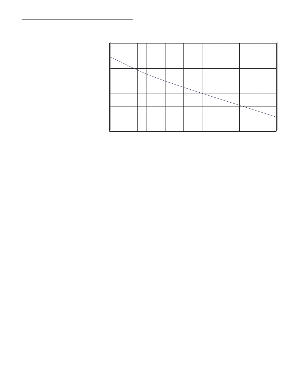
‡
Temperature difference between the IR target surface and the reference probe
are calculated as shown in the graph in Figure 1 on page 8. Note: As the tem
perature of the IR target surface increases, the temperature difference de
creases.
‡
–30°C to 150°C (-22°F to 302°F)
±0.4°C (±0.72°F) [using 1/8" PRT]
able, 50/60 Hz
-
-
Hart Scientific Manual Rev. 180601 7
Page 13
3 Specifications and Environment Conditions
0
C
0.15
0.1
0.05
0
-0.05
delta T °
-0.1
-0.15
-0.2
-30 -10 10 30 50 70 90 110 130 15
Figure 1 Temperature Gradient Between Probe and IR Target Surface at Ambient of 30°C
Reference Probe °C
3.2 Environmental Conditions
Although the instrument has been designed for optimum durability and
trouble-free operation, it must be handled with care. The instrument
should not be operated in an excessively dusty or dirty environment.
Maintenance and cleaning recommendations can be found in the Maintenance section of this manual.
The instrument operates safely under the following conditions:
•
temperature range: 5–50°C (41–122°F)
•
ambient relative humidity: 15–60%
•
pressure: 75kPa–106kPa
•
mains voltage within ±10% of nominal
•
vibrations in the calibration environment should be minimized
•
altitudes less than 2,000 meters
3.3 Warranty
Hart Scientific, Inc. (Hart) warrants this product to be free from defects in
material and workmanship under normal use and service for a period as
stated in our current product catalog from the date of shipment. This war
ranty extends only to the original purchaser and shall not apply to any
-
8 Manual Rev. 180601 9133
Page 14

3 Specifications and Environment Conditions
product which, in Hart’s sole opinion, has been subject to misuse, alter
-
ation, abuse or abnormal conditions of operation or handling.
Software is warranted to operate in accordance with its programmed in
structions on appropriate Hart products. It is not warranted to be error
free.
Hart’s obligation under this warranty is limited to repair or replacement of
a product which is returned to Hart within the warranty period and is de
termined, upon examination by Hart, to be defective. If Hart determines
that the defect or malfunction has been caused by misuse, alteration,
abuse or abnormal conditions or operation or handling, Hart will repair
the product and bill the purchaser for the reasonable cost of repair.
To exercise this warranty, the purchaser must forward the product after
calling or writing Hart for authorization. Hart assumes NO risk for in-tran
sit damage.
For service or assistance, please contact the manufacturer.
Hart Scientific, Inc.
799 East Utah Valley Drive
American Fork, UT 84003-9775
Phone: (801) 763-1600 – Fax: (801) 763-1010
E-mail: support@hartscientific.com
THE FOREGOING WARRANTY IS PURCHASER’S SOLE AND EXCLUSIVE REMEDY AND IS IN LIEU OF ALL OTHER WARRANTIES, EXPRESS OR IMPLIED, INCLUDING BUT NOT LIMITED TO ANY
IMPLIED WARRANTY OR MERCHANTABILITY, OR FITNESS FOR
ANY PARTICULAR PURPOSE OR USE. HART SHALL NOT BE LIABLE
FOR ANY SPECIAL, INDIRECT, INCIDENTAL, OR CONSEQUENTIAL
DAMAGES OR LOSS WHETHER IN CONTRACT, TORT, OR OTHER
-
WISE.
-
Hart Scientific Manual Rev. 180601 9
Page 15

4 Safety Guidelines
•
Operate the instrument in room temperatures between 5–50°C
(41–122° F). Allow sufficient air circulation by leaving at least 6 inches
of space between the instrument and nearby objects.
•
The instrument is a precision instrument. Although is has been de
signed for optimum durability and trouble free operation, it must be
handled with care. The convenient fold-up handle allows one hand
carrying. The instrument should not be operated in excessively wet,
oily, dusty, or dirty environments. It is important to keep the calibration
probe well and the IR target surface clean and clear of any foreign
matter. Do not operate near flammable materials.
•
DO NOT use fluids to clean out the calibration probe well or on the IR
target surface.
•
The instrument can generate extreme temperatures. Precautions
must be taken to prevent personal injury or damage to objects.
•
Use only a grounded AC mains supply of the appropriate voltage to
power the instrument. Refer to Section 3.1, Specifications for power
details.
•
Before initial use, after transport, and anytime the instrument has not
been energized for a “dry-out” period of 1-2 hours before it can be assumed to meet all of the safety requirements of the IEC 1010-1.
•
The instrument is equipped with operator accessible system fuses. If
a fuse blows, it may be due to a power surge or failure of a component.
Replace the fuse once. If the fuse blows a second time, it is likely
caused by failure of a component part. If this occurs, contact Hart Sci
entific Customer Service. Always replace the fuse with one of the
same rating, voltage, and type. Never replace the fuse with one of a
higher current rating.
•
If a main supply power fluctuation occurs, immediately turn off the in
strument. Wait until the power has stabilized before re-energizing the
instrument.
4 Safety Guidelines
-
-
-
Hart Scientific Manual Rev. 180601 11
Page 16

5 Quick Start
5.1 Unpacking
Unpack the calibrator carefully and inspect it for any damage that may
have occurred during shipment. If there is shipping damage, notify the
carrier immediately.
Verify that the following components are present:
•
9133 Calibrator
•
Power Cord
•
User Guide
•
Serial Cable
•
Target Cover
•
9930 Software
5.2 Set Up
Place the calibrator on a flat surface with at least 6 inches of free space
around the instrument. The prop may be swung down to raise the front
of the instrument from a horizontal position. Plug the power cord into a
grounded mains outlet. Observe that the nominal voltage corresponds to
that indicated on the back of the calibrator.
5 Quick Start
Turn on the power to the calibrator by toggling the power switch on. The
fan should begin quietly blowing air through the instrument and the con
troller display should illuminate after 3 seconds. After a brief self-test the
controller should begin normal operation. If the unit fails to operate
please check the power connection.
The thermal electric devices will start operating to bring the temperature
of the calibrator to the set-point temperature and the display will begin to
show the actual target temperature.
Caution:
forms on the target, the IR probe will not indicate the correct tempera
ture.
Use the target cover at temperatures below 5°C. If ice
-
5.3 Power
Plug the instrument power cord into a mains outlet of the proper voltage,
frequency, and current capability. Refer to Section 3.1, Specifications for
Hart Scientific Manual Rev. 180601 13
-
Page 17

5 Quick Start
power details. Turn the instrument on using the rear panel “POWER”
switch. The instrument turns on and begins to heat to the previously pro
grammed temperature set-point. The front panel LED display indicates
the actual instrument temperature.
5.4 Setting the Temperature
Section 8.2 explains in detail how to set the temperature set-point on the
calibrator using the front panel keys. The procedure is summarized here.
1. Press the “SET” button twice to access the set-point value.
2. Press the “UP” or “DOWN” button to change the set-point value.
3. Press the “SET” button to program in the new set-point.
4. Press the “EXIT” button to return to the temperature display.
When the set-point temperature is changed the controller switches the
heater on or off to raise or lower the temperature. The displayed temperature gradually changes until it reaches the set-point temperature. The
target may require 5 to 10 minutes to reach the set-point depending on
the span. Another 5 to 10 minutes is required to stabilize within ±0.1°C
of the set-point. Ultimate stability may take 15 to 20 minutes more of stabilization time.
-
14 Manual Rev. 180601 9133
Page 18

6 Parts and Controls
6.1 Back Panel
6 Parts and Controls
The back panel (Figure 2) consists of the power inlet, power switch, se
-
rial port, and fan.
115 VAC 50/60 Hz 3A
230 VAC 50/60 Hz 1.6A
~
Figure 2 Back Panel
RS-232
115V -3AT 250V
230V -1.6AT 250V
Power Inlet – At the rear of the calibrator is the removable power cord in
let that plugs into an IEC grounded socket.
Power Switch – The power switch is located on the power entry module
(PEM). The PEM also houses the fuses. The PEM allows the unit to be
field switchable for 115 VAC (±10%) or 230 VAC ±10%) operation. (See
Section 7.2, Switching to 230 V Operation.)
Serial Port – A DB-9 male connector is present for interfacing the cali
-
brator to a computer or terminal with serial RS-232 communications.
Fan – The fan inside the calibrator varies in speed. As the target temper
ature increases the fan speed decreases. Slots are provided for airflow.
The area around the calibrator must be kept clear to allow adequate ven
tilation. The airflow is directed out the two sides.
Hart Scientific Manual Rev. 180601 15
-
-
Page 19

6 Parts and Controls
6.2 Front Panel
The front panel (Figure 3) consists of the controller display, controller
key-pad, and target assembly.
SET UPDOWN EXIT
9133
Infrared Calibrator
Figure 3 Front Panel
Controller Display – The digital display displays set and actual tempera-
tures and various calibrator functions, settings, and constants. The display shows temperatures in units according to the selected scale °C or
°F.
Controller Keypad – The four button keypad allows easy setting of the
set-point temperature. The control buttons (SET, DOWN, UP, and EXIT)
are used to set the calibrator temperature set-point, access and set other
operating parameters, and access and set calibration parameters.
Setting the control temperature is done directly in degrees of the current
scale. The control temperature can be set to one-tenth of a degree Cel
sius or Fahrenheit.
The functions of the buttons are as follows:
SET – Used to display the next parameter in a menu and to set parame
ters to the displayed value.
DOWN – Used to decrement the displayed value of parameters.
UP – Used to increment the displayed value.
EXIT – Used to exit from a menu. When the EXIT button is pressed any
changes made to the displayed value are ignored.
16 Manual Rev. 180601 9133
-
-
Page 20

6 Parts and Controls
Target Assembly – The target assembly is 2.25” (57 mm) in diameter
and has an emissive of 0.95.
Hart Scientific Manual Rev. 180601 17
Page 21

7 General Operation
7.1 Changing Display Units
The Model 9133 can display temperature in Celsius or Fahrenheit. The
temperature units are shipped from the factory set to Celsius. There are
two ways to change to Fahrenheit or back to Celsius as described below.
1. Press the “SET” and “UP” buttons simultaneously. The units are
changed.
Or
1. Press the “SET” button three times from the temperature display
to show Un =C
2. Press the “UP” or “DOWN” button to change units.
7.2 Switching to 230 V Operation
The Model 9133 is switchable from 115 VAC to 230 VAC 50/60 Hz. To
change from 115 VAC to 230 VAC follow the steps below.
7 General Operation
1. Unplug the instrument.
2. With a small straight slot screwdriver remove the fuse holder lo-
cated on the rear panel.
3. Replace the two 3 A 250 V fuses with two 1.6 AT 250 V fuses.
4. Replace the fuse holder with the “~” in the display window.
Note: If “~” is not displayed in the window, the unit will not heat or cool.
7.3 Ice Buildup/Purge
To prevent ice buildup on the target at temperatures below 5°C, use the
target cover and/or a dry gas purge. When taking measurements using
the target cover, place the target cover in place and set the set-point tem
perature to the desired temperature, remove the target cover, take a
sample, and replace the cover. When ice forms on the target, change the
unit set-point higher than 5°C to melt the excess ice. When the ice melts
pat the excess water off with a clean dry cloth. Do not wipe the front
plate. If a clean dry cloth is not available, change the set-point to 100°C
or higher, to evaporate the excess water.
Hart Scientific Manual Rev. 180601 19
-
Page 22

7 General Operation
When using a dry gas purge, the instrument will not reach minimum tem
perature. An example of a gas purge is dry nitrogen connected through a
1/8” inner diameter tube to the purge fitting located at the front bottom of
the target. The nitrogen gas is controlled to fill the chamber in front of the
target at a rate that will not allow airflow to affect the target. Note: If the
gas contains any moisture, ice will form on the target.
-
20 Manual Rev. 180601 9133
Page 23

8 Controller Operation
8 Controller Operation
This section discusses in detail how to operate the instrument tempera
ture controller using the front control panel. By using the front panel
key-switches and LED display, the user may monitor the target tempera
ture, adjust the set-point temperature in degrees C or F, monitor the out
put power, adjust the controller proportional band, and program the
operating parameters, program parameters, serial interface configuration,
and the controller calibration parameters. Operation of the functions and
parameters is shown in the flowchart in Figure 4 on page 22. This chart
may be copied for reference.
In the following discussion a button with the word “SET”, “UP”, “DOWN”,
or “EXIT” inside indicates the panel button while the dotted box indicates
the display reading. Explanation of the button or display reading is to the
right of each button or display value.
8.1 Target Temperature
The digital LED display on the front panel allows direct viewing of the actual temperature. This temperature value is what is normally shown on
the display. The units C or F, of the temperature value are displayed at
the right. For example,
100.0 C
The temperature display function may be accessed from any other function by pressing the “EXIT” button.
Target temperature in degrees Celsius
-
-
-
8.2 Temperature Set-point
The temperature set-point can be set to any value within the range and
resolution as given in the specifications.
Setting the temperature involves selecting one of the eight set-points in
memory and then adjusting the set-point value.
8.2.1 Programmable Set-points
The controller stores eight (8) set-point temperatures in memory. The
set-points can be quickly recalled to conveniently set the instrument to a
previously programmed temperature set-point.
To set the temperature, first select the set-point memory. This function is
accessed from the temperature display function by pressing the “SET”
Hart Scientific Manual Rev. 180601 21
Page 24

8 Controller Operation
Display
Temperature
SET
Select Setpoint
Adjust Setpoint
Units °C/°F
Scan On/Off
Scan Rate
EXIT
(2 Seconds)
(2 Seconds)
Operating
Parameters
Menu
SET
HL
Adj.HL
+
SET
DOWN
Displays Set-Point Resistance
+
SET
UP
Tog gl es ° C / ° F
Automatically returns to display
Secondary Functions
+
SET
EXIT
Display Power
Set Proportional Band
Configuration Menu
SET
EXITEXIT
UP
DOWN DOWN
Serial
Interface
Menu
SET
BAUD
Rate
Adjust
BAUD Rate
EXIT
EXIT
Cal
Cal
Menu
Menu
SET
SET
X5
X5
DO NOT CHANGE THESEVALUES. SEE MANUAL
DO NOT CHANGE THESEVALUES. SEE MANUAL
R0
R0
Adj. R0
Adj. R0
ALPHA
ALPHA
Adj. ALPHA
Adj. ALPHA
DELTA
DELTA
UP
DO NOT CHANGE THESEVALUES. SEE MANUAL
DO NOT CHANGE THESEVALUES. SEE MANUAL
Ad j. D ELTA
Ad j. D ELTA
BETA
BETA
Adjust
Adjust
BETA
BETA
Sample
Menu Legend:
Press “SET” to step through the menu and
to store the parameter value.
Press “EXIT” briefly to skip a parameter
without storing the parameter value.
Hold “EXIT”( 2 seconds) to exit the menu
and display the temperature
≈
Period
Adj. Sample
Period
Duplex
Mode
Adj. Duplex
Mode
Linefeed
Adjust
Linefeed
Figure 4 Controller Operation Flow Chart
22 Manual Rev. 180601 9133
Page 25

8 Controller Operation
button. The number of the set-point memory currently being used is
shown at the left on the display followed by the current set-point value.
100.0 C
S
Access set-point memory
1 100.
To change the set-point memory to another preset value press the “UP”
or “DOWN” button.
4 150
Press the “SET” button to display the new selection and access the
set-point value.
S
Accept selected set-point memory
8.2.2 Set-point Value
The set-point value may be adjusted after selecting the set-point memory
and pressing the “SET” button. The set-point value is displayed with the
units, C or F, at the left.
4 120.
Well temperature in degrees Celsius
Set-point memory 1, 100°C currently used
New set-point memory 4, 150°C
Set-point value 4, 120.0°C
If the set-point value does not need to be changed, press the “EXIT” but
ton to resume displaying the instrument temperature. Press the “UP” or
the “DOWN” button to adjust the set-point value.
U
When the desired set-point value is reached press the “SET” button to
accept the new value. If the “EXIT” button is pressed, any changes made
to the set-point are ignored.
S
Hart Scientific Manual Rev. 180601 23
Increment display
125.0
Accept new set-point value
New set-point value
-
Page 26

8 Controller Operation
8.3 Temperature Scale Units
The temperature scale units of the controller can be set by the user to
degrees Celsius (°C) or Fahrenheit (°F). The units are used in displaying
the well temperature, set-point, and proportional band.
Press the “SET” button after adjusting the set-point value to change dis
play units
Un= C
Press the “UP” or “DOWN” button to change the units.
U
Change units
Un = F
Press the “SET” button to accept the new selection and resume display
ing the display temperature.
8.4 Scan
The scan rate can be set and enabled so that when the set-point is
changed the instrument heats or cools at a specified rate, in degrees C
per minute only, until it reaches the new set-point. With the scan disabled
the instrument heats or cools at the maximum possible rate.
8.4.1 Scan Control
The scan is controlled with the scan on/off function that appears in the
main menu after the temperature scale units.
-
Scale units currently selected
New units selected
-
Sc=OFF
Press the “UP” or “DOWN” button to toggle the scan on or off.
Sc=On
Press the “SET” button to accept the present setting and to continue.
S
24 Manual Rev. 180601 9133
Accept scan setting
Scan function off
Scan function on
Page 27

8.4.2 Scan Rate
The next function in the main menu is the scan rate. The scan rate can
be set from .1 to 99.9°C/min. The maximum scan rate however is actually
limited by the natural heating or cooling rate of the instrument.
The scan rate function appears in the main menu after the scan control
function. The scan rate units are in degrees Celsius per minute.
8 Controller Operation
Sr=10.0
Press the “UP” or “DOWN” button to change the scan rate.
Sr=2.0
Press the “SET” button to accept the new scan rate and continue.
S
Accept scan rate
Scan rate in C/min
New scan rate
8.5 Set-point Resistance
To display the Set-point Resistance, press the “SET” and “DOWN” buttons simultaneously when the temperature is displayed. When the “SET”
and “DOWN” buttons are released the temperature is again displayed.
This value is used to calibrate the unit and is not adjustable.
8.6 Temperature Scale Units
To toggle between °C and °F, press the “SET” and “UP” keys simulta
neously when the temperature is displayed.
8.7 Secondary Menu
-
Functions used less often are accessed within the secondary menu.
Press and hold the “SET” and EXIT buttons to access the secondary
menu. The first function in the secondary menu is the heater power dis
play. (See Figure 4 on page 22.)
8.8 Heater Power
The temperature controller controls the temperature of the well by puls
ing the heater on and off. The total power being applied to the heater is
determined by the duty cycle or the ratio of heater on time to the pulse
cycle time. By knowing the amount of heating the user can tell if the in
strument is heating “UP” to the set-point, cooling “DOWN”, or controlling
at a constant temperature. Monitoring the percent heater power lets the
Hart Scientific Manual Rev. 180601 25
-
-
-
Page 28

8 Controller Operation
user know the stability of the well temperature. With good control stability
the percent heating power should not fluctuate more than ±1% within one
minute.
The heater power display is accessed in the secondary menu. Press and
hold the “SET” and “EXIT: buttons. The heater power is displayed as a
percentage of full power.
100.0 C
S+E
SEC
12.0P
To exit out of the secondary menu press and hold the “EXIT” button. To
continue on to the proportional band setting function, press the “SET”
button.
Target temperature
Access heater power in percent
Flashes for secondary menu and then displays
the heater power
Heater power in percent
8.9 Proportional Band
In a proportional controller such as this, the heater output power is proportional to the target temperature over a limited range of temperatures
around the set-point. This range of temperature is called proportional
band. At the bottom of the proportional band, the heater output is 100%.
At the top of the proportional band, the heater output is 0. Thus as the
temperature rises the heater power is reduced. In this way the tempera
ture is maintained at a fairly constant level.
The temperature stability of the instrument depends on the width of the
proportional band. If the band is too wide, the target temperature devi
ates excessively from the set-point due to varying external conditions.
This deviation is caused by the power output changing very little with
temperature and the controller not responding well to changing condi
tions or noise in the system. If the proportional band is too narrow the
temperature may swing back and forth because the controller overreacts
to temperature variations. For best stability control, the proportional band
must be set for the optimum width by the user in any given application.
-
-
-
The optimum proportional band width is set at the factory to about
25.0°C. The user may alter the proportional band width to optimize the
control characteristics for a particular application. However, we recom
mend the proportional band be changed only by knowledgeable person
nel.
26 Manual Rev. 180601 9133
-
-
Page 29

8 Controller Operation
The proportional band width is easily adjusted from the front panel. The
width may be set to discrete values in degrees C or F depending on the
selected units. The proportional band adjustment can be accessed within
the secondary menu. Press the “SET” and “EXIT” buttons to enter the
secondary menu and show the heater power. Then press the “SET” but
ton to access the proportional band.
-
S+E
SEC
12.0P
S
Prob
4.1
To change the proportional band setting press the “UP” or “DOWN” buttons.
U
10.
To store the new setting press the “SET” button. Press the “EXIT” button
to continue without storing the new value.
Access heater power in secondary menu
Flashes for secondary menu and then displays
the heater power
Heater power in percent
Access proportional band
Flashes for proportional band and then displays
the proportional band setting
Proportional band setting
Increment display
New proportional band setting
S
Accept the new proportional band setting
8.10 Controller Configuration
The controller has a number of configuration, operation, and calibration
parameters that are programmable via the front panel. These are ac
cessed from the secondary menu after the proportional band by pressing
the “SET” button. There are three sets of configuration parameters – op
erating parameters, serial interface parameters, and calibration parame
ters. The menus are selected by using the “UP” and “DOWN” buttons and
then pressing the “SET” button.
Hart Scientific Manual Rev. 180601 27
-
-
-
Page 30

8 Controller Operation
8.11 Operating Parameters
The operating parameters menu contains the High Limit parameter. The
operating parameter menu is indicated by,
PAr
The High Limit parameter adjusts the upper set-point temperature limit.
The factory default and maximum are set to 160°C. For safety, a user can
adjust the High Limit parameter down so the maximum temperature
set-point is restricted. Press the “SET” button to enable adjustment of the
High Limit parameter.
HL
H=126
To change to High Limit setting, use the “UP” or “DOWN” button.
H=90
Press the “SET” button to save this setting.
Operating parameters menu
Flashes and then displays the setting
Current HL setting
New High Limit setting
8.12 Serial Interface Parameters
The serial interface parameters menu contains parameters, which determine the operation of the serial interface. The parameters in the menu
are – BAUD rate, sample period, duplex mode, and linefeed. The serial
RS-232 interface parameters menu is indicated by,
SEriAL
Press the “UP” button from the operations Parameters Menu to access
the Serial menu. Press “SET” to enter the menu.
Serial RS-232 interface parameters menu
8.12.1 BAUD Rate
The BAUD rate is the first parameter in the menu. The BAUD rate setting
determines the serial communications transmission rate. The BAUD rate
of the serial communications may be programmed to 300, 600, 1200,
2400, 4800, or 9600. The default setting is 2400 baud.
bAUd
28 Manual Rev. 180601 9133
Flashes and then displays the setting
Page 31

8 Controller Operation
2400 b
Use the “UP” or “DOWN” buttons to change the baud rate setting.
4800 b
Press the “SET” button to store the new setting as the baud rate or press
the “EXIT” button to skip to the next parameter without storing the new
setting.
8.12.2 Sample Period
The sample period is the next parameter in the serial interface parame
ters menu. The sample period is the time period in seconds between
temperature measurements transmitted from the serial interface. If the
sample rate is set to 5, the instrument transmits the current measure
ment over the serial interface approximately every five seconds. The au
tomatic sampling is disabled with a sample period of 0.
SPEr
SP= 1
Use the “UP” or “DOWN” buttons to adjust the setting.
Current BAUD rate
New BAUD rate
-
-
-
Flashes and then displays the setting
Current sample period (seconds)
SP=60
Press the “SET” button to store the new setting as the sample period or
press the “EXIT” button to skip to the next parameter without storing the
new setting.
New sample period
8.12.3 Duplex Mode
The next parameter is the duplex mode. The duplex mode may be set to
full duplex or half duplex. With full duplex any commands received by the
instrument via the serial interface are immediately echoed or transmitted
back to the device of origin. With half duplex the commands are executed
but not echoed.
duPL
d=FULL
Use the “UP” or “DOWN” buttons to adjust the setting.
Hart Scientific Manual Rev. 180601 29
Flashes and then displays the setting
Current duplex mode
Page 32

8 Controller Operation
d=HALF
Press the “SET” button to store the new setting as the duplex mode or
press the “EXIT” button to skip to the next parameter without storing the
new setting.
8.12.4 Linefeed
The final parameter in the serial interface menu is the linefeed mode.
This parameter enables (on) or disables (off) transmission of a linefeed
character (LF, ASCII 10) after transmission of any carriage-return.
LF
LF=On
Use the “UP” or “DOWN” buttons to adjust the setting.
LF=OFF
Press the “SET” button to store the new setting as the linefeed or press
the “EXIT” button to skip to the next parameter without storing the new
setting.
New duplex mode setting
Flashes and then displays the setting
Current linefeed setting
New linefeed setting
8.13 Calibration Parameters
The probe parameters menu contains the parameters, R0, ALPHA,
DELTA, and BETA, which characterize the resistance-temperature rela
tionship of the platinum control probe. These values are set at the factory
and must not be altered. The correct values are important to the accu
racy and proper and safe operation of the instrument. Access to these
parameters is available to the user so that in the event that the controller
memory fails the user may restore these values to the factory settings.
The user should have a list of these constants on the Report of Calibra
tion that ships with the instrument.
Caution: DO NOT change the value of the instrument cali
bration constants from the factory set values. The correct setting of
these parameters is important to the safety and proper operation of
the unit.
The calibration parameters menu is indicated by,
30 Manual Rev. 180601 9133
-
-
-
-
Page 33

8 Controller Operation
CAL
Press the “SET” button five times to enter the menu. The name of the pa
rameter flashes on the display and then the value is displayed. The value
of the parameter may be changed using the “UP” and “DOWN” buttons.
After the desired value is reached press the “SET” button to set the pa
rameter to the new value. Pressing the “EXIT” button causes the parame
ter to be skipped ignoring any changes that may have been made.
8.13.1 R0
This probe parameter refers to the resistance of the control probe at 0°C.
The value of this parameter is set at the factory for best instrument accu
racy.
8.13.2 ALPHA
This probe parameter refers to the average sensitivity of the probe between 0 and 100°C. The value of this parameter is set at the factory for
best instrument accuracy.
8.13.3 DELTA
This probe parameter refers to the curvature of the resistance-temperature relationship or the sensor. The value of this parameter is set at the
factory for best instrument accuracy.
calibration parameters menu
-
-
-
-
8.13.4 BETA
This probe parameter characterizes the low temperatures. The value of
this parameter is set at the factory for best instrument accuracy.
Hart Scientific Manual Rev. 180601 31
Page 34

9 Digital Communication Interface
9NC
9 Digital Communication Interface
The Model 9133 calibrator is capable of communicating with and being
controlled by other equipment through the digital interface. With a digital
interface the instrument may be connected to a computer or other equip
ment. This allows the user to set the instrument temperature, monitor the
temperature, and access any of the other controller functions, all using
remote communications equipment. Communications commands are
summarized in Table 1 on page x.
9.1 Serial Communications
The RS-232 serial interface allows serial digital communications over
fairly long distances (15.24 meters). With the serial interface the user
may access any of the functions, parameters and settings discussed in
Section 8, Controller Operation with the exception of the BAUD rate set
ting. The serial interface operates with eight data bits, one stop bit, and
no parity.
9.1.1 Wiring
The serial communications
cable attaches to the instrument through the DB-9 connector at the back of the
instrument. Figure 5 shows
the pin-out of this connector
and suggested cable wiring.
To eliminate noise, the serial
cable should be shielded with
low resistance between the
connector (DB-9) and the
shield.
RS-232Cable Wiring for
IBM PC and Compatibles
Instrument
Connector
(DB 9-Pin)
1NC
2RxD
3TxD
4NC
5GND
6NC
7RTS
8CTS
9NC
-
Computer (DTE)
Connector
(DB 9-Pin)
1 DCD
2RxD
3TxD
4DTR
5GND
6DSR
7RTS
8CTS
9NC
-
9.1.2 Setup
Before operation, the serial
interface of the instrument
must be set up by program
ming the BAUD rate and
other configuration parame
ters. These parameters are
programmed within the serial
Instrument
Connector
(DB 9-Pin)
1NC
-
2RxD
3TxD
4NC
5GND
-
6NC
7RTS
8CTS
Computer (DTE)
Connector
(DB 25-Pin)
2TxD
3RxD
4RTS
5CTS
6DSR
7GND
8 DCD
20 DTR
Figure 5 Serial Cable Wiring
Hart Scientific Manual Rev. 180601 33
Page 35

9 Digital Communication Interface
interface menu. The serial interface parameters menu is outlined in Sec
tion 8.12.
To enter the serial parameter programming mode first, press the “EXIT”
button while pressing the “SET” button and release to enter the second
ary menu. Press the “SET” button repeatedly until the display reads
“ProbE”. This is the menu selection. Press the “UP” button repeatedly
until the serial interface menu is indicated with “SErIAL”. Finally press the
“SET” button to enter the serial parameter menu. The serial interface pa
rameter menu contains the BAUD rate, the sample rate, the duplex
mode, and the linefeed parameter.
9.1.2.1 BAUD Rate
The BAUD rate is the first parameter in the menu. The display prompts
with the BAUD rate parameter by showing “BAUd”. Press the “SET” but
ton to choose to set the BAUD rate. The current BAUD rate value is dis
played. The BAUD rate of the instrument may be programmed to 300,
600, 1200, or 2400 BAUD. The BAUD rate is pre-programmed to 2400
BAUD. Use “UP” or “DOWN” to change the BAUD rate value. Press the
“SET” button to set the BAUD to the new value or the “EXIT” button to
abort the operation and skip to the next parameter in the menu.
9.1.2.2 Sample Period
The sample period is the next parameter in the menu and prompted with
“SAMPLE”. The sample period is the time period, in seconds, between
temperature measurements transmitted from the serial interface. If the
sample rate is set to 5, the instrument transmits the current measurement over the serial interface approximately every five seconds. The au
tomatic sampling is disabled with a sample period of 0. Press the “SET”
button to choose to set the sample period. Adjust the period with the “UP”
or “DOWN” button and then use the “SET” to set the sample rate to the
displayed value.
-
-
-
-
-
-
9.1.2.3 Duplex Mode
The next parameter is the duplex mode indicated with “dUPL”. The du
plex mode may be set to half duplex (“HALF”) or full duplex (“FULL”). With
full duplex any commands received by the instrument via the serial inter
face are immediately echoed or transmitted back to the device of origin.
With half duplex the commands are executed but not echoed. The default
setting is full duplex. The mode may be changed using “UP” or “DOWN”
and pressing “SET”.
34 Manual Rev. 180601 9133
-
Page 36

9.1.2.4 Linefeed
The final parameter in the serial interface menu is the linefeed mode.
This parameter enables (“On”) or disables (“OFF”) transmission of a line
feed character (LF, ASCII 10) after transmission of any carriage-return.
The default setting is with linefeed on. The mode may be changed using
“UP” or “DOWN” and pressing “SET”.
9.1.3 Serial Operation
Once the cable has been attached and the interface set up properly the
controller immediately begins transmitting temperature readings at the
programmed rate. The set-point and other commands may be sent to the
instrument via the serial interface to set the instrument and view or pro
gram the various parameters. The interface commands are discussed in
Section 9.3, Interface Commands.
9.2 Interface Commands
The various commands for accessing the instrument controller functions
via the digital interfaces are listed in Table 4. These commands are used
with both the RS-232 serial interface and the IEEE-488 GPIB interface. In
either case the commands are terminated with a carriage-return character. The interface makes no distinction between upper and lower case letters, hence either may be used. Commands may be abbreviated to the
minimum number of letters, which determines a unique command. A
command may be used to either set a parameter or display a parameter
depending on whether or not a value is sent with the command following
a “=” character. For example, an “s”<cr> returns the current set-point and
an “s=50.00”<cr> sets the set-point to 50.00 degrees.
9 Digital Communication Interface
-
-
In the following list of commands, characters or date within brackets, “[“
and “]”, are optional. A slash, “/”, denotes alternate characters or data.
Numeric data, denoted by “n”, may be entered in decimal or exponential
notation. Characters are shown in lower case although upper case may
be used. Spaces may be added within command strings and are simply
ignored. Backspace (BS, ASCII 8) may be used to erase the previous
character. A terminating CR is implied with all commands.
Hart Scientific Manual Rev. 180601 35
Page 37

9 Digital Communication Interface
Table 2 Controller Communications Commands
Command Description
Command
Format
Command
Example Returned
Returned
Example
Acceptable
Values
Display Temperature
Read current set-point s[etpoint] s set: 999.9 {C or F} set: 100.00 C
Set current set-point to n s[etpoint]=n s=200.0 Instrument Range
Read temperature t[emperature] t t: 999.9 {C or F} t: 55.6 C
Read temperature units u[nits] u u: x u: C
Set temperature units: u[nits]=c/f
Set temperature units to Celsius
Set temperature units to
Fahrenheit
Read scan mode sc[an] sc scan: {ON or OFF} scan:ON
Set scan mode sc[an]=on/off sc=on ON or OFF
Read scan rate sr[ate] sr srat: 99.9 {C or F}/min srat:12.4C/min
Set scan rate sr[ate]=n sr=1.1 .1 to 99.9
u[nits]=c u=c
u[nits]=f u=f
C or F
Secondary Menu
Read proportional band setting pr[opband] pr pb: 999.9 pb: 15.9
Set proportional band to
Read heater power
(duty cycle)
n
pr[opband]=n pr=8.83 Depends on
po[wer] po po: 999.9 po: 1.0
Configuration
Configuration Menu
Operating Parameters Menu
Read high limit hl hl hl:999 hl:126
Set high limit hl=n hl=90 50–160
Serial Interface Menu
Read serial sample setting sa[mple] sa sa: 9 sa: 1
n
Set serial sampling setting to
seconds
Set serial duplex mode: du[plex]=f[ull]/h[alf]
Set serial duplex mode to full
Set serial duplex mode to half
Set serial linefeed mode: lf[eed]=on/of[f]
Set serial linefeed mode to on
Set serial linefeed mode to off
Calibration Menu
Read R0 calibration parameter r[0] r r0: 999.999 r0: 100.578
Set R0 calibration parameter to
Read ALPHA calibration parameter al[pha] al al: 9.9999999 al: 0.0038573
Set ALPHA calibration parameter to
Read DELTA calibration parameter de[lta] de de:9.99999 de: 1.507
Set DELTA calibration parameter de[lta]=n de=1.3742 0–3.0
Read BETA calibration parameter be[ta] be be:9.999 be:0.342
Set BETA calibration parameter be[ta]=n be=0.342 –100.0 to 100.0
sa[mple]=n sa=0 0 to 999
du[plex]=f[ull] du=f
du[plex]=h[alf] du=h
lf[eed]=on lf=on
lf[eed]=of[f] lf=of
n
r[0]=n r=100.324 90 to 110
n
al[pha]=n al=0.0038433 .002 to .005
FULL or HALF
ON or OFF
36 Manual Rev. 180601 9133
Page 38

Controller Communications Commands continued
9 Digital Communication Interface
Command
Command Description
Functions not on menu
Read firmware version number *ver[sion] *ver ver.9999,9.99 ver.9133,1.00
Read structure of all commands h[elp] h list of commands
Read all operating parameters all all list of parameters
Legend:
Note:
Format
[] Optional Command data
{} Returns either information
n Numeric data supplied by user
9 Numeric data returned to user
x Character data returned to user
When DUPLEX is set to FULL and a command is sent to READ, the command is returned followed by a carriage return
and linefeed. Then the value is returned as indicated in the RETURNED column.
Command
Example Returned
Returned
Example
Acceptable
Values
Hart Scientific Manual Rev. 180601 37
Page 39

10 Calibration Procedure
Sometimes the user may want to calibrate the instrument to improve the
temperature set-point accuracy. Calibration is done by adjusting the con
troller probe calibration constants R0, ALPHA, DELTA, and BETA so that
the temperature of the calibrator as measured with a standard thermom
eter agrees more closely with the set-point. The thermometer used must
be able to measure the well temperature with higher accuracy than the
desired accuracy of the calibrator. By using a good thermometer and fol
lowing this procedure the instrument can be calibrated to an accuracy of
better than 0.5°C up to 150°C.
10.1 Calibration Points
10 Calibration Procedure
-
-
-
In calibrating the instrument, R0, ALPHA, DELTA, and BETA, are ad
justed to minimize the set-point error at each of three different tempera
tures. Any three appropriately separated temperatures may be used for
the calibration. Improved results can be obtained for shorter ranges when
using temperatures that are just within the most useful operating range of
the instrument. The farther apart the calibration temperatures, the larger
the calibrated range. However, the calibration error will also be greater
over that range. If, for instance, –20°C to 100°C is chosen as the calibration range, the calibrator may achieve an accuracy of ±0.3°C over that
range (–20 to 100°C). Choosing a range of 50°C to 90°C may allow the
calibrator to have a better accuracy of maybe ±0.2°C over the narrower
range but, outside that range, the accuracy may be only ±1.5°C.
10.2 Calibration Procedure
1. Choose four set-points to use in the calibration of the R0, AL
PHA, DELTA, and BETA parameters. These set-points are gener
ally –25°C, 0°C, 60°C, and 125°C but other set-points may be
used if desired or necessary.
2. Set the instrument to the low set-point. When the instrument
reaches the set-point and the display is stable, wait 15 minutes
or so and then take a reading. Sample the set-point resistance
by holding down the “SET” key and pressing the “DOWN” key.
Write these values down as T
and R1respectively.
1
-
-
-
-
3. Repeat step 2 for the other three set-points recording them as
T
, R1, T2, R2, T3, R3, T4and R4respectively.
1
Hart Scientific Manual Rev. 180601 39
Page 40

10 Calibration Procedure
10.2.1 Compute DELTA
4. Using the recorded data, calculate new values for R0, ALPHA,
DELTA, and BETA parameters using the equations given below.
AT T
=−
43
BT T
=−
32
TTTT
C
4433
=
100
TTTT
3322
D
=
100
ER R
=−
43
FR R
=−
32
delta
T
R
AF BE
=
DE CF
- Measured temperature using the reference thermometer
1-3
- Value of R from the 9133 display (Press SET and DOWN at the
1-3
1
−
100 100
1
−
100 100
−
−
−
−
1
−
100
1
−
100
same time)
Where
T
and R1are the measured temperature and resistance at –25°C
1
T
and R2are the measured temperature and resistance at 0°C
2
T
and R3are the measured temperature and resistance at 60°C
3
T
and R4are the measured temperature and resistance at 125°C
4
10.2.2 Compute R0 and ALPHA
TT
=+
a T delta
12
=+
a T delta
34
Ra Ra
rzero
alpha
41 2 3
=
=
Ra Ra
22
100
TT
44
100
−
aa
−
13
RR
−
24
−
41 2 3
40 Manual Rev. 180601 9133
1
−
100
1
−
100
Page 41

delta is the new value of DELTA computed above.
10.2.3 Compute BETA
T
1
x
=
y
=
beta
Where T1and R1are the measured temperature and resistance at
–25.00°C and alpha, rzero, and delta are the new values of ALPHA, R0,
and DELTA calculated above.
Program the new values for R0 (rzero), ALPHA (alpha), DELTA (delta),
and BETA (beta) into the instrument with the following steps.
1. Reference Section 8.13 to display R0.
1
−
100
T
1
100
=+−−
()()
1
alpha x y
()()()
10 Calibration Procedure
R
1
3
T
xy
delta
1
2
3
y
r
0
alpha x y
()()
3
()
2. Press the “SET” button then use the “UP” or “DOWN” buttons un-
til the correct numerical setting is displayed. Press the “SET” button to accept the new value.
3. Repeat step 2 for ALPHA, DELTA, and BETA.
10.2.4 Accuracy and Repeatability
Check the accuracy of the instrument at various points over the cali
brated range. If the instrument does not pass specification at all
set-points, repeat the Calibration Procedure.
-
Hart Scientific Manual Rev. 180601 41
Page 42

11 Maintenance
•
The instrument has been designed with the utmost care. Ease of op
eration and simplicity of maintenance have been a central theme in
the product development. Therefore, with proper care the instrument
should require very little maintenance.Avoid operating the instrument
in an oily, wet, dirty, or dusty environment.
•
Ice will build up on the target surface over a period of time if the unit is
operated at sub-zero temperatures, allowing water to pool in the well
at temperatures above 0.0°C. The user needs to drain the water build
up after every use. To drain the water build up, set the instrument to a
temperature above 100°C for a period of one hour causing the water
to evaporate.Wipe any remaining water witha dry nonabrasive cloth.
•
If the outside of the instrument becomes soiled, it may be wiped clean
with a damp cloth and mild detergent. DO NOT use harsh chemicals
on the surface, which may damage the paint or target.
•
It is important to keep the well and target surface of the instrument
clean and clear of any foreign matter.
•
The instrument should be handled with care. Avoid knocking or dropping the instrument.
•
If a hazardous material is split on or inside the equipment, the user is
responsible for taking the appropriate decontamination steps as outlined by the national safety council with respect to the material.
•
If the mainssupply cord becomesdamaged, replace itwith a cordwith
the appropriate gauge wire for the current of the unit. If there are any
questions, call Hart ScientificCustomer Service for more information.
•
Before using any cleaning or decontamination method except those
recommended by Hart, users should check with Hart Scientific Cus
tomer Service to be sure that the proposed method does not damage
the equipment.
•
If the instrument is usedin a manner not in accordance with the equip
ment design, the operation of the unit may be impaired or safety haz
ards may arise.
11 Maintenance
-
-
-
-
Hart Scientific Manual Rev. 180601 43
Page 43

12 Troubleshooting
12 Troubleshooting
This section contains information on troubleshooting, CE Comments, and
a wiring diagram.
12.1 Troubleshooting Problems, Possible Causes,
and Solutions
In the event that the instrument appears to function abnormally, this sec
tion may help to find and solve the problem. Several possible problem
conditions are described along with likely causes and solutions. If a prob
lem arises, please read this section carefully and attempt to understand
and solve the problem. If the problem cannot otherwise be solved, con
tact Hart Scientific Customer Service for assistance (1-801-763-1600).
Be sure to have the model number and serial number of your instrument
available.
Problem Possible Causes and Solutions
Incorrect temperature reading
Blank display after
mains power ap
plied
Incorrect R0, ALPHA, DELTA, and BETA parameters.
Find the value for R0, ALPHA, DELTA, and BETA on the
Report of Calibration that was shipped with the instrument.
Reprogram the parameters into the instrument (see Section 8.13, Calibration Parameters). Allow the instrument to
stabilize and verify the accuracy of the temperature reading.
Controller locked up. The controller may have locked up
due to a power surge or other aberration. Initialize the sys
tem by performing the Factory Reset Sequence.
Factory Reset Sequence. Hold the SET and EXIT buttons
down at the same time while powering up the instrument.
The instrument displays shows ‘-init-‘, the model number,
and the firmware version. Each of the controller parameters
and calibration constants must be reprogrammed. The val
ues can be found on the Report of Test that was shipped
with the instrument.
Blown fuse. A fuse may have blown due to a power surge
-
or failure of a component. Replace the fuse once. If the
fuse blows a second time, it is likely caused b the failure of
a component. Always replace the fuse with one of the
same rating, voltage, and type. Never replace the fuse with
one of a higher current rating.
-
-
-
-
Hart Scientific Manual Rev. 180601 45
Page 44

12 Troubleshooting
Problem Possible Causes and Solutions
The Instrument
heats or cools too
quickly or too
slowly
The display shows
any of the follow
ing: err 1 , err
2 , err 3 , err 4
, err 5, Err 6,
or Err 7
Temperature cannot be set above a
certain point
Ice buildup
Incorrect scan and scan rate settings. The scan and
scan rate settings may be set to unwanted values. Check
the Scan and Scan Rate settings. The scan may be off (if
the unit seems to be responding too quickly). The scan
may be on with the Scan Rate set low (if unit seems to be
responding too slowly).
Controller problem. The error messages signify the fol
-
lowing problems with the controller.
Err 1 - a RAM error
Err 2 - a NVRAM error
Err 3 - a Structure error
Err 4 - an ADC setup error
Err 5 - an ADC ready error
Err 6 – a defective control sensor
Err 7 – a heater error
Initialize the system by performing the Factory Reset Se
quence describe above.
Incorrect High Limit parameter. The High Limit parameter may be set below 150°C. Check this value as described
in Section 8.11, Operating Parameters.
At temperatures below 5°C, use the target cover and/or
a gas purge. When taking measurements using the target
cover, place the target cover in place and set the set-point
to the desired temperature, remove the target cover, take a
sample, and replace the cover. When ice forms on the target, change the set-point higher than 5°C to melt the excess ice. When the ice melts pat the excess water off with
a clean dry cloth. Do not wipe the front plate. If a clean
dry cloth is not available, change the set-point to 100°C or
higher, to evaporate the excess water.
-
-
Use a dry gas purge. When using a dry gas purge, the in
strument will not reach minimum temperature. An example
of a dry gas purge is dry nitrogen connected through a 1/8”
inner diameter tube to the purge fitting located at the front
bottom of the target. The nitrogen gas is controlled to fill
the chamber in front of the target at a rate that will not allow
airflow to affect the target. Note: If the gas contains any
moisture, ice will form on the target.
46 Manual Rev. 180601 9133
-
Page 45

Problem Possible Causes and Solutions
The IR probe does
not read what the
IR heat source in
dicates
Emissivity is not the same as the IR probe and target.
Adjust the IR gun or use a look up table from the IR probe
-
manufacturer.
Ice is on the target. Heat the unit above 5°C and remove
the water.
Ambient light may change the reading of the IR probe.
Get closer to the target. A channeling tube may remove
some external environmental factors.
The laser indicator (red dot) is not the actual surface
center of the IR probe (field of measurement. Check the
proper use of the instrument in the IR probe manual. The
field of measurement changes with distance.
There is a difference between the display temperature
and the IR heat source target (temperature gradient).
The closer to ambient the target is, the lower the error will
be. See Figure 1, Temperature Gradient Between Reference Probe and target Surface.
IR probe is reading incorrectly (optic problems) or may
be within its given specifications (1-10°C). Check the
heat source with a known good IR probe.
12 Troubleshooting
IR heat source is out of calibration. Use an external reference.
12.2 Comments
12.2.1 EMC Directive
Hart Scientifics’ equipment has been tested to meet the European Elec
tromagnetic Compatibility Directive (EMC Directive, 89/336/EEC). The
Declaration of Conformity for your instrument lists the specific standards
to which the unit was tested.
12.2.2 Low Voltage Directive (Safety)
In order to comply with the European Low Voltage Directive (73/23/EEC),
Hart Scientific equipment has been designed to meet the IEC 1010-1
(EN 61010-1) and the IEC 1010-2-010 (EN 61010-2-010) standards.
Hart Scientific Manual Rev. 180601 47
-
Page 46

12 Troubleshooting
12.3 Wiring Diagram
D
C
B
1
2
A
A
REV
h 84003
Uta
,
Utah Valley Drive
t
(801) 763-1600
799 Eas
American Fork
SHEET
-2W??
1
B033
WG NO
D
9133 Wiring
64841
CAGECODE
C
TITLE
SIZE
SCALE
2/26/2001
SDM
2
3
4
D
B
A
3
4
Figure 6 Wiring Diagram
48 Manual Rev. 180601 9133
 Loading...