

Page 1

Hart Scientific
9112A
Calibration Furnace
User’s Guide
Rev. 5B2901
Page 2

Fluke Corporation, Hart Scientific Division
799 E. Utah Valley Drive • American Fork, UT 84003-9775 • USA
Phone: +1.801.763.1600 • Telefax: +1.801.763.1010
E-mail: support@hartscientific.com
www.hartscientific.com
Subject to change without notice. • Copyright © 2005 • Printed in USA
Rev. 5B2901
Page 3

Table of Contents
1 Before You Start . . . . . . . . . . . . . . . . . . . . . . . . . . 1
1.1 Symbols Used . . . . . . . . . . . . . . . . . . . . . . . . . . . . 1
1.2 Safety Information . . . . . . . . . . . . . . . . . . . . . . . . . . 2
1.2.1 WARNINGS . . . . . . . . . . . . . . . . . . . . . . . . . . . . . . . . . . . 2
1.2.2 Cautions . . . . . . . . . . . . . . . . . . . . . . . . . . . . . . . . . . . . . 4
1.3 Authorized Service Centers. . . . . . . . . . . . . . . . . . . . . . 5
2 Introduction . . . . . . . . . . . . . . . . . . . . . . . . . . . . 9
3 Specifications and Environmental Conditions . . . . . . . . . 11
3.1 Specifications . . . . . . . . . . . . . . . . . . . . . . . . . . . . 11
3.2 Environmental Conditions. . . . . . . . . . . . . . . . . . . . . . 11
3.3 Warranty . . . . . . . . . . . . . . . . . . . . . . . . . . . . . . . 11
4 Installation . . . . . . . . . . . . . . . . . . . . . . . . . . . . 13
4.1 Unpacking & Inspection . . . . . . . . . . . . . . . . . . . . . . 13
4.2 Location . . . . . . . . . . . . . . . . . . . . . . . . . . . . . . . 13
4.3 “Dry-out” Period . . . . . . . . . . . . . . . . . . . . . . . . . . 14
4.4 Power . . . . . . . . . . . . . . . . . . . . . . . . . . . . . . . . 14
4.5 Equilibration Block Assembly Installation . . . . . . . . . . . . . 14
4.6 Probe Installation . . . . . . . . . . . . . . . . . . . . . . . . . . 14
5 Parts and Controls . . . . . . . . . . . . . . . . . . . . . . . . 17
5.1 Front View. . . . . . . . . . . . . . . . . . . . . . . . . . . . . . 17
5.1.1 Temperature Controller . . . . . . . . . . . . . . . . . . . . . . . . . . . . . 17
5.1.2 Over Temperature Cutout . . . . . . . . . . . . . . . . . . . . . . . . . . . . 18
5.1.3 Power and Heater Switches . . . . . . . . . . . . . . . . . . . . . . . . . . . 18
5.2 Heater Assembly . . . . . . . . . . . . . . . . . . . . . . . . . . 19
5.2.1 Equilibration Block Assembly . . . . . . . . . . . . . . . . . . . . . . . . . 19
5.2.2 Temperature Control and Cutout Sensor . . . . . . . . . . . . . . . . . . . . 20
5.3 Back View . . . . . . . . . . . . . . . . . . . . . . . . . . . . . . 21
5.3.1 The Power Cable . . . . . . . . . . . . . . . . . . . . . . . . . . . . . . . . 21
5.3.2 Nomenclature . . . . . . . . . . . . . . . . . . . . . . . . . . . . . . . . . . 21
5.3.3 Fuses . . . . . . . . . . . . . . . . . . . . . . . . . . . . . . . . . . . . . . 21
6 Operation . . . . . . . . . . . . . . . . . . . . . . . . . . . . . 23
6.1 Overview . . . . . . . . . . . . . . . . . . . . . . . . . . . . . . 23
i
Page 4

6.2 Operating the Furnace . . . . . . . . . . . . . . . . . . . . . . . . 23
7 Digital Communication Interface . . . . . . . . . . . . . . . . 25
8 Maintenance . . . . . . . . . . . . . . . . . . . . . . . . . . . 27
9 Appendix A - Material Safety Data Sheets (MSDS) . . . . . . 29
ii
Page 5

Figures
Figure 1 Front View . . . . . . . . . . . . . . . . . . . . . . . . . . . . . . . . 17
Figure 2 Sectional Side View . . . . . . . . . . . . . . . . . . . . . . . . . . . 19
Figure 3 Back View . . . . . . . . . . . . . . . . . . . . . . . . . . . . . . . . 20
Figure 4 RS-232 Cable Wiring . . . . . . . . . . . . . . . . . . . . . . . . . . 25
iii
Page 6
1 Before You Start
1.1 Symbols Used
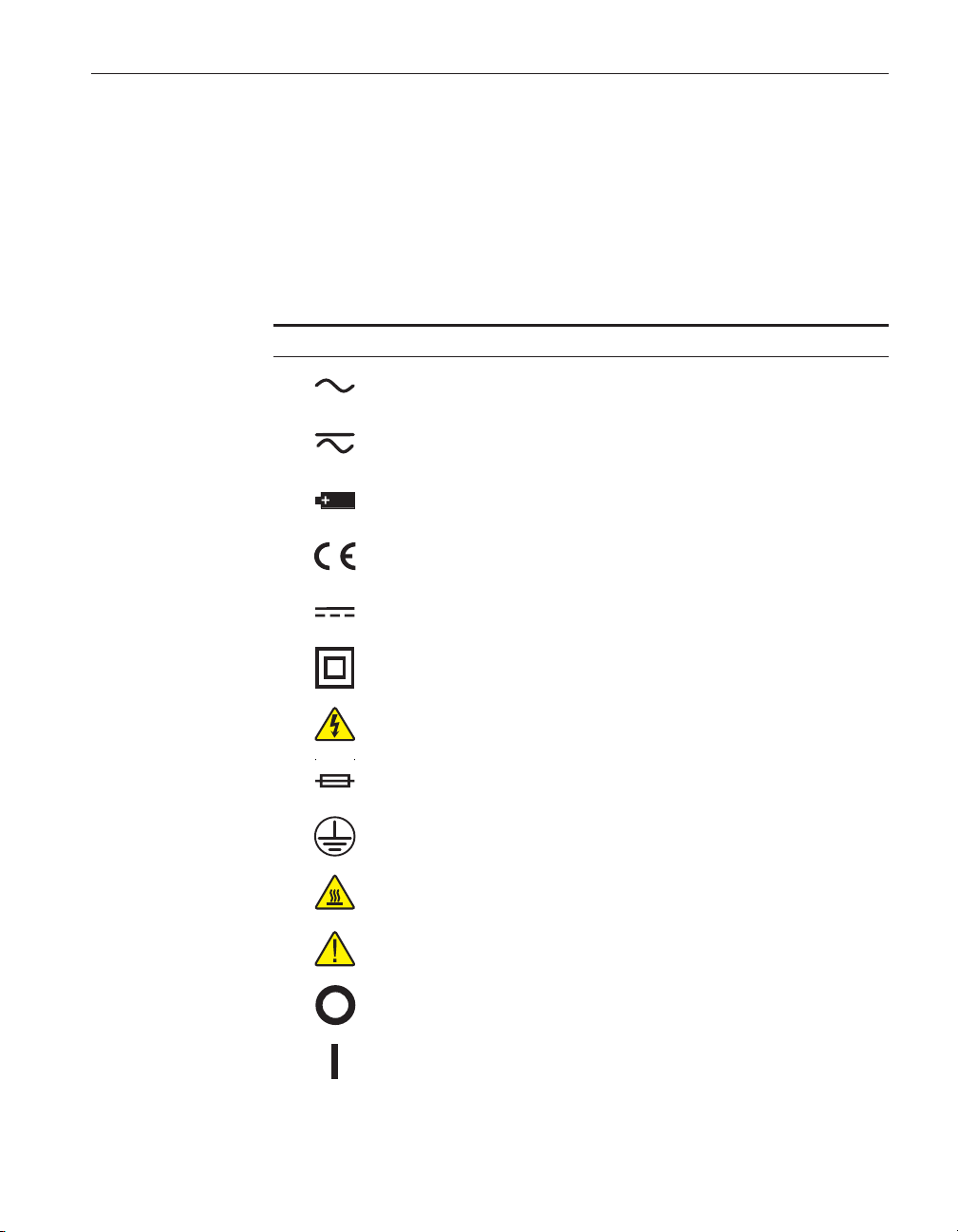
Table 1 lists the International Electrical Symbols. Some or all of these symbols
may be used on the instrument or in this manual.
Tabl e 1 International Electrical Symbols
Symbol Description
AC (Alternating Current)
AC-DC
Battery
CE Complies with European Union Directives
1 Before You Start
Symbols Used
DC
Double Insulated
Electric Shock
Fuse
PE Ground
Hot Surface (Burn Hazard)
Read the User’s Manual (Important Information)
Off
On
1
Page 7
9112A Calibration Furnace
User’s Guide
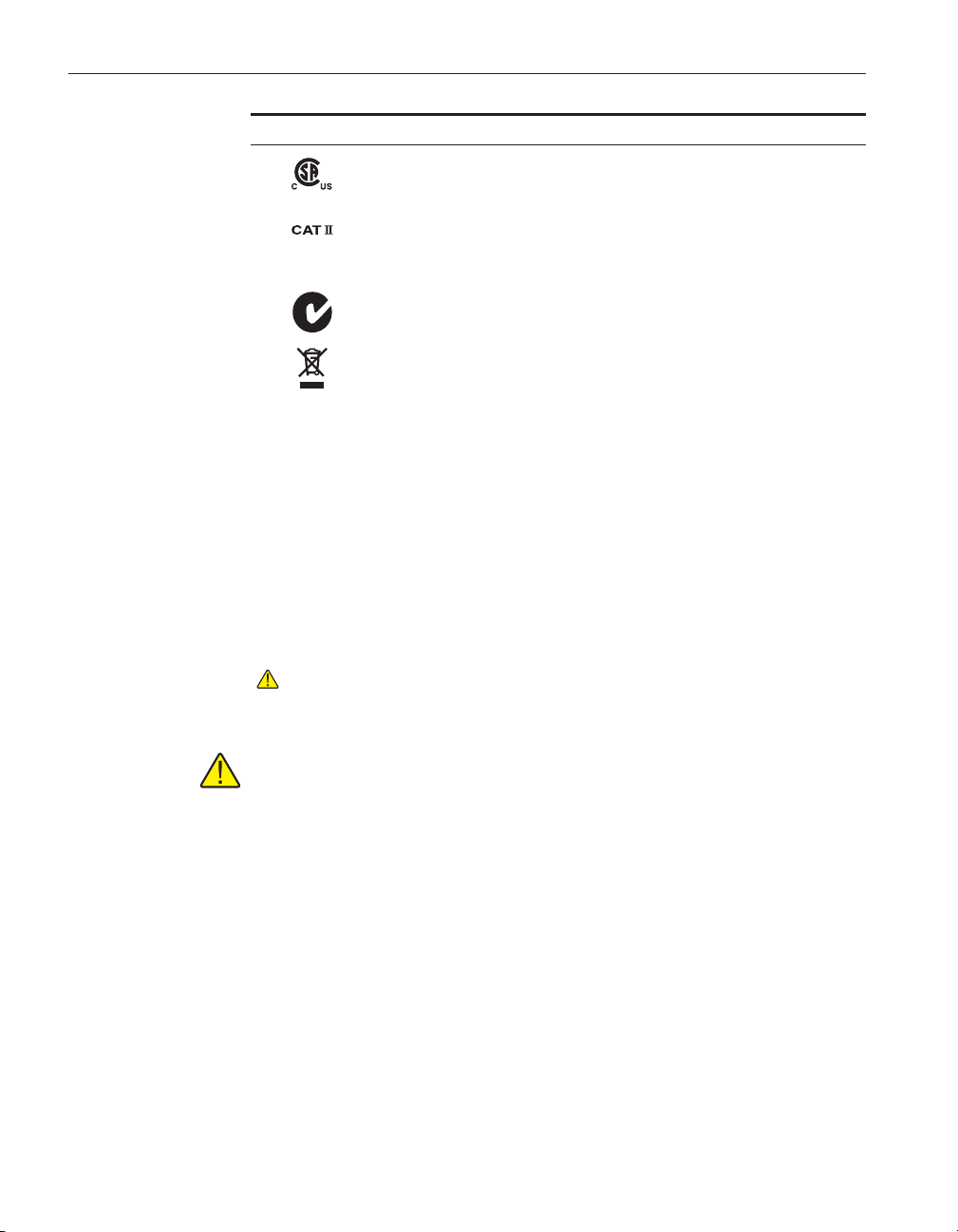
Symbol Description
Canadian Standards Association
OVERVOLTAGE (Installation) CATEGORY II, Pollution Degree 2 per IEC1010-1 re
fers to the level of Impulse Withstand Voltage protection provided. Equipment of
OVERVOLTAGE CATEGORY II is energy-consuming equipment to be supplied from
the fixed installation. Examples include household, office, and laboratory appliances.
C-TIC Australian EMC Mark
The European Waste Electrical and Electronic Equipment (WEEE) Directive
(2002/96/EC) mark.
1.2 Safety Information
Use this instrument only as specified in this manual. Otherwise, the protection
provided by the instrument may be impaired.
The following definitions apply to the terms “Warning” and “Caution”.
• “WARNING” identifies conditions and actions that may pose hazards to
the user.
• “CAUTION” identifies conditions and actions that may damage the instrument being used.
1.2.1
WARNINGS
To avoid personal injury, follow these guidelines.
-
DISCLAIMER: Hart Scientific manufactures instruments for the purpose
of temperature calibration. Instruments used for applications other than
calibration are used at the discretion and sole responsibility of the cus
tomer. Hart Scientific cannot accept any responsibility for the use of in
-
-
struments for any application other than temperature calibration.
GENERAL
Appropriate personal safety protection should be worn by the operator at all
times while using the furnace.
DO NOT use the instrument for any application other than calibration work.
The instrument was designed for temperature calibration. Any other use of the
unit may cause unknown hazards to the user.
DO NOT use the unit in environments other than those listed in the user’s
guide.
Completely unattended operation is not recommended.
2
Page 8

1 Before You Start
Safety Information
Follow all safety guidelines listed in the user’s manual.
Calibration Equipment should only be used by Trained Personnel.
If this equipment is used in a manner not specified by the manufacturer, the
protection provided by the equipment may be impaired or safety hazards may
arise.
Inspect the instrument for damage before each use. DO NOT use the instrument
if it appears damaged or operates abnormally.
Before initial use, or after transport, or after storage in humid or semi-humid
environments, or anytime the instrument has not been energized for more than
10 days, the instrument needs to be energized for a “dry-out” period of 2 hours
before it can be assumed to meet all of the safety requirements of the IEC
1010-1. If the product is wet or has been in a wet environment, take necessary
measures to remove moisture prior to applying power such as storage in a low
humidity temperature chamber operating at 50°C for 4 hours or more.
The instrument is intended for indoor use only.
BURN HAZARD
High temperatures may be present in this equipment. Fires and severe burns
may result if personnel fail to observe safety precautions.
The furnace generates extreme temperatures. Precautions must be taken to prevent personal injury or damage to objects. Probes may be extremely hot when
removed from the furnace. Cautiously handle probes to prevent personal injury.
Carefully place probes on a heat resistant surface rack until they are at room
temperature.
DO NOT lift the back of this instrument with the equilibration block in place.
The equilibration block will fall out of the instrument.
DO NOT operate near flammable materials. Extreme temperatures could ignite
the flammable material.
Use of this instrument at HIGH TEMPERATURES for extended periods of
time requires caution.
DO NOT touch the well access cover of the instrument, it is extremely hot.
For compliance with IEC 1010-1, it is recommended that the cutout mode al
ways be set to the manual mode requiring user intervention to reset the
instrument.
Take extreme care in handling hot probes. The extreme temperatures generated
in a furnace of this type can cause serious personal injury. Do not touch them
on external surfaces of the furnace or set them on any other surfaces unable to
withstand those temperatures. A fire hazard exists. Do not touch the access tube
end plate or severe burns can result.
3
Page 9

9112A Calibration Furnace
User’s Guide
ELECTRICAL HAZARD
These guidelines must be followed to ensure that the safety mechanisms in this
instrument will operate properly. This instrument must be plugged into a 230
VAC (± 10%) 50/60 Hz only electric outlet. The power cord of the instrument
is equipped with a three-pronged grounding plug for your protection against
electrical shock hazards. It must be plugged directly into a properly grounded
three-prong receptacle. The receptacle must be installed in accordance with lo
cal codes and ordinances. or adapter plug. Additionally, the instrument has a
Permanent Earth Ground that must be connected during use. DO NOT use an
extension cord Consult a qualified electrician.
Always replace the power cord with an approved cord of the correct rating and
type. If you have questions, contact a Hart Scientific Authorized Service Center
(see Section 1.3).
The instrument is not equipped with easily accessible fuses. The fuses are lo
cated inside the control drawer. We do not recommend replacing the fuses with
out calling a Hart Scientific Authorized Service Center first.
High voltage is used in the operation of this equipment. Severe injury or death
may result if personnel fail to observe the safety precautions. Before working
inside the equipment, turn off the power and disconnect the power cord.
Always ensure that the equilibration block ground is connection prior to use of
the instrument.
-
-
-
1.2.2
Cautions
Always operate this instrument at room temperature between 41°F and 104°F
(5°C to 40°C). Allow sufficient air circulation by leaving at least 18 inches (45
cm) of clearance around the instrument. DO NOT place instrument in a corner
or block the back of the instrument. Extreme temperatures are emitted from the
back and front of the furnace. Allow sufficient space in front of the furnace to
work and to insert and remove the probes.
Read Section 4, Installation, before placing the instrument into service.
DO NOT use fluids to clean out the well. Fluids could leak into and damage the
instrument.
Never introduce any foreign material into the probe hole of the insert. Fluids,
etc. can leak into the instrument causing damage.
DO NOT change the values of the calibration constants from the factory set
values. The correct setting of these parameters is important to the safety and
proper operation of the unit.
Read and understand the controller operation prior to operating the instrument.
The controller manufacturer’s manual is included with the instrument.
DO NOT operate this instrument in an excessively wet, oily, dusty, or dirty
environment.
4
Page 10

1 Before You Start
Authorized Service Centers
The unit is a precision instrument. Although it has been designed for optimum
durability and trouble free operation, it must be handled with care.
Most probes have handle temperature limits. Be sure that the probe handle tem
perature limit is not exceeded in the air above the instrument.
The instrument and any thermometer probes used with it are sensitive instru
ments that can be easily damaged. Always handle these devices with care. Do
not allow them to be dropped, struck, stressed, or overheated.
When calibrating PRTs always follow correct calibration procedure and cali
brate from high temperatures to low temperatures with the appropriate triple
point of water checks. Never immerse a wet or cold PRT into a bath filled with
hot medium. Severe damage to the PRT may result as well as personal injury to
the calibration technician.
This furnace is not designed to be portable. Therefore, moving the furnace once
it has been installed should be kept to a minimum. To safely move the furnace,
two people are required. One person should lift the furnace at each end of the
furnace, place their hand under the control drawer, and lift simultaneously be
ing careful not to tip. Ensure that the furnace is de-energized and cooled to less
then 100°C. Remove the equilibration block prior to moving. The equilibration
block can damage the fused silica tube that is extremely fragile.
The control probe must be inserted properly in the instrument and plugged into
the socket at the back of the furnace. DO NOT operate the furnace without the
control probe properly inserted and attached. The furnace will not operate correctly without the control probe. Injury to operating personnel and permanent
damage to the furnace could occur.
Components and heater lifetimes can be shortened by continuous high temperature operation.
If a mains supply power fluctuation occurs, immediately turn off the furnace.
Power bumps from brown-outs and black-outs can damage the instrument. Wait
until the power has stabilized before re-energizing the furnace.
The probe and the block may expand at different rates. Allow for probe expan
sion inside the well as the block heats. Otherwise, the probe may become stuck
in the well.
Be aware that the equilibration block expands as the furnace heats. It will ex
tend beyond the front of the furnace at high temperatures anywhere from ¼ to
approximately ½ inch. This is normal and is due to thermal expansion.
Take care that all sensors used as references or being calibrated in the furnace
are capable of withstanding the desired temperature range to be used.
-
-
1.3 Authorized Service Centers
Please contact one of the following Authorized Service Centers to coordinate
service on your Hart product:
5
Page 11

9112A Calibration Furnace
User’s Guide
Hart Scientific, Inc.
Fluke Nederland B.V.
799 E. Utah Valley Drive
American Fork, UT 84003-9775
USA
Phone: +1.801.763.1600
Telefax: +1.801.763.1010
E-mail: support@hartscientific.com
Customer Support Services
Science Park Eindhoven 5108
5692 EC Son
NETHERLANDS
Phone: +31-402-675300
Telefax: +31-402-675321
E-mail: ServiceDesk@fluke.nl
Fluke Int'l Corporation
Service Center - Instrimpex
Room 2301 Sciteck Tower
22 Jianguomenwai Dajie
Chao Yang District
Beijing 100004, PRC
CHINA
Phone: +86-10-6-512-3436
Telefax: +86-10-6-512-3437
E-mail: xingye.han@fluke.com.cn
Fluke South East Asia Pte Ltd.
Fluke ASEAN Regional Office
Service Center
60 Alexandra Terrace #03-16
The Comtech (Lobby D)
118502
SINGAPORE
6
Page 12

1 Before You Start
Authorized Service Centers
Phone: +65 6799-5588
Telefax: +65 6799-5588
E-mail: antng@singa.fluke.com
When contacting these Service Centers for support, please have the following
information available:
Model Number
•
Serial Number
•
Voltage
•
Complete description of the problem
•
7
Page 13

2 Introduction
The 9112A Calibration Furnace was designed specifically for calibrating PRTs,
fiber optic sensors and thermocouples at higher temperature ranges up to
1100°C. The furnace utilizes an equilibration block capable of making compar
ison measurements on multiple probes. The standard equilibration block is
sized for ¼ inch probes, however, custom options are possible. Temperature
stability is better than ± 0.1°C throughout the range and the gradient between
wells at full insertion is less than 0.5°C (± 0.25°C).
The temperature control system utilizes a digital controller with a Type K ther
mocouple control sensor and RS-232 interface. The controller displays the set
temperature and the actual temperature simultaneously. The display shows tem
perature to the nearest degree in °C or °F (shipped in °C). The temperature is
set with convenient up and down buttons on the front panel.
Sensors being calibrated as well as the furnace itself are protected from exces
sive temperature with an over-temperature cutout. The cutout is easily adjusted
from the front panel. This device is relay operated and protects against the possibility of thermal runaway due to a shorted solid-state relay which controls the
heaters.
2 Introduction
-
-
-
-
9
Page 14

3 Specifications and Environmental Conditions
3 Specifications and Environmental
Conditions
3.1 Specifications
Operating Range 300°C to 1100°C
Stability 300°C ±0.05°C
500°C ±0.05°C
700°C ±0.1°C
1000°C ±0.1°C
1100°C ±0.1°C
Uniformity 300°C ±0.05°C
500°C ±0.08°C
700°C ±0.2°C
1000°C ±0.25°C
1100°C ±0.3°C
Stabilization Time Typically 2 hours midrange, slower at the low temperature end (4
hours), faster at the high temperature end
Heater Power 3700 Watts High
Power Requirements 230 VAC (±10%), 50/60 Hz, 20 A
Outside Dimensions 18” H x 14.25”W x 26”D (457mm x 362mm x 660mm)
Weight 72.5 lbs
Specifications
3.2 Environmental Conditions
Although the instrument has been designed for optimum durability and trouble-free operation, it must be handled with care. The instrument should not be
operated in an excessively dusty or dirty environment. Maintenance and clean
ing recommendations can be found in the Maintenance Section of this manual.
The instrument operates safely under the following conditions:
•
temperature range: 5 - 40°C (41 - 104°F)
•
ambient relative humidity: 15 - 50%
•
pressure: 75kPa - 106kPa
•
mains voltage within ± 10% of nominal
•
vibrations in the calibration environment should be minimized
•
altitude less than 2000 meters
•
indoor use only
3.3 Warranty
Fluke Corporation, Hart Scientific Division (Hart) warrants this product to be
free from defects in material and workmanship under normal use and service
-
11
Page 15

9112A Calibration Furnace
User’s Guide
for a period as stated in our current product catalog from the date of shipment.
This warranty extends only to the original purchaser and shall not apply to any
product which, in Hart’s sole opinion, has been subject to misuse, alteration,
abuse or abnormal conditions of operation or handling.
Software is warranted to operate in accordance with its programmed instruc
tions on appropriate Hart products. It is not warranted to be error free.
Hart’s obligation under this warranty is limited to repair or replacement of a
product which is returned to Hart within the warranty period and is determined,
upon examination by Hart, to be defective. If Hart determines that the defect or
malfunction has been caused by misuse, alteration, abuse or abnormal condi
tions or operation or handling, Hart will repair the product and bill the pur
chaser for the reasonable cost of repair.
To exercise this warranty, the purchaser must forward the product after calling
or writing Hart for authorization. Hart assumes NO risk for in-transit damage.
For service or assistance, please contact an Authorized Service Center (see Sec
tion 1.3).
THE FOREGOING WARRANTY IS PURCHASER’S SOLE AND EXCLUSIVE REMEDY AND IS IN LIEU OF ALL OTHER WARRANTIES, EXPRESS OR IMPLIED, INCLUDING BUT NOT LIMITED TO ANY
IMPLIED WARRANTY OR MERCHANTABILITY, OR FITNESS FOR ANY
PARTICULAR PURPOSE OR USE. HART SHALL NOT BE LIABLE FOR
ANY SPECIAL, INDIRECT, INCIDENTAL, OR CONSEQUENTIAL DAMAGES OR LOSS WHETHER IN CONTRACT, TORT, OR OTHERWISE.
-
-
-
-
12
Page 16

4 Installation
4.1 Unpacking & Inspection
The furnace has been carefully packed for safe shipment by traditional means.
Unpacking should be done carefully. Check carefully for all parts. If any dam
age has occurred, you should notify the shipper immediately and make the ap
propriate claim.
The equilibration block assembly has been packed separately in order to protect
the fused silica tube from breakage during shipment. The block assembly
should not be installed into the furnace until it has been placed in its final
location.
Verify that the following components are present:
Furnace
•
2 – Thermocouples
•
• Equilibration Block Assembly (2 pieces)
• Block Assembly Instruction Sheet
• Diskette
• Controller Manual
• User’s Guide
• Serial Cable
Unpacking & Inspection
4 Installation
-
-
4.2 Location
The furnace is intended to be installed into any typical calibration facility envi
ronment. The best results from the furnace are realized if the temperature fluc
tuations in the room are not excessive. A minimum of 18 inches free air space
around the furnace must be allowed. This air space allows exchange to occur
and safely remove heat from the furnace.
WARNING: This furnace is intended for high temperature use and conse
quently a fire danger exists. DO NOT mount the furnace on a flammable
surface and keep fire-extinguishing equipment near by.
Extremely humid environments may require startup on low heat after long peri
ods of disuse.
-
-
-
-
13
Page 17

9112A Calibration Furnace
User’s Guide
4.3 “Dry-out” Period
WARNING: Before initial use, after transport, and any time the instru
ment has not been energized for more than 10 days, the instrument needs
to be energized for a “dry-out” period of 1-2 hours before it can be as
sumed to meet all of the safety requirements of the IEC 1010-1. If the
product is wet or has been in a wet environment, take necessary measures
to remove moisture prior to applying power such as storage in a low hu
midity temperature chamber operating at 50°C for 4 hours or more.
4.4 Power
The furnace utilizes a grounded AC supply of 230 VAC (±10%), 20 amps, sin
gle phase, 50/60 HZ. An eight foot 2 conductor with ground, power cord is pro
vided. A separate ground connection is provided and required to permanently
connect the instrument to earth ground for added operator safety.
WARNING: Ensure accessability to the mains plug for disconnection
from supply source.
4.5 Equilibration Block Assembly Installation
After the furnace has been installed and the permanent earth ground appropriately attached, the equilibration block assembly may be inserted. Carefully insert the block assembly into the tube with its insulation packing per Figure 1.
Extreme care should be taken installing the Equilibration Block since it is very
heavy and the fused silica tube is very fragile. A 1/8 to ¼ inch air gap between
the front access plate and the front panel of the furnace is required in order to
prevent the front panel from getting too hot. Care must be taken to prevent dirt,
insulation, or anything else from getting between the block and the fused silica
tube or it might break during heat up due to thermal expansion differences. The
fit between the block and the tube is typically loose in order to accommodate
this expansion.
-
-
-
-
-
14
CAUTION: If the furnace must be moved for any reason, remove the
block assembly to prevent breakage of the fused silica tube.
4.6 Probe Installation
Install the temperature control and over temperature cutout probes from the as
shown in Figure 1 and Figure 3. Insert the probes carefully to the depth shown
in order to insure that the sensor is properly located in the equilibration block.
The control probe should be inserted through the guard cover first so that the
cover can be properly installed afterward. Position the rear guard block as
Page 18

4 Installation
Probe Installation
shown and then insert the insulation (ceramic fiber, see MSDS in the Appen
dix) being careful no to bend the probe sheath. The insulation should generally
block air movement in and out of the back of the fused silica tube. Install the
Guard Cover to prevent physical contact with parts that become dangerously
hot when in use. Be sure to connect the probes properly on the rear panel.
15
Page 19

5 Parts and Controls
5.1 Front View
5 Parts and Controls
Front View
Figure 1 Front View
5.1.1 Temperature Controller
The temperature controller is a full PID micro-processor based instrument as
indicated. The controller is set to cover the range of 0 to 1100°C and features
17
Page 20

9112A Calibration Furnace
User’s Guide
two LED type displays. The upper display normally indicates the actual tem
perature while the lower display indicates the set temperature. The displays are
also utilized in setup and alarm functions. Other indicators include the OP1 and
OP2 indicator lights. The OP1 indicator lights when the heater is on. The OP2
is not functional on the unit. The “R” indicator lights during programmed
ramping. The “M” indicator flashes if the sensor fails. If the sensor opens, the
heaters shut off.
The up and down Temperature Adjustment arrow keys are the only temperature
controls normally used. A quick single stroke increments or decrements the
temperature setting. Holding the buttons down causes a gradual acceleration of
the temperature setting. These same buttons are used to adjust other parameters
in conjunction with the “PAR” button.
Further information about the controller operation can be obtained from the
temperature controller installation and operation manual included with the
instrument.
5.1.2 Over Temperature Cutout
The over temperature cutout is located at the left side of the control panel. The
controls include a temperature limit adjustment control knob calibrated in Celsius and “limit exceeded” indicator light. The cutout is adjustable by the user
within the temperature range of the furnace with divisions shown every 25°C.
The indicator light turns on when the set limit is reached. The cutout can be set
to Manual Reset or Auto Reset. The button on front panel allows the user to reset the cutout. The unit leaves the factory with the unit set in the Manual Reset
Mode. In the Auto Reset Mode, the temperature resets when it has dropped
about 20 degrees.
The cutout is provided to allow the user to set the maximum furnace temperature to a point within the safe range of the sensor(s) being calibrated and to pro
tect the furnace from exceeding its own safe operating range. Limiting the top
end also helps extend the life of the heaters.
The cutout controls a relay which is wired in series with the heater circuit. The
cutout is provided as a safety backup in case the solid state relay driven by the
temperature controller fails (shorts) causing thermal runaway.
-
-
18
5.1.3 Power and Heater Switches
The power switch is located just left of the temperature controller. The top is
pressed inward to turn the unit on.
Note: The internal fans are wired ahead of the switch so they stay on until
the unit is cooled even though the main power may have been turned off.
This way the outer surfaces of the enclosure are not heated to dangerous
levels from stored heat.
Page 21

5.2 Heater Assembly
5 Parts and Controls
Heater Assembly
Front
Guide Tubes
The heater is a made of fiber ceramic insulating material with imbedded heat
ing. The heater is made up with two halves, each with a separate heating ele
-
-
ment. The heating elements are wired in parallel.
The heater is primarily a radiating device and is rated for a maximum furnace
operating temperature of 1100°C. Realize, however, that the higher the operat
ing temperature, the lower the lifetime of the heater. Limiting the number of
hours at the extreme high end of the temperature range to only the time re
-
quired for calibrations increases the longevity of your furnace heating element.
Quartz Tube
Isothermal Block
Back
Cutout Probe
Control Probe
-
Figure 2 Sectional Side View
5.2.1 Equilibration Block Assembly
The Equilibration Block Assembly consists of 1) the test well, 2) access tubes
and end plate, 3) the front and rear guard blocks, 4) insulation on each end and
5) the center block. The center block is intended to stabilize the temperature
fluctuations and to conduct heat between the test wells in order to equalize
them. The guard blocks shunt heat to the various probes to reduce heat loss out
the ends. The whole assembly is supported by a fused silica tube. All heated
materials are fused silica, ceramic fiber, or Inconel (alloy 600).
19
Page 22

9112A Calibration Furnace
User’s Guide
20
Figure 3 Back View
5.2.2 Temperature Control and Cutout Sensor
The temperature control sensor is a Type K Thermocouple as indicated. This
sensor is 3/16 inch in diameter and 12 inches long. Its location in the block is
important and can cause the gradient in the block to move back and forth. The
probe is normally inserted as shown in Figures 2 and 3.
The cutout sensor is the same as the control sensor, 12 inches long. This sensor
is inserted through a tube in the back of the block. Its location here helps pre
vent the heater elements from overheating thus prolonging their life.
-
Page 23

5 Parts and Controls
Back View
The sensor connectors are provided on the rear panel of the furnace for con
necting the control and cutout thermocouples. They are Type K miniature con
nectors and allow for ease of system assembly and sensor replacement.
5.3 Back View
See Figure 3.
5.3.1 The Power Cable
The furnace is provided with a 12 gauge two conductor with ground power ca
ble. The user must provide a connector to meet the needs of the installation. Be
sure to follow electrical codes. A separate permanent earth ground is provided
with this instrument. This is required to be installed correctly for safe operation
of the instrument.
5.3.2 Nomenclature
The nomenclature on the rear of the furnace provides information to the user in
case service is required. The nomenclature includes the manufacturer, manufacturer location, model number, and serial number specific to this unit. Refer to
the model number and serial number whenever service is required.
5.3.3 Fuses
Two 20 A F 250 V fuses are used to protect the system, one for each leg of the
230 VAC power. The fuses are located inside the control cabinet. If the furnace
fails to operate, check the fuses first.
Two 1 A F 250 V fuses are located inside the control cabinet for the controller.
-
-
-
21
Page 24

6 Operation
6.1 Overview
The Model 9112A is basically a temperature controlled furnace utilizing a full
PID micro-processor based temperature controller with a Type K thermocouple
temperature sensor. The temperature controller sends a time proportional signal
to the solid state relay which regulates the current to the heater. The heater
power can be switched to HIGH or LOW power positions. The object of the
temperature control is the equilibration block with test wells containing the ref
erence probe and the sensors to be calibrated inside. The block provides a ther
mal mass which tends to stabilize the temperature and reduce the gradients
between the test wells. The user settable “over-temperature cut-out” can open
the heater circuit with a relay if the safe temperature for the test probe or for
the furnace is exceeded. The enclosure is designed to limit the heat seen by the
various components of the furnace as well as the user. The control section is in
a separate cabinet below the furnace heat preventing damage or accuracy er
rors. The furnace part of the cabinet contains ventilation holes as well as two
fans controlled by the thermostat. This cooling capability prevents the surface
of the enclosure from getting dangerously hot. In the event that the fans should
fail, a second thermostat is installed in the cabinet which shuts down the furnace heaters if the cabinet exceeds a safe temperature.
6 Operation
Overview
-
-
-
6.2 Operating the Furnace
Operating the Model 9112A is straight forward once you have grasped all the
important principles.
When the unit is turned on, the cutout reset button must be pushed before the
unit will heat.
Temperature selection is accomplished by using the up and down arrow keys on
the front of the temperature controller. The lower display indicates the new
temperature setting while the upper display shows the actual temperature.
When scanning from one temperature to another, notice that the temperature
controller seems to be ahead of the equilibration block temperature. This differ
ence is because the temperature control sensor is near the outside of the block
and it takes some time for the heat to conduct into the center. Depend on an ex
ternal temperature monitor to establish when the equilibration block has
reached the desired temperature and achieved stability.
The actual temperature indication made by the temperature controller is not in
tended to be a calibration reference, but to merely provide a general indication
of the furnace temperature. NIST traceable standard thermometers are available
and should be used in making comparison measurements. For less stringent
measurements you may make a calibration of the controller and control probe
at particular temperature points and use that with reasonable accuracy for a
time.
-
-
-
23
Page 25

9112A Calibration Furnace
User’s Guide
CAUTION: Take care that all sensors used as references or being cali
brated in the furnace are capable of withstanding the desired temperature
range to be used.
WARNING: Take extreme care in handling hot probes. The ex
treme temperatures generated in a furnace of this type can cause serious
personal injury. Do not touch them on external surfaces of the furnace or
set them on any other surfaces unable to withstand those temperatures. A
fire hazard exists. Do not touch the access tube end plate or severe burns
can result.
Some kind of metal and/or ceramic fiber surface or container should be used to
set the hot probes on to prevent injury, damage, and fire.
For best results, all reference or sample probes should be inserted into the full
depth of the well. At this position the stability is the highest and the gradient
the lowest. Each user should satisfy themselves as to what the uncertainties are
in terms of stability and gradients between the test wells. Variations in equipment, probe size, configuration, etc affect these important factors. A solid
(unstirred) mass such as in a furnace is subject to heat losses from the probe
stem which varies from probe to probe and temperature to temperature. Typically, stabilities are less than ±0.1°C and can be as little as ±0.015°C at 500°C.
Similarly, gradients between the measuring cells can range from ±0.2°C to well
under ±0.1°C. For calibrations that must be less than full insertion into the test
well, make your own comparisons between the reference and test cell at that
depth to establish the uncertainties.
The furnace can be used throughout the temperature range of 300 to 1100°C.
Lower temperatures are sluggish however. High integrating values are required
to maintain controller stability (1200 sec) at the lower temperatures. Expect
some offset from the indicated temperature and the actual temperature. Stability
and gradients between test wells are similar at higher temperatures but time to
stability is much longer.
24
Page 26

7 Digital Communication Interface
7 Digital Communication Interface
To control the furnace through a computer, follow the instructions listed below.
The program supplied is a demo program and may be altered by you for your
specific needs.
First make the appropriate cable assembly for your computer system. The serial
communications cable attaches to the calibrator through the DB-9 connector at
the back of the instrument. Figure 4 shows the pin-out of this connector and
suggested cable wiring. To eliminate noise, the serial cable should be shielded
with low resistance between the connector (DB-9) and the shield.
Figure 4 RS-232 Cable Wiring
Connect the appropriate connectors to your computer and to the furnace. To
communicate with the furnace:
25
Page 27

9112A Calibration Furnace
User’s Guide
•
•
•
•
•
Tabl e 2. Command Parameters
Load GWBASIC
Load and then run the program TC847.BAS
Set the Baud Rate on the Controller of the 9112A to 9600
Set the address of your furnace to 10 or greater
Set the temperature or if needed the furnace parameters. A listing of the
parameters and their meaning are in the following table.
PV process value (temperature)
SL set-point
OP output power
XP proportional band
TI integration time
TD derivative time
CH Cycle time
To set a parameter, simply type in the parameter and the value. For example, to
set the control temperature to 800°C, type SL=800.
26
Page 28

8 Maintenance
8 Maintenance
The calibration instrument has been designed with the utmost care. Ease of op
eration and simplicity of maintenance have been a central theme in the product
development. Therefore, with proper care the instrument should require very
little maintenance. Avoid operating the instrument in an oily, wet, dirty, or
dusty environment.
If the outside of the instrument becomes soiled, it may be wiped clean
•
with a damp cloth and mild detergent. Do not use harsh chemicals on the
surface which may damage the paint.
Be sure that the well of the furnace is kept clean and clear of any foreign
•
matter. Do not use fluids to clean out the well.
If a hazardous material is spilt on or inside the equipment, the user is re
•
sponsible for taking the appropriate decontamination steps as outlined by
the national safety council with respect to the material.
• If the mains supply cord becomes damaged, replace it with a cord with
the appropriate gauge wire for the current of the instrument. If there are
any questions, call Hart Scientific Customer Service for more information.
• Before using any cleaning or decontamination method except those recommended by Hart, users should check with Hart Scientific Customer
Service to be sure that the proposed method will not damage the equipment.
• If the instrument is used in a manner not in accordance with the equip ment design, the operation of the furnace may be impaired or safety hazards may arise.
•
The over-temperature cut-out should be checked every 6 months to ensure
that it is working properly. Set the unit to 300°C and let it stabilize. Turn
the adjustable cutout knob down until the cutout is activated. Turn the
knob back up and push the reset button.
•
Periodically remove the equilibration block and use emery cloth to re
move the oxidation build up on the block.
-
-
-
27
Page 29

9 Appendix A - Material Safety Data Sheets (MSDS)
9 Appendix A - Material Safety Data Sheets
(MSDS)
29
Page 30

MATERIAL SAFETY DATA SHEET
Product Group:
g
-
-
4:30 p.m. EST)
(
COMPONENTS
MSDS No. M0001 Effective Date: 06/10/2003
1. CHEMICAL PRODUCT AND COMPANY IDENTIFICATION
REFRACTORY CERAMIC FIBER PRODUCT
Chemical Name:
Synonym(s):
Trade Names: FIBERFRAX® CERAMIC FIBER PRODUCTS
VITREOUS ALUMINOSILICATE FIBER
RCF, ceramic fiber, synthetic vitreous fiber (SVF), man-made vitreous fiber
(MMVF), man-made mineral fiber (MMMF)
FIBERS
FIBERFRAX® HIGH PURITY FIBERS
Chopped; H Bulk; Regular Bulk, Spun Bulk, Fiberfrax FPP Fiber.
FIBERFRAX® 6000 SERIES FIBERS
ZZZ, 6900-70A to 6900-99Z.
FIBERFRAX® 7000 SERIES FIBERS
FIBERFRAX® MILLED FIBERS
Ball Milled C/D.
FIBERFRAX® HIGH INDEX FIBERS
CW; MX-400-CW; HS-70; HS-70C.
FIBERFRAX® HSA™ FIBERS
FIBERFRAX® KAOLIN FIBERS
BLANKETS
Durablanket® AC; Durablanket® HP; Durablanket® HP-S; Durablanket® S;
Durablanket® Strip; Duraback®; Duraback® S; Tank Car Insulation; TCB; SMB;
QSB600; QSB800; FIBERMAT®; LO-CON™ BLANKET
: All bulk fibers from 6000-AAA to 6100-
: 7000-AA to 7100-ZZ.
: EF-119; HP Ball Milled A; HP Ball Milled B; HP
: W-657; W-707; W-758; HS-95C; MX-135-
: HSA-K; HSA-HP.
: K-Chopped; KMTX; MT; MTX; MT-T; MX-150.
,
INCLUDES:
: HP-ODB; Module Trim; MT-HP; HP-
PAPERS
FIBERFRAX® BINDERLESS PAPERS
Manufacturer/Supplier:Unifrax Corporation
CHEMTREC Assist:
JH; HSA-F without binder; HSA-J without binder.
2351 Whirlpool St.
ara Falls, NY 14305-2413
Nia
Product Stewardship Information Hotline
800-322-2293 (Monday -Friday 8:00 a.m.
1
For additional MSDSs, visit our web page, http: //www.unifrax.com, or call
Unifrax Customer Service at
CHEMTREC will provide assistance for chemical emergencies. Call
9300
: 972-AH; 972-FH; 972-JH; 882-FH; 882-
716) 278-3872
1-800-424-
2. COMPOSITION / INFORMATION ON INGREDIENTS
Refractories, Fibers, Aluminosilicate 142844-00-6 100
(See Section 8 "Exposure Controls / Personal Protection" for exposure guidelines)
CAS NUMBER % BY WEIGHT
3. HAZARDS IDENTIFICATION
EMERGENCY OVERVIEW
WARNING!
Page 31

POSSIBLE CANCER HAZARD BY INHALATION.
(See Section 11 for more information)
CHRONIC EFFECT
There has been no increased incidence of respiratory disease in studies examining occupationally exposed
workers. In animal studies, long-term laboratory exposure to doses hundreds of times higher than normal
occupational exposures has produced fibrosis, lung cancer, and mesothelioma in rats or hamsters. The fibers
used in those studies were specially sized to maximize rodent respirability.
OTHER POTENTIAL EFFECTS
TARGET ORGANS:
Respiratory Tract (nose & throat), Eyes, Skin
RESPIRATORY TRACT (nose & throat) IRRITATION:
If inhaled in sufficient quantity, may cause temporary, mild mechanical irritation to respiratory tract.
Symptoms may include scratchiness of the nose or throat, cough or chest discomfort.
EYE IRRITATION:
May cause temporary, mild mechanical irritation. Fibers may be abrasive; prolonged contact may cause
damage to the outer surface of the eye.
SKIN IRRITATION:
May cause temporary, mild mechanical irritation. Exposure may also result in inflammation, rash or itching.
GASTROINTESTINAL IRRITATION:
Unlikely route of exposure.
MEDICAL CONDITIONS AGGRAVATED BY EXPOSURE:
Pre-existing medical conditions, including dermatitis, asthma or chronic lung disease may be aggravated by
exposure; individuals who have a history of allergies may experience greater amounts of skin and
respiratory irritation.
HAZARD CLASSIFICATION
Although studies, involving occupationally exposed workers, have not identified any increased incidence of
respiratory disease, results from animal testing have been used as the basis for hazard classification. In each of
the following cases, the conclusions are qualitative only and do not rest upon any quantitative analysis suggesting
that the hazard actually may occur at current occupational exposure levels.
In October 2001, the
human carcinogen) remains the appropriate IARC classification for RCF.
The Seventh Annual Report on Carcinogens (1994), prepared by the
classified respirable RCF and glasswool as substances reasonably anticipated to be carcinogens.
The
American Conference of Governmental Industrial Hygienists (ACGIH)
Suspected Human Carcinogen.”
The
Commission of The European Communities (DG XI)
regarded as if it is carcinogenic to man.
The
State of California
International Agency for Research on Cancer (IARC)
has classified RCF as a substance that should be
, pursuant to Proposition 65, The Safe Drinking Water and Toxic Enforcement Act of
confirmed that Group 2b (possible
National Toxicology Program (NTP),
has classified RCF as “A2-
Page 32

1986, has listed "ceramic fibers (airborne fibers of respirable size)" as a chemical known to the State of California
NFPA Codes:
to cause cancer.
The
Canadian Environmental Protection Agency (CEPA)
carcinogenic" (Group 2).
The
Canadian Workplace Hazardous Materials Information System (WHMIS)
D2A – Materials Causing Other Toxic Effects
The
Hazardous Materials Identification System (HMIS)
Health 1* Flammability 0 Reactivity 0 Personal Protection Index: X (Employer Determined)
(* denotes potential for chronic effects)
has classified RCF as "probably
– RCF is classified as Class
–
4. FIRST AID MEASURES
FIRST AID PROCEDURES
RESPIRATORY TRACT (nose & throat) IRRITATION:
If respiratory tract irritation develops, move the person to a dust free location. Get medical attention if the irritation
continues. See Section 8 for additional measures to reduce or eliminate exposure.
EYE IRRITATION:
If eyes become irritated, flush immediately with large amounts of lukewarm water for at least 15 minutes. Eyelids
should be held away from the eyeball to ensure thorough rinsing. Do not rub eyes. Get medical attention if
irritation persists.
SKIN IRRITATION:
If skin becomes irritated, remove soiled clothing. Do not rub or scratch exposed skin. Wash area of contact
thoroughly with soap and water. Using a skin cream or lotion after washing may be helpful.
GASTROINTESTINAL IRRITATION:
If gastrointestinal tract irritation develops, move the person to a dust free environment.
NOTES TO PHYSICIANS:
Skin and respiratory effects are the result of temporary, mild mechanical irritation; fiber exposure does not result
in allergic manifestations.
NFPA Unusual Hazards:
Flammable Properties:
Flash Point:
Hazardous Decomposition Products:
Unusual Fire and Explosion Hazard:
Extinguishing Media:
5. FIRE FIGHTING MEASURES
Flammability: 0 Health: 1 Reactivity: 0 Special: 0
None
None
None
None
None
Use extinguishing media suitable for type of surrounding fire.
6. ACCIDENTAL RELEASE MEASURES
Page 33

SPILL PROCEDURES
Avoid creating airborne dust. Dust suppressing cleaning methods such as wet sweeping or vacuuming should be
used to clean the work area. If vacuuming, the vacuum must be equipped with a HEPA filter. Compressed air or
dry sweeping should not be used for cleaning.
7. HANDLING AND STORAGE
STORAGE
Store in original container in a dry area. Keep container closed when not in use.
HANDLING
Handle ceramic fiber carefully. Limit use of power tools unless in conjunction with local exhaust. Use hand tools
whenever possible. Frequently clean the work area with HEPA filtered vacuum or wet sweeping to minimize the
accumulation of debris. Do not use compressed air for clean
EMPTY CONTAINERS
Product packaging may contain residue. Do not reuse.
-up.
8. EXPOSURE CONTROLS/PERSONAL PROTECTION
EXPOSURE GUIDELINES
COMPONENTS OSHA PEL MANUFACTURER REG
Refractories, Fibers,
Aluminosilicate
There is no specific regulatory standard for RCF in the U.S. OSHA’s “Particulate Not Otherwise Regulated
*
(PNOR)” standard [29 CFR 1910.1000, Subpart Z, Air Contaminants] applies generally; Total Dust 15 mg/m
Respirable Fraction 5 mg/m
** The Refractory Ceramic Fibers Coalition (RCFC) has sponsored comprehensive toxicology and epidemiology
studies to identify potential RCF-related health effects [see Section 11 for more details], consulted experts familiar
with fiber and particle science, conducted a thorough review of the RCF-related scientific literature, and further
evaluated the data in a state-of-the-art quantitative risk assessment. Based on these efforts and in the absence of
an OSHA PEL, RCFC has adopted a recommended exposure guideline, as measured under NIOSH Method
7400 B. The manufacturers’ REG is intended to promote occupational health and safety through prudent
exposure control and reduction and it reflects relative technical and economic feasibility as determined by
extensive industrial hygiene monitoring efforts undertaken pursuant to an agreement with the U.S. Environmental
Protection Agency.
OTHER OCCUPATIONAL EXPOSURE LEVELS (OEL)
RCF-related occupational exposure limits vary internationally. Regulatory OEL examples include: Australia – 0.5
f/cc; Austria – 0.5 f/cc; Canada – 0.5 to 1.0 f/cc; Denmark – 1.0 f/cc; France – 0.6 f/cc; Germany – 0.5 f/cc;
Netherlands – 1.0 f/cc; New Zealand – 1.0 f/cc; Norway – 2.0 f/cc; Poland – 2.0 f/cc; Sweden – 1.0 f/cc; United
Kingdom – 2.0 f/cc. Non-regulatory OEL examples include: ACGIH TLV 0.2 f/cc; RCFC REG 0.5 f/cc. The
³.
None Established* 0.5 f/cc, 8-hr. TWA**
³
;
Page 34

objectives and criteria underlying each of these OEL decisions also vary. The evaluation of occupational exposure
limits and determining their relative applicability to the workplace is best performed, on a case-by-case basis, by a
qualified Industrial Hygienist.
ENGINEERING CONTROLS
Use engineering controls such as local exhaust ventilation, point of generation dust collection, down draft work
stations, emission controlling tool designs, and materials handling equipment designed to minimize airborne fiber
emissions.
PERSONAL PROTECTION EQUIPMENT
Respiratory Protection – RCF:
When engineering and/or administrative controls are insufficient to maintain workplace concentrations within the
0.5 f/cc REG, the use of appropriate respiratory protection, pursuant to the requirements of OSHA Standards 29
CFR 1910.134 and 29 CFR 1926.103, is recommended. The following information is provided as an example of
appropriate respiratory protection for aluminosilicate fibers. The evaluation of workplace hazards and the
identification of appropriate respiratory protection is best performed, on a case by case basis, by a qualified
Industrial Hygienist.
MANUFACTURER’S RESPIRATORY PROTECTION RECOMMENDATIONS
WHEN HANDLING RCF PRODUCTS
Respirable Airborne Fiber Concentration
(levels are 8-hr. time-weighted averages)
Not yet determined but expected to be below 5.0 f/cc
based on operation
Respirator Recommendation
Half-face, air purifying respirator equipped with a
NIOSH certified P100 particulate filter cartridge
†
"Reliably" less than 0.5 f/cc Optional
0.5 f/cc to 5.0 f/cc Half-face, air purifying respirator equipped with a
NIOSH certified P100 particulate filter cartridge
5.0 f/cc to 25 f/cc Full-facepiece, air purifying respirator equipped with a
NIOSH certified P100 particulate filter cartridge or
PAPR
Greater than 25 f/cc PAPR with tight-fitting full facepiece or a supplied air
respirator in continuous flow mode
When individual workers request respiratory protection
as a matter of personal comfort or choice where
exposures are "reliably" below 0.5 f/cc
†
The P100 recommendation is a conservative default choice; in some case, solid arguments can be made that
A NIOSH certified respirator, such as a disposable
particulate respirator, or respirators with filter cartridges
rated N95 or better
other respirator types (e.g., N95, R99, etc.) may be suitable for some tasks or work environments. The P100
recommendation is not designed to limit informed choices, provided that respiratory protection decisions comply
with 29 CFR 1910.134.
Other Information:
Concentrations based upon an eight-hour time weighted average (TWA) as determined by air samples
collected and analyzed pursuant to NIOSH method 7400 (B) for airborne fibers.
The manufacturer recommends the use of a full-facepiece air purifying respirator equipped with an
appropriate particulate filter cartridge during furnace tear-out events and the removal of used RCF to
Page 35

control exposures to airborne fiber and the potential presence of crystalline silica. If exposure levels are
(%)
pH
VAPOR DENSITY
% VOLATILE
known, the respiratory protection chart provided above may be applied.
Potential exposure to other airborne contaminants should be evaluated by a qualified Industrial Hygienist
for the selection of appropriate respiratory protection and air monitoring.
Skin Protection:
Wear gloves, head coverings and full body clothing as necessary to prevent skin irritation. Washable or
disposable clothing may be used. If possible, do not take unwashed clothing home. If soiled work clothing must be
taken home, employers should ensure employees are thoroughly trained on the best practices to minimize or
avoid non-work dust exposure (e.g., vacuum clothes before leaving the work area, wash work clothing separately,
rinse washer before washing other household clothes, etc.).
Eye Protection:
Wear safety glasses with side shields or other forms of eye protection in compliance with appropriate OSHA
standards to prevent eye irritation. The use of contact lenses is not recommended, unless used in conjunction
with appropriate eye protection. Do not touch eyes with soiled body parts or materials. If possible, have eyewashing facilities readily available where eye irritation can occur.
9. PHYSICAL AND CHEMICAL PROPERTIES
ODOR AND APPEARANCE
CHEMICAL FAMILY
BOILING POINT
WATER SOLUBILITY
MELTING POINT
SPECIFIC GRAVITY
VAPOR PRESSURE
: Not Applicable
MOLECULAR FORMULA
: Not Applicable
: 1760° C (3200° F)
(Air = 1): Not Applicable
: Not Applicable
: White, odorless, fibrous material
: Vitreous Aluminosilicate Fibers
:
: 2.50 – 2.75
: Not Applicable
: Not Applicable
Not Soluble in Water
10. STABILITY AND REACTIVITY
CHEMICAL STABILITY:
INCOMPATIBILITY:
CONDITIONS TO AVOID:
HAZARDOUS DECOMPOSITION
PRODUCTS:
HAZARDOUS POLYMERIZATION:
Stable under conditions of normal use.
Soluble in hydrofluoric acid, phosphoric acid, and concentrated
alkali.
None.
None.
Not Applicable.
11. TOXICOLOGICAL INFORMATION
HEALTH DATA SUMMARY
Epidemiological studies of RCF production workers have indicated no increased incidence of respiratory
disease nor other significant health effects. In animal studies, long-term, high-dose inhalation exposure
resulted in the development of respiratory disease in rats and hamsters.
EPIDEMIOLOGY
Page 36

The University of Cincinnati is conducting an ongoing epidemiologic investigation. The evidence obtained from
employees in U. S. RCF manufacturing facilities is as follows:
1) There is no evidence of any fibrotic lung disease (interstitial fibrosis) from evaluations of chest X-rays.
2) There is no evidence of an elevated incidence of lung disease among RCF manufacturing employees.
3) In early studies, an apparent statistical “trend” was observed, in the exposed population, between RCF
exposure duration and some measures of lung function. The observations were clinically insignificant. If these
observations were made on an individual employee, the results would be interpreted as being within the normal
(predicted) respiratory range. A more recent longitudinal study of employees with 5 or more pulmonary function
tests found that there was no effect on lung function associated with RCF production experience. Initial data (circa
1987) seemed to indicate an interactive effect between smoking and RCF exposure; more recent data, however,
found no interactive effect. Nevertheless, to promote good health, RCF employees are still actively encouraged
not to smoke.
4) Pleural plaques (thickening along the chest wall) have been observed in a small number of RCF employees.
Some studies appear to show a relationship between the occurence of pleural plaques on chest radiographs and
the following variables: (a) years since RCF production hire date; (b) duration of RCF production employment;
and (c) cumulative RCF exposure. The best evidence to date indicates that pleural plaques are a marker of
exposure only. Pleural plaques are not associated with pulmonary impairment. The pathogenesis of pleural
plaques remains incompletely understood; however, the mechanism appears to be an inflammatory response
caused by inhaled fibers.
TOXICOLOGY
A number of toxicological studies designed to identify any potential health effects from RCF exposure have been
completed. In one study, conducted by the Research and Consulting Company, (Geneva, Switzerland), rats and
hamsters were exposed to 30 mg/m³ (about 200 fibers/cc) of specially-prepared RCF for 6 hours/day, 5
days/week, for up to 24 months. In rats, a statistically significant increase in lung tumors was observed; two
mesotheliomas (cancer of the pleural lining between the chest wall and lung) were also identified. Hamsters did
not develop lung tumors; however, interstitial fibrosis and mesothelioma was found. Some, in the scientific
community, have concluded that the “maximum tolerated dose” was exceeded and that significant particle
contamination was a confounding issue; therefore, these study findings may not represent an accurate
assessment of the potential for RCF to produce adverse health effects.
In a related multi-dose study with a similar protocol, other rats were exposed to doses of 16 mg/m³, 9 mg/m³, 3
mg/m³ which corresponds to about 115, 75, and 25 fibers per cubic centimeter respectively. This study found no
statistically significant increase in lung cancer. Some cases of pleural and parenchymal fibrosis were seen in the
16 mg/m³ dose group. Some cases of mild fibrosis and one mesothelioma were observed in the 9 mg/m³ group.
No acute respiratory effects were seen in the rats in the 3 mg/m³ exposure group, which suggests that there may
be a dose/response threshold, below which irreversible respiratory impacts do not occur.
Other toxicological studies have been conducted which utilized non-physiological exposure methods such as
intrapleural, intraperitoneal and intratracheal implantation or injection. Some of these studies have found that RCF
is a potential carcinogen. Some experts, however, suggest that these tests have limited relevance because they
bypass many of the biological mechanisms that prevent fiber deposition or facilitate fiber clearance.
To obtain more epidemiology or toxicology information, please call the toll free telephone number for the Unifrax
Corporation Product Stewardship Program found in Section 16 - Other Information.
12. ECOLOGICAL INFORMATION
Page 37

No ecological concerns have been identified.
A
13. DISPOSAL CONSIDERATIONS
WASTE MANAGEMENT
To prevent waste materials from becoming airborne during waste storage, transportation and disposal, a covered
container or plastic bagging is recommended.
DISPOSAL
RCF, as manufactured, is not classified as a hazardous waste according to Federal regulations (40 CFR 261).
Any processing, use, alteration or chemical additions to the product, as purchased, may alter the disposal
requirements. Under Federal regulations, it is the waste generator's responsibility to properly characterize a waste
material, to determine if it is a "hazardous" waste. Check local, regional, state or provincial regulations to identify
all applicable disposal requirements.
14. TRANSPORT INFORMATION
U.S. DEPARTMENT OF TRANSPORTATION (DOT)
Hazard Class: Not Regulated United Nations (UN) Number: Not Applicable
Labels: Not Applicable North America (NA) Number: Not Applicable
Placards: Not Applicable Bill of Lading: Product Name
INTERNATIONAL
Canadian TDG Hazard Class & PIN: Not regulated
Not classified as dangerous goods under ADR (road), RID (train) or IMDG (ship).
15. REGULATORY INFORMATION
UNITED STATES REGULATIONS
EPA: Superfund Amendments and Reauthorization Act (SARA)
does not contain any substances reportable under Sections 302, 304, 313, (40 CFR
372). Sections 311 and 312 (40 CFR 370) apply (delayed hazard).
Toxic Substances Control Act (TSCA)
required, on the TSCA inventory. RCF has been assigned a CAS number; however,
it is a simple mixture and therefore not required to be listed on the TSCA inventory.
The components of RCF are listed on the inventory.
Comprehensive Environmental Response, Compensation and Liability Act
(
CERCLA)
diameter greater than one micron and thus is not considered a hazardous air
and the
Clean Air Act (CAA)
ll substances in this product are listed, as
-
- RCF contains fibers with an average
Title III - This product
Page 38

pollutant.
OSHA:
California
Other
States
INTERNATIONAL REGULATIONS
Comply with
1926.59 and the
1926.103.
: Ceramic fibers (airborne particles of respirable size)” is listed in
Safe Drinking Water and Toxic Enforcement Act of 1986
the State of California to cause cancer.
RCF products are not known to be regulated by states other than California;
:
however, state and local OSHA and EPA regulations may apply to these products. If
in doubt, contact your local regulatory agency.
Hazard Communication Standards
Respiratory Protection Standards
29 CFR 1910.1200 and 29 CFR
29 CFR 1910.134 and 29 CFR
Proposition 65, The
as a chemical known to
:
Canada
European
:
Union
Canadian Workplace Hazardous Materials Information System (WHMIS)
is classified as Class D2A – Materials Causing Other Toxic Effects
Canadian Environmental Protection Act (CEPA)
are listed, as required, on the Domestic Substance List (DSL)
European Directive 97/69/EC
“should be regarded as if it is carcinogenic to man.”
classified RCF as a Category 2 carcinogen; that is it
- All substances in this product
– RCF
16. OTHER INFORMATION
RCF DEVITRIFICATION
As produced, all RCF fibers are vitreous (glassy) materials which do not contain crystalline silica. Continued
exposure to elevated temperatures may cause these fibers to devitrify (become crystalline). The first crystalline
formation (mullite) begins to occur at approximately 985° C (1805° F). Crystalline silica (cristobalite) formation
may begin at temperatures of approximately 1200° C (2192° F). The occurrence and extent of crystalline phase
formation is dependent on the duration and temperature of exposure, fiber chemistry and/or the presence of
fluxing agents. The presence of crystalline phases can be confirmed only through laboratory analysis of the "hot
face" fiber.
IARC’s evaluation of crystalline silica states “Crystalline silica inhaled in the form of quartz or cristobalite from
occupational sources is carcinogenic to humans (Group 1)” and additionally notes “carcinogenicity in humans was
not detected in all industrial circumstances studied” (IARC Monograph Vol. 68, 1997). NTP lists all polymorphs of
crystalline silica amongst substances which may "reasonably be anticipated to be carcinogens".
IARC and NTP did not evaluate after-service RCF, which may contain various crystalline phases. However, an
analysis of after-service RCF samples obtained pursuant to an exposure monitoring agreement with the USEPA,
found that in the furnace conditions sampled, most did not contain detectable levels of crystalline silica. Other
relevant RCF studies found that (1) simulated after-service RCF showed little, or no, activity where exposure was
by inhalation or by intraperitoneal injection; and (2) after-service RCF was not cytotoxic to macrophage-like cells
²
at concentrations up to 320 g/cm
lower levels (circa 20 g/cm
- by comparison, pure quartz or cristobalite were significantly active at much
²
).
RCF AFTER
Respiratory protection should be provided in compliance with OSHA standards. During removal operations, a full
face respirator is recommended to reduce inhalation exposure along with eye and respiratory tract irritation. A
specific evaluation of workplace hazards and the identification of appropriate respiratory protection is best
performed, on a case by case basis, by a qualified industrial hygiene professional.
PRODUCT STEWARDSHIP PROGRAM
The Unifrax Corporation has established a program to provide customers with up-to-date information regarding
the proper use and handling of refractory ceramic fiber. In addition, Unifrax Corporation has also established a
program to monitor airborne fiber concentrations at customer facilities. If you would like more information about
-SERVICE REMOVAL
Page 39

this program, please call the Unifrax Corporation Product Stewardship Information Hotline at 1-800-322-2293.
CERCLA:
f/cc:
g
p
NIOSH:
RID:
A
A
On February 11, 2002, the Refractory Ceramic Fibers Coalition (RCFC) and the U.S. Occupational Safety and
Health Administration (OSHA) introduced a voluntary worker protection program entitled PSP 2002, a
comprehensive, multi-faceted risk management program designed to control and reduce workplace exposures to
refractory ceramic fiber (RCF). Unifrax Corporation, as a member of RCFC, is participating in this highly
acclaimed product stewardship program. For more information regarding PSP 2002, please call the Unifrax
Corporation's Product Stewardship Information Hotline at 1-800-322-2293 or refer to the RCFC web site:
http://www.rcfc.net
.
DEFINITIONS
ACGIH:
ADR:
CAA:
CAS:
DSL:
EPA:
EU:
HEPA:
HMIS:
IARC:
IATA:
IMDG:
m
/m³:
cf:
mm
NFPA:
OSHA:
29 CFR 1910.134 & 1926.103:
29 CFR 1910.1200 & 1926.59:
PEL:
PIN:
PNOC:
PNOR:
PSP:
RCFC:
RCRA:
REG:
REL:
SARA:
SARA Title III:
SARA Section 302:
SARA Section 304:
Section 311:
SAR
Section 312:
SAR
SARA Section 313:
STEL:
SVF:
TDG:
TLV:
American Conference of Governmental Industrial Hygienists
Carriage of Dangerous Goods by Road (International Regulation)
Clean Air Act
Chemical Abstracts Service
Comprehensive Environmental Response, Compensation and Liability Act
Domestic Substances List
Environmental Protection Agency
European Union
Fibers per cubic centimeter
High Efficiency Particulate Air
Hazardous Materials Identification System
International Agency for Research on Cancer
International Air Transport Association
International Maritime Dangerous Goods Code
Milligrams per cubic meter of air
Million particles per cubic meter
National Fire Protection Association
National Institute for Occupational Safety and Health
Occupational Safety and Health Administration
OSHA Respiratory Protection Standards
OSHA Hazard Communication Standards
Permissible Exposure Limit (OSHA)
Product Identification Number
Particulates Not Otherwise Classified
Particulates Not Otherwise Regulated
Product Stewardship Program
Refractory Ceramic Fibers Coalition
Resource Conservation and Recovery Act
Recommended Exposure Guideline (RCFC)
Recommended Exposure Limit (NIOSH)
Carriage of Dangerous Goods by Rail (International Regulations)
Superfund Amendments and Reauthorization Act
Emergency Planning and Community Right to Know Act
Extremely Hazardous Substances
Emergency Release
MSDS/List of Chemicals and Hazardous Inventory
Emergency and Hazardous Inventory
Toxic Chemicals and Release Reporting
Short Term Exposure Limit`
Synthetic Vitreous Fiber
Transportation of Dangerous Goods
Threshold Limit Value (ACGIH)
Page 40

TSCA:
TWA:
WHMIS:
Toxic Substances Control Act
Time Weighted Average
Workplace Hazardous Materials Information System (Canada)
Revision Summary:
MSDS Prepared By:
Section 1: Added new product name. Replaces 02/11/02 MSDS.
UNIFRAX RISK MANAGEMENT DEPARTMENT
DISCLAIMER
The information presented herein is presented in good faith and believed to be accurate as of the effective date of
this Material Safety Data Sheet. Employers may use this MSDS to supplement other information gathered by
them in their efforts to assure the health and safety of their employees and the proper use of the product. This
summary of the relevant data reflects professional judgment; employers should note that information perceived to
be less relevant has not been included in this MSDS. Therefore, given the summary nature of this document,
Unifrax Corporation does not extend any warranty (expressed or implied), assume any responsibility, or make any
representation regarding the completeness of this information or its suitability for the purposes envisioned by the
user.
Page 41

Thermal Ceramics
MATERIAL SAFETY DATA SHEET
MSDS No: 350 Date Prepared: 03/24/1992 Current Date: 7/26/2002
Last Revised: (03/20/2002)
1. PRODUCT AND COMPANY IDENTIFICATION
Product Group: ALKALINE EARTH SILICATE (AES) WOOL PRODUCT
Chemical Name: Calcium-Magnesium-Silicate Wool or Calcium-Magnesium-Zirconium-Silicate Wool
Synonyms: CMS, Synthetic Vitreous Fiber (SVF), Man-made Vitreous Fiber (MMVF), Man-made Mineral
Trade Names: Superwool™ (*) Bulks, Blankets, Mats and Modules (ALL GRADES)
Manufacturer/Supplier: Thermal Ceramics Inc.
* Superwool™ is a trademark of The Morgan Crucible Company plc
Fiber (MMMF)
P. O. Box 923; Dept. 300
Augusta, GA 30903-0923
For Product Stewardship and Emergency Information -
Hotline: 1-800-722-5681
Fax: 706-560-4054
For additional MSDSs and to confirm this is the most current MSDS for the
product, visit our web page [www.thermalceramics.com] or call our automated
FaxBack: 1-800-329-7444
2. COMPOSITION/INFORMATION ON INGREDIENTS
INGREDIENT &
CAS NUMBER
Calcium-Magnesium-Silicate Mixture
329211-92-9 5 mg/m
OR
Calcium-Magnesium-Zirconium-Silicate Mixture
308084-09-5 5 mg/m
(1)
May contain alumina and titania as minor constituents
(See Section 8 "Exposure Controls / Personal Protection" for exposure guidelines.)
(1)
% BY WEIGHT OSHA PEL ACGIH TLV
100 15 mg/m3 (total dust) 10 mg/m3 (inhalable dust)
(1)
100 15 mg/m3 (total dust) 10 mg/m3 (inhalable dust)
3
(respirable dust) 3 mg/m3 (respirable dust)
3
(respirable dust) 3 mg/m3 (respirable dust)
3. HAZARDS IDENTIFICATION
• May cause temporary, mild mechanical irritation to the eyes, skin, nose and/or throat.
• Pre-existing skin and respiratory conditions may be aggravated by exposure.
Page 1 Of 7
Page 42

MATERIAL SAFETY DATA SHEET
MSDS No: 350 Date Prepared: 03/24/1992 Current Date: 7/26/2002
Last Revised: (03/20/2002)
4. FIRST AID MEASURES
RESPIRATORY TRACT (nose and throat) IRRITATION
If respiratory tract irritation develops, move the person to a dust free location. See Section 8 for additional measures to
reduce or eliminate exposure.
EYE IRRITATION
If eyes become irritated, flush immediately with large amounts of lukewarm water for at least 15 minutes. Eyelids
should be held away from the eyeball to ensure thorough rinsing. Do not rub eyes.
SKIN IRRITATION
If skin becomes irritated, remove soiled clothing. Do not rub or scratch exposed skin. Wash area of contact
thoroughly with soap and water. Using a skin cream or lotion after washing may be helpful.
GASTROINTESTINAL IRRITATION
If gastrointestinal tract irritation develops, move the person to a dust free environment.
- If symptoms persist, seek medical attention. -
NOTE TO PHYSICIANS
Skin and respiratory effects are the result of temporary, mild mechanical irritation; fiber exposure does not result in
allergic manifestations.
5. FIRE FIGHTING MEASURES
NFPA Codes: Flammability: _ 0_ , Health: _1_ , Reactivity: _ 0_ , Special: _ 0_
NFPA Unusual Hazards: None
Flammable Properties: None
Flash Point: None
Hazardous Decomposition Products: None
Unusual Fire and Explosion Hazard: None
Extinguishing Media: Use extinguishing media suitable for type of surrounding fire.
6. ACCIDENTAL RELEASE MEASURES
SPILL PROCEDURES
Avoid creating airborne dust. Dust suppressing cleaning methods such as wet sweeping or vacuuming should be used
to clean the work area. If vacuuming, the vacuum should be equipped with a HEPA filter. Compressed air or dry
sweeping should not be used for cleaning.
7. HANDLING AND STORAGE
STORAGE
Store in original factory container in a dry area. Keep container closed when not in use.
HANDLING
Limit use of power tools unless in conjunction with local exhaust. Use hand tools whenever possible. Frequently clean
the work area with HEPA filtered vacuum or wet sweeping to minimize the accumulation of debris. Do not use
compressed air for clean-up.
EMPTY CONTAINERS
Do not reuse the container.
Page 2 Of 7
Page 43

MATERIAL SAFETY DATA SHEET
MSDS No: 350 Date Prepared: 03/24/1992 Current Date: 7/26/2002
Last Revised: (03/20/2002)
8. EXPOSURE CONTROLS/PERSONAL PROTECTION
MANUFACTURER'S RECOMMENDATION
It is prudent to reduce exposure to respirable dusts to the lowest attainable level through the use of engineering controls
such as ventilation and dust collection devices. Industrial hygiene standards and occupational exposure limits may vary
between countries, state and local jurisdictions. Contact your employer to determine which exposure levels apply to
your facility. If no regulatory dust or other standards apply, a qualified industrial hygienist can assist with a specific
workplace evaluation including recommendations for respiratory protection. In the absence of such guidance, the
manufacturer generally recommends the control of CMS wool exposures to 1 fiber/cc or less.
ENGINEERING CONTROLS
Use feasible engineering controls such as local exhaust ventilation, point of generation dust collection, down draft work
stations, emission controlling tool designs, and materials handling equipment designed to minimize airborne fiber
emissions.
PERSONAL PROTECTION EQUIPMENT
Skin Protection
Wear gloves, head coverings and full body clothing as necessary to prevent skin irritation. Washable or disposable
clothing may be used. If possible, do not take unwashed work clothing home. If soiled work clothing must be taken
home, employers should ensure employees are trained on the best practices to minimize or avoid non-work dust
exposure (e.g., vacuum clothes before leaving the work area, wash work clothing separately, rinse washer before
washing other household clothes, etc.).
Eye Protection
Wear safety glasses with side shields or other forms of eye protection in compliance with appropriate OSHA standards
to prevent eye irritation. The use of contact lenses is not recommended, unless used in conjunction with appropriate
eye protection. Do not touch eyes with soiled body parts or materials. If possible, have eye-washing facilities readily
available where eye irritation can occur.
Respiratory Protection
When it is not possible or feasible to reduce respirable dust exposures through engineering controls, employees are
encouraged to use good work practices together with respiratory protection. Comply with OSHA Respiratory Protection
Standards, 29 CFR 1910.134 and 29 CFR 1926.103, for the particular hazard or airborne concentrations to be
encountered in the work environment. For the most current information on respirator selection, contact your supplier.
9. PHYSICAL AND CHEMICAL PROPERTIES
ODOR AND APPEARANCE: White odorless material with a wool type appearance
CHEMICAL FAMILY: Calcium, Magnesium, Silicate Mixture
BOILING POINT: Not Applicable
WATER SOLUBILITY (%): Slight
MELTING POINT: 1275 - 1300°C (2327 - 2372°F)
SPECIFIC GRAVITY RANGE: 2.5 - 3.0
VAPOR PRESSURE: Not Applicable
pH: Not Applicable
VAPOR DENSITY (Air = 1): Not Applicable
% VOLATILE: Not Applicable
MOLECULAR FORMULA: Not Applicable
Page 3 Of 7
Page 44

MATERIAL SAFETY DATA SHEET
MSDS No: 350 Date Prepared: 03/24/1992 Current Date: 7/26/2002
Last Revised: (03/20/2002)
10. STABILITY AND REACTIVITY
CHEMICAL STABILITY: Stable under conditions of normal use
CHEMICAL INCOMPATIBILITIES: Avoid contact with strong acids.
CONDITIONS TO AVOID: None
HAZARDOUS DECOMPOSITION PRODUCTS: None
HAZARDOUS POLYMERIZATION: Not applicable
11. TOXICOLOGICAL INFORMATION
TOXICOLOGY
CMS wools have been tested for their biopersistence using methods devised by the European Union. The results from
these studies exonerate CMS wools from carcinogen classification under the criteria listed in Nota Q of European
Commission Directive 97/69/EU.
In a lifetime carcinogenicity test, rats were exposed by inhalation for two years (5 days a week; 6 hours a day) to CMS
fibers at 200 WHO fibers/ml. There was neither fibrosis nor carcinogenic response; only reversible cellular changes
were seen. Further, subchronic inhalation studies on rats with CMS fibers at concentrations of 150 fibers (>20 µm long)
per ml for 90 days with follow up to 1 year showed neither inflammation nor cell proliferation. All parameters studied
returned rapidly to baseline levels on cessation of exposure.
After-service, CMS wools may contain crystalline phases including some forms of silica. (See Section 16) However,
CMS fibers heated to 1000°C for 2 weeks were not cytotoxic to macrophage-like cells at concentrations up to 320
2
µg/cm
. In the same test, samples of pure crystalline quartz were significantly active at 20 µg/cm2.
EPIDEMIOLOGY
This material has not been the subject of an epidemiology study.
NOTE
Neither the International Agency for Research on Cancer (IARC) nor the National Toxicology Program nor any other
U.S. regulatory or classification entity has evaluated CMS wool. Superwool products are members of a family of
materials whose properties are distinct in several ways from other man-made mineral fibers. In October 2001 IARC rereviewed Man-Made Vitreous Fibers and “elected not to make an overall evaluation of the newly developed fibers” [such
as CMS wool] but recognized that “those that have been tested appear to have low carcinogenic potential in
experimental animals.”
While CMS wool is an inert material that does not react with the skin, exposures may cause temporary mild mechanical
irritation to the eyes, skin, nose and/or throat (for First Aid Measurers, see Section 4). Proper handling practices and
the use of protective clothing (see Section 8) can minimize irritation.
12. ECOLOGICAL INFORMATION
No adverse effects of this material on the environment are anticipated.
13. DISPOSAL INFORMATION
WASTE MANAGEMENT
To prevent waste materials becoming airborne, a covered container or plastic bagging is recommended.
Page 4 Of 7
Page 45

MATERIAL SAFETY DATA SHEET
MSDS No: 350 Date Prepared: 03/24/1992 Current Date: 7/26/2002
RCRA
CMS wool, as manufactured, is not classified as a hazardous waste according to Federal regulations (40 CFR 261). As
manufactured, CMS wool was tested using EPA's Toxicity Characteristics Leaching Procedure (TCLP). Results
showed there were no detectable contaminants or detectable leachable contaminants that exceeded the regulatory
levels. Any processing, use, alteration or chemical additions to the product, as purchased, may alter the disposal
requirements. Under Federal regulations, it is the waste generator's responsibility to properly characterize a waste
material, to determine if it is a "hazardous" waste. Check local, regional, state or provincial regulations to identify all
applicable disposal requirements.
Last Revised: (03/20/2002)
14. TRANSPORT INFORMATION
U.S. DEPARTMENT OF TRANSPORTATION (DOT)
Hazard Class: Not regulated United Nations (UN) Number: Not applicable
Labels: Not applicable North America (NA) Number: Not applicable
Placards: Not applicable
Bill of Lading: Product name
INTERNATIONAL
Not classified as dangerous goods under ADR (road), RID (train), IATA (air) or IMDG (ship).
15. REGULATORY INFORMATION
UNITED STATES REGULATIONS
SARA Title III: This product does not contain any substances reportable under Sections 302, 304, 313
OSHA: Comply with Hazard Communication Standards 29 CFR 1910.1200 and 29 CFR 1926.59
TSCA: CMS wools have been assigned two CAS numbers; however, they are not required to be
CERCLA: CMS wool contains fibers with an average diameter greater than one micron and thus is not
CAA: CMS wool contains fibers with an average diameter greater than one micron and thus is not
States: CMS wools are not known to be regulated by any State. If in doubt, contact your local
INTERNATIONAL REGULATIONS
Canada WHMIS: No Canadian Workplace Hazardous Materials Information System categories apply to this
Canadian EPA: All substances in this product are listed, as required, on the Domestic Substance List (DSL).
European Union: These products are exonerated from any carcinogenic classification in the countries of the
(40 CFR 372). Sections 311 and 312 apply.
and Respiratory Protection Standards 29 CFR 1910.134 and 29 CFR 1926.103.
listed on the TSCA inventory.
considered a CERCLA hazardous substance.
considered a hazardous air pollutant.
regulatory agency.
product.
European Union under the provisions of Nota Q of the European Commission Directive
97/69/EC.
Page 5 Of 7
Page 46

MATERIAL SAFETY DATA SHEET
MSDS No: 350 Date Prepared: 03/24/1992 Current Date: 7/26/2002
Last Revised: (03/20/2002)
16. OTHER INFORMATION
SUPERWOOLTM DEVITRIFICATION
As produced, Superwools
to elevated temperatures (>900
The occurrence and extent of crystalline silica formation is dependent on the duration and temperature of exposure,
CMS Wool chemistry and/or the presence of fluxing agents. The presence of crystalline silica can be confirmed only
through laboratory analysis of the "hot face" fiber. If crystalline silica is present, follow appropriate hygiene standards
and national regulations.
Devitrified, after-service Superwool
(See Section 11). These findings are consistent with IARC’s evaluation, which states “Crystalline silica inhaled in the
form of quartz or cristobalite from occupational sources is carcinogenic to humans (Group 1)” and additionally notes
“carcinogenicity in humans was not detected in all industrial circumstances studied. Carcinogenicity may be dependent
on inherent characteristics of the crystalline silica or on external factors affecting its biological activity or distribution of
its polymorphs.” (IARC Monograph Vol. 68, 1997).
Respirable dust from devitrified Superwool
protection as detailed in Section 8 (above). Ventilation and respiratory protection should be provided in compliance with
OSHA standards. The evaluation of workplace hazards and, if necessary, the identification of appropriate respiratory
protection is best performed by qualified Industrial Hygienists.
For more information, call the Thermal Ceramics Product Stewardship Hotline (800-722-5681).
PRODUCT STEWARDSHIP PROGRAM
Morgan Thermal Ceramics has established a program to provide customers with up-to-date information regarding the
proper use and handling of Superwool
supplier or visit one of the following web sites.
Thermal Ceramics - Global www.thermalceramics.com
Refractory Ceramic Fibers Coalition (USA) www.RCFC.net
ECFIA (Europe) www.ecfia.org
TM
are vitreous (glassy) AES Wools that do not contain crystalline silica. Continued exposure
0
C) may cause these materials to form crystalline phases, including crystalline silica.
TM
, containing crystalline silica, has shown no adverse reactions in toxicity assays
TM
products can be controlled with ventilation, dust collectors or respiratory
TM
. If you would like more information about this program, please call your local
LABELING
As product information labels may be required on SuperwoolTM packages, check local destination regulations before
shipping.
HMIS HAZARD RATING
HMIS Health: 1
HMIS Flammable: 0
HMIS Reactivity: 0
HMIS Personal Protective: To be determined by user
DEFINITIONS
Page 6 Of 7
Page 47

MATERIAL SAFETY DATA SHEET
MSDS No: 350 Date Prepared: 03/24/1992 Current Date: 7/26/2002
Last Revised: (03/20/2002)
ACGIH: American Conference of Governmental Industrial Hygienists
ADR: Carriage of Dangerous Goods by Road (International Regulation)
CAA: Clean Air Act
CAS: Chemical Abstracts Service Registry Number
CERCLA: Comprehensive Environmental Response, Compensation and Liability Act
EPA: Environmental Protection Agency
EU: European Union
f/cc: Fibers per cubic centimeter
HEPA: High Efficiency Particulate Air
HMIS: Hazardous Materials Identification System
IARC: International Agency for Research on Cancer
IATA: International Air Transport Association
IMDG: International Maritime Dangerous Goods Code
3
mg/m
: Milligrams per cubic meter of air
mppcf: Million particles per cubic meter
MSHA: Mine Safety and Health Administration
NFPA: National Fire Protection Association
NIOSH: National Institute for Occupational Safety and Health
OSHA: Occupational Safety and Health Administration
PEL: Permissible Exposure Limit
PNOC: Particulates Not Otherwise Classified
PNOR: Particulates Not Otherwise Regulated
RCRA: Resource Conservation and Recovery Act
RID: Carriage of Dangerous Goods by Rail (International Regulation)
SARA: Superfund Amendments and Reauthorization Act
Title III: Emergency Planning and Community Right to Know Act
…Section 302: Extremely Hazardous Substances
…Section 304: Emergency Release
…Section 311: MSDS/List of Chemicals
…Section 312: Emergency and Hazardous Inventory
…Section 313: Toxic Chemicals Release Reporting
STEL: Short-Term Exposure Limit
TCLP: Toxicity Characteristics Leaching Procedures (EPA)
TLV: Threshold Limit Values (ACGIH)
TSCA: Toxic Substance Control Act
WHMIS: Workplace Hazardous Materials Information System (Canada)
29 CFR 1910.134 & 1926.103: OSHA Respiratory Protection Standards
29 CFR 1910.1200 & 1926.59: OSHA Hazard Communication Standards
Revision Summary: MSDS re-formatted in its entity. Minor changes applied.
MSDS Prepared By:
THERMAL CERAMICS ENVIRONMENTAL, HEALTH & SAFETY DEPARTMENT
DISCLAIMER
Reasonable care has been taken in the preparation of the information contained in this Material Safety Data Sheet and
the information provided is given in good faith. However, Thermal Ceramics Inc. assumes no responsibility as to the
accuracy or suitability of such information and no warranty, expressed or implied, is made.
Page 7 Of 7
 Loading...