

Page 1

9105 / 9107
Dry-well Calibrator
User’s Guide
Rev. 2A2801
Page 2

© Copyright,1991–2002
Hart Scientific, Inc.
799 E. Utah Valley Drive
American Fork, Utah 84003-9775
Telephone: (801) 763-1600 • Fax: (801) 763-1010
Internet: http://www.hartscientific.com
E-mail: support@hartscientific.com
Rev.2A2801
Page 3

Table of Contents
1 Before You Start ............................1
1.1 Symbols Used .......................................1
1.2 Safety Information.....................................2
1.2.1 Warnings..................................................2
1.2.2 Cautions ..................................................4
1.3 Hart Scientific Authorized Service Centers .........................5
2 Introduction ..............................7
3 Specifications and Environmental Conditions ...............9
3.1 Specifications .......................................9
3.2 Environmental Conditions .................................9
3.3 Warranty.........................................10
4 Safety Guidelines ...........................11
5 Quick Start ..............................13
5.1 Unpacking ........................................13
5.2 Set-up ..........................................13
5.3 Power ..........................................13
5.4 Setting the Temperature .................................14
6 Parts and Controls...........................15
6.1 Rear Panel ........................................15
6.2 Front Panel........................................16
6.3 Constant Temperature Block Assembly ..........................17
6.3.1 Constant Temperature Block........................................17
6.3.2 Probe Sleeves and Tongs .........................................17
6.4 Well Insulator (9107only) ................................18
7 General Operation...........................21
7.1 Calibrator Set-Up .....................................21
7.2 Switching to 230 V Operation (9107 only) ........................21
7.3 Setting the Temperature .................................22
7.4 Calibrating Probes ....................................22
i
Page 4

8 Controller Operation..........................23
8.1 Well Temperature.....................................23
8.2 Reset Cut-out.......................................23
8.3 Temperature Set-point ..................................25
8.3.1 Programmable Set-points .........................................25
8.3.2 Set-point Value ..............................................26
8.3.3 Temperature Scale Units .........................................26
8.4 Scan ...........................................26
8.4.1 Scan Control ...............................................27
8.4.2 Scan Rate.................................................27
8.5 Temperature Display Hold ................................27
8.5.1 Hold Temperature Display.........................................28
8.5.2 Mode Setting ...............................................28
8.5.3 Scan Hold.................................................29
8.5.4 Switch Wiring ...............................................29
8.5.5 Switch Test Example............................................29
8.6 Ramp and Soak Program Menu..............................31
8.6.1 Number of Program Set-points ......................................31
8.6.2 Set-points.................................................32
8.6.3 Program Soak Time............................................32
8.6.4 Program Function Mode..........................................33
8.6.5 Program Control .............................................33
8.7 Secondary Menu .....................................34
8.8 Heating Power ......................................34
8.9 Proportional Band ....................................34
8.10 Cut-out..........................................36
8.11 Controller Configuration .................................37
8.11.1 Probe Parameters ............................................37
8.11.1.1 R
.................................................37
0
8.11.1.2 ALPHA...............................................38
8.11.1.3 DELTA ...............................................38
8.11.1.4 BETA ...............................................38
8.11.2 Operating Parameters ..........................................38
8.11.2.1 Temperature Scale Units ......................................38
8.11.2.2 Cut-out Reset Mode ........................................38
8.11.2.3 Soak Stability ...........................................39
8.11.3 Serial Interface Parameters ........................................39
8.11.3.1 BAUD Rate ............................................39
8.11.3.2 Sample Period...........................................40
8.11.3.3 Duplex Mode ...........................................40
8.11.3.4 Linefeed..............................................40
8.11.4 IEEE-488 Parameters ...........................................41
8.11.4.1 IEEE-488 Address .........................................41
8.11.4.2 Termination ............................................41
8.11.5 Calibration Parameters ..........................................42
8.11.5.1 CTO ................................................42
8.11.5.2 BO and BG ............................................42
ii
Page 5

8.11.5.3 SCO ................................................42
9 Digital Communication Interface ....................43
9.1 Serial Communications ..................................43
9.1.1 Wiring ..................................................43
9.1.2 Setup ...................................................43
9.1.2.1 BAUD Rate ............................................44
9.1.2.2 Sample Period...........................................44
9.1.2.3 Duplex Mode ...........................................44
9.1.2.4 Linefeed..............................................44
9.1.3 Serial Operation .............................................45
9.2 IEEE-488 Communication .................................45
9.2.1 Setup ...................................................45
9.2.1.1 IEEE-488 Interface Address ....................................45
9.2.2 IEEE-488 Operation ............................................45
9.3 Interface Commands ...................................46
10 Test Probe Calibration .........................51
10.1 Comparison Methods ...................................51
10.1.1 Direct Calibration .............................................51
10.1.2 Comparison Calibration ..........................................51
10.1.3 Calibration of Multiple Probes .......................................52
10.2 Dry-Well Characteristics..................................52
10.2.1 Vertical Gradient .............................................53
10.2.2 Stabilization and Accuracy ........................................53
11 Calibration Procedure .........................55
11.1 Calibration Procedure...................................55
11.1.1 Calibration Equipment ..........................................55
11.1.2 Calibration ................................................55
12 Maintenance .............................57
13 Troubleshooting ............................59
13.1 Troubleshooting .....................................59
13.2 Comments ........................................60
13.2.1 EMC Directive ...............................................60
13.2.2 Low Voltage Directive (Safety) ......................................60
13.3 Wiring Diagrams .....................................61
iii
Page 6

Figures
Figure 1 Top View............................................3
Figure 2 Rear Panel ..........................................15
Figure 3 Front Panel..........................................16
Figure 4 Well and Insert ........................................17
Figure 5 Well Insulator Top View ....................................19
Figure 6 Controller Function Flowchart .................................24
Figure 7 Switch Test Data .......................................31
Figure 8 Well temperature fluctuation at various proportional band settings ..............35
Figure 9 Serial Cable Wiring Diagram .................................43
Figure 10 9105 Wiring Diagram ....................................61
Figure 11 9107 Wiring Diagram ....................................62
iv
Page 7

Tables
Table 1 International Electrical Symbols ................................1
Table 2 Communications Commands .................................47
Table 2 Communications Commands Continued ............................48
Table 2 Communications Commands Continued ............................49
v
Page 8
1 Before You Start
1.1 Symbols Used
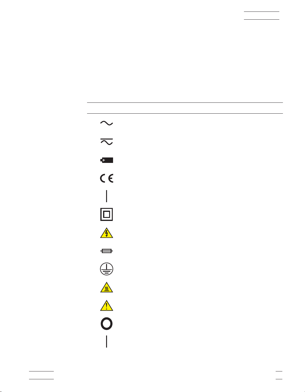
Table 1 lists the symbols used on the instrument or in this manual and the
meaning of each symbol.
Table 1 International Electrical Symbols
Symbol Description
AC (Alternating Current)
AC-DC
Battery
Complies with European Union directives
1 Before You Start
DC
Double Insulated
Electric Shock
Fuse
PE Ground
Hot Surface (Burn Hazard)
Read the User’s Manual (Important Information)
Off
On
9105/9107 1
Page 9
1 Before You Start
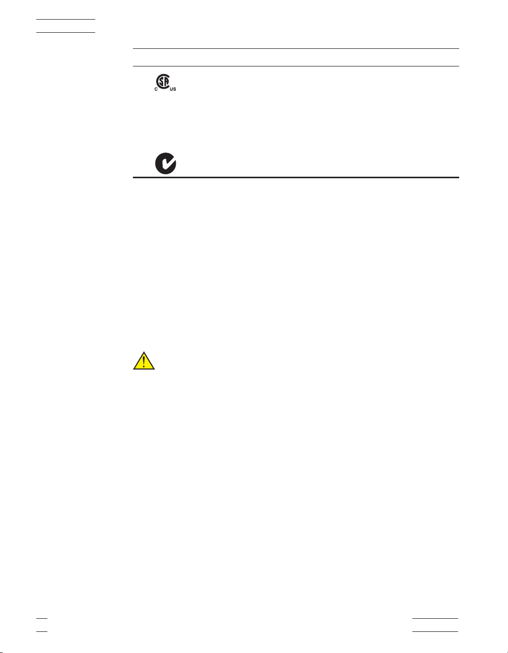
Symbol Description
Canadian Standards Association
CAT II
OVERVOLTAGE (Installation) CATEGORY II, Pollution Degree 2 per IEC1010-1 refers to the
level of Impulse Withstand Voltage protection provided. Equipment of OVERVOLTAGE CATE
GORY II is energy-consuming equipment to be supplied from the fixed installation. Exam
ples include household, office, and laboratory appliances.
C-TIC Australian EMC
1.2 Safety Information
Use the instrument only as specified in this manual. Otherwise, the protection
provided by the instrument may be impaired. Refer to the safety information
below and throughout the manual.
The following definitions apply to the terms “Warning” and “Caution”.
• “Warning” identifies conditions and actions that may pose hazards to the
user.
• “Caution” identifies conditions and actions that may damage the instrument being used.
1.2.1
Warnings
To avoid possible electric shock or personal injury, follow these guidelines.
-
-
•
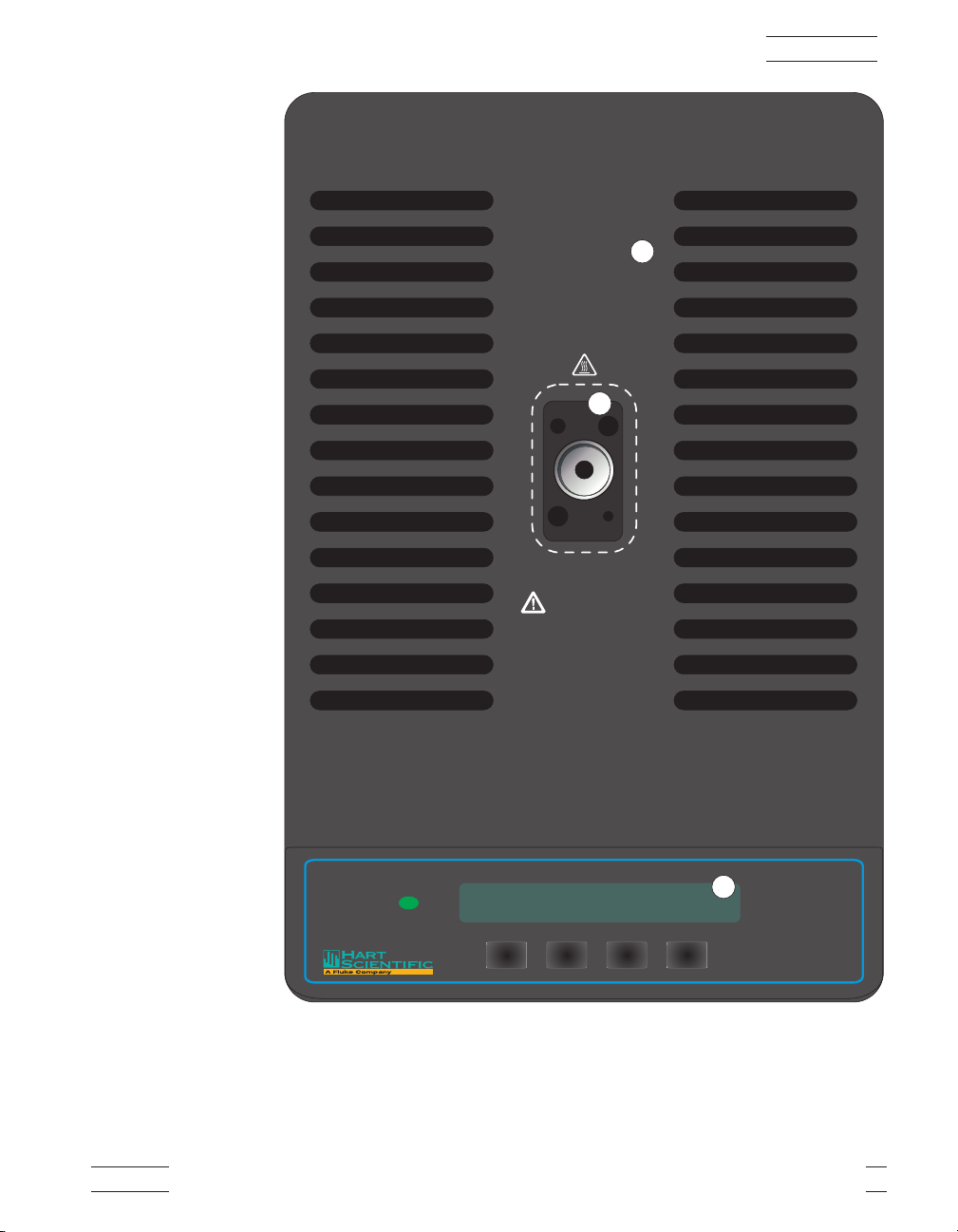
BURN HAZARD – Do Not touch the well access surface of the unit.
(Refer to Figure 1 on page 3.)
•
The temperature of the well access (1) will be the same as the actual tem
perature shown on the display (2), e.g. if the unit is set at 600°C and the
display reads 600°C, the well is at 600°C.
•
The top sheet metal (3) of the dry-well may exhibit extreme temperatures
for areas close to the well access.
•
The air over the well can reach temperatures greater than 200°C.
PROBES SHOULD ONLY BE INSERTED AND REMOVED FROM
THE UNIT WHEN THE UNIT IS SET AT TEMPERATURES LESS
THAN 200°C.
•
DO NOT TURN OFF THE UNIT AT TEMPERATURES HIGHER
THAN 100°C. This could create a hazardous situation. Select a set-point
less than 100°C and allow the unit to cool before turning it off.
2 Hart Scientific
-
Page 10
1
WARNING:
THIS AREA IS HOT
1 Before You Start
3
2
Set Down Up Exit
9105
Figure 1 Top View
9105/9107 3
Page 11

1 Before You Start
DO NOT REMOVE INSERTS AT HIGH TEMPERATURES. Inserts
•
will be the same temperature as the display temperature. Use extreme care
when removing hot inserts.
DO NOT operate this unit without a properly grounded, properly polar
•
ized power cord.
DO NOT connect this unit to a non-grounded, non-polarized outlet.
•
HIGH VOLTAGE is used in the operation of this equipment. SEVERE
•
INJURY OR DEATH may result if personnel fail to observe safety pre
cautions. Before working inside the equipment, turn power off and dis
connect power cord.
Always replace the fuse with one of the same rating, voltage, and type.
•
Overhead clearance is required. DO NOT place unit under a cabinet or
•
other structure.
DO NOT use this unit for any application other than calibration work.
•
• DO NOT use this unit in environments other than those listed in the
user’s manual.
• DO NOT turn the unit upside down with the inserts in place; the inserts
will fall out of the unit.
-
-
-
• DO NOT operate near flammable materials.
• Use of this instrument at HIGH TEMPERATURES for extended periods
of time requires caution.
•
Completely unattended high temperature operation is not recom
mended for safety reasons.
•
Before initial use, after transport and anytime the dry-well has not been
energized for more than 10 days, the calibrator must be energized for a
dry-out period of 1 to 2 hours before it can be assumed to meet all of the
safety requirements of the IEC1010-1.
•
Follow all safety guidelines listed in the user’s manual.
•
CALIBRATION EQUIPMENT should only be used by TRAINED PER
SONNEL.
-
1.2.2
Cautions
To avoid possible damage to the instrument, follow these guidelines.
•
Components and heater lifetime can be shortened by continuous high
temperature operation.
4 Hart Scientific
-
Page 12

Components and heater lifetime can be shortened by continuous high
•
temperature operation.
Most probes have handle temperature limits. Be sure that the probe handle
•
temperature limit is not exceeded in the air above the unit.
(9107 only) Always use the well insulator, see Section 5.4.
•
Allow for test probe expansion inside the well as the dry-well heats.
•
DO NOT use fluids to clean out the well.
•
Never introduce any foreign material into the probe hole of the insert.
•
Fluids, etc. can leak into the calibrator causing damage.
DO NOT change the values of the calibration constants from the factory
•
set values. The correct setting of these parameters is important to the
safety and proper operation of the calibrator.
DO NOT slam the probe stems in to the well. This type of action can
•
cause a shock to the sensor and affect the calibration.
• DO use a ground fault interrupt device.
1.3 Hart Scientific Authorized Service Centers
1 Before You Start
Please contact one of the following authorized Service Centers to coordinate
service on your Hart product:
Hart Scientific, Inc.
799 E. Utah Valley Drive
American Fork, UT 84003-9775
USA
Phone: +1.801.763.1600
Telefax: +1.801.763.1010
E-mail: support@hartscientific.com
Fluke Nederland B.V.
Customer Support Services
Science Park Eindhoven 5108
5692 EC Son
NETHERLANDS
Phone: +31-402-675300
9105/9107 5
Page 13

1 Before You Start
Telefax: +31-402-675321
E-mail: ServiceDesk@fluke.nl
Fluke Int'l Corporation
Service Center - Instrimpex
Room 2301 Sciteck Tower
22 Jianguomenwai Dajie
Chao Yang District
Beijing 100004, PRC
CHINA
Phone: +86-10-6-512-3436
Telefax: +86-10-6-512-3437
E-mail: xingye.han@fluke.com.cn
Fluke South East Asia Pte Ltd.
Fluke ASEAN Regional Office
Service Center
83 Clemenceau Avenue
#15-15/06 Ue Square
239920
SINGAPORE
Phone: +65-737-2922
Telefax: +65-737-5155
E-mail: antng@singa.fluke.com
When contacting these Service Centers for support, please have the following
information available:
•
Model Number
•
Serial Number
•
Voltage
•
Complete description of the problem
6 Hart Scientific
Page 14

2 Introduction
2 Introduction
The Hart Scientific Model 9105/9107 dry-well calibrator may be used as a por
table instrument for calibration of temperature probes. The 9105 operates over
the range of –25°C and 140°C. The 9107 operates over the range of –45°C to
140°C.
These dry-well calibrators feature an interchangeable aluminum probe sleeve
along with 4 fixed wells. The temperature is accurately controlled by Hart's
precision temperature controller.
The calibrator controller uses a precision platinum RTD as a sensor and con
trols the well temperature with thermoelectric modules. The LED front panel
display continuously shows the current well temperature. The temperature may
be easily set with the control buttons to any desired temperature within the
specified range.
The 9105/9107 dry-well calibrator was designed for portability, moderate cost,
and ease of operation. With proper use the instrument should provide continued
accurate calibration of temperature sensors and devices. The user should be familiar with the safety guidelines and operating procedures of the calibrator as
described in the User’s Guide.
-
-
9105/9107 7
Page 15
3 Specifications and Environmental Conditions
3 Specifications and Environmental Conditions
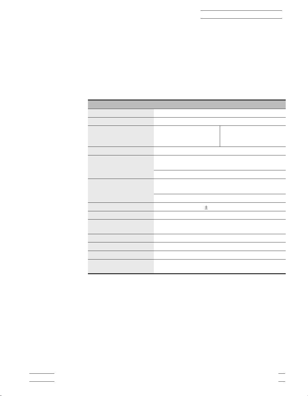
3.1 Specifications
The following table lists the specifications for this instrument. Accuracy speci
fications are applicable for a one-year calibration interval. In line with normal
prudent metrology practices, Hart Scientific recommends a short-cycle interval
of six months for new units during the first year.
9105 9107
Power
Ambient Temperature
Operating Range
Resolution
Accuracy:
Drilled Wells
Center Well
Uniformity:
Drilled Wells
Center Well
Control Stability
Controller
Test Wells
Size
Weight
Safety
Fuse Rating
115 VAC (±10%), 50/60 Hz, 230 VAC (±10%), 350 watts
5–50°C (40–120°F)
–25°C to 140°C
(–32°C to 284°F)
at 25°C (77°F)
0.01°C or 0.01°F
±0.2°C (0.36°F)
±0.1°C (0.18°F) with 6.35 mm (1/4”)probe
±0.05°C (0.09°F)
±0.2°C (0.36°F) with 6.35 (1/4”) mm probe
0.02°C (0.04°F)
Hybrid analog/digital controller with data retention
One 3/4" dia. x 6" deep, two 1/4" dia. x 6", one 3/16" dia. x 6" deep, and
one 1/8" x 6" deep
12.5"Hx8"Wx10.5" D
30 lb. including well sleeve
OVERVOLTAGE (Installation) CATEGORY II, Pollution Degree 2 per IEC1010-1
115 V: 4 A (slow blow) 250 V
230 V: 3.15 A (slow blow) 250 V
–45°C to 140°C
(–49°F to 285°F)
at 25°C (77°F)
-
3.2 Environmental Conditions
Although these instruments have been designed for optimum durability and
trouble-free operation, they must be handled with care. The instrument should
not be operated in an excessively dusty or dirty environment. Maintenance and
cleaning recommendations can be found in the Maintenance Section of this
manual.
The instrument operates safely under the following conditions:
9105/9107 9
Page 16

3 Specifications and Environmental Conditions
temperature range 5 - 50°C (41 - 122°F)
•
ambient relative humidity 15 - 50%
•
pressure - 75kPa - 106kPa
•
mains voltage within ± 10% of nominal
•
vibrations in the calibration environment should be minimized
•
altitude less than 2,000 meters
•
3.3 Warranty
Hart Scientific, Inc. (Hart) warrants this product to be free from defects in ma
terial and workmanship under normal use and service for a period as stated in
our current product catalog from the date of shipment. This warranty extends
only to the original purchaser and shall not apply to any product which, in
Hart’s sole opinion, has been subject to misuse, alteration, abuse or abnormal
conditions of operation or handling.
Software is warranted to operate in accordance with its programmed instructions on appropriate Hart products. It is not warranted to be error free.
Hart’s obligation under this warranty is limited to repair or replacement of a
product which is returned to Hart within the warranty period and is determined,
upon examination by Hart, to be defective. If Hart determines that the defect or
malfunction has been caused by misuse, alteration, abuse or abnormal conditions or operation or handling, Hart will repair the product and bill the purchaser for the reasonable cost of repair.
To exercise this warranty, the purchaser must forward the product after calling
or writing Hart for authorization. Hart assumes NO risk for in-transit damage.
For service or assistance, please contact a Hart Scientific Authorized Customer
Service Center (see Section 1.3).
THE FOREGOING WARRANTY IS PURCHASER’S SOLE AND EXCLU
SIVE REMEDY AND IS IN LIEU OF ALL OTHER WARRANTIES, EX
PRESS OR IMPLIED, INCLUDING BUT NOT LIMITED TO ANY
IMPLIED WARRANTY OR MERCHANTABILITY, OR FITNESS FOR ANY
PARTICULAR PURPOSE OR USE. HART SHALL NOT BE LIABLE FOR
ANY SPECIAL, INDIRECT, INCIDENTAL, OR CONSEQUENTIAL DAM
AGES OR LOSS WHETHER IN CONTRACT, TORT, OR OTHERWISE.
-
-
-
-
10 Hart Scientific
Page 17

4 Safety Guidelines
Operate the instrument in room temperatures between 5–50°C
•
(41–122°F). Allow sufficient air circulation by leaving at least 6 inches of
space between the instrument and nearby objects. DO NOT place under a
cabinet or other structure. Allow for overhead clearance.
The dry-well is a precision instrument. Although it has been designed for
•
optimum durability and trouble free operation, it must be handled with
care. Always carry the unit in an upright position to prevent the probe
sleeves from dropping out. The convenient fold-up handle allows one
hand carrying. The instrument should not be operated in excessively wet,
oily, dusty, or dirty environments. It is important to keep the well of the
instrument clean and clear of any foreign matter. DO NOT operate near
flammable materials.
DO NOT use fluids to clean out the well.
•
• The instrument can generate extreme temperatures. Precautions must be
taken to prevent personal injury or damage to objects. Probes may be extremely hot or cold when removed from the instrument. Cautiously handle
probes to prevent personal injury. Always use the special sleeve tongs that
are supplied with the calibrator to remove the sleeve. Carefully place
probes on a heat/cold resistant surface or rack until they are at room temperature. Never place any objects other than the special probe sleeves supplied with the calibrator into the well.
4 Safety Guidelines
• Use only a grounded AC mains supply of the appropriate voltage to
power the instrument. The Model 9105 dry-well requires 3 amps SB at
115 VAC (±10%), 50/60 Hz, 1.6 amps T at 230 VAC (±10%). The Model
9107 dry-well requires 4 amps SB at 115 VAC (±10%), 50/60 Hz, 3.15
amps T at 230 VAC (±10%).
•
Before initial use, after transport, and anytime the dry-well has not been
energized for more than 10 days, the instrument needs to be energized for
a “dry-out” period of 1-2 hours before it can be assumed to meet all of the
safety requirements of the IEC 1010-1.
•
The instrument is equipped with operator accessible fuses. If a fuse
blows, it may be due to a power surge or failure of a component. Replace
the fuse once. If the fuse blows a second time, it is likely caused by fail
ure of a component part. If this occurs, contact Hart Scientific Customer
Service. Always replace the fuse with one of the same rating, voltage, and
type. Never replace the fuse with one of a higher current rating.
•
If a mains supply power fluctuation occurs, immediately turn off the in
strument. Power bumps from brown-outs and black-outs could damage
9105/9107 11
-
-
Page 18

4 Safety Guidelines
the instrument. Wait until the power has stabilized before re-energizing
the instrument.
12 Hart Scientific
Page 19

5 Quick Start
5.1 Unpacking
5 Quick Start
Unpack the dry-well carefully and inspect it for any damage that may have oc
curred during shipment. If there is shipping damage, notify the carrier
immediately.
Verify that the following components are present:
9105 or 9107 Dry-well
•
2173 Insert, 1/4” Aluminum
•
Power Cord
•
Manual
•
Two Well Insulators (9107 only)
•
• Tongs (insert removal tool)
5.2 Set-up
Place the calibrator on a flat surface with at least 6 inches of free space around
the instrument. Overhead clearance is required. DO NOT place under a cabinet
or structure. Plug the power cord into a grounded mains outlet. Observe that the
nominal voltage corresponds to that indicated on the back of the calibrator.
Carefully insert the probe sleeve into the well. Probe sleeves should be of the
smallest hole diameter possible still allowing the probe to slide in and out eas
ily. Sleeves of various sizes are available for Hart Scientific. The well must be
clear of any foreign objects, dirt and grit before the sleeve is inserted. The
sleeve is inserted with the two small tong holes positioned upward.
-
-
Turn on the power to the calibrator by toggling the switch on the power entry
module. The fan should begin quietly blowing air through the instrument and
the controller display should illuminate after 3 seconds. After a brief self-test
the controller should begin normal operation. If the unit fails to operate please
check the power connection.
The display will begin to show the well temperature and the well heater will
start operating to bring the temperature of the well to the set-point temperature.
5.3 Power
Plug the dry-well power cord into a mains outlet of the proper voltage, fre
quency, and current capability. Typically this will be 115 VAC (±10%), 50/60
Hz (230 VAC ±10%, 50/60 Hz). Turn the dry-well on using the rear panel
9105/9107 13
-
Page 20

5 Quick Start
“POWER” switch. The dry-well will turn on and begin to heat to the previously
programmed temperature set-point. The front panel LED display will indicate
the actual dry-well temperature.
The 9107 is field switchable between 115 V and 230 V. Refer to Section 7.2,
Switching to 230 V Operation, for information on switching the voltage.
5.4 Setting the Temperature
Section 8.3 explains in detail how to set the temperature set-point on the cali
brator using the front panel keys. The procedure is summarized here.
1. Press “SET” twice to access the set-point value.
2. Press “UP” or “DOWN” to change the set-point value.
3. Press “SET” to program in the new set-point.
4. Press “EXIT” to return to the temperature display.
When the set-point temperature is changed the controller will switch the well
heater on or off to raise or lower the temperature. The displayed well temperature will gradually change until it reaches the set-point temperature. The well
may require 5 to 10 minutes to reach the set-point depending on the span. Another 5 to 10 minutes is required to stabilize with ±0.1°C of the set-point. Ultimate stability may take 15 to 20 minutes more of stabilization time.
-
14 Hart Scientific
Page 21

6 Parts and Controls
The user should become familiar with the dry-well calibrator and its parts.
6.1 Rear Panel
SeeFigure2.
Power Cord - At the rear of the calibrator is the removable power cord that
plugs into a standard 115 VAC grounded socket. (230 VAC optional.)
Power Switch (9105) - The power switch is located on the rear panel of the
calibrator.
DISPLAY
HOLD
RS-232
6 Parts and Controls
DISPLAY HOLD RS-232
IEEE-488 (option)
IEEE-488
POWER
115V/230V 50/60 Hz
350W
115V
POWER
115V 50/60 Hz
350W 2.5A
|
U
F
E
S
E
F
U
S
3A 250V
CAT 300V
E
S
U
F
F
U
S
E
115V 4A T 250V
230V 3.15A T 250V
Before opening disconnect mains.
Vor Öffnen des Gehäuses Netzstecker ziehen.
Avant d’ouvrir l’appereil retirez la fichemâle.
0
201811
9105
Figure 2 Rear Panel
9105/9107 15
MADE IN USA
9107
Page 22

6 Parts and Controls
6.2 Front Panel
Power Entry Module (9107) - The power switch is located on the power entry
module (PEM). The PEM also houses the fuses.The supply voltage for the unit
is indicated on the PEM.
Serial Port - This D-9 connector is for interfacing the calibrator to a computer
or terminal with serial RS-232 communications.
Display Hold - The two terminals may be used to wire a switch or cut-out to
the calibrator to trigger the instrument to freeze the displayed well temperature.
Fuse Holders - At the rear of the calibrator are two user accessable fuse
holders.
See Figure 3 on page 16.
Controller Display - The digital display is an important part of the temperature
controller because it not only displays set and actual temperatures but also vari
ous calibrator functions, settings, and constants. The display shows temperatures in units according to the selected scale °C or °F.
Controller Keypad - The four button keypad allows easy setting of the
set-point temperature. The control buttons (SET, DOWN, UP, and EXIT) are
used to set the calibrator temperature set-point, access and set other operating
parameters, and access and set calibration parameters.
-
Setting the control temperature is done directly in degrees of the current scale.
It can be set to one-hundredth of a degree Celsius.
The functions of the buttons are as follows:
SET – Used to display the next parameter in the menu and to set parameters to
the displayed value.
DOWN – Used to decrement the displayed value of parameters.
Set Down Up Exit
9105
Figure 3 Front Panel
16 Hart Scientific
Page 23

UP–Usedtoincrementthedisplayedvalue.
EXIT – Used to exit from a menu. When EXIT is pressed any changes made to
the displayed value will be ignored.
Control Indicator - The Control Indicator is a two color light emitting diode.
This indicator lets the user visually see the ratio of heating to cooling. When
the indicator is constant red the well is heating, and when it is constant green
the well is cooling. When the indicator is flashing then the temperature is being
held constant.
6.3 Constant Temperature Block Assembly
6.3.1 Constant Temperature Block
The block, Figure 4, is made of aluminum and provides a relatively constant
and accurate temperature environment in which the sensors that are to be cali
brated are inserted. The .75 inch diameter hole in the center of the block may
be used for sensors of that size or sleeved down with various sized probe
sleeves. The block also has 4 smaller holes of various sizes. Attached to the
block are Peltier thermoelectric modules which heat or cool the block to maintain a constant temperature. A high-quality platinum RTD is imbedded in the
block to sense the temperature and provide feedback to the temperature controller.
6 Parts and Controls
-
3/4" O.D. Aluminum Insert
3/16" Well
1/4" Well
Figure 4 Well and Insert
6.3.2
9105/9107 17
Probe Sleeves and Tongs
Probe sleeves of various internal hole sizes are available to allow the user's
probe to fit snugly into the well whatever the diameter of the probe.
1/4" Well
1/8" Well
Page 24

6 Parts and Controls
6.4 Well Insulator (9107only)
Standard Insert Sizes
Model Number Size
2168 Blank insert
1
2169
2170
2171
2172
2173
2174
2175
2176
2177
2178
2179
insert
¢¢
16
1
insert
¢¢
8
5
insert
¢¢
32
3
insert
¢¢
16
1
insert
¢¢
4
5
insert
¢¢
16
3
insert
¢¢
8
1
insert
¢¢
2
5
insert
¢¢
8
7
insert
¢¢
16
9
insert
¢¢
16
The 9107 includes a well insulator made of white polymer foam that fits into
the opening above the block (see Figure 5). The well insulator has three
purposes:
1. Insulate the top of the block to minimize the vertical temperature gradient in the block.
2. Insulate the top of the block to prevent excessive heat from flowing into
or out of the block which may prevent it from reaching its minimum or
maximum temperatures.
3. Shield the top of the block from open air thus reducing the potential for
excessive water condensation on the block. Excessive water on the
block can cause corrosion over a long period of time. Water condensa
-
tion that freezes expands and can damage the block.
For these reasons the 9107 must always have the well insulator installed when
it is operated with well temperatures below 25°C. The well insulator fits snugly
into the circular cavity just above the block. For best results do not push the
well insulator all the way down into the cavity. Instead, leave the top of the well
18 Hart Scientific
Page 25

6 Parts and Controls
insulator flush with the top of the cavity. The well insulator has a slot through
which a probe can be inserted.
Figure 5 Well Insulator Top View
9105/9107 19
Page 26

7 General Operation
7.1 Calibrator Set-Up
Place the calibrator on a flat surface with at least 6 inches of free space around
the instrument. Overhead clearance is required. DO NOT place under a cabinet
or other structure.Plug the power cord into a grounded mains outlet. Observe
that the nominal voltage corresponds to that indicated on the back of the
calibrator.
Gently insert the probe sleeve into the well. The probe sleeve should be of the
smallest hole size possible while allowing the probe to slide in and out easily.
Sleeves of various sizes are available from the manufacturer. The well must be
clear of any foreign objects, dirt and grit before the sleeve is inserted. The
sleeve is inserted with the two small tong holes positioned upward.
7 General Operation
Turn on the power to the calibrator by toggling the switch at the rear of the in
strument to the “l” (on) position. The fan will begin circulating air through the
instrument. After a brief self test the controller should begin normal operation
showing the well temperature. The block will heat or cool until it reaches the
programmed set-point.
7.2 Switching to 230 V Operation (9107 only)
To change the mains voltage on the 9107 perform the following steps.
1. Unplug the unit from the power source.
2. Insert a flat-headed screwdriver into the slot on the PEM.
3. Remove the fuse holder from the PEM.
4. Change the fuses to the appropriate current rating for the voltage (see
Section 4, Safety Guidelines).
5. Replace fuse holder with the appropriate voltage displayed through the
window of the PEM.
6. The power cord may need to be changed to mate with the appropriate
230 VAC or 115 VAC socket. Some options are listed.
•
230 VAC: Europe – 10A approved cord with CEE 717 plug
US – 15A approved cord with a NEMA 6-15 straight
blade plug
-
•
115 VAC: US – 15A approved cord with a NEMA 5-15 plug.
9105/9107 21
Page 27

7 General Operation
7.3 Setting the Temperature
Section 8.3 explains in detail how to set the temperature set-point on the cali
brator using the front panel keys. The procedure is summarized here.
(1) Press “SET” twice to access the set-point value.
(2) Press “UP” or “DOWN” to change the set-point value.
(3) Press “SET” to program in the new set-point.
(4) Press “EXIT” to return to the temperature display.
When the set-point temperature is changed the controller will switch the well
heater on or off to raise or lower the temperature. The cycle indicator, a two
color LED, will also indicate on (red and heating) or off (green and cooling).
The displayed well temperature will gradually change until it reaches the
set-point temperature. The well may require 5 to 20 minutes to reach the
set-point depending on the span. Another 5 to 10 minutes is required for the
temperature to stabilize.
7.4 Calibrating Probes
The dry-well block provides a constant temperature environment in which
probes may be compared. The probes inserted into the block may be compared
to the well temperature displayed on the front panel of the calibrator. The
probes should be inserted the full depth of the well since the temperature at the
bottom of the well will most closely agree with the displayed temperature.
For greater accuracy the probes may be compared to a reference thermometer
inserted into the block. The reference thermometer may be inserted into one
hole while the probes to be calibrated are inserted into another. The drawback
to this method is that because of temperature variations throughout the block
there may be a small temperature difference between one hole and another
which can cause errors.
-
Using the same hole for the reference thermometer and the test probe may have
better results. This however requires switching the probes which takes more
time. One must allow a few minutes after inserting the probes for the tempera
ture to stabilize before making measurements. Because of temperature varia
tions along the length of the well, best results are obtained when comparing
probes of similar construction and inserting them the same depth into the well.
22 Hart Scientific
-
-
Page 28

8 Controller Operation
8 Controller Operation
This chapter discusses in detail how to operate the dry-well temperature con
troller using the front control panel. Using the front panel key-switches and
LED display the user may monitor the well temperature, set the temperature
set-point in degrees C or F, monitor the heater output power, adjust the control
ler proportional band, set the cut-out set-point, and program the probe calibra
tion parameters, operating parameters, serial and IEEE-488 interface
configuration, and controller calibration parameters. Operation of the functions
are summarized in Figure 6 on page 24.
In the following discussion a solid box around the word SET, UP, EXIT or
DOWN indicates the panel button while the dotted box indicates the display
reading. Explanation of the button or display reading are to the right of each
button or display value.
8.1 Well Temperature
The digital LED display on the front panel allows direct viewing of the actual
well temperature. This temperature value is what is normally shown on the display. The units, C or F, of the temperature value are displayed at the right. For
example,
20.00 C
The temperature display function may be accessed from other functions by
pressing the “EXIT” button.
-
-
-
Well temperature in degrees Celsius
8.2 Reset Cut-out
If the over-temperature cut-out has been triggered then the temperature display
will alternately flash,
cut-out
The message will continue to flash until the temperature is reduced and the
cut-out is reset.
The cut-out has two modes — automatic reset and manual reset. (See Section
8.11.2.2) The mode determines how the cut-out is reset which allows the instru
ment to heat up again. When in automatic mode, the cut-out will reset itself as
soon as the temperature is lowered below the cut-out set-point. With manual re
set mode the cut-out must be reset by the operator after the temperature falls
below the set-point.
9105/9107 23
Indicates cut-out condition
-
-
Page 29

8 Controller Operation
EXIT
EXIT
EXIT
EXIT
EXIT
EXIT
EXIT
EXIT
EXIT
Cutout Active
Cutout Active
Display
Temperature
SET
Reset Cutout
Reset Cutout
SET
SET
Select Setpoint
SET
Adjust Setpoint
SET
Adjust Units
SET
Scan On/Off
SET
Scan Rate
SET
Display Hold Mode
SET
Scan Hold
SET
SET
SECONDARY FUNCTIONS
SET
EXIT
EXIT
EXIT
EXIT
Set Proportional Band
+
UP
+
EXIT
Display Power
SET
SET
Set Cutout Temp.
SET
Configuration Menu
SET
EXIT
SET
SET/EXIT
Program Menu
SET
Number of Setpoints
SET
Select SetpointSelect Setpoint
EXIT
Soak Time
SET
Program Function Mode
EXIT
Program Control
Probe
Menu
SET
R0
SET
EXIT
Adj. R0
SET/EXIT
ALPHA
SET
EXIT
Adj. ALPHA
SET/EXIT
DELTA
EXIT
SET
Adj. DELTA
SET/EXIT
BETA
EXIT
SET
Adj. BETA
SET/EXIT
Figure 6 Controller Function Flowchart
DOWN
EXITEXITEXIT EXIT EXIT
UP
Operating
Parameters
Menu
SET SET SET SET
Units
SET
Adjust
Units
SET/EXIT
Cutout
Reset Mode
SET
Adj. Cutout
Reset Mode
SET/EXIT
Stability
SET
Adjust
Stability
SET/EXIT
UP UP UP
DOWN DOWN DOWN
EXIT
Serial
Interface
Menu
BAUD
Rate
SET SET
EXITEXIT EXIT
Adjust
BAUD Rate
SET/EXIT
Sample
Period
EXITEXIT
SET
Adj. Sample
Period
SET/EXIT
Duplex
Mode
SET
EXIT
Adj. Duplex
Mode
SET/EXIT
Linefeed
SET
EXIT
Adjust
Linefeed
SET/EXIT
IEEE-488
Interface
Menu
Device
Address
SET
Adj. Device
Address
SET/EXIT
Option Installed
IEEE-488
Calibration
Calibration
Menu
Menu
SET
X5
X5
CTO
CTO
EXIT
SET
Adjust CTO
Adjust CTO
SET/EXIT
SET/EXIT
SET
SET
Adjust B0
Adjust B0
SET/EXIT
SET/EXIT
SET
SET
DO NOT CHANGE THESE VALUES. SEE MANUAL
Adjust BG
Adjust BG
SET/EXIT
SET/EXIT
SET/EXIT
SET/EXIT
SET
SET
Adjust SCO
Adjust SCO
SET/EXIT
SET/EXIT
EXIT
B0
B0
EXIT
EXIT
BG
BG
EXIT
EXIT
SCO
SCO
EXIT
EXIT
24 Hart Scientific
Page 30

8 Controller Operation
When the cut-out is active and the cut-out mode is set to manual (“reset”) then
the display will flash “cut-out” until the user resets the cut-out. To access the
reset cut-out function press the “SET” button.
S
The display will indicate the reset function.
rESEt ?
Press “SET” once more to reset the cut-out.
S
This will also switch the display to the set temperature function. To return to
displaying the temperature press the “EXIT” button. If the cut-out is still in the
over-temperature fault condition the display will continue to flash “cut-out”.
The well temperature must drop a few degrees below the cut-out set-point be
fore the cut-out can be reset.
Access cut-out reset function
Cut-out reset function
Reset cut-out
8.3 Temperature Set-point
The temperature set-point can be set to any value within the range and with resolution as given in the specifications. Be careful not to exceed the safe upper
temperature limit of any device inserted into the well. The safety cut-out should
be properly adjusted to help prevent this occurrence.
Setting the temperature involves two steps: (1) select the set-point memory and
(2) adjust the set-point value.
-
8.3.1 Programmable Set-points
The controller stores 8 set-point temperatures in memory. The set-points can be
quickly recalled to conveniently set the calibrator to a previously programmed
temperature set-point.
To set the temperature one must first select the set-point memory. This function
is accessed from the temperature display function by pressing “SET”. The
number of the set-point memory currently being used is shown at the left on the
display followed by the current set-point value.
20.00 C
S
Access set-point memory
1. 20.0
9105/9107 25
Well temperature in degrees Celsius
Set-point memory 1, 20.0°C currently used
Page 31

8 Controller Operation
To change the set-point memory press “UP” or “DOWN”.
3. -10.0
Press “SET” to accept the new selection and access the set-point value.
S
Accept selected set-point memory
8.3.2 Set-point Value
The set-point value may be adjusted after selecting the set-point memory and
pressing “SET”. The set-point value is displayed with the units, C or F, at the
left.
C -10.00
If the set-point value need not be changed then press “EXIT” to resume dis
playing the well temperature. Press “UP” or “DOWN” to adjust the set-point
value.
C -12.00
When the desired set-point value is reached press “SET” to accept the new
value and access the temperature scale units selection. If “EXIT” is pressed instead then any changes made to the set-point will be ignored.
New set-point memory 3, –10.0°C
Set-point 3 value in °C
-
New set-point value
S
Accept new set-point value
8.3.3 Temperature Scale Units
The temperature scale units of the controller maybe set by the user to degrees
Celsius (°C) or Fahrenheit (°F). The units are used in displaying the well tem
perature, set-point, and proportional band.
Press “SET” after adjusting the set-point value to change display units.
Un= C Scale units currently selected
Press “UP” or “DOWN” to change the units.
Un= F New units selected
8.4 Scan
The scan rate can be set and enabled so that when the set-point is changed the
dry-well will heat or cool at a specified rate (degrees per minute) until it
26 Hart Scientific
-
Page 32

reaches the new set-point. With the scan disabled the dry-well will heat or cool
at the maximum possible rate.
8.4.1 Scan Control
The scan is controlled with the scan on/off function that appears in the main
menu after the set-point function.
ScAn=OFF Scan function off
Press “UP” or “DOWN” to toggle the scan on or off.
ScAn=On Scan function on
Press “SET” to accept the present setting and continue.
8 Controller Operation
S
Accept scan setting
8.4.2 Scan Rate
The next function in the main menu is the scan rate. The scan rate can be set
from .1 to 100 °C/min. The maximum scan rate however is actually limited by
the natural heating or cooling rate of the instrument. This is often less than 100
°C/min, especially when cooling.
The scan rate function appears in the main menu after the scan control function.
The scan rate units are in degrees per minute, degrees C or F depending on the
selected units.
Sr= 10.0
Press“UP”or“DOWN”tochangethescanrate.
Sr= 2.0
Press “SET” to accept the new scan rate and continue.
S
Accept scan rate
Scan rate in °C/min
New scan rate
8.5 Temperature Display Hold
The instrument has a display hold function which allows action of an external
switch to freeze the displayed temperature and stop the set-point from scan
ning. This is useful for testing thermal switches and cut-outs. This section ex
plains the functions available for operating the temperature hold feature. An
example follows showing how to set up and use the hold feature to test a
switch.
9105/9107 27
-
-
Page 33

8 Controller Operation
8.5.1 Hold Temperature Display
When the hold feature is enabled you can easily switch the display between the
normal temperature display and the hold temperature display by simply press
ing the “UP” or “DOWN” buttons. The hold temperature display shows the
hold temperature on the right and the switch status on the left. For the status
“c” means the switch is closed and “o” means the switch is open. The status
flashes when the switch is in its active position (opposite the normal position).
The hold temperature shows what the temperature of the well was when the
switch changed from its normal position to its active position. While the switch
is in the normal position the hold temperature will follow the well temperature.
Operation of the hold temperature display is outlined below.
-
43.56 C
U
Access hold display
c 44.8C
Note that the hold function display is not accessible if the function mode is set
to “OFF”. (See Section 8.5.2)
To return to the normal well temperature display press “DOWN” or “EXIT”.
8.5.2 Mode Setting
The temperature hold feature has three modes of operation. In the normally-closed (n.c.) mode the hold temperature display freezes when the switch
opens. In the normally-open (n.o.) mode the hold temperature display freezes
when the switch closes. Whenever the switch is in the normal position the hold
temperature follows the well temperature.
There is also an automatic mode. In this mode the normal position is set to
whatever the switch position is when the set-point is changed. For example, if
the switch is currently open when the set-point is changed, the closed position
then becomes the new active position. The normal position will be set automati
cally under any of the following conditions, (1) a new set-point number is se
lected, (2) the set-point value is changed, (3) a new set-point is set through the
communications channels, or (4) the ramp-and-soak program is running and
automatically steps to the next set-point in the sequence. The automatic mode is
useful for repetitive tests of the opening and closing temperatures of a switch.
Well temperature display
Switch status and hold temperature
-
-
The temperature hold feature can also be disabled by setting the mode to
“OFF”.
The operating mode of the temperature hold is set in the primary menu after the
scan rate setting.
28 Hart Scientific
Page 34

HoLd=OFF Hold mode set to off
To change the mode press “UP” or “DOWN”.
HoLd=Aut Automatic mode
HoLd=n.c. Normally closed mode
HoLd=n.o. Normally open mode
Press “SET” to accept the displayed setting.
8.5.3 Scan Hold
8 Controller Operation
In addition to controlling the hold temperature display, a switch can also con
trol set-point scanning by enabling the scan hold function. When the switch
changes from its normal position to its active position scanning will stop. For
the scan hold to be effective scanning must be enabled and the scan rate should
be set to a relatively low value (see sections 8.4.1 and 8.4.2).
The scan hold is set in the primary menu after the temperature hold mode
setting.
SHoLd=OF Scan hold set to off
To change the mode press “UP” or “DOWN”.
SHoLd=On Scan hold set to on
Press “SET” to accept the displayed setting.
8.5.4 Switch Wiring
The thermal switch or cut-out is wired to the calibrator at the two terminals at
the back of the dry-well calibrator labeled “DISPLAY HOLD”. The switch
wires may be connected to the terminals either way. Internally the black termi
nal connects to ground. The red terminal connects to +5V through a 10 kΩ re
sistor. The calibrator measures the voltage at the red terminal and interprets
+5V as open and 0V as closed.
-
-
-
8.5.5 Switch Test Example
This section describes a possible application for the temperature hold feature
and how the instrument is set up and operated.
Suppose you have a thermal switch which is supposed to open at about 75°C
and close at about 50°C and you want to test the switch to see how accurate and
repeatable it is. You can use the temperature hold feature and the ramp and
9105/9107 29
Page 35

8 Controller Operation
soak feature (described in detail in the next section) to test the switch. Measure
ments can be made by observing the display or, preferably, by collecting data
using a printer or computer connected to the RS-232 port. To set up the test do
the following steps.
1. Connect the switch wires to the terminals on the back of the dry-well and
place the switch in the well.
2. Enable set-point scanning by setting the scan to “ON” in the primary menu
(see Section 8.4.1).
3. Set the scan rate to a low value, say 1.0°C/min. (see Section 8.4.2). If the
scan rate is too high you may lose accuracy because of transient temperature
gradients. If the scan rate is too low the duration of the test may be longer than
is necessary. You may need to experiment to find the best scan rate.
4. Set the hold mode to automatic (see Section 8.5.2).
5. Set the scan hold to “ON” (see Section 8.5.3).
6. Set the number of program set-points to 2 in the program menu (see Section
8.6.1).
7. Set the first program set-point to a value below the expected lower switch
temperature, say 40°C, in the program menu (see Section 8.6.2).
8. Set the second program set-point to a value above the expected upper switch
temperature, say 90°C.
-
9. Set the program soak time to allow enough time to collect a number of data
points, say 2 minutes (see Section 8.6.3).
10. Set the program function to mode 4 so that the instrument will cycle between the 2 set-points repeatedly. (See Section 8.6.4.)
11. Start the program (see Section 8.6.5).
12. Collect data on a computer connected to the RS-232 port. Refer to Section
9 for instructions on configuring the RS-232 communications interface. The
data may appear as shown in Figure 7. The maxima and minima are the switch
temperatures.
30 Hart Scientific
Page 36

90
85
80
75
70
65
Deg C
60
55
50
45
40
Figure 7 Switch Test Data
8.6 Ramp and Soak Program Menu
8 Controller Operation
Time
The ramp and soak program feature allows the user to program a number of
set-points and have the dry-well automatically cycle between the temperatures,
holding at each for a determined length of time. The user can select one of four
different cycle functions.
The program parameter menu is accessed by pressing “SET” and then “UP”.
20.00 C
S+U
ProG
Press “SET” to enter the program menu
S
Enter program menu
Well temperature
Access program menu
Program menu
8.6.1 Number of Program Set-points
The first parameter in the program menu is the number of set-points to cycle
through. Up to 8 set-points can be used in a ramp and soak program.
Pn=8
Number of program set-points
9105/9107 31
Page 37

8 Controller Operation
Use the “UP” or “DOWN” buttons to change the number from 2 to 8.
Pn=3
Press “SET” to continue. Pressing “EXIT” will cause any changes made to the
parameter to be ignored.
S
8.6.2 Set-points
The next parameters are the program set-points.
1 25.0
Use the “UP” or “DOWN” buttons to select any of the set-points.
3 10.0
Press “SET” to change the set-point.
C 10.00
Use “UP” and “DOWN” to change the set-point value.
C 13.50
Press “SET” to save the new set-point value.
New number of program set-points
Save new setting
First set-point
Third set-point
Set-point value
New set-point value
The other set-points can also be set in the same manner. Once the set-points are
programmed as desired press “EXIT” to continue.
E
Continue to next menu function
8.6.3 Program Soak Time
The next parameter in the program menu is the soak time. This is the time, in
minutes, for which each of the program set-points will be maintained after set
tling before proceeding to the next set-point. The duration is counted from the
time the temperature settles to within a specified stability. The stability require
ment can be set in the parameter menu as explained in Section 8.11.2.3. The
default is 0.1°C.
Pt=15
Use the “UP” or “DOWN” buttons to change the time.
Pt=5
32 Hart Scientific
Soak time in minutes
New soak time
-
-
Page 38

Press “SET” to continue.
8 Controller Operation
S
Save new setting
8.6.4 Program Function Mode
The next parameter is the program function or cycle mode. There are four pos
sible modes which determine whether the program will scan up (from set-point
1 to n) only or both up and down (from set-point n to 1), and also whether the
program will stop after one cycle or repeat the cycle indefinitely. The table be
low shows the action of each of the four program mode settings.
Function Action
1up-stop
2 up-down-stop
3 up-repeat
4 up-down-repeat
Pf=1
Use the “UP” or “DOWN” buttons to change the mode.
Pf=4
Press “SET” to continue.
Program mode
New mode
-
-
S
Save new setting
8.6.5 Program Control
The final parameter in the program menu is the control parameter. You may
choose between three options to either start the program from the beginning,
continue the program from where it was when it was stopped, or stop the
program.
Pr=OFF
Use the “UP” or “DOWN” buttons to change the status.
Pr=StArt
Press “SET” to activate the new program control command and return to the
temperature display.
9105/9107 33
Program presently off
Start cycle from beginning
Page 39

8 Controller Operation
S
Activate new command.
8.7 Secondary Menu
Functions which are used less often are accessed within the secondary menu.
The secondary menu is accessed by pressing “SET” and “EXIT” simulta
neously and then releasing. The first function in the secondary menu is the
heater power display.
8.8 Heating Power
The temperature controller controls the temperature of the well by heating or
cooling the well with the thermoelectric modules. The amount of heating or
cooling power depends on the temperature set-point of the well. This heating
(or cooling) power value may be estimated by watching the red/green control
indicator light or read directly from the digital display. By knowing the amount
of heating the user can tell if the calibrator is heating up to the set-point, cooling down, or controlling at a constant temperature. Monitoring the percent
heater power will let the user know how stable the well temperature is. With
good control stability the percent heating power should not fluctuate more than
±1% within one minute.
The heater power display is accessed in the secondary menu. Press “SET” and
“EXIT” simultaneously and release. The heater power will be displayed as a
percentage of full power.
-
20.00 C
S+E
-12 Pct
Negative numbers indicate the well is being cooled. -100% means the well is
being cooled at maximum power. 0 means the well requires neither heating nor
cooling. 100% means the well is being heated at maximum power.
To exit out of the secondary menu press “EXIT”. To continue on to the propor
tional band setting function press “SET”.
Well temperature
Access heater power in secondary menu
Heater power in percent
8.9 Proportional Band
In a proportional controller such as this, the heater output power is proportional
to the well temperature over a limited range of temperatures around the
set-point. This range of temperature is called the proportional band. At the bot
tom of the proportional band the heating is 100%. At the top of the proportional
34 Hart Scientific
-
-
Page 40

8 Controller Operation
band the cooling is 100%. Thus as the temperature rises the heater power is re
duced, which consequently tends to lower the temperature back down. In this
way the temperature is maintained at a fairly constant temperature.
The temperature stability of the well and response time depend on the width of
the proportional band. See Figure 8 on page 35. If the band is too wide the well
temperature will deviate excessively from the set-point due to varying external
conditions. This is because the power output changes very little with tempera
ture and the controller cannot respond very well to changing conditions or
noise in the system. If the proportional band is too narrow the temperature may
swing back and forth because the controller overreacts to temperature varia
tions. For best control stability the proportional band must be set for the opti
mum width.
Proportional Band too Narrow Proportional Band too Wide
Optimum Proportional Band
-
-
-
-
Figure 8 Well temperature fluctuation at various proportional band settings
The proportional band width is set at the factory to about 2.0°C. The propor
tional band width may be altered by the user if he desires to optimize the con
trol characteristics for a particular application.
The proportional band width is easily adjusted from the front panel. The width
may be set to discrete values in degrees C or F depending on the selected units.
The proportional band adjustment is accessed within the secondary menu.
Press “SET” and “EXIT” to enter the secondary menu and show the heater
power. Then press “SET” to access the proportional band.
S+E
-12 Pct
S
9105/9107 35
Access heater power in secondary menu
Heater power in percent
Access proportional band
-
-
Page 41

8 Controller Operation
Pb= 2.01C
To change the proportional band press “UP” or “DOWN”.
Pb=3.50C
To accept the new setting and access the cut-out set-point press “SET”.
Pressing “EXIT” will exit the secondary menu ignoring any changes just made
to the proportional band value.
S
8.10 Cut-out
As a protection against software or hardware fault or user error, the calibrator is
equipped with an adjustable cut-out device that will shut off power to the heater
if the well temperature exceeds a set value. This protects the instrument and
probes from excessive temperatures. The cut-out temperature is programmable
by the operator from the front panel of the controller.
If the cut-out is activated because of excessive well temperature then power to
the heater will be shut off and the instrument will cool. The well will cool until
it reaches a few degrees below the cut-out set-point temperature. At this point
the action of the cut-out is determined by the setting of the cut-out mode parameter. The cut-out has two modes — automatic reset or manual reset. If the
mode is set to automatic, then the cut-out will automatically reset itself when
the temperature falls below the reset temperature allowing the well to heat up
again. If the mode is set to manual, then the heater will remain disabled until
the user manually resets the cut-out.
Proportional band setting
New proportional band setting
Accept the new proportional band setting
The cut-out set-point may be accessed within the secondary menu. Press “SET”
and “EXIT” to enter the secondary menu and show the heater power. Then
press “SET” twice to access the cut-out set-point.
S+E
-12 Pct
S
Pb= 2.01C
S
36 Hart Scientific
Access heater power in secondary menu
Heater power in percent
Access proportional band
Proportional band setting
Access cut-out set-point
Page 42

8 Controller Operation
CO= 80C
To change the cut-out set-point press “UP” or “DOWN”.
CO= 70C
To accept the new cut-out set-point press “SET”.
S
The next function is the configuration menu. Press “EXIT” to resume display
ing the well temperature.
Accept cut-out set-point
Cut-out set-point
New cut-out set-point
8.11 Controller Configuration
The controller has a number of configuration and operating options and calibra
tion parameters that are programmable via the front panel. These are accessed
from the secondary menu after the cut-out set-point function by pressing
“SET”. There are 5 sets of configuration parameters—probe parameters, oper-
ating parameters, serial interface parameters, IEEE-488 interface parameters,
and controller calibration parameters. The menus are selected using the “UP”
and “DOWN” keys and then pressing “SET”.
8.11.1 Probe Parameters
-
-
The probe parameter menu is indicated by,
PrObE
Press “SET” to enter the menu. The probe parameters menu contains the pa
rameters, R
tance-temperature relationship of the platinum control probe. These parameters
may be adjusted to improve the accuracy of the calibrator. This procedure is ex
plained in detail in Section 10.
The probe parameters are accessed by pressing “SET” after the name of the
parameter is displayed. The value of the parameter may be changed using the
“UP” and “DOWN” buttons. After the desired value is reached press “SET” to
set the parameter to the new value. Pressing “EXIT” will cause the parameter to
be skipped ignoring any changes that may have been made.
8.11.1.1 R
9105/9107 37
0
This probe parameter refers to the resistance of the control probe at 0°C. The
value of this parameter is set at the factory for best instrument accuracy.
and ALPHA, DELTA, and BETA which characterize the resis
0
Probe parameters menu
-
-
-
Page 43

8 Controller Operation
8.11.1.2 ALPHA
8.11.1.3 DELTA
8.11.1.4 BETA
8.11.2 Operating Parameters
This probe parameter refers to the average sensitivity of the probe between 0
and 100°C. The value of this parameter is set at the factory for best instrument
accuracy.
This parameter relates to the second order nonlinearity of the sensor. The value
is set at the factory for best instrument accuracy.
This parameter relates to the higher order nonlinearity of the sensor below 0°C.
The value is set at the factory for best instrument accuracy.
The operating parameters menu is indicated by,
PAr
Press “UP” to enter the menu. The operating parameters menu contains the
units scale selection set and cut-out reset mode setting.
Operating parameters menu
8.11.2.1 Temperature Scale Units
The temperature scale units of the controller may be set by the user to degrees
Celsius (°C) or Fahrenheit (°F). The units will be used in displaying the well
temperature, set-point, proportional band, and cut-out set-point.
The temperature scale units selection is the first function in the operating pa
rameters menu.
Un= C
Press “UP” or “DOWN” to change the units.
Un= F
Press “SET” to accept the new selection and resume displaying the well
temperature.
Scale units currently selected
New units selected
8.11.2.2 Cut-out Reset Mode
The cut-out reset mode determines whether the cut-out resets automatically
when the well temperature drops to a safe value or must be manually reset by
the operator.
-
38 Hart Scientific
Page 44

The parameter is indicated by,
8 Controller Operation
CtorSt
Press “SET” to access the parameter setting. Normally the cut-out is set for au
tomatic mode.
Cto=Auto
To change to manual reset mode press “UP” and then “SET”.
Cto=rSt
Cut-out reset mode parameter
Cut-out set for automatic reset
Cut-out set for manual reset
8.11.2.3 Soak Stability
The soak stability controls the required stability of the well temperature for the
soak time (Section 8.6.3). The stability is in degrees Celsius. The default is
0.1°C. This value can be changed in the parameter menu.
8.11.3 Serial Interface Parameters
The serial RS-232 interface parameters menu is indicated by,
SErIAL
The serial interface parameters menu contains parameters which determine the
operation of the serial interface. These controls only apply to instruments fitted
with the serial interface. The parameters in the menu are — BAUD rate, sample
period, duplex mode, and linefeed.
Serial RS-232 interface parameters menu
-
8.11.3.1 BAUD Rate
The BAUD rate is the first parameter in the menu. The BAUD rate setting de
termines the serial communications transmission rate.
The BAUD rate parameter is indicated by,
BAUd
Press “SET” to choose to set the BAUD rate. The current BAUD rate value will
then be displayed.
1200 b
The BAUD rate of the serial communications may be programmed to 300, 600,
1200, or 2400 BAUD. Use “UP” or “DOWN” to change the BAUD rate value.
2400 b
9105/9107 39
Serial BAUD rate parameter
Current BAUD rate
New BAUD rate
-
Page 45

8 Controller Operation
Press “SET” to set the BAUD rate to the new value or “EXIT” to abort the op
eration and skip to the next parameter in the menu.
8.11.3.2 Sample Period
The sample period is the next parameter in the serial interface parameter menu.
The sample period is the time period in seconds between temperature measure
ments transmitted from the serial interface. For example, if the sample rate is
set to 5, the instrument transmits the current measurement over the serial inter
face approximately every five seconds. The automatic sampling is disabled with
a sample period of 0. The sample period is indicated by,
SAmPLE
Press “SET” to choose to set the sample period. The current sample period
value will be displayed.
SA= 1
Adjust the value with “UP” or “DOWN” and then use “SET” to set the sample
rate to the displayed value.
SA= 60
8.11.3.3 Duplex Mode
-
-
-
Serial sample period parameter
Current sample period (seconds)
New sample period
The next parameter is the duplex mode. The duplex mode may be set to full duplex or half duplex. With full duplex any commands received by the calibrator
via the serial interface are immediately echoed or transmitted back to the device
of origin. With half duplex the commands are executed but not echoed. The du
plex mode parameter is indicated by,
dUPL
Press “SET” to access the mode setting.
dUP=FULL
The mode may be changed using “UP” or “DOWN” and pressing “SET”.
dUP=HALF
Serial duplex mode parameter
Current duplex mode setting
New duplex mode setting
8.11.3.4 Linefeed
The final parameter in the serial interface menu is the linefeed mode. This pa
rameter enables (on) or disables (off) transmission of a linefeed character (LF,
ASCII 10) after transmission of any carriage-return. The linefeed parameter is
indicated by,
40 Hart Scientific
-
-
Page 46

8 Controller Operation
LF
Press “SET” to access the linefeed parameter.
LF= On
The mode may be changed using “UP” or “DOWN” and pressing “SET”.
LF= OFF
8.11.4 IEEE-488 Parameters
The calibrator may optionally be fitted with an IEEE-488 GPIB interface. In
this case the user may set the interface address within the IEEE-488 parameter
menu. This menu does not appear on instruments not fitted with the interface.
The menu is indicated by,
IEEE
Press “SET” to enter the menu.
8.11.4.1 IEEE-488 Address
The IEEE-488 interface must be configured to use the same address as the external communicating device. The address is indicated by,
Serial linefeed parameter
Current linefeed setting
New linefeed setting
IEEE-488 parameters menu
AddrESS
Press “SET” to access the address setting.
Add= 22
Adjust the value with “UP” or “DOWN” and then use “SET” to set the address
to the displayed value.
Add= 15
IEEE-488 interface address
Current IEEE-488 interface address
New IEEE-488 interface address
8.11.4.2 Termination
The next paramater in the menu is the transmission termination character selec
tion. The parameter is indicated on the display by “EOS”. It can be set to car
riage return only (Cr), linefeed only (LF), or carriage return and linefeed.
Regardless of the option selected the instrument interprets either a carriage re
turn or linefeed as a command termination during reception.
9105/9107 41
-
-
-
Page 47

8 Controller Operation
8.11.5 Calibration Parameters
The user has access to a number of the instrument calibration constants namely
CTO, B0, and BG. These values are set at the factory and must not be altered.
The correct values are important to the accuracy and proper and safe operation
of the calibrator. Access to these parameters is available to the user only so that
in the event that the controller’s memory fails the user may restore these values
to the factory settings. The user should have a list of these constants and their
settings with the manual.
CAUTION: DO NOT change the values of the calibration constants from
the factory set values. The correct setting of these parameters is important
to the safety and proper operation of the calibrator.
The calibration parameters menu is indicated by,
CAL
Press “SET” five times to enter the menu.
8.11.5.1 CTO
Parameter CTO sets the calibration of the over-temperature cut-out. This is not
adjustable by software but is adjusted with an internal potentiometer. This parameter should read between 150 and 170.
8.11.5.2 BO and BG
These parameters calibrate the accuracy of the temperature set-point. These are
programmed at the factory when the instrument is calibrated. Do not alter the
value of these parameters. If the user desires to calibrate the instrument for im
proved accuracy then calibrate R0 and ALPHA according to the procedure
given in Section 10.
8.11.5.3 SCO
This parameter is used at the factory for testing purposes and should not be al
teredbytheuser.
Calibration parameters menu
-
-
42 Hart Scientific
Page 48

9 Digital Communication Interface
The dry-well calibrator is capable of communicating with and being controlled
by other equipment through the digital interface. Two types of digital interface
are available — the RS-232 serial interface and the IEEE-488 GPIB interface.
With a digital interface the instrument may be connected to a computer or other
equipment. This allows the user to set the set-point temperature, monitor the
temperature, and access any of the other controller functions, all using remote
communications equipment.
9.1 Serial Communications
The calibrator is installed with an RS-232 serial interface that allows serial
digital communications over fairly long distances. With the serial interface the
user may access any of the functions, parameters and settings discussed in Sec
tion 8 with the exception of the BAUD rate setting.
9.1.1 Wiring
9 Digital Communication Interface
-
The serial communications cable attaches to the calibrator
through the DB-9 connector at
the back of the instrument. Figure 9 shows the pin-out of this
connector and suggested cable
wiring. To eliminate noise, the
serial cable should be shielded
with low resistance between the
connector (DB9) and the shield.
9.1.2 Setup
Before operation the serial in
terface must first be set up by
programming the BAUD rate
and other configuration parame
ters. These parameters are pro
grammed within the serial
interface menu. The serial in
terface parameters menu is out
lined in Figure 6.
To enter the serial parameter
programming mode first press
RS-232 Cable Wiring for
IBM PC and Compatibles
Instrument
Connector
(DB 9-Pin)
1NC
2 RxD
3 TxD
4NC
5 GND
6NC
7RTS
8 CTS
-
-
-
9NC
Instrument
Connector
-
(DB 9-Pin)
1NC
2 RxD
3 TxD
4NC
-
5 GND
6NC
7RTS
8 CTS
9NC
Figure 9 Serial Cable Wiring Diagram
Computer (DTE)
Connector
(DB 9-Pin)
1 DCD
2 RxD
3 TxD
4 DTR
5 GND
6 DSR
7RTS
8 CTS
9NC
Computer (DTE)
Connector
(DB 25-Pin)
2 TxD
3 RxD
4RTS
5 CTS
6 DSR
7 GND
8 DCD
20 DTR
9105/9107 43
Page 49

9 Digital Communication Interface
9.1.2.1 BAUD Rate
9.1.2.2 Sample Period
“EXIT” while pressing “SET” and release to enter the secondary menu. Press
“SET” repeatedly until the display reads “ProbE”. This is the menu selection.
Press “UP” repeatedly until the serial interface menu is indicated with “SE
rIAL”. Finally press “SET” to enter the serial parameter menu. In the serial in
terface parameters menu are the BAUD rate, the sample rate, the duplex mode,
and the linefeed parameter.
The BAUD rate is the first parameter in the menu. The display prompts with
the BAUD rate parameter by showing “BAUd”. Press “SET” to choose to set
the BAUD rate. The current BAUD rate value is displayed. The serial commu
nications BAUD rate may be programmed to 300, 600, 1200, or 2400 BAUD.
The BAUD rate is pre-programmed to 1200 BAUD. Use “UP” or “DOWN” to
change the BAUD rate value. Press “SET” to set the BAUD rate to the new
value or “EXIT” to abort the operation and skip to the next parameter in the
menu.
The sample period is the next parameter in the menu and prompted with “SAmPLE”. The sample period is the time period in seconds between temperature
measurements transmitted from the serial interface. If the sample rate is set to
5, the instrument transmits the current measurement over the serial interface approximately every five seconds. The automatic sampling is disabled with a
sample period of 0. Press “SET” to choose to set the sample period. Adjust the
period with “UP” or “DOWN” and then use “SET” to set the sample rate to the
displayed value.
-
-
-
9.1.2.3 Duplex Mode
The next parameter is the duplex mode indicated with “”. The duplex mode
may be set to half duplex (“HALF”) or full duplex (“FULL”). With full duplex
any commands received by the thermometer via the serial interface are immedi
ately echoed or transmitted back to the device of origin. With half duplex the
commands are executed but not echoed. The default setting is full duplex. The
mode may be changed using “UP” or “DOWN” and pressing “SET”.
9.1.2.4 Linefeed
The final parameter in the serial interface menu is the linefeed mode. This pa
rameter enables (“On”) or disables (“OFF”) transmission of a linefeed charac
ter (LF, ASCII 10) after transmission of any carriage-return. The default setting
is with linefeed on. The mode may be changed using “UP” or “DOWN” and
pressing “SET”.
44 Hart Scientific
-
-
-
Page 50

9.1.3 Serial Operation
9 Digital Communication Interface
Once the cable has been attached and the interface set up properly the control
ler will immediately begin transmitting temperature readings at the pro
grammed rate. The serial communications uses 8 data bits, one stop bit, and no
parity. The set-point and other commands may be sent via the serial interface to
set the temperature set-point and view or program the various parameters. The
interface commands are discussed in section . All commands are ASCII charac
ter strings terminated with a carriage-return character (CR, ASCII 13).
9.2 IEEE-488 Communication
The IEEE-488 interface is available as an option. Instruments supplied with this
option may be connected to a GPIB type communication bus which allows
many instruments to be connected and controlled simultaneously. To eliminate
noise, the GPIB cable should be shielded
9.2.1 Setup
To use the IEEE-488 interface first connect an IEEE-488 standard cable to the
back of the calibrator. Next set the device address. This parameter is programmed within the IEEE-488 interface menu. The IEEE-488 interface parameters menu is outlined in Figure 6.
To enter the IEEE-488 parameter programming menu first press “EXIT” while
pressing “SET” and release to enter the secondary menu. Press “SET” repeatedly until the display reaches “PrObE”. This is the menu selection. Press “UP”
repeatedly until the IEEE-488 interface menu is indicated with “IEEE”. Press
“SET” to enter the IEEE-488 parameter menu. The IEEE-488 menu contains
the IEEE-488 address parameter.
-
-
-
9.2.1.1 IEEE-488 Interface Address
The IEEE-488 address is prompted with “AddrESS”. Press “SET” to program
the address. The default address is 22. Change the device address of the calibra
tor if necessary to match the address used by the communication equipment by
pressing “UP” or “DOWN” and then “SET”.
9.2.2 IEEE-488 Operation
Commands may now be sent via the IEEE-488 interface to read or set the tem
perature or access other controller functions. All commands are ASCII charac
ter strings and are terminated with a carriage-return (CR, ASCII 13). Interface
commands are listed below.
9105/9107 45
-
-
-
Page 51

9 Digital Communication Interface
9.3 Interface Commands
The various commands for accessing the calibrator functions via the digital in
terfaces are listed in this section (see Table 2 starting on page 47). These com
mands are used with both the RS-232 serial interface and the IEEE-488 GPIB
interface. In either case the commands are terminated with a carriage-return
character. The interface makes no distinction between upper and lower case let
ters, hence either may be used. Commands may be abbreviated to the minimum
number of letters which determines a unique command. A command may be
used to either set a parameter or display a parameter depending on whether or
not a value is sent with the command following a “=” character. For example
“s”<CR> returns the current set-point and “s=50.00”<CR> sets the set-point to
50.00 degrees.
In the following list of commands, characters or data within brackets, “[” and
“]”, are optional for the command. A slash, “/”, denotes alternate characters or
data. Numeric data, denoted by “n”, may be entered in decimal or exponential
notation. Spaces may be added within command strings and will simply be ig
nored. Backspace (BS, ASCII 8) may be used to erase the previous character.
A terminating CR is implied with all commands.
-
-
-
-
46 Hart Scientific
Page 52

Table 2 Communications Commands
9 Digital Communication Interface
Command Description
Command
Format
Command
Example Returned
Returned
Example
Acceptable
Values
Display Temperature
Read current set-point s[etpoint] s set: 9999.99 {C or F} set: 150.00 C
Set current set-point to n s[etpoint]=n s=450 Instrument Range
Read scan function sc[an] sc scan: {ON or OFF} scan: ON
Set scan function: sc[an]=on/of[f]
Turn scan function on sc[an]=on sc=on
Turn scan function off sc[an]=of[f] sc-of
Read scan rate sr[ate] sr srat: 999.99 {C or F}/min srat: 10.0 C/min
Set scan rate to n degrees per minute sr[ate]=n sr=5 .1 to 100°C
Read display temperature hold status hm[ode] hm hm: {OFF or AUTO or NO or NC}
Set display temperature hold mode: hm[ode]=OF[F]/AU[TO]/N
Set hold mode to off hm[ode]=OF[F] hm=of
Set hold mode to automatic hm[ode]=AU[TO] hm=auto
Set hold mode to normally open hm[ode]=NO hm=no
Set hold mode to normally closed hm[ode]=NC hm=nc
Read temperature t[emperature] t t: 9999.99 {C or F} t: 55.69 C
Read hold status ho[ld] ho ho:{Closed or Open}, 9999.99 {C
O/NC
ho: Open, 75.0 C
or F}
ON or OFF
OFForAUTOorNO
or NC
Secondary Menu
Read proportional band setting pr[op-band] pr pb: 999.9 pb: 15.9
Set proportional band to n pr[op-band]=n pr=8.83 Depends on
Read cutout setting c[utout] c c: 9999 {C or F} c: 620 C, in
Set cutout setting: c[utout]=n/r[eset]
Setcutoutton degrees c[utout]=n c=500 Temperature Range
Reset cutout now c[utout]=r[eset] c=r
Read heater power
(duty cycle)
po[wer] po p%: 9999 po: 1
Configuration
Ramp and Soak Menu
Read number of programmable set-points pn pn pn: 9 pn: 2
Set number of programmable set-points to n pn=n pn=4 1 to 8
Read programmable set-point number n psn ps3 psn: 9999.99 {C or F} ps1: 50.00 C
Set programmable set-point number n to n psn=n ps3=50 1 to 8, Instrument
Read program set-point soak time pt pt ti: 999 ti: 5
Set program set-point soak time to n minutes pt=n pt=5 0 to 500
Read program control mode pc pc prog: {OFF or ON} prog: OFF
Set program control mode: pc=g[o]/s[top]/c[ont]
Start program pc=g[o] pc=g
Stop program pc=s[top] pc=s
Continue program pc=c[ont] pc=c
Read program function pf pf pf: 9 pf: 3
Range
GO or STOP or CONT
9105/9107 47
Page 53

9 Digital Communication Interface
Communications Commands Continued
Command
Command Description
Set program function to n pf=n pf=2 1 to 4
Format
Command
Example Returned
Returned
Example
Acceptable
Values
Configuration Menu
Probe Menu
Read R0 calibration parameter r[0] r r0: 999.999 r0: 100.578
Set R0 calibration parameter to n r[0]=n r=100.324 98.0 to 104.9
Read ALPHA calibration parameter al[pha] al al: 9.9999999 al: 0.0038573
Set ALPHA calibration parameter to n al[pha]=n al=0.0038433 .00370 to .00399
Read DELTA calibration parameter de[lta] de de: 9.99999 de: 1.46126
Set DELTA calibration parameter to n de[lta]=n de=1.45 0.0 to 2.9
Read BETA calibration parameter be[ta] be be: 9.999 be: 0.342
Set BETA calibration parameter to n be[ta]=n be=0.342 –100.0 to 100.0
Operating Parameters Menu
Set temperature units: u[nits]=c/f
Set temperature units to Celsius u[nits]=c u=c
Set temperature units to Fahrenheit u[nits]=f u=f
Read cutout mode cm[ode] cm cm: {xxxx} cm: AUTO
Set cutout mode: cm[ode]=r[eset]/a[uto]
Set cutout to be reset manually cm[ode]=r[eset] cm=r
Set cutout to be reset automatically cm[ode]=a[uto] cm=a
Read approach setting ap[proach] ap ap:9 ap:5
Set approach setting to n degrees ap[proach]=n ap=15 0 to 20°C
Read stability ts ts ts:9.9 ts:0.5
Set soak stability to n degrees ts=n ts=.1 .01 to 4.99°C
Serial Interface Menu
Read serial sample setting sa[mple] sa sa: 9 sa: 1
Set serial sampling setting to n seconds sa[mple]=n sa=0 0 to 4000
Set serial duplex mode: du[plex]=f[ull]/h[alf]
Set serial duplex mode to full du[plex]=f[ull] du=f
Set serial duplex mode to half du[plex]=h[alf] du=h
Set serial linefeed mode: lf[eed]=on/of[f]
Set serial linefeed mode to on lf[eed]=on lf=on
Set serial linefeed mode to off lf[eed]=of[f] lf=of
Calibration Menu (WARNING – changing the following calibration values may change the accuracy of the instrument.)
Read B0 calibration parameter *b0 *b0 b0: 9 b0: 0
Set B0 calibration parameter to n *b0=n *b0=0 –999.9 to 999.9
Read BG calibration parameter *bg *bg bg: 999.99 bg: 15625
Set BG calibration parameter to n *bg=n *bg=156.25 –999.9 to 999.9
CorF
RESET or AUTO
FULL or HALF
ON or OFF
48 Hart Scientific
Page 54

Communications Commands Continued
9 Digital Communication Interface
Command
Command Description
These commands are only used for factory testing.
Read software cutout mode *sco *sco sco: {ON or OFF} sco: ON
Set software cutout mode: *sco=ON/OF[F]
Set software cutout mode on *sco=ON *sco=on
Set software cutout mode off *sco=OF[F] *sco=off
Miscellaneous (not on menus)
Read firmware version number *ver[sion] *ver ver.9999,9.99 ver.9105,3.54
Read structure of all commands h[elp] h list of commands
Legend: [] Optional Command data
Note: When DUPLEX is set to FULL and a command is sent to READ, the command is returned followed by a carriage return and linefeed. Then the
Format
/ Alternate characters or data
{} Returns either information
n Numeric data supplied by user—may be entered in decimal or exponential notation
9 Numeric data returned to user
x Character data returned to user
valueisreturnedasindicated in the RETURNED column.
Command
Example Returned
Returned
Example
Acceptable
Values
ON or OFF
9105/9107 49
Page 55

10 Test Probe Calibration
For optimum accuracy and stability, allow the calibrator to warm up for 10
minutes after power-up and then allow adequate stabilization time after reach
ing the set-point temperature. After completing calibration, allow the block to
cool before switching the power off.
For information on automating your testing, contact Hart Scientific, Inc.
10.1 Comparison Methods
10.1.1 Direct Calibration
10 Test Probe Calibration
-
Direct calibration involves testing a probe directly against the dry-well’s tem
perature display. The method provides the advantage of being quick and easy.
Insert the probe to be calibrated into the well of the dry-well calibrator. The
probe should fit snugly into the calibrator probe sleeve yet should not be so
tight that it cannot be easily removed. Avoid any dirt or grit that may cause the
probe to jam into the sleeve. Best results are obtained with the probe inserted to
the full depth of the well. Once the probe is inserted into the well, allow adequate stabilization time to allow the test probe temperature to settle as described. Once the probe has settled to the temperature of the well, it may be
compared to the calibrator display temperature. The display temperature should
be stable to within 0.1°C for best results.
Caution: Never introduce any foreign material into the probe hole of the
insert. Fluids, etc., can leak into the calibrator causing damage to the cal
ibrator or binding and damage to your probe.
10.1.2 Comparison Calibration
Comparison calibration involves testing a probe against a similar reference
probe. The advantage to this method is that better accuracy can be achieved
since errors due to dry-well inaccuracy, stem effect, and drift can be reduced.
After inserting the probes to be calibrated, allow sufficient time for the probes
to settle and the temperature of the dry-well to stabilize.
-
-
Both the reference probe and the probe under test should be the same size and
construction. Using probes with different lengths, diameters and materials will
have different stem effects causing an unknown temperature difference. All
dry-wells have horizontal and vertical gradients that change with temperature .
This is an unknown variable which can be factored out if probes are the same
9105/9107 51
Page 56

10 Test Probe Calibration
type, length, diameter, and material. Probes should be inserted to the same
depth in the well.
The following procedure can be used to calibrate a probe against a reference
while eliminating error due to temperature gradients between wells.
1. Place the reference probe in one well.
2. Place the probe to be calibrated, the unit under test (UUT), in another
well.
3. With the reference inserted into one well and the probe under test in
serted into a second well, make measurements of each.
4. Swap the locations of the reference probe and probe under test. Allow
plenty of time for thermal settling.
5. Make another set of measurements of the reference probe and the probe
under test.
6. Average the two measurements of the reference probe. Average the two
measurements of the probe under test. Averaging the two measurements in this way eliminates error due to temperature gradients between the two wells.
7. You may now compare the averaged measurement of the probe under
test with the averaged measurement of the reference probe.
For best results repeat the test several times at the same temperature and at different temperatures.
This method can be used with different types of probes but the user must determine the uncertainty of the measurement.
10.1.3 Calibration of Multiple Probes
Fully loading the calibrator with probes increases the time required for the tem
perature to stabilize after inserting the probes. Be sure that the temperature has
stabilized before starting the calibration.
-
-
Multiple probes may be calibrated simultaneously using either the direct or
comparison calibration method. Stem effect will cause less error in the compar
ison calibration method than with the direct calibration method.
10.2 Dry-Well Characteristics
Understanding the thermal characteristics of the dry-well calibrator can help
you achieve the best accuracy and efficiency possible.
52 Hart Scientific
-
Page 57

10.2.1 Vertical Gradient
There is a temperature gradient vertically in the test well. The heater has been
applied to the block in such a way as to compensate for nominal heat losses out
of the top of the dry-well and minimize vertical temperature gradients. How
ever, actual heat losses will vary depending on the number and types of probes
inserted into the calibrator and the block temperature. For best results, insert
probes the full depth of well.
10.2.2 Stabilization and Accuracy
The stabilization time of the dry-well calibrator will depend on the conditions
and temperatures involved. Typically, the dry-well will be stable to 0.1°C
within 5 minutes of reaching the set-point temperature as indicated by the dis
play. Ultimate stability will be achieved 10 to 20 minutes after reaching the set
temperature.
10 Test Probe Calibration
-
-
Inserting a cold probe into a well will require another period of stabilization de
pending on the magnitude of the disturbance and the required accuracy. For example, inserting a ¼ inch diameter room probe at temperature into a sleeve at
300°C will take approximately 5 minutes to be within 0.1°C of its set-point and
will take 10 minutes to achieve maximum stability.
Decreasing the time required for the calibration process can be accomplished
by knowing how soon to make the measurement. It is recommended that typical measurements be made at the desired temperatures with the desired test
probes to establish these times.
-
9105/9107 53
Page 58

11 Calibration Procedure
11.1 Calibration Procedure
11 Calibration Procedure
Calibration of this instrument should be performed at regularly scheduled inter
vals by qualified authorized personnel in accordance with your company’s pol
icy. Following is the recommended procedure for calibrating this instrument.
11.1.1 Calibration Equipment
Calibration requires a standard thermometer that is adequately accurate and fits
properly into one of the reference holes in the block. Recommended equipment
includes a laboratory grade PRT with a length of 230 to 300 mm (9 to 12
inches) and a diameter of 4.76 or 6.35 mm (3/16 or 1/4 inches). The combined
accuracy of the PRT and the readout which used to display the temperature
should be 0.025°C or better.
11.1.2 Calibration
The accuracy of the instrument over the full range is determined by the values
of the calibration parameters R0, ALPHA, DELTA, and BETA. The calibration
procedure involves measuring the error between the instrument and the reference thermometer at several temperature throughout the range and adjusting the
calibration parameters as necessary to reduce the errors to within acceptable
limits. The stated accuracy of the instrument can be found in the specification
table in Section 3.1. Because of the way the calibration parameters affect the
temperature the simplest way to proceed is to measure the errors at 0°C, 100°C,
140°C, and –25°C and adjust R0, ALPHA, DELTA, and BETA at each point re
spectively. Follow these steps:
-
-
-
1. If “as found” data is required then first measure the error at various
temperatures throughout the range such as –25, 0, 25, 50, 75, 100, and
140°C. The errors are measured by setting the controller to the desired
temperature, allowing the block to reach the temperature and stabilize,
and reading the actual temperature of the block with the standard ther
mometer. If the measured errors are all within acceptable limits then no
further action is required and following the remainder of this procedure
is not necessary. If the accuracy needs to be improved continue with
Step 2.
2. Set the set-point to 0°C and allow adequate time for the block to reach
this temperature and stabilize. Adjust the R0 calibration parameter (see
Section 8.11.1.1) to make the block temperature as measured with the
standard thermometer match the set-point. The approximate ratio be
tween a change in R0 and a change in temperature at 0°C is about 0.4
9105/9107 55
-
-
Page 59

11 Calibration Procedure
to 1. For example, if the block temperature is high by 0.1°C at 0°C then
decrease R0 by 0.04.
3. Set the set-point to 100°C and allow adequate time for the block to
reach this temperature and stabilize. Adjust the ALPHA calibration pa
rameter (see Section 8.11.1.2) to make the block temperature as mea
sured with the standard thermometer match the set-point. The
approximate ratio between a change in ALPHA and a change in tem
perature at 100°C is about 0.00004 to 1. For example, if the block tem
perature is high by 0.1°C at 100°C then decrease ALPHA by 0.000004.
4. Set the set-point to 140°C and allow adequate time for the block to
reach this temperature and stabilize. Adjust the DELTA calibration pa
rameter (see Section 8.11.1.3) to make the block temperature as mea
sured with the standard thermometer match the set-point. The
approximate ratio between a change in DELTA and a change in temper
ature at 140°C is about -1.7 to 1. For example, if the block temperature
is high by 0.1°C at 50°C then increase DELTA by 0.17.
5. Set the set-point to –25°C and allow adequate time for the block to
reach this temperature and stabilize. Adjust the BETA calibration parameter (see Section 8.11.1.4) to make the block temperature as measured with the standard thermometer match the set-point. The
approximate ratio between a change in BETA and a change in temperature at –25°C is about -50 to 1. For example, if the block temperature is
high by 0.1°C at –25°C then increase BETA by 5.0.
-
-
-
-
-
-
-
6. Repeat Step 1 to ensure the instrument is now accurate throughout the
full range.
56 Hart Scientific
Page 60

12 Maintenance
The calibration instrument has been designed with the utmost care. Ease
•
of operation and simplicity of maintenance have been a central theme in
the product development. Therefore, with proper care the instrument
should require very little maintenance. Avoid operating the instrument in
an oily, wet, dirty, or dusty environment.
If the outside of the instrument becomes soiled, it may be wiped clean
•
with a damp cloth and mild detergent. Do not use harsh chemicals on the
surface which may damage the paint.
It is important to keep the well of the calibrator clean and clear of any for
•
eign matter. DO NOT use fluid to clean out the well.
The dry-well calibrator should be handled with care. Avoid knocking or
•
dropping the calibrator.
• For dry-wells with removable probe sleeves, the sleeves can become cov-
ered with dust and carbon material. If the buildup becomes too thick, it
could cause the sleeves to become jammed in the wells. Avoid this build
up by periodically buffing the sleeves clean.
12 Maintenance
-
• If a sleeve should be dropped, examine the sleeve for deformities before
inserting it in the well. If there is any chance of jamming the sleeve in the
well, file or grind off the protuberance.
• DO NOT slam the probe stems into the well. This type of action can
cause a shock to the sensor.
•
If a hazardous material is spilt on or inside the equipment, the user is re
sponsible for taking the appropriate decontamination steps as outlined by
the national safety council with respect to the material.
•
If the mains supply cord becomes damaged, replace it with a cord with
the appropriate gauge wire for the current of the instrument. If there are
any questions, call Hart Scientific Customer Service for more informa
tion.
•
Before using any cleaning or decontamination method except those rec
ommended by Hart, users should check with Hart Scientific Customer
Service to be sure that the proposed method will not damage the equip
ment.
•
If the instrument is used in a manner not in accordance with the equip
ment design, the operation of the dry-well may be impaired or safety haz
ards may arise.
-
-
-
-
-
-
9105/9107 57
Page 61

12 Maintenance
The over-temperature cut-out should be checked every 6 months to see
•
that it is working properly. In order to check the user selected cut-out, fol
low the controller directions (Section 8.2) for setting the cut-out. Both the
manual and the auto reset option of the cut-out should be checked. Set the
instrument temperature higher than the cut-out. Check to see if the display
flashes cut-out and the temperature is decreasing.
-
58 Hart Scientific
Page 62

13 Troubleshooting
13.1 Troubleshooting
In the event that the dry-well appears to function abnormally, this section
may help to find and solve the problem. Several possible problem condi
tions are described along with likely causes and solutions. If a problem
arises, please read this section carefully and attempt to understand and
solve the problem. If the dry-well seems faulty or the problem cannot
otherwise be solved, contact Hart Scientific Customer Service for assis
tance (1-801-763-1600). Be sure to have the instrument model number,
serial number, and voltage available.
Problem Causes and Solutions
Incorrect temperature reading Power the unit on and watch the display. If the first number displayed is
The display is off Check the fuses.
13 Troubleshooting
less than “
re-programmed for R0, ALPHA, and DELTA. These numbers can be found on
the Report of Calibration that was shipped with the unit.
Check that the power cord is plugged in and connected to the unit.
”, the unit has been re-initialized. The unit needs to be
-
-
Red LED on display is blank Check that there is power to the unit.
The unit heats slowly Check the Scan and Scan Rate settings. The Scan may be on with the Scan
Rate set low.
”or“ ” is displayed at the
An “
left of the display
If the display flashes
any error code
If the display flashes “
or “
If the display flashes
“
”
”
The external switch is open causing the displayed temperature to be frozen
and keeping the set-point from scanning. Turn the Switch Test off by press
ing the “DOWN” button on the front panel.
Initialize the system by performing the Master Reset Sequence.Ifthe
unit repeats the error code, contact a Hart Scientific Authorized Customer
Service Center for a return authorization and for instructions on returning
the unit.
Master Reset Sequence:
Hold the “SET” and “EXIT” keys down at the same time while powering up
the unit. The screen will display ”
and the version of the software. The unit will need to be reprogrammed for
R0, ALPHA, and DELTA in the calibration menu. These numbers can be
found on the Report of Calibration that was shipped with the unit.
The sensor is disconnected or shorted. Please contact Hart Scientific Cus
”
tomer Support for further instructions.
The software cut-out is set to low. Check the cut-out setting in the Set-point
menu.
”, the instrument model number
-
-
9105/9107 59
Page 63

13 Troubleshooting
Problem Causes and Solutions
Temperature readout is not the
actual temperature of the well
With the unit stable, slowly rotate the unit. If no change occurs, the unit
may need to be calibrated. Contact Hart Scientific Customer Service. If the
display changes more than twice the normal display deviation, another unit
in the area could be emitting RF energy. Move the unit to a different loca
tion and rotate the unit again. If the temperature is correct in this new area
or deviates differently than the first area, RF energy is present in the room.
If you have to perform the test in the effected area, use the comparison test
to eliminate any possible errors.
13.2 Comments
13.2.1 EMC Directive
Hart Scientific’s equipment has been tested to meet the European Electromag
netic Compatibility Directive (EMC Directive, 89/336/EEC). Selection of Light
Industrial of Heavy Industrial compliance has been based on the intended use
of the instrument. Units designed for use in a calibration laboratory have been
tested to Light Industrial Standards. Units designed to be used in the “field”
have been tested to both Light Industrial and Heavy Industrial Standards. The
Declaration of Conformity for your instrument lists the specific standards to
which the unit was tested.
13.2.2 Low Voltage Directive (Safety)
In order to comply with the European Low Voltage Directive (73/23/EEC),
Hart Scientific equipment has been designed to meet the IEC 1010-1 (EN
61010-1) and the IEC 1010-2-010 (EN 61010-2-010) standards.
-
-
60 Hart Scientific
Page 64

13.3 Wiring Diagrams
13 Troubleshooting
J3
CSRSRTG
J1
DIGITAL BOARD
J6
BLK
RED
J2
J4
8
235
7
GRN
WHT/BLK/YEL
WHT/YEL
J3
TFMR
GNH
J1
PWR
CTRL
GRY/WHT
BLK/YEL/WHT
BLU/WHT
BLK/GRY/WHT
BLU
BRN
FAN
GNH
AC IN
POWER
FUSE
RELAY
J8
J7
TC
WHT
-+
J4
ACJ1
J2
ANALOG BOARD
GNH
J9
WHT/BLK/YEL
GRN
GRN
CHASSIS
YEL
WHT/
WHT/YEL
WHT/YEL/BLK
WHT/ORG/BLK
WHT/ORG/BLK
VIO
GRY
WHT/VIO
J1
T
WHT/YEL
PROBE BLOCK
ORG
GRY
WHT/RED
WHT/BLK/RED
4
6
A
B
7
BLK
ORG
+
+
VIO
GRY
WHT/VIO
J2
J4
8
WHT/RED
WHT/BLK/RED
J3
9105
RELAY
9
3.0A FOR 230 VAC VERSION
DRIVER BOARD
3. DISPLAY TEMPERATURE HOLD ON 9105 ONLY.
2. SYSTEM FUSE: 1.5A FOR 115 VAC VERSION
SERIAL
INTERFACE
HOLD
DISPLAY
TEMPERATURE
FILTER
AC IN
EARTH
1. ALL WIRE IS STRANDED 18 GUAGE COPPER.
Figure 10 9105 Wiring Diagram
9105/9107 61
Page 65

13 Troubleshooting
*
REV.
11
CN1
RS232
NOTES:
BLK
BLK
RED
TANK
TANK
ALLWIRE GAGES ARE 18 AWG UNLESS OTHERWISE SPECIFIED
TED
TED
RED
AMERICAN FORK, UTAH
CONTRACT NO.
RED
BLK
84003-9775
(801) 763-1600
HART
SCIENTIFIC
DATE
01/26/99
SM
APPROVAL
DRAWN
SWITCH TEST
26 PIN RIBBON
TO DISPLAY
RED 28 AWG
RIBBON CABLE 10P
J2
J3
DIGITAL BOARD
GRN/YEL
NEG
-
CN2
WHTVIO
48V 150W
PWR-SUPPLY
+48V
+
CN3
N
L
FG
3
1
5
CN1
L
1
BLK 28 AWG
J6
ANALOG PCB
GH1N2
1
WHT/RED/BLK
8
J2
54
3
2
1
TC
RELAY
-
J7
J8
J1
TC
TC
GRY
ORG
TC
BLOCK
6
A
B
RELAY
9
BLK
BLK
HS
HS
RED
TED
BLK
BLK
TED
RED
TED
MIDDLE
RED
BLK
HS
HS
TED
RED
TED
BLK
RED
RED
BLK
TED
MIDDLE
J1
3
21
J4
21
+
-
J3
AC
N1
H2
J9
1
2
3
RED 28AWG
2
J4
INPUT
J2
OUTPUT BOARD
J5
2
BLK 28AWG
1
-
WHT/YEL/BLK
WHT/YEL
BRN
BLU
OUTPUT
2
+
1
-
J3
FAN
-
+
2
1
WHT/RED
4
NEG
-
CN2
VIO
48V 150W
+48V
PWR-SUPPLY
+
7
CN3
N
FG
WHT/BLU
3
5
WHT/BLU/BLK
DWG NO.
9107 WIRING
FSCM NO.
SIZE
CHECKED
DESIGN
SHEET OF
0212W46
NONE
64841
B
SCALE:
RELEASE
ENGINEER
FILTER
BLK
BLU
WHT/YEL
BRN
WHT/YEL/BLK
D
C
A
B
FAN
TANK
HS
BLK
HS
RED
BLK
TED
TED
RED
GND
TED
TED
BLK
MIDDLE
RED
TANK
RTD
BLK
HS
TED
HS
RED
RED
TED
BLK
RED
BLK
TED
MIDDLE
SENSOR
RED
BLK
TED
TANK
BLOCK
IEC CONNECTOR
3IN
GRN/YEL 18AWG
Figure 11 9107 Wiring Diagram
62 Hart Scientific
 Loading...