

Page 1

Hart Scientific
9011
High-Accuracy Dual-Well Calibrator
User’s Guide
Rev. 612501
Page 2

Fluke Corporation, Hart Scientific Division
799 E. Utah Valley Drive • American Fork, UT 84003-9775 • USA
Phone: +1.801.763.1600 • Telefax: +1.801.763.1010
E-mail: support@hartscientific.com
www.hartscientific.com
Subject to change without notice. • Copyright © 2005 • Printed in USA
Rev. 612501
Page 3

Table of Contents
1 Before You Start . . . . . . . . . . . . . . . . . . . . . . . . . . 1
1.1 Introduction . . . . . . . . . . . . . . . . . . . . . . . . . . . . . . 1
1.2 Symbols Used . . . . . . . . . . . . . . . . . . . . . . . . . . . . 2
1.3 Safety Information . . . . . . . . . . . . . . . . . . . . . . . . . . 3
1.3.1 WARNINGS . . . . . . . . . . . . . . . . . . . . . . . . . . . . . . . . . . . 3
1.3.2 CAUTIONS . . . . . . . . . . . . . . . . . . . . . . . . . . . . . . . . . . . 5
1.4 Authorized Service Centers. . . . . . . . . . . . . . . . . . . . . . 6
2 Specifications and Environmental Conditions . . . . . . . . . . 9
2.1 Specifications . . . . . . . . . . . . . . . . . . . . . . . . . . . . . 9
2.2 Environmental Conditions . . . . . . . . . . . . . . . . . . . . . . 9
2.3 Warranty . . . . . . . . . . . . . . . . . . . . . . . . . . . . . . . 10
3 Quick Start . . . . . . . . . . . . . . . . . . . . . . . . . . . . 11
3.1 Unpacking . . . . . . . . . . . . . . . . . . . . . . . . . . . . . . 11
3.2 Set-up . . . . . . . . . . . . . . . . . . . . . . . . . . . . . . . . 11
3.3 Power . . . . . . . . . . . . . . . . . . . . . . . . . . . . . . . . 11
3.4 Setting the Temperature . . . . . . . . . . . . . . . . . . . . . . . 12
4 Parts and Controls . . . . . . . . . . . . . . . . . . . . . . . . 13
4.1 Rear Panel . . . . . . . . . . . . . . . . . . . . . . . . . . . . . . 13
4.2 Front Panel . . . . . . . . . . . . . . . . . . . . . . . . . . . . . 14
4.3 Top Panel . . . . . . . . . . . . . . . . . . . . . . . . . . . . . . 15
4.4 Constant Temperature Block Assembly . . . . . . . . . . . . . . . 15
5 General Operation . . . . . . . . . . . . . . . . . . . . . . . . 17
5.1 Setting the Temperature . . . . . . . . . . . . . . . . . . . . . . . 17
5.2 Changing Display Units . . . . . . . . . . . . . . . . . . . . . . . 17
6 Controller Operation . . . . . . . . . . . . . . . . . . . . . . . 19
6.1 Well Temperature . . . . . . . . . . . . . . . . . . . . . . . . . . 19
6.2 Temperature Set-point . . . . . . . . . . . . . . . . . . . . . . . . 19
6.2.1 Programmable Set-points . . . . . . . . . . . . . . . . . . . . . . . . . . . . 19
6.2.2 Set-point Value . . . . . . . . . . . . . . . . . . . . . . . . . . . . . . . . . 21
6.2.3 Temperature Scale Units . . . . . . . . . . . . . . . . . . . . . . . . . . . . 21
6.3 Scan . . . . . . . . . . . . . . . . . . . . . . . . . . . . . . . . . 22
i
Page 4

6.3.1 Scan Control . . . . . . . . . . . . . . . . . . . . . . . . . . . . . . . . . . 22
6.3.2 Scan Rate . . . . . . . . . . . . . . . . . . . . . . . . . . . . . . . . . . . . 22
6.4 Temperature Display Hold . . . . . . . . . . . . . . . . . . . . . 22
6.4.1 Switch Status . . . . . . . . . . . . . . . . . . . . . . . . . . . . . . . . . . 23
6.4.2 Scan Hold . . . . . . . . . . . . . . . . . . . . . . . . . . . . . . . . . . . . 23
6.5 Ramp and Soak Program Menu . . . . . . . . . . . . . . . . . . . 24
6.5.1 Number of Program Set-points . . . . . . . . . . . . . . . . . . . . . . . . . 24
6.5.2 Set-points . . . . . . . . . . . . . . . . . . . . . . . . . . . . . . . . . . . . 25
6.5.3 Program Soak Time . . . . . . . . . . . . . . . . . . . . . . . . . . . . . . . 25
6.5.4 Program Function Mode . . . . . . . . . . . . . . . . . . . . . . . . . . . . 25
6.5.5 Program Control . . . . . . . . . . . . . . . . . . . . . . . . . . . . . . . . 26
6.6 Set-point Resistance . . . . . . . . . . . . . . . . . . . . . . . . . 26
6.7 Secondary Menu. . . . . . . . . . . . . . . . . . . . . . . . . . . 27
6.8 Heater Power . . . . . . . . . . . . . . . . . . . . . . . . . . . . 27
6.9 Proportional Band . . . . . . . . . . . . . . . . . . . . . . . . . . 28
6.10 Controller Configuration . . . . . . . . . . . . . . . . . . . . . . 29
6.11 Operating Parameters . . . . . . . . . . . . . . . . . . . . . . . . 29
6.12 High Limit . . . . . . . . . . . . . . . . . . . . . . . . . . . . . . 29
6.13 Serial Interface Parameters . . . . . . . . . . . . . . . . . . . . . 30
6.13.1 Baud Rate (cold side only) . . . . . . . . . . . . . . . . . . . . . . . . . . . 30
6.13.2 Sample Period (hot and cold sides) . . . . . . . . . . . . . . . . . . . . . . . 31
6.13.3 Duplex Mode (cold side only) . . . . . . . . . . . . . . . . . . . . . . . . . 31
6.13.4 Linefeed (cold side only) . . . . . . . . . . . . . . . . . . . . . . . . . . . . 32
6.14 Calibration Parameters . . . . . . . . . . . . . . . . . . . . . . . 32
6.14.1 Hard Cutout (hot side only). . . . . . . . . . . . . . . . . . . . . . . . . . . 33
6.14.2 R0 . . . . . . . . . . . . . . . . . . . . . . . . . . . . . . . . . . . . . . . . 33
6.14.3 ALPHA . . . . . . . . . . . . . . . . . . . . . . . . . . . . . . . . . . . . . 33
6.14.4 DELTA . . . . . . . . . . . . . . . . . . . . . . . . . . . . . . . . . . . . . 34
6.14.5 BETA (cold side only) . . . . . . . . . . . . . . . . . . . . . . . . . . . . . 34
7 Digital Communication Interface . . . . . . . . . . . . . . . . 37
7.1 Serial Communications . . . . . . . . . . . . . . . . . . . . . . . 37
7.1.1 Wiring . . . . . . . . . . . . . . . . . . . . . . . . . . . . . . . . . . . . . . 37
7.1.2 Setup . . . . . . . . . . . . . . . . . . . . . . . . . . . . . . . . . . . . . . 37
7.1.2.1 Baud Rate (Cold Side Only) . . . . . . . . . . . . . . . . . . . . . . . . . . . . . . 38
7.1.2.2 Sample Period. . . . . . . . . . . . . . . . . . . . . . . . . . . . . . . . . . . . . . 38
7.1.2.3 Duplex Mode . . . . . . . . . . . . . . . . . . . . . . . . . . . . . . . . . . . . . . 38
7.1.2.4 Linefeed. . . . . . . . . . . . . . . . . . . . . . . . . . . . . . . . . . . . . . . . . 38
7.1.3 Serial Operation . . . . . . . . . . . . . . . . . . . . . . . . . . . . . . . . . 39
7.2 Interface Commands . . . . . . . . . . . . . . . . . . . . . . . . 39
8 Test Probe Calibration . . . . . . . . . . . . . . . . . . . . . . 43
8.1 Calibrating a Single Probe. . . . . . . . . . . . . . . . . . . . . . 43
8.2 Dry-well Characteristics. . . . . . . . . . . . . . . . . . . . . . . 43
8.2.1 Stabilization and Accuracy . . . . . . . . . . . . . . . . . . . . . . . . . . . 43
ii
Page 5

9 Calibration Procedure . . . . . . . . . . . . . . . . . . . . . . 45
9.1 Calibration Procedure . . . . . . . . . . . . . . . . . . . . . . . . 45
9.1.1 Calibration Equipment . . . . . . . . . . . . . . . . . . . . . . . . . . . . . 45
9.1.2 Calibration . . . . . . . . . . . . . . . . . . . . . . . . . . . . . . . . . . . 45
10 Maintenance . . . . . . . . . . . . . . . . . . . . . . . . . . . 47
11 Troubleshooting. . . . . . . . . . . . . . . . . . . . . . . . . . 49
11.1 Troubleshooting Problems, Possible Causes, and Solutions . . . . 49
11.2 CE Comments . . . . . . . . . . . . . . . . . . . . . . . . . . . . 50
11.2.1 EMC Directive . . . . . . . . . . . . . . . . . . . . . . . . . . . . . . . . . 50
11.2.2 Low Voltage Directive (Safety). . . . . . . . . . . . . . . . . . . . . . . . . 50
iii
Page 6

Figures and Tables
Table1 International Electrical Symbols . . . . . . . . . . . . . . . . . . . . . 2
Figure 1 Back Panel . . . . . . . . . . . . . . . . . . . . . . . . . . . . . . . . 13
Figure 2 Front Panel . . . . . . . . . . . . . . . . . . . . . . . . . . . . . . . . 14
Figure 3 Interchangeable Insert Options . . . . . . . . . . . . . . . . . . . . . 16
Figure 4 Controller Operation Flow Chart. . . . . . . . . . . . . . . . . . . . . 20
Figure 5 Temperature fluctuations at various proportional band settings. . . . . 28
Figure 6 Serial Cable Wiring . . . . . . . . . . . . . . . . . . . . . . . . . . . 37
Table 2 Controller Communications Commands . . . . . . . . . . . . . . . . . 40
Table 2 Controller Communications Commands continued . . . . . . . . . . . 41
Table 2 Controller Communications Commands continued . . . . . . . . . . . 42
iv
Page 7

1 Before You Start
1.1 Introduction
The Hart Scientific 9011 High-Accuracy Dual-Well Calibrator may be used as
a portable instrument or bench top temperature calibrator for calibrating ther
mocouple and RTD temperature probes. Calibrations may be done over a range
of –30°C to 670°C (–22°F to 1238°F). Temperature display and setability reso
lution is 0.1 degrees.
The instrument features:
Rapid heating and cooling
•
Hot and cold blocks in a single unit
•
RS-232 interface capability
•
Switch hold test
•
Built in programmable features include:
• Temperature scan rate control
• Eight set-point memory
• Adjustable readout in °C or °F
The temperature is accurately controlled by Hart’s digital controller. The controller uses a precision platinum RTD as a sensor that controls the well temperature with a triac driven heater or thermoelectric devices (TED).
The LED front panel continuously shows the current well temperature of both
hot and cold blocks. The temperature may be set, using the control buttons, to
any desired temperature within the instrument's range. Multiple fault protection
devices insure user and instrument safety and protection.
This dry-well calibrator was designed for portability, low cost, and ease of op
eration. Through proper use, the instrument will provide continued accurate
calibration of temperature sensors and devices. The user should be familiar
with the safety guidelines and operating procedures of the calibrator as de
scribed in the instruction manual.
1 Before You Start
Introduction
-
-
-
-
1
Page 8
9011 Dual-Well Calibrator
User’s Guide
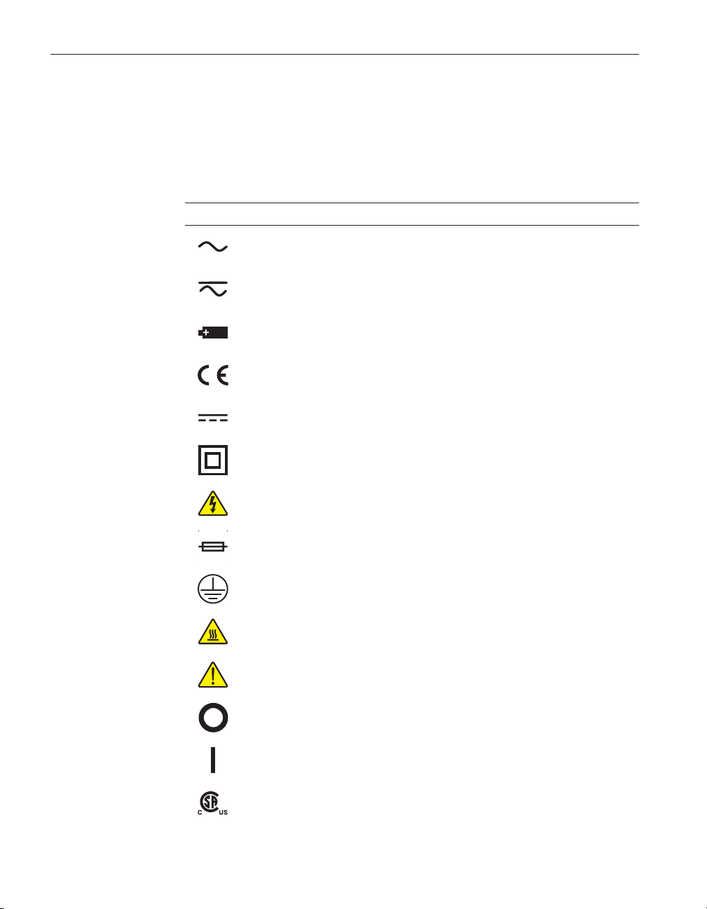
1.2 Symbols Used
Table 1 lists the International Electrical Symbols. Some or all of these symbols
may be used on the instrument or in this manual.
Table1 International Electrical Symbols
Symbol Description
AC (Alternating Current)
AC-DC
Battery
Complies with European Union directives
DC
Double Insulated
Electric Shock
Fuse
PE Ground
Hot Surface (Burn Hazard)
Read the User’s Manual (Important Information)
Off
On
Canadian Standards Association
2
Page 9

Symbol Description
OVERVOLTAGE (Installation) CATEGORY II, Pollution Degree 2 per IEC1010-1 re
fers to the level of Impulse Withstand Voltage protection provided. Equipment of
OVERVOLTAGE CATEGORY II is energy-consuming equipment to be supplied from
the fixed installation. Examples include household, office, and laboratory appliances.
C-TIC Australian EMC Mark
The European Waste Electrical and Electronic Equipment (WEEE) Directive
(2002/96/EC) mark.
1.3 Safety Information
Use this instrument only as specified in this manual. Otherwise, the protection
provided by the instrument may be impaired. Refer to the safety information in
the Warnings and Cautions sections below.
The following definitions apply to the terms “WARNING” and “CAUTION”.
• “Warning” identifies conditions and actions that may pose hazards to the
user.
• “Caution” identifies conditions and actions that may damage the instrument being used.
1 Before You Start
Safety Information
-
1.3.1
WARNINGS
To avoid personal injury, follow these guidelines.
GENERAL
•
DO NOT use this instrument in environments other than those listed in
the User’s Guide.
•
Inspect the instrument for damage before each use. DO NOT use the in
strument if it appears damaged or operates abnormally.
•
Follow all safety guidelines listed in the user’s manual.
•
Calibration Equipment should only be used by Trained Personnel.
•
If this equipment is used in a manner not specified by the manufacturer,
the protection provided by the equipment may be impaired.
•
Before initial use, or after transport, or after storage in humid or semi-hu
mid environments, or anytime the dry-well has not been energized for
more than 10 days, the instrument needs to be energized for a "dry-out"
period of 2 hours before it can be assumed to meet all of the safety re
quirements of the IEC 1010-1. If the product is wet or has been in a wet
environment, take necessary measures to remove moisture prior to apply
ing power such as storage in a low humidity temperature chamber operat
ing at 50°C for 4 hours or more.
-
-
-
-
-
3
Page 10

9011 Dual-Well Calibrator
User’s Guide
•
•
•
•
•
BURN HAZARDS
•
•
• Use of this instrument at HIGH TEMPERATURES for extended periods
• DO NOT touch the well access surface of the instrument.
• The block vent may be very hot due to the fan blowing across the heater
• The temperature of the well access is the same as the actual display tem-
• For top loading dry-wells, the top sheet metal of the dry-well may exhibit
•
•
•
DO NOT use this instrument for any application other than calibration
work. The instrument was designed for temperature calibration. Any other
use of the instrument may cause unknown hazards to the user.
Completely unattended operation is not recommended.
Overhead clearance is required. DO NOT place the instrument under a
cabinet or other structure. Always leave enough clearance to allow for
safe and easy insertion and removal of probes.
If the instrument is used in a manner not in accordance with the equip
ment design, the operation of the dry-well may be impaired or safety haz
ards may arise.
This instrument is intended for indoor use only.
DO NOT turn the instrument upside down with the inserts in place; the
inserts will fall out.
DO NOT operate near flammable materials.
of time requires caution.
block of the dry-well.
perature, e.g. if the instrument is set to 375°C and the display reads
375°C, the well is at 375°C.
extreme temperatures for areas close to the well access.
The air over the well can reach temperatures greater that 200°C for high
temperature (400°C and higher) dry-wells. Note: Probes and inserts may
be hot and should only be inserted and removed from the instrument
when the instrument is set at temperatures less than 50°C. Use extreme
care when removing hot inserts.
DO NOT turn off the instrument at temperatures higher than 100°C. This
could create a hazardous situation. Select a set-point less than 100°C and
allow the instrument to cool before turning it off.
The high temperatures present in dry-wells designed for operation at
300°C and higher may result in fires and severe burns if safety precau
tions are not observed.
-
ELECTRICAL SHOCK
•
These guidelines must be followed to ensure that the safety mechanisms
in this instrument will operate properly. This instrument must be plugged
into a 115 VAC, 60Hz (230 VAC, 50Hz optional), AC only electric outlet.
The power cord of the instrument is equipped with a three-pronged
4
Page 11

1 Before You Start
Safety Information
grounding plug for your protection against electrical shock hazards. It
must be plugged directly into a properly grounded three-prong receptacle.
The receptacle must be installed in accordance with local codes and ordi
nances. Consult a qualified electrician. DO NOT use an extension cord or
adapter plug.
If supplied with user accessible fuses, always replace the fuse with one of
•
the same rating, voltage, and type.
Always replace the power cord with an approved cord of the correct rat
•
ing and type.
HIGH VOLTAGE is used in the operation of this equipment. SEVERE
•
INJURY or DEATH may result if personnel fail to observe safety precau
tions. Before working inside the equipment, turn power off and discon
nect power cord.
-
-
-
-
1.3.2
CAUTIONS
Always operate this instrument at room temperature between 41°F and
•
122°F (5°C to 50°C). Allow sufficient air circulation by leaving at least 6
inches (15 cm) of clearance around the instrument.
• Component lifetime can be shortened by continuous high temperature op -
eration.
• DO NOT apply any type of voltage to the display hold terminals. Apply-
ing a voltage to the terminals may cause damage to the controller.
• DO NOT use fluids to clean out the well. Fluids could leak into electron-
ics and damage the instrument.
• Never introduce any foreign material into the probe hole of the insert.
Fluids, etc. can leak into the instrument causing damage.
•
DO NOT change the values of the calibration constants from the factory
set values. The correct setting of these parameters is important to the
safety and proper operation of the calibrator.
•
DO NOT slam the probe sheath in to the well. This type of action can
cause a shock to the sensor and affect the calibration.
•
The instrument and any thermometer probes used with it are sensitive in
struments that can be easily damaged. Always handle these devices with
care. DO NOT allow them to be dropped, struck, stressed, or overheated.
•
The Factory Reset Sequence (see Section , Troubleshooting) should be
performed only by authorized personnel if no other action is successful in
correcting a malfunction. You must have a copy of the most recent Report
of Calibration to restore the calibration parameters.
•
DO NOT operate this instrument in an excessively wet, oily, dusty, or
dirty environment. Always keep the well and inserts clean and clear of
foreign material.
•
The dry-well is a precision instrument. Although it has been designed for
optimum durability and trouble free operation, it must be handled with
-
5
Page 12

9011 Dual-Well Calibrator
User’s Guide
•
•
•
1.4 Authorized Service Centers
Please contact one of the following authorized Service Centers to coordinate
service on your Hart product:
Fluke Corporation, Hart Scientific Division
care. Always carry the instrument in an upright position to prevent the
probe sleeves from dropping out. The convenient handle allows for hand
carrying the instrument.
If a mains supply power fluctuation occurs, immediately turn off the in
strument. Power bumps from brown-outs could damage the instrument.
Wait until the power has stabilized before re-energizing the instrument.
Allow for probe expansion inside the well as the block heats.
Most probes have handle temperature limits. Be sure that the probe handle
temperature limit is not exceeded in the air above the instrument.
799 E. Utah Valley Drive
American Fork, UT 84003-9775
USA
Phone: +1.801.763.1600
Telefax: +1.801.763.1010
E-mail: support@hartscientific.com
Fluke Nederland B.V.
Customer Support Services
Science Park Eindhoven 5108
5692 EC Son
NETHERLANDS
Phone: +31-402-675300
Telefax: +31-402-675321
E-mail: ServiceDesk@fluke.nl
Fluke Int'l Corporation
Service Center - Instrimpex
Room 2301 Sciteck Tower
22 Jianguomenwai Dajie
Chao Yang District
Beijing 100004, PRC
6
Page 13

1 Before You Start
Authorized Service Centers
CHINA
Phone: +86-10-6-512-3436
Telefax: +86-10-6-512-3437
E-mail: xingye.han@fluke.com.cn
Fluke South East Asia Pte Ltd.
Fluke ASEAN Regional Office
Service Center
60 Alexandra Terrace #03-16
The Comtech (Lobby D)
118502
SINGAPORE
Phone: +65 6799-5588
Telefax: +65 6799-5588
E-mail: antng@singa.fluke.com
When contacting these Service Centers for support, please have the following
information available:
• Model Number
• Serial Number
• Voltage
•
Complete description of the problem
7
Page 14

2 Specifications and Environmental Conditions
2 Specifications and Environmental
Conditions
2.1 Specifications
Hot Block Cold Block
Range 50°C to 670°C (122°F to 1238°F) –30°C to 140°C (–22°F to 284°F)
Accuracy ±0.2°C at 50°C
Stability ±0.02°C at 100°C
Uniformity ±0.2°C (±0.05°C typical) ±0.05°C (insert wells)
Well Depth 6" (152 mm) 4.875" (124 mm)
HeatingTimetoMax. 30 minutes 15 minutes
Cooling Times 120 minutes from 660°C to 100°C 30 minutes from 140°C to –30°C
Well Inserts 1 interchangeable well accommodates
Computer Interface RS-232 interface included with Model 9930 Interface
Power 115 VAC (±10%), 8.8 A or 230 VAC (±10%), 4.4 A, switchable, 50/60 Hz, 1150
Size 11.5" H x 15.5" W x 10.5" D (292 x 394 x 267 mm)
Weight 36 lb. (16.4 kg)
NIST-Traceable Certificate
(8 points)
Safety OVERVOLTAGE (Installation) CATEGORY II, Pollution Degree 2 per
Fault Protection Sensor burnout protection, over-temperature cutout, and electrical fuses
Fuses 115 V: 10 A F (Hot), 4 A T (Cold), 250 VAC
†
Using same type of probes
±0.4°C at 400°C
±0.65°C at 600°C
±0.06°C at 600°C
multi-hole insert
W
Data at 50°C, 100°C, 200°C, 300°C,
400°C, 500°C, 600°C, and 660°C
IEC1010-1
230 V: 5 A F (Hot), 3.15 A T (Cold), 250 VAC
±0.25°C (insert wells)
±0.65°C (fixed wells)
±0.25°C (fixed wells)
1 interchangeable well accommodates
multi-hole insert, plus four outer wells,
1/4", 1/4", 3/16", and 1/8"
Data at –30°C, 0°C, 25°C, 50°C,
75°C, 100°C, 125°C, and 140°C
Specifications
±0.02°C at –30°C
±0.04°C at 140°C
-it
control software
2.2 Environmental Conditions
Although the instrument has been designed for optimum durability and trou
ble-free operation, it must be handled with care. The instrument should not be
operated in an excessively dusty or dirty environment. Maintenance and clean
ing recommendations can be found in the Maintenance Section of this manual.
The instrument operates safely under the following conditions:
•
temperature range: 5–50°C (41–122°F)
-
-
9
Page 15

9011 Dual-Well Calibrator
User’s Guide
•
•
•
•
•
•
2.3 Warranty
Fluke Corporation, Hart Scientific Division (Hart) warrants this product to be
free from defects in material and workmanship under normal use and service
for a period as stated in our current product catalog from the date of shipment.
This warranty extends only to the original purchaser and shall not apply to any
product which, in Hart’s sole opinion, has been subject to misuse, alteration,
abuse or abnormal conditions of operation or handling.
Software is warranted to operate in accordance with its programmed instructions on appropriate Hart products. It is not warranted to be error free.
Hart’s obligation under this warranty is limited to repair or replacement of a
product which is returned to Hart within the warranty period and is determined,
upon examination by Hart, to be defective. If Hart determines that the defect or
malfunction has been caused by misuse, alteration, abuse or abnormal conditions or operation or handling, Hart will repair the product and bill the purchaser for the reasonable cost of repair.
To exercise this warranty, the purchaser must forward the product after calling
or writing an Authorized Service Center (see Section 1.4). The Service Centers
assume NO risk for in-transit damage.
THE FOREGOING WARRANTY IS PURCHASER’S SOLE AND EXCLU
SIVE REMEDY AND IS IN LIEU OF ALL OTHER WARRANTIES, EX
PRESS OR IMPLIED, INCLUDING BUT NOT LIMITED TO ANY
IMPLIED WARRANTY OR MERCHANTABILITY, OR FITNESS FOR ANY
PARTICULAR PURPOSE OR USE. HART SHALL NOT BE LIABLE FOR
ANY SPECIAL, INDIRECT, INCIDENTAL, OR CONSEQUENTIAL DAM
AGES OR LOSS WHETHER IN CONTRACT, TORT, OR OTHERWISE.
ambient relative humidity: 15–50%
pressure: 75kPa–106kPa
mains voltage within ±10% of nominal
vibrations in the calibration environment should be minimized
altitudes less than 2000 meters
indoor use only
-
-
-
10
Page 16

3 Quick Start
3.1 Unpacking
3 Quick Start
Unpacking
Unpack the dry-well carefully and inspect it for any damage that may have oc
curred during shipment. If there is shipping damage, notify the carrier
immediately.
Verify that the following components are present:
9011 Dry-well
•
Power Cord
•
User's Guide with Report of Calibration
•
2 inserts
•
Insert removal tool
•
RS-232 Cable
•
• 9930 Interface-it Software
3.2 Set-up
Place the calibrator on a flat surface with at least 6 inches of free space around
the instrument. Always leave enough clearance in front of the instrument to allow for safe and easy insertion and removal of probes. Plug the power cord into
a grounded mains outlet. Observe that the nominal voltage corresponds to that
indicated on the calibrator.
3.3 Power
Plug the instrument power cord into a mains outlet of the proper voltage, fre
quency, and current capability. Refer to Section 2.1, Specifications, for the
power details.
Turn on the power to the calibrator by toggling both power switches on within
three seconds of each other. The fans should begin blowing air through the in
strument and both controller displays should illuminate after 3 seconds. After a
brief self-test the controller should begin normal operation. If the unit fails to
operate please check the power connection.
-
-
-
NOTE: If more than three seconds elapse,
pears on the display. Press any front control panel button to eliminate the
message. The hot block serial commands are not available unless
both power switches were turned on within three seconds of each other.
The display shows the well temperature and the well heater brings the tempera
ture of the well to the set-point temperature.
(Interconnect Link) ap
-
-
11
Page 17

9011 Dual-Well Calibrator
User’s Guide
After using the calibrator, allow the well to cool by setting the temperature to
25°C and waiting 1/2 hour before turning the instrument off.
3.4 Setting the Temperature
Section 6.2 explains in detail how to set the temperature set-point on the cali
-
brator using the front panel keys. The procedure is summarized here.
(1) Press “SET” twice to access the set-point value.
(2) Press “UP” or “DOWN” to change the set-point value.
(3) Press “SET” to program in the new set-point.
(4) Press and hold “EXIT” to return to the temperature display.
When the set-point temperature is changed the controller switches the well
heater on or off to raise or lower the temperature. The displayed well tempera
ture gradually changes until it reaches the set-point temperature. The well may
require considerable time to reach the set-point depending on the span. Addi
-
tional time is required to stabilize within ±0.1°C of the set-point.
-
12
Page 18

4 Parts and Controls
The user should become familiar with the dry-well calibrator and its parts (See
Figures 1, 2, and 3).
4.1 Rear Panel
Power Cord - The removable power cord (not shown), attaches to the back
side of the instrument. It plugs into a standard 115 VAC (optional 230 VAC)
grounded socket.
4 Parts and Controls
Rear Panel
Figure 1 Back Panel
RS-232 - The RS-232 serial port provides a means for connecting the instru
ment to a computer or a printer using the included serial cable.
Fan - The fans inside the instrument are controlled by the controller and vary
in speed. Slots at the top and bottom of the instrument are provided for airflow.
-
13
Page 19

9011 Dual-Well Calibrator
User’s Guide
The area around the calibrator must be kept clear to allow adequate ventilation.
The air is directed from the bottom to the top and may be hot. Allow 6 inches
of open space around the calibrator to allow adequate ventilation.
Fuse Holders - On the rear panel are four user accessible fuse holders.
WARNING: Always leave enough clearance to allow for safe and easy
installation and removal of probes.
4.2 Front Panel
Power Switches - The power switches for both controllers are located on the
front panel of the instrument. The switches are either on or off. The on position
is for normal operation. The off position disconnects power to the entire unit.
Controller Display - The digital display is an important part of the temperature
controller because it not only displays set and actual temperatures but also vari
ous calibrator functions, settings, and constants. The display shows temperatures in units according to the selected scale °C or °F.
Controller Keypad - The four button keypad allows easy setting of the
set-point temperature. The control buttons (SET, DOWN, UP, and EXIT) are
used to set the calibrator temperature set-point, access and set other operating
parameters, and access and set calibration parameters.
-
Figure 2 Front Panel
14
Setting the control temperature is done directly in degrees of the current scale.
It can be set to one-tenth of a degree Celsius or Fahrenheit.
The functions of the buttons are as follows:
SET - Used to display the next parameter in the menu and to store parameters
to the displayed value.
DOWN - Used to decrement the displayed value of parameters.
UP - Used to increment the displayed value.
EXIT - Used to exit a function and to skip to the next function. Any changes
made to the displayed value are ignored.
Page 20

4 Parts and Controls
4.3 Top Panel
Wel l Block - The well block openings are located on the top of both the cold
and hot sides. These openings are for insertion of interchangeable inserts. The
inserts are designed to accept probes of varying diameters. For insert details see
Section 4.4, Constant Temperature Block Assembly.
Display Hold - One set of Display Hold connectors are available for each
block. These connectors allow external switches to be connected and controlled
by the instrument.
4.4 Constant Temperature Block Assembly
Top Panel
The contant temperature block assemblies provide a relatively constant and ac
curate temperature environment for sensors to be calibrated. High-temperature
platinum RTDs imbedded in the block assemblies senses and control the tem
perature of the blocks. Inserts for use in the constant temperature block assem
bliesareshowninFigure3.
Warning: The air over the constant temperature block assembly can reach
temperatures greater that 200°C for high temperature (400°C and higher)
dry-wells. Probes and inserts may be hot and should only be inserted and
removed from the instrument when the instrument is set at temperatures
less than 50°C. Use extreme care when removing hot inserts.
Insert “A” has six holes that accept probe diameters of 1/16", 1/8, 3/16, 1/4",
3/8", and 1/2".
Insert “B” has six holes, two of each that accept probe diameters of 3/16",
1/4", and 3/8".
Insert “C” has six holes (cold) or eight holes (hot) that accept probe diameters
of 1/4".
Insert “D” has six holes, two that accept probe diameter of 3 mm, two that ac
cept probes of 4 mm diameter, and two that accept probes of 6 mm diameter.
-
-
-
-
15
Page 21

9011 Dual-Well Calibrator
User’s Guide
3/16"
(4.8 mm)
1/4"
(6.35 mm)
Hot Block
Removable
Insert Well
1.45" (37 mm)
I.D.
Cold Block
Removable
Insert Well
1.25" (32 mm)
I.D.
1/8"
(3.2 mm)
3/16"
(4.8 mm)
1/16" (1.6 mm)
1/2" (12.7 mm)
1/8" (3.2 mm)
1/4"
(6.35 mm)
Figure 3 Interchangeable Insert Options
Insert “A”
Insert “C”
1/4" (6.35 mm)
3/8" (9.5 mm)
3/16" (4.8 mm)
Cold block insert shown
(Hot block “C” insert
includes eight 1/4" wells)
3/16" (4.8 mm)
3/8" (9.5 mm)
1/4" (6.35 mm)
6 mm
3 mm
4 mm
Insert “B”
Insert “D”
1/4" (6.35 mm)
3/8" (9.5 mm)
3/16" (4.8 mm)
4 mm
6 mm
3 mm
16
Page 22

5 General Operation
5.1 Setting the Temperature
5 General Operation
Setting the Temperature
Section 6.2 explains in detail how to set the temperature set-point on the cali
brator using the front panel keys. The procedure is summarized here.
(1) Press “SET” twice to access the set-point value.
(2) Press “UP” or “DOWN” to change the set-point value.
(3) Press “SET” to program in the new set-point.
(4) Press and hold “EXIT” to return to the temperature display.
When the set-point temperature is changed the controller switches the well
heater on or off to raise or lower the temperature. The displayed well tempera
ture gradually changes until it reaches the set-point temperature. The well re
quires considerable time to reach the set-point depending on the span.
Additional time is required to stabilize within ±0.1°C of the set-point.
5.2 Changing Display Units
This instrument can display temperature in Celsius or Fahrenheit. The temperature units are shipped from the factory set to Celsius.
1 - Press “SET” three times from the temperature display to show
Un= C
2 - Press “UP” or “DOWN” to change units.
3 - Press “SET” to save the setting or “EXIT” to continue without changing the
setting.
-
-
-
17
Page 23

6 Controller Operation
6 Controller Operation
Well Temperature
This chapter discusses in detail how to operate the dry-well temperature con
troller using the front control panel. Using the front panel key-switches and
LED display the user may monitor the well temperature, set the temperature
set-point in degrees C or F, monitor the heater output power, adjust the control
ler proportional band, and program the calibration parameters, operating pa
rameters, and serial interface configuration. Operation of the functions and
parameters are shown in the flowchart in Figure 4 on page 20. This chart may
be copied for reference.
In the following discussion a button with the word SET, EXIT, UP, or DOWN
indicates the panel button, while the dotted box indicates the display reading.
Explanations of the button or display reading are to the right of each button or
display value.
6.1 Well Temperature
The digital LED display on the front panel allows direct viewing of the actual
well temperature. This temperature value is normally shown on the display. The
units, C or F, of the temperature value are displayed at the right. For example,
100.00C Well temperature in degrees Celsius
The temperature display function may be accessed from any other function by
pressing and holding the “EXIT” button.
6.2 Temperature Set-point
The temperature set-point can be set to any value within the range and with res
olution as given in the specifications. Be careful not to exceed the safe upper
temperature limit of any device inserted into the well.
Setting the temperature involves selecting the set-point memory and adjusting
the set-point value.
-
-
-
-
6.2.1 Programmable Set-points
The controller stores 8 set-point temperatures in memory. The set-points can be
quickly recalled to conveniently set the calibrator to a previously programmed
temperature set-point.
To set the temperature, first select the set-point memory. This function is ac
cessed from the temperature display function by pressing “SET”. The number
of the set-point memory currently being used is shown at the left on the display
followed by the current set-point value.
100.00C Well temperature in degrees Celsius
-
19
Page 24

9011 Dual-Well Calibrator
User’s Guide
Operating
Parameters
Menu
SET
HL
Adj. HL
SET/EXIT
Enable Switch Status
Disable Switch Status
Set-Point Resistance
EXIT
SET
SET/EXIT
Program Menu
SET
Number of Setpoints
SET
Select SetpointSelect Setpoint
EXIT
Soak Time
SET
Program Function Mode
EXIT
Program Control
Display
Temperature
SET
Select Setpoint
SET/EXIT
Adjust Setpoint
SET/EXIT
Units °C/°F
SET/EXIT
Scan On/Off
SET/EXIT
Scan Rate
SET/EXIT
EXIT
Secondary Functions
SET
DOWN
+
SET
DOWN
+
SET
+
EXIT
Display Power
SET/EXIT
Set Proportional Band
SET/EXIT
UP
UP
Configuration Menu
SET
Menu Legend:
Press “SET” to step through the menu and
to store the parameter value.
Press “EXIT” briefly to skip a parameter
without storing the parameter value.
Hold “EXIT” ( 2 seconds) to exit the menu
»
and display the temperature
†
Cold side only
‡
Hot side only
DO NOT CHANGE THESE VALUES
DO NOT CHANGE THESE VALUES
EXIT
Cal
Cal
Menu
Menu
SET
SET
Hard
Hard
Cutout
Cutout
SET/EXIT
SET/EXIT
Select R0
Select R0
Adjust R0
Adjust R0
SET/EXIT
SET/EXIT
Select ALPHA
Select ALPHA
Adjust ALPAH
Adjust ALPAH
SET/EXIT
SET/EXIT
Select DELTA
Select DELTA
Adjust DELTA
Adjust DELTA
SET/EXIT
SET/EXIT
Select BETA
Select BETA
Adjust BETA
Adjust BETA
SET/EXIT
SET/EXIT
x 5
x 5
Hot Side Only
‡
‡
†
†
Cold Side Only
†
†
EXIT
UP
DOWN
EXIT
EXIT
Serial
Interface
Menu
SET
Baud
Rate
Adjust
Baud Rate
SET/EXIT
Sample
Period
Adj. Sample
Period
SET/EXIT
Duplex
Mode
Adj. Duplex
Mode
SET/EXIT
Linefeed
Adjust
Linefeed
SET/EXIT
UP
DOWN
†
Cold Side Only
†
†
†
Cold Side Only
†
†
Figure 4 Controller Operation Flow Chart
20
Page 25

6 Controller Operation
Temperature Set-point
S
Access set-point memory
1 100. Set-point memory 1 location, 100°C currently used
To change to another set-point memory press “UP” or “DOWN”.
4 300. New set-point memory 4 location, 300°C
Press “SET” to accept the new selection and access the set-point value. Press
“EXIT” to continue and to ignore any changes.
S
Accept selected set-point memory
6.2.2 Set-point Value
The set-point value may be adjusted after selecting the set-point memory and
pressing “SET”.
4 200. Set-point 4 value in°C
If the set-point value does not need to be changed, press and hold “EXIT” to resume displaying the well temperature. To change the set-point value, press
“SET” and then “UP”.
220.00 New set-point value
When the desired set-point value is reached, press “SET” to accept the new
value and access the temperature scale units selection. If “EXIT” is pressed,
any changes made to the set-point are ignored.
S
Accept new set-point value
6.2.3 Temperature Scale Units
The temperature scale units of the controller maybe set by the user to degrees
Celsius (°C) or Fahrenheit (°F). The units are used in displaying the well tem
perature, set-point, proportional band, and high limit.
Press “SET” after adjusting the set-point value to change display units.
Un= C Scale units currently selected
Press “UP” or “DOWN” to change the units.
Un= F New units selected
Press “SET” to accept the new units or “EXIT” to cancel.
-
21
Page 26

9011 Dual-Well Calibrator
User’s Guide
6.3 Scan
The scan rate can be set and enabled so that when the set-point is changed the
dry-well heats or cools at a specified rate (degrees per minute) until it reaches
the new set-point. With the scan disabled the dry-well heats or cools at the
maximum possible rate.
6.3.1 Scan Control
The scan is controlled with the scan on/off function that appears in the main
menu after the temperature scale units.
Sc=OFF Current scan setting
Press “UP” or “DOWN” to toggle the scan on or off.
Press “SET” to accept the present setting and continue.
Sc=On Scan function on
S
Accept scan setting
6.3.2 Scan Rate
The scan rate can be set from 0.1 to 50.0°C/min. The maximum scan rate, however, is actually limited by the natural heating or cooling rate of the instrument.
This rate is often less than 50°C/min, especially when cooling.
The scan rate function appears in the main menu after the scan control function.
The scan rate units are in degrees Celsius per minute, regardless of the selected
units.
Sr=2.0 Current scan rate setting in °C/min
Press“UP”or“DOWN”tochangethescanrate.
Sr=3.0 New scan rate
Press “SET” to accept the new scan rate and continue.
S
Accept scan rate
6.4 Temperature Display Hold
There are two sets of display hold terminals located on the top of the 9011, one
for the cold side and one for the hot side. The display hold terminals are used
for testing thermal switches.
22
Page 27

6 Controller Operation
Temperature Display Hold
CAUTION: Do not apply any type of voltage to the display hold termi
nals. Applying a voltage to the terminals may cause damage to the con
troller.
6.4.1 Switch Status
Connect the thermal switch to the display hold terminals on the either the hot or
cold side. To enable the Switch Status while displaying the temperature, press
"UP" on the hot or cold side. The letter "o" (switch open) or "c" (switch
closed) appears to the left of the display and flashes when it changes states.
When the Switch Status is enabled, the displayed temperature does not show
the hundredth place or the units. (For example, if the switch is open and the
temperature is 25°C, "o 25.0" is displayed.) To disable the Switch Status,
press the "DOWN" key.
When the Switch Status is displayed, the Display Hold is also enabled, allow
ing the operator to view the temperature at which the switch changed states and
the status of the thermal switch.
When the thermal switch changes states the controller does the following.
1. Displays the temperature at which the switch changed states.
2. Flashes the new switch status.
3. The controller continues in the above state until either the thermal switch
is returned to its original state or the set-point temperature changes.
Note: This feature is a useful to quickly monitor thermal switch state changes
with a rough idea of accuracy but is not accurate when compared with the displayed temperature. Enable Scan Hold (see Section 6.4.2, Scan Hold) to improve the accuracy.
The following example demonstrates the use of Switch Status using the Display
Hold terminals.
-
-
-
Example 1
With the instrument displaying 25°C, set the set-point to 100°C and enable the
Switch Status by pressing "UP". When the thermal switch changes states at say
50°C, the displayed temperature shows 50°C and the status flashes "o or c",
while the block continues to 100°C. The display remains at the switched tem
perature and "o or c" continues to flash until the switch changes status or a
new set-point is set.
6.4.2 Scan Hold
To enable scan hold, first enable Switch Status/Display Hold and the Scan Con
trol (see Section 6.3.1, Scan Control)prior to setting the set-point temperature.
Scan Hold is similar to Switch Status/Display Hold but instead of displaying
the temperature at which the thermal switch changes status, it sets a new
set-point temperature to the current temperature at which the thermal switch
-
-
23
Page 28

9011 Dual-Well Calibrator
User’s Guide
changed states. This feature allows for minimal block temperature scanning
times and improved accuracy.
Example 2:
With the instrument displaying 25°C, set the set-point to 100°C and enable the
Scan Hold feature. When the thermal switch changes states at 50°C, the con
troller automatically sets a new set-point of 50°C and the status flashes either
"o or c".
-
Note: There is a delay between the displayed temperature and the actual tem
perature of the thermal switch. To achieve better accuracy when the thermal
switch is tripped, the scan rate should be set for a slower time. The slower the
scan rate the more time required to perform a test. The operator must determine
the optimal scan rate for the specific application.
6.5 Ramp and Soak Program Menu
The ramp and soak program feature allows the user to program a number of
set-points and have the dry-well automatically cycle between the temperatures,
holding at each for a determined length of time. The user can select one of four
different cycle functions.
The program parameter menu is accessed by pressing “SET” and then “UP”.
20.00C Well temperature
S+U
ProG Program menu
Press “SET” to enter the program menu
S
Access program menu
Enter program menu
-
24
6.5.1 Number of Program Set-points
The first parameter in the program menu is the number of set-points to cycle
through. Up to 8 set-points can be used in a ramp and soak program.
Pn=8 Number of program set-points
Use the “UP” or “DOWN” buttons to change the number from 2 to 8.
Pn=3 New number of program set-points
Press “SET” to continue. Pressing “EXIT” causes any changes made to the pa
rameter to be ignored.
-
Page 29

6 Controller Operation
Ramp and Soak Program Menu
S
Save new setting
6.5.2 Set-points
The next parameters are the program set-points.
1 25 First set-point
Use the “UP” or “DOWN” buttons to select any of the set-points.
3 10 Third set-point
Press “SET” to change the set-point.
10.00 Set-point value
Use “UP” and “DOWN” to change the set-point value.
13.50 New set-point value
Press “SET” to save the new set-point value.
The other set-points can also be set in the same manner. Once the set-points are
programmed as desired press “EXIT” to continue.
E
Continue to next menu function
6.5.3 Program Soak Time
The next parameter in the program menu is the soak time. This is the time, in
minutes, for which each of the program set-points is maintained after settling
before proceeding to the next set-point. The duration is counted from the time
the temperature settles to within a specified stability.
Pt=15 Soak time in minutes
Use“UP”or“DOWN”tochangethetime.
Pt=5 New soak time
Press “SET” to continue.
S
Save new setting
6.5.4 Program Function Mode
The next parameter is the program function or cycle mode. There are four pos
sible modes which determine whether the program scans up (from set-point 1
-
25
Page 30

9011 Dual-Well Calibrator
User’s Guide
to n) only or both up and down (from set-point n to 1), and also whether the
program stops after one cycle or repeat the cycle indefinitely. The table below
shows the action of each of the four program mode settings.
Function Action
1 up-stop
2 up-down-stop
3 up-repeat
4 up-down-repeat
Use the “UP” or “DOWN” buttons to change the mode.
Press “SET” to continue.
Pf=1 Program mode
Pf=4 New mode
S
Save new setting
6.5.5 Program Control
The final parameter in the program menu is the control parameter. Three options are available for controlling the ramp and soak program. The options are
“GO” (start the program from the beginning), “Cont” (continue the program
from where it was when it was stopped), or “OFF” stop the program.
P=OFF Program presently off
Use“UP”or“DOWN”tochangetheprogramstate.
Pr=Cont Start cycle from beginning
Press “SET” to activate the new program control command and return to the
temperature display.
S
Activate new command.
6.6 Set-point Resistance
The set-point resistance is the resistance the instrument is trying to make the
control sensor achieve and is calculated in the firmware using the set-point tem
perature. This value is not directly adjustable but is recalculated when the
set-point temperature is changed. The set-point resistance is used to perform a
calibration adjustment using the Callendar-Van Dusen R versus T curve fit. The
-
26
Page 31

6 Controller Operation
Secondary Menu
instrument must be at temperature and stable prior to taking the set-point resis
tance reading.
To display the Set-point Resistance, press “SET” and “DOWN” simultaneously
when the temperature is displayed. When the “SET” and “DOWN” buttons are
released the temperature is again displayed.
99.222 Current set-point resistance setting is displayed
6.7 Secondary Menu
Functions which are used less often are accessed within the secondary menu.
The secondary menu is accessed by pressing “EXIT” while holding down
“SET” and then releasing both. The first function in the secondary menu is the
heater power display.
6.8 Heater Power
The temperature controller controls the temperature of the well by pulsing the
heater on and off. The total power being applied to the heater is determined by
the duty cycle or the ratio of heater on time to the pulse cycle time. By knowing
the amount of heating, the user can tell if the calibrator is heating up to the
set-point, cooling down, or controlling at a constant temperature. Monitoring
the percent heater power, allows the user to know the stability of the well temperature. With good control stability the percent heating power should not fluctuate more than ±1% within one minute.
The heater power display is accessed in the secondary menu. Press “EXIT”
while holding down “SET” and then release both. The heater power is dis
played as a percentage of full power.
-
-
100.00C Well temperature
S+E
Access heater power in secondary menu
SEC Flashes SEC for secondary menu and then displays the
heater power
12.0P Heater power in percent
To exit out of the secondary menu press “EXIT”. To continue on to the propor
tional band setting function press “SET”.
-
27
Page 32

9011 Dual-Well Calibrator
User’s Guide
6.9 Proportional Band
In a proportional controller such as this, the heater output power is proportional
to the well temperature over a limited range of temperatures around the
set-point. This range of temperature is called the proportional band. At the bot
tom of the proportional band, the heater output is 100%. At the top of the pro
portional band, the heater output is 0 to 100 (hot side) and –100 to 100 (cold
side). Thus, as the temperature rises the heater power is reduced, which conse
quently tends to lower the temperature back down. In this way the temperature
is maintained at a fairly constant temperature.
The temperature stability of the well and response time depend on the width of
the proportional band. If the band is too wide, the well temperature deviates ex
cessively from the set-point due to varying external conditions. This is because
the power output changes very little with temperature and the controller cannot
respond very well to changing conditions or noise in the system. If the propor
tional band is too narrow, the temperature may swing back and forth because
the controller overreacts to temperature variations. For best control stability, the
proportional band must be set for the optimum width.
The proportional band width is set at the factory and printed on the Report of
-
-
-
-
-
28
Figure 5 Temperature fluctuations at various proportional band settings
Calibration. The proportional band width may be altered by the user if desired
to optimize the control characteristics for a particular application.
The proportional band width is easily adjusted from the front panel. The width
may be set to discrete values in degrees C or F depending on the selected units.
The proportional band adjustment is accessed within the secondary menu. Press
“EXIT” while holding down “SET” and then releasing both to enter the sec
ondary menu and show the heater power. Then press “SET” to access the pro
portional band.
S+E
Access heater power in secondary menu
-
-
Page 33

6 Controller Operation
Controller Configuration
SEC Flashes SEC for secondary menu and then displays the
heater power
12.0P Heater power in percent
S
Access proportional band
ProP Flashes and then displays the setting
4.1
To change the proportional band, press “UP” or “DOWN”.
10.0
To accept the new setting press “SET”. Press “EXIT” to continue without storing the new value.
S
Accept the new proportional band setting
Proportional band setting
New proportional band setting
6.10 Controller Configuration
The controller has a number of configuration and operating options and calibration parameters which are programmable via the front panel. These are accessed from the secondary menu after the proportional band function by
pressing “SET”. Pressing “SET” again enters the first of three sets of configuration parameters - operating parameters, serial interface parameters, and cali
bration parameters. The menus are selected using “UP” or “DOWN” and then
pressing “SET”.
-
6.11 Operating Parameters
The operating parameters menu is indicated by,
PAr Operating parameters menu
The operating parameters menu contains the High Limit parameter.
6.12 High Limit
The High Limit parameter adjusts the upper set-point temperature. The factory
default and maximum are set to the instrument temperature limit. For safety, a
user can adjust the High Limit down so the maximum temperature set-point is
restricted.
29
Page 34

9011 Dual-Well Calibrator
User’s Guide
Press “UP” or “DOWN” to adjust the setting.
HL Flashes and then displays the setting
H=375 Current High Limit setting
H=300 New High Limit setting
To accept the new setting, press “SET”. Press “EXIT” to continue without stor
ing the new value.
S
Accept the new High Limit setting
6.13 Serial Interface Parameters
Note: Both sides of the 9011 must be turned on within three seconds of one an
other for the serial communications to function on the hot side. If “ICL” is displayed on either the hot or the cold side of the instrument, the serial port is not
controlled by the hot side. If “ICL” is displayed and control is desired from
only the front panel, press any button (“SET”, “UP”, “DOWN”, or “EXIT”) to
remove “ICL” from the display and control the instrument from the front panel
buttons only.
This instrument has two controllers, one for the hot side and one for the cold
side. The cold side controller acts as the master for the serial communications
and the hot side controller acts as the slave.
The serial RS-232 interface parameters menu is indicated by,
SErIAL Serial RS-232 interface parameters menu
Press “SET” to enter the menu. The serial interface parameters menu contains
parameters which determine the operation of the serial interface. The parame
ters in the menu are - BAUD rate, sample period, duplex mode, and linefeed.
-
-
-
30
6.13.1 Baud Rate (cold side only)
The baud rate is the first parameter in the menu. The baud rate setting deter
mines the serial communications transmission rate.
The baud rate parameter is indicated by,
bAUd Flashes for one second and then displays the setting
2400 b Current baud rate
-
Page 35

The baud rate of the serial communications may be programmed to 300, 600,
1200, 2400 (default), 4800, or 9600 baud. Use “UP” or “DOWN” to change the
baud rate value.
4800 b New baud rate
Press “SET” to accept the new setting or “EXIT” to abort the operation and
skip to the next parameter in the menu.
6.13.2 Sample Period (hot and cold sides)
The sample period is the next parameter in the menu. The sample period is the
time period in seconds between temperature measurements transmitted over the
serial interface. If the sample period is set to 5, the instrument transmits the
current measurement over the serial interface approximately every five seconds.
The automatic sampling is disabled with a sample period of 0. The sample pe
riod is indicated by,
SPEr Flashes for one second and then the serial sample period
setting is displayed
SA=1 Current sample period (seconds)
6 Controller Operation
Serial Interface Parameters
-
Adjust the value by using “UP” or “DOWN”.
SA=60 New sample period
Press “SET” to accept the new setting or “EXIT” to abort the operation and
skip to the next parameter in the menu.
6.13.3 Duplex Mode (cold side only)
The next parameter is the duplex mode. The duplex mode may be set to full du
plex or half duplex. With full duplex any commands received by the master
controller via the serial interface are immediately executed and echoed or trans
mitted back to the device of origin. With half duplex the commands are exe
cuted but not echoed. The duplex mode parameter is indicated by,
dUPL Flashes for one second and then the serial duplex mode
setting is displayed
d=FULL Current duplex mode setting
The mode may be changed using “UP” or “DOWN”.
d=HALF New duplex mode setting
-
-
-
31
Page 36

9011 Dual-Well Calibrator
User’s Guide
Press “SET” to accept the new setting or “EXIT” to abort the operation and
skip to the next parameter in the menu.
6.13.4 Linefeed (cold side only)
The final parameter in the menu is the linefeed mode. This parameter enables
(on) or disables (off) transmission of a linefeed character (LF, ASCII 10) after
transmission of any carriage-return. The linefeed parameter is indicated by,
The setting may be changed using “UP” or “DOWN”.
LF=OFF New linefeed setting
Press “SET” to accept the new setting or “EXIT” to abort the operation and
skip to the next parameter in the menu.
6.14 Calibration Parameters
LF Flashes for one second and then the serial linefeed setting
is displayed
LF=On Current linefeed setting
32
The operator of the instrument controller has access to a number of the calibration constants namely the Hard Cutout, R0, ALPHA, DELTA, and BETA.
These values are set at the factory and must not be altered. The correct values
are important to the accuracy and proper and safe operation of the instrument.
Access to these parameters is available to the user so that in the event that the
controller memory fails the user may restore these values to the factory set
tings. The user should have a list of these constants and their settings with the
instrument manual.
CAUTION: DO NOT change the values of the instrument calibration con
stants from the factory set values. The correct setting of these parameters
is important to the safety, proper operation, and performance of the in
strument.
The calibration parameters menu is accessed by pressing “UP” from the serial
interface menu and is indicated by the following.
-
-
-
CAL Calibration parameters menu
Press “SET” five times to enter the menu. The calibration parameters menu
contains the parameters, Hard Cutout, R0, ALPHA, DELTA, and BETA that
characterize the resistance-temperature relationship of the platinum control sen
sor. These parameters may be adjusted to improve the accuracy of the
calibrator.
-
Page 37

The calibration parameters are accessed by pressing “SET” after the name of
the parameter is displayed. The value of the parameter may be changed using
“UP” or “DOWN”. After the desired value is reached, press “SET” to set the
parameter to the new value. Pressing “EXIT” causes the parameter to be
skipped ignoring any changes that may have been made.
6.14.1 Hard Cutout (hot side only)
6 Controller Operation
Calibration Parameters
This parameter is the temperature above which the unit shuts down automati
cally and is only adjustable through the hot side. The value of this parameter is
set at the factory and cannot be changed by the user.
The hard cutout parameter is indicated by,
Press “EXIT” to continue to the next parameter.
6.14.2 R0
This probe parameter refers to the resistance of the control probe at 0°C. The
value of this parameter is set at the factory for best instrument accuracy. The
value ranges from 95 to 105. The R0 parameter is indicated by,
To change the R0 setting, press “UP” or “DOWN”.
-
CutOut Flashes for one second and then the hard cutout setting is
displayed
670 Current hard cutout setting
r0 Flashes for one second and then the R0 setting is displayed
100.014 Current R0 setting (100.014)
99.999 New R0 setting
To accept the new setting, press “SET”. Press “EXIT” to continue without stor
ing the new value.
S
6.14.3 ALPHA
This probe parameter refers to the average sensitivity of the probe between 0
and 100°C. The value of this parameter is set at the factory for best instrument
accuracy. (The ALPHA value is the displayed value times 10
aLpHa Flashes for one second and then the ALPHA setting is
Accept the new R0 setting
displayed
-
–7
.)
33
Page 38

9011 Dual-Well Calibrator
User’s Guide
38530 Current ALPHA setting
To change the ALPHA setting, press “UP” or “DOWN”.
38600 New ALPHA setting
To accept the new setting, press “SET”. Press “EXIT” to continue without stor
ing the new value.
S
Accept the new ALPHA setting
6.14.4 DELTA
This probe parameter characterizes the curvature of the resistance-temperature
relationship of the sensor. The value of this parameter is set at the factory for
best instrument accuracy.
deLta Flashes for one second and then the DELTA setting is
displayed
1.5070 Current DELTA setting
To change the DELTA setting, press “UP” or “DOWN”.
1.6320 New DELTA setting
To accept the new setting, press “SET”. Press “EXIT” to continue without storing the new value.
S
Accept the new DELTA setting
6.14.5 BETA (cold side only)
This probe parameter relates to the higher order nonlinearity of the sensor be
low 0°C. The value is set at the factory for best instrument accuracy.
-
-
34
bEtA Flashes for one second and then the BETA setting is
displayed
0.111 Current BETA setting
To change the BETA setting, press “UP” or “DOWN”.
0.100 New BETA setting
To accept the new setting, press “SET”. Press “EXIT” to continue without stor
ing the new value.
-
Page 39

6 Controller Operation
Calibration Parameters
S
Accept the new BETA setting
35
Page 40

7 Digital Communication Interface
7 Digital Communication Interface
This instrument is capable of communicating with and being controlled by
other equipment through the digital serial interface.
With a digital serial interface, the instrument may be connected to a computer
or other equipment. This allows the user to set the set-point temperature, moni
tor the temperature, and access any of the other controller functions, all using
remote communications equipment. Communications commands are summa
rized in Table 2 on page 40.
7.1 Serial Communications
The RS-232 serial interface allows serial digital communications over fairly
long distances (15.24 meters). With the serial interface the user may access any
of the functions, parameters and settings discussed in Section 6, Controller Op
eration with the exception of the BAUD rate setting. The serial interface oper
ates with eight data bits, one stop bit, and no parity.
7.1.1 Wiring
The serial communications cable attaches to the calibrator
through the DB-9 connector on
the back of the instrument. Figure 6 shows the pin-out of this
connector and suggested cable
wiring. To eliminate noise, the
serial cable should be shielded
with low resistance between the
connector (DB9) and the shield.
Serial Communications
-
-
-
-
7.1.2 Setup
Before operation the serial in
terface must first be set up by
programming the BAUD rate
and other configuration parame
ters. These parameters are pro
grammed within the serial
interface menu of the cold side
controller. The serial interface
parameters menu is outlined in
Figure 4 on page 20.
To enter the serial parameter
menu on the cold side control
ler, press “EXIT” while holding
-
-
-
-
Figure 6 Serial Cable Wiring
37
Page 41

9011 Dual-Well Calibrator
User’s Guide
down “SET”, then release both buttons to enter the secondary menu. Press
“SET” repeatedly until the display reads “PAr”. Press “UP” once, the serial in
terface menu is indicated with “SErIAL”. Finally press “SET” to enter the se
rial parameter menu. In the serial parameters menu are the baud rate, the
sample period, the duplex mode, and the linefeed parameter.
7.1.2.1 Baud Rate (Cold Side Only)
The baud rate is the first parameter in the menu and is indicated by “BAUd”.
Press “SET” to choose to set the baud rate. The current baud rate value is dis
played. The serial communications baud rate may be programmed to 300, 600,
1200, 2400, 4800, or 9600 baud. The baud rate is pre-programmed to 2400
baud. Use “UP” or “DOWN” to change the baud rate setting. Press “SET” to
accept the new setting or “EXIT” to abort the operation and skip to the next pa
rameter in the menu.
7.1.2.2 Sample Period
The sample period is the next parameter in the menu and is indicated by
“SPEr”. The sample period is the time period in seconds between temperature
measurements transmitted from the serial interface. If the sample period is set
to 5, the instrument transmits the current measurement over the serial interface
approximately every five seconds. The automatic sampling is disabled with a
sample period of 0. Press “SET” to choose to set the sample period. Adjust the
period with “UP” or “DOWN”. Press “SET” to save the new sample rate to the
displayed value or “EXIT” to abort the operation and skip to the next parameter
in the menu.
-
-
-
-
38
7.1.2.3 Duplex Mode
The next parameter is the duplex mode indicated with “dUPL”. The duplex
mode may be set to half duplex (HALF) or full duplex (FULL). With full duplex
any commands received by the controller via the serial interface are immedi
ately executed and echoed or transmitted back to the device of origin. With half
duplex the commands are executed but not echoed. The default setting is full
duplex. The mode may be changed using “UP” or “DOWN”. Press “SET” to
accept the new setting or “EXIT” to abort the operation and skip to the next pa
rameter in the menu.
7.1.2.4 Linefeed
The final parameter in the menu is the linefeed mode and is indicated by “LF”.
This parameter enables (“On”) or disables (“OFF”) transmission of a linefeed
character (LF, ASCII 10) after transmission of any carriage-return. The default
setting is with linefeed on. The mode may be changed using “UP” or
“DOWN”. Press “SET” to accept the new setting or “EXIT” to abort the opera
tion and return to the beginning of the serial interface menu.
-
-
-
Page 42

7.1.3 Serial Operation
The serial communications uses 8 data bits, one stop bit, and no parity. The
set-point and other commands may be sent via the serial interface to set the
temperature set-point and view or program the various parameters. The inter
face commands are discussed in Section 7.2. All commands are ASCII charac
ter strings terminated with a carriage-return character (CR, ASCII 13).
7.2 Interface Commands
7 Digital Communication Interface
Interface Commands
-
-
The various commands for accessing the calibrator functions via the digital se
rial interface are listed in this section (see Table 2 beginning on page 40). These
commands are used with the RS-232 serial interface. The commands are termi
nated with a carriage-return character (CR, ASCII 13). The interface makes no
distinction between upper and lower case letters, hence either may be used.
Commands may be abbreviated to the minimum number of letters which deter
mines a unique command. A command may be used to either set a parameter or
display a parameter depending on whether or not a value is sent with the com
mand following a “=” character. For example, an “s” <CR> returns the current
set-point and “s=50.0” <CR> sets the set-point to 50.0 degrees.
In the following list of commands, characters or data within brackets, “[” and
“]”, are optional for the command. A slash, “/”, denotes alternate characters or
data. Numeric data, denoted by “n”, may be entered in decimal or exponential
notation. Characters are shown in lower case although upper case may be used.
Spaces may be added within command strings and will simply be ignored.
Backspace (BS, ASCII 8) may be used to erase the previous character. A terminating (CR, ASCII 13) is implied with all commands.
Note: Commands that are preceded by a “C:” or an “H:” access the cold or hot
side respectively. If the “C:” or “H:” are not used, the command accesses the
cold side. It is highly recommended to always use “C:” or “H:” prefixes to en
sure setting or reading a parameter on the correct controller. Responses to com
mands do not indicate which controller the setting or reading applies to or came
from.
-
-
-
-
-
-
39
Page 43

9011 Dual-Well Calibrator
User’s Guide
Table 2 Controller Communications Commands
Command Description
Command
†
Format
Command
†
Example
Returned
Returned
Example
Acceptable
Values
Display Temperature
Read current set-point s[etpoint] s set: 9999.99 {C orF}set: 150.00 C
Set current set-point to n s[etpoint]=n s=450 Controller
Range
Read temperature unit u[nits] u u:{C or F} u:C
Set temperature units: u[nits]=c/f
CorF
Set temperature units to Celsius u[nits]=c u=c
Set temperature units to
u[nits]=f u=f
Fahrenheit
Read scan function sc[an] sc scan: {ON or OFF} scan: ON
Set scan function: sc[an]=on/of[f]
ON or OFF
Turn scan function on sc[an]=on sc=on
Turn scan function off sc[an]=of[f] sc=of
Read scan rate sr[ate] sr srat: 999.9 {C or
F}/min
Setscanrateto
n
degrees per
sr[ate]=
n
sr=5 0.1 to 50°C
srat: 10.0
C/min
minute
Read display temperature hold
hm[ode] hm hmode: AUTO hmode: AUTO
mode
Read hold status ho[ld] ho ho:{closed or
open}, 9999.9 {C or
ho: open,
75.0 C
F}
Read temperature t[emperature] t t: 9999.9 {C or F} t: 55.69 C
Secondary Menu
Read proportional band setting pr[op-band] pr pb: 999.99999 pb: 15.9
Set proportional band to
n
pr[op-band]=n pr=8.83 Depends on
Configuration
Read cutout setting c[utout] c cu: 9999 {C or F} cu: 620 C, in
Read heater power
po[wer] po po: 9999.9 po: 1.0
(duty cycle)
Ramp and Soak Menu
Read number of programmable
pn pn pn: 9 pn: 2
set-points
Set number of programmable
set-points to
n
Read programmable set-point
number
n
Set programmable set-point num
nton
ber
pn=
n
ps
n
-
psn=
n
pn=4 2 to 8
ps3 psn: 9999.99 {C orF}ps1: 50.00 C
ps3=50 1 to 8, Instru
ment Range
-
40
Page 44

Controller Communications Commands continued
7 Digital Communication Interface
Interface Commands
Command Description
Command
†
Format
Command
†
Example
Returned
Returned
Example
Acceptable
Values
Read program set-point soak time pt pt ti: 999 ti: 5
Set program set-point soak time to
n
minutes
pt=
n
pt=5 0 to 500
Read program control mode pc pc prog: {OFF or ON} prog: OFF
Set program control mode: pc=g[o]/s[top]/c[ont]
GO or STOP or
CONT
Start program pc=g[o] pc=g
Stop program pc=s[top] pc=s
Continue program pc=c[ont] pc=c
Read program function pf pf pf: 9 pf: 3
Set program function to
n
pf=
n
pf=2 1to4
Configuration Menu
Operating Parameters Menu
Read high limit hl hl hl:999 hl:126
Set high limit hl=n hl=90 Hot: 25 to
670°C
Cold: 25 to
140°C
Serial Interface Menu
Read serial sample setting sa[mple] sa sa: 999 sa: 1
Set serial sampling setting to
n
sa[mple]=
n
sa=0 0to999
seconds
Read serial duplex mode (cold
du[plex] du: du:{FULL of HALF} du: FULL
side only)
Set serial duplex mode: (cold
du[plex]=f[ull]/h[alf]
FULL or HALF
side only)
Set serial duplex mode to full du[plex]=f[ull] du=f
Set serial duplex mode to half du[plex]=h[alf] du=h
Read serial linefeed mode (cold
lf[eed] lf lf: ON
side only)
Set serial linefeed mode: (cold
lf[eed]=on/of[f]
ON or OFF
side only)
Set serial linefeed mode to on lf[eed]=on lf=on
Set serial linefeed mode to off lf[eed]=of[f] lf=of
Calibration Menu (WARNING – changing the following calibration values may change the accuracy of the instrument.)
Read R0 calibration parameter r[0] r r0: 999.999 r0: 100.578
Set R0 calibration parameter to
Read ALPHA calibration
n
r[0]=n r=100.324 95.0 to 105.0
al[pha] al al: 9.99999999 al: 0.0038573
parameter
41
Page 45

9011 Dual-Well Calibrator
User’s Guide
Controller Communications Commands continued
Command Description
Set ALPHA calibration parameter
to
n
Command
†
Format
al[pha]=n al=0.0038433 0.0032 to
Command
†
Example
Returned
Returned
Example
Acceptable
Values
0.0042
Read DELTA calibration parameter de[lta] de de: 9.99999 de: 1.46126
Set DELTA calibration parameter
to
n
Read BETA calibration parameter
de[lta]=
n
de=1.45 1.0 to 1.9
be[ta] be be: 9.999 be: 0.342
(cold side only)
Set BETA calibration parameter to
n
(cold side only)
be[ta]=
n
be=0.342 –25.0 to 25.0
Miscellaneous (not on menus)
Read firmware version number *ver[sion] *ver ver.9999,9.99 ver.9011,1.11
Read structure of all commands h[elp] h list of commands
Read all parameters all all list of parameters
and their values
Legend: [] Optional Command data
/ Alternate characters or data
{} Returns either information
n Numeric data supplied by user—may be entered in decimal or exponential notation
9 Numeric data returned to user
x Character data returned to user
Note: When DUPLEX is set to FULL and a command is sent to READ, the command is returned followed by
a carriage return and linefeed. Then the value is returned as indicated in the RETURNED column.
†
Note: Commands that are preceded by a “C:” or an “H:” access the cold or hot side respectively. If the “C:” or
“H:” are not used, the command accesses the cold side.
42
Page 46

8 Test Probe Calibration
For optimum accuracy and stability, allow the calibrator to warm up for 10
minutes after power-up and then allow adequate stabilization time after reach
ing the set-point temperature. After completing the test probe calibration proce
dure, allow the well to cool by setting the temperature to 25°C for one-half
hour before switching the power off. Actual use of this instrument should be
determined by your applicable Quality Assurance requirements. The following
procedure is provided for information only.
8.1 Calibrating a Single Probe
Insert the probe to be calibrated into the test well of the instrument. The probe
should fit snugly into the calibrator test well yet should not be so tight that it
cannot be easily removed. Avoid any dirt or grit that may cause the probe to
jam into the test well. Best results are obtained with the probe inserted to the
full depth of the test well. Once the probe is inserted into the test well, allow
adequate stabilization time to allow the test probe temperature to settle as described above. Once the probe has settled to the temperature of the test well, it
may be compared to the calibrator display temperature.
8 Test Probe Calibration
Calibrating a Single Probe
-
-
CAUTION: Never allow foreign material into the probe holes of the
block. Fluids and other materials can damage the instrument causing
binding and damage to your probe.
8.2 Dry-well Characteristics
There is a temperature gradient vertically in the test well. The heater has been
applied to the block in such a way as to compensate for nominal heat losses out
of the top of the dry-well. However, actual heat losses vary with design of the
thermometer probes inserted into the calibrator and the temperature. For best
results, insert probe to full depth of test well.
8.2.1 Stabilization and Accuracy
The stabilization time of the instrument depends on the conditions and temper
atures involved. The well requires considerable time to reach the set-point de
pending on the span. Additional time is required to stabilize within ±0.1°C of
the set-point.
Inserting a cold probe into a test well requires another period of stabilizing de
pending on the magnitude of the disturbance and the required accuracy. For ex
ample, inserting a 0.25 inch diameter room temperature probe into a test well at
300°C takes 5 minutes to be within 0.1°C of its settled point and takes 10 min
utes to achieve maximum stability.
-
-
-
-
-
43
Page 47

9011 Dual-Well Calibrator
User’s Guide
Speeding up the calibration process can be accomplished by knowing how soon
to make the measurement. It is recommended that typical measurements be
made at the desired temperatures with the desired test probes to establish these
times.
44
Page 48

9 Calibration Procedure
9.1 Calibration Procedure
9 Calibration Procedure
Calibration Procedure
Calibration of this instrument should be performed at regularly scheduled inter
vals by qualified authorized personnel in accordance with your company’s pol
icy. The following is provided as a basis for developing your own procedure for
calibrating this instrument.
9.1.1 Calibration Equipment
Calibration requires a standard thermometer that is adequately accurate and fits
properly into one of the reference holes in each of the blocks. Recommended
equipment includes a laboratory grade PRT with a length of 230 to 300 mm (9
to 12 inches) and a diameter of 4.76 or 6.35 mm (3/16 or 1/4 inches). The com
bined accuracy of the PRT and the readout which is used to display the temper
ature should be 0.025°C or better.
9.1.2 Calibration
The accuracy of the instrument over the full range is determined by the values
of the calibration parameters R0, ALPHA, DELTA, and BETA (cold side). The
calibration procedure involves measuring the error between the instrument and
the reference thermometer at several temperature throughout the range and adjusting the calibration parameters as necessary to reduce the errors to within acceptable limits. The stated accuracy of the instrument can be found in the
specification table in Section 2.1. Because of the way the calibration parameters affect the temperature the simplest way to proceed is to measure the errors
at 0°C, 100°C, 140°C, and –25°C and adjust R0, ALPHA, DELTA, and BETA
(cold side) at each point respectively. Follow these steps:
1. If “as found” data is required, first measure the error at various tempera
tures throughout the range such as –25, 0, 25, 50, 75, 100, and 140°C.
The errors are measured by setting the controller to the desired tempera
ture, allowing the block to reach the temperature and stabilize, and read
ing the actual temperature of the block with the standard thermometer. If
the measured errors are all within acceptable limits, no further action is
required and the remainder of this procedure is not necessary. If the ac
curacy needs to be improved, continue with Step 2.
2. Set the set-point to 0°C and allow adequate time for the block to reach
this temperature and stabilize. Adjust the R0 calibration parameter (see
Section 6.14.2) to make the block temperature as measured with the stan
dard thermometer match the set-point. The approximate ratio between a
change in R0 and a change in temperature at 0°C is about 0.4 to 1. For
example, if the block temperature is high by 0.1°C at 0°C, decrease R0
by 0.04.
-
-
-
-
-
-
-
-
-
45
Page 49

9011 Dual-Well Calibrator
User’s Guide
3. Set the set-point to 100°C and allow adequate time for the block to reach
4. Set the set-point to 140°C and allow adequate time for the block to reach
5. Set the set-point to –25°C and allow adequate time for the block to reach
6. Repeat Step 1 to ensure the instrument is now accurate throughout the
this temperature and stabilize. Adjust the ALPHA calibration parameter
(see Section 6.14.3) to make the block temperature as measured with the
standard thermometer match the set-point. The approximate ratio be
tween a change in ALPHA and a change in temperature at 100°C is
about 0.00004 to 1. For example, if the block temperature is high by
0.1°C at 100°C, decrease ALPHA by 0.000004.
this temperature and stabilize. Adjust the DELTA calibration parameter
(see Section 6.14.4) to make the block temperature as measured with the
standard thermometer match the set-point. The approximate ratio be
tween a change in DELTA and a change in temperature at 140°C is about
-1.7 to 1. For example, if the block temperature is high by 0.1°C at
140°C, increase DELTA by 0.17.
this temperature and stabilize. Adjust the BETA calibration parameter
(see Section 6.14.5) to make the block temperature as measured with the
standard thermometer match the set-point. The approximate ratio between a change in BETA and a change in temperature at –25°C is about
-50 to 1. For example, if the block temperature is high by 0.1°C at
–25°C, increase BETA by 5.0.
full range.
46
Page 50

10 Maintenance
This instrument has been designed with the utmost care. Ease of operation
•
and simplicity of maintenance have been a central theme in the product
development. Therefore, with proper care the instrument should require
very little maintenance. Avoid operating the instrument in an oily, wet,
dirty, or dusty environment.
If the outside of the instrument becomes soiled, it may be wiped clean
•
with a damp cloth and mild detergent. Do not use harsh chemicals on the
surface which may damage the paint.
It is important to keep the well of the calibrator clean and clear of any for
•
eign matter. Do not use fluid to clean out the well.
Use a commercially available plastic or felt brush, of appropriate diameter
•
for a tight fit without any fluid, to clean the well. Complete the cleaning
process by using cotton swabs and air to remove any debris.
• Inserts should be cleaned periodically. For cold dry-wells operating below
0°C, you should always clean the inserts after operating the unit at or below 0°C.
• Use emery cloth or other similar material to clean the outside of the inserts. Ensure that the inserts are wiped clean of any debris loosened in the
buffing process. Periodic cleaning of the outside of the inserts ensures
easy insertion and removal of the inserts from the well.
• The dry-well calibrator should be handled with care. Avoid knocking or
dropping the calibrator.
• Do not slam the probe stems into the well. This type of action can cause a
shock to the sensor.
•
If a hazardous material is spilt on or inside the equipment, the user is re
sponsible for taking the appropriate decontamination steps as outlined by
the national safety council with respect to the material.
•
If the mains supply cord becomes damaged, replace it with a cord with
the appropriate gauge wire for the current of the instrument. If there are
any questions, call an Authorized Service Center (see Section 1.4) for
more information.
•
Before using any cleaning or decontamination method except those rec
ommended by Hart, users should check with an Authorized Service Cen
ter (see Section 1.4) to be sure that the proposed method does not damage
the equipment.
•
If the instrument is used in a manner not in accordance with the equip
ment design, the operation of the dry-well may be impaired or safety haz
ards may arise.
10 Maintenance
-
-
-
-
-
-
47
Page 51

11 Troubleshooting
11 Troubleshooting
This section contains information on troubleshooting, CE Comments, and a
wiring diagram.
11.1 Troubleshooting Problems, Possible Causes,
and Solutions
In the event that the instrument appears to function abnormally, this section
may help to find and solve the problem. Several possible problem conditions
are described along with likely causes and solutions. If a problem arises, please
read this section carefully and attempt to understand and solve the problem. If
the problem cannot otherwise be solved, contact an Authorized Service Center
(see Section 1.4) for assistance. Be sure to have the instrument’s model num
ber, serial number, voltage, and problem description available.
Problem Possible Causes and Solutions
Incorrect temperature reading
Incorrect R0, ALPHA, DELTA, or BETA parameters. Find the value for R0, ALPHA, DELTA, and BETA on the Report of Calibration. Reprogram the parameters
into the instrument (see Section 6.14, Calibration Parameters). Allow the instrument
to stabilize and verify the accuracy of the temperature reading.
-
The instrument
heats or cools too
quickly or too
slowly
Unstable display
Controller locked up. The controller may have locked up due to a power surge or
other aberration. Initialize the system by performing the Factory Reset Sequence.
Factory Reset Sequence. Hold “SET” and “EXIT” down at the same time while turning on the instrument. When “BUTTON” is displayed, release “SET” and “EXIT” and
immediately press “SET” and “EXIT” again. The instrument displays shows ‘-init-‘,
the model number, and the firmware version. Each of the controller parameters and
calibration constants must be reprogrammed. The values can be found on the Re
port of Calibration.
Incorrect scan and scan rate settings. The scan and scan rate settings may be
set to unwanted values. Check the Scan and Scan Rate settings. The scan may be
off (if the unit seems to be responding too quickly). The scan may be on with the
Scan Rate set low (if unit seems to be responding too slowly).
Improper line voltage. Verify that the voltage reading in the bottom of the unit
matches the source voltage.
Wait. Allow the instrument to stabilize for a few minutes.
Proportional band may be incorrect. Refer to the proportional band on the Report
of Calibration.
-
49
Page 52

9011 Dual-Well Calibrator
User’s Guide
Problem Possible Causes and Solutions
The display shows
any error
Temperature can
not be set above a
certain point
“ICL” (Interconnect
Link) error or
9
11.2 CE Comments
Controller problem. The error messages signify the following problems with the
controller.
Err 1
- a RAM error
Err 2
- a NVRAM error
Err 3
- a Structure error
Err 4
- an ADC setup error
Err 5
- an ADC ready error
Err 6
– a defective control sensor
Err 7
– a heater error
Initialize the system by performing the Factory Reset Sequence describe above.
-
Incorrect High Limit parameter. The High Limit parameter may be set below
150°C. Check this value as described in Section 6.11, Operating Parameters.
Power on problem. Both sides of the 9011 must be turned on within three seconds
Err
of one another for the serial communications to function on the hot side. If “ICL” is
displayed on either the hot or the cold side of the instrument, the serial port does not
control the hot side. If “ICL” is displayed and control is desired from only the front
panel, press any button (“SET”, “UP”, “DOWN”, or “EXIT”) to remove “ICL” from the
display and to control the instrument from the front panel buttons.
11.2.1 EMC Directive
Hart Scientific’s equipment has been tested to meet the European Electromagnetic Compatibility Directive (EMC Directive, 89/336/EEC). The Declaration
of Conformity for your instrument lists the specific standards to which the unit
was tested.
11.2.2 Low Voltage Directive (Safety)
In order to comply with the European Low Voltage Directive (73/23/EEC),
Hart Scientific equipment has been designed to meet the IEC 1010-1 (EN
61010-1) and the IEC 1010-2-010 (EN 61010-2-010) standards.
50
 Loading...