

Page 1

9009
Industrial Dual-Block Calibrator
User’s Guide
PN 2673808
February 2013
© 2013 Fluke Corporation. All rights reserved. Specifications are subject to change without notice.
All product names are trademarks of their respective companies.
Page 2

LIMITED WARRANTY AND LIMITATION OF LIABILITY
Each Fluke product is warranted to be free from defects in material and workmanship under normal use and
service. The warranty period is one year and begins on the date of shipment. Parts, product repairs, and
services are warranted for 90 days. This warranty extends only to the original buyer or end-user customer of
a Fluke authorized reseller, and does not apply to fuses, disposable batteries, or to any product which, in
Fluke's opinion, has been misused, altered, neglected, contaminated, or damaged by accident or abnormal
conditions of operation or handling. Fluke warrants that software will operate substantially in accordance
with its functional specifications for 90 days and that it has been properly recorded on non-defective media.
Fluke does not warrant that software will be error free or operate without interruption.
Fluke authorized resellers shall extend this warranty on new and unused products to end-user customers
only but have no authority to extend a greater or different warranty on behalf of Fluke. Warranty support is
available only if product is purchased through a Fluke authorized sales outlet or Buyer has paid the
applicable international price. Fluke reserves the right to invoice Buyer for importation costs of
repair/replacement parts when product purchased in one country is submitted for repair in another country.
Fluke's warranty obligation is limited, at Fluke's option, to refund of the purchase price, free of charge repair,
or replacement of a defective product which is returned to a Fluke authorized service center within the
warranty period.
To obtain warranty service, contact your nearest Fluke authorized service center to obtain return
authorization information, then send the product to that service center, with a description of the difficulty,
postage and insurance prepaid (FOB Destination). Fluke assumes no risk for damage in transit. Following
warranty repair, the product will be returned to Buyer, transportation prepaid (FOB Destination). If Fluke
determines that failure was caused by neglect, misuse, contamination, alteration, accident, or abnormal
condition of operation or handling, including overvoltage failures caused by use outside the product’s
specified rating, or normal wear and tear of mechanical components, Fluke will provide an estimate of repair
costs and obtain authorization before commencing the work. Following repair, the product will be returned to
the Buyer transportation prepaid and the Buyer will be billed for the repair and return transportation charges
(FOB Shipping Point).
THIS WARRANTY IS BUYER'S SOLE AND EXCLUSIVE REMEDY AND IS IN LIEU OF ALL OTHER
WARRANTIES, EXPRESS OR IMPLIED, INCLUDING BUT NOT LIMITED TO ANY IMPLIED WARRANTY
OF MERCHANTABILITY OR FITNESS FOR A PARTICULAR PURPOSE. FLUKE SHALL NOT BE LIABLE
FOR ANY SPECIAL, INDIRECT, INCIDENTAL, OR CONSEQUENTIAL DAMAGES OR LOSSES,
INCLUDING LOSS OF DATA, ARISING FROM ANY CAUSE OR THEORY.
Since some countries or states do not allow limitation of the term of an implied warranty, or exclusion or
limitation of incidental or consequential damages, the limitations and exclusions of this warranty may not
apply to every buyer. If any provision of this Warranty is held invalid or unenforceable by a court or other
decision-maker of competent jurisdiction, such holding will not affect the validity or enforceability of any other
provision.
Fluke Corporation
P.O. Box 9090
Everett, WA 98206-9090
U.S.A.
Fluke Europe B.V.
P.O. Box 1186
5602 BD Eindhoven
The Netherlands
11/99
To register your product online, visit register.fluke.com
Page 3

Table of Contents
1 Before You Start . . . . . . . . . . . . . . . . . . . . . . . . . . 1
1.1 Symbols Used . . . . . . . . . . . . . . . . . . . . . . . . . . . . 1
1.2 Safety Information . . . . . . . . . . . . . . . . . . . . . . . . . . 2
1.2.1 WARNINGS . . . . . . . . . . . . . . . . . . . . . . . . . . . . . . . . . . . 2
1.2.2 CAUTIONS . . . . . . . . . . . . . . . . . . . . . . . . . . . . . . . . . . . 4
1.3 Authorized Service Centers. . . . . . . . . . . . . . . . . . . . . . 5
2 Introduction . . . . . . . . . . . . . . . . . . . . . . . . . . . . 7
3 Specifications and Environmental Conditions . . . . . . . . . . 9
3.1 Specifications . . . . . . . . . . . . . . . . . . . . . . . . . . . . . 9
3.2 Environmental Conditions . . . . . . . . . . . . . . . . . . . . . . 9
4 Quick Start . . . . . . . . . . . . . . . . . . . . . . . . . . . . 11
4.1 Unpacking . . . . . . . . . . . . . . . . . . . . . . . . . . . . . . 11
4.2 Set-Up . . . . . . . . . . . . . . . . . . . . . . . . . . . . . . . . 11
4.3 Power . . . . . . . . . . . . . . . . . . . . . . . . . . . . . . . . 11
4.4 Setting the Temperature . . . . . . . . . . . . . . . . . . . . . . . 12
4.5 Changing Display Units . . . . . . . . . . . . . . . . . . . . . . . 12
5 Parts and Controls . . . . . . . . . . . . . . . . . . . . . . . . 13
5.1 Top Panel (Lid Open) . . . . . . . . . . . . . . . . . . . . . . . . 13
5.2 Constant Temperature Block Assembly . . . . . . . . . . . . . . . 14
5.2.1 Constant Temperature Block . . . . . . . . . . . . . . . . . . . . . . . . . . 14
5.3 Accessories . . . . . . . . . . . . . . . . . . . . . . . . . . . . . 15
6 General Operation . . . . . . . . . . . . . . . . . . . . . . . . 17
6.1 Changing Display Units . . . . . . . . . . . . . . . . . . . . . . . 17
7 Controller Operation . . . . . . . . . . . . . . . . . . . . . . . 19
7.1 Well Temperature . . . . . . . . . . . . . . . . . . . . . . . . . . 19
7.2 Temperature Set-point . . . . . . . . . . . . . . . . . . . . . . . . 19
7.2.1 Programmable Set-points . . . . . . . . . . . . . . . . . . . . . . . . . . . . 19
7.2.2 Set-point Value . . . . . . . . . . . . . . . . . . . . . . . . . . . . . . . . . 21
7.2.3 Temperature Scale Units . . . . . . . . . . . . . . . . . . . . . . . . . . . . 21
7.3 Scan . . . . . . . . . . . . . . . . . . . . . . . . . . . . . . . . . 22
7.3.1 Scan Control . . . . . . . . . . . . . . . . . . . . . . . . . . . . . . . . . . 22
i
Page 4

7.3.2 Scan Rate . . . . . . . . . . . . . . . . . . . . . . . . . . . . . . . . . . . . 22
7.4 Secondary Menu. . . . . . . . . . . . . . . . . . . . . . . . . . . 23
7.5 Heater Power . . . . . . . . . . . . . . . . . . . . . . . . . . . . 23
7.6 Proportional Band . . . . . . . . . . . . . . . . . . . . . . . . . . 23
7.7 Controller Configuration . . . . . . . . . . . . . . . . . . . . . . 25
7.8 Operating Parameters . . . . . . . . . . . . . . . . . . . . . . . . 25
7.9 Serial Interface Parameters . . . . . . . . . . . . . . . . . . . . . 25
7.9.1 BAUD Rate . . . . . . . . . . . . . . . . . . . . . . . . . . . . . . . . . . . 26
7.9.2 Sample Period. . . . . . . . . . . . . . . . . . . . . . . . . . . . . . . . . . 26
7.9.3 Duplex Mode . . . . . . . . . . . . . . . . . . . . . . . . . . . . . . . . . . 26
7.9.4 Linefeed . . . . . . . . . . . . . . . . . . . . . . . . . . . . . . . . . . . . . 27
7.10 Calibration Parameters . . . . . . . . . . . . . . . . . . . . . . . 27
7.10.1 R0 . . . . . . . . . . . . . . . . . . . . . . . . . . . . . . . . . . . . . . . . 28
7.10.2 ALPHA . . . . . . . . . . . . . . . . . . . . . . . . . . . . . . . . . . . . . 28
7.10.3 DELTA . . . . . . . . . . . . . . . . . . . . . . . . . . . . . . . . . . . . . 28
7.10.4 BETA (Low Temp Only) . . . . . . . . . . . . . . . . . . . . . . . . . . . . 28
8 Digital Communication Interface . . . . . . . . . . . . . . . . 29
8.1 Serial Communications . . . . . . . . . . . . . . . . . . . . . . . 29
8.1.1 Wiring . . . . . . . . . . . . . . . . . . . . . . . . . . . . . . . . . . . . . . 29
8.1.2 Setup . . . . . . . . . . . . . . . . . . . . . . . . . . . . . . . . . . . . . . 30
8.1.2.1 Baud Rate . . . . . . . . . . . . . . . . . . . . . . . . . . . . . . . . . . . . . . . . 30
8.1.2.2 Sample Period. . . . . . . . . . . . . . . . . . . . . . . . . . . . . . . . . . . . . . 30
8.1.2.3 Duplex Mode . . . . . . . . . . . . . . . . . . . . . . . . . . . . . . . . . . . . . . 30
8.1.2.4 Linefeed. . . . . . . . . . . . . . . . . . . . . . . . . . . . . . . . . . . . . . . . . 30
8.1.3 Serial Operation . . . . . . . . . . . . . . . . . . . . . . . . . . . . . . . . . 31
8.2 Interface Commands . . . . . . . . . . . . . . . . . . . . . . . . 31
9 Test Probe Calibration . . . . . . . . . . . . . . . . . . . . . . 35
9.1 Calibrating a Single Probe. . . . . . . . . . . . . . . . . . . . . . 35
9.2 Calibrator Characteristics . . . . . . . . . . . . . . . . . . . . . . 35
9.2.1 Stabilization and Accuracy . . . . . . . . . . . . . . . . . . . . . . . . . . . 35
10 Calibration Procedure . . . . . . . . . . . . . . . . . . . . . . 37
10.1 Calibration Points . . . . . . . . . . . . . . . . . . . . . . . . . . 37
10.2 Calibration Procedure . . . . . . . . . . . . . . . . . . . . . . . . 37
10.2.1 Compute DELTA . . . . . . . . . . . . . . . . . . . . . . . . . . . . . . . . 37
10.2.2 Compute R0 & ALPHA. . . . . . . . . . . . . . . . . . . . . . . . . . . . . 38
10.2.3 Compute BETA (Cold Side Only) . . . . . . . . . . . . . . . . . . . . . . . 38
10.2.4 Accuracy & Repeatability. . . . . . . . . . . . . . . . . . . . . . . . . . . . 39
11 Maintenance . . . . . . . . . . . . . . . . . . . . . . . . . . . 41
12 Troubleshooting. . . . . . . . . . . . . . . . . . . . . . . . . . 43
ii
Page 5

12.1 Troubleshooting . . . . . . . . . . . . . . . . . . . . . . . . . . . 43
12.2 Comments . . . . . . . . . . . . . . . . . . . . . . . . . . . . . . 43
12.2.1 EMC Directive . . . . . . . . . . . . . . . . . . . . . . . . . . . . . . . . . 43
12.2.2 Low Voltage Directive (Safety) . . . . . . . . . . . . . . . . . . . . . . . . . 44
iii
Page 6

Figures
Figure 1 Top Panel (Lid Open) . . . . . . . . . . . . . . . . . . . . . . . . . . 13
Figure 2 Constant Temperature Block Assembly . . . . . . . . . . . . . . . . . 15
Figure 3 Controller Operation Flowchart . . . . . . . . . . . . . . . . . . . . . 20
Figure 4 Serial Cable Wiring . . . . . . . . . . . . . . . . . . . . . . . . . . . 29
iv
Page 7

Tables
Table 1 International Electrical Symbols . . . . . . . . . . . . . . . . . . . . . 1
Table 2 9009 Controller Communications Commands . . . . . . . . . . . . . . 32
Table 2 9009 Communication Commands Continued . . . . . . . . . . . . . . 33
v
Page 8
1 Before You Start
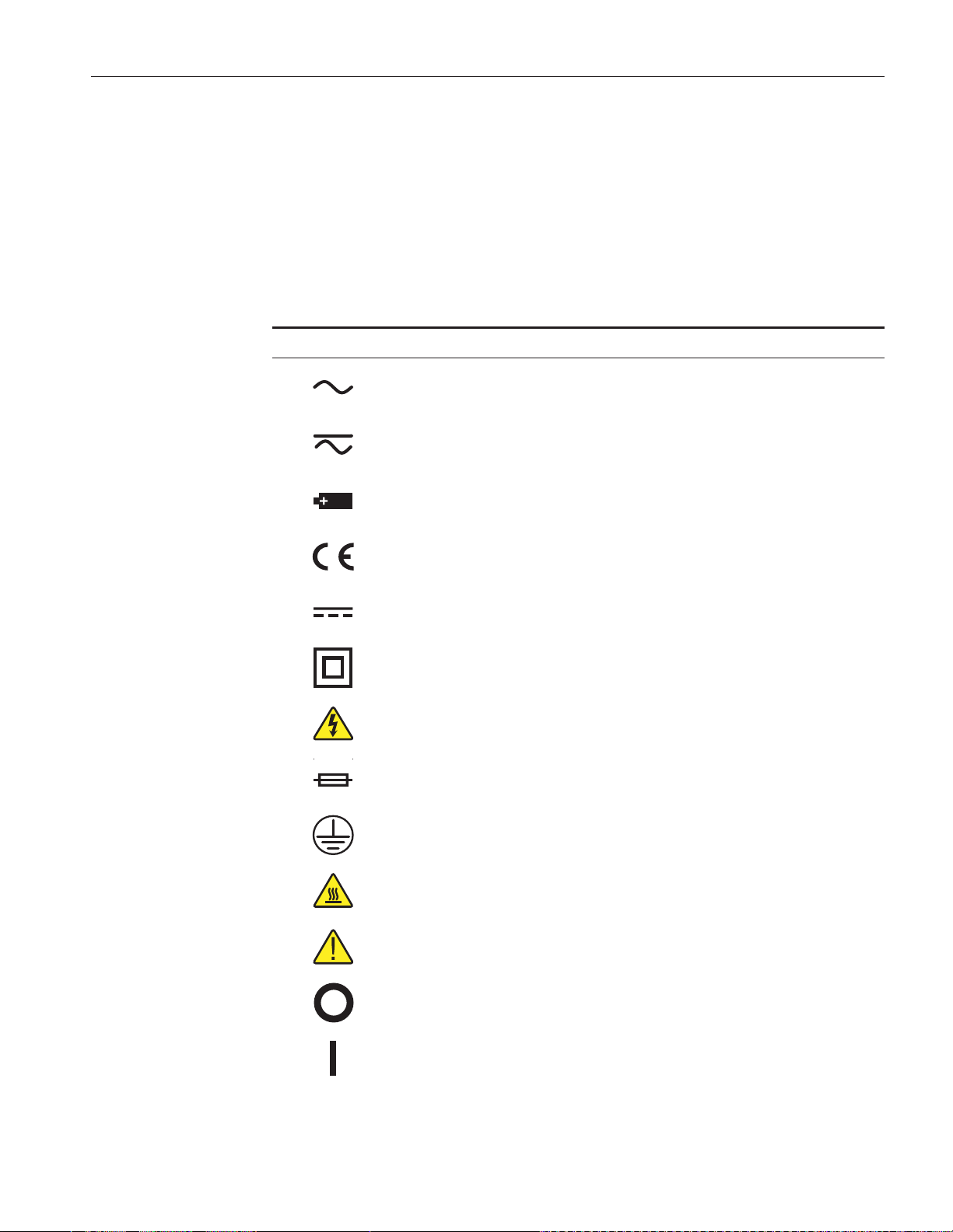
1.1 Symbols Used
Table 1 lists the International Electrical Symbols. Some or all of these symbols
may be used on the instrument or in this manual.
Table 1 International Electrical Symbols
Symbol Description
AC (Alternating Current)
AC-DC
Battery
1 Before You Start
Symbols Used
CE Complies with European Union Directives
DC
Double Insulated
Electric Shock
Fuse
PE Ground
Hot Surface (Burn Hazard)
Read the User’s Manual (Important Information)
Off
On
1
Page 9
9009 Industrial Dual-Block Calibrator
User’s Guide
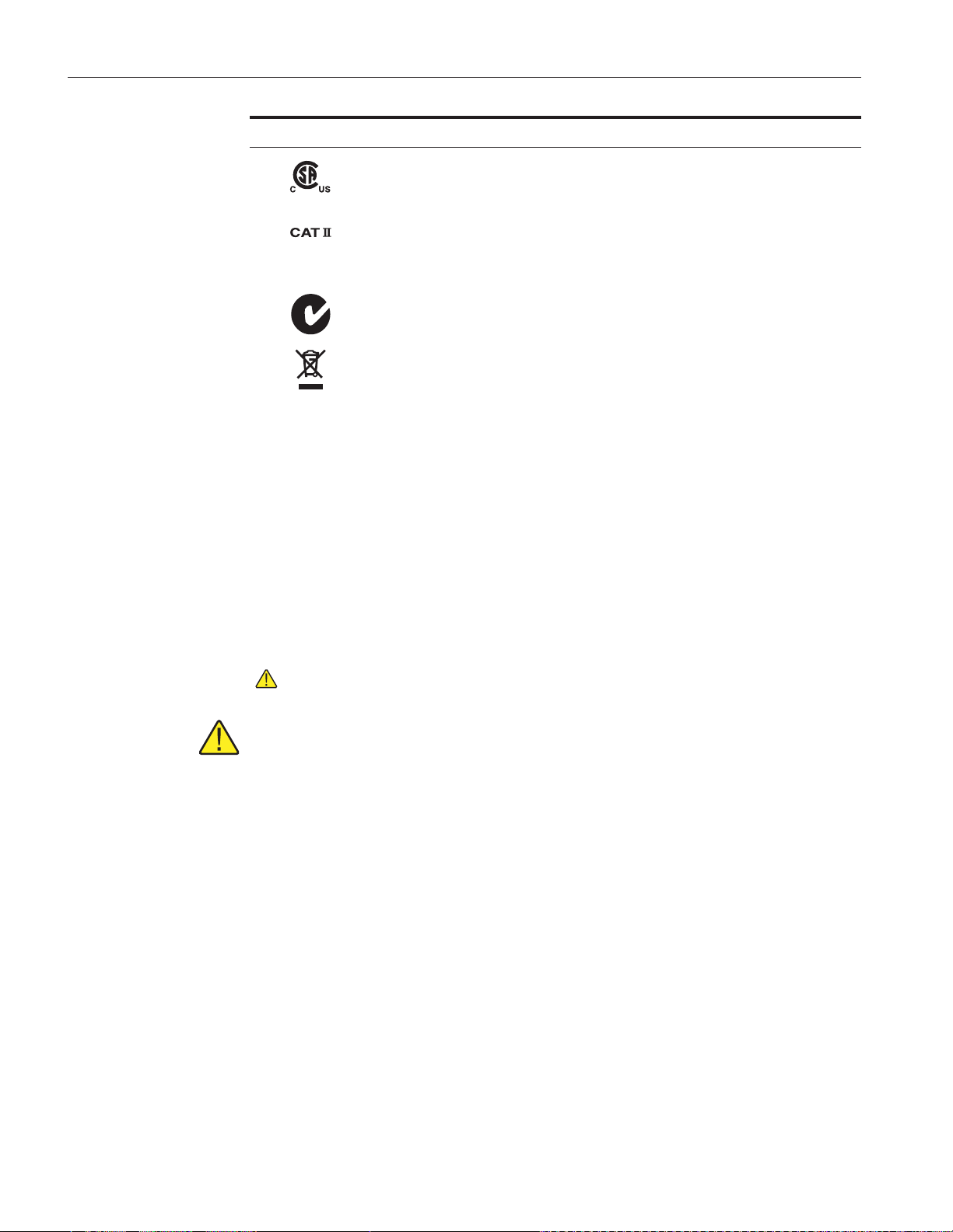
Symbol Description
Canadian Standards Association
OVERVOLTAGE (Installation) CATEGORY II, Pollution Degree 2 per IEC1010-1 re
fers to the level of Impulse Withstand Voltage protection provided. Equipment of
OVERVOLTAGE CATEGORY II is energy-consuming equipment to be supplied from
the fixed installation. Examples include household, office, and laboratory appliances.
C-TIC Australian EMC Mark
The European Waste Electrical and Electronic Equipment (WEEE) Directive
(2002/96/EC) mark.
1.2 Safety Information
Use this instrument only as specified in this manual. Otherwise, the protection
provided by the instrument may be impaired.
The following definitions apply to the terms “Warning” and “Caution”.
• “WARNING” identifies conditions and actions that may pose hazards to
the user.
• “CAUTION” identifies conditions and actions that may damage the in-
strument being used.
-
1.2.1
WARNINGS
DISCLAIMER: Hart Scientific manufactures instruments for the purpose
of temperature calibration. Instruments used for applications other than
calibration are used at the discretion and sole responsibility of the customer. Hart Scientific cannot accept any responsibility for the use of in
struments for any application other than temperature calibration.
GENERAL
DO NOT use the instrument for any application other than calibration work.
The instrument was designed for temperature calibration. Any other use of the
unit may cause unknown hazards to the user.
DO NOT use the unit in environments other than those listed in the user’s
guide.
Completely unattended operation in not recommended.
Follow all safety guidelines listed in the user’s manual.
Calibration Equipment should only be used by Trained Personnel.
-
2
Page 10

1 Before You Start
Safety Information
If this equipment is used in a manner not specified by the manufacturer, the
protection provided by the equipment may be impaired or safety hazards may
arise.
Inspect the instrument for damage before each use. DO NOT use the instru
-
ment if it appears damaged or operates abnormally.
Before initial use, or after transport, or after storage in humid or semi-humid
environments, or anytime the instrument has not been energized for more than
10 days, the instrument needs to be energized for a “dry-out” period of 2 hours
before it can be assumed to meet all of the safety requirements of the IEC
1010-1. If the product is wet or has been in a wet environment, take necessary
measures to remove moisture prior to applying power such as storage in a low
humidity temperature chamber operating at 50°C for 4 hours or more.
The instrument is intended for indoor use only.
The instrument has a built-in carrying case. Ensure the carrying case in closed
securely and the latches are securely in place when lifting the instrument. Lift
the instrument by the handle provided to move the instrument. DO NOT close
the case and move the instrument until the display reads less than 100°C
(212°F).
BURN HAZARD
ALWAYS ensure the instrument is COOL before closing the instrument for
storage.
DO NOT touch the well access surface of the unit.
• The temperature of the well access is the same as the actual temperature
shown on the display, e.g. if the unit is set at 350°C and the display reads
350°C, the well is at 350°C.
• Ensure the power cord is positioned in such a way as it cannot contact hot
surfaces or temperature probes. Always inspect power cord before use for
any damage to the insulation due to contact with hot surfaces, cuts or
abrasions.
•
The top sheet metal of the instrument may exhibit extreme temperatures
for areas close to the well access.
•
DO NOT turn off the unit at temperatures higher than 100°C. This could
create a hazardous situation. Select a set-point less that 100°C and allow
the unit to cool before turning it off.
•
DO NOT remove inserts at high temperatures. Inserts will be the same
temperature as the display temperature. Use extreme care when removing
hot inserts,
DO NOT operate near flammable materials. Extreme temperatures could ignite
the flammable material.
Use of this instrument at HIGH TEMPERATURES for extended periods of
time requires caution.
3
Page 11

9009 Industrial Dual-Block Calibrator
User’s Guide
ELECTRICAL HAZARD
These guidelines must be followed to ensure that the safety mechanisms in this
instrument will operate properly. This instrument must be plugged into a 115
VAC (± 10%) or 230 VAC (± 10%) 50/60 Hz only electric outlet as indicated
on the serial label. The power cord of the instrument is equipped with a
three-pronged grounding plug for your protection against electrical shock haz
ards. It must be plugged directly into a properly grounded three-prong recepta
cle. The receptacle must be installed in accordance with local codes and
ordinances or adapter plug. DO NOT use an extension cord Consult a qualified
electrician. Always inspect the power cord before use for any damage to the in
sulation due to contact with hot surfaces, cuts or abrasions.
The instrument is equipped with operator accessible fuses. If a fuse blows, it
may be due to a power surge or failure of a component. Replace the fuse once.
If the fuse blows a second time, it is likely caused by failure of a component
part. If this occurs, contact a Hart Scientific Authorized Service Center. Always
replace the fuse with one of the same rating, voltage, and type. Never replace
the fuse with one of a higher current rating.
-
-
-
1.2.2
Always replace the power cord with an approved cord of the correct rating and
type. If you have questions, contact a Hart Scientific Authorized Service Center
(see Section 1.3).
High voltage is used in the operation of this equipment. Severe injury or death
may result if personnel fail to observe the safety precautions.
The block vent cover may be hot due to the fan blowing upward.
CAUTIONS
Always operate this instrument at room temperatures as specified in Section
3.2, Environmental Conditions. Allow sufficient air circulation by leaving at
least 6 inches (15 cm) of clearance around the instrument.
Overhead clearance is required. DO NOT place this instrument under a cabinet
or other structure.
DO NOT use fluids to clean out the well. Fluids could leak into and damage
the instrument.
Never introduce any foreign material into the probe hole of the insert. Fluids,
etc. can leak into the instrument causing damage.
DO NOT change the values of the calibration constants from the factory set
values. The correct setting of these parameters is important to the safety and
proper operation of the unit.
DO NOT slam the probe stems into the well. This type of action can cause a
shock to the sensor and affect the calibration.
DO use a ground fault interrupt device.
4
Page 12

1 Before You Start
Authorized Service Centers
DO NOT operate this instrument in an excessively wet, oily, dusty, or dirty
environment.
The unit is a precision instrument. Although it has been designed for optimum
durability and trouble free operation, it must be handled with care.
Most probes have handle temperature limits. Be sure that the probe handle tem
perature limit is not exceeded in the air above the instrument.
The instrument and any thermometer probes used with it are sensitive instru
ments that can be easily damaged. Always handle these devices with care. Do
not allow them to be dropped, struck, stressed, or overheated.
When calibrating PRTs always follow correct calibration procedure and cali
brate from high temperatures to low temperatures with the appropriate triple
point of water checks.
Components and heater lifetimes can be shortened by continuous high tempera
ture operation.
If a mains supply power fluctuation occurs, immediately turn off the furnace.
Power bumps from brown-outs and black-outs can damage the instrument. Wait
until the power has stabilized before re-energizing the furnace.
The probe and the block may expand at different rates. Allow for probe expansion inside the well as the block heats. Otherwise, the probe may become stuck
in the well.
1.3 Authorized Service Centers
-
-
-
-
Please contact one of the following authorized Service Centers to coordinate
service on your Hart product:
Fluke Corporation, Hart Scientific Division
799 E. Utah Valley Drive
American Fork, UT 84003-9775
USA
Phone: +1.801.763.1600
Telefax: +1.801.763.1010
E-mail: support@hartscientific.com
Fluke Nederland B.V.
Customer Support Services
Science Park Eindhoven 5108
5692 EC Son
NETHERLANDS
5
Page 13

9009 Industrial Dual-Block Calibrator
User’s Guide
Phone: +31-402-675300
Telefax: +31-402-675321
E-mail: ServiceDesk@fluke.nl
Fluke Int'l Corporation
Service Center - Instrimpex
Room 2301 Sciteck Tower
22 Jianguomenwai Dajie
Chao Yang District
Beijing 100004, PRC
CHINA
Phone: +86-10-6-512-3436
Telefax: +86-10-6-512-3437
E-mail: xingye.han@fluke.com.cn
Fluke South East Asia Pte Ltd.
Fluke ASEAN Regional Office
Service Center
60 Alexandra Terrace #03-16
The Comtech (Lobby D)
118502
SINGAPORE
Phone: +65 6799-5588
Telefax: +65 6799-5588
E-mail: antng@singa.fluke.com
When contacting these Service Centers for support, please have the following
information available:
•
Model Number
•
Serial Number
•
Voltage
•
Complete description of the problem
6
Page 14

2 Introduction
The Hart Scientific 9009 Industrial Dual-Block Calibrator may be used as a
portable instrument or bench top temperature calibrator for calibrating thermo
couple and RTD temperature probes. The 9009 is small enough to use in the
field, and accurate enough to use in the lab. Calibrations may be done over a
range of –15°C to 350°C (5°F to 622°F). Temperature display resolution of the
9009 is 0.1 degrees.
The dry-well calibrator features:
Two independently controlled temperature blocks
•
Rapid heating and cooling
•
Interchangeable multiple hole probe sleeves
•
Convenient integrated carrying case
•
• RS-232 interface
2 Introduction
-
Built in programmable features include (applicable to both the hot and cold
blocks):
• Temperature scan rate control
• Eight set-point memory
• Adjustable readout in °C or °F
The temperature of each well is accurately controlled by a precision Hart Scientific controller. The controller uses a precision platinum RTD as a sensor and
controls the hot temperature block with a solid state relay (triac) driven heater.
A thermal electric device (TED) controls the cold temperature block.
The LED front panel continuously shows the current well temperature. The
temperature may be easily set with the control buttons to any desired tempera
ture within the specified range. The calibrator’s multiple fault protection de
vices insure user and instrument safety and protection.
Note: When one of the temperature blocks is being accessed through the front
panel, the other temperature block control panel is not accessible. Always press
the “EXIT” button to exit the control panel being used.
The 9009 calibrator was designed for portability, low cost, and ease of opera
tion. Through proper use, the instrument will provide continued accurate cali
bration of temperature sensors and devices. The user should be familiar with
the safety guidelines and operating procedures of the calibrator as described in
the instruction manual.
-
-
-
-
7
Page 15

3 Specifications and Environmental Conditions
3 Specifications and Environmental
Conditions
3.1 Specifications
Specification Hot Block Cold Block
Specifications
Range
Accuracy (Ambient at 23°C
±5°C)
Stability
Well-to-Well Uniformity
Display Resolution
Heating Times
Cooling Times
Stabilization Times
Well Depth
Removable Inserts
Power
Heater
Cooling
Size
†
‡
‡
50°C to 350°C (122°F to 662°F) –15°C to 110°C (5°F to 230°F)
[–8°C (17°F) to 110°C (230°F) when
hot block is at 350°C(662°F)]
±0.6°C ±0.2°C
±0.1°C from 50°C to 100°C
±0.05°C > 100°C
±0.1°C
0.1°
30 minutes from 25°C to 350°C 15 minutes from 25°C to 110°C
40 minutes from 350°C to 100°C 16 minutes from 25°C to -15°C
8 minutes
4 inches(102 mm)
Two 1/4”(6.4mm) and 3/16”(4.8mm)inserts included – other inserts available
115 VAC (±10%), 50/60 Hz, 3 A, 250 W
[optionally 230 VAC (±10%), 50/60 Hz, 1.6 A, 250 W]
135 W 40 W TED
Fan 40 W TED
7”H x 10.5”W x 9.75”D (178 x 267 x 248 mm)
±0.05°C
Weight
Safety
†
Stability is two times the standard deviation.
‡
Heating and cooling times may be affected by line voltages and ambient temperatures.
OVER VOLTAGE (Installation) CATEGORY II, Pollution Degree 2 per
3.2 Environmental Conditions
Although the instrument has been designed for optimum durability and trou
ble-free operation, it must be handled with care. The instrument should not be
operated in an excessively dusty or dirty environment. Maintenance and clean
ing recommendations can be found in the Maintenance Section of this manual.
The instrument operates safely under the following conditions:
•
ambient temperature range: 5 - 45°C (41 - 113°F)
10 lb (4.5 kg)
IEC1010-1
-
-
9
Page 16

9009 Industrial Dual-Block Calibrator
User’s Guide
ambient relative humidity: maximum 80% for temperature <31°C, de
•
creasing linearly to 50% at 40°C
pressure: 75kPa - 106kPa
•
mains voltage within ± 10% of nominal
•
vibrations in the calibration environment should be minimized
•
altitudes less than 2,000 meters
•
indoor use only
•
-
10
Page 17

4 Quick Start
4.1 Unpacking
4 Quick Start
Unpacking
Unpack the calibrator carefully and inspect it for any damage that may have oc
curred during shipment. If there is shipping damage, notify the carrier
immediately.
Verify that the following components are present:
9009 Dry-well
•
Two 3102-3 ( 3/16”) and two 3102-4 (1/4”) Inserts
•
Power Cord
•
Report of Calibration with calibration label
•
• User’s Guide
• 9930 Interface-it Software and User’s Guide
• RS-232 Cable
• Insert Removal Tool
4.2 Set-Up
Place the calibrator on a flat surface with at least 18 inches above the instrument. Plug the power cord into a grounded mains outlet. Observe that the nominal voltage corresponds to that indicated on the calibrator.
-
Carefully insert the probe sleeves into the wells. (DO NOT drop the sleeve in
the well.) Probe sleeve holes should be of the smallest diameter possible while
still allowing the probe to slide in and out easily. Sleeves with various hole
sizes are available from Hart Scientific. The well must be clear of any foreign
objects, dirt and grit before the sleeve is inserted. The sleeve is inserted with
the small tong hole positioned upward.
Turn on the power to the calibrator by toggling the switch on the power entry
module. The fan should begin quietly blowing air through the instrument and
the controller displays should illuminate after 3 seconds. After a brief self test
the controller should begin normal operation. If the unit fails to operate please
check the power connection.
The displays will begin to show the well temperature and the well heater and
TEDs will start operating to bring the temperature of the wells to the set-point
temperatures.
4.3 Power
Plug the calibrator power cord into a mains outlet of the proper voltage, fre
quency, and current capability. Refer to Section 3.1, Specifications, for power
-
11
Page 18

9009 Industrial Dual-Block Calibrator
User’s Guide
requirements. Turn the calibrator on using the “POWER” switch on the power
entry module (PEM). The calibrator will turn on and begin to heat or cool to
the previously programmed temperature set-point. The front panel LED dis
plays will indicate the actual calibrator temperature.
4.4 Setting the Temperature
-
Section 7.2 explains in detail how to set the temperature set-point on the cali
brator using the front panel keys. The procedure is summarized here.
(1) Press “SET” twice to access the set-point value.
(2) Press “UP” or “DOWN” to change the set-point value.
(3) Press “SET” to store the new set-point.
(4) Press “EXIT” to return to the temperature display.
When the set-point temperature is changed the controller will switch the well
heater on or off to raise or lower the temperature. The displayed well temperature will gradually change until it reaches the set-point temperature. The well
may require 5 to 10 minutes to reach the set-point depending on the span. Another 5 to 10 minutes is required to stabilize within ±0.1°C of the set-point. Ultimate stability may take 15 to 20 minutes more of stabilization time.
4.5 Changing Display Units
The 9009 can display temperature in Celsius or Fahrenheit. The instrument is
shipped from the factory set to Celsius. To change to Fahrenheit or back to Celsius perform the following:
-
12
1. Press the “SET” and “UP” button simultaneously. The temperature displays
the converted temperature and units.
Or
1. Press the “SET” button three times.
2. Press the “UP” or “DOWN” buttons to change the units.
3. Press the “SET” button to store the change.
Page 19

5 Parts and Controls
The user should become familiar with the dry-well calibrator and its parts.
5.1 Top Panel (Lid Open)
5 Parts and Controls
Top Panel (Lid Open)
Figure 1 Top Panel (Lid Open)
Power Switch - The power switch is located on the power entry module
(PEM). The PEM also houses the fuse.
Power Cord - The removable power cord inlet plugs into an IEC grounded
socket on the PEM.
Insert Storage - Four inserts may be stored here.
Constant Temperature Block Assembly - Calibrate two sensors at once or use
one well for a reference thermometer. See Section 5.2 for additional details.
13
Page 20

9009 Industrial Dual-Block Calibrator
User’s Guide
Serial Port - A three-conductor jack is present for interfacing the calibrator to
a computer or terminal with serial RS-232 communications.
Controller Display - The digital display is an important part of the temperature
controller because it not only displays set and actual temperatures but also vari
ous calibrator functions, settings, and constants. The display shows tempera
tures in units according to the selected scale °C or °F. The High Temp and Low
Temp displays are labeled.
Controller Keypad - The four button keypad allows easy setting of the
set-point temperature. The control buttons (SET, DOWN, UP, and EXIT) are
used to set the calibrator temperature set-point, access and set other operating
parameters, and access and set calibration parameters. The High Temp and Low
Temp controllers each have their own set of buttons.
Setting the control temperature is done directly in degrees of the current scale.
It can be set to one-tenth of a degree Celsius or Fahrenheit.
The functions of the buttons are as follows:
-
-
SET – Used to display the next parameter in the menu and to store parameters
to the displayed value.
DOWN – Used to decrement the displayed value of parameters.
UP–Usedtoincrementthedisplayedvalue.
EXIT – Used to exit a function and skip to the next function. Any changes
made to the displayed value are ignored.
5.2 Constant Temperature Block Assembly
5.2.1 Constant Temperature Block
The high temperature “Block” is made of bronze and the cold temperature
“Block” is made of aluminum. The “Block” provides a constant and accurate
temperature environment for the sensor that is to be calibrated (see Figure 2). A
0.5” diameter well is provided that may be used for sensors of that size or may
be sleeved down with various sized probe sleeves. Heaters are strategically
placed in the block assembly to provide even heat to the sensor. A high-temper
ature platinum control RTD is imbedded at the base of the block assembly to
sense and control the temperature of the block. The entire assembly is sus
pended in an air cooled chamber thermally isolated from the chassis and
electronics.
-
-
14
WARNING: The block vent cover may be very hot due to the fan blowing
upward.
Page 21

5.3 Accessories
The following inserts are available for the 9009 calibrator. Inserts may be used
with either the hot or cold temperature wells.
5 Parts and Controls
Accessories
Figure 2 Constant Temperature Block
Assembly
Model Description
3102-0 Blank Insert
3102-1 1/16” (1.6 mm) Insert
3102-2 1/8” (3.2 mm) Insert
3102-3 3/16” (4.8 mm) Insert
3102-4 1/4” (6.4 mm) Insert
3102-5 5/16” (7.9 mm) Insert
3102-6 3/8” (9.5 mm) Insert
3102-7 7/16” (11.1 mm) Insert
3102-8 5/32” (4.0 mm) Insert
15
Page 22

6 General Operation
6.1 Changing Display Units
The 9009 can display temperature in Celsius or Fahrenheit. The temperature
units are shipped from the factory set to Celsius. To change to Fahrenheit or
back to Celsius there are two ways:
1-Press the “SET” and “UP” simultaneously. This will change display units.
Or
1-Press the “SET” button three times from the temperature display to show
Un= C
2-Press the “UP” or “DOWN” button to change units.
3-Press “SET” to store changes.
6 General Operation
Changing Display Units
17
Page 23

7 Controller Operation
7 Controller Operation
Well Temperature
This chapter discusses in detail how to operate the calibrator temperature con
troller using the front control panel. Using the front panel key-switches and
LED display the user may monitor the well temperature, set the temperature
set-point in degrees C or F, monitor the heater output power, adjust the control
ler proportional band, and program the calibration parameters, operating pa
rameters, and serial interface configuration. Operation of the functions and
parameters are shown in the flowchart in Figure 3 on page 20. This chart may
be copied for reference.
In the following discussion a button with the word SET, UP, EXIT or DOWN
inside indicates the panel button while the dotted box indicates the display
reading. Explanation of the button or display reading are to the right of each
button or display value.
Note: When using one set of control buttons, the other set is disabled.
7.1 Well Temperature
The digital LED display on the front panel allows direct viewing of the actual
well temperature. This temperature value is what is normally shown on the display. The units, C or F, of the temperature value are displayed at the right. For
example,
-
-
-
100.0 C
The temperature display function may be accessed from any other function by
pressing and holding the “EXIT” button.
Well temperature in degrees Celsius
7.2 Temperature Set-point
The temperature set-point can be set to any value within the range and resolu
tion as given in the specifications. Be careful not to exceed the safe upper tem
perature limit of any device inserted into the well.
Setting the temperature involves two steps: (1) selecting the set-point memory
and (2) adjusting the set-point value.
7.2.1 Programmable Set-points
The controller stores 8 set-point temperatures in memory. The set-points can be
quickly recalled to conveniently set the calibrator to a previously programmed
temperature set-point.
To set the temperature one must first select the set-point memory. This function
is accessed from the temperature display function by pressing “SET”. The
number of the set-point memory currently being used is shown at the left on the
display followed by the current set-point value.
-
-
19
Page 24

9009 Industrial Dual-Block Calibrator
User’s Guide
Figure 3 Controller Operation Flowchart
20
Page 25

7 Controller Operation
Temperature Set-point
100.0 C
S
Access set-point memory
1 100.
To change to another set-point memory press “UP” or “DOWN”.
4 300.
Press “SET” to accept the new selection and access the set-point value.
S
Accept selected set-point memory
7.2.2 Set-point Value
The set-point value may be adjusted after selecting the set-point memory and
pressing “SET”.
Well temperature in degrees Celsius
Set-point memory 1, 100°C currently used
New set-point memory 4, 300°C
4 200.
If the set-point value is correct then press “EXIT” to resume displaying the well
temperature. To change the set-point values, press “SET” and then press “UP”
or “DOWN” to adjust the set-point value.
220.00
When the desired set-point value is reached press “SET” to accept the new
value and access the temperature scale units selection. If “EXIT” is pressed instead then any changes made to the set-point will be ignored.
S
Accept new set-point value
Set-point 4 value in°C
New set-point value
7.2.3 Temperature Scale Units
The temperature scale units of the controller maybe set by the user to degrees
Celsius (°C) or Fahrenheit (°F). The units are used in displaying the well tem
perature, set-point, and proportional band.
Press “SET” after adjusting the set-point value to change display units.
-
Un= C Scale units currently selected
Press “UP” or “DOWN” to change the units.
21
Page 26

9009 Industrial Dual-Block Calibrator
User’s Guide
Un= F New units selected
Press “SET” to accept the present setting and to continue.
7.3 Scan
The scan rate can be set and enabled so that when the set-point is changed the
calibrator heats or cools at a specified rate (degrees per minute) until it reaches
the new set-point. With the scan disabled the calibrator heats or cools at the
maximum possible rate.
7.3.1 Scan Control
The scan is controlled with the scan on/off function that appears in the main
menu after the temperature scale units.
Sc=OFF
Press “UP” or “DOWN” to toggle the scan on or off.
Sc=On
Press “SET” to accept the present setting and to continue.
S
Accept scan setting
7.3.2 Scan Rate
The next function in the main menu is the scan rate. The scan rate can be set
from .1 to 99.9°C/min. The maximum scan rate however is actually limited by
the natural heating or cooling rate of the instrument. This is often less than
100°C/min, especially when cooling.
The scan rate function appears in the main menu after the scan control function.
The scan rate units are in degrees per minute, degrees C or F depending on the
selected units.
Sr= 10.0
Scan function off
Scan function on
Scan rate in°C/min
22
Press“UP”or“DOWN”tochangethescanrate.
Sr= 2.0
Press “SET” to accept the new scan rate and continue.
S
Accept scan rate
New scan rate
Page 27

7.4 Secondary Menu
Functions which are used less often are accessed within the secondary menu.
The secondary menu is accessed by pressing “SET” and “EXIT” simulta
neously and then releasing. The first function in the secondary menu is the
heater power display. (See Figure 3 on page 20.)
7.5 Heater Power
The temperature controller controls the temperature of the well by pulsing the
heater on and off. The total power being applied to the heater is determined by
the duty cycle or the ratio of heater on time to the pulse cycle time. By knowing
the amount of heating the user can tell if the calibrator is heating up to the
set-point, cooling down, or controlling at a constant temperature. Monitoring
the percent heater power will let the user know how stable the well temperature
is. With good control stability the percent heating power should not fluctuate
more than ±1% within one minute.
7 Controller Operation
Secondary Menu
-
Note: For the Cold Side, negative numbers indicate the well is being cooled.
When the display reads, –100 P, the well is being cooled at maximum power.
When the display reads, 0 P, the well is neither heating nor cooling. When the
display reads, 100 P, the well is being heated at maximum power.
For the hot side, when the display reads, 0 P, maximum cooling is occurring
(no heater power is applied). The power percentage is never negative on the hot
side.
The heater power display is accessed in the secondary menu. Press “SET” and
“EXIT” simultaneously and release. The heater power will be displayed as a
percentage of full power.
100.0 C
S+E
Well temperature
Access heater power in secondary menu
SEC Flashes for secondary menu and then displays the
heater power
13.0 P
Heater power in percent
To exit out of the secondary menu press and hold “EXIT”. To continue on to
the proportional band setting function press “SET”.
7.6 Proportional Band
In a proportional controller such as this the heater output power is proportional
to the well temperature over a limited range of temperatures around the
23
Page 28

9009 Industrial Dual-Block Calibrator
User’s Guide
set-point. This range of temperature is called the proportional band. At the bot
tom of the proportional band the heater output is 100%. At the top of the pro
portional band the heater output is 0. Thus as the temperature rises the heater
power is reduced, which consequently tends to lower the temperature back
down. In this way the temperature is maintained at a fairly constant
temperature.
The temperature stability of the well and response time depend on the width of
the proportional band. If the band is too wide the well temperature deviates ex
cessively from the set-point due to varying external conditions. This is because
the power output changes very little with temperature and the controller cannot
respond very well to changing conditions or noise in the system. If the propor
tional band is too narrow the temperature may swing back and forth because
the controller overreacts to temperature variations. For best control stability the
proportional band must be set for the optimum width.
The proportional band width is set at the factory. The proportional band width
may be altered by the user if he desires to optimize the control characteristics
for a particular application.
The proportional band width is easily adjusted from the front panel. The width
may be set to discrete values in degrees C or F depending on the selected units.
The proportional band adjustment is accessed within the secondary menu. Press
“SET” and “EXIT” to enter the secondary menu and show the heater power.
Then press “SET” to access the proportional band.
-
-
-
-
S+E
Access heater power in secondary menu
SEC Flashes for secondary menu and then displays the
heater power
Heater power in percent
S
13.0 P
Access proportional band
ProP Flashes and then displays the current setting
4.1 Current proportional band setting
To change the proportional band press “UP” or “DOWN”.
10.0
To accept the new setting press “SET”. Press “EXIT” to continue without stor
ing the new value.
New proportional band setting
-
24
Page 29

7 Controller Operation
Controller Configuration
S
Accept the new proportional band setting
7.7 Controller Configuration
The controller has a number of configuration and operating options and calibra
tion parameters which are programmable via the front panel. These are ac
cessed from the secondary menu after the proportional band function by
pressing “SET”. The display flashes “COnFIG” and then displays “Par”for
the first of three sets of configuration parameters — operating parameters, se
rial interface parameters, and calibration parameters. The sets are selected us
ing the “UP” and “DOWN” keys and then pressing “SET” (see Figure 3 on
page 20).
7.8 Operating Parameters
The operating parameters menu is indicated by,
PAr
Press “SET” to enter the menu. The operating parameters menu contains the
HL (High Limit) parameter. The HL parameter adjusts the upper set-point temperature. The factory default and maximum are set to 350°C. For safety, a user
can adjust the HL down so the maximum temperature set-point is restricted.
Operating parameters menu
-
-
-
-
HL
H=350
Adjust the HL parameter using “UP” or “DOWN”.
H=300
Press “SET” to accept the new temperature limit.
Flashes HL and then displays the current value
Current HL setting
New HL setting
7.9 Serial Interface Parameters
The serial RS-232 interface parameters menu is indicated by,
SErIAL
The serial interface parameters menu contains parameters which determine the
operation of the serial interface. These controls only apply to instruments fitted
with the serial interface. The parameters in the menu are — BAUD rate, sample
period, duplex mode, and linefeed. Press “SET” to enter the menu.
Serial RS-232 interface parameters menu
25
Page 30

9009 Industrial Dual-Block Calibrator
User’s Guide
7.9.1 BAUD Rate
The BAUD rate is the first parameter in the menu. The BAUD rate setting de
termines the serial communications transmission rate.
bAUd
2400 b
The BAUD rate of the serial communications may be programmed to 300, 600,
1200, 2400 (default), 4800, or 9600 BAUD. Use “UP” or “DOWN” to change
theBAUDratevalue.
4800 b
Press “SET” to set the BAUD rate to the new value or “EXIT” to abort the operation and skip to the next parameter in the menu.
7.9.2 Sample Period
The sample period is the next parameter in the serial interface parameter menu.
The sample period is the time period in seconds between temperature measurements transmitted from the serial interface. If the sample rate is set to 5, the instrument transmits the current measurement over the serial interface
approximately every five seconds. The automatic sampling is disabled with a
sample period of 0.
-
Flashes and then displays the current setting
Current BAUD rate setting
New BAUD rate
SPer
SP= 1
Adjust the value with “UP” or “DOWN” and then use “SET” to set the sample
rate to the displayed value.
SP= 60
7.9.3 Duplex Mode
The next parameter is the duplex mode. The duplex mode may be set to full du
plex or half duplex. With full duplex any commands received by the calibrator
via the serial interface are immediately echoed or transmitted back to the device
of origin. With half duplex the commands are executed but not echoed.
dUPL
d=FULL
Flashes and then displays the current setting
Current sample period (seconds) setting
New sample period
-
Flashes and then displays the current setting
Current duplex mode setting
26
Page 31

7 Controller Operation
Calibration Parameters
The mode may be changed using “UP” or “DOWN” and pressing “SET”.
d=HALF
New duplex mode setting
7.9.4 Linefeed
The final parameter in the serial interface menu is the linefeed mode. This pa
rameter enables (on) or disables (off) transmission of a linefeed character (LF,
ASCII 10) after transmission of any carriage-return.
LF
LF= On
The mode may be changed using “UP” or “DOWN” and pressing “SET”.
LF= OFF
Flashes and then displays the current setting
Current linefeed setting
New linefeed setting
7.10 Calibration Parameters
The operator of the instrument controller has access to a number of the calibration constants namely R0, ALPHA, DELTA, and BETA (cold side only). These
values are set at the factory and must not be altered. The correct values are important to the accuracy and proper and safe operation of the instrument. Access
to these parameters is available to the user so that in the event that the controller memory fails the user may restore these values to the factory settings. These
constants and their settings are on the Report of Calibration that is shipped with
the instrument.
-
CAUTION: DO NOT change the values of the instrument's calibration
constants from the factory set values. The correct setting of these parame
ters is important to the safety and proper operation of the instrument.
The calibration parameters menu is indicated by,
CAL
Press “SET” five times to enter the menu. The calibration parameters menu
contains the parameters, R0, ALPHA, DELTA, and BETA (cold side only)
which characterize the resistance-temperature relationship of the platinum con
trol sensor. These parameters may be adjusted to improve the accuracy of the
calibrator.
The calibration parameter name flashes on the display and then the current
value is displayed. The value of the parameter may be changed using the “UP”
and “DOWN” buttons. After the desired value is reached press “SET” to set the
Calibration parameters menu
-
27
-
Page 32

9009 Industrial Dual-Block Calibrator
User’s Guide
parameter to the new value. Pressing “EXIT” causes the parameter to be
skipped ignoring any changes that may have been made.
7.10.1 R0
This probe parameter refers to the resistance of the control probe at 0°C. The
value of this parameter is set at the factory for best instrument accuracy.
7.10.2 ALPHA
This probe parameter refers to the average sensitivity of the probe between 0
and 100°C. The value of this parameter is set at the factory for best instrument
accuracy.
7.10.3 DELTA
This probe parameter characterizes the curvature of the resistance-temperature
relationship of the sensor. The value of this parameter is set at the factory for
best instrument accuracy.
7.10.4 BETA (Low Temp Only)
This probe parameter characterizes the low temperatures. The value of this parameter is set at the factory for best instrument accuracy.
28
Page 33

8 Digital Communication Interface
8 Digital Communication Interface
The calibrator is capable of communicating with and being controlled by other
equipment through the digital serial interface.
With a digital interface the instrument may be connected to a computer or other
equipment. This allows the user to set the set-point temperature, monitor the
temperature, and access any of the other controller functions, all using remote
communications equipment. Communications commands are summarized in
Table 2 on page 32.
8.1 Serial Communications
Serial Communications
The calibrator is installed with an RS-232 serial interface that allows serial dig
ital communications over fairly long distances. With the serial interface the user
may access any of the functions, parameters and settings discussed in Section7
with the exception of the BAUD rate setting. The protocol for serial communications is eight data bits, one stop bit, no parity, and no flow control.
8.1.1 Wiring
The three-conductor jack for the serial port is located on the top of the instrument. Figure 4 shows the pin-out of this connector. Note: The TxD line on one
side connects to the RxD line on the other and vice-versa. To reduce the possibility of electrical interference, the serial cable should be shielded with low resistance between the connector and the shield.
-
GND
RxD
TxD
Figure 4 Serial Cable Wiring
GND
TxD
RxD
5
9
4
8
3
7
2
6
1
29
Page 34

9009 Industrial Dual-Block Calibrator
User’s Guide
8.1.2 Setup
Before operation the serial interface must first be set up by programming the
BAUD rate and other configuration parameters. These parameters are pro
grammed within the serial interface menu. The serial interface parameters
menu is outlined in Figure 3 on page 20.
To enter the serial parameter programming mode first press “EXIT” while
pressing “SET” and release to enter the secondary menu. Press “SET” until the
display reads “Par”. Press “UP” until the serial interface menu is indicated
with “SErIAL”. Finally press “SET” to enter the serial parameter menu. In the
serial interface parameters menu are the BAUD rate, the sample rate, the duplex
mode, and the linefeed parameter.
8.1.2.1 Baud Rate
The baud rate is the first parameter in the menu. The display will prompt with
the baud rate parameter by showing “bAUd”. The current baud rate value is
displayed. The baud rate of the 9009 serial communications may be programmed to 300, 600, 1200, 2400, 4800, or 9600 baud. The baud rate is
pre-programmed to 2400 baud. Use “UP” or “DOWN” to change the BAUD
rate value. Press “SET” to set the BAUD rate to the new value or “EXIT” to
abort the operation and skip to the next parameter in the menu.
-
8.1.2.2 Sample Period
The sample period is the next parameter in the menu and prompted with
“SPEr”. The sample period is the time period in seconds between temperature
measurements transmitted from the serial interface. If the sample rate is set to 5
then the instrument transmits the current measurement over the serial interface
approximately every five seconds. The automatic sampling is disabled with a
sample period of 0. Adjust the period with “UP” or “DOWN” and then use
“SET” to set the sample rate to the displayed value.
8.1.2.3 Duplex Mode
The next parameter is the duplex mode indicated with “dUPL”. The duplex
mode may be set to half duplex (“HALF”) or full duplex (“FULL”). With full
duplex any commands received by the thermometer via the serial interface are
immediately echoed or transmitted back to the device of origin. With half du
plex the commands are executed but not echoed. The default setting is full du
plex. The mode may be changed using “UP” or “DOWN” and pressing “SET”.
8.1.2.4 Linefeed
The final parameter in the serial interface menu is the linefeed mode. This pa
rameter enables (“On”) or disables (“OFF”) transmission of a linefeed charac
ter (LF, ASCII 10) after transmission of any carriage-return. The default setting
is with linefeed on. The mode may be changed using “UP” or “DOWN” and
pressing “SET”.
-
-
-
-
30
Page 35

8.1.3 Serial Operation
8 Digital Communication Interface
Interface Commands
Once the cable has been attached and the interface set up properly the control
ler immediately begins transmitting temperature readings at the programmed
rate. The serial communications uses 8 data bits, one stop bit, and no parity.
The set-point and other commands may be sent via the serial interface to set the
temperature set-point and view or program the various parameters. The inter
face commands are discussed in Section 8.2. All commands are ASCII charac
ter strings terminated with a carriage-return character (CR, ASCII 13).
8.2 Interface Commands
NOTE: When sending a command, preface the command with either a C:
(cold side) or H: (hot side). If the C: or H: are left off, the returned value
is for the hot side.
The various commands for accessing the calibrator functions via the digital in
terfaces are listed in this section (see Table 2). These commands are used with
the RS-232 serial interface. The commands are terminated with a carriage-return character. The interface makes no distinction between upper and lower
case letters, hence either may be used. Commands may be abbreviated to the
minimum number of letters which determines a unique command. A command
may be used to either set a parameter or display a parameter depending on
whether or not a value is sent with the command following a “=” character. For
example “s”<CR> returns the current set-point and “s=150.0”<CR> sets the
set-point to 150.0 degrees.
-
-
-
-
In the following list of commands, characters or data within brackets, “[” and
“]”, are optional for the command. A slash, “/”, denotes alternate characters or
data. Numeric data, denoted by “n”, may be entered in decimal or exponential
notation. Characters are shown in lower case although upper case may be used.
Spaces may be added within command strings and will simply be ignored.
Backspace (BS, ASCII 8) may be used to erase the previous character. A termi
nating CR is implied with all commands.
-
31
Page 36

9009 Industrial Dual-Block Calibrator
User’s Guide
Table 2 9009 Controller Communications Commands
Command Description
Command
†
Format
Command
Example
‡
Returned
Returned
Example
Acceptable
Values
Display Temperature
Read current set-point s[etpoint] s set: 9999.99 {C or F} set: 150.00 C
Set current set-point to n s[etpoint]=n s=350 Instrument
Range
Read temperature t[emperature] t t{h or c}: 9999.99 {C orF}th: 55.66 C
Read temperature units u[nits] u u: x u: C
Set temperature units: u[nits]=c/f
CorF
Set temperature units to Celsius u[nits]=c u=c
Set temperature units to
u[nits]=f u=f
Fahrenheit
Read scan mode sc[an] sc sc: {ON or OFF} sc: ON
Set scan mode sc[an]=on/off sc=on ON or OFF
Read scan rate sr[ate] sr srat: 99.9 {C or F}/min srat:12.4 C/min
Set scan rate sr[ate]=n sr=1.1 0.1 to 99.9
Secondary Menu
Read proportional band setting pr[opband] pr pb: 999.9 pb: 15.9
Set proportional band to
Read heater power
n
pr[opband]=n pr=8.83 Depends on
po[wer] po po: 999.9 po: 1.3
(duty cycle)
Configuration Menu
Operating Parameters Menu
Read High Limit hl hl hl: 999 hl: 350
Set High Limit hl=
n
hl=350 Cold 25 to 126,
Serial Interface Menu
Read serial sample setting sa[mple] sa sa: 9 sa: 1
n
Set serial sampling setting to
sa[mple]=n sa=0 0 to 999
seconds
Set serial duplex mode: du[plex]=f[ull]/h[alf]
Set serial duplex mode to full du[plex]=f[ull] du=f
Set serial duplex mode to half du[plex]=h[alf] du=h
Set serial linefeed mode: lf[eed]=on/of[f]
Set serial linefeed mode to on lf[eed]=on lf=on
Set serial linefeed mode to off lf[eed]=of[f] lf=of
Configuration
Hot50to350
FULL or HALF
ON or OFF
32
Page 37

9009 Communication Commands Continued
8 Digital Communication Interface
Interface Commands
Command Description
Command
†
Format
Command
Example
‡
Returned
Returned
Example
Acceptable
Values
Calibration Parameters Menu
Read R0 calibration parameter r[0] r r0: 999.999 r0: 100.578
n
Set R0 calibration parameter to
Read ALPHA calibration
r[0]=n r=100.324 100 to 105
al[pha] al al: 9.9999999 al: 0.0038573
parameter
Set ALPHA calibration parameter
n
to
Read DELTA calibration
al[pha]=n al=0.0038433 0.002 to 0.006
de[lta] de de: 9.9999 de: 1.507
parameter
Set DELTA calibration parameter de[lta]=n de=1.3742 0.5 to 1.9
Read BETA calibration parameter be[ta] be Be: 9.999 be:0.342 —25 to 25
Set BETA calibration parameter be[ta]=n be=0.342
Miscellaneous
Read firmware version number *ver[sion] *ver ver.9999,9.99 ver.9009,1.21
Read structure of all commands h[elp] h list of commands
Read ALL operating parameters all all list of parameters
Legend: [] Optional Command data
{} Returns either information
n Numeric data supplied by user
9 Numeric data returned to user
x Character data returned to user
Note: When DUPLEX is set to FULL and a command is sent to READ, the command is returned followed by a
carriage return and linefeed. Then the value is returned as indicated in the RETURNED column.
†
Preface all commands with either C: (for cold side) or H: (for hot side). If the C: or H: is left off, the returned value is for the hot side.
‡
The returned command has either a ‘C’ or an ‘H’ before the colon depending on which side was queried.
33
Page 38

9 Test Probe Calibration
For optimum accuracy and stability, allow the calibrator to warm up for 10
minutes after power-up and then allow adequate stabilization time after reach
ing the set-point temperature. After completing operation of the calibrator, al
low the well to cool by setting the temperature to 25°C for one-half hour before
switching the power off.
9.1 Calibrating a Single Probe
Insert the probe to be calibrated into the well of the calibrator. The probe
should fit snugly into the calibrator probe sleeve yet should not be so tight that
it cannot be easily removed. Avoid any dirt or grit that may cause the probe to
jam into the sleeve. Best results are obtained with the probe inserted to the full
depth of the well. Once the probe is inserted into the well, allow adequate stabilization time to allow the test probe temperature to settle as described above.
Once the probe has settled to the temperature of the well, it may be compared
to the calibrator display temperature. The display temperature should be stable
to within 0.1°C degree for best results.
9 Test Probe Calibration
Calibrating a Single Probe
-
-
CAUTION: Never introduce any foreign material into the probe hole of
the insert. Fluids etc. can leak into the calibrator causing damage to the
calibrator or binding and damage to your probe.
9.2 Calibrator Characteristics
There is a temperature gradient vertically in the test well. The heater has been
applied to the block in such a way as to compensate for nominal heat losses out
of the top of the calibrator. However, actual heat losses will vary with design of
the thermometer probes inserted into the calibrator and the temperature. For
best results, insert probe to full depth of well.
9.2.1 Stabilization and Accuracy
The stabilization time of the calibrator depends on the conditions and tempera
tures involved. Typically the test well will stabalize to 0.1°C within 5 minutes
of reaching the set-point temperature as indicated by the display. Ultimate sta
bility is achieved 10 to 20 minutes after reaching the set temperature.
Inserting a cold probe into a well requires another period of stabilizing depend
ing on the magnitude of the disturbance and the required accuracy. For exam
ple, inserting a 0.25 inch diameter room temperature probe into a sleeve at
300°C takes 5 minutes to be within 0.1°C of its settled point and takes 10 min
utes to achieve maximum stability.
-
-
-
-
-
Speeding up the calibration process can be accomplished by knowing how soon
to make the measurement. It is recommended that typical measurements be
35
Page 39

9009 Industrial Dual-Block Calibrator
User’s Guide
made at the desired temperatures with the desired test probes to establish these
times.
36
Page 40

10 Calibration Procedure
10 Calibration Procedure
Calibration Points
Sometimes the user may want to calibrate the instrument to improve the tem
perature set-point accuracy. Calibration is done by adjusting the controller
probe calibration constants R0 , ALPHA, DELTA, and BETA (cold side) so that
the temperature of the calibrator as measured with a standard thermometer
agrees more closely with the set-point. The thermometer used must be able to
measure the well temperature with higher accuracy than the desired accuracy of
the calibrator. By using a good thermometer and following this procedure the
instrument can be calibrated to an accuracy of better than 0.5°C up 100°C.
10.1 Calibration Points
In calibrating the instrument, R0, ALPHA, DELTA, and BETA (cold side) are
adjusted to minimize the set-point error at each of three different temperatures.
Any three reasonably separated temperatures may be used for the calibration.
Improved results can be obtained for shorter ranges when using temperatures
that are just within the most useful operating range of the instrument. The farther apart the calibration temperatures, the larger will be the calibrated temperature range but the calibration error will also be greater over the range. If for
instance –15°C to 100°C is chosen as the calibration range then the calibrator
may achieve an accuracy of ±0.2°C over the range –15 to 100°C. Choosing a
range of 50°C to 90°C may allow the calibrator to have a better accuracy than
±0.2°C over that range but outside that range the accuracy may be only ±1.5°C.
-
10.2 Calibration Procedure
1. Choose four set-points to use in the calibration of the R0, ALPHA, DELTA,
and BETA parameters. These set-points are generally –15°C, 0°C, 60°C and
110°C but other set-points may be used if desired or necessary.
2. Set the instrument to the low set-point. When the calibrator reaches the
set-point and the display is stable, wait 15 minutes or so and then take a read
ing. Sample the set-point resistance by holding down the SET key and pressing
the DOWN key. Write these values down as T
3. Repeat step 2 for the other two set-points recording them asT
T
3,R3,T4
4. Using the recorded data, calculate new values for R0, ALPHA, DELTA,
BETA parameters using the equations given below:
10.2.1 Compute DELTA
AT T=−
BTT=−
,andR4respectively.
43
32
and R1respectively.
1
1,R1,T2,R2
-
,
37
Page 41

9009 Industrial Dual-Block Calibrator
User’s Guide
TTTT
⎡
⎤
⎡
4433
C
=
D
=
ER R=−
FRR=−
delta
1
⎢
100
⎣
⎡
⎢
100
⎣
=
−
⎥
⎢
100 100
⎦
⎣
TTTT
⎤
⎡
3322
1
−
⎥
⎢
100 100
⎦
⎣
43
32
AF BE
−
DE CF
−
Where:
- Measured temperature using thermometer.
T
1-4
R
- Value of R from display of 9009 (Press SET and DOWN at the same
1-4
time.)
⎤
⎡
⎤
⎡
−
⎥
⎦
⎤
−
⎥
⎦
1
⎢
⎥
⎢
⎣
⎦
⎣
⎡
⎤
⎡
1
⎢
⎥
⎢
⎣
⎦
⎣
−
−
100
100
⎤
⎥
⎦
⎤
⎥
⎦
where
and R1are the measured temperature and resistance at –15 °C
T
1
and R2are the measured temperature and resistance at 0 °C
T
2
and R3are the measured temperature and resistance at 60 °C
T
3
T
and R4are the measured temperature and resistance at 110°C
4
10.2.2 Compute R0 & ALPHA
TT
⎡
⎤
=+
a T delta
12
=+
a T delta
34
Ra Ra
rzero
alpha
41 23
=
aa
13
RR
=
Ra Ra
41 23
24
⎡
22
1
⎢
⎥
⎢
100
⎣
⎦
⎣
TT
⎡
⎤
⎡
44
1
⎢
⎥
⎢
100
⎣
⎦
⎣
−
−
−
−
−
−
100
100
⎤
⎥
⎦
⎤
⎥
⎦
38
Where:
delta is the new value of DELTA computed above
10.2.3 Compute BETA (Cold Side Only)
⎡
⎤
1
xT=
⎢
100
⎣
1
−
⎥
⎦
Page 42

⎡
⎤
yT=
beta
1
⎢
⎥
100
⎣
⎦
=+−−
1
( )()()()() ( ax y)( )( )
apha x y
3
T
1
32
xy
delta
y
alph
Where:
t and r are the measured resistance at –15°C.
R
1
rzero
10 Calibration Procedure
Calibration Procedure
3
alpha, rzero, and delta are the new values of ALPHA, R0, and DELTA calcu
lated above.
Program the new values for DELTA (delta), R0 (rzero), ALPHA (alpha) and
BETA (cold side only) into the calibrator with the following steps.
1. Press the “SET” and “EXIT” keys at the same time and then press
“SET” until R0 is displayed.
2. Press “SET” then use the “UP” or “DOWN” keys until the correct numerical setting is displayed. Press “SET” to accept the new value.
3. Repeat step 2 for ALPHA, DELTA, and BETA (cold side only).
10.2.4 Accuracy & Repeatability
Check the accuracy of the calibrator at various points over the calibrated range.
If instrument does not pass specification at all set-points, repeat the Calibration
Procedure.
-
39
Page 43

11 Maintenance
The calibration instrument has been designed with the utmost care. Ease
•
of operation and simplicity of maintenance have been a central theme in
the product development. Therefore, with proper care the instrument
should require very little maintenance. Avoid operating the instrument in
an oily, wet, dirty, or dusty environment.
If the outside of the instrument becomes soiled, it may be wiped clean
•
with a damp cloth and mild detergent. Do not use harsh chemicals on the
surface which may damage the paint.
It is important to keep the well of the calibrator clean and clear of any for
•
eign matter. Do not use fluid to clean out the well.
The calibrator should be handled with care. Avoid knocking or dropping
•
the calibrator.
• The removable probe sleeves can become covered with dust and carbon
material. If the buildup becomes too thick, it could cause the sleeves to
become jammed in the wells. Avoid this build up by periodically buffing
the sleeves clean.
11 Maintenance
-
• If a sleeve should be dropped, examine the sleeve for deformities before
inserting it in the well. If there is any chance of jamming the sleeve in the
well, file or grind off the protuberance.
• Do not slam the probe stems into the well. This type of action can cause a
shock to the sensor.
• If a hazardous material is spilt on or inside the equipment, the user is re-
sponsible for taking the appropriate decontamination steps as outlined by
the national safety council with respect to the material.
• If the mains supply cord becomes damaged, replace it with a cord with
the appropriate gauge wire for the current of the instrument. If there are
any questions, call an Authorized Service Center for more information.
•
Before using any cleaning or decontamination method except those rec
ommended by Hart, users should check with an Authorized Service Cen
ter to be sure that the proposed method will not damage the equipment.
•
If the instrument is used in a manner not in accordance with the equip
ment design, the operation of the instrument may be impaired or safety
hazards may arise.
-
-
-
41
Page 44

12 Troubleshooting
12.1 Troubleshooting
In the event that the dry-well appears to function abnormally, this section may
help to find and solve the problem. Several possible problem conditions are de
scribed along with likely causes and solutions. If a problem arises please read
this section carefully and attempt to understand and solve the problem. If the
dry-well seems faulty or the problem cannot otherwise be solved, contact an
Authorized Service Center for assistance. Be sure to have the instrument model
number, serial number, and voltage available.
Problem Causes and Solutions
12 Troubleshooting
Troubleshooting
-
Incorrect temperature
reading
The display is off Check the fuses.
The unit heats slowly Check the Scan and Scan Rate settings. The Scan may be on with the
Controller locks up
Temperature readout is not
the actual temperature of the
well
Power the unit on and watch the display. If the first number displayed is
less than “-0005-”, the unit has been re-initialized. Initialize the system by
performing the Master Reset Sequence
lem,
Controller locks up
Check that the power cord is plugged in and connected to the unit.
Scan Rate set low.
Initialize the system by performing the Master Reset Sequence. If the unit
repeats the error code, contact an Authorized Service Center.
Master Reset Sequence:
The Master Reset must be performed on the cold side. However, both the
cold and the hot sides are reset. Hold the “SET” and “EXIT” keys down (on
the cold side) at the same time while powering up the unit. The screen will
display ”-init-”, the instrument model number, and the version of the soft
ware. The unit will need to be reprogrammed on both the hot and the cold
side for R0, ALPHA, and DELTA, and on the cold side for BETA in the cali
bration menu. These numbers can be found on the Report of Calibration
that was shipped with the unit.
With the unit stable, slowly rotate the unit. If no change occurs, the unit
may need to be calibrated. Contact an Authorized Service Center. If the
display changes more than twice the normal display deviation, another unit
in the area could be emitting RF energy. Move the unit to a different loca
tion and rotate the unit again. If the temperature is correct in this new area
or deviates differently than the first area, RF energy is present in the room.
If you have to perform the test in the effected area, use the comparison test
to eliminate any possible errors.
.
as described in the prob
-
-
-
-
12.2 Comments
12.2.1 EMC Directive
Hart Scientific’s equipment has been tested to meet the European Electromag
netic Compatibility Directive (EMC Directive, 89/336/EEC).The Declaration of
Conformity for your instrument lists the specific standards to which the unit
was tested.
-
43
Page 45

9009 Industrial Dual-Block Calibrator
User’s Guide
12.2.2 Low Voltage Directive (Safety)
In order to comply with the European Low Voltage Directive (73/23/EEC),
Hart Scientific equipment has been designed to meet the IEC 1010-1 (EN
61010-1) and IEC 1010-2-010 (EN 61010-2-010) standards.
44
 Loading...