

Page 1

Model 77 Series IV
Digital Multimeter
Users Manual
®
PN 2695884
September 2006
© 2006 Fluke Corporation. All rights reserved. Printed in USA
All product names are trademarks of their respective companies.
Page 2

Lifetime Limited Warranty
Each Fluke 20, 70, 80, 170 and 180 Series DMM will be free from defects in material and workmanship for its lifetime. As used herein, “lifetime” is defined as seven years after Fluke discontinues manufacturing the product, but the warranty period shall be at least ten years from
the date of purchase. This warranty does not cover fuses, disposable batteries, damage from neglect, misuse, contamination, alteration,
accident or abnormal conditions of operation or handling, including failures caused by use outside of the product’s specifications, or normal
wear and tear of mechanical components. This warranty covers the original purchaser only and is not transferable.
For ten years from the date of purchase, this warranty also covers the LCD. Thereafter, for the lifetime of the DMM, Fluke will replace the
LCD for a fee based on then current component acquisition costs.
To establish original ownership and prove date of purchase, please complete and return the registration card accompanying the product, or
register your product on http://www.fluke.com
product purchased through a Fluke authorized sales outlet and at the applicable international price. Fluke reserves the right to charge for
importation costs of repair/replacement parts if the product purchased in one country is sent for repair elsewhere.
If the product is defective, contact your nearest Fluke authorized service center to obtain return authorization information, then send the
product to that service center, with a description of the difficulty, postage and insurance prepaid (FOB Destination). Fluke assumes no risk
for damage in transit. Fluke will pay return transportation for product repaired or replaced in-warranty. Before making any non-warranty repair, Fluke will estimate cost and obtain authorization, then invoice you for repair and return transportation.
THIS WARRANTY IS YOUR ONLY REMEDY. NO OTHER WARRANTIES, SUCH AS FITNESS FOR A PARTICULAR PURPOSE, ARE
EXPRESSED OR IMPLIED. FLUKE SHALL NOT BE LIABLE FOR ANY SPECIAL, INDIRECT, INCIDENTAL OR CONSEQUENTIAL DAMAGES OR LOSSES, INCLUDING LOSS OF DATA, ARISING FROM ANY CAUSE OR THEORY. AUTHORIZED RESELLERS ARE NOT
AUTHORIZED TO EXTEND ANY DIFFERENT WARRANTY ON FLUKE’S BEHALF. Since some states do not allow the exclusion or limitation of an implied warranty or of incidental or consequential damages, this limitation of liability may not apply to you. If any provision of this
warranty is held invalid or unenforceable by a court or other decision-maker of competent jurisdiction, such holding will not affect the validity
or enforceability of any other provision.
Fluke Corporation Fluke Europe B.V.
P.O. Box 9090 P.O. Box 1186
Everett, WA 98206-9090 5602 BD Eindhoven
U.S.A. The Netherlands
. Fluke will, at its option, repair at no charge, replace or refund the purchase price of a defective
Visit the Fluke website at: www.fluke.com
Register your Meter at: register.fluke.com
2/02
Page 3

Table of Contents
Title Page
Contacting Fluke...................................................................................................................... 1
Warning and Caution Statements............................................................................................ 1
Unsafe Voltage ........................................................................................................................1
Test Lead Alert ........................................................................................................................1
Battery Saver (Sleep Mode) .................................................................................................... 2
Terminals .................................................................................................................................2
Rotary Switch Positions ...........................................................................................................2
Display .....................................................................................................................................3
MIN MAX AVG Recording Mode .............................................................................................4
AutoHOLD Modes.................................................................................................................... 4
YELLOW Button ...................................................................................................................... 4
Display Backlight ..................................................................................................................... 4
Manual Ranging and Autoranging........................................................................................... 5
Power-Up Options ................................................................................................................... 5
Making Basic Measurements .................................................................................................. 6
Measuring AC and DC Voltage ..........................................................................................6
Measuring Resistance ........................................................................................................6
Measuring Capacitance...................................................................................................... 6
Testing for Continuity..........................................................................................................7
Testing Diodes.................................................................................................................... 7
Measuring AC or DC Current .............................................................................................8
Measuring Frequency......................................................................................................... 8
Using the Bar Graph ................................................................................................................ 9
Cleaning................................................................................................................................... 9
Testing the Fuses ....................................................................................................................9
Replacing the Battery and Fuses ............................................................................................10
Specifications........................................................................................................................... 11
i
Page 4
To avoid possible electrical shock or personal injury, follow these guidelines:
⇒ Use the Meter only as specified in this manual or the protection provided by the Meter might be impaired.
⇒ Do not use the Meter or test leads if they appear damaged, or if the Meter is not operating properly. If in doubt, have the
Meter serviced.
⇒ Always use the proper terminals, switch position, and range for measurements.
⇒ Verify the Meter's operation by measuring a known voltage.
⇒ Do not apply more than the rated voltage, as marked on the Meter, between the terminals or between any terminal and earth
ground.
⇒ Use caution with voltages above 30 V ac rms, 42 V ac peak, or 60 V dc. These voltages pose a shock hazard.
⇒ Disconnect circuit power and discharge all high-voltage capacitors before testing resistance, continuity, diodes, or
capacitance.
⇒ Do not use the Meter around explosive gas or vapor.
⇒ When using the test leads, keep your fingers behind the finger guards.
⇒ Remove test leads from the Meter before opening the Meter case or battery door.
B
F
F
B
J
W
b
s
#
AC (Alternating Current)
DC (Direct Current)
DC/AC
Earth ground
Important Information; see manual
Battery (Low battery when shown on
display)
Inspected and licensed by TÜV
(Technischer Überwachungs Verein)
Product Services
VDE (Verband Deutscher Electroniker)
XW
Warning. Read before using the Meter
Symbols
I
P
$
T
X
!
;
N10140
Fuse
Conforms to European Union directives
Canadian Standards Association
Double insulated
Hazardous Voltage
Underwriters Laboratories, Inc.
Meter in accordance with IEC 61010-1. 54CJ
Conforms to relevant Australian standards
ii
Page 5

Model 77 Series IV
Digital Multimeter
The Fluke Model 77 Series IV is a battery-powered, average
responding-rms indicating multimeter (hereafter "the Meter"), with
a 6000-count, 3 3/4-digit display, and a bar graph.
This meter meets CAT III and CAT IV IEC 61010 standards. The
IEC 61010 safety standard defines four measurement categories
(CAT I to IV) based on the magnitude of danger from transient
impulses. CAT III meters are designed to protect against transients
in fixed-equipment installations at the distribution level; CAT IV
meters are designed to protect against transients from the primary
supply level (overhead or underground utility service).
The Meter measures or tests the following:
♦ AC / DC voltage & current ♦ Diodes
♦ Resistance ♦ Continuity
♦ Voltage frequency ♦ Capacitance
Contacting Fluke
To contact Fluke, call:
1-888-993-5853 in USA
1-800-363-5853 in Canada
+31 402-675-200 in Europe
+81-3-3434-0181 in Japan
+65-738-5655 in Singapore
+1-425-446-5500 from anywhere in the world
Visit Fluke's web site at: www.fluke.com
Register your Meter at: register.fluke.com
Warning and Caution Statements
A XWWarning identifies hazardous conditions and actions that
could cause bodily harm or death.
A Caution identifies conditions and actions that could damage the
Meter, the equipment under test, or cause permanent loss of data.
Unsafe Voltage
To alert you to the presence of a potentially hazardous voltage,
when the Meter detects a voltage ≥30 V or a voltage overload
(OL), the
Ysymbol is displayed.
Test Lead Alert
To remind you to check that the test leads are in the correct
terminals,
rotary switch to or from the mA or A position.
Attempting to make a measurement with a test lead in
an incorrect terminal might blow a fuse, damage the
Meter, and cause serious personal injury.
is momentarily displayed when you move the
LEAd
W Warning
1
Page 6
Model 77 Series IV
Users Manual
Battery Saver (Sleep Mode)
The Meter enters the "Sleep" mode and blanks out the display if
there is no function change or button press for 20 minutes. To
disable the Sleep mode, hold down the yellow button while turning
the Meter on. The Sleep mode is always disabled in the MIN MAX
AVG mode and the AutoHOLD mode.
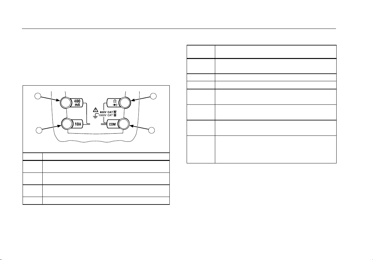
Terminals
.
1
V
FUSED
2
Item Description
Input terminal for AC and DC milliamp measurements to
1
400 mA.
Input terminal for AC and DC current measurements to
2
10 A.
Input terminal for voltage, continuity, resistance, diode
3
test, capacitance, and frequency measurements.
Common (return) terminal for all measurements.
4
3
4
AIK01F.EPS
Rotary Switch Positions
Switch
Position
AC voltage from 0.001 to 1000 V.
K
Hz
m
E
R
G
F
mA
F
BA
Frequency from 2 Hz to 99.99 kHz.
DC voltage from 1 mV to 1000 V.
L
DC mV from 0.1 mV to 600 mV.
L
Ohms from 0.1 Ω to 50 MΩ.
e
Farads from 1 nF to 9999 μF.
Beeper turns on at <25 Ω and turns off at >250 Ω.
Diode test. Displays OL above 2.4 V.
B
AC mA from 0.01 mA to 400 mA.
DC mA from 0.01 mA to 400 mA.
AC A from 0.001 A to 10 A.
DC A from 0.001 A to 10 A
>10.00 display flashes.
>20 A, OL is displayed.
Measurement Function
2
Page 7
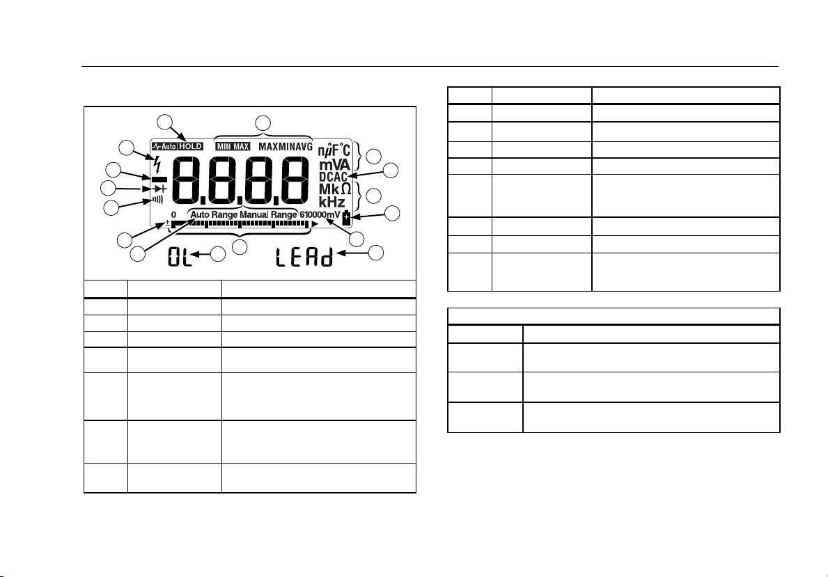
Display
Display
.
5
4
3
2
1
13
12
14
6
11
No. Symbol Meaning
1
s
2
O
3
K
4
Y
h
5
6
m
MAX , MIN,
AVG
7
nμ F, mVA,
Mke, kHz
Continuity test.
Diode test.
Negative readings.
Unsafe voltage. Voltage ≥30 V, or
voltage overload (OL)
AutoHOLD is enabled. Display holds
present reading until it detects new
stable input. Then the Meter beeps
and displays new reading.
MIN MAX AVG enabled.
Maximum, minimum, average, or
present reading.
Measurement units.
10
7
8
7
9
15
AIK02F.EPS
No. Symbol Meaning
8
9
10
11
12
13
14
15
DC, AC
b
610000mV
Bar graph
Auto Range
Manual Range
±
0L
LEAd
Direct current, alternating current.
Low battery. Replace battery.
All possible ranges.
Analog display.
The Meter selects the range with
the best resolution.
The user selects the range.
Bar graph polarity.
The input out of range.
WTest lead alert. Displayed when
the rotary switch is moved to or from
the mA or A position.
Error Messages
bAtt
diSC
Replace the battery immediately.
In the capacitance function, too much electrical
charge is present on the capacitor being tested.
EEPr
Invalid EEPROM data. Have Meter serviced.
Err
CAL
Invalid calibration data. Calibrate Meter.
Err
3
Page 8

Model 77 Series IV
Users Manual
MIN MAX AVG Recording Mode
The MIN MAX AVG recording mode captures the minimum and
maximum input values, and calculates a running average of all
readings. When a new high or low is detected, the Meter beeps.
Note
For dc functions, accuracy is the specified accuracy of the
measurement function
275 ms in duration.
For ac functions, accuracy is the specified accuracy of the
measurement function
1.2 s in duration.
To use MIN MAX AVG recording:
⇒ Make sure that the Meter is in the desired measurement
function and range. (Autoranging is disabled in the MIN MAX
AVG mode.)
⇒ Press MIN MAX to activate MIN MAX AVG mode.
m and MAX light, and the highest reading detected
since entering MIN MAX AVG is displayed.
⇒ Press MIN MAX to step through the low (MIN), average
(AVG), and present readings.
⇒ To pause MIN MAX AVG recording without erasing stored
values, press HOLD. h is displayed.
To resume MIN MAX AVG recording, press HOLD again.
h turns off.
⇒ To exit and erase stored readings, press MIN MAX for 1
second or turn the rotary switch.
±
12 counts for changes longer than
±
40 counts for changes longer than
AutoHOLD Modes
XWWarning
To avoid electric shock, do not use the AutoHOLD mode
to determine if a circuit is live. Unstable or noisy
readings will not be captured.
In the AutoHOLD mode, the Meter holds the reading on the display
until it detects a new stable reading. Then the Meter beeps, and
displays the new reading.
⇒ Press HOLD to activate AutoHOLD. h lights.
⇒ Press HOLD again or turn the rotary switch to resume normal
operation.
YELLOW Button
Press the yellow button to select alternate measurement functions
on a rotary switch setting, e.g., to select DC mA, DC A, Hz,
capacitance, or diode test.
Display Backlight
Press S to toggle the backlight on and off. The backlight
automatically turns off after 2 minutes.
4
Page 9
Manual Ranging and Autoranging
Manual Ranging and Autoranging
The Meter has both Manual range and Autorange modes.
⇒ In the Autorange mode, the Meter selects the range with the
best resolution.
⇒ In the Manual Range mode, you override Autorange and select
the range yourself.
When you turn the Meter on, it defaults to Autorange and Auto
Range is displayed.
1. To enter the Manual Range mode, press RANGE.
Manual Range is displayed.
2. In the Manual Range mode, press RANGE to increment the
range. After the highest range, the Meter wraps to the lowest
range.
Note
You cannot manually change the range in the MIN MAX
AVG mode.
If you press RANGE while in MIN MAX
beeps, indicating an invalid operation, and the range does
not change.
3. To exit Manual Range, press RANGE for 1 second or turn the
rotary switch.
The Meter returns to Autorange and Auto Range is displayed.
AVG, the Meter
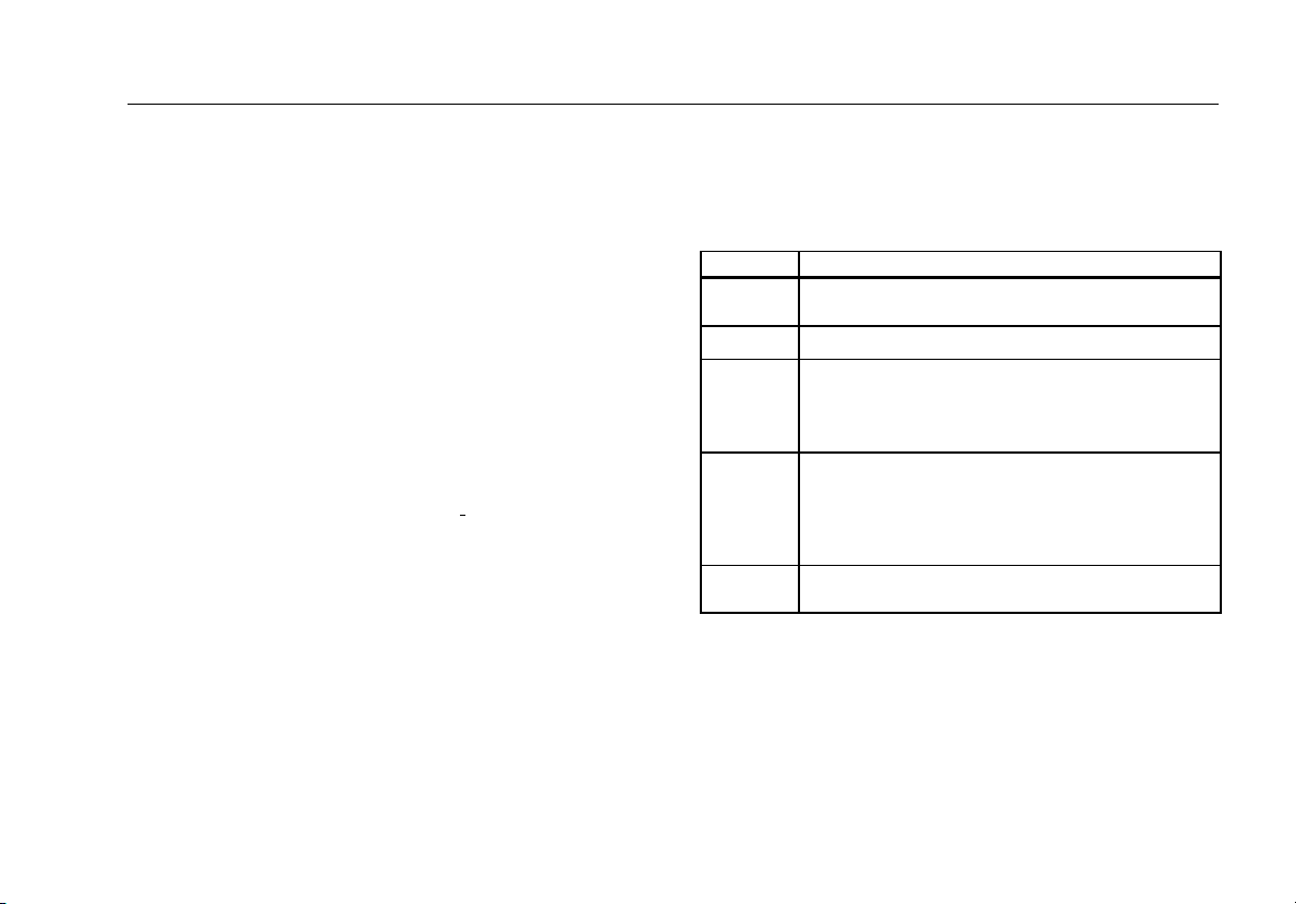
Power-Up Options
To select a Power-Up Option, hold down the button indicated while
turning the Meter on.
Power-Up Options are cancelled when the Meter is turned OFF.
Button Power-Up Options
Turns on all display segments when in VAC switch
H
M
R
B
(YELLOW)
S
position.
Disables beeper. bEEP is diplayed when enabled.
Enables "Smoothing" mode. '___ is displayed when
enabled.
Dampens display fluctuations of rapidly changing
inputs by digital filtering.
Disables automatic power-down ("Sleep mode").
PoFF is displayed when enabled
Sleep mode is also disabled while the Meter is in a
MIN MAX AVG Recording mode, or the AutoHOLD
mode.
Disables automatic 2-minute backlight timeout.
LoFF is displayed when enabled.
5
Page 10
Model 77 Series IV
Users Manual
Making Basic Measurements
The figures on the following pages show how to make basic
measurements.
When connecting the test leads to the circuit or device, connect
the common (COM) test lead before connecting the live lead;
when removing the test leads, remove the live lead before
removing the common test lead.
XWWarning
To avoid electric shock or injury, or damage to the
Meter, disconnect circuit power and discharge all highvoltage capacitors before testing resistance, continuity,
diodes, or capacitance.
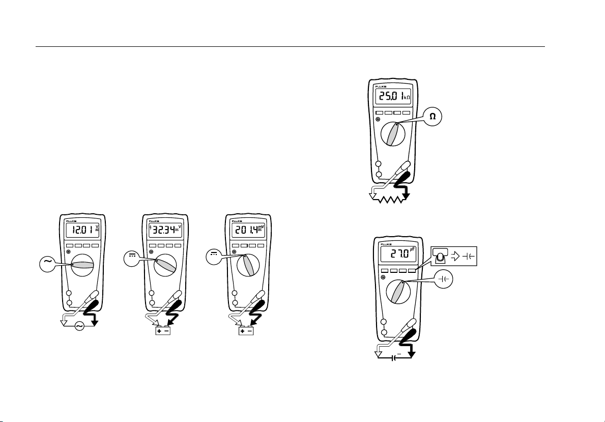
Measuring AC and DC Voltage
Volts AC
MIN MAX
RANGEHOLD
V
V
Volts DC
MIN MAX
+
Millivolts DC
RANGEHOLD
MIN MAX
RANGEHOLD
mV
_
+
AIK03F.EPS
Measuring Resistance
MIN MAX
RANGEHOLD
AIK04F.EPS
Measuring Capacitance
MIN MAX
RANGEHOLD
_
+
_
+
AIK05F.EPS
6
Page 11

Making Basic Measurements
Testing for Continuity
MIN MAX
RANGEHOLD
Testing Diodes
Good Diode Good Diode
MIN MAX
RANGEHOLD
AIK06F.EPS
MIN MAX
RANGEHOLD
+
Forward Bias
Bad Diode
MIN MAX
RANGEHOLD
CAT
+
MIN MAX
RANGEHOLD
__
+
Single Beep
Reverse Bias
Bad Diode
MIN MAX
RANGEHOLD
_
+
_
and
Open
Shorted
AIK07F.EPS
7
Page 12
Model 77 Series IV
Users Manual
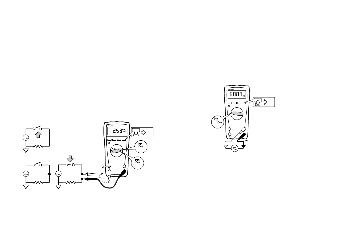
Measuring AC or DC Current
XWWarning
To avoid personal injury or damage to the Meter:
• Never attempt to make an in-circuit current measure-
ment when the open-circuit potential to earth ground
is >1000 V.
• Check the Meter's fuses before testing. (See “Testing
the Fuses”.)
• Use the proper terminals, switch position, and range
for your measurement.
• Never place the probes in parallel with a circuit or
component when the leads are plugged into the
current terminals.
Turn power OFF, break circuit, insert Meter in series, turn power
on.
DC
MIN MAX
RANGEHOLD
mA
+
+
A
CAT
CAT
AIK08F.EPS
Measuring Frequency
XWWarning
To avoid electrical shock, disregard the bar graph for
frequencies >1 kHz. If the frequency of the measured
signal is >1 kHz, the bar graph is unspecified.
The Meter measures the frequency of a signal. The trigger level is
0 V ac for all ranges.
AC Voltage Frequency
MIN MAX
RANGEHOLD
Hz
V
+
⇒ To exit frequency, press yellow button or turn the rotary
switch.
⇒ In frequency, the bar graph shows the ac voltage accurately
up to 1 kHz.
⇒ Select progressively lower ranges using manual ranging for a
stable reading.
EOM09F.EPS
8
Page 13
Using the Bar Graph
Using the Bar Graph
The bar graph is like the needle on an analog Meter. There is an
overload indicator (►) to the right, and a polarity indicator (±) to the
left.
Because the bar graph is much faster than the digital display, the
bar graph is useful for making peak and null adjustments, and for
observing rapidly changing inputs.
The bar graph is disabled when measuring capacitance. In
frequency, the bar graph accurately indicates the voltage or
current up to 1 kHz.
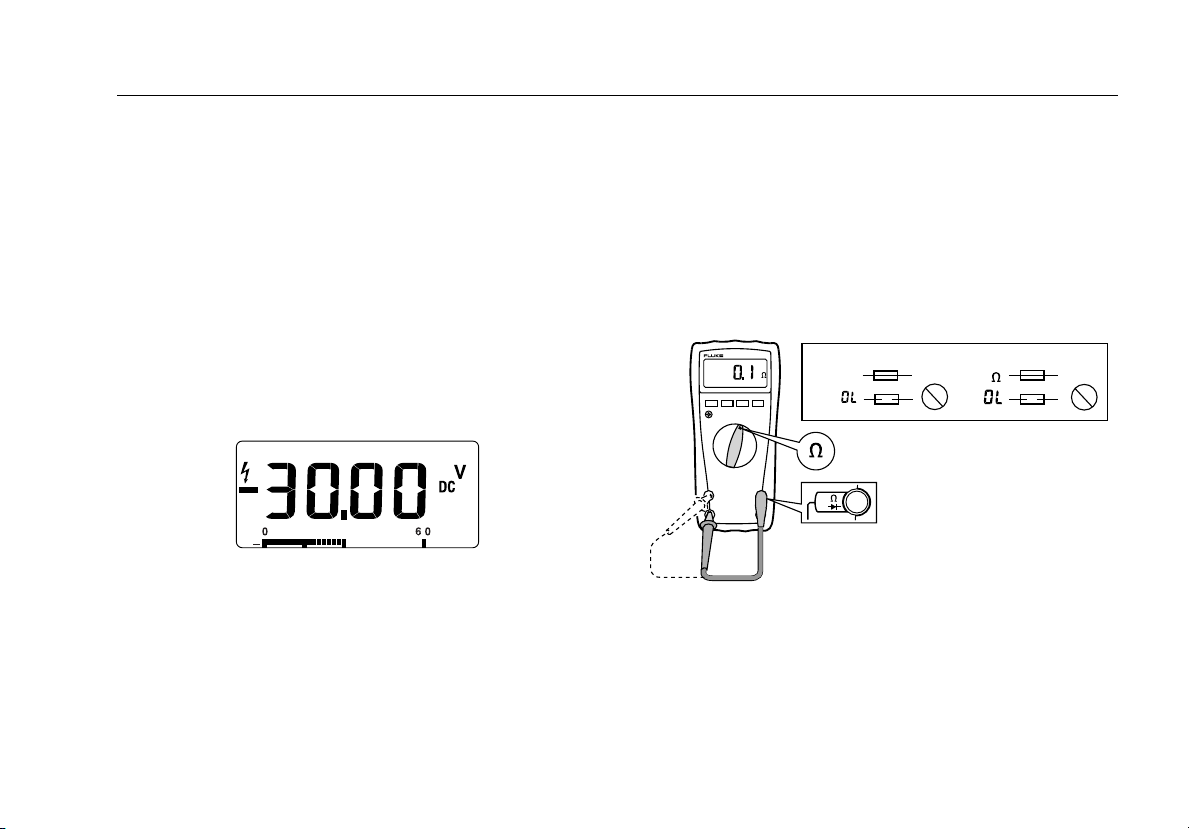
The number of lit segments indicates the measured value and is
relative to the full-scale value of the selected range.
For example, in the 60 V range (see below), the major divisions on
the scale represent 0, 15, 30, 45, and 60 V. An input of −30 V
lights the negative sign and the segments up to the middle of the
scale.
AIK11F.EPS
Cleaning
Wipe the case with a damp cloth and mild detergent. Do not use
abrasives or solvents. Dirt or moisture in the terminals can affect
readings.
Testing the Fuses
XWWarning
To avoid electrical shock or injury, remove the test
leads and any input signals before replacing the fuse.
Test fuses as shown below.
Ω
<12
MIN MAX
RANGEHOLD
V
<0.5
OK
11 A 440 mA
OKOK
OK
AIK12F.EPS
9
Page 14

Model 77 Series IV
Users Manual
Replacing the Battery and Fuses
XWWarning
To avoid shock, injury, or damage to the Meter:
• Use ONLY fuses with the amperage, interrupt,
voltage, and speed ratings specified. Disconnect test
leads before opening case.
I
B1
F1
F2
F1 Fuse, 440 mA, 1000 V, FAST Fluke PN 943121
F2 Fuse, 11 A, 1000 V, FAST Fluke PN 803293
B1 Battery, 9 V Alkaline,
NEDA 1604 / 1604A
10
Fluke PN 614487
b
AIK13F.EPS
Page 15

Specifications
Specifications
Accuracy is specified for 1 year after calibration, at operating temperatures of 18 °C to 28 °C, with relative humidity at 0 % to 90 %. Accuracy
specifications take the form of the following calculations:
Maximum voltage between any
terminal and earth ground: 1000
Surge Protection: 8 kV peak per IEC 61010
W Fuse for mA inputs:
W Fuse for A input:
Display: Digital: 6000 counts, updates 4/sec
440 mA, 1000 V FAST Fuse
11 A, 1000 V FAST Fuse
Bar Graph: 33 segments; updates 32/sec
Frequency: 10,000 counts
Capacitance: 1,000 counts
Altitude: Operating: 2000 m; Storage: 12,000 m
Temperature: Operating: −10 °C to +50 °C;
Temperature coefficient: 0.1 X (specified accuracy) / °C
Electromagnetic Compatibility
(EN 61326-1:1997):
Relative Humidity: Maximum, noncondensing
Storage: −40 °C to +60 °C
(<18 °C or >28 °C)
In an RF field of 3 V/M, accuracy = specified accuracy.
90 % to 35 °C
75 % to 40 °C;
45 % to 50 °C
Battery Life: Alkaline: 400 hrs typical
Size (H x W x L): 4.3 cm x 9 cm x 18.5 cm
Weight: 420 g
Safety Compliances: ANSI/ISA S82.02.01, CSA C22.2-1010.1, IEC 61010 to 1000 V Measurement Category III, 600 V Measurement
Category IV
Certifications: CSA, TÜV (EN61010), UL, P,
± ( [ % of Reading ] + [ Counts ] )
; (N10140),VDE
11
Page 16

Model 77 Series IV
Users Manual
Function
AC Volts (Average
responding)
6.000 V
60.00 V
600.0 V
1000 V
Range Resolution Accuracy ± ( [ % of Reading ] + [ Counts ] )
0.001 V
0.01 V
0.1 V
1 V
2.0 % + 2
(45 Hz to 1 kHz)
DC mV 600.0 mV 0.1 mV 0.3 % + 1
DC Volts 6.000 V
60.00 V
600.0 V
1000 V
Continuity 600 Ω 1 Ω Meter beeps at <25 Ω, beeper turns off at >250 Ω;
Ohms
600.0 Ω
6.000 kΩ
60.00 kΩ
600.0 kΩ
6.000 MΩ
50.00 MΩ
0.001 V
0.01 V
0.1 V
1 V
0.1 Ω
0.001 kΩ
0.01 kΩ
0.1 kΩ
0.001 MΩ
0.01 MΩ
0.3 % + 1
detects opens or shorts of 250 μs or longer.
0.5 % + 2
0.5 % + 1
0.5 % + 1
0.5 % + 1
0.5 % + 1
2.0 % + 1
Diode test 2.400 V 0.001 V 1 % + 2
Capacitance
AC Amps (Average
responding)
[1] In the 9999 μF range for measurements to 1000 μF, the measurement accuracy is 1.2 % + 2.
[2] Amps input burden voltage (typical): 400 mA input 2 mV/mA, 10 A input 37 mV/A.
[3] 400.0 mA accuracy specified up to 600 mA overload.
[4] >10 A unspecified.
[2]
1000 nF
10.00 μF
100.0 μF
9999 μF
60.00 mA
400.0 mA
6.000 A
[4]
10.00 A
1 nF
0.01 μF
[1]
[3]
0.1 μF
1 μF
0.01 mA
0.1 mA
0.001 A
0.01 A
1.2 % + 2
1.2 % + 2
1.2 % + 2
10 % typical
2.5 % + 2
(45 Hz to 1 kHz)
12
Page 17

Specifications
Function
DC Amps
Hz
(ac voltage input )
MIN MAX AVG For dc functions, accuracy is the specified accuracy of the measurement function ±12 counts for changes longer than
[3]
[1][ 2]
60.00 mA
400.0 mA
6.000 A
10.00 A
99.99 Hz
999.9 Hz
9.999 kHz
99.99 kHz
275 ms in duration.
For ac functions, accuracy is the specified accuracy of the measurement function ±40 counts for changes longer than
1.2 s in duration.
[1] Frequency is specified from 2 Hz to 99.99 kHz.
[2] Below 2 Hz, the display shows zero Hz.
[3] Amps input burden voltage (typical): 400 mA input 2 mV/mA, 10 A input 37 mV/A.
[4] 400.0 mA accuracy specified up to 600 mA overload.
[5] >10 A unspecified.
Range Resolution Accuracy ± ( [ % of Reading ] + [ Counts ] )
[4]
[5]
0.01 mA
0.1 mA
0.001 A
0.01 A
0.01 Hz
0.1 Hz
0.001 kHz
0.01 kHz
1.5 % + 2
0.1 % + 1
13
Page 18

Model 77 Series IV
Users Manual
Function Overload Protection
Input Impedance
(Nominal)
Common Mode Rejection Ratio
(1 kΩ Unbalanced)
Normal Mode Rejection
[1]
Volts AC 1000 V >10 MΩ <100 pF >60 dB @ dc, 50 Hz or 60 Hz
Volts DC 1000 V >10 MΩ <100 pF >120 dB @ dc, 50 Hz or 60 Hz >60 dB @ 50 Hz or 60 Hz
mV 1000 V
Open Circuit Test
Ohms/Capacitance 1000 V
Continuity/Diode test 1000 V
[1] 10
7
V-Hz maximum.
[2]
>10 MΩ <100 pF >120 dB @ dc, 50 Hz or 60 Hz >60 dB @ 50 Hz or 60 Hz
Voltage
[2]
<8.0 V dc <660 mV dc <4.6 V dc <1.1 mA
[2]
<8.0 V dc 2.4 V dc <1.1 mA
Full Scale Voltage To:
6.0 MΩ 50 MΩ
Short Circuit Current
[2] For circuits <0.3 A short circuit. 660 V for high energy circuits.
Function Overload Protection Overload
mA Fused, 440 mA, 1000 V FAST Fuse 600 mA overload for 2 minutes maximum, 10
A Fused, 11 A, 1000 V FAST Fuse 20 A overload for 30 seconds maximum, 10
minutes rest.
minutes rest.
14
Page 19

Manual Supplement
Manual Title: 77 Series IV Users Supplement Issue: 1
Part Number: 2695884 Issue Date: 10/06
Print Date: September 2006 Page Count: 1
Revision/Date:
This supplement contains information necessary to ensure the accuracy of the
above manual.
© 2006 Fluke Corporation. All rights reserved. Printed in the U.S.A. x
Page 20

77 Series IV Users Manual Supplement
Change #1 - 38525
On page 4, under MIN MAX AVG Recording Mode, under the note replace the last part of both
sentences with the following:
………….changes longer than 350 ms in duration.
On page 13, under Function, replace the MIN MAX AVG, row with the following:
For dc functions, accuracy is the specified accuracy of the measurement function ±12 counts
MIN MAX AVG
for changes longer than 350 ms in duration.
For ac functions, accuracy is the specified accuracy of the measurement function ±40 counts
for changes longer than 350 ms in duration.
Change #2
On page 5, under Manual Ranging and Autoranging, replace the second paragraph under the
note with the following:
If you press RANGE while in MIN MAX_AVG, the meter beeps twice, indicating an invalid operation, and the
range does not change.
10/06 1
Page 21

Model 77 Series IV
Digital Multimeter
Calibration Information
Introduction
XWWarning
To avoid electric shock or injury, do not perform the performance tests or
calibration adjustment procedures unless qualified to do so.
The information provided in this document is for the use of qualified personnel
only.
The Model 77 Series IV Calibration Information provides the information necessary to adjust and verify
the performance of the Fluke Model 77 Series IV Digital Multimeter (hereafter known as the Meter).
®
The following information is included in this document:
• Safety Information (page 2)
• International Electrical Symbols (page 3)
• Test Lead Alert (page 3)
• Specifications (page 4)
• Testing and Replacing the Fuses (page 7)
• Replacing the Battery (page 8)
• Cleaning (page 9)
• Replacing the LCD (page 9)
• Performance Tests (page 10)
• Calibration Adjustment (page 14)
• Replaceable Parts and Accessories (page 17)
• Complete Warranty (page 19)
See the Model 77 Series IV Users Manual for complete operating instructions.
Service Information
To contact Fluke, call one of the following telephone numbers:
USA: 1-888-99-FLUKE (1-888-993-5853)
Canada: 1-800-36-FLUKE (1-800-363-5853)
Europe: +31 402-675-200
Japan: +81-3-3434-0181
Singapore: +65-738-5655
Anywhere in the world: +1-425-446-5500
Or, visit Fluke's Web site at www.fluke.com
To register your product, visit register.fluke.com
September 2006
© 2006 Fluke Corporation. All rights reserved.
1
.
Page 22

Model 77 Series IV
Calibration Information
Safety Information
Warning and Caution Statements
A XW Warning identifies hazardous conditions and actions that could cause bodily harm or death.
A W Caution identifies conditions and actions that could damage the Meter, the equipment under test, or
cause permanent loss of data.
XWWarnings and Precautions
To avoid possible electric shock or personal injury, and to avoid possible damage to the Meter
or to the equipment under test, adhere to the following practices:
• Use the Meter only as specified in this manual or the protection provided by the Meter might
be impaired.
• Do not use the Meter or test leads if they appear damaged, or if the Meter is not operating
properly. If in doubt, have the Meter serviced.
• Always use the proper terminals, switch position, and range for measurement.
• Verify the Meter's operation by measuring a known voltage.
• Do not apply more than the rated voltage, as marked on the Meter, between the terminals or
between any terminal and earth ground.
• Use caution with voltages above 30 V ac rms, 42 V ac peak, or 60 V dc. These voltages pose
a shock hazard.
• Disconnect circuit power and discharge all high-voltage capacitors before testing
resistance, continuity, diodes, or capacitance.
• Do not use the Meter around explosive gas or vapor.
• When using the test leads, keep your fingers behind the finger guards.
• Remove test leads from the Meter before opening the Meter case or battery door.
2
Page 23

Digital Multimeter
International Electrical Symbols
International Electrical Symbols
The following international symbols appear in this document, and on the Meter.
Symbols Description Symbols Description
B
F
F
B
J
W
b
s
#
AC (Alternating Current)
DC (Direct Current)
DC/AC
Earth ground
Important Information; see manual.
Battery. (Low battery when shown on
display)
Inspected and licensed by TÜV
(Technischer Überwachungs Verein)
Product Services
Verband Deutscher Electroniker. German electronics association.
Test Lead Alert
Attempting to make a measurement with a test lead in an incorrect terminal
might blow a fuse, damage the Meter, and cause serious personal injury.
I
P
$
T
X
Fuse
Conforms to European Union directives
Conforms to relevant Canadian Standards
Association directives
Double-insulated
Hazardous Voltage
Underwriters Laboratories, Inc.
!
Meter in accordance with IEC 61010-1. 54CJ
;
.
XWWarning
N10140
Conforms to relevant Australian standards
As a reminder to check that the test leads are in the correct terminals, LEAd is momentarily displayed when
the Rotary Switch is moved to
or from the mA or A position.
3
Page 24

Model 77 Series IV
Calibration Information
Specifications
Accuracy is specified for 1 yr after calibration, at operating temperatures of 18 °C to 28 °C, with relative humidity at 0 % to 90 %. Accuracy
specifications take the form of ±([ % of Reading ] + [ Counts ]).
Maximum voltage between any
terminal and earth ground ................................... 1000 V
Surge protection ................................................... 8 kV peak per IEC 61010
W Fuse for mA inputs.......................................... 440 mA, 1000 V FAST Fuse
W Fuse for A inputs ............................................. 11 A, 1000 V FAST Fuse
Display
Digital.............................................................. 6000 counts, updates 4/sec
Bar Graph ....................................................... 33 segments; Updates 32/sec
Frequency....................................................... 10,000 counts
Capacitance.................................................... 1,000 counts
Altitude
Operating............................................................ 2,000 meters
Storage ............................................................... 12,000 meters
Temperature
Operating........................................................ -10 °C to +50 °C
Storage ........................................................... -40 °C to +60 °C
Temperature coefficient ....................................... 0.1 X (specified accuracy / °C (<18 °C or >28 °C)
Electromagnetic Compatibility
(EN 61326-1:1997) ................................................. In an RF field of 3 V/M, accuracy = specified accuracy except in temperature: specified
Relative Humidity (Maximum Non-condensing). 90 % to 35 °C
Battery Life ............................................................ 400 hrs typical (Alkaline)
Size (H x W x L) ..................................................... 4.3 cm x 9 cm x 18.5 cm
Weight.................................................................... 420 g
Safety Compliance................................................ ANSI/ISA S82.02.01, CSA C22.2-1010.1, IEC 61010 to 1000 V Measurement Category
Certifications......................................................... CSA, TÜV (EN61010), UL, P, ; (N10140),VDE
accuracy ± 5 °C (9 °F)
75 % to 40 °C;
45 % to 50 °C
III, 600 V Measurement Category IV
4
Page 25

Digital Multimeter
Specifications
Function Range Resolution Accuracy ± ( [ % of Reading ] + [ Counts ] )
AC Volts (Average
responding)
6.000 V
60.00 V
600.0 V
1000 V
0.001 V
0.01 V
0.1 V
1 V
2.0 % + 2
(45 Hz to 1 kHz)
DC mV 600.0 mV 0.1 mV 0.3 % + 1
DC Volts 6.000 V
60.00 V
600.0 V
1000 V
Continuity 600 Ω 1 Ω Meter beeps at <25 Ω, beeper turns off at >250 Ω;
Ohms
600.0 Ω
6.000 kΩ
60.00 kΩ
600.0 kΩ
6.000 MΩ
50.00 MΩ
0.001 V
0.01 V
0.1 V
1 V
0.1 Ω
0.001 kΩ
0.01 kΩ
0.1 kΩ
0.001 MΩ
0.01 MΩ
0.3 % + 1
detects opens or shorts of 250 μs or longer.
0.5 % + 2
0.5 % + 1
0.5 % + 1
0.5 % + 1
0.5 % + 1
2.0 % + 1
Diode test 2.400 V 0.001 V 1 % + 2
Capacitance
AC Amps (Average
responding)
Notes:
[1] In the 9999 μF range for measurements to 1000 μF, the measurement accuracy is 1.2 % + 2.
[2] Amps input burden voltage (typical): 400 mA input 2 mV/mA, 10 A input 37 mV/A.
[3] 400.0 mA accuracy specified up to 600 mA overload.
[4] >10 A unspecified.
[2]
1000 nF
10.00 μF
100.0 μF
9999 μF
60.00 mA
400.0 mA
6.000 A
[4]
10.00 A
1 nF
0.01 μF
[1]
[3]
0.1 μF
1 μF
0.01 mA
0.1 mA
0.001 A
0.01 A
1.2 % + 2
1.2 % + 2
1.2 % + 2
10 % typical
2.5 % + 2
(45 Hz to 1 kHz)
Function Range Resolution Accuracy ± ( [ % of Reading ] + [ Counts ] )
DC Amps
Hz
(ac voltage input )
MIN MAX AVG For dc functions, accuracy is the specified accuracy of the measurement function ±12 counts for changes longer than
[3]
[1], [2]
60.00 mA
400.0 mA
6.000 A
[5]
10.00 A
99.99 Hz
999.9 Hz
9.999 kHz
99.99 kHz
[4]
0.01 mA
0.1 mA
0.001 A
0.01 A
0.01 Hz
0.1 Hz
0.001 kHz
0.01 kHz
350 ms in duration.
For ac functions, accuracy is the specified accuracy of the measurement function ±40 counts for changes longer than
350 ms in duration.
Notes:
[1] Frequency is specified from 2 Hz to 99.99 kHz.
[2] Below 2 Hz, the display shows zero Hz.
[3] Amps input burden voltage (typical): 400 mA input 2 mV/mA, 10 A input 37 mV/A.
[4] 400.0 mA accuracy specified up to 600 mA overload.
[5] >10 A unspecified.
1.5 % + 2
0.1 % + 1
5
Page 26

Model 77 Series IV
Calibration Information
Function
Volts AC 1000 V >10 MΩ <100 pF >60 dB @ dc, 50 Hz or 60 Hz
Volts DC 1000 V >10 MΩ <100 pF >120 dB @ dc, 50 Hz or 60 Hz >60 dB @ 50 Hz or 60 Hz
mV 1000 V2 >10 MΩ <100 pF >120 dB @ dc, 50 Hz or 60 Hz >60 dB @ 50 Hz or 60 Hz
Ohms/Capacitance 1000 V2 < 8.0 V dc <660 mV dc <4.6 V dc <1.1 mA
Continuity/Diode test 1000 V2 <8.0 V dc 2.4 V dc <1.1 mA
7
[1] 10
[2] For circuits <0.3 A short circuit. 660 V for high energy circuits.
V-Hz maximum.
Overload
Protection
[1]
Input Impedance
(Nominal)
Open Circuit Test
Voltage
Common Mode Rejection Ratio
(1 kΩ Unbalanced)
Full Scale Voltage To:
6.0 MΩ 50 MΩ
Normal Mode Rejection
Short Circuit Current
Function Overload Protection Overload
mA Fused, 440 mA, 1000 V FAST Fuse 600 mA overload for 2 minutes maximum, 10
A Fused, 11 A, 1000 V FAST Fuse 20 A overload for 30 seconds maximum, 10
minutes rest.
minutes rest.
6
Page 27

Digital Multimeter
Testing the Fuses
Testing the Fuses
XWWarning
To avoid electrical shock or personal injury:
• Remove the test leads and any input signals before replacing the battery or
fuses.
• To avoid electrical shock, arc blast, or damage to the Meter, install only
fuses with the amperage, interrupt, voltage, and speed ratings specified in
Table 4.
To test the fuses (refer to Figure 1):
1. Set the Rotary Switch to e.
2. Plug a test lead into the VeG terminal and touch the probe to the
400 mA to test the 440 mA Fuse or
10 A terminal to test the 11 A Fuse.
• If the display shows a resistance value in the range shown in Figure 1, the fuse is good.
• If the display reads
OL, replace the fuse and test again.
• If the display shows any other value, have the Meter serviced. See “Service Information” earlier in
this manual.
11 A 440 mA
OKOK
OK
MIN MAX
Ω
<12
RANGEHOLD
V
<0.5
OK
Figure 1. Testing the Current Fuses
aik12f.eps
7
Page 28

Model 77 Series IV
Calibration Information
Replacing the Fuses
XWWarning
To avoid electrical shock, arc blast, or damage to the Meter, install only fuses
with the amperage, interrupt, voltage, and speed ratings specified in
Table 4.
To replace the Fuses (refer to Figure 2):
1. Turn the Rotary Switch to
OFF.
2. Disconnect the test leads and/or any connectors from the terminals.
3. Remove the four screws from the Case Bottom and separate the Case Top from the Case Bottom.
4. Remove the fuses F1 and F2 by gently prying one end loose, then slide the fuse out of its bracket, and
replace with exact replacement only.
5. Rejoin the Case Bottom, Case Top, Battery compartment door, and reinstall the four screws.
Replacing the Battery
To replace the Battery (refer to Figure 2):
1. Turn the Rotary Switch to
OFF and remove the test leads from the terminals.
2. Remove the two screws from the Battery Compartment Door, and remove it from the Case Bottom.
3. Remove the Battery (B1) from the battery connector.
4. Replace the Battery with a new 9 V battery (NEDA A1604, 6F22, or 006P).
5. Reattach the Battery Compartment Door to the Case Bottom, and reinstall the two screws.
B1
F1
F2
8
Figure 2. Battery and Fuse Replacement
aik13f.eps
Page 29

Digital Multimeter
Cleaning
Cleaning
XWWarning
To avoid electrical shock:
• Remove test leads and any input signals before cleaning.
• Do not reinstall the pca until it is completely dry.
• Dirt or moisture in the terminals can affect readings.
W Caution
To avoid damaging the Meter, do not use aromatic hydrocarbons or chlorinated
solvents for cleaning. These solutions will react with the plastics used in the
instruments.
Do not use detergents of any kind for cleaning the pca.
Clean the instrument case with a damp cloth and mild detergent.
The pca may be washed with isopropyl alcohol or hot deionized water and a soft brush. Remove excess
cleaning material with clean dry air at low pressure, then dry the pca at 50 °C.
Replacing the LCD
W Caution
To prevent contamination, do not handle the conductive edges of the LCD or
the LCD Elastomeric Connectors.
If the edges are contaminated, clean them with alcohol. Allow the alcohol to dry
before reassembling.
To remove and replace the LCD, perform the following procedure (refer to Figure 3):
1. Turn the rotary switch to
2. Remove the four screws from the case bottom, and separate the case top from the case bottom
The circuit board remains attached to the case bottom.
3. Remove the battery compartment and disconnect the battery from the battery connector.
4. Remove the pca screw located under the 440 mA fuse, and lift the pca out of the case bottom. The
beeper is loose in the case. Exercise caution not to damage it.
5. Loosen the four screws in the area of the LCD on the back of the pca. This will facilitate reinstalling
the LCD.
6. Insert a small, flat-head screwdriver under the LCD mask edge and gently pry the LCD mask from the
snaps.
Take care to not break the LCD with the screwdriver.
7. Lift out the LCD.
8. Make sure that all connector contact points are clean. Refer to “Cleaning” for more information.
9. Install a new LCD, taking care that it is correctly oriented.
10. Reattach the LCD Mask to the LCD assembly by snapping the LCD mask into place.
11. Tighten the 4 screws on the back of the pca.
12. Lay the pca back into the case bottom, and screw it down.
13. Reinsert the 440 mA Fuse.
14. Reinstall the battery.
15. Rejoin the case bottom, case top, battery compartment door, and reinstall the four case screws.
OFF and remove the test leads from the Meter terminals.
W Caution
9
Page 30

Model 77 Series IV
Calibration Information
LCD Mask
Figure 3. Removing the LCD Mask
aik15f.eps
Performance Tests
The following performance tests verify the complete operation of the Meter and check the accuracy of
each Meter function against its specifications. The recommended calibration interval is 12 months. If the
Meter fails any part of the test, calibration adjustment and/or repair is indicated.
In the performance tests, the Meter is referred to as the unit under test (UUT).
10
Page 31

Digital Multimeter
Performance Tests
Required Equipment
A Fluke 5500A Multi-Product Calibrator (or equivalent) is required for the performance test procedures in
this document.
If an equivalent calibrator is used, it must meet the accuracy specifications shown in Table 1.
Table 1. Calibrator Specifications
Recommended Equipment Measurement Function Minimum required accuracy
5500A Multi-Product Calibrator
(or equivalent)
DC Volts 30 mV to 1000 V ±0.075 %
DC Current 3 mA to 9 A
AC Volts 50 mV to 1000 V ±0.5 % @ 45 Hz to 1 kHz
AC Current 0.5 mA to 9 A
Resistance 25 Ω to 5 MΩ
Capacitance 900 nF
Frequency 5 V, 50 kHz
Preparing for the Performance Test
To avoid possible electric shock or personal injury:
• Do not perform the following procedures unless qualified to do so. Some
procedures involve the use of high voltages.
±0.375 %
±0.625 % @ 45 Hz to 1 kHz
±0.125 %
10 MΩ to 40 MΩ
±0.5 %
±0.3 %
±0.025 %
XWWarning
• Before handling the test connections, and in between tests, make sure the
calibrator is in standby (STBY) mode.
• Do not perform the performance test procedures unless the Meter is fully
assembled
To prepare for the performance test:
1. Make sure that you have the required equipment (refer to Table 1).
2. Warm up the calibrator as required by its specifications.
3. Allow the temperature of the UUT to stabilize at room temperature ( 23 °C ± 5 °C [73 °F ± 9 °F] ).
4. Check the fuses and Battery, and replace them if necessary. Refer to Testing the Fuses, Replacing the
Fuses, and Replacing the Battery.
11
Page 32

Model 77 Series IV
Calibration Information
Performance Tests
Note
When calibrating or measuring ac current, avoid the potential for errors from coupled noise by either:
1. Shorting the VeG to the COM input
or
2. Having no connection to the VeG input.
1. Set the Meter’s Rotary Switch to the position called for in Table 2, and for all measurements other than
current (amps), connect the calibrator to the VeG and
COM input terminals.
• If testing the milliamps function, connect the calibrator to the Meter
400 mA and COM input
terminals.
• If testing the amps function, connect the calibrator to the Meter
10A and COM input terminals.
2. Referring to Table 2 or Table 3, apply the indicated calibrator output voltages to the UUT for each test.
3. Verify that the UUT displays a reading that is within the limits shown in the Meter Response column.
Table 2. Performance Tests
Meter Response
Steps Test
(Switch Position)
1 500 Ω 497.3 Ω 502.7 Ω
2 50 kΩ 49.74 kΩ 50.26 kΩ
3 5 MΩ 4.974 MΩ 5.026 MΩ
4 10 MΩ 9.79 MΩ 10.21 MΩ
5
6 25 Ω Beeper On
7
8 50 mV 45 Hz 0.47 V ac 0.53 V ac
9 5 V 45 Hz 4.898 V ac 5.102 V ac
10 5 V 1 kHz 4.898 V ac 5.102 V ac
11 50 V 45 Hz 48.98 V ac 51.02 V ac
12 50 V 1 kHz 48.98 V ac 51.02 V ac
13 500 V 45 Hz 489.8 V ac 510.2 V ac
14 500 V 1 kHz 489.8 V ac 510.2 V ac
15 1000 V 45 Hz 978 V ac 1022 V ac
16
17 K Hz
e
[2]
Ohms
R
Continuity
K
AC Volts
AC Volts Frequency
40 MΩ 39.19 MΩ 40.81 MΩ
250 Ω
1000 V 1 kHz 978 V ac 1022 V ac
[1]
5 V 50 kHz 49.94 kHz 50.06 kHz
5500 Output
Lower Limit
Upper Limit
Beeper Off
12
Page 33

Digital Multimeter
Performance Tests
Table 2. Performance Tests (cont)
Meter Response
Steps
Test
(Switch Position)
5500 Output
Lower Limit
Upper Limit
18 5 V 4.984 V dc 5.016 V dc
19 300 V 299.0 V dc 301.0 V dc
L
20 1000 V 996 V dc 1004 V dc
21
22 30 mV 29.8 mV dc 30.2 mV dc
23 -300 mV -301.0 mV dc -299.0 mV dc
24
25 E
26 0.5 mA 45 Hz 0.47 mA ac 0.53 mA ac
27 50 mA 1 kHz 48.73 mA ac 51.27 mA ac
28
29 4.0 A 45 Hz 3.898 A ac 4.102 A ac
30
31 3 mA, 0 Hz 2.93 mA dc 3.07 mA dc
32 50 mA 49.23 mA dc 50.77 mA dc
33
DC Volts
E
DC Millivolts
Capacitance
G
Diode Test
[1]
F
AC Milliamps
?
AC Amps
mI
DC Milliamps
-1000 V -1004 V dc -996 V dc
600 mV 598.1 mV dc 601.9 mV dc
[1]
[1]
Apply 900 nF 887 nF 913 nF
400 mA 1 kHz 389.8 mA ac 410.2 mA ac
9.0 A 1 kHz 8.75 A ac 9.25 A ac
-400 mA −406.2 mA dc −393.8 mA dc
34 4.0 A 3.938 A dc 4.062 A dc
35
1. Press the YELLOW button to access this function.
2. Does not include test lead resistance.
A
DC Amps1
-9.0 A −9.16 A dc −8.84 A dc
13
Page 34

Model 77 Series IV
Calibration Information
Calibration Adjustment
Perform the calibration adjustment procedures if the Meter fails the performance tests.
The Meter buttons behave as follows when the calibration mode is enabled:
H
M
B
Calibration Adjustment Procedure
Use the following steps to adjust the Meter’s calibration:
1. Turn the Meter over and find the Calibration Seal located near the top of the Meter (refer to Figure 4).
2. With a small probe, break the Calibration Seal and press the Calibration Button for 1 second. The
3. Proceed through the calibration steps by entering the input value listed in the table for each step.
When calibrating or measuring ac current, avoid the potential for errors from coupled noise by either:
Press and hold this button to test the present function. This measurement is uncalibrated and
may be inaccurate. This is normal.
Press and hold this button to display the required input.
Press this YELLOW button to store the calibration value and advance to the next step. This
button is also used to exit calibration mode after the calibration adjustment sequence is
complete.
Switch the Meter to
Meter will beep and change to the calibration mode. The display reads C-01, designating the first
calibration step. The Meter remains in calibration mode until the Rotary Function Switch is turned off.
1. Shorting the VeG to the COM input
or
E
DC.
Note
2. Having NO connection to the VeG input.
Note
After pressing the yellow button, wait until the step number advances before changing the calibrator
source or turning the Rotary Switch.
4. After each input value is applied, press the yellow button to accept the value and proceed to the next
step (C-02 and so forth).
5. When the last step in a function is reached, turn the Rotary Function Knob to the next required
function. The Meter will not allow a step to be completed if the Rotary Function Knob is turned to the
wrong function.
Note
If the calibration adjustment procedure is not completed correctly, the Meter will not operate
correctly. When calibration adjustment is not performed correctly, the Meter displays the messages
CAL and Errand the Meter must be recalibrated.
The Meter is damaged and requires service if:
• CAL and Err messages continue to appear after a proper recalibration.
• EEPr and Err messages are alternating on the display.
• EEPr message appears on the display.
14
Page 35

Digital Multimeter
Calibration Adjustment
Calibration Seal
Calibration Button
aik14f.eps
Figure 4. Calibration Access
15
Page 36

Model 77 Series IV
Calibration Information
Table 3. Calibration Steps
Function
(Switch Position)
E
(DC Millivolts)
L
(DC Volts)
C
(AC Volts)
e
(Ohms)
O
(Diode Test)
(Milliamps)
(Amps)
* If the Meter is not connected correctly, or if the rotary switch is in the wrong position, the Meter will beep 2 times to alert the user.
Calibration Step
C-01 600.0 mV dc
C-02
C-03 6.000 V dc
C-04 60.00 V dc
C-05 600.0 V dc
C-06 600.0 mV, 60 Hz
C-07 600.0 V, 60 Hz
C-08
C-09 6.000 kΩ
C-10 60.00 kΩ
C-11 600.0 kΩ
C-12 6.000 MΩ
C-13 5.000 V dc
C-14 400.0 mA dc mA
C-15 400.0 mA ac, 60 Hz
C-16 6.000 A dc A
C-17 6.000 A ac, 60 Hz
120.0 mV dc
600.0 Ω
Input Value
16
Page 37

Digital Multimeter
Replaceable Parts and Accessories
Replaceable Parts and Accessories
Replaceable parts and accessories are shown in Table 4 and Figure 5.
XW Warning
To avoid electric shock, injury, or damage to the meter, use exact replacement
parts only.
Table 4. Replaceable Parts
Item Description Part No Qty
-- (Not shown) TL75 Test Lead Set* 855705 1
--
1 Case Top 2695766 1
2 Window 648714 1
3 Shock Absorber 428441 1
4 Keypad 1560052 1
5 LCD Mask 2695775 1
6 LCD 1560856 1
7 LCD Light Pipe
8 WFuse, 11 A, (fast acting), 1000 V ac/dc, minimum interrupt rating 17 kA 803293 1
9 WFuse, 440 mA (fast acting), 1000 V ac/dc, minimum interrupt rating 10 kA 943121 1
10 PCA Screw
11 AC Shield
12 AC Shield and Internal Cover screws 448456 5
13 Case Bottom (includes bottom shield and calibration button) 2095692 1
14 Battery, 9 V (Alkaline, 9 V, 0-200 mA) 614487 1
15 Battery Compartment Door 1564799 1
16 Case Screws 832246 4
17 Tilt Stand 648961 1
18 LCD Elastomeric Connector 650264 2
19 Internal Cover 1564786 1
20 Battery Connector 1988201 1
21 Beeper 2041050 1
22 Swtich Detent Spring 822643 1
23 Switch Knob 648706 1
24 Calibration Button 1564889 1
* Fluke accessories are available from your authorized Fluke distributor.
(Not Shown)
77 Series IV Users Manual (English only)
77 Series IV Users Manual CD (English, and all translated versions)
2695884
2695825
1564806
1626602
648755
1
1
1
1
1
17
Page 38

Model 77 Series IV
Calibration Information
17
16
15
21
20
14
13
12
24
11
18
19
10
9
7
8
6
18
22
3
23
Figure 5. Replaceable Parts and Accessories
5
4
2
1
aik16f.eps
Page 39

Digital Multimeter
Replaceable Parts and Accessories
Lifetime Limited Warranty
Each Fluke 20, 70, 80, 170, and 180 Series DMM will be free from defects in material and workmanship for its lifetime. As
used herein, “lifetime” is defined as seven years after Fluke discontinues manufacturing the product, but the warranty
period shall be at least ten years from the date of purchase. This warranty does not cover fuses, disposable batteries,
damage from neglect, misuse, contamination, alteration, accident or abnormal conditions of operation or handling, including
failures caused by use outside of the product’s specifications, or normal wear and tear of mechanical components. This
warranty covers the original purchaser only and is not transferable.
For ten years from the date of purchase, this warranty also covers the LCD. Thereafter, for the lifetime of the DMM, Fluke
will replace the LCD for a fee based on then current component acquisition costs.
To establish original ownership and prove date of purchase, please complete and return the registration card
accompanying the product, or register your product on http://www.fluke.com
replace or refund the purchase price of a defective product purchased through a Fluke authorized sales outlet and at the
applicable international price. Fluke reserves the right to charge for importation costs of repair/replacement parts if the
product purchased in one country is sent for repair elsewhere.
If the product is defective, contact your nearest Fluke authorized service center to obtain return authorization information,
then send the product to that service center, with a description of the difficulty, postage and insurance prepaid (FOB
Destination). Fluke assumes no risk for damage in transit. Fluke will pay return transportation for product repaired or
replaced in-warranty. Before making any non-warranty repair, Fluke will estimate cost and obtain authorization, then
invoice you for repair and return transportation.
THIS WARRANTY IS YOUR ONLY REMEDY. NO OTHER WARRANTIES, SUCH AS FITNESS FOR A PARTICULAR
PURPOSE, ARE EXPRESSED OR IMPLIED. FLUKE SHALL NOT BE LIABLE FOR ANY SPECIAL, INDIRECT,
INCIDENTAL OR CONSEQUENTIAL DAMAGES OR LOSSES, INCLUDING LOSS OF DATA, ARISING FROM ANY
CAUSE OR THEORY. AUTHORIZED RESELLERS ARE NOT AUTHORIZED TO EXTEND ANY DIFFERENT
WARRANTY ON FLUKE’S BEHALF. Since some states do not allow the exclusion or limitation of an implied warranty or
of incidental or consequential damages, this limitation of liability may not apply to you. If any provision of this warranty is
held invalid or unenforceable by a court or other decision-maker of competent jurisdiction, such holding will not affect the
validity or enforceability of any other provision.
Fluke Corporation Fluke Europe B.V.
P.O. Box 9090 P.O. Box 1186
Everett, WA 98206-9090 5602 BD Eindhoven
U.S.A. The Netherlands
. Fluke will, at its option, repair at no charge,
2/02
19
Page 40

Model 77 Series IV
Calibration Information
20
Page 41

Manual Supplement
Manual Title: 77 Series IV Calibration Supplement Issue: 1
Print Date: September 2006 Issue Date: 3/07
Revision/Date: Page Count: 1
This supplement contains information necessary to ensure the accuracy of
the above manual. Enter the corrections in the manual if either one of the
following conditions exist:
1. The revision letter stamped on the indicated PCA is equal to or higher
than that given with each change.
2. No revision letter is indicated at the beginning of the change.
© 2007 Fluke Corporation. All rights reserved. Printed in U.S.A. x
Page 42

77 Series IV Calibration Manual Supplement
Change #1
On page 12, Table 2, under Meter Response Beeper Off, change step 8,
From:
0.47 V ac 0.53 V ac
To:
0.047 V ac 0.053 V ac
Change #2
On page 13, Table 2, make the following changes:
Under 5500 Output, step 25 change:
From:
Apply 900 nF
To:
900 nF
Add a new step 26 and renumber the remaining steps accordingly:
26 G Diode Test
[1]
2.0 V 1.978 V dc 2.022 V dc
3/07 1
 Loading...