

Page 1

772/773
Milliamp Process Clamp Meter
Instruction Sheet
Introduction
The hand-held, battery-operated Fluke 772 and 773 Milliamp Process
Clamp Meters (the Meter) can be used in troubleshooting transmitters,
valves, PLC and DCS I/O. Unlike conventional clamp meters, the Meter
features a remote jaw that is connected to the main body via extension
cable.
Features
• In-circuit measurement of 0-24 mA dc and up to 99.9 mA dc using a
remotely connected clamp via extension cable
• 0-24 mA dc sourcing and simulating
• 0-10 V dc sourcing (773)
• Loop power supply 24 V dc output
• 0-30 V dc measurement (773)
• Scaled mA output (773)
• Simultaneous mA measurement via detachable clamp and mA
sourcing (773)
• 250 Ω HART resistor for mA source
• Electronic zero
• Percentage span (0-100 %)
• Hold
• Auto power off (battery saver)
• Display backlight
• Measurement spotlight LED
®
PN 3351049
February 2009
© 2009 Fluke Corporation. All rights reserved.
All product names are trademarks of their respective companies. Specif icatio ns are sub ject to
change without notice. Printed in China.
Page 2

The Meter comes with:
• Four AA alkaline batteries (installed)
• Soft carrying case
• TL75 test leads
• AC 72 detachable clip
• TL 940 mini hook test leads
• Instruction sheet
Contacting Fluke
To contact Fluke, call one of the following telephone numbers:
• Technical Support USA: 1-800-44-FLUKE (1-800-443-5853)
• Calibration/Repair USA: 1-888-99-FLUKE (1-888-993-5853)
• Canada: 1-800-36-FLUKE (1-800-363-5853)
• Europe: +31 402-675-200
• Japan: +81-3-3434-0181
• Singapore: +65-738-5655
• Anywhere in the world: +1-425-446-5500
Or, visit Fluke's website at www.fluke.com
To register your product, visit http://register.fluke.com
To view, print, or download the latest manual supplement, visit
http://us.fluke.com/usen/support/manuals
.
.
.
Safety Information and Symbols
A Warning statement identifies hazardous conditions and actions that
could cause bodily harm or death.
A Caution statement identifies conditions and actions that could damage
the Meter or the equipment under test.
XW Read First: Safety Information
To ensure safe operation and service of the Meter, follow
these instructions:
• Read the Instruction Sheet before use and follow all
safety instructions.
• Use the Meter only as specified in the Instruction
Sheet; otherwise, the Meter's safety features may be
impaired.
• Before each use, inspect the Meter and cable for
damage. Look for cracks and missing portions of the
clamp and cable. Do not use if clamp is damaged.
• Use caution when working with voltages above 33 V
rms 47 V peak or 70 V dc these voltages pose a shock
hazard.
• Do not use to measure ac current.
• Do not use to measure ac voltage.
• Avoid working alone so assistance can be rendered in
an emergency.
Page 3

• Use extreme caution when working around bare
conductors or bus bars. Contact with the conductor
could result in electric shock.
• To avoid false readings that can lead to electrical
shock and injury, replace the batteries as soon as the
low battery indicator B appears.
• Adhere to local and national safety codes. Individual
protective equipment must be used to prevent shock
and arc blast injury where hazardous live conductors
are exposed.
• When measuring, keep fingers behind the Tactile
Barrier. See Figure 1.
• Do not use on non-insulated conductors.
• Do not use near strong magnetic fields.
• Remove test leads before opening case.
Table 1 explains the symbols that are used on the Meter or in this
Instruction Sheet.
Table 1. Symbols
Symbol Explanation
-
W
X
T
B
P
F DC (Direct Current)
J Earth Ground
~
Do not apply around, or remove from HAZARDOUS LIVE
conductors.
Risk of danger. Important information. See Users Manual.
Risk of Electrical Shock.
Equipment protected by double or reinforced insulation.
Battery
Conforms to relevant European Union directives.
Do not dispose of this product as unsorted municipal waste.
Go to Fluke’s website for recycling information.
;
)
Conforms to relevant Australian standards.
Conforms to relevant Canadian and US standards.
Page 4
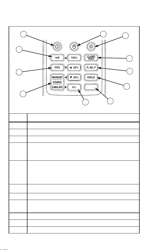
Getting Acquainted with the Meter
Figures 1-4 explain the Meter’s features, buttons, input/output jacks, and
display.
HART
2
7
3
4
5
6
Fjv06.eps
1
11
10
9
mA SCALELOOP PWR
mA IN/OUT
8
Number Description
A Turns the Meter on and off
B Measurement spotlight LED button
C Turns the display backlight on and off
Switches the Meter to Clamp Measure mode. Zeros the clamp
reading in Clamp mode. The Clamp modes includes clamp
D
measure, mA scale output, and mA IN/OUT.
Press N first to change to mA scale (773).
Cycles through source output ramping and 25 % stepping:
() Slow repeating 0 % - 100 % - 0 % ramp
E
() Fast repeating 0 % - 100 % - 0 % ramp
() Repeating 0 % - 100 % - 0 % ramp in 25 % steps
Press N first to activate mA IN/OUT (773).
Captures and holds the current reading. Pressing N first
F
activates the 250 Ω HART resistor.
G N activates features listed above some buttons
0 %-100 %- sets voltage or mA sourcing output. Press N first to
H
activate U, V, X, and W to adjust the source output. Long press
G or D to set span range point.
I Measure, Source, Simulate button
J DC Volts selection (773)
K mA selection. Press N first to activate Loop Power function.
Figure 1. Buttons
Page 5

4
1
773
MILLIAMP PROCESS
CLAMP METER
2
3
Fjv05.eps
Number Description
A Detachable clamp
Tactile Barrier docked and un-docked. Refer to “Safety Information
B
and Symbols”.
C Display
D Measurement spotlight LED
Figure 2. The Milliamp Process Clamp Meter
Page 6

3
4
2
1
17
5
6
7
8
16
15
MAX
14
13
12
9
10
11
Fjv07.eps
Number Description
A Main display values
B HOLD is activated
C Clamp is active
D Test lead jack indicator. Test lead connection is required.
E HART 250 Ω resistor is engaged
F Shift is active
G Reading is scaled
H Loop Power is active
I Milliamps
J Volts dc
K Percentage
L Secondary display
M Ramping is engaged
N Low battery symbol
O Maximum voltage warning
P High voltage is present
Q Measure, Source, or Simulate is active
Figure 3. Display (773 shown)
Page 7

773 772
4
3
2
1
5
4
Fjv04.eps
Number Description
Voltage measurement test lead input, also used for voltage
A
sourcing HI.
B Common test lead input, also used for voltage sourcing LO.
C -mA test lead input, also used for mA sourcing.
D +mA test lead input, also used for mA sourcing.
Common test lead input. -mA test lead input. Also used for mA
E
sourcing.
Figure 4. Input/Output Jacks
Features
The following sections give more detail about the Meter’s features.
Percentage Span
The Source and Simulate Percentage Span feature displays the span for
4 to 20 mA loops. Use G, F, E, and D to adjust the source
or simulated current (772) or dc voltage and current (773).
20 mA 100 % 8 mA 25 %
16 mA 75 % 4 mA 0 %
12 mA 50 % 0 mA -25 %
Zero Adjust
Before taking measurements with the clamp, push C to zero the
display by removing the offset. Make sure the clamp jaws are closed and
no current is flowing through them before zeroing.
Backlight
Press Q to turn the backlight on and off. The backlight automatically
turns off after 2 minutes.
Page 8

User Options
Several user options can be activated at Meter power up. Hold N
when powering on the Meter. While holding down N, toggle on/off
each option by repeatedly pressing the following keys:
• Q toggle on/off backlight auto off. Display shows bLit on or oFF.
• A toggle on/off spotlight auto off. Display shows SLit on or oFF.
• H toggle on/off auto power off. Display shows PoFF on or oFF.
When all key are released, the software version appears and the Meter
enters Clamp Measure mode.
Measurement Spotlight LED
The Measurement Spotlight LED helps to quickly find mA signal wires.
Press A to activate it. To extend battery life, the light automatically turns
off after 2 minutes.
Display HOLD
XW Warning
To avoid electric shock, be aware of the measurement
being taken when using Display HOLD. When Display
HOLD is activated, the display will not change when
different currents are applied.
Press H to activate Display Hold mode. The display shows I and
the display freezes. To exit and return to normal operation, press H a
second time. When in Auto Ramping mode, H stops ramping.
Auto Ramping the Output
Auto ramping can continuously apply a varying output from the mA
source to a device while your hands remain free to test the response.
When K is pressed, the Meter produces a repeating 0 % - 100 % 0 % ramp in a choice of three ramp waveforms:
• () 0 % - 100 % - 0 % 40-second smooth ramp
• () 0 % - 100 % - 0 % 30-second smooth ramp
• () 0 % - 100 % - 0 % 25 % step ramp, 10 seconds each step.
To exit ramping, press any button.
Probe Holder
The Meter is equipped with a probe holder that can either hold a test
probe or can be used to attach the Fluke ToolPak. See Figure 5.
Figure 5. The Probe Holder
Fjv08.eps
Page 9

Taking Measurements
XW Warning
To avoid electric shock, do not use the clamp on noninsulated conductors.
Measurements can be taken with the clamp in the docked position,
remotely using the 1 m cable, or via test leads. For accurate
measurements:
• Always zero the Meter prior to taking measurements with the clamp.
• To reduce magnetic influences, zero the Meter as close to the
measurement in the same position or jaw direction that is used for
the measurements as possible.
• Make sure the clamp is free of contamination.
To use the clamp for measurements:
1. Press C to enter Clamp Measure mode and to zero the Meter.
Clamp mode includes clamp measure, mA scale output, and mA
IN/OUT. If necessary, press N to change to mA scale.
2. Clamp the jaw around the conductor under test. The Meter displays
the measured conductor current. See Figure 6.
• A positive reading indicates current flowing in the direction of
the arrow on the clamp.
• A negative reading indicates current flowing in the opposite
direction of the arrow.
• Do not clamp more than one wire.
The small secondary display shows the reading in mA percentage of
span.
Figure 6. Taking Measurements with the Clamp
OK
fjv03.eps
Page 10

To use the test leads for measurements:
1. Insert the test leads into the proper input jacks. See Figure 7.
2. Press the correct button for the measurement.
3. Apply the test leads.
4. Observe the reading on the main display. In mA mode, the
secondary display shows the reading in percentage of span.
mA SCALELOOP PWR
mA IN/OUT
HART
fjv09.eps
Figure 7. Taking Measurements with the Test Leads
Current and Voltage Output Functions
Both Meters provide steady, stepped, and ramped current output for
testing 0-24 mA current loops. Additionally, the 773 provides voltage
output to 10 V. To access these functions, press
• Choose Source mode to supply current or voltage.
• Choose Simulate mode to regulate current in an externally powered
current loop.
• Choose Loop Supply mode to power an external device and
measure mA loop current.
T as necessary.
Sourcing mA
Use mA Source mode whenever it is necessary to source current into a
passive circuit such as a current loop with no loop supply. Source mode
depletes the battery faster than Simulate mode.
To enter Source mode for the 772, see Figure 4:
1. Insert the test leads into the -mA and +mA jacks.
2. Press L.
3. Press
T until Source appears on the display.
Page 11

To enter mA Source mode for the 773, see Figure 8:
1. Insert the test leads into the desired input jacks.
2. Press L.
3. Press
T until Source appears on the display.
Figure 8. Sourcing mA Output
Simulating mA Output
In Simulate mode, the Meter simulates a current loop transmitter. To
enter Simulate mode, see Figure 9:
1. Insert the test leads into the mA+ and mA- input jacks.
2. Press L.
3. Press
T until Simulate appears on the display.
Fjv10.eps
Page 12

+
Fjv11.eps
Figure 9. Simulating mA Output
Loop Supply
In Loop Supply mode, the Meter powers a transmitter while measuring
the mA signal. To enter Loop Supply mode, see Figure 10:
1. Insert the test leads into the LOOP PWR jacks. See Figure 10.
2. Press N.
3. Press L.
The Meter is now in Loop Supply mode.
Figure 10. Using Loop Supply Mode
Fjv13.eps
Page 13

Maintenance
XW Warning
To avoid possible electric shock or personal injury, repairs
or servicing not covered in this manual should be
performed only by qualified personnel.
Cleaning the Meter
XW Warning
To avoid electrical shock, remove any input signals before
cleaning.
W Caution
To avoid damaging the Meter, do not use aromatic
hydrocarbons or chlorinated solvents for cleaning. These
solutions will react with the plastics used in the Meter.
Clean the instrument case with a damp cloth and mild detergent.
Battery Replacement
XW Warning
To avoid false readings, that could lead to possible electric
shock or personal injury, replace the batteries as soon as
the low battery indicator (B) appears.
To replace the batteries, see Figure 10:
1. Turn the Meter off.
2. Use a flat head screwdriver to loosen the battery compartment door
screw, and remove the door from the case bottom.
3. Remove the batteries.
4. Replace the batteries with four new AA batteries.
5. Reattach the battery compartment door to the case bottom and tighten
the screw.
Figure 11. Changing the Batteries
fjv02.eps
Page 14

Specifications
Electrical Specifications
Current Measurement
With Jaw
Ranges ................................ 0-20.99 mA; 21-100 mA
Resolution............................ 0.01 mA; 0.1 mA
Accuracy.............................. 0.2 % + 5 counts;1 % + 5 counts
In Circuit
Range .................................. 0-24 mA
Resolution............................ 0.01 mA
Accuracy.............................. 0.2 % + 2 counts
Current Source
Range .................................. 0-24 mA
Resolution............................ 0.01 mA
Accuracy.............................. 0.2 % + 2 counts
mA Drive.............................. 24 mA into 1000 Ω
Current Simulate
Range .................................. 0-24 mA
Resolution............................ 0.01 mA
Accuracy.............................. 0.2 % + 2 counts
Maximum Voltage................ 50 V
DC Voltage Measurement (773)
Range .................................. 0-30 V
Resolution............................ 0.01 V
Accuracy.............................. 0.2 % + 2 counts
DC voltage source (773)
Range .................................. 0-10 V
Resolution............................ 0.01 V
Accuracy.............................. 0.2 % + 2 counts
mA Drive.............................. 2 mA max all conditions
mA IN/OUT (773)
Sourcing range ....................0-24 mA
Sourcing resolution.............. 0.01 mA
Sourcing accuracy ............... 0.2 % + 2 counts
Measurement range.............0-24 mA
Measurement resolution ...... 0.01 mA
Measurement accuracy .......1 % FS
Scaled mA current output to mA current input from the Jaw (773)
Range .................................. 0-24 mA
Resolution............................ 0.01 mA
Accuracy.............................. 1 % FS
Response speed ........................ 2 times per second
DC Loop Power.......................... 24 V
Influence of Earth’s Field............<0.20 mA
Batteries..................................... 4 1.5 V, Alkaline , IEC LR6
Working hours............................ 12 hours @ 12 mA sourced into 500 Ω
Mechanical Specifications
Size (H X W X L) ....................... 43.7 mm x 70 mm x 246.2 mm
Weight........................................ 410 g
Page 15

Environmental Specifications
Operating Temperature .............-10 ~50 °C
Storage Temperature.................-25 ~60 °C
Operating Humidity.................... <90 % RH @ <30 °C ;<75 % RH @ 30 ~50 °C
Operating Altitude...................... 0 ~ 2000 m
IP Rating.................................... IP 40
Vibration Requirements ............. Random 2 g, 5 to 500 Hz
Drop Test Requirements............1 meter drop test (except the jaw)
EMI, RFI, EMC...........................Meets all applicable requirements in
Temperature Coefficients ..........0.1(/ °C X Specified accuracy for
EN61326-1
Note: For current measurement w/jaw, add
1 mA to specification for EMC field strengths
of 1 V/m up to 3 V/m.
Temperature <18 °C or > 28 °C)
Standards and Agency Approval Specifications
All products certified to the following:
EN / IEC 61010-1, EN / IEC 61010-2-032
Agency Approvals P, ), ;
Miscellaneous Specifications
Power Requirements..................Four AA batteries, Alkaline , IEC LR6
Automatic Time-out (Power).......After 15 minutes ±1 minutes
Automatic Time-out (Backlight)..After 2 minutes ±10 seconds
Automatic Time-out
(Measurement Spotlight)............After 2 minutes ±10 seconds
Page 16

User Replaceable Parts
Table 2 lists all user replaceable parts.
Table 2. Replaceable Parts
Part or Model
Number
376756 AA Batteries, 1.5 V 4
3369914 Absorber 1
3350978 Battery door 1
948609 Fastener 2
3351060 Soft Carrying Case 1
3351049 Instruction Sheet 1
3362376 Service Information Sheet 1
1616705 TL940 Mini Hook with Test Lead 1 Set
855742 TL75- Test Leads 1 Set
1670095 AC72 Detachable Clip 2
3031302 Velcro Strip 1
669967 TPAK, Strap 17 inches 1
337574 Hanger 1
Replacement clamp and cable assembly are available but require recalibration. See the 772/773 Service Information Sheet for part numbers
and procedures.
LIMITED WARRANTY & LIMITATION OF LIABILITY
This Fluke product will be free from defects in material and workmanship
for 3 years (one year for cable and clamp) from the date of purchase.
This warranty does not cover fuses, disposable batteries or damage from
accident, neglect, misuse or abnormal conditions of operation or handling.
Resellers are not authorized to extend any other warranty on Fluke’s
behalf. To obtain service during the warranty period, send your defective
product to the nearest Fluke Authorized Service Center with a description
of the problem.
THIS WARRANTY IS YOUR ONLY REMEDY. NO OTHER
WARRANTIES, SUCH AS FITNESS FOR A PARTICULAR PURPOSE,
ARE EXPRESSED OR IMPLIED. FLUKE IS NOT LIABLE FOR ANY
SPECIAL, INDIRECT, INCIDENTAL OR CONSEQUENTIAL DAMAGES
OR LOSSES, ARISING FROM ANY CAUSE OR THEORY. Since some
states or countries do not allow the exclusion or limitation of an implied
warranty or of incidental or consequential damages, this limitation of
liability may not apply to you.
Fluke Corporation
P.O. Box 9090
Everett, WA 98206-9090
U.S.A.
Description Quantity
Fluke Europe B.V.
P.O. Box 1186
5602 BD Eindhoven
The Netherlands
 Loading...