

Page 1

5500A
®
Multi-Product Calibrator
Operator Manual
December 1994, Rev.11, 7/06
© 1994 - 2006 Fluke Corporation. All rights reserved. Printed in U.S.A.
All product names are trademarks of their respective companies.
Page 2

LIMITED WARRANTY & LIMITATION OF LIABILITY
Each Fluke product is warranted to be free from defects in material and workmanship under
normal use and service. The warranty period is one year and begins on the date of shipment.
Parts, product repairs and services are warranted for 90 days. This warranty extends only to the
original buyer or end-user customer of a Fluke authorized reseller, and does not apply to fuses,
disposable batteries or to any product which, in Fluke's opinion, has been misused, altered,
neglected or damaged by accident or abnormal conditions of operation or handling. Fluke
warrants that software will operate substantially in accordance with its functional specifications
for 90 days and that it has been properly recorded on non-defective media. Fluke does not
warrant that software will be error free or operate without interruption.
Fluke authorized resellers shall extend this warranty on new and unused products to end-user
customers only but have no authority to extend a greater or different warranty on behalf of
Fluke. Warranty support is available if product is purchased through a Fluke authorized sales
outlet or Buyer has paid the applicable international price. Fluke reserves the right to invoice
Buyer for importation costs of repair/replacement parts when product purchased in one country
is submitted for repair in another country.
Fluke's warranty obligation is limited, at Fluke's option, to refund of the purchase price, free of
charge repair, or replacement of a defective product which is returned to a Fluke authorized
service center within the warranty period.
To obtain warranty service, contact your nearest Fluke authorized service center or send the
product, with a description of the difficulty, postage and insurance prepaid (FOB Destination), to
the nearest Fluke authorized service center. Fluke assumes no risk for damage in transit.
Following warranty repair, the product will be returned to Buyer, transportation prepaid (FOB
Destination). If Fluke determines that the failure was caused by misuse, alteration, accident or
abnormal condition of operation or handling, Fluke will provide an estimate of repair costs and
obtain authorization before commencing the work. Following repair, the product will be returned
to the Buyer transportation prepaid and the Buyer will be billed for the repair and return
transportation charges (FOB Shipping Point).
THIS WARRANTY IS BUYER'S SOLE AND EXCLUSIVE REMEDY AND IS IN LIEU OF ALL
OTHER WARRANTIES, EXPRESS OR IMPLIED, INCLUDING BUT NOT LIMITED TO ANY
IMPLIED WARRANTY OF MERCHANTABILITY OR FITNESS FOR A PARTICULAR
PURPOSE. FLUKE SHALL NOT BE LIABLE FOR ANY SPECIAL, INDIRECT, INCIDENTAL
OR CONSEQUENTIAL DAMAGES OR LOSSES, INCLUDING LOSS OF DATA, WHETHER
ARISING FROM BREACH OF WARRANTY OR BASED ON CONTRACT, TORT, RELIANCE
OR ANY OTHER THEORY.
Since some countries or states do not allow limitation of the term of an implied warranty, or
exclusion or limitation of incidental or consequential damages, the limitations and exclusions of
this warranty may not apply to every buyer. If any provision of this Warranty is held invalid or
unenforceable by a court of competent jurisdiction, such holding will not affect the validity or
enforceability of any other provision.
Fluke Corporation Fluke Europe B.V.
P.O. Box 9090 P.O. Box 1186
Everett, WA 98206-9090 5602 BD Eindhoven
U.S.A. The Netherlands
5/94
Page 3

LIMITE DE GARANTIE ET LIMITE DE RESPONSABILITE
La société Fluke garantit l'absence de vices des matériaux et à la fabrication de ce produit dans
des conditions normales d'utilisation et d'entretien. La période de garantie est de un an et prend
effet à la date d'expédition. Les pièces, les réparations de produit et les services sont garantis
pour un période de 90 jours. Cette garantie ne s'applique qu'à l'acheteur d'origine ou à l'utilisateur
final s'il est client d'un distributeur agréé par Fluke, et ne s'applique pas aux fusibles, aux
batteries/piles interchangeables ni à aucun produit qui, de l'avis de Fluke, a été malmené, modifié,
négligé ou endommagé par accident ou soumis à des conditions anormales d'utilisation et de
manipulation. Fluke garantit que le logiciel fonctionnera en grande partie conformément à ses
spécifications fonctionnelles pour une période de 90 jours et qu'il a été correctement enregistré sur
des supports non défectueux. Fluke ne garantit pas que le logiciel ne contient pas d'erreurs ou
qu'il fonctionne sans interruption.
Les distributeurs agréés par Fluke appliqueront cette garantie à des produits vendus à leurs
clients neufs et qui n'ont pas servi mais ne sont pas autorisés à appliquer une garantie plus
étendue ou différente au nom de Fluke. Le support de garantie est offert si le produit a été acquis
par l'intermédiaire d'un point de vente agréé par Fluke ou bien si l'acheteur a payé le prix
international applicable. Fluke se réserve le droit de facturer à l'acheteur les frais d'importation des
pièces de réparation ou de remplacement si le produit acheté dans un pays a été expédié dans un
autre pays pour y être réparé.
L'obligation de garantie de Fluke est limitée, au choix de Fluke, au remboursement du prix d'achat,
ou à la réparation/remplacement gratuit d'un produit défectueux retourné dans le délai de garantie
à un centre de service agréé par Fluke.
Pour avoir recours au service de la garantie, mettez-vous en rapport avec le centre de service
Fluke le plus proche ou envoyez le produit, accompagné d'une description du problème, port et
assurance payés (franco lieu de destination), au centre de service agréé par Fluke le plus proche.
Fluke dégage toute responsabilité en cas de dégradations survenues au cours du transport. Après
la réparation sous garantie, le produit sera retourné à l'acheteur, frais de port payés d'avance
(franco lieu de destination). Si Fluke estime que le problème a été causé par un traitement abusif,
une modification, un accident ou des conditions de fonctionnement ou de manipulation anormales,
Fluke fournira un devis des frais de réparation et ne commencera la réparation qu'après en avoir
reçu l'autorisation. Après la réparation, le produit sera retourné à l'acheteur, frais de port payés
d'avance, et les frais de réparation et de transport lui seront facturés.
LA PRESENTE GARANTIE EST EXCLUSIVE ET TIENT LIEU DE TOUTES AUTRES
GARANTIES, EXPLICITES OU IMPLICITES, Y COMPRIS, MAIS NON EXCLUSIVEMENT,
TOUTE GARANTIE IMPLICITE QUANT A L'APTITUDE DU PRODUIT A ETRE COMMERCIALISE
OU A ETRE APPLIQUE A UNE FIN OU A UN USAGE DETERMINE. FLUKE NE POURRA ETRE
TENU RESPONSABLE D'AUCUN DOMMAGE PARTICULIER, INDIRECT, ACCIDENTEL OU
CONSECUTIF, NI D'AUCUNS DEGATS OU PERTES DE DONNEES, QUE CE SOIT A LA SUITE
D'UNE INFRACTION AUX OBLIGATIONS DE GARANTIE, SUR UNE BASE CONTRACTUELLE,
EXTRA- CONTRACTUELLE OU AUTRE.
Etant donné que certains pays ou états n'admettent pas les limitations d'une condition de garantie
implicite, ou l'exclusion ou la limitation de dégâts accidentels ou consécutifs, les limitations et les
exclusions de cette garantie pourraient ne pas s'appliquer à chaque acheteur. Si une disposition
quelconque de cette garantie est jugée non valide ou inapplicable par un tribunal compétent, une
telle décision n'affectera en rien la validité ou le caractère exécutoire de toute autre disposition.
Fluke Corporation Fluke Europe B.V.
P.O. Box 9090 P.O. Box 1186
Everett, WA 98206-9090 5602 B.D. Eindhoven
USA Pays-Bas
Page 4

BEFRISTETE GARANTIEBESTIMMUNGEN & HAFTUNGSBESCHRÄNKUNG
Für jedes Produkt, das Fluke herstellt, leistet Fluke eine Garantie für einwandfreie Materialqualitßt und fehlerfreie
Ausführung unter normalen Betriebs- und Wartungsbedingungen. Der Garantiezeitraum gilt für ein Jahr und beginnt
mit dem Lieferdatum. Die Garantiebestimmungen für Ersatzteile, Instandsetzungs- und Wartungsarbeiten gelten für
einen Zeitraum von 90 Tagen. Diese Garantie wird ausschließlich dem Ersterwerber bzw. dem Endverbraucher, der
das betreffende Produkt von einer von Fluke autorisierten Weiterverkaufsstelle erworben hat, geleistet und erstreckt
sich nicht auf Sicherungen, Einwegbatterien oder irgendwelche andere Produkte, die nach dem Ermessen von
Fluke unsachgemäß verwendet, verändert, vernachlässigt, durch Unfälle beschädigt oder abnormalen
Betriebsbedingungen oder einer unsachgemäßen Handhabung ausgesetzt wurden. Fluke garantiert für einen
Zeitraum von 90 Tagen, daß die Software im wesentlichen in Übereinstimmung mit den einschlägigen
Funktionsbeschreibungen funktioniert und daß diese Software auf fehlerfreien Datenträgern gespeichert wurde.
Fluke übernimmt jedoch keine Garantie dafür, daß die Software fehlerfrei ist und störungsfrei arbeitet.
Von Fluke autorisierte Weiterverkaufsstellen werden diese Garantie ausschließlich für neue und nichtbenutzte, an
Endverbraucher verkaufte Produkte leisten, sind jedoch nicht dazu berechtigt, diese Garantie im Namen von Fluke
zu verlängern, auszudehnen oder in irgendeiner anderen Weise abzuändern. Der Erwerber hat das Recht aus der
Garantie abgeleitete Unterstützungsleistungen in Anspruch zu nehmen, wenn er das Produkt bei einer von Fluke
autorisierten Vertriebsstelle gekauft oder den jeweils geltenden internationalen Preis gezahlt hat. Fluke behält sich
das Recht vor, dem Erwerber Einfuhrgebühren für Ersatzteile in Rechnung zu stellen, wenn dieser das Produkt in
einem anderen Land zur Reparatur anbietet, als das Land, in dem er das Produkt ursprünglich erworben hat.
Flukes Garantieverpflichtung beschränkt sich darauf, daß Fluke nach eigenem Ermessen den Kaufpreis ersetzt oder
aber das defekte Produkt unentgeltlich repariert oder austauscht, wenn dieses Produkt innerhalb der Garantiefrist
einem von Fluke autorisierten Servicezentrum zur Reparatur übergeben wird.
Um die Garantieleistung in Anspruch zu nehmen, wenden Sie sich bitte an das nächstgelegene und von Fluke
autorisierte Servicezentrum oder senden Sie das Produkt mit einer Beschreibung des Problems und unter
Vorauszahlung von Fracht- und Versicherungskosten (FOB Bestimmungsort) an das nächstgelegene und von Fluke
autorisierte Servicezentrum. Fluke übernimmt keinerlei Haftung für eventuelle Transportschäden. Im Anschluß an
die Reparatur wird das Produkt unter Vorauszahlung von Frachtkosten (FOB Bestimmungsort) an den Erwerber
zurückgesandt. Wenn Fluke jedoch feststellt, daß der Defekt auf unsachgemäße Handhabung, Veränderungen am
Gerät, einen Unfall oder auf anormale Betriebsbedingungen oder unsachgemäße Handhabung zurückzuführen ist,
wird Fluke dem Erwerber einen Voranschlag der Reparaturkosten zukommen lassen und erst die Zustimmung des
Erwerbers einholen, bevor die Arbeiten in Angriff genommen werden. Nach der Reparatur wird das Produkt unter
Vorauszahlung der Frachtkosten an den Erwerber zurückgeschickt und werden dem Erwerber die Reparaturkosten
und die Versandkosten (FOB Versandort) in Rechnung gestellt.
DIE VORSTEHENDEN GARANTIEBESTIMMUNGEN SIND DAS EINZIGE UND ALLEINIGE RECHT AUF
SCHADENERSATZ DES ERWERBERS UND GELTEN AUSSCHLIESSLICH UND AN STELLE VON ALLEN
ANDEREN VERTRAGLICHEN ODER GESETZLICHEN GEWÄHRLEISTUNGSPFLICHTEN, EINSCHLIESSLICH JEDOCH NICHT DARAUF BESCHRÄNKT - DER GESETZLICHEN GEWÄHRLEISTUNG DER
MARKTFÄHIGKEIT, DER GEBRAUCHSEIGNUNG UND DER ZWECKDIENLICHKEIT FÜR EINEN BESTIMMTEN
EINSATZ. FLUKE ÜBERNIMMT KEINE HAFTUNG FÜR SPEZIELLE, UNMITTELBARE, MITTELBARE, BEGLEITODER FOLGESCHÄDEN ODER ABER VERLUSTE, EINSCHLIESSLICH DES VERLUSTS VON DATEN,
UNABHÄNGIG DAVON, OB SIE AUF VERLETZUNG DER GEWÄHRLEISTUNGSPFLICHT, RECHTMÄSSIGE,
UNRECHTMÄSSIGE ODER ANDERE HANDLUNGEN ZURÜCKZUFÜHREN SIND.
Angesichts der Tatsache, daß in einigen Ländern die Begrenzung einer gesetzlichen Gewährleistung sowie der
Ausschluß oder die Begrenzung von Begleit- oder Folgeschäden nicht zulässig ist, könnte es sein, daß die
obengenannten Einschränkungen und Ausschlüsse nicht für jeden Erwerber gelten. Sollte irgendeine Klausel dieser
Garantiebestimmungen von einem zuständigen Gericht für unwirksam oder nicht durchsetzbar befunden werden, so
bleiben die Wirksamkeit oder Erzwingbarkeit irgendeiner anderen Klausel dieser Garantiebestimmungen von einem
solchen Spruch unberührt.
Fluke Corporation Fluke Europe B.V.
Postfach 9090 Postfach 1186
Everett, WA 98206-9090 5602 B.D. Eindhoven
USA Niederlande
Page 5

GARANTÍA LIMITADA Y LIMITACIÓN DE RESPONSABILIDAD
Se garantiza que cada uno de los productos de Fluke no tiene defectos de material y mano de
obra si es objeto de una utilización y un mantenimiento normales. El período de garantía es de
un año y comienza a partir de la fecha de envío. Las piezas, reparaciones y mantenimiento del
producto están garantizados durante 90 días. Esta garantía se concede exclusivamente al
comprador original o al cliente usuario final de un revendedor autorizado por Fluke, y no es de
aplicación a fusibles, baterías o pilas desechables o cualquier otro producto que, en opinión de
Fluke, haya sido objeto de una mala utilización, alteración, negligencia o daños por accidente o
manejo o manipulación anómalos. Fluke garantiza que el software operará sustancialmente de
acuerdo con sus especificaciones funcionales durante 90 días y que ha sido grabado
correctamente en medios no defectuosos. Fluke no garantiza que el software carezca de
errores ni opere sin interrupción.
Los revendedores autorizados por Fluke concederán esta garantía a productos nuevos y sin
utilizar suministrados a clientes usuarios finales exclusivamente, pero no tienen autoridad para
conceder una garantía diferente o mayor por cuenta de Fluke. Puede utilizar el servicio de
garantía si el producto ha si do comprado en una oficina de ventas Fluke autorizada o si el
Comprador ha pagado el importe de aplicación internacional. Fluke se reserva el derecho de
facturar al Comprador los costes de importación debidos a la reparación o sustitución de piezas
cuando el producto comprado en un país es enviado para su reparación a otro país.
La obligación de Fluke en concepto de garantía se limita, a criterio de Fluke, al reembolso del
importe de la compra, a la reparación gratis, o a la sustitución de un producto defectuoso que
sea devuelto a un centro de servicio Fluke autorizado dentro del período de garantía.
Para obtener servicio en garantía, póngase en contacto con el Servicio Oficial Fluke autorizado
más próximo o envíe el producto, con una descripción del problema surgido, a portes y seguros
pagados por anticipado (FOB en Destino), al Servicio Oficial Fluke autorizado más próximo.
Fluke no asume ningún riesgo por los daños en tránsito. Tras la reparación en concepto de
garantía, el producto será devuelto al Comprador, previo pago del transporte (FOB en Destino).
Si Fluke decide que la avería ha sido causada por una mala utilización, alteración, accidente o
manejo o manipulación anormales, Fluke hará una estimación de los costes de reparación y
solicitará autorización antes de comenzar el trabajo. Tras la reparación, el producto será
devuelto al Comprador, previo pago del transporte, y se facturarán al Comprador los gastos en
concepto de reparación y de transporte para su devolución (FOB en el Punto de envío).
ESTA GARANTÍA SE CONCEDE A TÍTULO ÚNICO Y EXCLUSIVO DEL COMPRADOR Y
SUSTITUYE A TODAS LAS DEMÁS GARANTÍAS, EXPRESAS O IMPLÍCITAS, INCLUYENDO,
PERO SIN LIMITARSE A, NINGUNA GARANTÍA IMPLÍCITA DE COMERCIABILIDAD O
IDONEIDAD PARA UN FIN O UN USO DETERMINADOS. FLUKE NO SE
RESPONSABILIZARÁ DE PÉRDIDAS O DAÑOS ESPECIALES, INDIRECTOS, IMPREVISTOS
O CONTINGENTES, INCLUIDA LA PÉRDIDA DE DATOS, YA SEAN PRODUCTO DE
VIOLACIÓN DE LA GARANTÍA O YA SEA EN RELACIÓN CON UN CONTRATO, POR
RESPONSABILIDAD CIVIL EXTRACONTRACTUAL, CONFIANZA O EN CUALQUIER OTRA
FORMA.
Dado que algunos países o estados no permiten la limitación del plazo de una garantía
implícita, ni la exclusión o limitación de daños imprevistos o contingentes, las limitaciones y
exclusiones de esta garantía pueden no ser de aplicación a todos los compradores. Si alguna
disposición de esta Garantía es considerada nula o no aplicable por un tribunal de justicia
competente, dicha consideración no afectará a la validez o aplicación de las demás
disposiciones.
Fluke Corporation Fluke Europe B.V.
P.O. Box 9090 P.O. Box 1186
Everett, WA 98206-9090 5602 B.D. Eindhoven
ESTADOS UNIDOS Holanda
Page 6

W CAUTION
This is an IEC safety Class 1 product. Before using, the ground wire in the
line cord or rear panel binding post must be connected to an earth ground
for safety.
Interference Information
This equipment generates and uses radio frequency energy and if not installed and used in
strict accordance with the manufacturer’s instructions, may cause interference to radio and
television reception. It has been type tested and found to comply with the limits for a Class B
computing device in accordance with the specifications of Part 15 of FCC Rules, which are
designed to provide reasonable protection against such interference in a residential installation.
Operation is subject to the following two conditions:
• This device may not cause harmful interference.
• This device must accept any interference received, including interference that may cause
undesired operation.
There is no guarantee that interference will not occur in a particular installation. If this equipment
does cause interference to radio or television reception, which can be determined by turning the
equipment off and on, the user is encouraged to try to correct the interference by one of more of
the following measures:
• Reorient the receiving antenna
• Relocate the equipment with respect to the receiver
• Move the equipment away from the receiver
• Plug the equipment into a different outlet so that the computer and receiver are on different
branch circuits
If necessary, the user should consult the dealer or an experienced radio/television technician for
additional suggestions. The user may find the following booklet prepared by the Federal
Communications Commission helpful: How to Identify and Resolve Radio-TV Interference
Problems. This booklet is available from the U.S. Government Printing Office, Washington, D.C.
20402. Stock No. 004-000-00345-4.
Declaration of the Manufacturer or Importer
We hereby certify that the Fluke Model 5500A is in compliance with BMPT Vfg 243/1991 and is
RFI suppressed. The normal operation of some equipment (e.g. signal generators) may be
subject to specific restrictions. Please observe the notices in the users manual. The marketing
and sales of the equipment was reported to the Central Office for Telecommunication Permits
(BZT). The right to retest this equipment to verify compliance with the regulation was given to
the BZT.
Bescheinigung des Herstellers/Importeurs
Hiermit wird bescheinigt, daβ die Fluke Model 5500A in Übereinstimmung mit den
Bestimmungen der BMPT-AmtsblVfg 243/1991 funk-entstört sind. Der vorschriftsmäßige
Betrieb mancher Geräte (z.B. Meßsender) kann allerdings gewissen Einschränkungen
unterliegen. Beachten Sie deshalb die Hinweise in der Bedienungsanleitung. Dem Bundesamt
für Zulassungen in der Telecommunikation wurde das Inverkehrbringen dieses Gerätes
angezeigt und die Berechtigung zur Überprüfung der Serie auf Einhaltung der Bestimmungen
eingeräumt.
Fluke Corporation
Page 7

SAFETY TERMS IN THIS MANUAL
This instrument has been designed and tested in accordance with IEC publication
1010-1 (1992-1), Safety Requirements for Electrical Measuring, Control and Laboratory
Equipment, and ANSI/ISA-582.01-1994, and CAN/CSA-C22.2 No. 1010.1-92. This User
Manual contains information, warning, and cautions that must be followed to ensure safe
operation and to maintain the instrument in a safe condition. Use of this equipment in a
manner not specified herein may impair the protection provided by the equipment.
This instrument is designed for IEC 1010-1 Installation Category II use. It is not designed
for connection to circuits rated over 4800 VA.
WARNING statements identify conditions or practices that could result in personal injury
or loss of life.
CAUTION statements identify conditions or practices that could result in damage to
equipment.
SYMBOLS MARKED ON EQUIPMENT
WARNING
references).
Risk of electric shock. Refer to the manual (see the Index for
GROUND Ground terminal to chassis (earth).
Attention Refer to the manual (see the Index for references). This
symbol indicates that information about usage of a feature is contained in
the manual. This symbol appears on the rear panel ground post and by
the fuse compartment.
AC POWER SOURCE
The instrument is intended to operate from an ac power source that will not apply more
than 264V ac rms between the supply conductors or between either supply conductor
and ground. A protective ground connection by way of the grounding conductor in the
power cord is required for safe operation.
USE THE PROPER FUSE
To avoid fire hazard, for fuse replacement use only the specified unit: 110 or 120 V
operation, 2.5 ampere/250 volt time delay; 220 or 240 V operation, 1.25 ampere/250 volt
time delay.
GROUNDING THE INSTRUMENT
The instrument utilizes controlled overvoltage techniques that require the instrument to
be grounded whenever normal mode or common mode ac voltages or transient voltages
may occur. The enclosure must be grounded through the grounding conductor of the
power cord, or through the rear panel ground binding post.
Page 8

USE THE PROPER POWER CORD
Use only the power cord and connector appropriate for the voltage and plug
configuration in your country.
Use only a power cord that is in good condition.
Refer power cord and connector changes to qualified service personnel.
DO NOT OPERATE IN EXPLOSIVE ATMOSPHERES
To avoid explosion, do not operate the instrument in an atmosphere of explosive gas.
DO NOT REMOVE COVER DURING OPERATION
To avoid personal injury or death, do not remove the instrument cover without first
removing the power source connected to the rear panel. Do not operate the instrument
without the cover properly installed. Normal calibration is accomplished with the cover
closed. Access procedures and the warnings for such procedures are contained both in
this manual and in the Service Manual. Service procedures are for qualified service
personnel only.
DO NOT ATTEMPT TO OPERATE IF PROTECTION MAY BE IMPAIRED
If the instrument appears damaged or operates abnormally, protection may be impaired.
Do not attempt to operate the instrument under these conditions. Refer all questions of
proper instrument operation to qualified service personnel.
Page 9

Table of Contents
Chapter Contents Page
1 Introduction and Specifications......................................................... 1-1
1-1.
Introduction........................................................................................... 1-3
1-2. How to Contact Fluke........................................................................... 1-4
1-3. Operation Overview.............................................................................. 1-4
1-4. Local Operation................................................................................ 1-4
1-5. Remote Operation (RS-232)............................................................. 1-4
1-6. Remote Operation (IEEE-488) ......................................................... 1-5
1-7. Where To Go from Here....................................................................... 1-6
1-8. Instruction Manuals .............................................................................. 1-6
1-9. 5500A Operator Manual................................................................... 1-6
1-10. 5500A Operator Reference Guide .................................................... 1-7
1-11. 5500A Remote Programming Reference Guide............................... 1-7
1-12. 5500A Service Manual ..................................................................... 1-7
1-13. 5725A Amplifier................................................................................... 1-7
1-14. Specifications........................................................................................ 1-9
1-15. General Specifications.......................................................................... 1-10
1-16. DC Voltage Specifications ............................................................... 1-11
1-17. DC Current Specifications................................................................ 1-12
1-18. Resistance Specifications ................................................................. 1-13
1-19. AC Voltage (Sine Wave) Specifications .......................................... 1-14
1-20. AC Current (Sine Wave) Specifications........................................... 1-17
1-21. Capacitance Specifications............................................................... 1-19
1-22. Temperature Calibration (Thermocouple) Specifications ................ 1-20
1-23. Temperature Calibration (RTD) Specifications................................ 1-21
1-24. DC Power Specification Summary................................................... 1-22
1-25. AC Power (45 Hz to 65 Hz) Specification Summary, PF=1 ............ 1-22
1-26. Power and Dual Output Limit Specifications................................... 1-23
1-27. Phase Specifications ......................................................................... 1-24
1-28. Calculating Power Uncertainty......................................................... 1-25
i
Page 10

5500A
Operator Manual
1-29. Additional Specifications...................................................................... 1-26
1-30. Frequency Specifications.................................................................. 1-26
1-31. Harmonics (2nd to 50th) Specifications.............................................. 1-26
1-32. AC Voltage (Sine Wave) Extended Bandwidth Specifications........ 1-27
1-33. AC Voltage (Non-Sine Wave) Specifications .................................. 1-28
1-34. AC Voltage, DC Offset Specifications............................................. 1-29
1-35. AC Voltage, Square Wave Characteristics....................................... 1-29
1-36. AC Voltage, Triangle Wave Characteristics (typical)...................... 1-29
1-37. AC Current (Sine Wave) Extended Bandwidth Specifications ........ 1-29
1-38. AC Current (Non-Sinewave) Specifications .................................... 1-30
1-39. AC Current (Non-Sinewave) Specifications (cont).......................... 1-31
1-40. AC Current, Square Wave Characteristics (typical)......................... 1-31
1-41. AC Current, Triangle Wave Characteristics (typical) ...................... 1-31
2 Preparing for Operation...................................................................... 2-1
2-1. Introduction........................................................................................... 2-3
2-2. Unpacking and Inspection .................................................................... 2-3
2-3. Replacing The Fuse .............................................................................. 2-3
2-4. Selecting Line Voltage.......................................................................... 2-4
2-5. Connecting To Line Power ................................................................... 2-4
2-6. Service Information .............................................................................. 2-6
2-7. Placement and Rack Mounting ............................................................. 2-7
2-8. Cooling Considerations......................................................................... 2-7
2-9. Connecting the 5725A Amplifier ......................................................... 2-7
3 Features ............................................................................................... 3-1
3-1. Introduction........................................................................................... 3-3
3-2. Front Panel Features ............................................................................. 3-3
3-3. Rear Panel Features .............................................................................. 3-3
3-4. Softkey Menu Trees.............................................................................. 3-3
4 Front Panel Operation......................................................................... 4-1
4-1. Introduction........................................................................................... 4-3
4-2. Turning on the Calibrator ..................................................................... 4-3
4-3. Warming up the Calibrator ................................................................... 4-4
4-4. Using the Softkeys................................................................................ 4-4
4-5. Using the Setup Menu........................................................................... 4-4
4-6. Using the Instrument Setup Menu.................................................... 4-5
4-7. Selecting an External Amplifier ....................................................... 4-5
4-8. Utility Functions Menu .................................................................... 4-6
4-9. Using the Format EEPROM Menu .............................................. 4-6
4-10. Resetting the Calibrator ........................................................................ 4-7
4-11. Zeroing the Calibrator........................................................................... 4-7
4-12. Using the Operate and Standby Modes................................................. 4-8
4-13. Connecting the Calibrator to a UUT..................................................... 4-9
4-14. Recommended Cable and Connector Types..................................... 4-9
4-15. When to Use EARTH....................................................................... 4-10
4-16. Four-Wire versus Two-Wire Connections ....................................... 4-10
4-17. Cable Connection Instructions ......................................................... 4-11
ii
Page 11

4-18. Rms Versus Peak-to-Peak Waveforms ................................................. 4-16
4-19. Auto Range Versus Locked Range....................................................... 4-17
4-20. Setting the Output................................................................................. 4-17
4-21. Setting DC Voltage Output .............................................................. 4-18
4-22. Setting AC Voltage Output .............................................................. 4-19
4-23. Setting DC Current Output............................................................... 4-21
4-24. Setting AC Current Output............................................................... 4-22
4-25. Setting DC Power Output................................................................. 4-24
4-26. Setting AC Power Output................................................................. 4-25
4-27. Setting a Dual DC Voltage Output................................................... 4-28
4-28. Setting a Dual AC Voltage Output................................................... 4-30
4-29. Setting Resistance Output................................................................. 4-32
4-30. Setting Capacitance Output .............................................................. 4-33
4-31. Setting Temperature Simulation (Thermocouple)............................ 4-35
4-32. Setting Temperature Simulation (RTD) ........................................... 4-37
4-33. Measuring Thermocouple Temperatures.......................................... 4-39
4-34. Waveform Types................................................................................... 4-40
4-35. Sinewave .......................................................................................... 4-41
4-36. Trianglewave .................................................................................... 4-41
4-37. Squarewave ...................................................................................... 4-41
4-38. Truncated Sinewave ......................................................................... 4-42
4-39. Setting Harmonics................................................................................. 4-42
4-40. Adjusting the Phase .............................................................................. 4-43
4-41. Entering a Phase Angle .................................................................... 4-44
4-42. Entering a Power Factor ................................................................... 4-45
4-43. Entering a DC Offset ............................................................................ 4-46
4-44. Using the 5725A Amplifier .................................................................. 4-47
4-45. 5725A Amplifier Output .................................................................. 4-48
4-46. Editing and Error Output Settings ........................................................ 4-49
4-47. Editing the Output Setting................................................................ 4-49
4-48. Displaying the Output Error ............................................................. 4-50
4-49. Using Multiply and Divide............................................................... 4-50
4-50. Setting Output Limits............................................................................ 4-50
4-51. Setting Voltage and Current Limits.................................................. 4-51
4-52. Sample Applications ............................................................................. 4-52
4-53. Calibrating an 80 Series Handheld Multimeter ................................ 4-52
4-54. Cables .......................................................................................... 4-52
4-55. EARTH Connection..................................................................... 4-52
4-56. Testing the Meter ......................................................................... 4-53
4-57. Calibrating the Meter ................................................................... 4-57
4-58. Testing a Model 41 Power Harmonics Analyzer.............................. 4-58
4-59. Testing Watts, VA, VAR Performance........................................ 4-58
4-60. Testing Harmonics Volts Performance ........................................ 4-60
4-61. Testing Harmonics Amps Performance ....................................... 4-61
4-62. Calibrating a Fluke 51 Thermometer................................................ 4-61
4-63. Testing the Thermometer ............................................................. 4-62
4-64. Calibrating the Thermometer ....................................................... 4-63
5 Remote Operation ............................................................................... 5-1
5-1. Introduction........................................................................................... 5-4
iii
Page 12

5500A
Operator Manual
5-2. Setting up the IEEE-488 Port for Remote Control ............................... 5-4
5-3. IEEE-488 Port Setup Procedure ....................................................... 5-7
5-4. Testing the IEEE-488 Port................................................................ 5-8
5-5. Setting up the RS-232 Host Port for Remote Control........................... 5-10
5-6. RS-232 Host Port Setup Procedure .................................................. 5-10
5-7. Testing the RS-232 Host Port........................................................... 5-12
5-8. Testing RS-232 Host Port Operation using a Terminal ............... 5-12
5-9. Testing RS-232 Host Port Operation using Visual Basic ............ 5-14
5-10. Setting up the RS-232 UUT Port for Remote Control.......................... 5-15
5-11. RS-232 UUT Port Setup Procedure.................................................. 5-15
5-12. Testing the RS-232 UUT Port via RS-232 Host Port....................... 5-17
5-13. Testing RS-232 UUT Port Operation via a Terminal .................. 5-17
5-14. Testing RS-232 UUT Port Operation using Visual Basic............ 5-18
5-15. Testing the RS-232 UUT Port via IEEE-488 Port............................ 5-19
5-16. Changing between Remote and Local Operation ................................. 5-21
5-17. Local State........................................................................................ 5-21
5-18. Local with Lockout State.................................................................. 5-21
5-19. Remote State..................................................................................... 5-21
5-20. Remote with Lockout State .............................................................. 5-21
5-21. RS-232 Interface Overview .................................................................. 5-22
5-22. IEEE-488 Interface Overview............................................................... 5-23
5-23. Using Commands.................................................................................. 5-25
5-24. Types of Commands......................................................................... 5-25
5-25. Device-Dependent Commands..................................................... 5-25
5-26. Common Commands.................................................................... 5-26
5-27. Query Commands......................................................................... 5-26
5-28. Interface Messages (IEEE-488) ................................................... 5-26
5-29. Compound Commands................................................................. 5-28
5-30. Coupled Commands..................................................................... 5-28
5-31. Overlapped Commands................................................................ 5-29
5-32. Sequential Commands.................................................................. 5-29
5-33. Commands that Require the Calibration Switch to be Enabled ... 5-29
5-34. Commands for RS-232 Only........................................................ 5-29
5-35. Commands for IEEE-488 Only.................................................... 5-30
5-36. Command Syntax ............................................................................. 5-31
5-37. Parameter Syntax Rules ............................................................... 5-31
5-38. Extra Space or Tab Characters..................................................... 5-32
5-39. Terminators .................................................................................. 5-33
5-40. Incoming Character Processing.................................................... 5-33
5-41. Response Message Syntax ........................................................... 5-34
5-42. Checking 5500A Status ........................................................................ 5-35
5-43. Serial Poll Status Byte (STB) ........................................................... 5-35
5-44. Service Request (SRQ) Line ........................................................ 5-37
5-45. Service Request Enable Register (SRE)....................................... 5-37
5-46. Programming the STB and SRE .................................................. 5-38
5-47. Event Status Register (ESR)............................................................. 5-38
5-48. Event Status Enable (ESE) Register ............................................ 5-38
5-49. Bit Assignments for the ESR and ESE......................................... 5-38
5-50. Programming the ESR and ESE................................................... 5-39
5-51. Instrument Status Register (ISR)...................................................... 5-40
5-52. Instrument Status Change Registers............................................. 5-40
iv
Page 13

5-53. Instrument Status Change Enable Registers................................. 5-40
5-54. Bit Assignments for the ISR, ISCR, and ISCE ............................ 5-40
5-55. Programming the ISR, ISCR, and ISCE ...................................... 5-42
5-56. Output Queue ................................................................................... 5-42
5-57. Error Queue ...................................................................................... 5-43
5-58. Remote Program Examples................................................................... 5-43
5-59. Guidelines for Programming the Calibrator ..................................... 5-43
5-60. Writing an SRQ and Error Handler .................................................. 5-44
5-61. Verifying a Meter on the IEEE-488 Bus .......................................... 5-45
5-62. Verifying a Meter on the RS-232 UUT Serial Port .......................... 5-45
5-63. Using *OPC?, *OPC, and *WAI ..................................................... 5-45
5-64. Taking a Thermocouple Measurement............................................. 5-46
5-65. Using the RS-232 UUT Port to Control an instrument .................... 5-46
5-66. Input Buffer Operation ..................................................................... 5-47
6 Remote Commands............................................................................. 6-1
6-1. Introduction........................................................................................... 6-3
6-2. Command Summary by Function......................................................... 6-3
6-3. Summary of Commands and Queries ................................................... 6-8
7 Maintenance......................................................................................... 7-1
7-1. Introduction........................................................................................... 7-3
7-2. Replacing the Line Fuse ....................................................................... 7-3
7-3. Cleaning the Air Filter .......................................................................... 7-4
7-4. General Cleaning .................................................................................. 7-6
7-5. Performing a Calibration Check ........................................................... 7-6
7-6. Performance Tests ............................................................................ 7-7
7-7. DC Voltage Amplitude Accuracy (NORMAL) ........................... 7-7
7-8. DC Voltage Amplitude Accuracy (AUX).................................... 7-8
7-9. DC Current Amplitude Accuracy................................................. 7-9
7-10. Resistance Accuracy .................................................................... 7-10
7-11. Resistance DC Offset Measurement............................................. 7-11
7-12. AC Voltage Amplitude Accuracy (NORMAL) ........................... 7-12
7-13. AC Voltage Amplitude Accuracy (AUX).................................... 7-13
7-14. AC Current Amplitude Accuracy................................................. 7-14
7-15. Capacitance Accuracy.................................................................. 7-16
7-16. Thermocouple Measurement Accuracy ....................................... 7-17
7-17. Thermocouple Sourcing Accuracy............................................... 7-17
7-18. Thermocouple Measuring Accuracy ............................................ 7-17
7-19. DC Power Amplitude Accuracy (NORMAL).............................. 7-18
7-20. DC Power Amplitude Accuracy (AUX) ...................................... 7-18
7-21. AC Power Amplitude Accuracy (High Voltage) ......................... 7-19
7-22. AC Power Amplitude Accuracy (High Current).......................... 7-19
7-23. AC Power Amplitude Accuracy (High Power)............................ 7-20
7-24. Phase and Frequency Accuracy ................................................... 7-21
7-25. AC Voltage Amplitude Accuracy, Squarewave (NORMAL)...... 7-22
7-26. AC Voltage Amplitude Accuracy, Squarewave (AUX) .............. 7-23
7-27. AC Voltage Harmonic Amplitude Accuracy (NORMAL) .......... 7-24
7-28. AC Voltage Harmonic Amplitude Accuracy (AUX) ................... 7-25
7-29. DC Voltage Offset Accuracy ....................................................... 7-25
v
Page 14

5500A
Operator Manual
7-30. AC Voltage Accuracy with a DC Offset...................................... 7-26
7-31. Non-Operator Fuse Replacement.......................................................... 7-26
8 Oscilloscope Calibration Options...................................................... 8-1
5500A-SC600 Option ........................................................................... 8-3
8-1. Introduction........................................................................................... 8-5
8-2. SC600 Option Specifications................................................................ 8-5
8-3. Volt Specifications ........................................................................... 8-6
8-4. Edge Specifications .......................................................................... 8-7
8-5. Leveled Sine Wave Specifications ................................................... 8-8
8-6. Time Marker Specifications ............................................................. 8-9
8-7. Wave Generator Specifications ........................................................ 8-9
8-8. Pulse Generator Specifications......................................................... 8-10
8-9. Trigger Signal Specifications (Pulse Function)................................ 8-11
8-10. Trigger Signal Specifications (Time Marker Function) ................... 8-11
8-11. Trigger Signal Specifications (Edge Function) ................................ 8-11
8-12. Trigger Signal Specifications (Square Wave Voltage Function) ..... 8-11
8-13. Trigger Signal Specifications ........................................................... 8-11
8-14. Oscilloscope Input Resistance Measurement Specifications............ 8-12
8-15. Oscilloscope Input Capacitance Measurement Specifications ......... 8-12
8-16. Overload Measurement Specifications............................................. 8-12
8-17. Oscilloscope Connections..................................................................... 8-13
8-18. Starting the SC600 Option.................................................................... 8-13
8-19. The Output Signal ............................................................................ 8-14
8-20. Adjusting the Output Signal ............................................................. 8-14
8-21. Keying in a Value ........................................................................ 8-14
8-22. Adjusting Values with the Rotary Knob ...................................... 8-15
8-23. Using X and D .................................................................. 8-15
8-24. Resetting the SC600 Option ............................................................. 8-15
8-25. Calibrating the Voltage Amplitude on an Oscilloscope........................ 8-16
8-26. The VOLT Function......................................................................... 8-16
8-27. The V/DIV Menu ............................................................................. 8-17
8-28. Shortcuts for Setting the Voltage Amplitude ............................... 8-17
8-29. Oscilloscope Amplitude Calibration Procedure ............................... 8-18
8-30. Calibrating the Pulse and Frequency Response on an Oscilloscope..... 8-19
8-31. The Edge Function ........................................................................... 8-19
8-32. Oscilloscope Pulse Response Calibration Procedure ....................... 8-20
8-33. Pulse Response Calibration Using a Tunnel Diode Pulser............... 8-21
8-34. The Leveled Sine Wave Function .................................................... 8-21
8-35. Shortcuts for Setting the Frequency and Voltage............................. 8-22
8-36. The MORE OPTIONS Menu ........................................................... 8-23
8-37. Sweeping Through a Frequency Range............................................ 8-24
8-38. Oscilloscope Frequency Response Calibration Procedure ............... 8-24
8-39. Calibrating the Time Base of an Oscilloscope...................................... 8-26
8-40. The Time Marker Function .............................................................. 8-26
8-41. Time Base Marker Calibration Procedure for an Oscilloscope ........ 8-27
8-42. Testing the Trigger................................................................................ 8-28
8-43. Testing Video Triggers......................................................................... 8-30
8-44. Verifying Pulse Capture........................................................................ 8-31
vi
Page 15

8-45. Measuring Input Resistance and Capacitance....................................... 8-32
8-46. Input Impedance Measurement ........................................................ 8-32
8-47. Input Capacitance Measurement ...................................................... 8-33
8-48. Testing Overload Protection................................................................. 8-33
8-49. Remote Commands and Queries........................................................... 8-34
8-50. General Commands .......................................................................... 8-35
8-51. Edge Function Commands ............................................................... 8-38
8-52. Marker Function Commands............................................................ 8-38
8-53. Video Function Commands.............................................................. 8-38
8-54. Overload Function Commands......................................................... 8-39
8-55. Impedance/Capacitance Function Commands.................................. 8-40
8-56. Verification Tables ............................................................................... 8-41
8-57. DC Voltage Verification................................................................... 8-41
8-58. AC Voltage Amplitude Verification................................................. 8-42
8-59. AC Voltage Frequency Verification................................................. 8-42
8-60. Wave Generator Amplitude Verification: 1 MΩ Output
Impedance......................................................................................... 8-43
8-61. Wave Generator Amplitude Verification: 50Ω Output Impedance.. 8-44
8-62. Leveled Sinewave Verification: Amplitude ..................................... 8-45
8-63. Leveled Sinewave Verification: Frequency ..................................... 8-45
8-64. Leveled Sinewave Verification: Harmonics..................................... 8-46
8-65. Leveled Sinewave Verification: Flatness ......................................... 8-47
8-66. Edge Verification: Amplitude .......................................................... 8-53
8-67. Edge Verification: Frequency........................................................... 8-53
8-68. Edge Verification: Duty Cycle ......................................................... 8-53
8-69. Edge Verification: Rise Time........................................................... 8-54
8-70. Tunnel Diode Pulser Verification..................................................... 8-54
8-71. Marker Generator Verification ......................................................... 8-55
8-72. Pulse Generator Verification: Period................................................ 8-55
8-73. Pulse Generator Verification: Pulse Width ...................................... 8-55
8-74. Input Impedance Verification: Resistance........................................ 8-56
8-75. Input Impedance Verification: Capacitance ..................................... 8-56
5500A-SC300 Option ........................................................................... 8-57
8-76. Introduction........................................................................................... 8-59
8-77. Oscilloscope Calibration Option Specifications................................... 8-60
8-78. Volt Function Specifications ............................................................ 8-60
8-79. Edge Function Specifications ........................................................... 8-61
8-80. Leveled Sine Wave Function Specifications.................................... 8-62
8-81. Time Marker Function Specifications .............................................. 8-63
8-82. Wave Generator Specifications ........................................................ 8-63
8-83. Trigger Signal Specifications for the Time Marker Function .......... 8-64
8-84. Trigger Signal Specifications for the Edge Function ....................... 8-64
8-85. Oscilloscope Connections..................................................................... 8-65
8-86. Starting the Oscilloscope Calibration Option ....................................... 8-66
8-87. The Output Signal ............................................................................ 8-66
8-88. Adjusting the Output Signal ............................................................. 8-67
8-89. Keying in a Value ........................................................................ 8-67
8-90. Adjusting Values with the Rotary Knob ...................................... 8-67
8-91. Using X and D .................................................................. 8-68
vii
Page 16

5500A
Operator Manual
8-92. Resetting the Oscilloscope Option ................................................... 8-68
8-93. Calibrating the Voltage Amplitude on an Oscilloscope........................ 8-69
8-94. The Volt Function ............................................................................ 8-69
8-95. The V/DIV Menu ............................................................................. 8-70
8-96. Shortcuts for Setting the Voltage Amplitude ............................... 8-70
8-97. Amplitude Calibration Procedure for an Oscilloscope..................... 8-71
8-98. Calibrating the Pulse and Frequency Response on an Oscilloscope..... 8-72
8-99. The Edge Function ........................................................................... 8-72
8-100. Pulse Response Calibration Procedure for an Oscilloscope ............. 8-73
8-101. The Leveled Sine Wave Function .................................................... 8-74
8-102. Shortcuts for Setting the Frequency and Voltage............................. 8-74
8-103. The MORE OPTIONS Menu ........................................................... 8-75
8-104. Sweeping through a Frequency Range ............................................. 8-77
8-105. Frequency Response Calibration Procedure for an Oscilloscope..... 8-78
8-106. Calibrating the Time Base of an Oscilloscope...................................... 8-80
8-107. The Time Marker Function .............................................................. 8-80
8-108. Time Base Marker Calibration Procedure for an Oscilloscope ........ 8-81
8-109. Testing the Trigger................................................................................ 8-82
8-110. Summary of Commands and Queries ................................................... 8-83
8-111. Verification Tables ............................................................................... 8-86
8-112. Voltage Function Verification: AC Voltage into a 1 MΩ Load....... 8-86
8-113. Voltage Function Verification: AC Voltage into a 50 Ω Load ........ 8-87
8-114. Voltage Function Verification: DC Voltage into a 50 Ω Load ........ 8-88
8-115. Voltage Function Verification: DC Voltage into a 1 MΩ Load....... 8-89
8-116. Edge Function Verification .............................................................. 8-90
8-117. Wave Generator Function Verification: 1 MΩ Load ....................... 8-90
8-118. Wave Generator Function Verification: 50 Ω Load......................... 8-91
8-119. Leveled Sinewave Function Verification: Amplitude ...................... 8-91
8-120. Leveled Sinewave Function Verification: Flatness .......................... 8-92
8-121. Leveled Sinewave Function Verification: Frequency ...................... 8-95
8-122. Marker Generator Function Verification.......................................... 8-96
9 Accessories ......................................................................................... 9-1
9-1. Introduction........................................................................................... 9-3
9-2. Rack Mount Kit .................................................................................... 9-4
9-3. IEEE-488 Interface Cables ................................................................... 9-4
9-4. RS-232 Null-Modem Cables ................................................................ 9-4
9-5. RS-232 Modem Cables......................................................................... 9-4
9-6. 5500A/LEADS ..................................................................................... 9-4
9-7. 5725A Amplifier Accessory ................................................................. 9-4
Index
viii
Page 17

List of Tables
Table Page
2-1. Standard Equipment ............................................................................................... 2-3
2-2. Line Power Cord Types Available from Fluke ...................................................... 2-6
3-1. Front Panel Features............................................................................................... 3-4
3-2. Rear Panel Features................................................................................................ 3-10
3-3. Factory Default Settings for the SETUP Menus .................................................... 3-22
4-1. Factory Defaults for SETUP .................................................................................. 4-7
4-2. UUT Connections................................................................................................... 4-11
4-3. Keys That Exit Error Mode.................................................................................... 4-49
4-4. Watts Performance, Text Screen............................................................................ 4-59
4-5. Harmonics Performance for Volts, Harmonics Screen .......................................... 4-60
4-6. Harmonics Performance for AMPS, Harmonics screen......................................... 4-61
4-7. Thermocouple Performance ................................................................................... 4-63
5-2. RS-232 Interface Wiring ........................................................................................ 5-22
5-3. RS-232 Emulation of IEEE-488 Messages ............................................................ 5-24
5-4. Interface Messages that the 5500A Accepts........................................................... 5-28
5-5. Interface Messages that the 5500A Sends.............................................................. 5-29
5-6. Commands for RS-232 Only.................................................................................. 5-31
5-7. Commands for IEEE-488 Only.............................................................................. 5-31
5-8. Units Accepted in Parameters and Used in Responses .......................................... 5-32
5-9. Terminator Characters............................................................................................ 5-34
5-10. Response Data Types ............................................................................................. 5-35
5-11. Status Register Summary ....................................................................................... 5-36
6-1. Command Summary by Function .......................................................................... 6-3
7-1. Replacement Fuses................................................................................................. 7-3
7-2. Required Equipment for Checking Calibration...................................................... 7-6
7-3. Non-Operator Fuse Replacement Locations .......................................................... 7-26
9-1. Options and Accessories ........................................................................................ 9-3
ix
Page 18

5500A
Operator Manual
x
Page 19

List of Figures
Figure Page
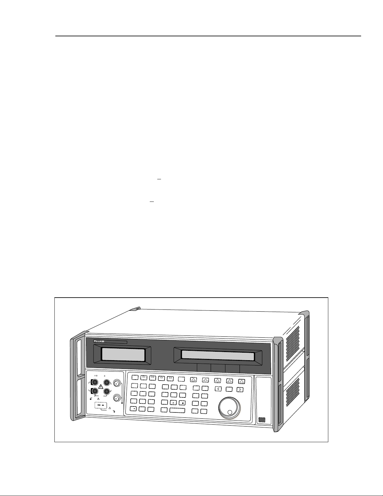
1-1. 5500A Multi-Product Calibrator ............................................................................ 1-3
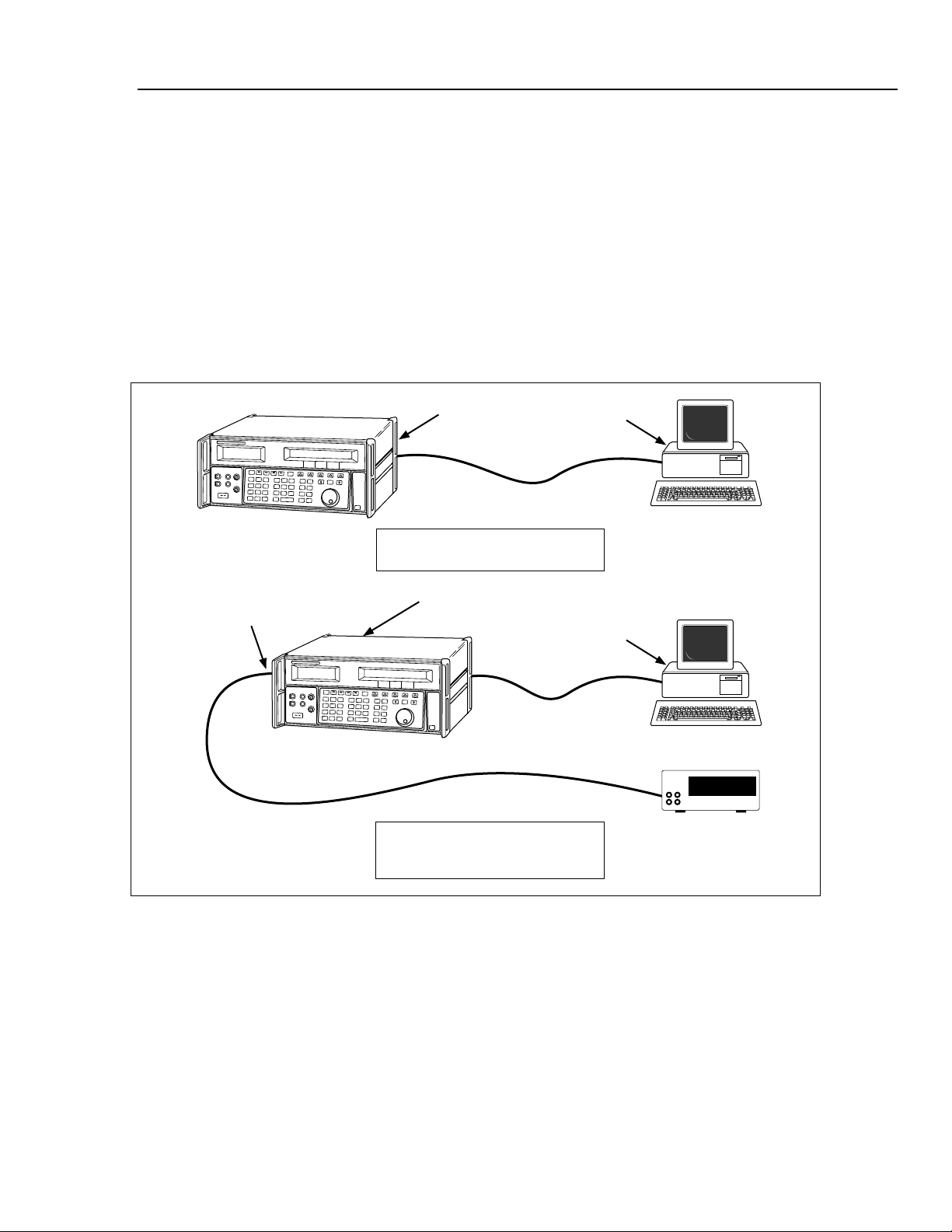
1-2. RS-232 Remote Connections ................................................................................. 1-5
1-3. 5725A Amplifier .................................................................................................... 1-8
2-1. Accessing the Fuse and Selecting Line Voltage .................................................... 2-5
2-2. Line Power Cord Types Available from Fluke ...................................................... 2-6
3-1. Front Panel View.................................................................................................... 3-4
3-2. Rear Panel View..................................................................................................... 3-10
3-3. SETUP Softkey Menu Tree ................................................................................... 3-12
3-4. SETUP Softkey Menu Displays............................................................................. 3-13
3-5. MEAS TC Softkey Menu Tree............................................................................... 3-22
3-6. MEAS TC Softkey Menu Displays........................................................................ 3-23
4-1. UUT Connection: Resistance (Four-Wire Compensation)..................................... 4-12
4-2. UUT Connection: Resistance (Two-Wire Compensation)..................................... 4-12
4-3. UUT Connection: Resistance (Compensation Off)................................................ 4-13
4-4. UUT Connection: Capacitance (Four-Wire Compensation) .................................. 4-13
4-5. UUT Connection: Capacitance (Two-Wire Compensation) .................................. 4-14
4-6. UUT Connection: Capacitance (Compensation Off) ............................................. 4-14
4-7. UUT Connection: DC Voltage/AC Voltage........................................................... 4-15
4-9. UUT Connection: Temperature (RTD) .................................................................. 4-15
4-10. UUT Connection: Temperature (Thermocouple)................................................... 4-16
4-11. Sinewave ................................................................................................................ 4-41
4-12. Trianglewave.......................................................................................................... 4-41
4-13. Squarewave and Duty Cycle .................................................................................. 4-42
4-14. Truncated Sinewave ............................................................................................... 4-42
4-15. Cable Connections for Testing an 80 Series General Functions ............................ 4-53
4-16. Cable Connections for Testing an 80 Series Current Function .............................. 4-55
4-17. Cable Connections for Testing an 80 Series High Amps Function........................ 4-57
4-18. Cable Connections for Testing a 40 Series Watts Function ................................... 4-59
4-19. Cable Connections for Testing a 50 Series Thermometer...................................... 4-62
5-1. Typical IEEE-488 Remote Control Connections ................................................... 5-5
5-2. Typical RS-232 Remote Control Connections....................................................... 5-6
5-3. Typical IEEE-488 Port Connections ...................................................................... 5-8
5-4. Typical PC COM Port Connections ....................................................................... 5-12
xi
Page 20

5500A
Operator Manual
5-5. Typical RS-232 UUT Port via RS-232 Host Port Connections ............................. 5-17
5-6. Typical RS-232 UUT Port via IEEE-488 Port Connections .................................. 5-19
5-7. IEEE-488 Remote Message Coding....................................................................... 5-25
5-8. Status Register Overview ....................................................................................... 5-37
5-9. Status Byte and SRE Bit Definitions...................................................................... 5-38
5-11. Bit Assignments for the ISR, ISCEs and ISCRs .................................................... 5-42
7-1. Accessing the Fuse................................................................................................. 7-4
7-2. Accessing the Air Filter.......................................................................................... 7-5
xii
Page 21

Chapter 1
Introduction and Specifications
Contents Page
1-1.
Introduction........................................................................................... 1-3
How to Contact Fluke........................................................................... 1-4
1-2.
1-3. Operation Overview.............................................................................. 1-4
1-4. Local Operation................................................................................ 1-4
1-5. Remote Operation (RS-232)............................................................. 1-4
1-6. Remote Operation (IEEE-488) ......................................................... 1-5
1-7. Where To Go from Here....................................................................... 1-6
1-8. Instruction Manuals .............................................................................. 1-6
1-9. 5500A Operator Manual................................................................... 1-6
1-10. 5500A Operator Reference Guide .................................................... 1-7
1-11. 5500A Remote Programming Reference Guide............................... 1-7
1-12. 5500A Service Manual ..................................................................... 1-7
1-13. 5725A Amplifier................................................................................... 1-7
1-14. Specifications........................................................................................ 1-9
1-15. General Specifications .......................................................................... 1-10
1-16. DC Voltage Specifications ............................................................... 1-11
1-17. DC Current Specifications................................................................ 1-12
1-18. Resistance Specifications ................................................................. 1-13
1-19. AC Voltage (Sine Wave) Specifications .......................................... 1-14
1-20. AC Current (Sine Wave) Specifications........................................... 1-17
1-21. Capacitance Specifications............................................................... 1-19
1-22. Temperature Calibration (Thermocouple) Specifications ................ 1-20
1-23. Temperature Calibration (RTD) Specifications................................ 1-21
1-24. DC Power Specification Summary................................................... 1-22
1-25. AC Power (45 Hz to 65 Hz) Specification Summary, PF=1 ............ 1-22
1-26. Power and Dual Output Limit Specifications................................... 1-23
1-27. Phase Specifications ......................................................................... 1-24
1-28. Calculating Power Uncertainty......................................................... 1-25
1-29. Additional Specifications...................................................................... 1-26
1-30. Frequency Specifications.................................................................. 1-26
1-31. Harmonics (2nd to 50th) Specifications.............................................. 1-26
1-32. AC Voltage (Sine Wave) Extended Bandwidth Specifications........ 1-27
1-33. AC Voltage (Non-Sine Wave) Specifications .................................. 1-28
1-34. AC Voltage, DC Offset Specifications............................................. 1-29
1-35. AC Voltage, Square Wave Characteristics....................................... 1-29
1-1
Page 22

5500A
Operator Manual
1-36. AC Voltage, Triangle Wave Characteristics (typical)...................... 1-29
1-37. AC Current (Sine Wave) Extended Bandwidth Specifications ........ 1-29
1-38. AC Current (Non-Sinewave) Specifications .................................... 1-30
1-39. AC Current (Non-Sinewave) Specifications (cont).......................... 1-31
1-40. AC Current, Square Wave Characteristics (typical)......................... 1-31
1-41. AC Current, Triangle Wave Characteristics (typical) ...................... 1-31
1-2
Page 23
Introduction and Specifications
Introduction 1
1-1. Introduction
The Fluke Model 5500A Multi-Product Calibrator (Figure 1-1) is a precise instrument
that calibrates a wide variety of electrical measuring instruments. With the 5500A
Calibrator, you can calibrate precision multimeters that measure ac or dc voltage, ac or dc
current, ac or dc power, resistance, capacitance, and temperature. With the Oscilloscope
Calibration option, you can use the 5500A Calibrator to calibrate analog and digital
oscilloscopes. Specifications are provided in this chapter (specifications for the
Oscilloscope Calibration option are provided in Chapter 8).
XW Warning
If the 5500A Calibrator is operated in any way not specified by
this manual or other documentation provided by Fluke, the
protection provided by the Calibrator may be impaired.
The 5500A Calibrator is a fully programmable precision source of the following:
• DC voltage from 0 V to +
1020 V.
• AC voltage from 1 mV to 1020 V, with output from 10 Hz to 500 kHz.
• AC current from 0.01 µA to 11.0 A, with output from 10 Hz to 10 kHz.
• DC current from 0 to +
11.0 A.
• Resistance values from a short circuit to 330 MΩ.
• Capacitance values from 330 pF to 1100 µF.
• Simulated output for three types of Resistance Temperature Detectors (RTDs).
• Simulated output for nine types of thermocouples.
Features of the 5500A Calibrator include the following:
• Automatic meter error calculation.
• X and D keys that change the output value to pre-determined cardinal values
for various functions.
• Programmable entry limits that prevent invalid amounts from being entered.
5500A
CALIBRATOR
NORMAL AUX
V, ,
RTD
1000V
RMS
MAX
20V PK
MAX
TC
HI
LO
1V PK
MAX
A, -SENSE,
AUX V
SCOPE
60V PK
MAX
STBY
OPR
EARTH
SCOPE
20V
RMS
MAX
TRIG
OUT
20V PK
MAX
7
8
9
4
5
6
1
2
3
+
/
0
•
PREV
BOOST
MENU
µ
d
B
mse
c
m
V
n
W
k
A
p
M
SHIFT
ENTER
SETUP
Hz
¡F
¡C
F
RESET
NEW
CE
REF
MEAS
TRIG
TC
OUT
MULT
DIV
x
÷
EDIT
FIELD
POWER
F1-01.eps
Figure 1-1. 5500A Multi-Product Calibrator
1-3
Page 24

5500A
Operator Manual
1-2. How to Contact Fluke
• Simultaneous output of voltage and current, up to 11 kW.
• Simultaneous output of two voltages.
• Extended bandwidth mode outputs multiple waveforms down to 0.01 Hz, and sine
waves to 2 MHz.
• Variable phase signal output.
• Standard IEEE-488 (GPIB) interface, complying with ANSI/IEEE Standards
488.1-1987 and 488.2-1987.
• EIA Standard RS-232-C serial data interface for printing, displaying, or transferring
internally stored calibration constants, and for remote control of the 5500A.
• Pass-through RS-232-C serial data interface for communicating with the Unit Under
Test (UUT).
• Extensive automatic internal self testing and diagnostics of analog and digital
functions.
To contact Fluke, call one of the following telephone numbers:
USA: 1-888-99-FLUKE (1-888-993-5853)
Canada: 1-800-36-FLUKE (1-800-363-5853)
Europe: +31 402-675-200
Japan: +81-3-3434-0181
Singapore: +65-738-5655
Anywhere in the world: +1-425-446-5500
Or, visit Fluke's Web site at www.fluke.com
To register your product, visit register.fluke.com
.
.
1-3. Operation Overview
The 5500A Calibrator may be operated at the front panel in the local mode, or remotely
using RS-232 or IEEE-488 ports. For remote operations, several software options are
available to integrate 5500A operation into a wide variety of calibration requirements.
1-4. Local Operation
Typical local operations include front panel connections to the Unit Under Test (UUT),
and then manual keystroke entries at the front panel to place the calibrator in the desired
output mode. The front panel layout facilitates hand movements from left to right, and
multiply and divide keys make it easy to step up or down at the press of a single key. You
can also review 5500A Calibrator specifications at the push of a button [available, July,
1995]. The backlit liquid crystal display is easy to read from many different viewing
angles and lighting conditions, and the large, easy-to-read keys are color-coded and
provide tactile feedback when they are pressed.
1-4
1-5. Remote Operation (RS-232)
There are two rear-panel serial data RS-232 ports: SERIAL 1 FROM HOST, and
SERIAL 2 TO UUT (Figure 1-2). Each port is dedicated to serial data communications
for operating and controlling the 5500A during calibration procedures. For complete
information on remote operations, see Chapter 5.
Page 25
Introduction and Specifications
Operation Overview 1
The SERIAL 1 FROM HOST serial data port connects a host terminal or personal
computer to the 5500A. You have several choices for sending commands to the 5500A:
you can enter commands from a terminal (for example, using the Terminal accessory
from Windows using a PC), you can write your own programs using BASIC, or you can
run optional Windows-based software such as 5500/CAL or MET/CAL. The 5500/CAL
software includes more than 200 example procedures covering a wide range of test tools
the 5500A can calibrate. (See Chapter 6 for a discussion of the RS-232 commands.)
The SERIAL 2 TO UUT serial data port connects a UUT to a PC or terminal via the
5500A (see Figure 1-2). This “pass-through” configuration eliminates the requirement for
two COM ports at the PC or Terminal. A set of four commands control the operation of
the SERIAL 2 TO UUT serial port. See Chapter 6 for a discussion of the UUT_*
commands.
5500A
SERIAL 2
TO UUT port
SERIAL 1 FROM HOST port
RS-232 Remote Operation using the
SERIAL 1 FROM HOST port
SERIAL 1 FROM HOST port
5500A
RS-232 Remote Operation using the
SERIAL 1 FROM HOST and
SERIAL 2 TO UUT ports
Figure 1-2. RS-232 Remote Connections
COM port
COM port
PC or Terminal
PC or Terminal
Unit Under Test
F1-02.eps
1-6. Remote Operation (IEEE-488)
The 5500A rear panel IEEE-488 port is a fully programmable parallel interface bus
meeting standard IEEE-488.1 and supplemental standard IEEE-488.2. Under the remote
control of an instrument controller, the 5500A Calibrator operates exclusively as a
“talker/listener.” You can write your own programs using the IEEE-488 command set or
run the optional Windows-based MET/CAL software. (See Chapter 6 for a discussion of
the commands available for IEEE-488 operation.)
1-5
Page 26

5500A
Operator Manual
1-7. Where To Go from Here
To locate specific information concerning the installation and operation of the 5500A
calibrator, refer to the following list:
• Unpacking and setup: Chapter 2, “Preparing for Operation”
• Installation and rack mounting: Chapter 2, “Preparing for Operation,” and the rack
mount kit instruction sheet
• AC line power and interface cabling: Chapter 2, “Preparing for Operation”
• Controls, indicators, and displays: Chapter 3, “Features”
• Front panel operation: Chapter 4, “Front Panel Operation”
• Cabling to a UUT (Unit Under Test): Chapter 4, “Front Panel Operation”
• Using the auxiliary amplifier: Chapter 4, “Front Panel Operation”
• Remote operation (IEEE-488 or serial): Chapter 5, “Remote Operation”
• Calibrating an Oscilloscope: Chapter 8, “Oscilloscope Calibration Option”
• Accessories to the 5500A Calibrator: Chapter 9, “Accessories”
• Instrument specifications: Chapter 1, “Introduction and Specifications”
1-8. Instruction Manuals
The 5500A Manual Set provides complete information for opearators and service or
maintenance technicians. The set includes:
• 5500A Getting Started Manual (PN 945159)
• 5500A Operator Reference Guide (PN 945097)
• 5500A Remote Programming Reference Guide (PN 105783)
• 5500A Operator Manual (Provided on CD-ROM or printed copy available for
purchase (PN 1628802) through the Fluke Service Department.)
• 5500A Service Manual (PN 105798)
The two reference guides and the Getting Started manual are shipped with the unit. Order
additional copies of the manuals or reference guides separately using the part number
provided. For ordering instructions, refer to the Fluke Catalog, or ask a Fluke sales
representative (see “Service Information” in Chapter 2). The Operator and Service
Manuals are both provided on the CD-ROM.
1-9. 5500A Operator Manual
This 5500A Operator Manual provides complete information for installing the 5500A
Calibrator and operating it from the front panel keys and in remote configurations. This
manual also provides a glossary of calibration, specifications, and error code information.
The Operator Manual includes the following topics:
1-6
• Installation
• Operating controls and features, including front panel operation
• Remote operation (IEEE-488 bus or serial port remote control)
• Serial port operation (printing, displaying, or transferring data, and setting up for
serial port remote control)
Page 27

Introduction and Specifications
• Operator maintenance, including verification procedures and calibration approach for
the 5500A
• Oscilloscope Calibration Option
• Accessories
1-10. 5500A Operator Reference Guide
The 5500A Operator Reference Guide contains a summary of operating instructions, and
a front panel and rear panel feature reference.
1-11. 5500A Remote Programming Reference Guide
The 5500A Remote Programming Reference Guide contains a summary of remote
commands and reference information useful in determining system status using the status
byte and related registers.
1-12. 5500A Service Manual
The 5500A Service Manual can be ordered through your local Fluke Sales or Service
representative (see “Service Information” in Chapter 2). The 5500A Service Manual
includes: theory of operation, performance testing, maintenance, calibration,
troubleshooting, parts lists, and schematic diagrams.
5725A Amplifier 1
1-13. 5725A Amplifier
The Fluke 5725A Amplifier (Figure 1-3) is an external unit operating under 5500A
control to extend the Volts x Hertz and voltage compliance of the calibrator. The
amplifier adds the following capabilities with no compromise in accuracy:
Frequency Increase to 100 kHz at 750 V, 30 kHz at 1020 V.
AC Voltage Load limit extended to 70 mA for frequencies above 5 kHz, and to 50 mA
for frequencies less than 5 kHz. Capacitive drive increases to 1020 pF, subject to the
maximum output current, for volts ac.
AC Current 11 A load limit extended to 10 kHz, with a 3-volt drive compliance.
A separate set of binding posts on the front panel of the 5725A supplies extended
capability. Since most meters have a separate input terminal for the high current ranges,
this eliminates the need to change cables during a procedure.
1-7
Page 28
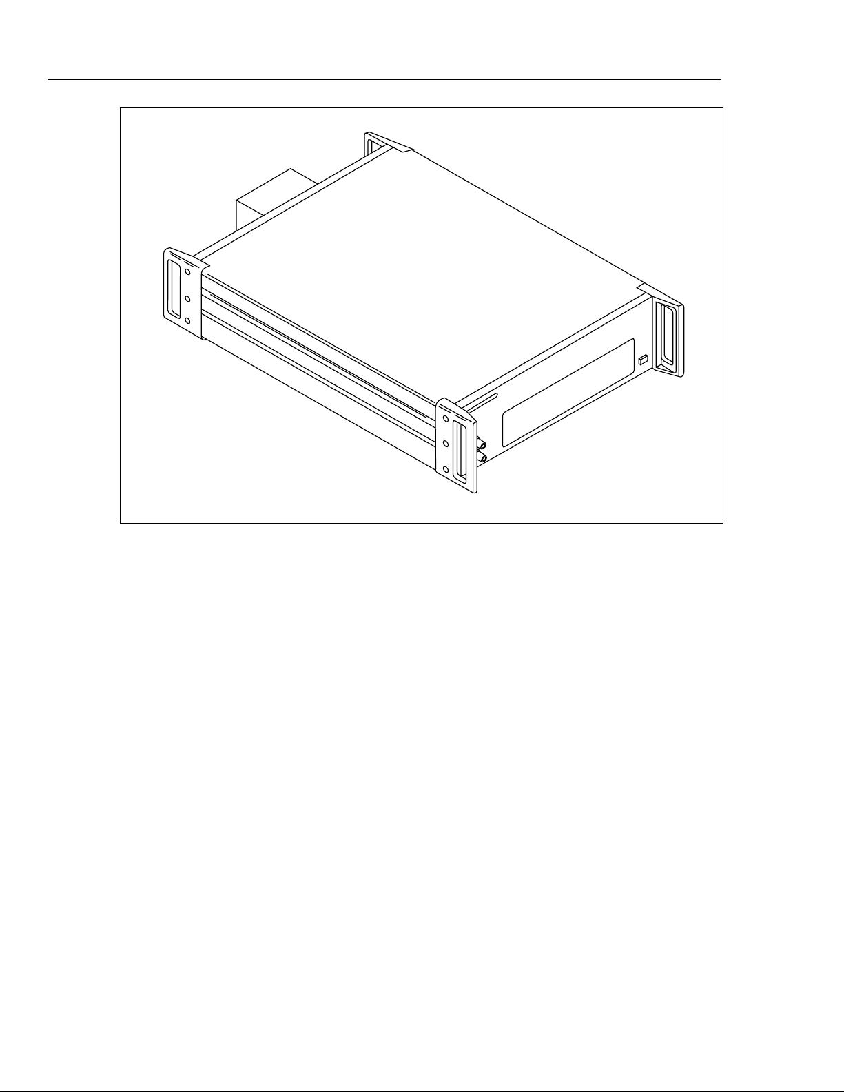
5500A
Operator Manual
Figure 1-3. 5725A Amplifier
F1-03.eps
1-8
Page 29
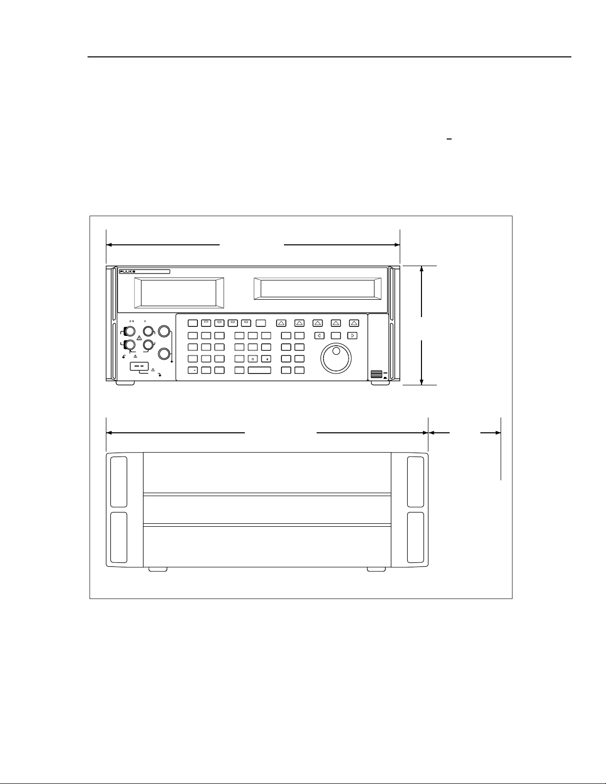
Introduction and Specifications
Specifications 1
1-14. Specifications
The following paragraphs detail specifications for the 5500A Calibrator. The specifications are valid after allowing a
warm-up period of 30 minutes, or twice the time the 5500A has been turned off. For example, if the 5500A has been
turned off for 5 minutes, the warm-up period is 10 minutes.
All specifications apply for the temperature and time period indicated. For temperatures outside of tcal +
ambient temperature when the 5500A was calibrated), the temperature coefficient is less than 0.1 times the 90-day
specifications per °C (limited to 0 °C to 50 °C). These specifications also assume the 5500A Calibrator is zeroed every
seven days or when the ambient temperature changes more than 5 °C. (See “Zeroing the Calibrator” in Chapter 4 of the
5500A Operator Manual.)
Also see additional specifications later in this chapter for information on extended specifications for ac voltage and
current. The dimensional outline for the 5500A Calibrator is shown in Figure A.
43.2 cm (17 in)
CALIBRATOR
5500A
5 °C (tcal is the
NORMAL AUX
V, ,
RTD
1000V
RMS
MAX
20V PK
MAX
TC
1V PK
MAX
A, -SENSE,
HI
LO
SCOPE
200V PK
MAX
AUX V
20V
RMS
MAX
20V PK
MAX
STBY
OPR EARTH SCOPE BOOST MENU
TRIG
OUT
789
456
123
+
0
/
µ
m
npW
k
M
SHIFT
PREV
dBm sec
VHz
¡F
¡CA
F
ENTER
SETUP
NEW
REF
MEAS
TC
MULTxDIV
RESET
EDIT
FIELD
CE
TRIG
OUT
POWER
(7 in)
I
O
17.8 cm
47.0 cm (18.5 in) 6.4 cm
(2.5 in)
For Cable
Access
om002f.ewps
Figure A. 5500A Calibrator Dimensional Outline
1-9
Page 30

5500A
Operator Manual
1-15. General Specifications
Warmup Time
Settling Time
Standard Interfaces
Temperature Performance
Temperature Coefficient
Relative Humidity
Altitude
Safety
Analog Low Isolation
EMC
Line Power
Power Consumption
Dimensions
Weight (without options)
Absolute Uncertainty Definition
Specification Confidence
Interval
[1] After long periods of storage at high humidity, a drying out period (with the power on) of at least one week may be required.
Twice the time since last warmed up, to a maximum of 30 minutes.
Less than 5 seconds for all functions and ranges except as noted.
IEEE-488 (GPIB), RS-232, 5725ª Amplifier
• Operating: 0 °C to 50 °C
• Calibration (tcal): 15 °C to 35 °C
• Storage: -20 °C to 70 °C
Temperature Coefficient for temperatures outside tcal +5 °C is 0.1X/ °C of the
[1]
90-day specification (or 1-year, as applicable) per °C.
• Operating: <80 % to 30 °C, <70 % to 40 °C, <40 % to 50 °C
• Storage: <95 %, non-condensing
• Operating: 3,050 m (10,000 ft) maximum
• Non-operating: 12,200 m (40,000 ft) maximum
Complies with IEC 1010-1 (1992-1); ANSI/ISA-S82.01-1994;
CAN/CSA-C22.2 No. 1010.1-92
20 V
Designed to comply with FCC Rules Part 15; VFG 243/1991. If used in areas with
Electromagnetic fields of 1 to 3 V/m, resistance outputs have a floor adder of
0.508 Ω. Performance not specified above 3 V/m. This instrument may be
susceptible to electro-static discharge (ESD) from direct contact to the binding posts.
Good static aware practices should be followed when handling this and other pieces
of electronic equipment.
• Line Voltage (selectable): 100 V, 120 V, 220 V, 240 V
• Line Frequency: 47 Hz to 63 Hz
• Line Voltage Variation: ±10 % about line voltage setting
5500A Calibrator, 300 VA; 5725A Amplifier, 750 VA
5500A Calibrator:
• Height: 17.8 cm (7 in), standard rack increment, plus 1.5 cm (0.6 in) for feet on
bottom of unit
• Width, 43.2 cm (17 in), standard rack width
• Depth: 47.3 cm (18.6 in) overall
5725A Amplifier:
• Height, 13.3 cm (5.25 in), standard rack increment, plus 1.5 cm (0.6 in) for feet on
bottom of unit
• Width, 43.2 cm (17 in), standard rack width
• Depth, 63.0 cm (24.8 in) overall.
5500A Calibrator, 22 kg (49 lb); 5725A Amplifier 32 kg (70 lb)
The 5500A specifications include stability, temperature coefficient, linearity, line and
load regulation, and the traceability of the external standards used for calibration.
You do not need to add anything to determine the total specification of the 5500A for
the temperature range indicated.
99 %
1-10
Page 31

Introduction and Specifications
General Specifications 1
1-16. DC Voltage Specifications
Absolute Uncertainty, tcal ± 5 °C
Range
0 to 329.9999 mV 0.005 3 0.006 3 5 + 1 0.1
0 to 3.299999 V 0.004 5 0.005 5 4 + 3 1 10 mA
0 to 32.99999 V 0.004 50 0.005 50 4 + 30 10 10 mA
30 to 329.9999 V 0.0045 500 0.0055 500 4.5 + 300 100 5 mA
100 to 1020.000 V 0.0045 1500 0.0055 1500 4.5 + 900 1000 5 mA
0 to 329.999 mV 0.03 350 0.04 350 30 + 100 1 5 mA
0.33 to 3.3 V 0.03 350 0.04 350 30 + 100 10 5 mA
[1] Remote sensing is not provided. Output resistance is < 5 mΩ for outputs ≥ 0.33 V. The AUX output has an output resistance
of < 1 Ω.
[2] Two channels of dc voltage output are provided.
± (% of output + µV)
90 days 1 year
Auxiliary Output (dual output mode only)
Stability
24 hours, ± 1 °C
± (ppm output + µV)
[2]
Resolution
µV
Maximum
Burden
[1]
50 Ω
Noise
Range
0 to 329.9999 mV
0 to 3.299999 V
0 to 32.99999 V
30 to 329.9999 V 10 ppm + 1 mV 20 mV
100 to 1020.000 V 10 ppm + 5 mV 20 mV
0 to 329.999 mV
0.33 to 3.3 V
[1] Two channels of dc voltage output are provided.
Bandwidth 0.1 to 10 Hz p-p
± (ppm output + µV)
1 µV 4 µV
10 µV 50 µV
100 µV 600 µV
Auxiliary Output (dual output mode only)
5 µV 20 µV
20 µV 200 µV
Bandwidth 10 to 10 kHz rms
[1]
1-11
Page 32

5500A
Operator Manual
1-17. DC Current Specifications
0 to 3.29999 mA 0.010 0.05 0.013 0.05
0 to 32.9999 mA 0.008 0.25 0.01 0.25
0 to 329.999 mA 0.008 3.3 0.01 3.3
0 to 2.19999 A 0.023 44 0.03 44
[1] The actual voltage compliance (Vc) is a function of current output (Io), and is given by the formula:
[2] The actual voltage compliance (Vc) is a function of current output (Io), and is given by the formula:
[3] The actual voltage compliance (Vc) is a function of current output (Io), and is given by the formula:
0 to 3.29999 mA 20 nA 200 nA
0 to 32.9999 mA 200 nA
0 to 329.999 mA 2000 nA
0 to 2.19999 A
Absolute Uncertainty,
Range
tcal ± 5 °C
± (% of output + µA)
Resolution
Compliance
Voltage
90 days 1 year
4.5 V
4.5 V
4.5 to 3.0 V
4.5 to 3.4 V
4.3 to 2.5 V
0 to 11 A 0.038 330 0.06 330
0.01 µA
0.1 µA
1 µA
10 µA
100 µA
5725A Amplifier
0 to 11 A 0.03 330 0.04 330 100 4 V
Vc = -5.05*Io+4.67. The highest compliance voltage is limited to 4.5 V.
Vc = -0.588*Io+4.69. The highest compliance voltage is limited to 4.5 V.
Vc = -0.204*Io+4.75. The highest compliance voltage is limited to 4.3 V.
Noise
Ranges
Bandwidth
0.1 to 10 Hz
p-p
20 µA
0 to 11 A
200 µA
5725A Amplifier
0 to 11 A ± 25 ppm of output + 200 nA 2 mA
Bandwidth
10 to 10 kHz
rms
2.0 µA
20 µA
1 mA
10 mA
[2]
[1]
[3]
Maximum
Inductive
Load
1 µH
200 µH
200 µH
200 µH
200 µH
400 µH
1-12
Page 33

Introduction and Specifications
General Specifications 1
1-18. Resistance Specifications
Absolute Uncertainty, tcal ± 5 °C
± (% of output + Ω)
Range
[1]
90 days 1 year
0 to 10.99 Ω
11 to 32.999 Ω
33 to 109.999 Ω
110 to 329.999 Ω
330 Ω to 1.09999 kΩ
1.1 to 3.29999 kΩ
3.3 to 10.9999 kΩ
11 to 32.9999 kΩ
33 to 109.999 kΩ
110 to 329.999 kΩ
330 kΩ to 1.09999 MΩ
1.1 to 3.29999 MΩ
3.3 to 10.9999 MΩ
11 to 32.9999 MΩ
33 to 109.999 MΩ
110 to 330 MΩ
[1] Continuously variable from 0 to 330 MΩ.
[2] Applies for COMP OFF (to the 5500A Calibrator front panel NORMAL terminals) and 2-wire and 4-wire compensation.
[3] The floor adder is improved to 0.006 Ω (0 to 10.99 Ω range) and 0.010 Ω (11 to 329.999 Ω) if the 5500A Calibrator is zeroed
(ohms zero or instrument zero) within 8 hours and temperature is ±1 °C of zeroing ambient temperature.
[4] Do not exceed the largest current for each range. For currents lower than shown, the floor adder increases by
Floor(new) = Floor(old) x Imin/Iactual. For example, a 100 µA stimulus measuring 100 Ω has a floor uncertainty of 0.01 Ω x 1
mA/100 µA = 0.1 Ω.
0.009 0.008
0.009 0.015
0.007 0.015
0.007 0.015
0.007 0.06 0.009 0.06 0.01
0.007 0.06 0.009 0.06 0.01
0.007 0.6 0.009 0.6 0.1
0.007 0.6 0.009 0.6 0.1
0.008 6 0.011 6 1
0.009 6 0.012 6 1
0.011 55 0.015 55 10 250 nA to 0.018 mA
0.011 55 0.015 55 10
0.045 550 0.06 550 100
0.075 550 0.1 550 100
0.4 5500 0.5 5500 1000
0.4 16500 0.5 16500 1000
[3]
0.012 0.008
[3]
0.012 0.015
[3]
0.009 0.015
[3]
0.009 0.015
[2]
Resolution
Ω
[3]
0.001 1 to 125 mA
[3]
0.001 1 to 125 mA
[3]
0.001 1 to 70 mA
[3]
0.001 1 to 40 mA
Allowable
Current
[4]
250 µA to 18 mA
250 µA to 5 mA
25 µA to 1.8 mA
25 µA to 0.5 mA
2.5 µA to 0.18 mA
2.5 µA to 0.05 mA
250 nA to 5 µA
25 nA to 1.8 µA
25 nA to 0.5 µA
2.5 nA to 0.18 µA
2.5 nA to 0.06 µA
Range
0 to 10.99 Ω
11 to 32.999 Ω
33 to 109.999 Ω
110 to 329.999 Ω
330 Ω to 1.09999 kΩ
1.1 to 3.29999 kΩ
3.3 to 10.9999 kΩ
11 to 32.9999 kΩ
33 to 109.999 kΩ
110 to 329.999 kΩ
330 kΩ to 1.09999 MΩ
1.1 to 3.29999 MΩ
3.3 to 10.9999 MΩ
11 to 32.9999 MΩ
33 to 109.999 MΩ
110 to 330 MΩ
[1] This is for the largest resistance for each range. The maximum voltage for other values is Imax (highest value of Allowable Current
above) multiplied by Rout.
[2] Maximum lead resistance for no additional error in 2-wire COMP.
Maximum Voltage
1.37 V
4.12 V
7.7 V
13.2 V
19.8 V
16.5 V
19.8 V
16.5 V
19.8 V
16.5 V
19.8 V
16.5 V
19.8 V
16.5 V
19.8 V
19.8 V
[1]
Maximum Lead Resistance
<3.2 Ω
<3.2 Ω
<3.2 Ω
<3.2 Ω
<6 Ω
<6 Ω
<6 Ω
<6 Ω
<6 Ω
(n/a 110 kΩ and above)
[2]
1-13
Page 34

5500A
Operator Manual
1-19. AC Voltage (Sine Wave) Specifications
1.0 to 32.999 mV
33 to 329.999 mV
0.33 to 3.29999 V
3.3 to 32.9999 V
33 to 329.999 V
330 to 1020 V
Range
Absolute Uncertainty, tcal ± 5 °C
Frequency
10 to 45 Hz 0.26 20 0.35 20
45 Hz to 10 kHz 0.11 20 0.15 20
10 to 20 kHz 0.15 20 0.2 20
20 to 50 kHz 0.19 20 0.25 20
50 to 100 kHz 0.26 33 0.35 33
100 to 500 kHz 0.75 60 1 60
10 to 45 Hz 0.19 50 0.25 50
45 Hz to 10 kHz 0.04 20 0.05 20
10 to 20 kHz 0.08 20 0.1 20
20 to 50 kHz 0.12 40 0.16 40
50 to 100 kHz 0.17 170 0.24 170
100 to 500 kHz 0.53 330 0.7 330
10 to 45 Hz 0.11 250 0.15 250
45 Hz to 10 kHz 0.02 60 0.03 60
10 to 20 kHz 0.06 60 0.08 60
20 to 50 kHz 0.10 300 0.14 300
50 to 100 kHz 0.17 1700 0.24 1700
100 to 500 kHz 0.38 3300 0.5 3300
10 to 45 Hz 0.11 2500 0.15 2500
45 Hz to 10 kHz 0.03 600 0.04 600
10 to 20 kHz 0.06 2600 0.08 2600
20 to 50 kHz 0.14 5000 0.19 5000
50 to 100 kHz 0.17 17000 0.24 17000
45 Hz to 1 kHz 0.04 6.6 mV 0.05 6.6 mV
1 to 10 kHz 0.06 15 0.08 15
10 to 20 kHz 0.07 33 0.09 33
45 Hz to 1 kHz 0.04 80 mV 0.05 80 mV
1 to 5 kHz 0.15 100 0.20 100
5 to 10 kHz 0.15 500 0.20 500
± (% of output + µV)
90 days 1 year
Resolution
1 µV 50 Ω
1 µV 50 Ω
10 µV
100 µV
5 mA, except
1 mV
2 mA, except
10 mV
Max
[1]
Burden
10 mA
10 mA
20 mA for
45 to 65 Hz
6 mA for
45 to 65 Hz
1-14
Page 35

Introduction and Specifications
General Specifications 1
AC Voltage (Sine Wave) Specifications (cont.)
Absolute Uncertainty, tcal ± 5 °C
Range Frequency
45 Hz to 1 kHz 0.04 80 mV 0.05 80 mV 50 mA
100 to 1020 V
100 to 750 V 30 to 100 kHz 0.38 500 mV 0.5 500 mV
10 to 329.999 mV
0.33 to 3.29999 V
[1] Remote sensing is not provided. Output resistance is < 5 mΩ for outputs ≥ 0.33 V. The AUX output resistance is < 1 Ω. The
maximum load capacitance is 500 pF, subject to the maximum burden current limits.
[2] There are two channels of voltage output. The maximum frequency of the dual output is 10 kHz.
1 to 20 kHz 0.06 100 mV 0.08 100 mV 70 mA
20 to 30 kHz 0.08 100 mV 0.10 100 mV 70 mA
Auxiliary Output [dual output mode only]
10 to 20 Hz 0.15 370 0.2 370
20 to 45 Hz 0.08 370 0.1 370
45 Hz to 1 kHz 0.08 370 0.1 370
1 to 5 kHz 0.15 450 0.2 450
5 to 10 kHz 0.3 450 0.4 450
10 to 20 Hz 0.15 450 0.2 450
20 to 45 Hz 0.08 450 0.1 450
45 Hz to 1 kHz 0.07 450 0.09 450
1 to 5 kHz 0.15 1400 0.2 1400
5 to 10 kHz 0.3 1400 0.4 1400
± (% of output + µV)
90 days 1 year
5725A Amplifier
Resolution
10 mV
[2]
1 µV
10 µV
Maximum
Burden
70 mA
5 mA
5 mA
[1]
1-15
Page 36

5500A
Operator Manual
AC Voltage (Sine Wave) Specifications (cont.)
1.0 to 32.999 mV
33 to 329.999 mV
0.33 to 3.29999 V
3.3 to 32.9999 V
10 to 329.999 mV
0.33 to 3.29999 V
Maximum Distortion and Noise
Range Frequency
10 to 45 Hz 0.15 + 90
45 Hz to 10 kHz 0.035 + 90
10 to 20 kHz 0.06 + 90
20 to 50 kHz 0.15 + 90
50 to 100 kHz 0.25 + 90
100 to 500 kHz 0.3 + 90
10 to 45 Hz 0.15 + 90
45 Hz to 10 kHz 0.035 + 90
10 to 20 kHz 0.06 + 90
20 to 50 kHz 0.15 + 90
50 to 100 kHz 0.20 + 90
100 to 500 kHz 0.20 + 90
10 to 45 Hz 0.15 + 200
45 Hz to 10 kHz 0.035 + 200
10 to 20 kHz 0.06 + 200
20 to 50 kHz 0.15 + 200
50 to 100 kHz 0.20 + 200
100 to 500 kHz 0.20 + 200
10 to 45 Hz 0.15 + 2 mV
45 Hz to 10 kHz 0.035 + 2 mV
10 to 20 kHz 0.08 + 2 mV
20 to 50 kHz 0.2 + 2 mV
50 to 100 kHz 0.5 + 2 mV
45 Hz to 1 kHz 0.15 + 10 mV
33 to 329.999 V
330 to 1000 V
100 to 1020 V
100 to 750 V 30 to 100 kHz 0.4 %
Auxiliary Output (dual output mode only) 10 Hz to 100 kHz Bandwidth
1 to 10 kHz 0.05 + 10 mV
10 to 20 kHz 0.6 + 10 mV
45 Hz to 1 kHz 0.15 + 30 mV
1 to 10 kHz 0.07 + 30 mV
5725A Amplifier
45 Hz to 1 kHz 0.07 %
1 to 20 kHz 0.15 %
20 to 30 kHz 0.3 %
10 to 20 Hz 0.2 + 200
20 to 45 Hz 0.06 + 200
45 Hz to 1 kHz 0.08 + 200
1 to 5 kHz 0.3 + 200
5 to 10 kHz 0.6 + 200
10 to 20 Hz 0.2 + 200
20 to 45 Hz 0.06 + 200
45 Hz to 1 kHz 0.08 + 200
1 to 5 kHz 0.3 + 200
5 to 10 kHz 0.6 + 200
10 Hz to 5 MHz Bandwidth
± (% output + µV)
1-16
Page 37

Introduction and Specifications
General Specifications 1
1-20. AC Current (Sine Wave) Specifications
Rang e Frequency
10 to 20 Hz 0.19 0.15 0.25 0.15
20 to 45 Hz 0.09 0.15 0.125 0.15
0.029 to 0.32999 mA
0.33 to 3.2999 mA
3.3 to 32.999 mA
33 to 329.99 mA
0.33 to 2.19999 A
2.2 to 11 A
45 Hz to 1 kHz 0.09 0.25 0.125 0.25
1 to 5 kHz 0.30 0.15 0.4 0.15
5 to 10 kHz 0.94 0.15 1.25 0.15
10 to 20 Hz 0.15 0.3 0.2 0.3
20 to 45 Hz 0.08 0.3 0.1 0.3
45 Hz to 1 kHz 0.08 0.3 0.1 0.3
1 to 5 kHz 0.15 0.3 0.2 0.3
5 to 10 kHz 0.45 0.3 0.6 0.3
10 to 20 Hz 0.15 3 0.2 3
20 to 45 Hz 0.08 3 0.1 3
45 Hz to 1 kHz 0.07 3 0.09 3
1 to 5 kHz 0.15 3 0.2 3
5 to 10 kHz 0.45 3 0.6 3
10 to 20 Hz 0.15 30 0.2 30
20 to 45 Hz 0.08 30 0.1 30
45 Hz to 1 kHz 0.07 30 0.09 30
1 to 5 kHz 0.15 30 0.2 30
5 to 10 kHz 0.45 30 0.6 30
10 to 45 Hz 0.15 300 0.2 300
45 Hz to 1 kHz 0.08 300 0.1 300
1 to 5 kHz 0.7 300 0.75 300
45 to 65 Hz 0.05 2000 0.06 2000
65 to 500 Hz 0.08 2000 0.10 2000
500 Hz to 1 kHz 0.25 2000 0.33 2000
Absolute Uncertainty, tcal ± 5 °C
± (% of output + µA)
90 days 1 year
Resolution
0.01 µA
0.01 µA
0.1 µA
1 µA
10 µA
100 µA
Compliance
Voltage
3.0 V rms
3.0 V rms
3.0 V rms
3.0 to
2.0 V rms
3.0 to
2.0 V rms
2.8 to
1.25 V rms
[1]
[2]
45 to 65 Hz
[3]
Max
Inductive
Load
1 µH
1 µH
200 µH,
10 to
500 Hz
1 µH,
500 Hz to
10 kHz
200 µH,
10 to
500 Hz
5 µH,
500 Hz to
10 kHz
200 µH,
45 to
500 Hz
5 µH,
500 Hz to
5 kHz
200 µH,
1 µH,
65 Hz to
1 kHz
1-17
Page 38

5500A
Operator Manual
AC Current (Sine Wave) Specifications (cont.)
[1] The actual voltage compliance (Vc) is a function of current output (Io), and is given by the formula:
[2] The actual voltage compliance (Vc) is a function of current output (Io), and is given by the formula:
[3] The actual voltage compliance (Vc) is a function of current output (Io), and is given by the formula:
Absolute Uncertainty, tcal ± 5 °C
Rang e Frequency
45 Hz to 1 kHz 0.08 100 0.1 100
1.5 to 11 A
1 to 5 kHz 0.19 5000 0.25 5000
5 to 10 kHz 0.75 10000 1 10000
Vc = -3.37*Io+3.11. The highest compliance voltage is limited to 3.0 V.
Vc = -0.535*Io+3.18. The highest compliance voltage is limited to 3.0 V.
Vc = -0.176*Io+3.19. The highest compliance voltage is limited to 2.8 V.
Range
0.02 to 0.32999 mA
0.33 to 3.2999 mA
3.3 to 32.999 mA
33 to 329.99 mA
0.33 to 2.19999 A
2.2 to 11 A
1.5 to 11 A
± (% of output + µA)
90 days 1 year
5725A Amplifier
Frequency
10 to 20 Hz 0.15 1.0
20 to 45 Hz 0.1 1.0
45 Hz to 1 kHz 0.05 1.0
1 to 5 kHz 0.5 1.0
5 to 10 kHz 1.0 1.0
10 to 20 Hz 0.15 1.5
20 to 45 Hz 0.06 1.5
45 Hz to 1 kHz 0.02 1.5
1 to 5 kHz 0.5 1.5
5 to 10 kHz 1.2 1.5
10 to 20 Hz 0.15 5
20 to 45 Hz 0.05 5
45 Hz to 1 kHz 0.07 5
1 to 5 kHz 0.3 5
5 to 10 kHz 0.7 5
10 to 20 Hz 0.15 50
20 to 45 Hz 0.05 50
45 Hz to 1 kHz 0.07 50
1 to 5 kHz 0.2 50
5 to 10 kHz 0.4 50
10 to 45 Hz 0.2 500
45 Hz to 1 kHz 0.1 500
1 to 5 kHz 1.4 500
45 to 65 Hz 0.2 3 mA
65 to 500 Hz 0.1 3 mA
500 Hz to 1 kHz 0.4 3 mA
5725A Amplifier
45 Hz to 1 kHz 0.05 1 mA
1 to 5 kHz 0.12 1 mA
5 to 10 kHz 0.5 1 mA
Resolution
Compliance
Voltage
Inductive
100 3
Maximum Distortion and Noise
10 Hz to 100 kHz Bandwidth
± (% output + µA)
Max
Load
400 µH
1-18
Page 39

Introduction and Specifications
General Specifications 1
1-21. Capacitance Specifications
Absolute Uncertainty, tcal ± 5 °C
Range
0.33 to 0.4999 nF 0.38 0.01 0.5 0.01 0.1 pF 50 to 1000 Hz 10 kHz
0.5 to 1.0999 nF 0.38 0.01 0.5 0.01 0.1 pF 50 to 1000 Hz 10 kHz
1.1 to 3.2999 nF 0.38 0.01 0.5 0.01 0.1 pF 50 to 1000 Hz 10 kHz
3.3 to 10.999 nF 0.38 0.01 0.5 0.01 1 pF 50 to 1000 Hz 10 kHz
11 to 32.999 nF 0.19 0.1 0.25 0.1 1 pF 50 to 1000 Hz 10 kHz
33 to 109.99 nF 0.19 0.1 0.25 0.1 10 pF 50 to 1000 Hz 10 kHz
110 to 329.99 nF 0.19 0.3 0.25 0.3 10 pF 50 to 1000 Hz 10 kHz
0.33 to 1.0999 µF
1.1 to 3.2999 µF
3.3 to 10.999 µF
11 to 32.999 µF
33 to 109.99 µF
110 to 329.99 µF
330 to 1.1 mF 1 300 1 300 100 nF 50 to 100 Hz 150 Hz
Specifications apply to both dc charge/discharge capacitance meters and ac RCL meters.
The output is continuously variable from 330 pF to 1.1 mF.
For all ranges, the maximum charge and discharge current is 150 mA pk or 30 mA rms. The peak voltage is 4 V, except the 330 µF to
1.1 mF range is limited to 1 V. The maximum lead resistance for no additional error in 2-wire COMP mode is 10 Ω.
± (% of output + nF)
90 days 1 year
0.19 1 0.25 1 100 pF 50 to 1000 Hz 5 kHz
0.26 3 0.35 3 100 pF 50 to 1000 Hz 2 kHz
0.26 10 0.35 10 1 nF 50 to 400 Hz 1.5 kHz
0.30 30 0.40 30 1 nF 50 to 400 Hz 800 Hz
0.38 100 0.50 100 10 nF 50 to 200 Hz 400 Hz
0.50 300 0.70 300 10 nF 50 to 100 Hz 200 Hz
Resolution
Allowed
Frequency
Typical for <1 %
Error
1-19
Page 40

5500A
Operator Manual
1-22. Temperature Calibration (Thermocouple) Specifications
Type
The 10 µV/ °C linear output mode has the same uncertainty as the 300 mV dc range.
Applies to both simulated thermocouple output and thermocouple measurement.
[1]
[2] Resolution is 0.01 °C.
[3] Does not include thermocouple error.
Absolute Uncertainty
TC
[1]
Range (°C)
[2]
Source/Measure,
tcal ± 5 °C
[3]
± (°C)
90 days 1 year
600 to 800 0.42 0.44 -200 to -100 0.37 0.37
B
800 to 1000 0.34 0.34 -100 to 800 0.26 0.26
1000 to 1550 0.30 0.30
1550 to 1820 0.26 0.33 -200 to -100 0.30 0.40
0 to 150 0.23 0.30 -100 to -25 0.17 0.22
150 to 650 0.19 0.26 -25 to 120 0.15 0.19
C
650 to 1000 0.23 0.31 120 to 410 0.14 0.18
1000 to 1800 0.38 0.50
1800 to 2316 0.63 0.84 0 to 250 0.48 0.57
-250 to -100 0.38 0.50 250 to 400 0.28 0.35
-100 to -25 0.12 0.16 400 to 1000 0.26 0.33
E
-25 to 350 0.10 0.14
350 to 650 0.12 0.16 0 to 250 0.47 0.47
650 to 1000 0.16 0.21 250 to 1000 0.30 0.36
-210 to -100 0.20 0.27 1000 to 1400 0.28 0.37
-100 to -30 0.12 0.16
J
-30 to 150 0.10 0.14 -250 to -150 0.48 0.63
150 to 760 0.13 0.17 -150 to 0 0.18 0.24
760 to 1200 0.18 0.23 0 to 120 0.12 0.16
-200 to -100 0.25 0.33
-100 to -25 0.14 0.18 -200 to 0 0.56 0.56
K
-25 to 120 0.12 0.16
120 to 1000 0.19 0.26
1000 to 1372 0.30 0.40
Temperature standard ITS-90 or IPTS-68 is selectable.
TC
Type
L
N
R
S
T
U
Absolute Uncertainty
Source/Measure,
[1]
Range (°C)
[2]
90 days 1 year
800 to 900 0.17 0.17
410 to 1300 0.21 0.27
1000 to 1767 0.30 0.40
1400 to 1767 0.34 0.46
120 to 400 0.10 0.14
0 to 600 0.27 0.27
tcal ± 5 °C
[3]
± (°C)
1-20
Page 41

Introduction and Specifications
General Specifications 1
1-23. Temperature Calibration (RTD) Specifications
Absolute Uncertainty
RTD Type
Range
[1]
°C
tcal ±5 °C
[2]
± °C
RTD Type
Range
[1]
°C
90 days 1 year
-200 to -80 0.04 0.05 -200 to -80 0.03 0.04
-80 to 0 0.05 0.05 -80 to 0 0.04 0.05
Pt 395,
100 Ω
0 to 100 0.07 0.07 0 to 100 0.05 0.05
100 to 300 0.08 0.09 100 to 260 0.06 0.06
300 to 400 0.09 0.10 260 to 300 0.07 0.08
Pt 385,
500 Ω
400 to 630 0.10 0.12 300 to 400 0.07 0.08
630 to 800 0.21 0.23 400 to 600 0.08 0.09
-200 to -80 0.04 0.05
600 to 630 0.09 0.11
-80 to 0 0.05 0.05 -200 to -80 0.03 0.03
Pt 3926,
100 Ω
0 to 100 0.07 0.07 -80 to 0 0.03 0.03
100 to 300 0.08 0.09 0 to 100 0.03 0.04
300 to 400 0.09 0.10 100 to 260 0.04 0.05
400 to 630 0.10 0.12 260 to 300 0.05 0.06
Pt 385,
1000 Ω
-200 to -190 0.25 0.25 300 to 400 0.05 0.07
-190 to -80 0.04 0.04 400 to 600 0.06 0.07
Pt 3916,
100 Ω
-80 to 0 0.05 0.05
0 to 100 0.06 0.06 -80 to 0 0.06 0.08
100 to 260 0.06 0.07 0 to 100 0.07 0.08
260 to 300 0.07 0.08
300 to 400 0.08 0.09
400 to 600 0.08 0.10
PtNi 385,
120 Ω
(Ni120)
Cu 427,
[3]
10 Ω
600 to 630 0.22 0.23
100 to 260 0.13 0.14
-100 to 260 0.3 0.3
600 to 630 0.21 0.23
-200 to -80 0.03 0.04
-80 to 0 0.03 0.04
0 to 100 0.04 0.04
Pt 385,
200 Ω
100 to 260 0.04 0.05
260 to 300 0.11 0.12
300 to 400 0.12 0.13
400 to 600 0.12 0.14
600 to 630 0.14 0.16
[1] Resolution is 0.003 °C.
[2] Applies for COMP OFF (to the 5500A Calibrator front panel NORMAL terminals) and 2-wire and 4-wire compensation.
[3] Based on MINCO Application Aid No. 18.
Absolute Uncertainty
tcal ±5 °C
[2]
± °C
90 days 1 year
1-21
Page 42

5500A
Operator Manual
1-24. DC Power Specification Summary
90 days
1 year
90 days
1 year
90 days
1 year
[1] To determine dc power uncertainty with more precision, see the individual “DC Voltage Specifications” and “DC Current
1-25. AC Power (45 Hz to 65 Hz) Specification Summary, PF=1
90 days
1 year
90 days
1 year
90 days
1 year
90 days
1 year
90 days
1 year
[1] To determine uncertainty with more precision, see “Calculating Power Uncertainty.”
Voltage Range
3.3 to 8.999 mA 9 to 32.999 mA 33 to 89.99 mA 90 to 329.99 mA
33 mV to 1020 V 0.03 0.02 0.03 0.02
33 mV to 1020 V 0.04 0.03 0.04 0.03
Voltage Range 0.33 to 0.8999 A 0.9 to 2.1999 A 2.2 to 4.4999 A 4.5 to 11 A
33 mV to 1020 V 0.07 0.05 0.08 0.06
33 mV to 1020 V 0.08 0.06 0.12 0.09
Voltage Range
33 mV to 1020 V 0.09 0.07
33 mV to 1020 V 0.10 0.08
Specifications” and “Calculating Power Uncertainty.”
Voltage Range
3.3 to 8.999 mA 9 to 32.999 mA 33 to 89.99 mA 90 to 329.99 mA
33 to 329.999 mV 0.30 0.20 0.25 0.20
330 mV to 1020 V 0.20 0.12 0.20 0.12
33 to 329.999 mV 0.40 0.25 0.35 0.25
330 mV to 1020 V 0.25 0.15 0.25 0.15
100 to 1020 V 0.20 0.12 0.20 0.12
100 to 1020 V 0.25 0.15 0.25 0.15
0.33 to 0.8999 A 0.9 to 2.1999 A 2.2 to 4.4999 A 4.5 to 11 A
33 to 329.999 mV 0.25 0.20 0.25 0.20
330 mV to 1020 V 0.20 0.12 0.18 0.12
33 to 329.999 mV 0.35 0.25 0.35 0.25
330 mV to 1020 V 0.25 0.15 0.20 0.15
100 to 1020 V 0.20 0.12 0.18 0.12
100 to 1020 V 0.25 0.15 0.20 0.15
33 to 329.999 mV 0.25 0.20
330 mV to 1020 V 0.15 0.12
330 mV to 1020 V 0.20 0.15
33 mV to 1020 V 0.35 0.25
Absolute Uncertainty, tcal ± 5 °C, ± (% of Watts output)
5500A Calibrator Current Range
5725A Amplifier Current Range
1.5 to 4.4999 A 4.5 to 11 A
Absolute Uncertainty, tcal ± 5 °C, ± (% of Watts output)
Current Range
5500A Calibrator
5725A Amplifier
5500A Calibrator
5725A Amplifier
1.5 to 4.4999 A 4.5 to 11 A
5500A Calibrator
[1]
[1]
1-22
Page 43

Introduction and Specifications
General Specifications 1
1-26. Power and Dual Output Limit Specifications
Frequency
Voltages
(NORMAL)
Currents
DC 0 to ± 1020 V 0 to ± 11 A 0 to ± 3.3 V
10 to 45 Hz 33 mV to 32.9999 V 3.3 mA to 2.19999 A 10 mV to 3.3 V 0 to 1
45 to 65 Hz 33 mV to 1020 V 3.3 mA to 11 A 10 mV to 3.3 V 0 to 1
65 to 500 Hz 330 mV to 1020 V 33 mA to 2.19999 A 100 mV to 3.3 V 0 to 1
65 to 500 Hz 3.3 to 1020 V 33 mA to 11 A 100 mV to 3.3 V 0 to 1
500 Hz to 1 kHz 330 mV to 1020 V 33 mA to 11 A 100 mV to 3.3 V 1
1 to 5 kHz 3.3 to 1020 V
5 to 10 kHz 3.3 to 1020 V
[1] In dual volts, voltage is limited to 3.3 to 500 V in the NORMAL output.
[2] In dual volts, voltage is limited to 3.3 to 250 V in the NORMAL output.
• The range of voltages and currents shown in “DC Voltage Specifications,” DC Current Specifications,” “AC Voltage (Sine Waves)
Specifications,” and “AC Current (Sine Wave) Specifications” are available in the power and dual output modes (except minimum
current for ac power is 0.33 mA). However, only those limits shown in this table are specified. See “Calculating Power Uncertainty” to
determine the uncertainty at these points.
• The phase adjustment range for dual ac outputs is 0 to ± 179.99 degrees. The phase resolution for dual ac outputs is 0.02 degree.
[1]
33 mA to 2.19999 A 100 mV to 3.3 V
[2]
33 mA to 329.99 mA 1 to 3.3 V
Voltages
(AUX)
Power Factor
(PF)
[1]
1
[2]
1
1-23
Page 44

5500A
Operator Manual
1-27. Phase Specifications
10 to 65 Hz 65 to 500 Hz 500 Hz to 1 kHz 1 to 5 kHz 5 to 10 kHz
[1] For 33 to 1000 V output, burden current <6 mA. For 6 to 20 mA burden current (33 to 330 V), the phase uncertainty is 0.4 degree.
[2] For 33 to 1000 V output, burden current <2 mA. For 2 to 5 mA burden current (33 to 330 V), the phase uncertainty is 1.5 degrees.
[3] For 33 to 1000 V output, burden current <2 mA. For 2 to 5 mA burden current (33 to 330 V), the phase uncertainty is 5 degrees.
[1]
0.15 °
0.9 °
1-Year Absolute Uncertainty, tcal ± 5 °C, (
[2]
2.0 °
[3]
6 ° 10 °
∆Φ
Degrees)
Phase (Φ)
Watts
Degrees
0 90 1.000 0.00 0.01 0.06 0.55 1.52
5 85 0.996 0.02 0.15
10 80 0.985 0.05 0.29
15 75 0.966 0.07 0.43
20 70 0.940 0.10 0.58
25 65 0.906 0.12 0.74
30 60 0.866 0.15 0.92
35 55 0.819 0.18 1.11
40 50 0.766 0.22 1.33 Not Specified
45 45 0.707 0.26 1.58
50 40 0.643 0.31 1.88
55 35 0.574 0.37 2.26
60 30 0.500 0.45 2.73
65 25 0.423 0.56 3.38
70 20 0.342 0.72 4.33
75 15 0.259 0.98 5.87
80 10 0.174 1.49 8.92
85 5 0.087 2.99 17.97
90 0 0.000
To calculate exact ac Watts power adders due to phase uncertainty for values not shown, use the following formula:
Adder
Phase (Φ)
VARs
Degrees
%(
=−
100 1
()
Cos
PF
()
+
Φ∆Φ
Cos
Φ
()
10 to 65 Hz 65 to 500 Hz 500 Hz to 1 kHz 1 to 5 kHz 5 to 10 kHz
.
)
Power Uncertainty Adder due to Phase Error ± (%)
1-24
For example: for a PF of .9205 (Φ = 23) and a phase uncertainty of
Cos
(23 )
+
15
Adder
%(
()
=−
Cos
.
).
23
()
=100 1
0 11%
.
= 0.15, the ac Watts power adder is:
∆Φ
Page 45

Introduction and Specifications
General Specifications 1
1-28. Calculating Power Uncertainty
Overall uncertainty for power output in Watts (or VARs) is based on the root sum square (rss) of the individual
uncertainties in percent for the selected voltage, current, and power factor parameters:
Watts uncertainty
voltage
2
power UUUU ++=
2
current
2
PFadder
VARs uncertainty
voltage
2
2
VARs UUUU ++=
current
2
VARsadder
Because there are an infinite number of combinations, you should calculate the actual ac power uncertainty for your
selected parameters. The method of calculation is best shown in the following examples (using 90-day specifications):
Example 1
Output: 100 V, 1 A, 60 Hz, Power Factor = 1.0 (Φ=0)
Voltage Uncertainty Uncertainty for 100 V at 60 Hz is 0.04 % + 6.6 mV, totaling:
100 V x .0004 = 40 mV added to 6.6 mV = 46.6 mV. Expressed in percent:
46.6 mV/100 V x 100 = 0.047 % (see “AC Voltage (Sine Wave) Specifications”).
Current Uncertainty Uncertainty for 1 A is 0.08 % + 300 µA, totaling:
1 A x .0008 = 800 µA added to 300 µA = 1.1 mA. Expressed in percent:
1.1 mA/1 A x 100 = 0.11 % (see “AC Current (Sine Waves) Specifications”).
PF Adder Watts Adder for PF = 1 (Φ=0) at 60 Hz is 0 % (see “Phase Specifications”).
Total Watts Output Uncertainty
Example 2
Output: 100 V, 1 A, 400 Hz, Power Factor = 0.5 (Φ=60)
= %12.0011.0047.0U
power
222
=++=
Voltage Uncertainty Uncertainty for 100 V at 400 Hz is 0.04 % + 6.6 mV, totaling:
100 V x .0004 = 40 mV added to 6.6 mV = 46.6 mV. Expressed in percent:
46.6 mV/100 V x 100 = 0.047 % (see “AC Voltage (Sine Wave) Specifications”).
Current Uncertainty Uncertainty for 1 A is 0.08 % + 300 µA, totaling:
1 A x .0008 = 800 µA added to 300 µA = 1.1 mA. Expressed in percent:
1.1 mA/1 A x 100 = 0.11 % (see “AC Current (Sine Wave) Specifications”).
PF Adder Watts Adder for PF = 0.5 (Φ=60) at 400 Hz is 2.73 % (see “Phase Specifications”).
Total Watts Output Uncertainty
= %73.273.211.0047.0U
power
222
=++=
VARs When the Power Factor approaches 0.0, the Watts output uncertainty becomes unrealistic because the dominant
characteristic is the VARs (volts-amps-reactive) output. In these cases, calculate the Total VARs Output Uncertainty, as
shown in example 3:
Example 3 Output: 100 V, 1 A, 60 Hz, Power Factor = 0.0872 (Φ=85)
Voltage Uncertainty Uncertainty for 100 V at 60 Hz is 0.04 % + 6.6 mV, totaling:
100 V x .0004 = 40 mV added to 6.6 mV = 46.6 mV. Expressed in percent:
46.6 mV/100 V x 100 = 0.047 % (see “AC Voltage (Sine Wave) Specifications”).
Current Uncertainty Uncertainty for 1 A is 0.08 % + 300 µA, totaling:
1 A x .0008 = 800 µA added to 300 µA = 1.1 mA. Expressed in percent:
1.1 mA/1 A x 100 = 0.11 % (see “AC Current (Sine Wave) Specifications”).
VARs Adder VARs Adder for Φ=85 at 60 Hz is 0.02 % (see “Phase Specifications”).
Total VARS Output Uncertainty
= %12.002.011.0047.0=U
VARs
222
=++
1-25
Page 46

5500A
Operator Manual
1-29. Additional Specifications
The following paragraphs provide additional specifications for the 5500A Calibrator ac voltage and ac current functions.
These specifications are valid after allowing a warm-up period of 30 minutes, or twice the time the 5500A has been turned
off. All extended range specifications are based on performing the internal zero-cal function at weekly intervals, or when
the ambient temperature changes by more than 5 °C. (See Chapter 4, Front Panel Operations in the 5500A Operator
Manual.)
1-30. Frequency Specifications
1.200 - 11.999 kHz 1.0 Hz 25 1
12.00 - 119.99 kHz 10 Hz 25 15 140 ns
120.0 - 1199.9 kHz 100 Hz 25 15 140 ns
[1] ± (25 ppm + 15 mHz) above 10 kHz
1-31. Harmonics (2nd to 50th) Specifications
Fundamental
Frequency
10 to 45 Hz 33 mV to 32.9999 V 3.3 mA to 2.19999 A 10 mV to 3.3 V
45 to 65 Hz 33 mV to 1020 V 3.3 mA to 11 A 10 mV to 3.3 V
65 to 500 Hz 33 mV to 1020 V 33 mA to 11 A 100 mV to 3.3 V
500 to 1 kHz 330 mV to 1020 V 33 mA to 11 A 100 mV to 3.3 V
1 to 5 kHz 3.3 to 1020 V 33 mA to 2.19999 A 100 mV to 3.3 V
Phase uncertainty for harmonic outputs is 1 degree, or the phase uncertainty shown in “Phase Specifications” for the particular output,
whichever is greater. For example, the phase uncertainty of a 400 Hz fundamental output and 10 kHz harmonic output is 10 degrees
(from “Phase Specifications”). Another example, the phase uncertainty of a 60 Hz fundamental output and a 400 Hz harmonic output is
1 degree.
[1] The maximum frequency of the harmonic output is 10 kHz. For example, if the fundamental output is 5 kHz, the maximum
Example of determining Amplitude Uncertainty in a Dual Output Harmonic Mode
What are the amplitude uncertainties for the following dual outputs?
NORMAL (Fundamental) Output:
AUX (50
Frequency
Range
Resolution
0.01 - 119.99 Hz 0.01 Hz 25 1
120.0 - 1199.9 Hz 0.1 Hz 25 1
1.200 - 2.000 MHz 1 kHz 25 15 140 ns
[1]
selection is the 2
200 Hz.
Voltages
NORMAL Terminals
nd
harmonic (10 kHz). All harmonic frequencies (2nd to 50th) are available for fundamental outputs between 10 and
Currents
100 V, 100 Hz ................................................. From “AC Voltage (Sine Wave) Specifications” the single output
specification for 100 V, 100 Hz, is 0.015 % + 2 mV. For the dual output
in this example, the specification is 0.015 % + 4 mV
the same, and the floor is twice the value (2 x 2 mV).
th
Harmonic) Output:
100 mV, 5 kHz ................................................From “AC Voltage (Sine Wave) Specifications” the auxiliary output
specification for 100 mV, 5 kHz, is 0.15 % + 450 mV. For the dual
output in this example, the specification is 0.15 % + 900 mV
0.15 % is the same, and the floor is twice the value (2 x 450 mV).
1-Year Absolute Uncertainty,
tcal ± 5 °C
± (PPM + mHz)
[1]
Voltages
AUX Terminals
Same % of output as the
equivalent single output,
but twice the floor adder.
Jitter
2 µs
2 µs
2 µs
Amplitude
Uncertainty
as the 0.015 % is
as the
1-26
Page 47

Introduction and Specifications
Additional Specifications 1
1-32. AC Voltage (Sine Wave) Extended Bandwidth Specifications
1-Year Absolute Uncertainty,
Range Frequency
Normal Channel (Single Output Mode)
1.0 to 33 mV Two digits, e.g., 25 mV
34 to 330 mV Three digits
0.4 to 3.3 V Two digits
4 to 33 V
0.3 to 3.3 V
10 to 330 mV Three digits
0.4 to 3.3 V
10 to 10 kHz (See AC Voltage (Sine Wave) Specifications)
0.01 to 10 Hz 5.0 % 0.5 %
10 to 500 kHz (See AC Voltage (Sine Waves) Specifications)
500 kHz to 1 MHz -8 dB at 1 MHz, typical
1 to 2 MHz -32 dB at 2 MHz, typical
Auxiliary Output (Dual Output Mode)
0.01 to 10 Hz 5.0 % 0.5 %
± (% of output + % of range)
% Output % Range
tcal ± 5 °C,
Maximum Voltage Resolution
Two digits
Two digits
Two digits
1-27
Page 48

5500A
Operator Manual
1-33. AC Voltage (Non-Sine Wave) Specifications
Triangle Wave &
Truncated Sine
2.9 to 92.999 mV 0.01 to 10 Hz 5.0 0.5 Two digits on each range
93 to 929.999 mV 10 to 45 Hz 0.25 0.5
0.93 to 9.29999 V 45 Hz to 1 kHz 0.25 0.25
9.3 to 92.9999 V
93 to 929.999 mV
0.93 to 9.29999 V
[1] To convert p-p to rms for triangle wave, multiply the p-p value by 0.2886751. To convert p-p to rms for truncated sine wave,
[2] Uncertainty is stated in p-p. Amplitude is verified using an rms-responding DMM.
[3] Uncertainty for truncated sine outputs is typical over this frequency band.
2.9 to 65.999 mV 0.01 to 10 Hz 5.0 0.5 Two digits on each range
66 to 659.999 mV 10 to 45 Hz 0.25 0.5
0.66 to 6.59999 V 45 Hz to 1 kHz 0.25 0.25
6.6 to 65.9999 V
66 to 659.999 mV
0.66 to 6.59999 V
[1] To convert p-p to rms for square wave, multiply the p-p value by .5000000.
[2] Uncertainty is stated in p-p. Amplitude is verified using an rms-responding DMM.
Range
[1]
p-p
multiply the p-p value by 0.2165063.
Square Wave
Range
[1]
p-p
Frequency
1 to 20 kHz 0.5 0.25
20 to 100 kHz
0.01 to 10 Hz 5.0 0.5 Two digits on each range
10 to 45 Hz 0.25 0.5
45 Hz to 1 kHz 0.25 0.25
1 to 10 kHz 5.0 0.5
Frequency
1 to 20 kHz 0.5 0.25
20 to 100 kHz 5.0 0.5
0.01 to 10 Hz 5.0 0.5 Two digits on each range
10 to 45 Hz 0.25 0.5
45 Hz to 1 kHz 0.25 0.25
1 to 10 kHz 5.0 0.5
1-Year Absolute Uncertainty,
± (% of output + % of range)
tcal ± 5 °C,
[2]
% Output % Range
Normal Channel (Single Output Mode)
[3]
5.0 0.5
Auxiliary Output (Dual Output Mode)
1-Year Absolute Uncertainty,
± (% of output + % of range)
tcal ± 5 °C
[2]
% Output % Range
Normal Channel (Single Output Mode)
Auxiliary Output (Dual Output Mode)
Maximum
Voltage Resolution
Six digits on each range
Six digits on each range
Maximum
Voltage Resolution
Six digits on each range
Six digits on each range
1-28
Page 49

Introduction and Specifications
Additional Specifications 1
1-34. AC Voltage, DC Offset Specifications
[1]
Range
(Normal Channel)
3.3 to 32.999 mV 0 to 50 mV 80 mV 0.1 + 33
33 to 329.999 mV 0 to 500 mV 800 mV 0.1 + 330
0.33 to 3.29999 V 0 to 5 V 8 V 0.1 + 3300
3.3 to 32.9999 V 0 to 50 V 55 V 0.1 + 33 mV
9.3 to 92.999 mV 0 to 50 mV 80 mV 0.1 + 93
93 to 929.999 mV 0 to 500 mV 800 mV 0.1 + 930
0.93 to 9.29999 V 0 to 5 V 8 V 0.1 + 9300
9.3 to 92.9999 V 0 to 50 V 55 V 0.1 + 93 mV
6.6 to 65.999 mV 0 to 50 mV 80 mV 0.1 + 66
66 to 659.999 mV 0 to 500 mV 800 mV 0.1 + 660
0.66 to 6.59999 V 0 to 5 V 8 V 0.1 + 6600
6.6 to 65.9999 V 0 to 50 V 55 V 0.1 + 66 mV
[1] Offsets are not allowed on ranges above the highest range shown above.
[2] The maximum offset value is determined by the difference between the peak value of the selected voltage output and the
allowable maximum peak signal. For example, a 10 V p-p square wave output has a peak value of 5 V, allowing a maximum
offset up to ± 50 V to not exceed the 55 V maximum peak signal. The maximum offset values shown above are for the minimum
outputs in each range.
[3] For frequencies 0.01 to 10 Hz, and 500 kHz to 2 MHz, the offset uncertainty is 5 % of output, ± 1 % of the offset range.
Offset Range
Sine Waves (rms)
Triangle Waves and Truncated Sine Waves (p-p)
Square Waves (p-p)
[2]
Max Peak
Signal
1-Year Absolute Offset
Uncertainty, tcal ± 5 °C
± (% Output (dc) + µV)
[3]
1-35. AC Voltage, Square Wave Characteristics
Rise Time
@ 1 kHz
Typical
<1 µs
[1] For duty cycles of 10.00 % to 90.00 %.
Settling Time
@ 1 kHz
Typical
<10 µs to 1 %
of final value
Overshoot
@ 1 kHz
Typical
<2 %
Duty Cycle Range Duty Cycle Uncertainty
± (0.8 % of period +140 ns) for
1 % to 99 %, <3.3 V p-p,
0.01 Hz to 100 kHz
frequencies >10 kHz; + (0.8 % of
period + 2 µs) for frequencies
≤10 kHz.
1-36. AC Voltage, Triangle Wave Characteristics (typical)
Linearity to 1 kHz Aberrations
0.3 % of p-p value, from 10 % to 90 % point <1 % of p-p value, with amplitude >50 % of range
1-37. AC Current (Sine Wave) Extended Bandwidth Specifications
1-Year Absolute Uncertainty,
Range Frequency
All current ranges, <330 mA 0.01 to 10 Hz 5.0 0.5 2 digits each range
10 Hz to 10 kHz (See AC Current (Sine Wave) Specifications)
± (% of output + % of range)
% Output % Range
tcal ± 5 °C,
Maximum
Current Resolution
[1]
1-29
Page 50

5500A
Operator Manual
1-38. AC Current (Non-Sinewave) Specifications
Truncated Sinewave
[1] All waveforms are peak-to-peak output ranges.
[2] Uncertainty is stated in peak-to-peak. Amplitude is verified using an rms-responding DMM.
Trianglewave &
[1]
Ranges
2.9 to 92.999 mA
93 to 929.999 mA
0.93 to 6.19999 A
6.2 to 31 A
1-Year Absolute Uncertainty,
Frequency
0.01 to 10 Hz 5.0 0.5 Two digits, e.g., 75 mA
10 to 45 Hz 0.25 0.5
45 to 1 kHz 0.25 0.25 Six digits on each range
1 to 10 kHz 5.0 0.5
0.01 to 10 Hz 5.0 0.5 Two digits
10 to 45 Hz 0.25 0.5
45 to 1 kHz 0.25 0.5
1 to 10 kHz 5.0 1.0
10 to 45 Hz 5.0 1.0 Two digits
45 to 1 kHz 0.5 0.5
1 to 5 kHz 5.0 1.0
45 to 500 Hz 2.0 0.5 Two digits on each range
500 to 1 kHz 5.0 1.0 Six digits on each range
(% of output + % of range)
+
%Output %Range Resolution
tcal +
5°C,
[2]
Maximum
Current
Six digits on each range
Six digits on each range
1-30
Page 51

Introduction and Specifications
Additional Specifications 1
1-39. AC Current (Non-Sine Wave) Specifications (cont)
1-Year Absolute Uncertainty,
Squarewave
2.9 to 65.999 mA
66 to 659.999 mA
0.66 to 4.39999 A
[1] All waveforms are peak-to-peak output ranges.
[2] Uncertainty is stated in peak-to-peak. Amplitude is verified using an rms-responding DMM.
[1]
Ranges
4.4 to 22 A
Frequency
0.01 to 10 Hz 5.0 0.5 Two digits, e.g., 50 mA
10 to 45 Hz 0.25 0.5
45 to 1 kHz 0.25 0.25 Six digits on each range
1 to 10 kHz 5.0 0.5
0.01 to 10 Hz 5.0 0.5 Two digits
10 to 45 Hz 0.25 0.5
45 to 1 kHz 0.25 0.5 Six digits on each range
1 to 10 kHz 5.0 1.0
10 to 45 Hz 5.0 1.0 Two digits
45 to 1 kHz 0.5 0.5
1 to 5 kHz 5.0 1.0
45 to 500 Hz 2.0 0.5 Two digits on each range
500 to 1 kHz 5.0 1.0 Six digits on each range
(% of output + % of range)
+
%Output %Range Resolution
tcal +
5°C,
[2]
Maximum
Current
Six digits on each range
1-40. AC Current, Square Wave Characteristics (typical)
Range Rise Time Settling Time Overshoot
I<4.4 A @ 400 Hz
25 µs 40 µs to 1 % of final value <10 % for loads <100 Ω
1-41. AC Current, Triangle Wave Characteristics (typical)
Linearity to 400 Hz Aberrations
0.3 % of p-p value, from 10 % to 90 % point <1 % of p-p value, with amplitude >50 % of range
1-31
Page 52

5500A
Operator Manual
1-32
Page 53

Chapter 2
Preparing for Operation
Contents Page
2-1. Introduction........................................................................................... 2-3
2-2. Unpacking and Inspection .................................................................... 2-3
2-3. Replacing The Fuse .............................................................................. 2-3
2-4. Selecting Line Voltage ......................................................................... 2-4
2-5. Connecting To Line Power................................................................... 2-4
2-6. Service Information.............................................................................. 2-6
2-7. Placement and Rack Mounting............................................................. 2-7
2-8. Cooling Considerations ........................................................................ 2-7
2-9. Connecting the 5725A Amplifier ......................................................... 2-7
2-1
Page 54

5500A
Operator Manual
2-2
Page 55

Warning
The 5500A Calibrator can supply lethal voltages. Read this
section before operating the calibrator.
2-1. Introduction
This chapter provides instructions for unpacking and installing the 5500A, selecting the
line voltage, replacing the fuse, and connecting to line power. Instructions for cable
connections other than line power can be found in the following chapters:
• UUT (Unit Under Test) connections: Chapter 4, “Front Panel Operation”
• IEEE-488 parallel interface connection: Chapter 5, “Remote Operation”
• RS-232C serial interface connection: Chapter 5, “Remote Operation”
• Auxiliary amplifier connections: Chapter 4, “Front Panel Operation”
2-2. Unpacking and Inspection
The calibrator is shipped in a container designed to prevent damage during shipping.
Inspect the calibrator carefully for damage and immediately report any damage to the
shipper. Instructions for inspection and claims are included in the shipping container.
Preparing for Operation
Introduction
2
When you unpack the calibrator, check for all the standard equipment listed in Table 2-1
and check the shipping order for any additional items ordered. Refer to Chapter 9,
“Accessories” for more information. Report any shortage to the place of purchase or to
the nearest Fluke Technical Service Center (see “Service Information” in this section).
A performance test is provided in Chapter 7, “Maintenance.”
If reshipping the calibrator, use the original container. If it is not available, you can order
a new container from Fluke by indicating the calibrator's model and serial number.
Table 2-1. Standard Equipment
Item Model or Part Number
Calibrator
Line Power Cord
5500A Getting Started Manual
5500A Operator Reference Guide
5500A Remote Programming Reference Guide
CD-ROM (contains Operator and Service Manuals)
Certificate of Calibration
2-3. Replacing The Fuse
To prevent possible damage to the instrument, veri fy the
correct fuse is installed for the sel ected line voltage setting
(100 V and 120 V, use 2.5 A/250 V time delay; 200 V and 240 V,
use 1.25 A/250 V time delay).
5500A
See Table 2-2 and Figure 2-2
945159
945097
105783
1627768
Form G749
Caution
The line power fuse is accessible on the rear panel. The fuse rating is 2.5 A/250 V time
delay fuse for the 100 V/120 V line voltage setting; 1.25 A/250 V time delay fuse for the
220 V/240 V line voltage setting. Fuses that are not user replaceable are discussed in
Chapter 7, “Maintenance.”
To check or replace the fuse, refer to Figure 2-1 and proceed as follows:
2-3
Page 56

5500A
Operator Manual
2-4. Selecting Line Voltage
1. Disconnect line power.
2. Open the fuse compartment by inserting a screwdriver blade in the tab located at the
left side of the compartment and gently pry until it can be removed with the fingers.
3. Remove the fuse from the compartment for replacement or verification. Be sure the
correct fuse is installed.
4. Reinstall the fuse compartment by pushing it back into place until the tab locks.
The calibrator arrives from the factory configured for the line voltage normally
appropriate for the country of purchase, or as specified at the time of your purchase
order. You can operate the 5500A Calibrator from one of four line voltage settings:
100 V, 120 V, 200 V, and 240 V (47 to 63 Hz). To check the line voltage setting, note
the voltage setting visible through the window in the power line fuse compartment cover
(Figure 2-1). The allowed line voltage variation is 10% above or below the line voltage
setting.
To change the line voltage setting, complete the following procedure:
1. Remove the fuse compartment by following the first two steps in “Replacing the
Fuse” earlier in this chapter.
2. Remove the line voltage selector assembly by gripping the line voltage indicator tab
with pliers and pulling it straight out of its connector.
3. Rotate the line voltage selector assembly to the desired voltage and reinsert.
4. Verify the appropriate fuse for the selected line voltage (100 V/120 V, use
2.5 A/250 V time delay; 220 V/240 V, use 1.25 A/250 V time delay) and reinstall the
fuse compartment by pushing it back into place until the tab locks.
2-5. Connecting To Line Power
Warning
To avoid shock hazard, connect the factory supplied threeconductor line power cord to a properly grounded power outlet.
Do not use a two-conductor adapter or extension cord; this will
break the protective ground connection.
Use the rear-panel ground terminal for a protective grounding
wire if there is any question as t o i nstrument earth grounding.
The calibrator is shipped with the appropriate line power plug for the country of
purchase. If you need a different type, refer to Table 2-2 and Figure 2-2 for a list and
illustration of the line power plug types available from Fluke.
After you verify that the line voltage selection is set correctly and that the correct fuse
for that line voltage is installed, connect the calibrator to a properly grounded threeprong outlet.
2-4
Page 57

MAINS SUPPLY
100V
220V
/120V
/240V
FUSE
T2.5A 250V
T1.25A 250V
CAUTION
(SB)
REPLACE ONLY WITH A 250V FUSE
OF INDICATED RATING
(SB)
FOR FIRE PROTECTION
47Hz
300VA MAX
/ 63Hz
Preparing for Operation
Connecting To Line Power
2
CHANGING LINE FUSE
0V
(SB)
240
120
LINE VOLTAGE
INDICATOR
120
CHANGING LINE VOLTAGE
Figure 2-1. Accessing the Fuse and Selecting Line Voltage
F2-01.eps
2-5
Page 58

5500A
Operator Manual
Table 2-2. Line Power Cord Types Available from Fluke
Type Voltage/Current Fluke Option Number
North America
North America
Universal Euro
United Kingdom
Switzerland
Australia
South Africa
LC-1 LC-2 LC-3 LC-4
120 V/15 A
240 V/15 A
220 V/16 A
240 V/13 A
220 V/10 A
240 V/10 A
240 V/5 A
LC-1
LC-2
LC-3
LC-4
LC-5
LC-6
LC-7
LC-5 LC-6 LC-7
Figure 2-2. Line Power Cord Types Available from Fluke
2-6. Service Information
Each Model 5500A Calibrator is warranted to the original purchaser for a period of 1
year beginning on the date received. The warranty is located at the front of this manual.
To locate an authorized service center, call Fluke using any of the phone numbers listed
below, or visit us on the World Wide Web: www.fluke.com
USA: 1-888-99-FLUKE (1-888-993-5853)
Canada: 1-800-36-FLUKE (1-800-363-5853)
Europe: +31 402-675-200
Japan: +81-3-3434-0181
Singapore: +65-738-5655
Anywhere in the world: +1-425-446-5500
After-warranty service is available, but you may choose to repair the calibrator using the
information in the Troubleshooting Section of the 5500A Service Manual and the
Module Exchange Program. Refer to the Fluke catalog or contact a Technical Service
Center representative for the module exchange procedure.
F2-02.eps
2-6
Page 59

2-7. Placement and Rack Mounting
You may place the calibrator on a bench top or mount it in a standard-width, 24-inch
(61-cm) deep equipment rack. For bench-top use, the calibrator is equipped with nonslipping, non-marring feet. To mount the calibrator in an equipment rack, use the 5500A
Rack Mount Kit, Model Y5537. Instructions for rack mounting the calibrator are packed
with the rack mount kit.
2-8. Cooling Considerations
Warning
To avoid risk of injury, never operate or power the 5500A
Calibrator without the fan fil t er i n pl ace.
Caution
Damage caused by overheating may occur if the area around
the air intake is restricted, the int ake ai r i s t oo w arm, or t he air
filter becomes clogged.
Baffles direct cooling air from the fan throughout the chassis to internally dissipate heat
during operation. The accuracy and dependability of all internal parts of the calibrator
are enhanced by maintaining the coolest possible internal temperature. You can lengthen
the life of the calibrator and enhance its performance by observing the following rules:
Preparing for Operation
Placement and Rack Mounting
2
• The area around the air filter must be at least 3 inches from nearby walls or rack
enclosures.
• The exhaust perforations on the sides of the calibrator must be clear of obstructions.
• The air entering the instrument must be at room temperature: make sure the exhaust
air from another instrument is not directed into the fan inlet.
• Clean the air filter every 30 days or more frequently if the calibrator is operated in a
dusty environment. (See Chapter 7, “Maintenance” for instructions on cleaning the
air filter.)
2-9. Connecting the 5725A Amplifier
The 5500A provides an interface connection for the Fluke 5725A Amplifier. You
designate whether the 5500A or 5725A is the preferred source of current and voltage in a
calibrator setup menu (see Chapter 4, “Front Panel Operation”). A single connection
cable provides the complete link for analog and digital control signals. Refer to the
5725A Instruction Manual for installation instructions.
2-7
Page 60

5500A
Operator Manual
2-8
Page 61

Chapter 3
Features
Contents Page
3-1. Introduction........................................................................................... 3-3
3-2. Front Panel Features............................................................................. 3-3
3-3. Rear Panel Features .............................................................................. 3-3
3-4. Softkey Menu Trees.............................................................................. 3-3
3-1
Page 62

5500A
Operator Manual
3-2
Page 63

3-1. Introduction
This chapter is a reference for the functions and locations of the 5500A Calibrator’s front
and rear panel features. Please read this information before operating the calibrator.
Front panel operating instructions for the calibrator are provided in Chapter 4, “Front
Panel Operation”; remote operating instructions are provided in Chapter 5, “Remote
Operation.”
3-2. Front Panel Features
Front panel features (including all controls, displays, indicators, and terminals) are
shown in Figure 3-1. Each front panel feature is described in Table 3-1.
3-3. Rear Panel Features
Rear panel features (including all terminals, sockets, and connectors) are shown in
Figure 3-2. Each rear panel feature is described in Table 3-2.
3-4. Softkey Menu Trees
The Setup softkeys are identified in Figures 3-3 and 3-4. The Setup softkeys are
associated with the 5500A Calibrator front panel S key. The functions of the five
softkeys are identified by label information displayed directly above each key. The
softkey labels change during operation so that many different functions are quickly
accessible.
Features
Introduction
3
A group of softkey labels is called a menu. A group of interconnected menus is called a
menu tree. Figure 3-3 shows the SETUP menu tree structure; Figure 3-4 describes each
SETUP menu tree display. Table 3-3 shows the factory default settings for the SETUP
menu tree. To return the SETUP menus to their default values, use the softkey SETUP in
the Format NV Memory menu (see Figure 3-4, menu F).
Figure 3-5 shows the MEAS TC menu tree structure; Figure 3-6 describes each MEAS
TC menu tree display.
3-3
Page 64

5500A
Operator Manual
EDIT
FIELD
2
NORMAL AUX
V, ,
RTD
1000V
RMS
MAX
20V PK
MAX
TC
5500A
HI
LO
1V PK
MAX
CALIBRATOR
A, -SENSE,
AUX V
20V PK
1
394 5
SCOPE
200V PK
MAX
20V
RMS
MAX
TRIG
OUT
MAX
STBY
OPR EARTH SCOPE BOOST MENU
789
456
123
+
0•
/
µ
m
npW
k
M
SHIFT
PREV
dBm sec
VHz
°F
°CA
F
ENTER
6
SETUP
NEW
REF
MEAS
TC
MULTxDIV
7 8
RESET
CE
TRIG
OUT
÷
Figure 3-1. Front Panel View
Table 3-1. Front Panel Features
Output Display
1
The Output Display is a two-line backlit LCD that shows output amplitudes, frequency and
calibrator status. Output values (or potential output values if in standby) are displayed using up to
seven digits plus a polarity sign. Output frequencies (or potential output frequencies if the 5500A
is in standby) are displayed using four digits. Calibrator status is indicated by displaying the
following abbreviations:
POWER
I
O
F3-01b.eps
3-4
OPR Displayed when an output is active at the front panel terminals or auxiliary
amplifier terminals.
STBY Displayed when the 5500A is in standby.
ADDR Displayed when the 5500A is addressed over the IEEE-488 interface.
u When you change the output, a “u” (unsettled) is displayed for a second or
two until the output settles to within the speclfied accuracy.
m Displayed when the calibrator is making a measurement. (Thermocouple
measurement feature only.)
? Displayed when the amplitude is specified as typical only, and/or reduced
resolution. This occurs when operating the 5500A in the extended
bandwidth mode.
Control Display
2
The Control Display is a multipurpose backlit LCD used for displaying data entries, UUT error
adjustments, softkey labels, phase angles, watts, power factors, and other prompts and
messages. When there isn’t enough room on the Output Display, output frequency is displayed on
the Control Display. Softkey labels identify the function of the softkey directly below them. Several
softkey labels together are called a menu. The changing menus provide access to many different
functions through the five softkeys plus the PREV MENU key. (See Figure 3-3, Softkey Menu
Tree.)
Page 65

Y
3
The STBY (Standby) key places the 5500A in the standby mode. Standby mode is indicated by
“STBY” in the lower left corner of the output display. In standby mode, the NORMAL and AUX
output terminals are internally disconnected from the 5500A. The 5500A normally starts up in the
standby mode. The 5500A automatically switches to standby if one of the following occurs:
The RESET key is pressed.
A voltage ≥ 33 V is selected when the previous output voltage was less than 33 V.
Output function is changed, except when going between ac or dc voltage <33 V.
Output location is changed.
An overload condition is detected.
O
4
The OPR (Operate) key places the 5500A in the operate mode. The operate mode is indicated by
“OPR” in the lower left corner of the output display and the lit indicator on the OPR key.
Z
5
The EARTH (Earth Ground) key opens and closes an internal connection between the NORMAL
LO terminal and earth ground. An annunciator on the key indicates when this connection is made.
The power-up default condition is earth disabled (annunciator off).
Features
Softkey Menu Trees
3
a
6
The SCOPE (Oscilloscope) key enables or disables the ScopeCal option if it is present. An
annunciator on the key indicates when the option is enabled. If the ScopeCal option is not
installed in the calibrator and the Scope key is pressed, the calibrator will beep with no change in
the calibrator’s status.
B
7
The BOOST (5725A Amplifier Boost) key enables or disables output from an amplifier, when it
would not otherwise be automatically selected. The BOOST key sets the 5500A to standby if this
selection moves the output location. An annunciator on the key indicates when the 5725A is being
used.
When available, an amplifier is automatically selected for output settings that exceed 5500A
capabilities but fall within the limits of the selected amplifier. The BOOST key is only needed to
activate an amplifier for an output setting that is available from either the 5500A or the amplifier.
This allows you to take advantage of amplifier capabilities in addition to extended range, such as
higher compliance voltage.
P
8
The PREV MENU (Previous Menu) key recalls the previous set of menu choices. Each press of
this key backs u p one level of the menu tree until the display indicates the top level menu
selection of the function selected.
Softkeys
9
The functions of the five unlabeled blue softkeys are identified by labels on the Control Display
directly above each key. The functions change during operation so that many different functions
are accessible through these keys. A group of softkey labels is called a menu. A group of
interconnected menus is called a menu tree.
3-5
Page 66

5500A
Operator Manual
NORMAL AUX
V, ,
RTD
1000V
RMS
MAX
20V PK
MAX
TC
5500A
HI
LO
1V PK
MAX
CALIBRATOR
A, -SENSE,
AUX V
20V PK
11 1210
SCOPE
200V PK
MAX
20V
RMS
MAX
TRIG
OUT
MAX
OPR EARTH SCOPE BOOST MENU
STBY
789
456
123
+
0•
/
µ
n
p
SHIFT
21
m
k
M
dBm
VHz
W
ENTER
20
PREV
sec
°F
°CA
F
SETUP
NEW
REF
MEAS
TC
MULT
RESET
CE
TRIG
OUT
DIV
÷
x
EDIT
FIELD
1413
POWER
1516171819
I
O
F3-01c.eps
Figure 3-1. Front Panel View (cont)
Table 3-1. Front Panel Features (cont)
N
10
The NEW REF (New Reference) key is active during error mode operation, and establishes the
present output value as a new reference for meter error computation.
S
11
The SETUP (Setup Menu) key puts the 5500A in the setup mode, displaying the setup menu in
the control display. Setup options can be selected using the softkeys under the control display.
R
12
The RESET (Reset Calibrator) key aborts the current operating state of the 5500A and returns it
to the power-up default state, except when operating under remote control.
G
13
The CE (Clear Entry) key clears a partially completed keypad entry from the Control Display. If
there is a partially completed entry when CE is pressed, the output is unaffected.
L e W
14
The EDIT FIELD (Edit Output Display Field) key and associated left/right arrow keys provide step
adjustment of the output signals. If any of these keys are pressed or the knob is rotated, a digit on
the Output Display becomes highlighted and the output increments or decrements as the knob is
rotated. If a digit rolls past 0 or 9, the digit to its left or right is carried. An error display appears on
the Control Display, showing the difference between the original (reference) output and the new
output.
3-6
Page 67

The L and W keys adjust the magnitude of changes by moving the highlighted digit. The
e key allows you to move from voltage or current to frequency and back. In practice, for
voltage and current outputs, the knob and arrow keys are used to adjust output until the UUT
reads correctly. The error display then displays UUT deviation from the reference.
The POWER (Primary Power) switch turns the power on and off. The switch is a latching push-
15
push type. When the switch is latched, power is applied.
T
16
The TRIG OUT (Trigger Out) key sets the external trigger when in the Scope mode. If the 5500A
is not in the scope mode when the Trigger Out key is pressed, the beeper will sound.
D
17
The DIV (Divide) key immediately changes the output to one tenth the reference value (not
necessarily the present output value) if the value is within performance limits. In the SCOPE
mode, the DIV key changes the output to the next lower range.
X
18
The MULT (Multiply) key immediately changes the output to ten times the reference value (not
necessarily the present output value) if the value is within performance limits. This key sets the
5500A to standby if this change is from below 33 V. In the SCOPE mode, the MULT key changes
the output to the next higher range.
Features
Softkey Menu Trees
3
U
19
The MEAS TC (Measure Thermocouple) key enables the TC (Thermocouple) input connection
and causes the 5500A to compute a temperature based on the voltage present at the input.
Output Units Keys
20
The output units keys determine the function of the 5500A. Some keys have a second unit if the
SHIFT key is pressed just before the units key. The output units are as follows:
V Voltage or Decibels relative to 1 mW into 600 ohms.
k Watts or Current
Q Resistance
H Frequency or Seconds (Seconds is applicable to the SCOPE functions only)
F Capacitance
l Temperature in Fahrenheit or Centigrade
When a frequency (Hz) value is entered, the 5500A automatically switches to ac. When a new
signed (+ or -) output value is entered without specifying Hz, the 5500A automatically switches
back to dc (or enter “0” Hz to move back to volts dc).
Multiplier Keys
21
Select output value multipliers. Some keys have a second function if the SHIFT key is pressed
just before the multiplier key. For example, if you enter 33, then SHIFT, then
ENTER, the 5500A output value is 33 pF. The multiplier keys are as follows:
c milli (10
j kilo (103 or 1,000) or nano (10
d mega (106 or 1,000,000) or pico (10
-3
or 0.001) or micro (10-6 or 0.000001)
-9
or 0.000000001)
-12
or 0.000000000001)
p
m, then F, then
3-7
Page 68

5500A
Operator Manual
5500A
CALIBRATOR
A, -SENSE,
HI
LO
1V PK
MAX
AUX V
20V PK
MAX
SCOPE
20V
RMS
MAX
200V PK
MAX
TRIG
OUT
2627
OPR EARTH SCOPE BOOST MENU
STBY
789
456
123
+
0
/
25
•
24
µ
m
npW
k
M
SHIFT
23
PREV
dBm sec
VHz
°F
°CA
F
ENTER
22
SETUP
NEW
REF
MEAS
TC
MULTxDIV
RESET
CE
TRIG
OUT
EDIT
FIELD
÷
NORMAL AUX
V, ,
RTD
1000V
RMS
MAX
20V PK
MAX
TC
2930
28
Figure 3-1. Front Panel View (cont)
Table 3-1. Front Panel Features (cont)
E
22
The ENTER (Enter Value) key loads a newly entered output value shown on the Control Display
into the 5500A, which appears on the Output Display. The new value can come from the numeric
keypad. If you press ENTER without identifying the units for the entry, in most cases the 5500A
keeps the units that were last used. This allows you, for example, to enter 1 mV, and then later
enter 10 to obtain 10 V. (The "V" units were saved from the last entry, but not the multiplier, "m".)
In the Error (edit) mode, ENTER with no value restores the output to the value of the reference.
POWER
I
O
F3-01c.eps
b
23
The SHIFT (Shift Key Function) is used to select alternate functions of the units keys and
alternate multipliers of the multiplier keys. These alternate selections are labeled with small letters
in the upper left hand corner of the keys.
Numeric Keypad
24
Used to enter the digits of the output amplitude and frequency. The proper sequence to enter a
value is to press the digits of the output value, a multiplier key (if necessary), an output units key,
then ENTER. For example, to obtain an output of 20 mV, you would press the following sequence
of keys: 20cVE. Press O to enable the output. Pressing a digit key once
the entry field is full, and pressing the decimal point key more than once in a single number will
sound the beeper.
3-8
Page 69

I
25
The +/- (Polarity) key changes the polarity of the output for dc voltage or dc current functions.
Press the +/- key then ENTER to toggle the output polarity.
The TRIG OUT (Trigger Output) BNC connector is used to trigger the oscilloscope during
26
oscilloscope calibration. This is active only when the ScopeCal option is installed.
The SCOPE (Oscilloscope) connector is used for outputs during oscilloscope calibration. This is
27
active only when the ScopeCal option is installed.
The TC (Thermocouple) connector is used for thermocouple simulation during temperature meter
28
calibration, and thermocouple measurements. You must use the correct thermocouple wire and
plug when using this connector. For example, if simulating a K thermocouple, use K-type
thermocouple wire and K-type plug for making connections.
The AUX (Auxiliary Output) jacks are used for ac and dc current outputs, the second voltage
29
output in dual voltage modes, and ohms sense for 2-wire and 4-wire compensated resistance and
capacitance measurements, and RTD simulation.
The NORMAL (Normal Output) jacks are used for ac and dc voltage, ohms and capacitance
30
sourcing, and Resistance Temperature Detector (RTD) simulation.
Features
Softkey Menu Trees
3
3-9
Page 70

5500A
Operator Manual
MAINS SUPPLY
/120V 100V
/240V
220V
FUSE
T2.5A 250V
T1.25A 250V
8
CAUTION
FOR FIRE PROTECTION
REPLACE ONLY WITH A 250V FUSE
OF INDICATED RATING
(SB)
(SB)
1 2
/63Hz
47Hz
300VA MAX
CHASSIS
GROUND
TO CLEAN FILTER REMOVE FROM INSTRUMENT
WARNING
CONNECTED TO ENSURE PROTECTION FROM ELECTRIC SHOCK
AND FLUSH WITH SOAPY WATER
GROUNDING CONNECTOR IN POWER CORD MUST BE
7
Figure 3-2. Rear Panel View
Table 3-2. Rear Panel Features
CALIBRATION
IEEE-488
NORMAL
ENABLE
SERIAL 2
TO UUT
SERIAL 1
FROM HOST
3 4
FLUKE CORPORATION
MADE IN USA
PATENTS PENDING
NO INTERNAL USER SERVICEABLE
PARTS. REFER SERVICE TO
QUALIFIED SERVICE PERSONNEL
BOOST AMPLIFIER
56
F3-02.eps
The Fan Filter covers the air intake to keep dust and debris out of the chassis air baffles. The
1
5500A fan provides a constant cooling air flow throughout the chassis. Fan filter maintenance is
described in Section 7, Maintenance.
The CALIBRATION NORMAL/ENABLE slide switch is used to write enable and disable the
2
nonvolatile memory that stores calibration constants. Switching to ENABLE allows changes to be
written into memory, and switching to NORMAL protects data in memory from being overwritten.
The switch is recessed to allow it to be covered with a calibration sticker to guarantee calibration
integrity.
The SERIAL 2 TO UUT connector is used for transmitting and receiving RS-232 serial data
3
between the 5500A and an RS-232 port on a Unit Under Test (UUT). Chapter 6, “Remote
Commands” describes how to use the RS-232 serial interface for UUT communications.
The SERIAL 1 FROM HOST connector is used for remote control of the 5500A and for
4
transmitting internal-constant RS-232 serial data to a printer, monitor, or host computer. Chapter
5, “Remote Operation” describes how to use the RS-232 serial interface for remote control.
The BOOST AMPLIFIER connector provides the analog and digital interface for the Fluke 5725A
5
Amplifier. After connecting the 5725A to the connector, you control the 5725A from the 5500A
front panel or by remote commands. Refer to “Using an Auxiliary Amplifier” in Chapter 4, “Front
Panel Operation” for details.
3-10
Page 71

The IEEE-488 connector is a standard parallel interface for operating the 5500A in remote control
6
as a Talker/Listener on the IEEE-488 bus. Refer to Chapter 5, “Remote Operation” for bus
connection and remote programming instructions.
Features
Softkey Menu Trees
3
7
Warning
To avoid shock hazard, connect the factory supplied
three-conductor line power cord to a properly grounded
power outlet. Do not use a two-conduct or adapt er or
extension cord; this will break the protective ground
connection.
Use the rear-panel ground terminal for a protective
grounding wire if there is any questi on as t o instrument
earth grounding.
The CHASSIS GROUND binding post is internally grounded to the chassis. If the 5500A is the
location of the ground reference point in a system, this binding post can be u sed for connecting
other instruments to earth ground. Refer to “Connecting the Calibrator to a UUT” in Chapter 4,
“Front Panel Operation” for details.
The AC Power Input Module provides a grounded three-prong connector that accepts the line
8
power cord, a switch mechanism to select the operating line voltage, and a line power fuse. See
Chapter 2, “Preparing for Operation” for information on selecting the operating line voltage, and
fuse rating and replacement information.
3-11
Page 72

5500A
Operator Manual
AE
X
AC
AD
AF
AA
AB
SETUP
W
Front Panel Key
A
B
F
Y
Z
G
E
AG
C
D
AJ
AK AL
P
RQ
S
O
T
U
V
H
I
K
L
M
N
AH
AF
AH
AF
3-12
Figure 3-3. SETUP Softkey Menu Tree
F3-03.eps
Page 73

A
to X W to G to B
SHOW SPECS is an online summary of the programmed output specifications.
B
Features
Softkey Menu Trees
3
to AG
If self test does not pass, error codes are displayed. (See chapter 7, "Maintenance")
to F to C
C
to E to D
SERIAL # displays the serial number of the instrument. When corresponding with the factory,
always include the serial number of the instrument.
D
USER REPORT STRING CONTENTS refer to a string of characters entered by the user for
reporting purposes.
Figure 3-4. SETUP Softkey Menu Displays
F3-04a.eps
3-13
Page 74

5500A
Operator Manual
E
Actual revision numbers replace 1.0 for each of the above. The 5725 report is for the 5725A
Amplifier CPU version, or
if no 5725A is connected.
*
F
Format NV (non-volatile) Memory should be used with caution. Changes are non-reversible. The
softkeys function only when the rear-panel CALIBRATION switch is set to ENABLE, except for the
softkey SETUP, which is not dependent on the CALIBRATION switch position.
All sets all calibration and setup constants to factory setting. CAL set only calibration constants
to factory settings. SETUP resets instrument setup to factory default settings (see Table 3-3).
G
to P
TMP STD (temperature degree standard) refers to its-90 (1990 International Temperature
Standard) (factory default) and ipts-68 (1968 International Provisional Temperature Standard).
to Hto S
H
3-14
to K to Ito O
HOST selects the IEEE-488 (gpib) (factory default) parallel port or RS-232 (serial) port. You cannot
operate both IEEE-488 and RS-232 simultaneously.
F3-04b.eps
Figure 3-4. SETUP Softkey Menu Displays (cont)
Page 75

Softkey Menu Trees
I
STALL refers to the method of controlling data flow: software control (xon/off), hardware control
(rts/cts) or none. Factory defaults are shown underlined.
Features
3
J
(Future)
K
to L
STALL refers to the method of controlling data flow: software control (xon/off), hardware control
(rts/cts) or none. Factory defaults are shown underlined.
Figure 3-4. SETUP Softkey Menu Displays (cont)
F3-04c.eps
3-15
Page 76

5500A
Operator Manual
L
to M
REMOTE I/F (Interface) has selections term (terminal) (factory default) and comp (computer). EOL
(End of Line character) is either Carriage Return/Line Feed (CRLF), CR (Carriage Return) or LF
(Line Feed). Factory defaults are shown underlined.
M
to N to K
EOF (End of File) indicates the action taken at the end of a file by entering one or two ASCII
characters.
N
EOF (End of File) ASCII characters are entered with a range of 000 to 255 (first character) and 000
to 255 (second character). The factory defaults are 012,000, where the FF (form feed) character
signals an advance to the next page, and the NULL (ignore) character holds position. When the
NULL character is 000 (^@), then effectively the EOF is only the FF character, or ^L for the factory.
3-16
Figure 3-4. SETUP Softkey Menu Displays (cont)
F3-04d.eps
Page 77

Softkey Menu Trees
O
GPIB (General Purpose Interface Bus) selects the port address when using the IEEE-488 bus. The
factory default is 4.
P
Features
3
to R to Q
DISPLAY BRIGHTNESS and DISPLAY CONTRAST apply to both the Output Display and Control
Display.
Q
levels 0,1,2,3,4,5,6,7 levels 0,1,2,3,4,5,6,7
There are eight levels of contrast, 0 to 7, for the Output Display and Control Display. Each may
have its own level of contrast. The factory defaults are 7 and 7.
R
levels 0,1,2,3,4,5,6,7 levels 0,1,2,3,4,5,6,7
There are eight levels of brightness, 0 to 7, for the Output Display and Control Display. Each may
have its own level of contrast. The factory defaults are 1 and 0.
Figure 3-4. SETUP Softkey Menu Displays (cont)
F3-04e.eps
3-17
Page 78

5500A
Operator Manual
S
to T
Select your temperature output defaults for the RTD type (factory default pt385) and TC
Thermocouple) type (factory default K). When an 5725A Amplifier is connected, you may
select either the 5500A Calibrator or 5725A amplifier for sourcing when each can supply
the output.
T
to V to U
The values set here become the new limits and can be changed only with new entries or
returned to factory defaults using SETUP (see menu F).
U
The current values set here become the new current limits and can be changed only with new
entries or returned to factory defaults, +11,000 and -11,000, using SETUP (see menu F).
3-18
Figure 3-4. SETUP Softkey Menu Displays (cont)
F3-04f.eps
Page 79

Softkey Menu Trees
V
The voltage values set here become the new voltage limits and can be changed only with
new entries or returned to factory defaults, -1020V and 1020V, using SETUP (see menu F).
W
SHOW SPECS is an online summary of the programmed output specifications.
Features
3
X
to AC
Select the desired CAL (Calibration) feature: CAL to calibrate the 5500A (see the Service
Manual); CAL DATES to review when the 5500A Calibrator was last calibrated;
CAL REPORTS to printout the calibration data.
to AA
Y
(Future)
Z
(Future)
F3-04g.eps
Figure 3-4. SETUP Softkey Menu Displays (cont)
3-19
Page 80

5500A
Operator Manual
AA
90 day
1 year
active
consts
stored
spread uutto AB
AB
AC
(Only if scope
option installed)
5500A CAL opens the calibration menu. Refer to the Service Manual for instructions.
ZERO zeros the 5500A Calibrator. OHMS ZERO zeros the ohms portion of the 5500A
Calibrator; ERR ACT (Error Action) set backup, abort, or cont (continue).
to ADto AE
3-20
AD
to AF
GO ON and ABORT softkeys are used in the 5500A Calibrator calibration procedure. See the
Service Manual for more information.
F3-04h.eps
Figure 3-4. SETUP Softkey Menu Displays (cont)
Page 81

AE
AF
AG
to AF
Softkey Menu Trees
(Only if scope
option installed)
Features
3
AH
AJ
AK
to AH to AH to AJ
to AK to AL
AL
Figure 3-4. SETUP Softkey Menu Displays (cont)
F3-04i.eps
3-21
Page 82

5500A
Operator Manual
Table 3-3. Factory Default Settings for the SETUP Menus
Features
Temperature Standard
Host Connection
GPIB Port Address
its-90
gpib (IEEE-488)
4
Display Contrast*
Display Brightness*
RTD Power Up
Default Type
Serial Ports
EOL (end of line)
EOF (end of file)
Remote I/F
8 bits, 1 stop bit, xon/xoff, parity
none, 9600 baud, wait 30 sec.
CRLF
012,000
term
Thermocouple Power
Up Default Type
Source Preference
Current Limits
Voltage Limits
Remote commands (see Chapter 6)
SRQSTR
SRQ: %02x %02x %04x %04x
*PUD string
* Output Display and Control Display, respectively. There are 8 levels: 0,1,2,3,4,5,6,7.
MEAS TC
A
Front Panel Key
level 7,7
level 1,0
pt385
K
5500
+11 A
+1000 V
cleared
BC
Figure 3-5. MEAS TC Softkey Menu Tree
F3-05.eps
3-22
Page 83

A
– typical –
to B to C
Features
Softkey Menu Trees
3
TYPE selects the thermocouple type that you are measuring; OFFSET enters a temperature
offset; TC Menus selects more setup parameters; Meas@ TC terminal is the actual input
voltage from the thermocouple being measured.
B
– typical –
TYPE selects the thermocouple type that you are measuring (factory default is K); REF is the
actual temperature of the reference source; REF SRC is the reference temperature, the internal
5500A Calibrator reference (intrnl) or an external reference (extrnl) (factory default is intrnl);
UNITS selects ˚C or ˚F; OpenTCD selects the open thermocouple detector feature (default on).
Figure 3-6. MEAS TC Softkey Menu Displays
F3-06.eps
3-23
Page 84

5500A
Operator Manual
Offset = 0.00~C
New offset =
C
Enter the value of the temperature offset, -500 to +500 degrees. This value is applied to the actual
measurement to either reduce (-) or add (+) to the adjusted value. The factory default is 0.
Figure 3-6. MEAS TC Softkey Menu Displays (cont)
-500 to +500
to
3-24
Page 85

Chapter 4
Front Panel Operation
Contents Page
4-1. Introduction........................................................................................... 4-3
4-2. Turning on the Calibrator ..................................................................... 4-3
4-3. Warming up the Calibrator................................................................... 4-4
4-4. Using the Softkeys................................................................................ 4-4
4-5. Using the Setup Menu .......................................................................... 4-4
4-6. Using the Instrument Setup Menu.................................................... 4-5
4-7. Selecting an External Amplifier....................................................... 4-5
4-8. Utility Functions Menu .................................................................... 4-6
4-9. Using the Format EEPROM Menu.............................................. 4-6
4-10. Resetting the Calibrator........................................................................ 4-7
4-11. Zeroing the Calibrator........................................................................... 4-7
4-12. Using the Operate and Standby Modes ................................................ 4-8
4-13. Connecting the Calibrator to a UUT..................................................... 4-9
4-14. Recommended Cable and Connector Types..................................... 4-9
4-15. When to Use EARTH....................................................................... 4-10
4-16. Four-Wire versus Two-Wire Connections....................................... 4-10
4-17. Cable Connection Instructions ......................................................... 4-11
4-18. Rms Versus Peak-to-Peak Waveforms................................................. 4-16
4-19. Auto Range Versus Locked Range....................................................... 4-17
4-20. Setting the Output................................................................................. 4-17
4-21. Setting DC Voltage Output .............................................................. 4-18
4-22. Setting AC Voltage Output .............................................................. 4-19
4-23. Setting DC Current Output............................................................... 4-21
4-24. Setting AC Current Output............................................................... 4-22
4-25. Setting DC Power Output................................................................. 4-24
4-26. Setting AC Power Output................................................................. 4-25
4-27. Setting a Dual DC Voltage Output................................................... 4-28
4-28. Setting a Dual AC Voltage Output................................................... 4-30
4-29. Setting Resistance Output ................................................................ 4-32
4-30. Setting Capacitance Output.............................................................. 4-33
4-31. Setting Temperature Simulation (Thermocouple)............................ 4-35
4-32. Setting Temperature Simulation (RTD)........................................... 4-37
4-33. Measuring Thermocouple Temperatures.......................................... 4-39
4-34. Waveform Types................................................................................... 4-40
4-35. Sinewave........................................................................................... 4-41
4-1
Page 86

5500A
Operator Manual
4-36. Trianglewave.................................................................................... 4-41
4-37. Squarewave....................................................................................... 4-41
4-38. Truncated Sinewave ......................................................................... 4-42
4-39. Setting Harmonics................................................................................. 4-42
4-40. Adjusting the Phase .............................................................................. 4-43
4-41. Entering a Phase Angle .................................................................... 4-44
4-42. Entering a Power Factor................................................................... 4-45
4-43. Entering a DC Offset ............................................................................ 4-46
4-44. Using the 5725A Amplifier .................................................................. 4-47
4-45. 5725A Amplifier Output .................................................................. 4-48
4-46. Editing and Error Output Settings ........................................................ 4-49
4-47. Editing the Output Setting................................................................ 4-49
4-48. Displaying the Output Error............................................................. 4-50
4-49. Using Multiply and Divide............................................................... 4-50
4-50. Setting Output Limits ........................................................................... 4-50
4-51. Setting Voltage and Current Limits.................................................. 4-51
4-52. Sample Applications............................................................................. 4-52
4-53. Calibrating an 80 Series Handheld Multimeter................................ 4-52
4-54. Cables .......................................................................................... 4-52
4-55. EARTH Connection..................................................................... 4-52
4-56. Testing the Meter ......................................................................... 4-53
4-57. Calibrating the Meter ................................................................... 4-57
4-58. Testing a Model 41 Power Harmonics Analyzer ............................. 4-58
4-59. Testing Watts, VA, VAR Performance........................................ 4-58
4-60. Testing Harmonics Volts Performance........................................ 4-60
4-61. Testing Harmonics Amps Performance....................................... 4-61
4-62. Calibrating a Fluke 51 Thermometer ............................................... 4-61
4-63. Testing the Thermometer............................................................. 4-62
4-64. Calibrating the Thermometer....................................................... 4-63
4-2
Page 87

4-1. Introduction
The 5500A Calibrator is capable of supplying l et hal voltages.
Do not make connections to the output terminal s w hen any
voltage is present. Placing the instrument in standby may not
be enough to avoid shock hazard, since the operate key could
be pressed accidentally. Press the reset key and verify t hat the
5500A Calibrator is in standby before making connections to
the output terminals.
This chapter presents instructions for operating the 5500A Calibrator from the front
panel. For a description of front panel controls, displays, and terminals, see Chapter 3,
“Features.”
4-2. Turning on the Calibrator
To avoid electric shock, make sure the 5500A Calibrator is
safely grounded as described in Chapter 2.
Warning
Warning
Front Panel Operation
Introduction
4
W Caution
Before turning the 5500A Calibrator on, make sure that the line
voltage selection is set properly. Refer to “Selecting Line
Voltage” in Chapter 2 to check the line voltage setting.
When the 5500A Calibrator is powered, the initial display is “Starting Up...” (see below)
and it completes a self-test routine. If a self-test fails, the Control Display identifies an
error code. For a description of error codes, see Chapter 7, “Maintenance.”
Starting up...
After self-test, the Control Display shows the reset condition (below).
330 mV
auto
auto
locked
For a discussion of the softkey selection shown above (auto/locked), see “Auto Range
Versus Locked Range” later in this chapter.
4-3
Page 88

5500A
Operator Manual
4-3. Warming up the Calibrator
4-4. Using the Softkeys
When you turn on the 5500A, allow a warm-up period of at least 30 minutes for the
internal components to stabilize. This ensures that the calibrator meets or exceeds the
specifications listed in Chapter 1.
If you turn the 5500A Calibrator off after warm-up and then on again, allow a warm-up
period of at least twice the length of time it was turned off (maximum of 30 minutes).
For example, if the calibrator is turned off for 10 minutes and then on again, allow a
warm-up period of at least 20 minutes.
The five keys just to the right of the P (Previous Menu) key are called softkeys.
Softkey key functions are based on the label that appears directly above the key in the
Control Display. Pressing a softkey either changes a value or causes a submenu with new
selections to appear on the Control Display. Softkey menus are arranged in varying
levels, as described in “Softkey Menu Tree” in Chapter 3. You can move backwards to
previous menu selections by repeatedly pressing P. Although pressing R will also
return you to the top level menu, it will also reset all volatile settings and return the
5500A Calibrator to 0V dc in the standby mode. Use the P key as your main
navigating tool for moving around the menu levels.
4-5. Using the Setup Menu
Press the front panel S key for access to various operations and changeable
parameters. Some parameters are volatile, meaning they will be lost during reset or when
power is turned off. The following descriptions will indicate which parameters are
“nonvolatile.”
When you press S from the power-up state, the display changes as follows:
CAL INSTMT
This is the primary instrument setup menu. The list below describes submenus available
through each softkey and tells you where you can find further information in the
manuals.
• CAL (Calibration) Opens the calibration menu. Softkeys in this menu activate
calibration to external standards, calibration check, and dc zeros calibration. Another
softkey displays calibration date information and another opens a calibration report
menu. Zero calibration is described later in this chapter.
• SHOW SPECS (Show Specifications) [Future] Displays published 5500A
Calibrator specifications, duplicating the information provided in Chapter 1 of this
manual.
SHOW
SETUP
UTILITY
FUNCTNSSPECS
4-4
• INSTMT SETUP (Instrument Setup) Selects the desired temperature standard and
opens submenus to access Output, Display, and Remote Setups.
• UTILITY FUNCTNS (Utility Functions) Allows you to initiate a self-test, format
the nonvolatile memory, and review the instrument configuration software versions
and user report string. These features are explained under “Utilities Function Menu”
later in this chapter.
Page 89

4-6. Using the Instrument Set up M enu
The softkeys in the instrument setup menu (accessed by pressing INSTMT SETUP
softkey in the Setup Menu) are shown below.
Front Panel Operation
Using the Setup Menu
4
TMP STD
its-90
its-90
ipts-68
OUTPUT
SETUP
DISPLAY
SETUP
REMOTE
SETUP
The list below describes submenus accessed by each softkey.
• TMP STD (Temperature Standard) Toggles the degree reference between the 1968
International Provisional Temperature Standard (ipts-68) and the 1990 International
Temperature Standard (its-90) (factory default). This setting is saved in the
nonvolatile memory.
• OUTPUT SETUP Opens the Output Setup menu to select the source of the output
signals (5500A or 5725A), current and voltage output limits, thermocouple type, and
RTD type.
• DISPLAY SETUP Opens submenus to set the brightness and contrast of both the
Control Display and Output Display.
• REMOTE SETUP Allows you to change the configuration of the two RS-232
ports, SERIAL 1 FROM HOST and SERIAL 2 TO UUT, and IEEE-488 General
Purpose Interface Bus (GPIB). (See Chapter 5, “Remote Operation” for more
information.)
4-7. Selecting an External Amplifier
When the 5500A Calibrator is operated in conjunction with the 5725A Amplifier, you
must select the 5500A or the 5725A as the preferred source of the output signals. The
SOURCE PREFRENCE (Source Preference) selection is applicable only whenever the
5500A or the 5725A can produce the output, or overlap capability. To select a source
preference, proceed as follows:
1. Press the S key to display the Setup Menu.
2. Press the INSTMT SETUP softkey to open the Instrument Setup Menu.
3. Press the OUTPUT SETUP softkey to display the SOURCE PREFRENCE softkey.
RTD TYPE
pt385
TC TYPE
K
4. Press a SOURCE PREFRENCE softkey to select the 5500 or 5725 (if connected).
This setting is saved in the nonvolatile memory.
SOURCE PREFRENCE
5500
5500
5725
OUTPUT
LIMITS
4-5
Page 90

5500A
Operator Manual
4-8. Utility Functions Menu
The Setup Menu softkey labeled UTILITY FUNCTNS (Utility Functions) provides
access to Self Test, Format Nonvolatile Memory, and Instrument Configuration.
• SELF TEST This softkey initiates a calibrator selftest.
• FORMAT NV MEM (Format Nonvolatile Memory) Opens a menu to restore all or
part of the data in the nonvolatile memory (EEPROM) to factory defaults.
• INSTMT CONFIG (Instrument Configuration) Allows you to view the versions of
software installed in the calibrator as well as the user-entered report string.
4-9. Using the Format EEPROM Menu
Use with extreme care. The format nonvolatile memory menu
softkeys permanently erase calibration constant s. Pressing
ALL or CAL invalidates the state of cali bration of the 5500A.
Pressing FORMAT NV MEM in the utility functions menu opens the following:
Format NV Memory
ALL
SELF
TEST
FORMAT
NV MEM
Caution
CAL SETUP
INSTMT
CONFIG
4-6
All the softkeys in this menu require the rear panel CALIBRATION switch to be in the
ENABLE position. The nonvolatile memory contains calibration constants and dates,
setup parameters, and the user report string. In the case of calibration constants, factory
defaults are the same for all Calibrators. They are not the calibration constants obtained
when the 5500A was calibrated by the factory before shipment. The softkeys are:
• ALL Replaces the entire contents of the EEPROM with factory defaults. This would
be used by service personnel after replacing the EEPROM, for example. It is not
required in normal use.
• CAL Replaces all calibration constants with factory defaults but leaves all the setup
parameters unchanged. This is also not required in normal use.
• SETUP Replaces the setup parameters with factory defaults (Table 4-1) but leaves
the state of calibration unchanged. You do not have to break the calibration sticker
for this operation. Note that remote commands can change the setup parameters.
(See these commands in Chapter 6: SRQSTR, SPLSTR, *PUD, SP_SET,
UUT_SET, TEMP_STD, SRC_PREF, RTD_TYPE_D, TC_TYPE_D,
LIMIT.)
Page 91

Front Panel Operation
Resetting the Calibrator
Table 4-1. Factory Defaults for SETUP
Features
Temperature Standard its-90 Display Contrast* level 7,7
Host Connection gpib (IEEE-488) Display Brightness* level 1,0
GPIB Port Address 4 RTD Power Up
Default Type
Serial Ports 8 bits, 1 stop bit, xon/xoff, parity
none, 9600 baud, wait 30 sec.
EOL (end of line) CRLF Source Preference 5500
EOF (end of file) 012,000 Current Limits ±11 A
Remote I/F term
Remote commands (see Chapter 6)
Thermocouple Power
Up Default Type
Voltage Limits ±1020 V
pt385
K
SRQSTR SRQ: %02x %02x %04x %04x *PUD string cleared
* Output Display and Control Display, respectively. There are 8 levels: 0,1,2,3,4,5,6,7.
4
4-10. Resetting the Calibrator
At any time during front panel operation (not remote operation), you can return the
5500A Calibrator to the power-up state by pressing R, except after an error message,
which is cleared by pressing a blue softkey. Pressing the R key does the following:
• Returns the calibrator to the power-up state: 0 V dc, standby, 330 mV range and all
OUTPUT SETUP menus set to their most recent default values.
• Clears the stored values for limits and error mode reference.
4-11. Zeroing the Calibrator
Zeroing recalibrates internal circuitry, most notably dc offsets in all ranges of operation.
To meet the specifications in Chapter 1, zeroing is required every seven days, or when
the 5500A Calibrator ambient temperature changes by more than 5ºC. Zeroing is
particularly important when your calibration workload has 1 mΩ and 1 mV resolution,
and when there are significant temperature changes in the 5500A Calibrator work
environment. There are two zeroing functions: total instrument zero (ZERO) and ohmsonly zero (OHMS ZERO).
Complete the following procedure to zero the calibrator. (Note: The 5500A Calibrator
rear-panel CALIBRATION switch does not have to be enabled for this procedure.)
1. Turn on the Calibrator and allow a warm-up period of at least 30 minutes.
2. Press the R key.
3. Install a copper short circuit in the front panel TC connector (total instrument zero
only).
4-7
Page 92

5500A
Operator Manual
4. Press the S key, opening the setup menu (below).
CAL INSTMT
SHOW
SETUP
UTILITY
FUNCTNSSPECS
5. Press the CAL softkey, opening the calibration information menu (below).
CAL CAL
DATES
CAL
REPORTS
6. Press the CAL softkey, opening the calibration activity menu (below).
5500A OHMS
CAL
ZERO
ZERO ERR ACT
backup
7. Press the ZERO softkey to totally zero the 5500A Calibrator; press the OHMS
ZERO softkey to zero only the ohms function. After the zeroing routine is complete
(several minutes), press the R key to reset the calibrator.
4-12. Using the Operate and Standby Modes
When the OPERATE annunciator is lit and OPR is displayed, the output value and
function shown on the Output Display is active at the selected terminals. When STBY is
displayed in the Output Display, all calibrator outputs are open-circuited except for the
front panel thermocouple (TC) terminals. To enable the operate mode, press O. To
place the calibrator in standby, press Y.
If the calibrator is operating and any of the following events occur, the calibrator
automatically goes into the standby mode:
• The R key is pressed.
• A voltage ≥33 V is selected when the previous output voltage was less than 33 V.
• Output function is changed between ac or dc voltage when the output voltage is
≥33 V; ac or dc current; temperature and any other function; resistance and any other
function; capacitance and any other function.
• A peak-to-peak voltage output (squarewave, trianglewave, or truncated sinewave)
changes to rms voltage output ≥33 V (sinewave). For example, if a peak-to-peak
output of 40 V is changed to rms output of 40 V by changing the waveform using the
WAVE softkey, the calibrator goes into the standby mode.
• The output location is changed, for example by selecting an amplifier. (Excluding
selecting the 5725A for ac voltage, or for current if the 5500A current output
location is set to 5725A.)
• An overload condition is detected.
4-8
Page 93

4-13. Connecting the Calibrator to a UUT
Warning
The 5500A Calibrator is capable of supplying l et hal voltages.
Do not make connections to the output terminal s w hen a
voltage is present. Placing the instrument in standby may not
be enough to avoid shock hazard, since the O key could be
pressed accidentally. Press reset and verify that the Y
annunciator is lit before making connections to the output
terminals.
The outputs labeled NORMAL (HI and LO) are used to source voltages, resistances,
capacitance and resistance temperature detector (RTD) calibration values. The LO
terminal is tied to analog common, which may be tied to earth ground or floated with the
Z key. Voltages generated by the 5725A may be routed through these outputs.
The outputs labeled AUX (HI and LO) source current and low voltages in the dual
voltage function. These outputs are also used for four-wire or remote sensing in the
resistance, capacitance and RTD functions.
When the scope option is installed, the BNC connectors labeled Scope and Trig Out
deliver voltage signals for Oscilloscope calibration.
Front Panel Operation
Connecting the Calibrator to a UUT
4
The socket labeled TC is used to measure thermocouples and to generate simulated
thermocouple outputs.
4-14. Recommended Cable and Connector Types
Warning
Using standard banana plugs on the calibrator output will
expose lethal voltages when not completely inserted into a
mating jack. Fluke recommends the use of safety shrouded
plugs when working with volt ages of 33 vol t s or greater.
Caution
To prevent possible equipment damage, use only cables w i t h
correct voltage ratings.
Cables to the calibrator are connected to the NORMAL and AUX jacks. To avoid errors
induced by thermal voltages (thermal emfs), use connectors and conductors made of
copper or materials that generate small thermal emfs when joined to copper. Avoid using
nickel-plated connectors. Optimum results can be obtained by using Fluke Model
5440A-7002 Low Thermal EMF Test Leads, which are constructed of well-insulated
copper wire and tellurium copper connectors. (See Chapter 9, “Accessories.”)
4-9
Page 94

5500A
Operator Manual
4-15. When to Use EARTH
4-16. Four-Wire versus Two-Wire Connections
The 5500A Calibrator front panel NORMAL LO terminal is isolated from the chassis
(earth) ground. When it is desired to make a connection between the NORMAL LO
terminal and earth ground, press the Z button, lighting the button annunciator. The
default condition is off (annunciator not on).
To avoid ground loops and noise you must have only one ground connection in the
system. Usually you make all signal ground connections at the UUT and verify the Z
annunciator is off. For the 330 µA range and synthesized resistance and capacitance, be
sure the Z annunciator is off. Generally, Z is on only for ac and dc volts where
the UUT is battery operated and completely isolated from earth ground. There must,
however, be a safety ground for the 5500A. See “Connecting to Line Power” in
Chapter 2. When enabled by the sourced output, a softkey LOs appears, which allows
you to tie or open an internal connection between the NORMAL LO terminal and AUX
LO terminal. When tied and Z is on, then both LO terminals are tied to chassis
ground.
Four-wire and two-wire connections refer to methods of connecting the 5500A to the
UUT to cancel out test lead resistance to assure the highest precision of the calibration
output. Figures 4-1 through 4-3 illustrate the connection configurations for resistance;
Figures 4-4 through 4-6 illustrate connection configurations for capacitance. The
external sensing capability of the four- and two-wire compensated connections provides
increased precision for resistance values below 110 kΩ and capacitance values 110 nf
and above. Part of the setting up the calibrator output for resistance and capacitance
includes selections for four-wire compensation (COMP 4-wire), two-wire compensation
(COMP 2-wire) and two-wire no compensation (COMP off). (See “Setting Resistance
Output” and “Setting Capacitance Output” later in this chapter.) Note that compensated
connections for capacitance are to compensate for lead and internal resistances, not for
lead and internal capacitances.
4-10
Four-Wire Connection The four-wire connection is typical for calibrating laboratory
measurement equipment. Increased precision is provided for resistance values below
110 kΩ and capacitance values 110 nF and above. For other values, the lead resistances
do not degrade the calibration and the Calibrator changes the compensation to off
(COMP off).
Two-Wire Compensation The two-wire connection is typical for calibrating precision
handheld Digital Multimeters (DMMs) with a two-wire input. Increased precision is
provided for resistance values below 110 kΩ and capacitance values 110 nf and above.
For other values, the Calibrator changes the compensation to off (COMP off).
Compensation Off Compensation off is a typical connection for calibrating handheld
analog meters or DMMs with a two-wire input. This connection is used for all values of
resistance and capacitance and is usually selected when the analog meter or DMM level
of accuracy does not require the additional precision. This is the default condition
whenever an ohms or capacitance output is made, following an output that was not ohms
or capacitance.
Page 95

4-17. Cable Connection Instructions
Table 4-2 indicates a figure reference for each type of connection between a UUT and
the 5500A Calibrator, referencing Figures 4-1 through 4-10.
When calibrating Resistance Temperature Detectors (RTDs) using the three-terminal
connection shown in Figure 4-9, be sure the test leads have identical resistances to
cancel any errors due to lead resistance. This can be accomplished, for example, by using
three identical test lead lengths and identical connector styles.
When calibrating thermocouples, it is especially important to use the correct hookup
wire and miniconnector between the Calibrator front panel TC jack and the UUT. You
must use thermocouple wire and miniconnectors that match the type of thermocouple.
For example, if simulating a temperature output for a K thermocouple, use K-type
thermocouple wire and K-type miniconnectors for the hookup.
To connect the calibrator to a UUT, proceed as follows:
1. If the calibrator is turned on, press R to remove the output from the calibrator
terminals.
2. Make the connections to the UUT by selecting the appropriate figure from Table 4-2.
3. For capacitance outputs, null out stray capacitance by connecting the test leads to the
UUT, routing them (but not connecting) to the 5500A Calibrator on a non-
conductive surface. Null out the reading on the UUT using “rel,” “offset,” or “null,”
whichever method applies, and then connect the test leads to the 5500A Calibrator.
Front Panel Operation
Connecting the Calibrator to a UUT
4
Table 4-2. UUT Connections
5500A Output Figure Reference
Resistance
Capacitance
DC Voltage
AC Voltage
DC Current
AC Current
Temperature
Note: See the discussion under “Four-Wire versus Two-Wire Connections” above.
4-1 Resistance - four-wire compensated
4-2 Resistance - two-wire compensated
4-3 Resistance - compensation off
4-4 Capacitance - four-wire compensated
4-5 Capacitance - two-wire compensated
4-6 Capacitance - compensation off
4-7 DC Voltage/AC Voltage
4-7 DC Voltage/AC Voltage
4-8 DC Curren t/AC Current
4-8 DC Curren t/AC Current
4-9 Temperature (Resistance Temperature Detector)(RTD)
4-10 Temperature (Thermocouple)
4-11
Page 96

5500A
Operator Manual
UUT
5500A
CALIBRATOR
HI
LO
INPUT
A
SENSE
4-WIRE
Ω
HI
LO
SENSE
SOURCE
UUT
5500A
SOURCE
SENSE
Figure 4-1. UUT Connection: Resistance (Four-Wire Compensation)
TRUE RMS MULTIMETER
87
NORMAL
V, ,
RTD
1000V
RMS
MAX
20V PK
MAX
TC
5500A
A, -SENSE,
HI
LO
1V PK
MAX
CALIBRATOR
AUX
AUX V
20V PK
SCOPE
200V PK
MAX
20V
RMS
MAX
TRIG
OUT
MAX
f4-01.eps
4-12
RANGE HOLD
REL Hz
COM
H
mA
A
µ
A
V
UUT
5500A
NORMAL
V, ,
RTD
1000V
RMS
MAX
20V PK
MAX
TC
HI
LO
1V PK
MAX
AUX
A, -SENSE,
AUX V
20V PK
SCOPE
200V PK
MAX
20V
RMS
MAX
TRIG
OUT
MAX
MIN MAX
PEAK MIN MAX
mV
V
V
OFF
A
mA A
f4-02.eps
Figure 4-2. UUT Connection: Resistance (Two-Wire Compensation)
Page 97

TRUE RMS MULTIMETER
87
Front Panel Operation
Connecting the Calibrator to a UUT
CALIBRATOR
5500A
4
V
OFF
A
UUT
V
MIN MAX
PEAK MIN MAX
mV
mA A
H
RANGE HOLD
REL Hz
mA
A
A
µ
COM
V
UUT
5500A
Figure 4-3. UUT Connection: Resistance (Compensation Off)
NORMAL
V, ,
RTD
1000V
RMS
MAX
20V PK
MAX
TC
HI
LO
1V PK
MAX
AUX
A, -SENSE,
AUX V
20V PK
5500A
20V
RMS
MAX
MAX
SCOPE
200V PK
MAX
TRIG
OUT
CALIBRATOR
f4-03.eps
HI
LO
INPUT
SENSE
4-WIRE
HI
LO
Figure 4-4. UUT Connection: Capacitance (Four-Wire Compensation)
NORMAL
V, ,
RTD
1000V
RMS
MAX
20V PK
MAX
TC
HI
LO
1V PK
MAX
AUX
A, -SENSE,
AUX V
20V PK
SCOPE
200V PK
MAX
20V
RMS
MAX
TRIG
OUT
MAX
F4-04.eps
4-13
Page 98

5500A
Operator Manual
TRUE RMS MULTIMETER
87
5500A
CALIBRATOR
RANGE HOLD
REL Hz
COM
H
NORMAL
1000V
RMS
MAX
V, ,
RTD
20V PK
HI
LO
1V PK
MAX
MAX
mA
A
µ
A
V
AUX
A, -SENSE,
AUX V
SCOPE
200V PK
MAX
20V
RMS
MAX
TRIG
OUT
MIN MAX
PEAK MIN MAX
mV
V
V
OFF
A
mA A
TC
20V PK
MAX
f4-05.eps
Figure 4-5. UUT Connection: Capacitance (Two-Wire Compensation)
CALIBRATOR
TRUE RMS MULTIMETER
87
5500A
4-14
OFF
RANGE HOLD
REL Hz
COM
H
SCOPE
V, ,
20V PK
AUX
200V PK
A, -SENSE,
AUX V
MAX
20V
RMS
MAX
TRIG
OUT
RTD
HI
LO
1V PK
MAX
MAX
mA
A
µ
A
NORMAL
1000V
RMS
MAX
V
MIN MAX
PEAK MIN MAX
mV
V
V
mA A
A
TC
20V PK
MAX
f4-06.eps
Figure 4-6. UUT Connection: Capacitance (Compensation Off)
Page 99

TRUE RMS MULTIMETER
87
Front Panel Operation
Connecting the Calibrator to a UUT
CALIBRATOR
5500A
4
RANGE HOLD
REL Hz
COM
H
SCOPE
mA
A
µ
A
NORMAL
1000V
RMS
MAX
V
AUX
A, -SENSE,
MAX
AUX V
20V PK
200V PK
MAX
20V
RMS
MAX
TRIG
OUT
MAX
V, ,
RTD
HI
LO
1V PK
20V PK
MAX
TC
MIN MAX
PEAK MIN MAX
mV
V
V
OFF
mA A
A
f4-07.eps
Figure 4-7. UUT Connection: DC Voltage/AC Voltage
CALIBRATOR
NORMAL
V, ,
RTD
1000V
RMS
MAX
20V PK
MAX
TC
HI
LO
1V PK
5500A
MAX
AUX
A, -SENSE,
AUX V
20V PK
SCOPE
200V PK
MAX
20V
RMS
MAX
TRIG
OUT
MAX
TRUE RMS MULTIMETER
87
A
RANGE HOLD
REL Hz
COM
H
mA
A
µ
A
V
MIN MAX
PEAK MIN MAX
mV
V
V
OFF
A
mA µ
Figure 4-8. UUT Connection: DC Current/AC Current
CHART RECORDER INPUT
Figure 4-9. UUT Connection: Temperature (RTD)
NORMAL
V, ,
RTD
1000V
RMS
MAX
20V PK
MAX
TC
HI
5500A
LO
1V PK
MAX
CALIBRATOR
AUX
A, -SENSE,
AUX V
20V PK
f4-08.eps
SCOPE
200V PK
MAX
20V
RMS
MAX
TRIG
OUT
MAX
f4-09.eps
4-15
Page 100

5500A
Operator Manual
5500A
K/J THERMOMETER
51
ON/OFF
F/C
HOLD
OFFSET
60V
24V
MAX
!
NORMAL
V, ,
RTD
1000V
RMS
MAX
20V PK
MAX
TC
HI
LO
1V PK
MAX
A, -SENSE,
Connection wiring must match thermocouple type, e.g., K, J, etc.
CALIBRATOR
AUX
AUX V
20V
RMS
MAX
20V PK
MAX
SCOPE
200V PK
MAX
TRIG
OUT
Figure 4-10. UUT Connection: Temperature (Thermocouple)
4-18. Rms Versus Peak-to-Peak Waveforms
The 5500A Calibrator ranges for ac functions are specified in rms (root-mean-square; the
effective value of the waveform). For example, 1.0 - 32.999 mV, 33 - 329.999 mV,
0.33 - 3.29999 V and so forth. The sinewave outputs are in rms, while the trianglewave,
squarewave, and truncated sinewave outputs are in peak-to-peak. The relationship
between peak-to-peak and rms for the non-sinewave types are as follows:
• Squarewave peak-to-peak x 0.5000000 = rms
• Trianglewave peak-to-peak x 0.2886751 = rms
• Truncated Sinewave peak-to-peak x 0.2165063 = rms
While the ac function ranges are directly compatible for sinewaves, the rms content of
the other waveforms is less apparent. This characteristic leads to subtle calibrator range
changes. For example, if you enter a sinewave voltage of 6 V (rms assumed), the
selected range is 3.3 to 32.9999 V. If you then use the softkeys to change from a
sinewave to a trianglewave, for example, the display changes from 6 V rms to 6 V peakto-peak. This translates to 6 V peak-to-peak x 0.2886751 = 1.73205 V rms, and the range
switches to 0.33 to 3.29999 V. The Output Display shows the range change because the
sinewave voltage is displayed as 6.0000, the resolution for the 3.3 to 32.9999 V range,
while the trianglewave is displayed as 6.00000, the resolution for the 0.33 to 3.29999 V
range.
f4-10.eps
4-16
You need to know the active range to enter the correct values for voltage offset because
the maximum offsets are range specific. For example, the maximum peak signal for the
3.3 to 32.9999 V range is 55 V while the maximum peak signal for the 0.33 to 3.29999 V
range is 8 V. This means in the example above, the 6 V rms sinewave could have offsets
applied up to the maximum peak signal of 55 V because the active range is 3.3 to
32.9999 V, while the 6 V peak-to-peak trianglewave could have offsets applied up to the
maximum peak signal of 8 V because the active range is 0.93 to 9.29999 V. See
“Specifications” in Chapter 1 and “Entering a DC Offset” later in this chapter for more
information about dc offset voltages.
 Loading...