

Page 1

5500A
Multi-Product Calibrator
Operator Reference Guide
PN 945097
December, 1994
© 1994 Fluke Corporation, Inc.
All rights reserved. Printed in U.S.A.
®
Page 2

Page 3

Table of Contents
Replacing the Fuse ............................................. 4
Selecting Line Voltage......................................... 5
Front Panel Features........................................... 5
Rear Panel Features ......................................... 10
Setup Menu....................................................... 12
Instrument Setup Menu .................................. 12
Selecting an External Amplifier ...................... 12
Utility Functions Menu.................................... 13
Format EEPROM Menu.................................. 13
Zeroing the Calibrator ....................................... 15
Operate and Standby ........................................ 16
Connecting the Calibrator to a UUT................... 16
When to Use EARTH......................................... 16
Four-Wire versus Two-Wire Connections........... 16
Cable Connections............................................ 17
Setting the Output............................................. 20
Setting DC Voltage Output............................. 20
Setting AC Voltage Output............................. 21
Setting DC Current Output............................. 23
Setting AC Current Output ............................. 24
Setting DC Power Output............................... 25
Setting AC Power Output............................... 27
Setting a Dual DC Voltage Output.................. 29
Setting a Dual AC Voltage Output.................. 30
Setting Resistance Output.............................. 33
Setting Capacitance Output ........................... 34
Setting Temperature Simulation
(Thermocouple) ........................................... 35
Setting Temperature Simulation (RTD)........... 37
Measuring Thermocouple Temperatures............ 38
1
Page 4

Waveform Types............................................... 41
Sinewave ....................................................... 41
Trianglewave................................................. 41
Squarewave................................................... 42
Truncated Sinewave ...................................... 42
Setting Harmonics............................................. 43
Adjusting the Phase .......................................... 44
Entering a Phase Angle ................................. 45
Entering a Power Factor ................................ 45
Entering a DC Offset......................................... 46
Using the 5725A Amplifier................................. 47
5725A Amplifier Output.................................. 48
Editing and Error Output Settings...................... 49
Editing the Output Setting.............................. 49
Displaying the Output Error ............................ 50
Using Multiply and Divide............................... 50
Setting Output Limits ......................................... 50
Setting Voltage and Current Limits ................. 50
2
Page 5

Safety Symbols
WARNING
to the manual (see the Index for
references).
Risk of electric shock. Refer
GROUND Ground terminal to chassis
(earth).
Attention Refer to the manual (see the
Index for references). This symbol indicates
that information about usage of a feature is
contained in the manual. This symbol
appears on the rear panel ground terminal
and by the fuse compartment.
AC Power Source
The instrument is intended to operate from an ac
power source that will not apply more than 264V ac
rms between the supply conductors or between either
supply conductor and ground.
Use the Proper Fuse
For fuse replacement use: 110 or 120 V operation,
2.5 ampere/250 volt time delay; 220 or 240 V
operation, 1.25 ampere/250 volt time delay.
Grounding the instrument
The enclosure must be grounded through the
grounding conductor of the power cord, or through
the rear panel ground binding post.
Use the Proper Power Cord
Use only the power cord and connector appropriate
for the voltage and plug configuration in your country.
Use only a power cord that is in good condition. Refer
power cord and connector changes to qualified
service personnel.
3
Page 6

CAUTION
Verify applied voltage to the UUT does
not exceed the UUT insulation rating.
Replacing the Fuse
Disconnect line power. Follow the figure below for
fuse replacement.
MAINS SUPPLY
100V
220V
/120V
/240V
FUSE
T2.5A 250V
T1.25A 250V
CAUTION
(SB)
REPLACE ONLY WITH A 250V FUSE
OF INDICATED RATING
(SB)
FOR FIRE PROTECTION
47Hz
300VA MAX
/63Hz
LINE VOLTAGE
INDICATOR
CHANGING LINE FUSE
0V
(SB)
240
120
CHANGING LINE VOLTAGE
4
120
Page 7

Selecting Line Voltage
There are four line voltage settings: 100V, 120V,
200V, and 240V (47 to 63 Hz). To check the
setting, note the voltage setting visible through the
window in the power line fuse compartment cover.
To change the line voltage setting, follow the
figure above for Changing Line Voltage.
Front Panel Features
Front panel features include all controls, displays,
indicators, and terminals.
2
EDIT
FIELD
POWER
I
O
CALIBRATOR
5500A
SCOPE
NORMAL AUX
200V PK
V, ,
A, -SENSE,
MAX
AUX V
RTD
HI
1000V
20V
RMS
RMS
MAX
MAX
TRIG
LO
OUT
1V PK
MAX
20V PK
MAX
TC
20V PK
MAX
1
Output Display
1
STBY
OPR EARTH SCOPE BOOST MENU
789
456
123
+
0•
/
394 567 8
PREV
µ
dBm sec
VHz
°F
°CA
F
ENTER
SETUP
NEW
REF
MEAS
TC
MULTxDIV
m
npW
k
M
SHIFT
RESET
CE
TRIG
OUT
÷
Two-line backlit LCD showing output
amplitudes, frequency and calibrator status.
2
Control Display
Multipurpose backlit LCD used for displaying
data entries, UUT error adjustments, softkey
labels, phase angles, watts, power factors,
and other prompts and messages.
5
Page 8

3
Y
Places the 5500A in the standby mode. The
NORMAL and AUX output terminals are
internally disconnected from the 5500A.
4
O
Places the 5500A in the operate mode and
lights the indicator on the key.
5
Z
Opens/closes a connection between the
NORMAL LO terminal and earth ground, and
lights the indicator on the key.
6
a
Enables or disables the ScopeCal option if it is
present. An annunciator on the key indicates
when the option is enabled.
7
B
Enables or disables output from an amplifier.
An annunciator on the key indicates when the
5725A is being used.
8
P
Recalls the previous set of menu choices.
Each press of this key backs up one level of
the menu tree.
9
Softkeys
Softkeys are identified by labels on the Control
Display directly above each key.
6
Page 9

11 1210
CALIBRATOR
5500A
SCOPE
NORMAL AUX
200V PK
V, ,
A, -SENSE,
MAX
AUX V
RTD
HI
1000V
20V
RMS
RMS
MAX
MAX
TRIG
LO
OUT
1V PK
MAX
20V PK
MAX
TC
20V PK
MAX
OPR EARTH SCOPE BOOST MENU
STBY
789
456
123
+
0•
/
PREV
µ
sec
dBm
m
VHz
n
¡F
W
k
p
M
SHIFT
21
NEW
¡CA
REF
MEAS
F
TC
MULT
ENTER
x
20
EDIT
RESETCESETUP
FIELD
TRIG
OUT
DIV
÷
10 N
Active during error mode operation, and
establishes the present output value as a new
reference for meter error computation.
11
S
Displays the setup menu in the control display.
Setup options can be selected using the
softkeys.
12
R
Aborts the current operating state of the
5500A and returns it to the power-up default
state, except during remote control.
1413
POWER
I
O
1516171819
13
G
Clears a partially completed keypad entry from
the Control Display.
7
Page 10

14
L e W
Provide step adjustment of the output
magnitude by selecting digits, provides means
of adjustment and selection.
15
Turns the power on and off. The switch is a
latching push-push type.
16
T
Sets the external trigger when in the Scope
mode.
17
D
Changes the output to one tenth the reference
value (not necessarily the present output
value).
18
X
Changes the output to ten times the reference
value (not necessarily the present output
value).
19
U
Enables the TC (Thermocouple) input
connection and causes the 5500A to compute
a temperature based on the input.
20
Output Units Keys
Determine the function of the 5500A. Some
keys have a second unit if the SHIFT key is
pressed just before the units key.
21
c j d Multiplier Keys
Select output value multipliers. Some keys
have a second function using SHIFT.
8
Page 11

NORMAL AUX
V, ,
RTD
1000V
RMS
MAX
20V PK
MAX
TC
CALIBRATOR
5500A
SCOPE
200V PK
A, -SENSE,
MAX
AUX V
HI
20V
RMS
MAX
TRIG
LO
OUT
1V PK
MAX
20V PK
MAX
OPR EARTH SCOPE BOOST MENU
STBY
789
456
123
+
0
/
PREV
µ
dBm sec
VHz
°F
°CA
F
ENTER
SETUP
NEW
REF
MEAS
TC
MULTxDIV
m
npW
k
M
SHIFT
•
EDIT
RESET
FIELD
CE
TRIG
OUT
÷
POWER
I
O
22
2930
28
E
25
2627
23
24
22
Loads a newly entered output value shown on
the Control Display into the 5500A, which
appears on the Output Display.
23
b
Selects alternate functions of the units keys
and alternate multipliers of the multiplier keys.
24
Numeric Keypad
Used to enter the digits of the output
amplitude and frequency
25
I
Changes the polarity of the output for dc
voltage or dc current functions.
26
Used to trigger the oscilloscope during
oscilloscope calibration.
27
Used for outputs during oscilloscope
calibration.
28
Used for thermocouple simulation during
temperature meter calibration, and
thermocouple measurements.
9
Page 12

29
AUX Used for ac and dc current outputs, the
second voltage output in dual voltage modes,
and ohms sense for 2-wire and 4-wire
compensated resistance and capacitance
measurements, and RTD simulation.
30
NORMAL Used for ac and dc voltage, ohms
and capacitance sourcing, and Resistance
Temperature Detector (RTD) simulation.
Rear Panel Features
1 2
CALIBRATION
CAUTION
FOR FIRE PROTECTION
FUSE
MAINS SUPPLY
REPLACE ONLY WITH A 250V FUSE
OF INDICATED RATING
/
(SB)
T2.5A 250V
120V
100V
/
220V
240V
Fan Filter Covers the air intake to keep dust
1
T1.25A 250V
/
63Hz
47Hz
(SB)
300VA MAX
CHASSIS
GROUND
TO CLEAN FILTER REMOVE FROM INSTRUMENT
AND FLUSH WITH SOAPY WATER
WARNING
GROUNDING CONNECTOR IN POWER CORD MUST BE
CONNECTED TO ENSURE PROTECTION FROM ELECTRIC SHOCK
8
7
3 4
NORMAL
ENABLE
SERIAL 2
TO UUT
FLUKE CORPORATION
MADE IN USA
PATENTS PENDING
SERIAL 1
FROM HOST
NO INTERNAL USER SERVICEABLE
PARTS. REFER SERVICE TO
QUALIFIED SERVICE PERSONNEL
IEEE-488
BOOST AMPLIFIER
56
and debris out of the chassis air baffles.
2 CALIBRATION SWITCH Used to write
enable/disable nonvolatile memory that stores
calibration constants.
3 SERIAL 2 TO UUT Connector used for
transmitting/receiving serial data between the
5500A and a Unit Under Test (UUT).
4 SERIAL 1 FROM HOST Connector used for
remote control of the 5500A with a host,
printer, or terminal.
10
Page 13

5 BOOST AMPLIFIER Connector provides the
analog and digital interface for the Fluke
5725A Amplifier.
IEEE-488 Connector is a standard parallel
6
interface for operating the 5500A in remote
control on the IEEE-488 bus.
7
WARNING
To avoid shock hazard, connect
the factory supplied threeconductor line power cord to a
properly grounded power outlet.
Do not use a two-conductor
adapter or extension cord; this
will break the protective ground
connection.
Use the rear-panel ground
terminal for a protective
grounding wire if there is any
question as to instrument earth
grounding.
CHASSIS GROUND Binding post is internally
grounded to the chassis.
8 AC Power Input Module Provides a
grounded three-prong connector that accepts
the line power cord, a switch mechanism to
select the operating line voltage, and a line
power fuse.
11
Page 14

Setup Menu
Press S for the SETUP menu.
CAL INSTMT
SHOW
SETUP
UTILITY
FUNCTNSSPECS
Instrument Setup Menu
Press the INSTMT SETUP softkey in the Setup to
open the Instrument Setup Menu.
TMP STD
its-90
its-90
ipts-68
OUTPUT
SETUP
DISPLAY
SETUP
REMOTE
SETUP
Selecting an External Amplifier
Press OUTPUT SETUP softkey in Instrument
Setup Menu to open menu for SOURCE
PREFRENCE softkey.
RTD TYPE
pt385
TC TYPE
K
SOURCE PREFRENCE
5500
OUTPUT
LIMITS
12
5500
5725
Page 15

Utility Functions Menu
Press the UTILITY FUNCTNS softkey in the
Instrument setup Menu to open the utility menus.
SELF
TEST
FORMAT INSTMT
CONFIGNV MEM
Format EEPROM Menu
CAUTION
Use with extreme care. The format nonvolatile
memory menu softkeys permanently erase
calibration constants. Pressing ALL or CAL
invalidates the state of calibration of the
5500A.
Pressing FORMAT NV MEM in the utility functions
menu opens the following:
Format NV Memo
ALL
CAL SETUP
The softkeys in this menu require the rear panel
CALIBRATION switch to be in the ENABLE
position, except for SETUP.
• ALL Replaces the entire contents of the
EEPROM with factory defaults.
• CAL Replaces all calibration constants with
factory defaults.
• SETUP Replaces the setup parameters with
factory defaults (see Defaults table).
13
Page 16

Factory Defaults for SETUP
Features
Temperature Standard
Host Connection
GPIB Port Address
Serial Ports
EOL (end of line)
EOF (end of file)
Remote I/F
Display Contrast*
Display Brightness*
RTD Power Up Default
Type
Thermocouple Power
Up Default Type
Source Preference
Current Limits
Voltage Limits
its-90
gpib (IEEE-488)
4
8 bits, 1 stop bit,
xon/xoff, parity none,
9600 baud, wait 30
sec.
CRLF
012,000
term
level 7,7
level 1,0
pt385
K
5500
+
11 A
+
1000 V
Remote commands
SRQSTR
*PUD string
* Output Display and Control Display, respectively.
There are 8 levels: 0,1,2,3,4,5,6,7.
SRQ: %02x %02x
%04x %04x
cleared
14
Page 17

Zeroing the Calibrator
To meet the specifications, zeroing is required
every 7 days, or when the 5500A Calibrator
ambient temperature changes by more than 5 °C.
Choose from complete instrument zeroing (ZERO)
or ohms-only zeroing (OHMS ZERO).
1. Turn on Calibrator and warmup (30 minutes).
2. Press R key.
3. Install copper short circuit in TC connector
(complete instrument zeroing only).
4. Press S key, opening setup menu.
CAL INSTMT
SHOW
SETUP
UTILITY
FUNCTNSSPECS
5. Press CAL softkey in setup menu.
CAL CAL
DATES
CAL
REPORTS
6. Press CAL softkey in calibration menu.
5500A OHMS
CAL
ZERO
ZERO ERR ACT
backup
7. Press ZERO softkey for complete instrument
zeroing or OHMS ZERO for ohms-only
zeroing. After zeroing routine is complete
(several minutes), press R.
15
Page 18

Operate and Standby
To enable the operate mode, press O. To place
the calibrator in standby, press Y.
The calibrator goes into the standby if:
• The R key is pressed.
• A voltage ≥33V is selected when the previous
output voltage was less than 33V.
• Function changed.
• Output location is changed.
• Overload condition is detected.
Connecting the Calibrator to a UUT
WARNING
The 5500A Calibrator is capable of
supplying lethal voltages. Do not make
connections to the output terminals
when a voltage is present. Placing the
instrument in standby may not be
enough to avoid shock hazard, since
the O key could be pressed
accidentally. Press reset and verify that
the Y annunciator is lit before
making connections to the output
terminals.
When to Use EARTH
The Z key makes a connection between the
NORMAL LO terminal and earth ground. When the
common ground is not at the UUT, use Z to
make a common ground at the calibrator.
Four-Wire versus Two-Wire Connections
The external sensing capability of the four- and
two-wire compensated connections provides
increased precision for resistance values below
110 kΩ and capacitance values 110 nf and above.
16
Page 19

Cable Connections
TRUE RMS MULTIMETER
87
H
MIN MAX
RANGE HOLD
REL Hz
PEAK MIN MAX
mV
mA
V
A
µ
A
V
OFF
COM
V
mA A
A
UUT Connection: DC Voltage/AC Voltage
TRUE RMS MULTIMETER
87
H
MIN MAX
RANGE HOLD
REL Hz
PEAK MIN MAX
mV
mA
V
A
A
µ
V
OFF
A
mA µ
A
V
COM
UUT Connection: DC Current/AC Current
UUT
SENSE
INPUT
4-WIRE
Ω
UUT
HI
LO
SENSE
SOURCE
SOURCE
SENSE
5500A
HI
LO
A
NORMAL
1000V
RMS
MAX
NORMAL
1000V
RMS
MAX
NORMAL
1000V
RMS
MAX
CALIBRATOR
5500A
SCOPE
AUX
200V PK
V, ,
A, -SENSE,
MAX
AUX V
RTD
HI
20V
RMS
MAX
TRIG
LO
OUT
1V PK
MAX
20V PK
MAX
TC
20V PK
MAX
CALIBRATOR
5500A
SCOPE
AUX
200V PK
A, -SENSE,
V, ,
MAX
AUX V
RTD
HI
20V
RMS
MAX
TRIG
LO
OUT
1V PK
MAX
20V PK
MAX
TC
20V PK
MAX
CALIBRATOR
5500A
SCOPE
AUX
200V PK
V, ,
A, -SENSE,
MAX
AUX V
RTD
HI
20V
RMS
MAX
LO
TRIG
OUT
1V PK
MAX
20V PK
MAX
TC
20V PK
MAX
UUT Connection: Resistance (4-Wire Comp)
17
Page 20

CALIBRATOR
NORMAL
1000V
RMS
MAX
5500A
SCOPE
AUX
200V PK
V, ,
A, -SENSE,
MAX
AUX V
RTD
HI
20V
RMS
MAX
LO
TRIG
OUT
1V PK
MAX
20V PK
MAX
TC
20V PK
MAX
TRUE RMS MULTIMETER
87
H
MIN MAX
RANGE HOLD
REL Hz
PEAK MIN MAX
mV
mA
V
A
A
µ
V
OFF
V
COM
A
mA A
UUT
5500A
UUT Connection: Resistance (2-Wire Comp)
CALIBRATOR
NORMAL
V, ,
1000V
RMS
MAX
20V PK
TC
5500A
AUX
A, -SENSE,
RTD
AUX V
HI
20V
RMS
MAX
LO
1V PK
MAX
MAX
20V PK
MAX
TRUE RMS MULTIMETER
87
H
MIN MAX
RANGE HOLD
REL Hz
PEAK MIN MAX
mV
mA
V
A
µ
A
V
OFF
COM
V
mA A
A
UUT
5500A
UUT Connection: Resistance (Comp Off)
SCOPE
200V PK
MAX
TRIG
OUT
18
Page 21

CALIBRATOR
NORMAL
1000V
RMS
MAX
TC
5500A
AUX
V, ,
A, -SENSE,
AUX V
RTD
HI
LO
1V PK
MAX
20V PK
MAX
UUT
SENSE
INPUT
4-WIRE
HI
LO
HI
LO
UUT Connection: Capacitance (4-Wire Comp)
CALIBRATOR
NORMAL
1000V
RMS
MAX
5500A
AUX
V, ,
A, -SENSE,
AUX V
RTD
HI
20V
RMS
MAX
LO
1V PK
MAX
20V PK
MAX
TC
20V PK
MAX
TRUE RMS MULTIMETER
87
H
MIN MAX
RANGE HOLD
REL Hz
PEAK MIN MAX
mV
mA
V
A
A
µ
V
OFF
V
COM
A
mA A
UUT Connection: Capacitance (2-Wire Comp)
CALIBRATOR
87
TRUE RMS MULTIMETER
5500A
SCOPE
200V PK
MAX
20V
RMS
MAX
TRIG
OUT
20V PK
MAX
SCOPE
200V PK
MAX
TRIG
OUT
H
MIN MAX
RANGE HOLD
REL Hz
PEAK MIN MAX
mV
mA
V
A
A
µ
V
OFF
COM
V
mA A
A
NORMAL
V, ,
1000V
RMS
MAX
20V PK
TC
A, -SENSE,
RTD
HI
LO
1V PK
MAX
MAX
UUT Connection: Capacitance (Comp Off)
19
SCOPE
AUX
200V PK
MAX
AUX V
20V
RMS
MAX
TRIG
OUT
20V PK
MAX
Page 22

CHART RECORDER INPUT
UUT Connection: Temperature (RTD)
K/J THERMOMETER
51
ON/OFF
F/C
HOLD
OFFSET
!
60V
24V
MAX
Connection wiring must match thermocouple type, e.g., K, J, etc.
NORMAL
V, ,
RTD
1000V
RMS
MAX
20V PK
MAX
TC
HI
LO
1V PK
5500A
A, -SENSE,
MAX
NORMAL
V, ,
1000V
RMS
MAX
20V PK
TC
CALIBRATOR
AUX
AUX V
20V
RMS
MAX
20V PK
MAX
RTD
HI
LO
MAX
SCOPE
200V PK
MAX
TRIG
OUT
CALIBRATOR
5500A
SCOPE
AUX
200V PK
A, -SENSE,
MAX
AUX V
20V
RMS
MAX
TRIG
OUT
1V PK
MAX
20V PK
MAX
UUT Connection: Temperature (Thermocouple)
Setting the Output
Setting DC Voltage Output
Sets dc voltage output at 5500A NORMAL
terminals.
1. Press R to clear 5500A output.
2. Connect UUT.
3. Set UUT to measure dc voltage.
4. Enter desired voltage output (7 digits).
5. Press I to select polarity.
20
Page 23

6. Press a multiplier key, if necessary.
7. Press V.
8. Control Display shows entered value. For
example, 123.4567 mV.
123.4567 mV
9. Press E. Output appears in Output
Display.
+ 123.4567 mV
STBY
10. Press O to activate calibrator output.
330 mV
auto
auto
locked
Range (Operating Range) Selects autorange
(auto) or lock (locked) present range.
Setting AC Voltage Output
Sets ac voltage output in volts or as a power
output in dBm (referenced to a 600 Ω load) at
5500A NORMAL terminals.
1. Press R to clear 5500A output.
2. Connect UUT.
3. Set UUT to measure ac voltage.
4. Enter desired voltage output (6 digits).
5. Press a multiplier key, if necessary.
21
Page 24

6. Press V (volts) or bV (dBm).
7. Control Display shows entered value. For
example, 2.44949 V.
2.44949 V
8. Enter desired frequency output (5 digits).
9. Press a multiplier key, if necessary.
10. Press H key.
11. Control Display shows entered value. For
example, 1.1234 kHz (below).
2.44949 V
1.1234 kHz
12. Press E for output in Output Display.
2.44949 V
STBY
13. Press O to activate calibrator output.
1123.4 Hz
DUTY
50.00
1.00 to
99.00%
OFFSET
+0.00000 V
See
specifications
WAVE
square
sine
tri
square
truncs
DUTY (Duty Cycle) Set squarewave duty cycle
(1.00 to 99.00%).
22
Page 25

OFFSET (Voltage Offset) Add positive or negative
dc offset voltage.
WAVE (Waveform) Select type of waveform.
Setting DC Current Output
Sets dc current output at 5500A AUX terminals (or
5725A BOOST terminals).
1. Press R to clear 5500A output.
2. Connect UUT.
3. Set UUT to measure dc current.
4. Enter desired current output (6 digits).
5. Press I to select polarity.
6. Press a multiplier key, if necessary.
7. Press A.
8. Control Display shows entered value. For
example, 234.567 mA.
234.567 mA
9. Press E for output in Output Display.
+ 234.567 mA
STBY
10. Press O to activate calibrator output.
Output at 5500A
AUX terminals
23
OUTPUT
aux
boost
330 mA
auto aux
auto
locked
Page 26

OUTPUT (Output Location) Selects 5500A (aux)
or 5725A (boost). If 5725A not connected,
OUTPUT softkey does not appear.
Range (Operating Range) Selects autorange
(auto) or lock (locked) present range.
Setting AC Current Output
Sets ac current output at 5500A AUX terminals (or
5725A BOOST terminals).
1. Press R to clear 5500A output.
2. Connect UUT.
3. Set UUT to measure ac current.
4. Enter desired current output (6 digits).
5. Press a multiplier key, if necessary.
6. Press A
7. Enter desired frequency (5 digits).
8. Press a multiplier key, if necessary.
9. Press H.
10. Control Display shows entered value. For
example, 123.456 mA and 1.1234 kHz.
123.456 mA
1.1234 kHz
11. Press E for output in Output Display.
123.456 mA
STBY
1123.4 Hz
24
Page 27

12. Press O to activate calibrator output.
Output at 5500A OUTPUT WAVE
AUX terminals
aux
aux
boost
square
sine
tri
square
truncs
OUTPUT (Output Location) Selects 5500A (aux)
or 5725A (boost). If 5725A not connected,
OUTPUT softkey does not appear.
WAVE (Waveform) Selects one of four different
types of waveforms.
Setting DC Power Output
NOTE
Tie the terminals NORMAL LO and AUX
LO together at the UUT or at the 5500A,
via the “LO”s softkey selection “tied.”
Sets dc voltage at 5500A NORMAL terminals and
dc current on AUX terminals (or 5725A boost
terminals).
1. Press R to clear 5500A output.
2. Connect UUT
3. Set UUT to measure dc power.
4. Enter desired voltage output (7 digits).
5. Press I to select polarity.
6. Press a multiplier key, if necessary.
7. Press V.
8. Enter desired current output (6 digits).
9. Press I to select polarity.
25
Page 28

10. Press a multiplier key, if necessary.
11. Press A.
12. Control Display shows entered value. For
example, 123.4567 mV and 234.567 mA.
123.4567 mV
234.567 mA
13. Press E for output in Output Display.
+123.4567 mV
STBY
+234.567 mA
14. Press O to activate calibrator output.
28.9589 mW
(Hint: Enter voltage or current and then a watts
entry value using b A. The remaining volts
or current value is calculated and displayed.)
I OUT (Current Output) Selects 5500A (aux) or
5725A (boost). If 5725A not connected, AUX is in
upper case letters.
“LO”s (Low Potential Output Terminals) Ties or
opens a connection between front panel NORMAL
LO and AUX LO terminals.
I OUT |LO|s
AUX
aux
boost
tied
tied
open
26
Page 29

Setting AC Power Output
NOTE
Tie the terminals NORMAL LO and AUX
LO together at the UUT, or at the 5500A
via the “LO”s softkey selection “tied.” For
optimum phase performance, tie the LO
terminals at the UUT. At current levels
>
2.2 A, tie the terminals at the UUT using
heavy gage wire <10 mΩ resistance.
Sets ac voltage at 5500A NORMAL terminals and
ac current on AUX terminals (or 5725A boost
terminals).
1. Press R to clear 5500A output.
2. Connect UUT.
3. Set UUT to measure ac power.
4. Enter desired voltage output (6 digits).
5. Press a multiplier key, if necessary.
6. Press V.
7. Enter desired current output (6 digits).
8. Press a multiplier key, if necessary.
9. Press A.
10. Enter desired frequency output (5 digits).
11. Press a multiplier key, if necessary.
12. Press H.
13. Control Display shows entered value. For
example, 123.456 mV, 234.567 mA, and
1.1234 kHz.
123.456 mV
234.567 mA
1.1234 kHz
27
Page 30

14. Press E for output in Output Display.
123.456 mV
234.567 mA
STBY
15. Press O to activate calibrator output.
28.9587 mW
1123.4 Hz
HARMONIC
MENUS
V WAVE
sine
sine
tri
square
truncs
I WAVE
sine
sine
square
truncs
tri
I OUT WAVE
AUX
aux
boost
|LO|s
tied
tied
open
MENUS
PHASE
0.00
0 to
(180.00
(Hint: Enter voltage or current and then a watts
entry value using b A. The remaining volts
or current value is calculated and displayed.)
I OUT (Current Output) Selects 5500A (aux) or
5725A (boost). If 5725A not connected, AUX is in
upper case letters.
WAVE MENUS (Waveform Menus) Selects type of
harmonic, waveform, front panel LO terminal
condition, and phase.
HARMONIC MENUS (Harmonic Frequency Menus)
Selects harmonic outputs.
28
Page 31

V WAVE (Voltage Waveform) Selects voltage
waveform.
I WAVE (Current Waveform) Selects current
waveform.
“LO”s (Low Potential Output Terminals) Ties or
opens a connection between front panel NORMAL
LO and AUX LO terminals.
PHASE (Phase Difference) Selects phase
difference between NORMAL and AUX outputs.
Setting a Dual DC Voltage Output
NOTE
Tie the terminals NORMAL LO and AUX
LO together at the UUT or at the 5500A,
via the “LO”s softkey selection “tied.”
Sets dual dc voltages at 5500A NORMAL terminals
and AUX terminals.
1. Press R to clear 5500A output.
2. Connect UUT.
3. Set UUT to measure dual dc voltage.
4. Enter desired voltage output at NORMAL
terminals (7 digits).
5. Press I to select polarity.
6. Press a multiplier key, if necessary.
7. Press V.
NOTE
Voltage on the AUX output is limited to
3.3V maximum.
8. Enter desired voltage output at AUX terminals
(6 digits).
9. Press I to select polarity.
10. Press a multiplier key, if necessary.
11. Press V.
29
Page 32

12. Control Display shows entries. For example,
123.4567 mV and 234.567 mV.
123.4567 mV
234.567 mV
13. Press E for output in Output Display.
+123.4567 mV
STBY
+234.567 mV
14. Press O to activate calibrator output.
|LO|
tied
tied
open
“LO”s (Low Potential Output Terminals) Ties or
opens a connection between front panel NORMAL
LO and AUX LO terminals.
Setting a Dual AC Voltage Output
NOTE
Tie the terminals NORMAL LO and AUX
LO together at the UUT or at the 5500A,
via the “LO”s softkey selection “tied.”
Sets dual ac voltages at 5500A NORMAL terminals
and AUX terminals.
1. Press R to clear 5500A output.
2. Connect UUT.
3. Set UUT to measure dual ac voltage.
30
Page 33

4. Enter desired voltage output at NORMAL
terminals (6 digits).
5. Press a multiplier key, if necessary. For
example, press c.
6. Press V.
NOTE
The AUX output is limited to 3.3V rms for
sinewaves, 6.6 V peak-to-peak for
squarewaves, 9.3 V peak-to-peak for
triangle and truncated sinewaves.
7. Enter desired voltage output at AUX terminals
(6 digits).
8. Press a multiplier key, if necessary.
9. Press V.
10. Enter desired frequency output (5 digits).
11. Press a multiplier key, if necessary.
12. Press H.
13. Control Display shows entries. For example,
123.456 mV, 234.567 mV at 1.1234 kHz.
123.456 mV
234.567 mV
14. Press E for output in Output Display.
1.1234 kHz
123.456 mV
STBY
234.567 mV
31
Page 34

15. Press O to activate calibrator output.
1123.4 Hz
HARMONIC
MENUS
WAVE AUX WAVE
sine sine
sine
tri
square
truncs
sine
tri
square
truncs
V ; NOR
V ; AUX
|LO|
tied
tied
open
WAVE
MENUS
PHASE
0.00
0 to
(180.00
V @ NOR (Voltage at NORMAL Terminals) V @
AUX (Voltage at AUX Terminals) Not softkeys.
WAVE MENUS (Waveform Menus) Selects type of
harmonic, waveform, front panel LO terminal
condition, and phase.
HARMONIC MENUS (Harmonic Frequency Menus)
Selects harmonic outputs.
WAVE (Waveform) Selects one of four different
waveforms at NORMAL terminals.
AUX WAVE (Auxiliary Waveform) Selects one of
four different waveforms at AUX terminals.
“LO”s (Low Potential Output Terminals) Ties or
opens a connection between front panel NORMAL
LO and AUX LO terminals.
PHASE (Phase Difference) Selects phase
difference between NORMAL and AUX outputs.
32
Page 35

Setting Resistance Output
Sets synthesized resistance output at 5500A
NORMAL terminals.
1. Press R to clear 5500A output.
2. Connect UUT.
NOTE
Be sure terminal connections from 5500A to
UUT are LO to LO and HI to HI.
3. Set UUT to measure resistance.
4. Enter desired resistance (6 digits).
5. Press a multiplier key, if necessary.
6. Press Q.
7. Control Display shows entered value. For
example, 12.3456 kΩ.
12.3456 k&
8. Press E for output in Output Display.
12.3456 k&
STBY
9. Press O to activate calibrator output.
OHMS
ZERO
COMP
off
off
2 wire
4 wire
OHMS ZERO Zeros the ohms-only function.
COMP (Compensation) Applies 4-wire, 2-wire or
compensation off (<110 kΩ only).
33
Page 36

Setting Capacitance Output
Sets synthesized capacitance output at 5500A
NORMAL terminals.
1. Press R to clear 5500A output.
2. Connect UUT.
NOTE
Since this is a synthesized output, be sure the
terminal connections from the 5500A to the
UUT are LO to LO and HI to HI.
3. Set UUT to measure capacitance.
4. Enter desired capacitance output (5 digits).
5. Press a multiplier key. For example, b then
c for µf.
6. Press F.
7. Control Display shows entered value. For
example, 123.45 µf (below).
123.45 #F
8. Press E for output in Output Display.
123.45 #F
STBY
9. Press O to activate calibrator output.
34
COMP
off
off
2 wire
4 wire
Page 37

COMP (Compensation) Applies 4-wire
compensation, 2-wire compensation or turns
compensation off (>110 nF).
Setting Temperature Simulation (Thermocouple)
NOTE
Make sure the thermocouple wire and
plug are not affected by extraneous
temperature sources. For example, do not
place your fingers on the thermocouple
plug or wire when simulating a
temperature.
Sets a simulated thermocouple temperature output
at 5500A front panel TC connector.
1. Press R to clear 5500A output.
2. Connect UUT.
NOTE
Use thermocouple wire and miniconnectors
that match the type of thermocouple.
3. Set UUT to measure temperature.
4. Enter desired temperature output (6 digits).
5. Press C key or fo r °F, b C keys.
6. Control Display shows entered value. For
example, 123.456 °C.
123.456 ~C
7. Press E for output in Output Display.
123.456 ~C
STBY
35
Page 38

8. Press O to activate calibrator output.
NOTE
The temperature is cleared to 0 °C (32 °F) if
you change between tc and rtd, or change
the type of thermocouple (except a B-type
thermocouple is 600 °C).
Out; TC terminal
= 50.0900 mV
UNITS
~C
~C
~F
TC
MENUS
REF SRC
intrnl
intrnl
extrnl
OUTPUT
tc
rtd
tc
REF
NONE
-250
2316~C
TYPE
K
B
C
E
J
K
N
R
S
T
10#V/~C
TYPE
K
B
C
E
J
K
N
R
S
T
10#V/~C
36
Page 39

Out@TC terminal (Output at front panel TC
terminals) Displays dc voltage at TC terminals.
TC MENUS (Thermocouple Menu) Shows
submenus for thermocouple outputs.
UNITS (Temperature Units) Selects °C or °F
temperature unit.
REF SRC (Reference Source) Selects intrnl
(Internal) or extrnl (External) reference source.
TYPE (Thermocouple Type) Selects emulated
thermocouple type.
OUTPUT (Temperature Output Device) Selects
temperature device: thermocouple (tc) or
resistance temperature detector (rtd).
TYPE (Thermocouple Type) Selects emulated
thermocouple type.
Setting Temperature Simulation (RTD)
Sets a simulated RTD temperature output at
5500A NORMAL terminals.
1. Press R to clear 5500A output.
2. Connect UUT.
3. Set UUT to measure temperature.
4. Enter desired temperature output (6 digits).
5. Press C key or fo r °F, b C keys.
6. Control Display shows entered value. For
example, 123.456 °C.
123.456 ~C
7. Press E to output in Output Display.
123.456 ~C
STBY
37
Page 40

8. Press O to activate calibrator output.
NOTE
The temperature is cleared to 0 °C (32 °F) if
you change between tc and rtd, or change
the type of rtd.
Output at 5500A
NORMAL terminals
TYPE
pt385
pt385
pt3926
ni120
OUTPUT
rtd
rtd
tc
COMP
off
off
2 wire
4 wire
Output at 5500A NORMAL terminal. Displays
location of output terminals (always NORMAL).
TYPE (RTD Type) Selects rtd curve pt385,
pt3926, or ni120.
OUTPUT (Temperature Output Device) Selects
temperature device: thermocouple (tc) or
resistance temperature detector (rtd).
COMP (Compensation) Applies 4-wire
compensation, 2-wire compensation or turns
compensation off.
Measuring Thermocouple Temperatures
Measures a thermocouple temperature output at
5500A front panel TC connector.
1. Press R to clear 5500A output.
2. Connect thermocouple to TC connector.
NOTE
Use thermocouple wire and miniconnectors
that match the type of thermocouple.
38
Page 41

3. Press U. to display TC menus.
Meas;TC terminal
= ------- V
ù
OpenTCD
on
on
off
UNITS
~C
~C
~F
TC TYPE
MENUS
intrnl
intrnl
extrnl
OFFSET
0.00
-500 to
+500 ~C
REFREF SRC
27.75
-250 to
2316~C
10#V/~C
K
B
C
E
J
K
N
R
S
T
10#V/~C
TYPE
K
B
C
E
J
K
N
R
S
T
39
Page 42

4. Measured temperature is in Output Display. A
small m blinks during a measurement.
m
22.58 ~C
Measured Value
Meas@TC terminal (Measurement at TC
terminals) Displays dc voltage at TC terminals.
TC MENUS (Thermocouple Menus) Opens
submenus supporting thermocouple outputs.
Open TCD (Open Thermocouple Detect) Selects
on or off for Open TCD feature.
UNITS (Temperature Units) Selects °C or °F
temperature unit.
REF SRC (Reference Source) Selects intrnl
(Internal) or extrnl (External) reference source.
REF (Temperature Reference) Displays value of
temperature reference.
TYPE (Thermocouple Type) Selects emulated
thermocouple type.
OFFSET (Measurement Display Offset) Selects
temperature offset value to be added or subtracted
from actual measurement.
TYPE (Thermocouple Type) Selects emulated
thermocouple type.
40
Page 43

Waveform Types
For AC voltage, ac current, dual ac voltage, and ac
power, select between four waveforms.
Sinewave
For sine, a sinewave is present on calibrator
outputs. Variables are amplitude, frequency, and
dc offset voltage.
RMS (70.7% of Peak)
Peak
Period
Sinewave
Trianglewave
For tri, a trianglewave is present on calibrator
outputs. Variables are amplitude, frequency, and
dc offset voltage.
Peak to Peak
Trianglewave
41
Page 44

Squarewave
For square, a squarewave is present on calibrator
outputs. Variables are duty cycle, amplitude,
frequency, and dc offset voltage.
Period
Peak to Peak
Decrease Duty Cycle
Increase Duty Cycle
Squarewave and Duty Cycle
Truncated Sinewave
For truncs, a truncated sinewave is present on
calibrator outputs. Variables are amplitude and
frequency.
1/2 Period
Peak to Peak
67.5°
112.5°
Truncated Sinewave
42
Page 45

Setting Harmonics
For dual ac voltages or ac power (sinewaves only),
source two signals with adjustable harmonic
difference. Fundamentals can be configured on
either NORMAL or AUX terminals.
1. Press softkey WAVE MENUS to open
waveform menu.
2. Press softkey HARMONIC MENUS to open
harmonic menu.
28.9589 mW
1123.4 Hz
HARMONIC
MENUS
60.00 Hz
V WAVE
sine
I WAVE
sine
I OUT WAVE
|LO|s
HARMNIC
1
1 to
50
MENUSAUX
PHASE
0.00open
FUNDMTL
normal
normal
aux
3. Press softkey FUNDMTL to select NORMAL or
AUX terminals (or BOOST when 5725A
connected) for fundamental.
43
Page 46

4. Press softkey HARMNIC to enter desired
harmonic (1 to 50). For example, 7th harmonic.
Press E.
Harmonic = 1
New harmonic = 7
5. Press P one or more times to return to
previous menus.
Adjusting the Phase
Sets a phase difference between outputs in dual
ac voltage and ac power output modes.
28.9589 mW
1123.4 Hz
HARMONIC
MENUS
Phase = 0.00
New phase =
Power factor = 1.00 0
New pf
V WAVE
sine
I WAVE
sine
I OUT WAVE
|LO|s
PF
lead
lead
lag
MENUSAUX
PHASE
0.00open
SHOW
PF
SHOW
PHASE
44
Page 47

Entering a Phase Angle
Sets a phase shift in degrees for dual ac voltage or
ac power output.
1. Press softkey WAVE MENUS to open
waveform menu.
2. Press softkey PHASE to open phase entry
menu.
3. Enter desired phase angle (5 digits).
4. Press I to select leading (+) or lagging (-)
phase shift.
5. Control Display shows entries. For example, a
leading phase angle of 123.45 degrees. Press
E.
Phase = 0.00
New phase = +123.45
SHOW
PF
6. Press P one or more times to return to
previous menus.
Entering a Power Factor
Sets a phase shift as a power factor (PF), where
PF = Cosine Φ, and Φ is phase shift.
1. Press softkey WAVE MENUS to open
waveform menu.
2. Press softkey PHASE to open phase entry
menu.
3. Press softkey SHOW PF to open power factor
entry menu.
4. Enter desired power factor (3 digits).
45
Page 48

5. Press softkey PF to toggle a leading (lead) or
lagging (lag) power factor. For example, a
leading power factor of .678. Press E.
Power factor = 1.000
New pf = .678
PF
lead
lead
SHOW
PHASE
lag
6. Press P one or more times to return to
previous menus.
Entering a DC Offset
Sets a dc offset for single ac voltage outputs.
OFFSET
+0.00000 V
1. Press softkey WAVE to select desired
waveform.
2. Press softkey OFFSET to open offset entry
menu.
3. Enter desired offset. For example, 0.123 V.
Press E.
WAVE
sine
sine
square
truncs
tri
Offset = +0.0000 V
New offset = 0.123 V
46
Page 49

4. Press P one or more times to return to
previous menus.
Using the 5725A Amplifier
In voltage boost mode, 5725A output appears on
5500A NORMAL terminals. In current boost mode,
5725A output appears on 5725A terminals.
Redirected 5500A current to 5725A output
terminals is 0 - 2.2 A dc, and 300 µA - 2.2 A ac.
Rules of Operation
Whenever B key annunciator is on, 5725A
voltage boost or current boost amplifier is in use.
If 5725A Current Amplifier indicator is on, while
B annunciator is off, 5500A current is being
redirected to 5725A.
When sourcing current, OUTPUT softkey choice
AUX or BOOST takes precedence over Source
Preference softkey and front panel B key.
Exception: When selected current cannot be
sourced by 5500A, output automatically switches
to BOOST and displays Current OUTPUT moved
to 5725A in Control Display.
Source Preference softkey chooses 5500A or
5725A when either can source output. B key is
a temporary Source Preference selection.
Any current or voltage combination outside
capabilities of 5500A but within capabilities of
5725A will activate 5725A output.
47
Page 50

5725A Amplifier Output
WARNING
Boosted voltage operation produces
high voltage at higher current levels
than normally available from the
calibrator. During boosted voltage
operation, the potential risk of injury or
fatal accident is greater than during
normal operation.
Set a boosted output from 5725A Amplifier:
1. Press R to clear 5500A output.
2. Install 5725A, as described in 5725A manual.
3. Connect UUT. For boosted current, connect to
5725A terminals; for boosted voltage, connect
to 5500A NORMAL terminals.
4. Set UUT to measure output.
5. Set source preference to 5725: press front
panel S key; softkey INSTMT SETUP;
softkey OUTPUT SETUP; softkey SOURCE
PREFRNCE to select 5725.
6. Press P key one or more times to return to
previous menus.
7. Enter desired output value described under
“Setting the Output.”
NOTE
You can have the 5725A source a dc current
below 1.5 A to take advantage of the
amplifier’s higher compliance voltage. To
do so, press the RANGE softkey to lock
onto the 11 A range when the 5500A is set
for over 2.2 A, or set the lower current and
press
B O
8. Press B key.
to turn on the amplifier.
48
Page 51

Editing and Error Output Settings
Edit outputs using Edit Field knob and associated
L, W, and e keys. In addition, multiply
X and divide D keys edit output by decades.
Keys That Exit Error Mode
.H\V $FWLRQ
E
I E
Keypad entry + E New reference.
N
X
D
R
Returns to previous
reference value.
New reference.
Present output as new
reference.
Sets calibrator to x10
reference value and
new reference.
Sets calibrator to 1/10
reference value and
new reference.
Returns to power-up
state.
Editing the Output Setting
Turn Edit Field knob clockwise to increase output
value or counter-clockwise to decrease output
value. To select higher order digit, use Edit Field
cursor key L or W. Output digit in edit is
always underlined.
+ 10.00030 V
OPR
49
Page 52

Displaying the Output Error
Edit output so UUT displays expected value and
thus indicates UUT accuracy.
ref= +10.00000 V
err= -30.0 ppm
For example, edited difference of .00030 volts for
output of 10.00000 V represents
.00030/10.00000=.000030, or 30 parts per million.
Using Multiply and Divide
Press X key to multiply output by x10. Press
D key to divide output by 1/10. If multiplied
output exceeds 33V, 5500A is placed in STBY
(Standby).
Setting Output Limits
Output limits help prevent accidental damage to
UUTs from overcurrent or overvoltage. Selections
are saved in nonvolatile memory. Voltage limits
are expressed in rms.
Setting Voltage and Current Limits
Sets voltage and current limits.
1. Press R to clear 5500A output.
2. Press S. Press softkey INSTMT SETUP to
open setup submenus.
3. Press softkey OUTPUT SETUP to open output
setup submenus.
50
Page 53
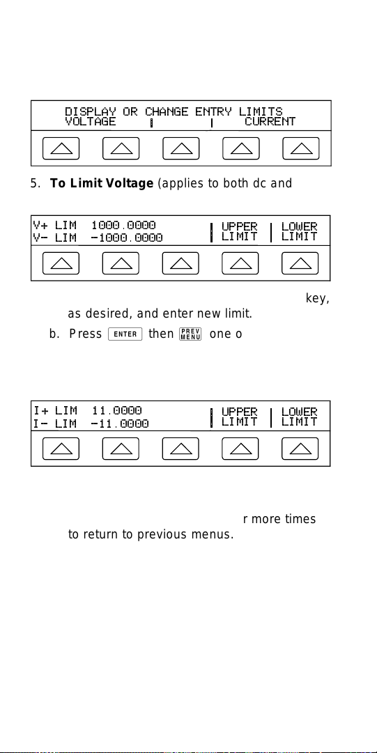
4. Press softkey SET LIMITS to open set limits
menu.
DISPLAY OR CHANGE ENTRY LIMITS
VOLTAGE
CURRENT
5. To Limit Voltage (applies to both dc and ac
voltages) Press softkey under VOLTAGE.
V+ LIM 1000.0000
V- LIM -1000.0000
UPPER
LIMIT
LOWER
LIMIT
a. Press “Upper Limit” or “Lower Limit” softkey,
as desired, and enter new limit.
b. Press E then P one or more times
to return to previous menus.
6. To Limit Current (applies to both dc and ac
currents) Press softkey under CURRENT.
I+ LIM 11.0000
I- LIM -11.0000
UPPER
LIMIT
LOWER
LIMIT
a. Press “Upper Limit” or “Lower Limit” softkey,
as desired, and enter new limit.
b. Press E then P one or more times
to return to previous menus.
51
Page 54

52
 Loading...