

Page 1

54200
®
TV Signal Generator
Users Manual
4822 872 10182
November 1996, Rev. 4 4/98
© 1996 Fluke Corporation, All rights reserved. Printed in the Netherlands.
All product names are trademarks of their respective companies.
Page 2

Page 3

Limited Warranty & Limitation of Liability
Each Fluke product is warranted to be free from defects in material and workmanship
under normal use and service. The warranty period is one year and begins on the date of
shipment. Parts, product repairs and services are warranted for 90 days. This warranty
extends only to the original buyer or end-user customer of a Fluke authorized reseller,
and does not apply to fuses, disposable batteries or to any product which, in Fluke's
opinion, has been misused, altered, neglected or damaged by accident or abnormal
conditions of operation or handling. Fluke warrants that software will operate
substant ially in accordan ce with its funct ional specificat ions for 90 days and that it has
been properly recorded on non-defective media. Fluke does not warrant that software will
be error free or operate without interruption.
Fluke authorized resellers shall extend this warranty on new and unused products to enduser customers only but have no authority to extend a greater or different warranty on
behalf of Fluke. Warranty support is available if product is purchased through a Fluke
authorized sales outlet or Buyer has paid the applicable international price. Fluke
reserves the right to i nvoi ce B uyer for i m port ati on cos t s of repair/replacement parts when
product purchased in one country is submitted for repair in another country.
Fluke's warranty obligation is limited, at Fluke's opinion, to refund of the purchase price,
free of charge repair, or replacement of a defect ive product whi ch is retu rned to an Fl uke
authorized service center within the warranty period.
To obtain warranty service, contact your nearest Fluke authorized service center or send
the product, with a description of the difficulty, postage and insurance prepaid (FOB
Destination), to the nearest Fluke authorized service center. Fluke assumes no risk for
damage in transit. Following warranty repair, the product will be returned to Buyer,
transportation prepaid (FOB Destination). If Fluke determines that the failure was caused
by misuse, alteration, accident or abnormal condition of operation or handling, Fluke
will provide an estimate of repair costs and obtain authorization before commencing the
work. Following repair, the product will be returned to the Buyer transportation prepaid
and the Buyer will be billed for the repair and return transportation charges (FOB
Shipping Point).
THIS WARRANTY IS BUYER'S SOLE AND EXCLUSIVE REMEDY AND IS IN
LIEU OF ALL OTHER WARRANTIES , EXPRES S OR IMPLIED, INCLUDING BUT
NOT LIMITED TO ANY IMPLIED WARRANTY OF MERCHANTABILITY OR
FITNESS FOR A PART ICULAR PURP OSE. FLUKE S HALL NOT BE LIABLE FOR
ANY SPECIAL, INDIRECT, INCIDENTAL OR CONSEQUENTIAL DAMMAGES
OR LOSSES, INCLUDING LOSS OF DATA, WHETHER AR ISING F ROM BR EACH
OF WARRANTY OR BASED ON CONTRACT, TORT, RELIANCE OR ANY
OTHER THEORY.
Since some countries or states do not allow limitation of the term of an implied warranty,
or exclusion or limitation of incidental or consequential damages, the limitations and
exclusions of this warranty may not apply to every buyer. If any provision of this
Warranty is held invalid or unenforceable by a court of competent jurisdiction, such
holding will not affect the validity or enforceability of any other provision.
Fluke Corporation Fluke Industrial B.V.
P.O. Box 9090 P.O. Box 90
Everett, WA 7600 AB Almelo
98206-9090 The Netherlands
USA
Page 4

Service Centers
To locate a n aut horized service center, visit us on the World W ide Web :
http://www.fluke.com
or call Flu ke u sing any of the phone number s listed b elow:
+1-888-993-5853 in U.S.A. and Canada
+31-402-675-200 in Europe
+1-425-446-5500 from other countries
Page 5

DECLARATION OF CONFORMITY
for
Fluke
TV Signal Generator
54200
Manufacturer
Fluke Industrial B.V.
P.O. Box 90
7600 AB
Almelo
The Netherlands
Statement of Conformity
Based on test results using appropriate standards, the product is in conformity with
Electromagnetic Compatibility Directive 89/336/EEC
Low Voltage Directive 73/23/EEC
Sample tests
Standards used:
EN 55011 (1992)
Radio Frequency Product-Family Emission Standard
EN 50082-1 (1992)
Electromagnetic Compatibility; Generic Immunity Standard:
IEC 801-2 (1984), IEC 801-3 (1984), IEC 801-4 (1988)
EN61000-4-2 (1995), EN61000-4-8(1993), ENV50140(1993)
EN 61010-1 (1994)+ A2 (1995)
Safety Requirements for Electrical Equipment for Measurement Use
The tests have been performed in a typical configuration.
This Conformity is indicated by the symbol
, i.e. “Conformité européenne”.
Page 6

Page 7

Table of Contents
Chapter Title Page
1 Installation and Safety Instructions ................................................... 1-1
Shipment Note ................................................................................................. 1-5
Initial Inspection............................................................................................... 1-5
Available built-in options Fluke 54200............................................................. 1-5
Introduction...................................................................................................... 1-9
Safety Instructions............................................................................................ 1-9
Maintenance and Repair............................................................................... 1-9
Grounding (Earthing)................................................................................... 1-9
Power Cable, Line Voltage Range, and Fuses............................................... 1-10
Operating Position of the Instrument ................................................................ 1-11
Radio Interference Suppression ........................................................................ 1-11
Isolation Transformer....................................................................................... 1-11
Instrucciones de instalación y de seguridad....................................................... 1-13
Instrucciones de seguridad................................................................................ 1-13
Mantenimiento y reparación......................................................................... 1-13
Puesta a tierra............................................................................................... 1-13
Cable de conducción eléctrica, rango de tensiones de la linea y fusibles ....... 1-14
Posición de uso del instrumento ....................................................................... 1-15
Supresión de radiointerferencias....................................................................... 1-15
Transformador de aislamiento........................................................................... 1-15
Istruzioni di installazione e di sicurezza............................................................ 1-17
Istruzioni di sicurezza....................................................................................... 1-17
Manutenzione e riparazione.......................................................................... 1-17
Messa a terra................................................................................................ 1-17
Cavo elettrico, zona della tensione di rete et fusibili..................................... 1-18
Posizione di uso dell’apparecchio..................................................................... 1-19
Schermatura contro i radiodisturbi.................................................................... 1-20
Trasformatore di separazione............................................................................ 1-20
Opstellings- en veiligheidsinstructies................................................................ 1-21
Veiligheidsinstructies....................................................................................... 1-21
Onderhoud en reparatie ................................................................................ 1-21
i
Page 8

54200
Users Manual
Aarding........................................................................................................ 1-21
Stroomkabel, netspanningsgebied en zekeringen .......................................... 1-22
Bedrijfsstand van het toestel............................................................................. 1-23
Ontstoring radio-interferentie............................................................................ 1-24
Scheidingstransformator................................................................................... 1-24
Inledande anvisningar och säkerhetsanvisningar ............................................... 1-25
Säkerhetsanvisningar........................................................................................ 1-25
Underhåll och reparation .............................................................................. 1-25
Jordning....................................................................................................... 1-25
Nätkabel, nätspänningsområde och säkringar................................................ 1-26
Instrumentets driftsläge .................................................................................... 1-27
Radio-avstörning.............................................................................................. 1-27
Skiljetransformator........................................................................................... 1-27
2 Main Features....................................................................................... 2-1
Introduction...................................................................................................... 2-3
Main Features................................................................................................... 2-3
3 Getting Started..................................................................................... 3-1
Introduction...................................................................................................... 3-3
Getting Started ................................................................................................. 3-3
General Information..................................................................................... 3-3
Turning the Instrument on............................................................................ 3-3
Self-test Routine............................................................................................... 3-3
Brief Checking Procedure................................................................................. 3-4
Test Equipment:........................................................................................... 3-4
Instrument Settings and Checks.................................................................... 3-4
Operation and Application................................................................................ 3-13
Control Elements, Display and Connectors................................................... 3-13
Front Panel .............................................................................................. 3-13
Rear Panel................................................................................................ 3-17
4 How to Use the Instrument.................................................................. 4-1
Introduction...................................................................................................... 4-3
Operating via Keyboard.................................................................................... 4-3
General Information..................................................................................... 4-3
Display .................................................................................................... 4-3
Keyboard ................................................................................................. 4-6
Instrument Settings ...................................................................................... 4-7
TV Standard............................................................................................. 4-7
Video Settings.......................................................................................... 4-10
Sound Settings......................................................................................... 4-12
Teletext, VPS, PDC, CC, and WSS.......................................................... 4-14
Vision Carrier Frequency Settings (RF Carrier)........................................ 4-15
Vision Carrier Level Setting (RF Level)................................................... 4-18
Video Amplitude Setting.......................................................................... 4-22
Chroma Amplitude Setting....................................................................... 4-26
Test Patterns ............................................................................................ 4-30
Storing and Recalling of Settings ................................................................. 4-35
Storing of Instrument Settings.................................................................. 4-35
Recalling of Instrument Settings .............................................................. 4-37
Digital Data and Text............................................................................... 4-39
ii
Page 9

Contents
Description and Applications of the Test Patterns............................................. 4-40
Circle ........................................................................................................ 4-42
Center Cross with Border Castellations ........................................................ 4-43
Dots ........................................................................................................ 4-45
Crosshatch ................................................................................................... 4-46
Checkerboard............................................................................................... 4-47
White Pattern ............................................................................................... 4-48
Multiburst.................................................................................................... 4-48
Greyscale ..................................................................................................... 4-49
DEM Pattern................................................................................................ 4-49
DEM 1 (PAL).......................................................................................... 4-49
DEM 1 (NTSC)........................................................................................ 4-51
DEM 1 (SECAM).................................................................................... 4-52
DEM 2 (PAL).......................................................................................... 4-53
DEM 2 (NTSC)........................................................................................ 4-53
DEM 2 (SECAM).................................................................................... 4-54
Purity ........................................................................................................ 4-55
PLUGE........................................................................................................ 4-56
Color Bar..................................................................................................... 4-57
Full Field Color Bar................................................................................. 4-57
Split Field Color Bar................................................................................ 4-58
SMPTE Color Bar.................................................................................... 4-59
Horizontal Color Bar................................................................................ 4-60
Color Temperature Adjustment .................................................................... 4-60
VCR Test..................................................................................................... 4-62
VCR 1 .................................................................................................... 4-62
VCR 2 .................................................................................................... 4-63
Standard Resolution Test ......................................................................... 4-64
High Resolution Test ............................................................................... 4-64
Writing Current Adjustment..................................................................... 4-64
Digital Scan Test.......................................................................................... 4-64
ADC Check 1........................................................................................... 4-65
ADC Check 2........................................................................................... 4-66
Moving Block.......................................................................................... 4-67
Progressive Scan Check 1 ........................................................................ 4-67
Progressive Scan Check 2 ........................................................................ 4-68
Progressive Scan Check 3 ........................................................................ 4-68
DIVERSE .................................................................................................... 4-69
EHT Test ................................................................................................. 4-69
IRS17 .................................................................................................... 4-70
Combined Test Patterns................................................................................ 4-71
CIRCLE................................................................................................... 4-71
Twofold Combinations of Patterns........................................................... 4-71
Threefold Combinations of Patterns......................................................... 4-73
Fourfold Combinations of Patterns........................................................... 4-73
Insertion-Reference Signal (IRS).................................................................. 4-74
(continued)
5 Function Reference ............................................................................. 5-1
TELETEXT...................................................................................................... 5-3
General ........................................................................................................ 5-3
UK-Teletext............................................................................................. 5-3
TOP (Table of Pages)............................................................................... 5-3
FLOF (Full Level-One Features) / FASTEXT.......................................... 5-5
VPT (Video Recorder Programming by Teletext)..................................... 5-5
iii
Page 10

54200
Users Manual
Video Recorder Programming by Teletext with PSF ................................ 5-7
Contents of Teletext Pages TOP/FLOF .................................................... 5-9
DIDON ANTIOPE Teletext ......................................................................... 5-10
Contents of DIDON ANTIOPE Text Pages.............................................. 5-10
Operating................................................................................................. 5-12
Checking and Adjusting........................................................................... 5-13
Wide Screen Signalling (WSS)......................................................................... 5-14
General ........................................................................................................ 5-14
Operating................................................................................................. 5-15
WSS Auto Mode...................................................................................... 5-16
WSS Manual Mode.................................................................................. 5-17
Status Bits Transmission Scheme for Wide Screen Signalling.................. 5-18
Programming the Real Time Clock................................................................... 5-20
PDC and VPS................................................................................................... 5-22
General ........................................................................................................ 5-22
PDC Description.......................................................................................... 5-22
Operating................................................................................................. 5-23
VPS Description........................................................................................... 5-26
Operating................................................................................................. 5-27
Data Format of Programme Delivery Data in the TV Line 16................... 5-30
CLOSED CAPTION (CC) ............................................................................... 5-32
General ........................................................................................................ 5-32
Operating................................................................................................. 5-34
Memory Contents .................................................................................... 5-35
Analog Mono Sound ........................................................................................ 5-38
General ........................................................................................................ 5-38
Operating................................................................................................. 5-38
Analog Stereo/Dual Sound ............................................................................... 5-39
General ........................................................................................................ 5-39
Operating................................................................................................. 5-40
NICAM Sound................................................................................................. 5-42
The NICAM-728 Transmission Mode...................................................... 5-42
Operating................................................................................................. 5-44
Applications............................................................................................. 5-46
Test functions .......................................................................................... 5-46
BTSC Sound.................................................................................................... 5-48
General ........................................................................................................ 5-48
Definitions............................................................................................... 5-50
Operating................................................................................................. 5-50
Explanations of BTSC Test Modes .......................................................... 5-53
Applications............................................................................................. 5-54
Recommendations.................................................................................... 5-55
Sound Operating Modes................................................................................... 5-56
External Modulation......................................................................................... 5-60
External Video Modulation .......................................................................... 5-60
Operating................................................................................................. 5-61
External Sound Modulation.......................................................................... 5-61
Operating................................................................................................. 5-63
Synchronization Outputs and Triggering ...................................................... 5-64
Operating Hints, Out of Range and Error Messages.......................................... 5-65
Operating Hints............................................................................................ 5-65
Out of Range Messages................................................................................ 5-65
Error Messages............................................................................................. 5-66
Remote Control Specific Error Messages ..................................................... 5-66
iv
Page 11

Contents
6 Remote Control.................................................................................... 6-1
Introduction...................................................................................................... 6-3
IEEE-488 Interface........................................................................................... 6-3
Instrument Address ...................................................................................... 6-3
Interface Functions....................................................................................... 6-6
RS-232 Interface .............................................................................................. 6-7
Instrument Configuration ............................................................................. 6-7
Interface Functions and Wiring..................................................................... 6-11
Interface Functions....................................................................................... 6-12
Remote Control Commands ............................................................................. 6-13
Program Message Syntax ............................................................................. 6-13
Message Terminator..................................................................................... 6-13
Service Request (SRQ) and Status Registers................................................. 6-14
54200 ‘Standard Event Status Register’.................................................... 6-15
Common Commands and Queries (IEEE-488.2)........................................... 6-16
System Data............................................................................................. 6-16
Internal Operations................................................................................... 6-17
Synchronization....................................................................................... 6-19
Status and Event ...................................................................................... 6-20
Save and Recall Instrument Settings......................................................... 6-21
Device Specific Messages ............................................................................ 6-21
Vision Carrier .......................................................................................... 6-22
TV-System............................................................................................... 6-23
Video .................................................................................................... 6-25
Sound .................................................................................................... 6-31
Digital Services........................................................................................ 6-35
Miscellaneous commands......................................................................... 6-39
Device Setting Queries............................................................................. 6-40
Programming Examples ................................................................................... 6-43
Example for the IEEE-488 Interface............................................................. 6-43
Example for the RS-232 Interface................................................................. 6-46
Error Messages................................................................................................. 6-50
Conversion Table for the PM 5415/18 Command Set to 54200 Commands...... 6-51
(continued)
7 Specifications ...................................................................................... 7-1
Safety and EMC Requirements......................................................................... 7-3
Performance Characteristics and Specifications ................................................ 7-3
Video and RF................................................................................................... 7-4
Outputs ........................................................................................................ 7-4
CVBS Video............................................................................................ 7-4
CVBS SYNC, LINE SYNC and FIELD Synchronization......................... 7-4
EURO AV Control Voltages.................................................................... 7-4
Terrestrial RF Carrier............................................................................... 7-5
Video Modulation.................................................................................... 7-6
Inputs ........................................................................................................ 7-6
Video IN.................................................................................................. 7-6
Video ........................................................................................................ 7-7
Synchronization....................................................................................... 7-7
Luminance............................................................................................... 7-7
Chrominance............................................................................................ 7-7
Patterns.................................................................................................... 7-8
Sound ............................................................................................................ 7-10
Outputs ........................................................................................................ 7-10
Sound Carrier........................................................................................... 7-10
v
Page 12

54200
Users Manual
Audio and Euro AV ................................................................................. 7-10
BTSC MPX and FM Stereo Pilot............................................................. 7-10
NICAM Data and NICAM Clock............................................................. 7-11
Inputs ........................................................................................................ 7-11
Audio, Euro AV and MTS Multiplex....................................................... 7-11
Mono ........................................................................................................ 7-11
Sound Carrier........................................................................................... 7-11
Modulation .............................................................................................. 7-12
Stereo /Dual................................................................................................. 7-12
Sound Carrier 1........................................................................................ 7-12
Sound Carrier 2........................................................................................ 7-12
Modulation .............................................................................................. 7-13
Identification/Subcarrier........................................................................... 7-13
NICAM Stereo............................................................................................. 7-13
Sound Carrier 1........................................................................................ 7-13
Sound Carrier 2........................................................................................ 7-14
Modulation .............................................................................................. 7-14
BTSC Stereo................................................................................................ 7-14
Sound Carrier........................................................................................... 7-14
Modulation .............................................................................................. 7-15
Identification............................................................................................ 7-15
Digital Services................................................................................................ 7-16
Wide Screen Signalling (WSS)..................................................................... 7-16
Teletext DIDON ANTIOPE (CCIR System A)............................................. 7-16
Teletext UK (CCIR System B)..................................................................... 7-17
PDC ........................................................................................................ 7-17
VPS ........................................................................................................ 7-17
Closed Caption............................................................................................. 7-18
RGB, YC (S-VHS/Hi-8), YCrCb Outputs ........................................................ 7-19
RGB Outputs ............................................................................................... 7-19
YC Outputs.................................................................................................. 7-19
YCrCb Outputs............................................................................................ 7-19
Feedthrough Connection .............................................................................. 7-20
IEEE-488 and RS-232 Interface........................................................................ 7-20
IEEE-488 Interface....................................................................................... 7-20
RS-232 Interface .......................................................................................... 7-20
General Specifications...................................................................................... 7-21
Environmental Conditions............................................................................ 7-21
Power Requirements .................................................................................... 7-22
Dimensions and Weight ............................................................................... 7-22
Accessories ...................................................................................................... 7-23
Standard....................................................................................................... 7-23
Optional....................................................................................................... 7-24
8 Brief Functional Test........................................................................... 8-1
Brief Functional Test........................................................................................ 8-3
Introduction.................................................................................................. 8-3
Recommended Test Equipment.................................................................... 8-3
Self-Test Routine ......................................................................................... 8-4
Function Verification........................................................................................ 8-5
TV Standard PAL......................................................................................... 8-5
Video Part, using RF Connection............................................................. 8-5
Video Part, using Y/C Connection (S-VHS, Hi-8) .................................... 8-7
Sound Part ............................................................................................... 8-8
vi
Page 13

Contents
Teletext, VPS, PDC, and WSS (Digital Services)..................................... 8-12
Wide Screen Signalling Bits (WSS .......................................................... 8-14
TV Standard NTSC...................................................................................... 8-15
Video Part, using RF Connection............................................................. 8-15
Video Part, using Y/C Connection (S-VHS, Hi-8) .................................... 8-17
Sound Part ............................................................................................... 8-18
Closed Caption (Digital Service CC)........................................................ 8-21
TV Standard SECAM................................................................................... 8-23
Video Part, using RF Connection............................................................. 8-23
Video Part, using Y/C Connection (S-VHS, Hi-8) .................................... 8-25
Sound Part ............................................................................................... 8-26
Teletext, VPS, PDC, and WSS (Digital Services)..................................... 8-29
Appendices
A TV Systems Used in Various Countries ............................................... A-1
B VHF/UHF-Channel Frequencies for Different TV Systems.................. B-1
C Default Settings for Countries.............................................................. C-1
D Spectras of TV Audio Systems............................................................. D-1
E Nomenclature of Color Bar Signals...................................................... E-1
F Menu Trees.......................................................................................... F-1
G Pattern Popup Menus........................................................................... G-1
(continued)
Index
vii
Page 14

Page 15

List of Tables
Table Title Page
1-1. Display Indication of built-in Options.................................................................. 1-8
1-2. Delivered Power Cable........................................................................................ 1-10
1-3. Cable suministrado.............................................................................................. 1-14
1-4. Cavo di alimentatione fornito in dotazione........................................................... 1-18
1-5. Meegelverde netkabel.......................................................................................... 1-22
1-6. Medleverera nätkabel........................................................................................... 1-26
3-1. EURO AV IN...................................................................................................... 3-19
3-2. EURO AV OUT.................................................................................................. 3-19
3-3. Y/C OUT............................................................................................................. 3-19
4-1. Circle .................................................................................................................. 4-42
4-2. Center Cross........................................................................................................ 4-44
4-3. Dots..................................................................................................................... 4-45
4-4. Crosshatch........................................................................................................... 4-47
4-5. PLUGE ............................................................................................................... 4-56
4-6. Full Field Color Bar ............................................................................................ 4-57
4-7. Color Temperature Adjustment............................................................................ 4-60
4-7. Color Temperature Adjustment............................................................................ 4-61
4-8. VCR 1................................................................................................................. 4-62
5-1. TOP Teletext Remote Control ............................................................................. 5-4
5-2. PDC/VPT Teletext Page 300, Transport Method A.............................................. 5-6
5-3. PDC/VPT Teletext Page 300, Transport Method B.............................................. 5-7
5-4. DIDON ANTIOPE Text Pages ............................................................................ 5-10
5-5. Teletext Systems and Modes................................................................................ 5-12
5-6. WSS Auto Mode ................................................................................................. 5-16
5-7. WSS Status Bits Transmission Scheme ............................................................... 5-18
5-8. VPS Information ................................................................................................. 5-26
5-9. Data Format of Programme Delivery Data in the TV Line 16 .............................. 5-30
5-9. Data Format of Programme Delivery Data in the TV Line 16 (cont) .................... 5-31
5-10. Closed Caption Field Packets .............................................................................. 5-33
5-11. Analog Stereo/Dual Audio Signals, Systems B/G and D/K.................................. 5-39
5-12. Analog Stereo/Dual Audio Signals, System Mk (Korean Stereo) ......................... 5-40
5-13. 54200 Analog Stereo/Dual Sound Systems.......................................................... 5-40
5-14. NICAM-728 Transmission, 54200 NICAM Systems........................................... 5-42
5-15. BTSC Sound Carrier Modulation Standards......................................................... 5-49
5-16. 54200 BTSC Sound Systems............................................................................... 5-50
ix
Page 16

54200
Users Manual
5-17. Sound Operating Modes ...................................................................................... 5-56
5-18. Sound Operating Modes (cont)............................................................................ 5-57
5-18. Sound Operating Modes (cont)............................................................................ 5-58
5-18. Sound Operating Modes (cont)............................................................................ 5-59
5-18. External Video Modulation Modes...................................................................... 5-60
5-19. External Sound Mode.......................................................................................... 5-62
6-1. Fluke 54200 'Status Byte Register'....................................................................... 6-14
6-2. Instrument Default Settings after Reset (*RST) ................................................... 6-17
6-3. Telephone Country Code..................................................................................... 6-23
6-4. Conversion Table ................................................................................................ 6-51
x
Page 17

Chapter 1
Installation and Safety Instructions
Title Page
Shipment Note ................................................................................................. 1-5
Initial Inspection............................................................................................... 1-5
Available built-in options Fluke 54200............................................................. 1-5
Introduction...................................................................................................... 1-9
Safety Instructions............................................................................................ 1-9
Maintenance and Repair............................................................................... 1-9
Grounding (Earthing)................................................................................... 1-9
Power Cable, Line Voltage Range and Fuses................................................ 1-10
Operating Position of the Instrument ................................................................ 1-11
Radio Interference Suppression ........................................................................ 1-11
Isolation Transformer....................................................................................... 1-11
Instrucciones de instalación y de seguridad....................................................... 1-13
Instrucciones de seguridad................................................................................ 1-13
Mantenimiento y reparación......................................................................... 1-13
Puesta a tierra............................................................................................... 1-13
Cable de conducción eléctrica, rango de tensiones de la linea y fusibles ....... 1-14
Posición de uso del instrumento ....................................................................... 1-15
Supresión de radiointerferencias....................................................................... 1-15
Transformador de aislamiento........................................................................... 1-15
Istruzioni di installazione e di sicurezza............................................................ 1-17
Istruzioni di sicurezza....................................................................................... 1-17
Manutenzione e riparazione.......................................................................... 1-17
Messa a terra................................................................................................ 1-17
Cavo elettrico, zona della tensione di rete et fusibili..................................... 1-18
Posizione di uso dell’apparecchio..................................................................... 1-19
Schermatura contro i radiodisturbi.................................................................... 1-20
Trasformatore di separazione............................................................................ 1-20
1-1
Page 18

54200
Users Manual
Opstellings- en veiligheidsinstructies............................................................... 1-21
Veiligheidsinstructies....................................................................................... 1-21
Onderhoud en reparatie................................................................................ 1-21
Aarding ....................................................................................................... 1-21
Stroomkabel, netspanningsgebied en zekeringen.......................................... 1-22
Bedrijfsstand van het toestel ............................................................................ 1-23
Otnstoring radio-interferentie........................................................................... 1-24
Scheidingstransformator .................................................................................. 1-24
Inledande anvisningar och säkerhetsanvisningar............................................... 1-25
Säkerhetsanvisningar ....................................................................................... 1-25
Underhåll och reparation.............................................................................. 1-25
Jordning ...................................................................................................... 1-25
Nätkabel, nätspänningsområde och säkringar............................................... 1-26
Instrumentets driftsläge.................................................................................... 1-27
Radio-avstörning ............................................................................................. 1-27
Skiljetransformator.......................................................................................... 1-27
1-2
Page 19
GB
Installation and Safety Instructions
Shipment Note
1
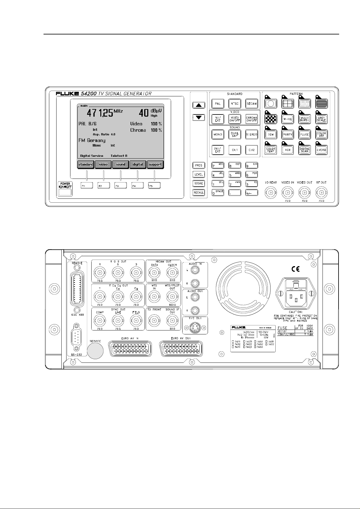
Figure 1-1. Front Panel
Figure 1-2. Rear Panel
1-3
Page 20

54200
Users Manual
1-4
Page 21
GB
Shipment Note
The following parts should be included in the shipment:
1 TV Signal Generator 54200
1 Users Manual (standard)
1 Power Cable (standard)
1 RF Cable BNC - IEC 169-2 male connector
1 IEC 162-2 male - F-male adapter
1 SCART - SCART cable
1 SCART - 3 x Cinch cable
1 Y/C cable (only with RGB option)
Initial Inspection
Check that the shipment is complete and note whether any damage has occurred during
transport. If the contents are incomplete or there is damage, file a claim with the carrier
immediately, and notify the Fluke Sales and Service organization to facilitate the repair
or replacement of the instrument.
Installation and Safety Instructions
Shipment Note
1
The functions of the instrument can be checked by using the Brief Functional Test in
Chapter 8 of this manual.
Available built-in options Fluke 54200
In addition the instruments shows the built-in options in a submenu on the display.
You can select this submenu via softkeys when the
If the display shows a different screen, press the
main screen appears or switch the instrument off, wait five seconds, and switch it on
again.
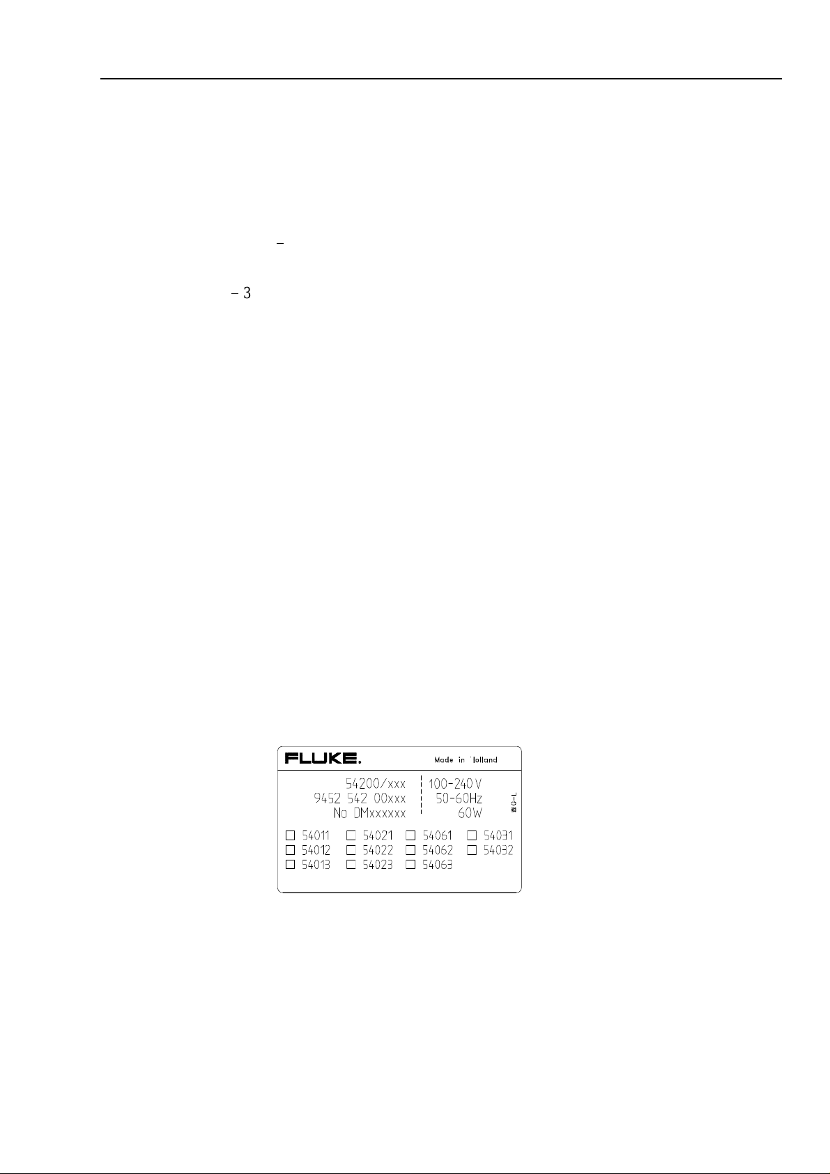
The built-in options are marked on the type plate on the rear of the instrument.
screen is displayed.
main
softkey (F5) so often until the
enter
1-5
Page 22
54200
Users Manual
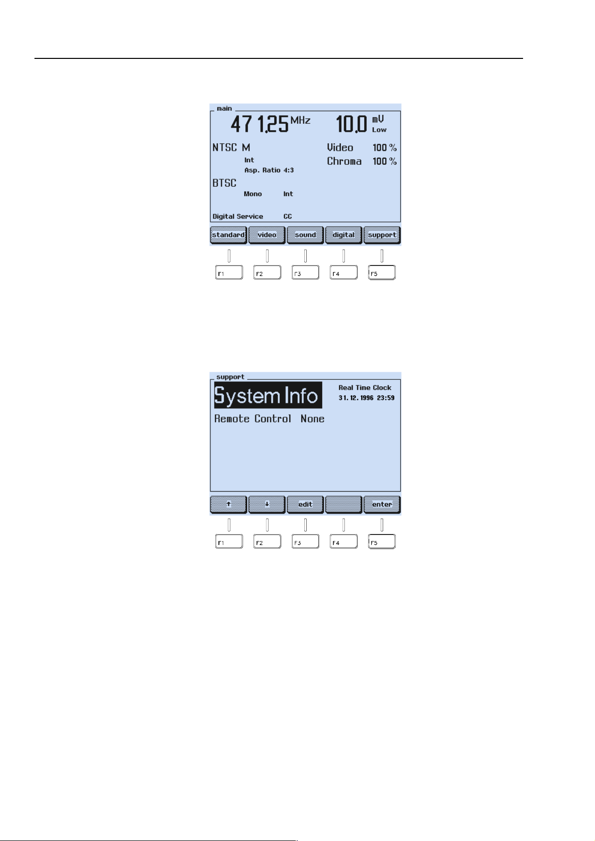
The instrument shows the
Press the
•
The display shows the
•
support
softkey (F5).
screen with the current settings:
main
Figure 1-3. Main Screen
support
submenu.
1-6
Press the
•
The display shows the
•
edit
Figure 1-4. Support Submenu
softkey (F3).
support system info
screen.
Page 23
GB
Installation and Safety Instructions
Available built-in options Fluke 54200
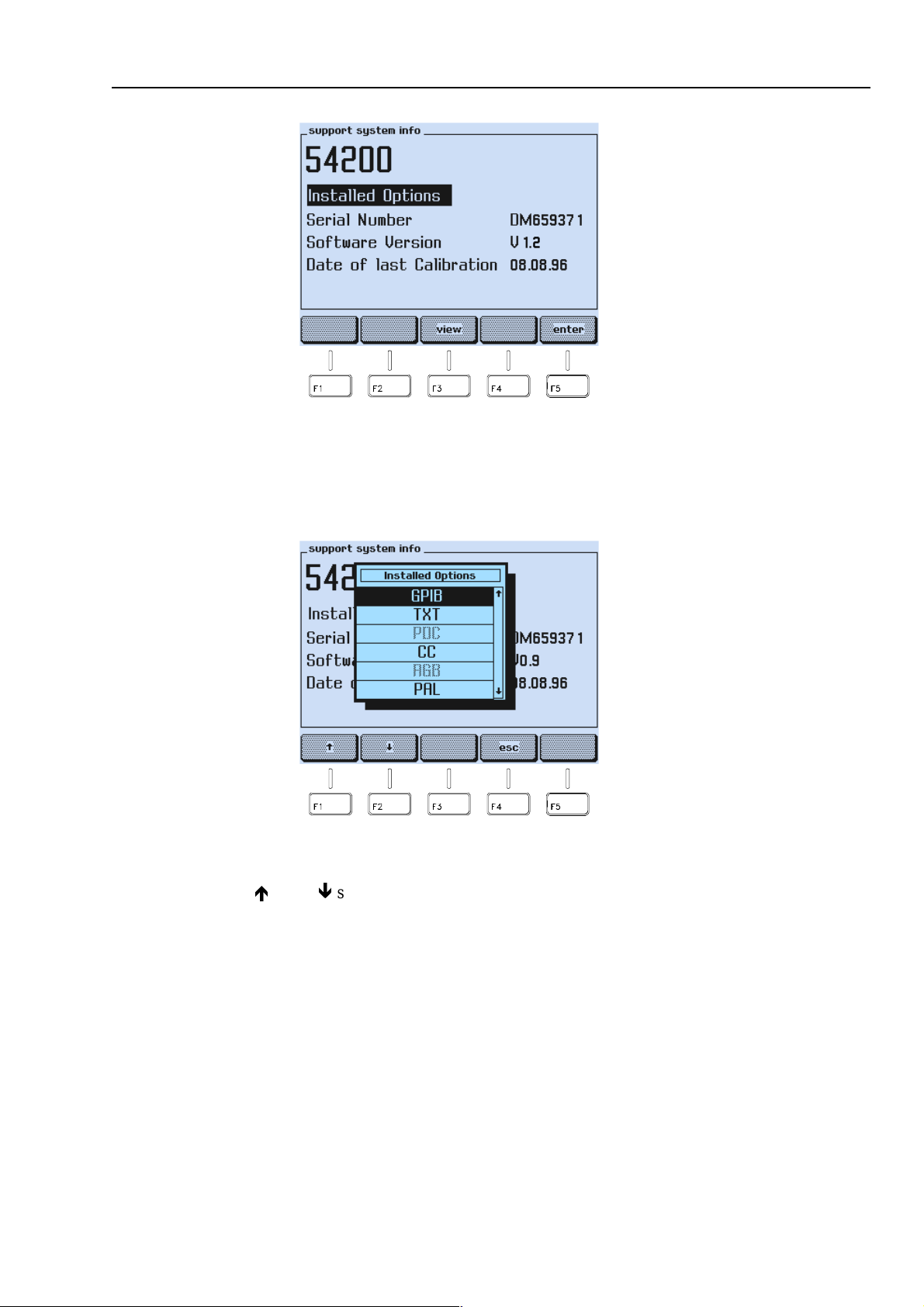
Figure 1-5. Support System Info Submenu
1
Press the
•
A popup menu appears, showing the options.
•
Use the é or the ê softkey (F1 or F2) to scroll through the table.
•
softkey (F3).
view
Figure 1-6. Popup Menu showing installed Options
Installed option
letters.
are displayed in
black letters, not installed
options are display
in grey
1-7
Page 24

54200
Users Manual
The meanings of the shortcuts are the following:
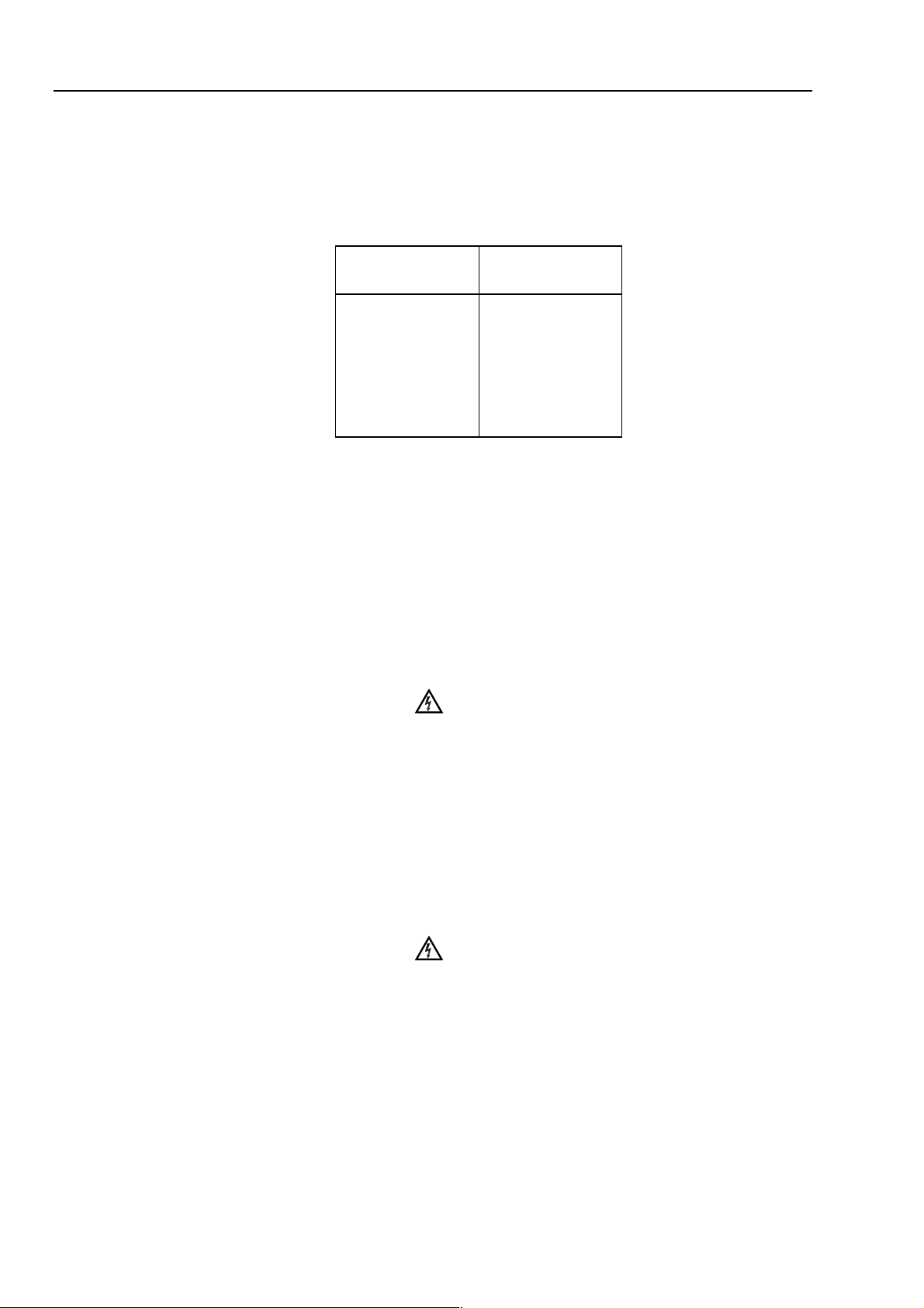
Table 1-1. Display Indication of built-in Options
54200
Display Indication
PAL
NTSC
SECAM
TXT
PDC
CC
RGB
GPIB
STEREO
NICAM
BTSC
Description Options
Type numbers
PAL Standard 54011
NTSC Standard 54012
SECAM Standard 54013
Teletext and Widescreen
Signalling Bits
PDC / VPS (only in combination
with option 54021)
Closed Caption 54023
RGB + YCrCb + YC 54031
IEEE / RS-232 Interface 54032
Mono Sound + Analog Stereo 54061
Mono Sound + NICAM Sound 54062
Mono Sound + BTSC Sound 54063
54021
54022
•
•
•
Press the
Press the
Press the
softkey (F4) to return to the
esc
softkey (F5) to return to the
enter
softkey (F5) again to return to the
enter
support system info
support
submenu.
screen.
main
submenu.
If you want additional options that are not built-in in your instrument at the moment,
please contact you local Fluke Sales Organization.
1-8
Page 25

GB
Introduction
This chapter should be read before unpacking, installing, and operating the instrument. It
describes grounding, power cables, and fuses.
It also contains the Installation and Safety Instructions in the following languages:
Spanish, Italian, Dutch and Swedish.
Safety Instructions
Upon delivery from the factory the instrument complies with the required safety
regulations, see Chapter 7. To maintain this condition and to ensure safe operation,
carefully follow the instructions below.
Maintenance and Repair
Failure and excessive stress:
If the instrument is suspected of being unsafe, remove it from operation immediately and
secure it against any unintended operation. The instrument is considered to be unsafe
when any of the following conditions exist:
Installation and Safety Instructions
Introduction
1
It shows physical damage.
•
It does not function.
•
It is stressed beyond the tolerable limits (e.g., during storage and transportation).
•
Disassembling the Instrument:
Calibration, maintenance, and repair of the instrument must be
performed only by trained personnel who are aware of the
hazards involved. To avoid electric shock, do not remove the
cover unless you are qualified to do so.
Before removing the cover, disconnect the instrument from all
power sources. The capacitors in the instrument may remain
charged for several seconds after all power has been
disconnected.
Grounding (Earthing)
Before any other connection is made, the instrument shall be connected to a protective
earth conductor using the three-wire power cable.
The power plug shall be inserted only into a grounded outlet. Do not defeat the
protective action by using of an extension cord without a grounded conductor.
Any interruption of the protective ground conductor inside or
outside the instrument or disconnection of the protective
ground terminal will make the instrument dangerous. Do not
Intentionally interrupt the protective ground conductor.
Warning
Warning
The circuit ground potential is applied to the external contacts of the BNC connectors
and is connected to the instrument case. The external contacts of the BNC connectors
must not be used to connect a protective conductor.
1-9
Page 26
54200
Users Manual
Power Cable, Line Voltage Range, and Fuses
Different power cables are available for the local line connectors. On delivery from the
factory the instrument is supplied with the ordered power cable:
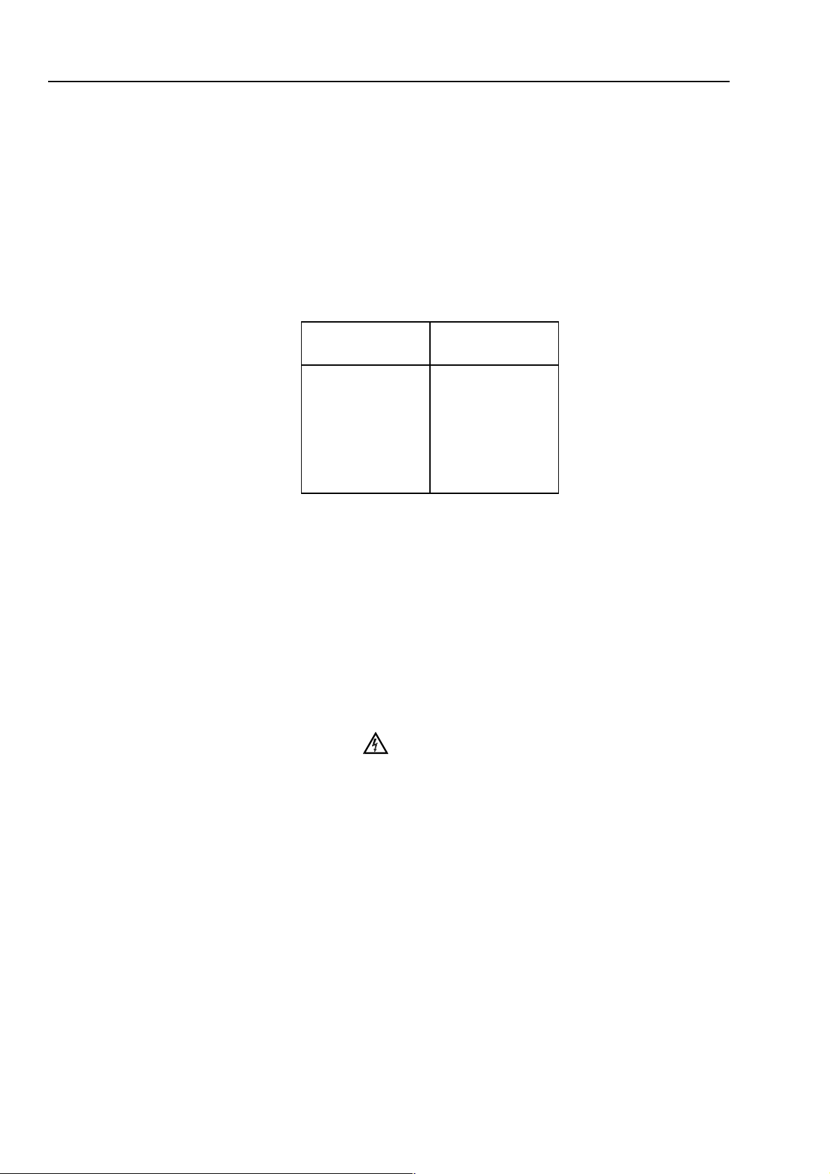
Table 1-2. Delivered Power Cable
Type No. Delivered
Power Cable
54200/XX1
54200/XX3
54200/XX4
54200/XX5
54200/XX8
Universal Europe
North America
England (UK)
Switzerland
Australia
Before plugging in the power cable, make sure that the instrument is suitable for the
correct line voltage.
Note
When the mains plug has to be adapted to the local situation, such
adaptation should be done by a qualified technician only.
The instrument has a switched-mode mains power supply that covers most nominal
voltage ranges in use: ac voltages from 100 to 240 V (r.m.s.). This obviates the need to
adapt to the local line voltage. The nominal line frequency is 50 to 60 Hz.
Warning
The instrument shall be disconnected from all voltage sources
when a fuse is to be renewed.
1-10
The fuses are located in a fuse holder of the input power module at the rear panel. When
the line fuses need replacing, proceed as follows:
disconnect the power cable from the power module.
•
press the clip of the fuseholder and pull out the holder, see illustration.
•
fit new fuses of the correct rating (according to IEC127 T1.6A or CSA/UL 198G
•
T1.6A) and refit the fuseholder.
Warning
To avoid fire hazards, make sure the instrument fuses are of
the type and current rating specified. Do not use repaired fuses
and/or short-circuited fuseholders. Do not defeat this important
safety feature.
Page 27

GB
Installation and Safety Instructions
Operating Position of the Instrument
1
Operating Position of the Instrument
The instrument can be operated on a horizontal surface in a flat position or in a sloping
position with the tilting feet folded down. Ensure that the ventilation holes are free of
obstruction. Do not position the instrument in direct sunlight or on any surface that
produces or radiates heat.
Radio Interference Suppression
Radio interference of the instrument is suppressed and checked carefully. If radio
frequency interferences occur in connection with other poorly suppressed instruments,
further suppression actions may be required.
Isolation Transformer
Because most MTV and CTV receivers are constructed with the chassis potentially 'live',
it is sensible precaution to power the receiver under test using a suitable isolating
transformer.
This permits direct connection of the television chassis to the earth terminals of any test
instrument thus providing a common signal path and reducing the risk of electric shock.
1-11
Page 28

54200
Users Manual
1-12
Page 29

E
Instrucciones de instalación y de seguridad
Instrucciones de instalación y de seguridad
Instrucciones de seguridad
El aparato sale de fábrica, técnicamente, en perfectas condiciones de seguridad (ver
cap. 7). Para que se conserven estas condiciones, y para evitar riesgos en el uso, hay que
seguir cuidadosamente las indicaciones siguientes.
Mantenimiento y reparación
Defectos y esfuerzos extraordinarios:
Si se piensa que el aparato ya no puede funcionar sin riesgo, hay que apagarlo y
asegurarse de que no se ponga en funcionamiento inadvertidamente. Este es el caso:
cuando el aparato presenta daños visibles,
•
cuando el aparato no funciona,
•
luego de haber sido sometido a esfuerzos excesivos de cualquier tipo (p.e.en el
•
almacenaje o el transporte) que sobrepasan los límites permitidos.
Installation and Safety Instructions
1
Abrir el aparato:
AI abrir algunas tapas o al desmontar piezas con herramientas
pueden quedar al descubierto partes bajo tensión eléctrica.
También puede haber tensión en los puntos de conexión.
Antes de abrir el aparato hay que desconectarlo de todas las
fuentes de alimentación.
Si es inevitable realizar un calibrado, mantenimiento o
reparacién con el aparato abierto que se encuentra bajo
tensión, sólo debe hacerio un técnico cualificado que conozca
los riesgos que existen. Los condensadores del aparato
pueden seguir estando cargados aùn cuando esté haya sido
desconectado de todas las fuentes de alimentación.
Puesta a tierra
Antes de hacer alguna conexión hay que conectar el aparato a un contacter protección
mediante el cable de alimentación de tres conductores.
El enchufe de la red debe ser insertado sólo en tomacorrientes con contacto de seguridad
de tierra.
No se deben anular estas medidas de seguridad, p.e. usando un cable de extensión sin
contactor de protección.
Advertencia
Advertencia
Toda interrupción del contactor de protección dentro o fuera
del aparato, o la separación de la conexión de la puesta
protectora peligrosa. Se prohíbe hacer la interrupción
expresamente.
1-13
Page 30
54200
Users Manual
Los contactos exteriores de los casquillos BNC tienen el potencial del neutro y están
conectados a la carcasa. La puesta a terra a través de los contactos exteriores de los
casquillos BNC es inadecuada.
Cable de conducción eléctrica, rango de tensiones de la linea y fusibles
Existen diferentes cables de conducción eléctrica para los terminales de la conexión a la
red. El instrumento se suministra desde fábrica con el cable de conducción eléctrica
pedido.
Table 1-3. Cable suministrado
Tipo de aparato Cable
suministrado
54200/XX1
54200/XX3
54200/XX4
54200/XX5
54200/XX8
Europa
Norteamérica
Inglaterra (U.K.)
Suiza
Australia
Antes de enchufar el cable de conducción eléctrica asegurarse que el instrumento esté
ajustado a la tensión correcta de la red.
Nota
Para evitar daños o peligros de muerte, toda modificación en los cables de
conducción eléctrica para adaptarlos a la corriente local deberá
ejecutarse por personal cualificado que tiene conocimientos suficientes de
los peligros existentes.
El instrumento tiene una conexión a la red conmutable que abarca los rangos de voltajes
nominales más usuales: tensiones alternas desde desde 100 hasta 240 (valor efectivo).
Con esto ya no es necesario adaptar la tensión de la red local. La frecuencia nominal de
la red es de 50 a 60 Hz.
Advertencia
Cuando se vaya a cambiar un fusible se ha de desconectar el
instrumento de toda fuente de voltaje.
1-14
Los fusibles están colocados en el portafusibles del módulo de potencia de entrada del
panel posterior. Para cambiar los fusibles del circuito proceder del siguiente modo:
desconectar el cable de corriente del módulo de potencia,
•
presionar la sujeción de apriete del portafusibles y sacar el portafusibles, ver la
•
figura,
colocar los nuevos fusibles con la potencia correcta (conforme a IEC127 T1,6A o
•
CSA/UL 198G T1,6A) y montar otra vez el portafusibles.
Page 31

Installation and Safety Instructions
E
Posición de uso del instrumento
1
Advertencia
Asegúrese que el nuevo fusible sea del tipo y de la potencia
especificada. El uso de fusibles reparados y/o el cortocircuito
de portafusibles está prohibido. No pase por alto esta
indicación de seguridad importante.
Posición de uso del instrumento
El instrumento se puede usar sobre una superficie plana en posición horizontal o
inclinada con el pie inclinable plegado hacia abajo. Si se cierra las patas de soporte et
aparato puede utilizarse en posición inclinada. Los datos técnicos del capituto 7 se
refieren a las posiciones indicadas. El aparato no se debe colocar nunca sobre una
superficie que
produzca o irradie calor ni exponerlo a los rayos directos del sol.
Supresión de radiointerferencias
En el aparato se han suprimido cuidadosamente todas las interferencias, habiéndose
sometido éste también a prueba. AI conectarlo a unidades básicas y a otras unidades
periféricas cuyas interferencias no se han suprimido correctamente, pueden generarse
interferencias que en algunos casos exigirán medidas adicionales para suprimirlas.
Transformador de aislamiento
Debido a quel el chasis de muchos televisores se encuentra bajo tensión, por motivos de
seguridad es necesario utilizar el receptor a probar a través de un transformador de
seccionamiento adecuado. Esto permite establecer un acoplamiento directo del chasis de
los televisores con la conexión al contactor de protección de algún aparto de prueba, con
Io que se reduce el riesgo de una descarga eléctrica.
1-15
Page 32

54200
Users Manual
1-16
Page 33

I
Istruzioni di installazione e di sicurezza
Istruzioni di sicurezza
L'apparecchio viene fornito dalla fabbrica perfettamente sicuro e funzionante dal punto di
vista tecnico (vedi Cap. 7). Per preservarlo in condizioni ottimali e garantirne un
corretto funzionamento, attenersi scrupolosamente alle seguenti istruzioni.
Manutenzione e riparazione
Funzionamento anomalo a sollecitazioni eccessive:
Qualora il funzionamento non risultasse regolare, spegnere subito l'apparecchio e
prevenirne ogni accensione accidentale. Le precauzioni di cui sopra vanno adottate nei
seguenti casi:
se l'apparecchio mostra dei danni visibili,
•
se l'apparecchio non funziona più,
•
se l'apparecchio è stato sottoposto a sollecitazioni (ad esempio durante il
•
magazzinaggio, il trasporto, ecc.) oltre i limiti di tolleranza ammessi.
Installation and Safety Instructions
Istruzioni di installazione e di sicurezza
1
Apertura dell'apparecchio:
Se i coperchi o alcune parti dell'apparecchio vengono rimossi
con appositi attrezzi, può darsi che risultino esposti dei
componenti interni sotto tensione. Anche i punti di
connessione possono essere sotto tensione. Prima di aprire
l'apparecchio occorre quindi disinnestarto dalle relative prese
di corrente.
Se fosse necessario eseguire intervenu di calibrazione,
manutenzione o riparazione con l'apparecchio aperto e sotto
tensione, rivolgersi a personale specializzato che conosca
bene i probabili rischi nelle procedure da adottare. Potrebbe
darsi che i condensatori dentro all'apparecchio siano ancora
carichi anche se l'apparecchio è stato disinnestato dalle
relative prese di corrente.
Messa a terra
Prima di eseguire un qualsiasi collegamento, mediante il cavo di alimentazione tripolare
l'apparecchio deve essere allacciato ad un conduttore di protezione.
La spina del cavo di alimentazione deve essere inserita soltanto in una presa munita di
contatto di messa a terra.
Questa norma resta comunque valida, anche se si utilizza un cavo di prolunga senza
conduttore di protezione.
Avvertimento
1-17
Page 34

54200
Users Manual
Avvertimento
E' estremamente pericoloso interrompere il conduttore di
protezione interno o esterno all'apparecchio o i contatti di
messa a terra. Evitare quindi di farlo intenzionalmente.
I contatti esterni delle prese BNC trasferiscono il potenziale del punto neutro del circuito
e sono collegate all'incvolucro dell'apparecchio. E' vietata la messa a terra di sicurezza
tramite i contatti esterni delle prese BNC.
Cavo elettrico, zona della tensione di rete et fusibili
Per i morsetti di allacciamento alla rete locale esistono differenti tipi di cavi. Se la
fornitura avviene dalla fabbrica, l’apparecchio viene già fornito con il cavo elettrico
ordinato.
Table 1-4. Cavo di alimentatione fornito in dotazione
Tipo de
apparecchio
54200/XX1
54200/XX3
54200/XX4
54200/XX5
54200/XX8
Cavo di
alimentatione
fornito in
dotazione
Europa
Nord America
Inghilterra (U.K.)
Svizzera
Australia
Prima di inserire il cavo elettrico, assicuratevi che l’apparecchio sia adatto alla tensione
corretta della rete.
Indicazione
Onde evitare il pericolo di ferimenti o di morte, la modifica al cavo
elettrico per l’adattamento del cavo alla corrente locale deve essere
eseguita solamente da personale del Service qualificato, poichè questo
conosce esattamente gli eventuali pericolo.
L’apparecchio è dotato di un allacciamento alla rete commutabile che comprende le zone
della tensione di rete più usuali: tensioni alternate da 100 a 240 V (valore effettivo). Per
questo motivo, non è necessario adattare la tensione della rete locale. La frequenza di rete
nominale è da 50 a 60 Hz.
1-18
Page 35

Installation and Safety Instructions
I
Posizione di uso dell’apparecchio
1
Avvertimento
Quando si sostituisce un fusibile, l’apparecchio deve essere
disinserito da ogni fonte di energia.
I fusibili si trovano nel portafusibili sul quadro posteriore del modulo della potenza di
entrata. Per sostituire i fusibili del circuito, procedere come segue:
staccare il cordone di alimentazione dal modulo di potenza;
•
premere il serraggio a morsetto del portafusibili ed estrarre il portafusibili, vedi
•
figura;
inserire nuovi fusibili badando che la potenza sia giusta (conformi a IEC127 T1,6A
•
oppure CSA/UL 198G T1,6A), e rimontare il portafusibili.
Avvertimento
Assicuratevi che i nuovi fusibili siano del tipo e della potenza
specificata. È vietato l’uso di fusibili riparati e/o il
cortocircuitare del portafusibili. Rispettate queste importanti
misure di sicurezza.
Posizione di uso dell’apparecchio
L’apparecchio può essere usato su una superficie orizzontale ed in posizione piana o in
posizione inclinata con il piede ribaltabile abbassato.Abbassando i piede di supporto, si
può utilizzare l'apparecchio in posizione inclinata. I dati tecnici riportati nel Capitolo 7
valgono per le posizioni indicate. L'apparecchio non deve essere mai collocato su una
superficie surriscaldabile o che produca irradiazioni, né essere esposto ai raggi diretti del
sole.
1-19
Page 36

54200
Users Manual
Schermatura contro i radiodisturbi
L'apparecchio è stato realizzato per garantire un funzionamento esente da interferenze. Se
viene utilizzato congiuntamente a unità base e unità periferiche non dotate delle stesse
protezioni, ne possono derivare interferenze che richiederanno ulteriori intervenu.
Trasformatore di separazione
Poiché il chassis di molti televisori è sottotensione, per motivi di sicurezza è necessario
utilizzare il ricevitore da testare tramite un trasformatore di separazione adatto. Ciò
permette di stabilire un collegamento diretto del chassis del televisore con la connessione
de conduttore di protezione di un apparechio di prova, in modo che venga ridotto il
rischio di una scossa elettrica.
1-20
Page 37

NL
Opstellings- en veiligheidsinstructies
Veiligheidsinstructies
Het apparaat heeft de fabriek in een onberispelijke veiligheidstechnische toestand
verlaten (zie hoofdstuk 7). Voor het behoud van deze toestand en het risicoloze gebruik
dienen de onderstaande instructies nauwkeurig te worden opgevolgd.
Onderhoud en reparatie
Storingen en uitzonderlijke omstandigheden
Wanneer verondersteld moet worden dat een risicoloos gebruik niet meer mogelijk is,
dient het apparaat buiten gebruik gesteld en tegen een ongewenst gebruik beveiligd te
worden. Deze situatie doet zich voor
wanneer het apparaat zichtbare beschadigingen vertoont,
•
wanneer het apparaat niet meer functioneert,
•
na blootstelling aan excessieve omstandigheden van welke aard dan ook (bij
•
voorbeeld bij opslag, transport) die de toelaatbare grenzen overschrijden.
Installation and Safety Instructions
Opstellings- en veiligheidsinstructies
1
Openen van het apparaat:
Aarding
Alvorens men een verbinding tot stand brengt, dient men het apparaat met behulp van
een drieaderige kabel met een veligheidsaarddraad te verbinden. De netsteker mag slechts
op een stopcontact met randaarde worden aangesloten. Deze veiligheidsmaatregel mag
niet onwerkzaam gemaakt worden, bij voorbeeld door het gebruik van een verlengsnoer
dat niet van een veiligheidsaarddraad voorzien is.
Waarschuwing
Bij het openen van afdekkingen of bij het met behulp van
gereedschap verwijderen van onderdelen, kan het risico van
contact met spanningvoerende delen ontstaan. Ook kan er
spanning op aansluitpunten aanwezig zijn. Het apparaat mag
pas geopend worden nadat het van alle spanningsbronnen
losgenomen is.
Wanneer ijk-, onderhouds- of herstelwerkzaamheden aan een
open en onder spanning staand apparaat onvermijdelijk zijn,
mogen deze slechts worden uitgevoerd door een vakman die
weet met welke gevaren dit gepaard gaat. In het apparaat
aanwezige condensators kunnen nog geladen zijn, ook
wanneer het apparaat van alle spanningsbronnen is
losgenomen.
1-21
Page 38

54200
Users Manual
Waarschuwing
Elke onderbreking van de beschermende aardleiding, hetzij
binnen of buiten het apparaat, of de scheiding ten opzichte van
de aardleiding zijn gevaarlijk. Een opzettelijke onderbreking is
verboden.
Op de externe contacten van de BNC-bussen is het schakelnulpunt-potentiaal aanwezig.
Deze contacten zijn met het huis verbonden. Een veiligheidsaarding via de externe
contacten van de BNC-bussen is niet toegestaan.
Stroomkabel, netspanningsgebied en zekeringen
Voor reeds aanwezige net-aansluitklemmen zijn verschillende stroomkabels beschikbaar.
In geval van levering af fabriek wordt het toestel afgeleverd met de door de klant
bestelde stroomkabel.
Table 1-5. Meegelverde netkabel
Type apparaat Meegelverde
netkabel
54200/XX1
54200/XX3
54200/XX4
54200/XX5
54200/XX8
Europa
Noord-America
Engeland (U.K.)
Zwitserland
Australië
Alvorens de stroomkabel in te pluggen, dient u te controleren, of het toestel voor de
gebruikte netspanning geschikt is.
Opmerking
Ter vermijding van letsel en dodelijke ongevallen mogen adapties aan de
stroomkabel ter aanpassing aan het plaatselijk stroomnet alleen door
gekwalificeerd service-personeel worden uitgevoerd, dat volledig op de
hoogte is van de hieraan verbonden gevaren.
Het toestel heeft een geschakelde netvoeding, die de meest gangbare netspanningen
afdekt: d.w.z. wisselspanningen van 100 tot 240 V (effectieve waarde). Hierdoor is
aanpassing van de plaatselijke netspanning overbodig. De nominale netfrequentie
bedraagt 50 tot 60 Hz.
1-22
Page 39

NL
Installation and Safety Instructions
Bedrijfsstand van het toestel
Waarschuwing
Wanneer een zekering vervangen moet worden, dient het
toestel van alle spanningsbronnen te worden losgekoppeld.
De zekeringen zitten in de zekeringshouder op het achterpaneel van het ingangsstroommoduul. Bij het vervangen van de kabelzekeringen als volgt te werk gaan:
stroomkabel van vermogensmoduul loskoppelen,
•
klembevestiging van de zekeringshouder indrukken en de houder uitnemen, zie
•
afbeelding,
nieuwe zekeringen met juiste sterkte (overeenkomstig IEC127 T1,6A o CSA/UL
•
198G T1,6A) plaatsen en de zekeringshouder weer monteren.
Waarschuwing
U dient ervoor te zorgen, dat de gebruikte reserve-zekeringen
van het voorgeschreven type zijn en berekend op de
voorgeschreven stroomsterkte. Het gebruik van gerepareerde
zekeringen en/of kortsluiten van smeltpatronen is verboden.
Verontachtzaam deze belangrijke veiligheidsinstructie in geen
geval!
1
Bedrijfsstand van het toestel
Het toestel kan op een horizontaal oppervlak in platte of schuine stand met neergeklapte
voet worden gebruikt. Wanneer de klapvoeten naar beneden geklapt zijn, kan het
apparaat in een schuingeplaatste positie gebruikt worden. De technische specificatie in
hoofdstuk 7 is van toepassing op de gespecificeerde gebruiksposities. Het apparaat nooit
installeren op een oppervlak dat warmte genereert of uitstraalt, en het evenmin aan
rechtstreekse zonnestraling blootstellen.
1-23
Page 40

54200
Users Manual
Ontstoring radio-interferentie
Wat radio-ontstoring betreft is het apparaat zorgvuldig ontstoord en gecontroleerd. Bij
het schakelen in combinatie met basisunits die niet correct onstoord zijn en met andere
perifere apparatuur, kan radiostoring optreden. In de desbetreffende gevallen maakt dit
aanvullende maatregelen op radio-ontstoringsgebied noodzakelijk.
Scheidingstransformator
Omdat het chassis van vele TV-apparaaten direct aan een kant van de netspanning
aangesloten is, is het noodzakelijk bij metingen een scheidingstransformator te
gebruiken. Dit moet uit het oogpunt van veiligheid. Deze transformator is aan te sluiten
tussen de netvoeding en het TV-toestel, en maakt het mogelijk het TV-chassis te aarden,
en met de aarde van een meetapparaat te verbinden, om ook daarmee een gevaarlijke
situatie te verhinderen.
1-24
Page 41

Installation and Safety Instructions
S
Inledande anvisningar och säkerhetsanvisningar
Inledande anvisningar och säkerhetsanvisningar
Säkerhetsanvisningar
Instrumentet har lämnat tillverkningen när det innehållsmässigt var i ett säkerhetstekniskt
gott skick (Se kap. 7). För att bibehålla detta skick och en riskfri drift måste man följa
nedanstående anvisningar noggrant.
Underhåll och reparation
Fel och ovanliga fröhållanden:
När det ser ut som om säkerhetsskyddet blivit nedsatt måste instrumentet sättas ur
funktion och säkerställas mot varje oavsiktlig handling. Detta uppstår när:
instrumentet visar en synlig skada,
•
instrumentet inte längre funktionerar,
•
efter olika slags exceptionella förhållanden (under t.ex. lagring och transport) som
•
överskridit tillåtna gränser.
1
Instrumentets öppnande:
Jordning
Innan du gjort någon koppling med de ingående förbindelserna, skall instrumentet
förbindas med en skyddande jordning genom den trekärniga huvudkabeln;
huvudstickkontakten får bara stickas in i en koppling som är försedd med en skyddande
jordning. Denna åtgärd får inte upphävas genom användning av en kopplingssladd som
inte har denna skyddande jordledning.
Varning
Vid öppnandet av instrumentet eller avlägsnande av delar med
verktyg kan strömförande delar friläggas och kopplingsbitar
kan vara strömförande. Före öppnandet måste instrumentet
avskiljas från alla strömkällor.
När kalibrering, underhåll eller reparation på ett öppnat
instrument som är strömförande inte går att undvika får det
bara utföras av kvalificerad personal som känner till faror och
säkerhetsåtgärder. Instrumentets kondensatorer kan vara
strömförande t.o.m. när instrumentet lösgjorts från alla
strömkällor.
Varning
Varje avbrott av den skyddande jordledningen såväl utanför
som invändigt i instrumentet gör förmodligen instrumentet
farligt. Medvetet avbrott är förbjudet.
Omkopplingsnollpunktspotentialen finns på den externa kontakten till BNC-uttaget.
Dessa kontakter är förbundna med höljet. En säkerhetsjordning via de externa
kontakterna till BNC-uttaget är inte tillåtet.
1-25
Page 42

54200
Users Manual
Nätkabel, nätspänningsområde och säkringar
Det finns nätkablar anpassade till olika länders nätuttag. Instrumentet kan beställas för
leverans med en av nedanstående kabeltyper.
Table 1-6. Medleverera nätkabel
Instrumenttyp Medleverera
nätkabel
54200/XX1
54200/XX3
54200/XX4
54200/XX5
54200/XX8
Europa
Nordamerika
Storbrittannien (U.K.)
Schweiz
Australien
Kontrollera att den lokala nätspänningen är lämpad för instrumentet, före anslutning av
nätkabeln.
Obs
För eventuellt utbyte av kontaktdon på den medlevererade sladden, anlita
endast en kvalificerad tekniker.
Apparaten kan anslutas till nätspänningar från 100 till 240 Veff, och frekvenser från 50
till 60 Hz, utan inställning av spänningsområde.
Varning
Vid byte av säkring ska instrumentet först kopplas bort från
nätspänningen.
Säkringarna finns i säkringshållaren vid nätspänningsintaget på instrumentets baksida.
Om säkringen behöver bytas, gör på följande sätt:
1-26
ta bort nätkabeln
•
tryck in klacken på säkringshållaren och dra ut hållaren, se bilden.
•
sätt i ny säkring (av rätt typ enligt IEC127 T1,6A eller CSA/UL 198G T1,6A) i
•
säkringshållaren och sätt tillbaka säkringshållaren.
Varning
Använd endast reservsäkringar av den specificerade typen och
strömstyrkan. Reparerade eller kortslutna säkringar får ej
användas. Ignorera inte dessa viktiga säkerhetsåtgärder.
Page 43

Installation and Safety Instructions
S
Instrumentets driftsläge
1
Instrumentets driftsläge
Instrumentet kan användas horisontalt eller, med fötterna utfällda, i en luttande position.
När de nedfällbara fötterna fällts nedåt kan instrumentet användas i ett snedplacerat läge.
Den tekniska specifikationen i kapitel 7 är tillämplig för de specificerade
användningslägena. Instrumenter får aldrig installeras på en yta som alstrar eller ustrålar
värme och inte heller utsättas för direkt solsken.
Radio-avstörning
När det gäller radio-avstörning är instrumentet omsorgsfullt avstört och kontrollerat. Vid
koppling i kombination med basisenheter som inte är riktigt avstörda och med annan
kring-utrustning kan det uppstå radiostörningar. Vid sådana fall är extra åtgärder för
radio-avstörning nödvändiga.
Skiljetransformator
Eftersom mänga tv-apparaters chassi befinner sig i samma fas, är det av säkerhetsskäl
absolut nödvändigt att köra den mottagare som skall testas över en lämplig
skiljetransformator. På så sätt är det möjligt att åstadkomma en direkt förbindelse mellan
tv-apparaternas chassi och skyddsledaranstutningen till någon som helst testapparat,
varigenom risken för elektrisk stöt minskas avsevärt.
1-27
Page 44

54200
Users Manual
1-28
Page 45

Chapter 2
Main Features
Title Page
Introduction...................................................................................................... 2-3
Main Features................................................................................................... 2-3
2-1
Page 46

Page 47

Introduction
This chapter describes the main features of the instrument, its functions, operating modes
and options.
Main Features
Main Features
Introduction
2
This chapter describes the
Depending on the ordered instrument different features may not be implemented.
This TV Signal Generator matc he s a ny de dic a te d se t of re quir e me nts, whethe r it is in R&D,
manufacturing, quality a ssurance, installation, servic e , and tr a ining.
The generator covers nearly all world-wide standards including PAL, NTSC, and
SECAM with their subsystems as well as sound standards and data transmission
standards.
The Fluke 54200 with its menu-driven control makes it easy for you to work with the
instrument and allows a large choice and configuration of the provided test signals. The
instrument offers the complete RF range from 32 MHz to 900 MHz, so covering the IF-,
VHF I-, VHF III-, S-, Hyper- and UHF-Band.
The test patterns a r e se le c ted using the PATTERN ke ypa d or a dditiona l sof t ke ys. Some test
patterns are offered in different versions or for different TV standards, for example, the Color
Bar, PLUGE, DEM (Demodulator) or VCR test. Some patter ns a r e of fe r e d with se le c ta ble
‘white’ or prima r y color signal levels. Up to f our f old te st pa tte r n c o mbina tions a r e se le c ta ble .
All test patterns ar e of fe r e d in the 16:9 a nd 4:3 pic tur e f or mat.
Up to 99 complete instrument se ttings c a n be stored and rec a lle d f or f a st a nd c onve nie nt
setup. A step function allows to move swif tly through the se que nc e of stor e d inf orma tion.
Furthermore, you have the advantage to recall TV system depending instrument settings for
20 different countr ie s inc luding sound systems, color sta nda r d, re sidua l c a rr ie r , group de la y
correction, and Te le te xt.
Fluke 54200 TV Signal Generator
with all options built in.
An
Insertion-Reference Signal
blanking interval in the TV line 17. The IRS is according to CCIR Rec. 473-5 and serves to
detect and corr e c t distor tion in TV signa ls.
The composite video signal of nomina l 1 V (pp) a t the VIDEO OUTPUT c a n be se t fr om 0 to
1.5 V.
The level of the c hr omina n c e signa l is se le c ta ble f r om 0% to 150% .
The maximum RF output signal of 10 mV or 100 mV can be a tte nua te d by mor e tha n 60 or
80 dB.
On the rear pa ne l the instru me nt off e r s dif f e re nt vide o outputs with
Y/C signals
For synchronization purpose , thre e outputs a r e a va ila ble : Composite , Line, and Field Sync.
The instrument offers the following sound systems:
Mono sound
•
Analog stereo sound
•
NICAM sound
•
BTSC/MTS sound
•
.
(IRS) is generate d f or PAL 625 line syste ms in the f ield-
RGB, YCrCb,
and
2-3
Page 48

54200
Users Manual
Mono sound is available for all TV subsystems. Different internal audio frequencies are
selectable.
Different analog Stereo sound systems are optional available, for example, for the
countries Germany (FM BG), Korea (FM Mk), and Czech Republic (FM DK).
NICAM and BTSC sound are options. NICAM is a digital sound system mainly used for
PAL B/G, PAL I, PAL D, and SECAM L. Three special test signals are available to
check NICAM equipment.
The BTSC/MTS sound system is selectable for NTSC M and PAL M. BTSC is mainly
used in the United States and Taiwan. Several specific test signals are included.
External sound modulation is possible for all sound systems except NICAM and BTSC
sound. For BTSC, an external MTS signal can be applied; so the instrument operates as
RF modulator.
The modulated sound carrier is available at the RF Output and Sound IF Output. The
NICAM signal is applied to the NICAM Output and the BTSC baseband spectrum to the
MTS Output at the rear.
Teletext and Wide Screen Signalling bits (WSS)
are available with both the PAL and
SECAM standard. The Teletext system is according to the WST Teletext standard and
includes both TOP and FLOF or Antiope. Automatically generated Wide Screen
Signalling bits in TV line 23 are bits to identify some transmission information, for
example, Aspect Ratio or Subtitling. Additionally the WSS bits are programmable.
Closed Captioning (CC)
is a subtitling system which is transmitted using either field of
line 21. In the Fluke 54200 Closed Caption and Text Service (T1 to T4) are available for
the TV systems NTSC, PAL 625 and 525 line systems, and SECAM.
The
VPS (Video Programming System) and PDC (Programme Delivery Control)
systems are used to synchronize a VCR recording with the actual broadcast transmission
(start and stop time). VPS is mainly used in Germany, Austria, and Switzerland, whereas
PDC is used in many other European countries.
VPS uses TV line 16 of the PAL transmission standard. The PDC data are transmitted
with the Teletext signal.
Remote control
is done either using the IEEE-488 or RS-232C Interface. The option
provides both methods, however, only one can be used at a time.
2-4
Page 49

Chapter 3
Getting Started
Title Page
Introduction...................................................................................................... 3-3
Getting Started ................................................................................................. 3-3
General Information..................................................................................... 3-3
Turning the Instrument on............................................................................ 3-3
Self-test Routine............................................................................................... 3-3
Brief Checking Procedure................................................................................. 3-4
Test Equipment............................................................................................ 3-4
Instrument Settings and Checks.................................................................... 3-4
Operation and Application................................................................................ 3-13
Control Elements, Display and Connectors................................................... 3-13
Front Panel .............................................................................................. 3-13
Rear Panel................................................................................................ 3-16
3-1
Page 50

Page 51

Introduction
This chapter starts with the general procedures and precautions necessary for operation
followed by a brief checking procedure. It contains a summary of controls and
connectors on the front and rear panels and the display.
Getting Started
General Information
This section outlines the procedure and precautions necessary for operation. It identifies
and briefly describes the functions of the front and rear panel controls and the display.
Turning the Instrument on
Before turning the instrument on, ensure that it has been
installed in accordance with the instructions in Chapter 1.
Warning
Getting Started
Introduction
3
After the instrument has been connected to the line voltage in accordance with
Chapter 1, it can be turned on by setting the
The specifications given in Chapter 7 of this manual are valid when the instrument is
installed in accordance with the instructions in Chapter 1 of this manual and after a
warm-up period of 30 minutes.
After turning the power off, wait at least 5 seconds before turning it on again. This
allows all power to completely discharge and the instrument to reset.
Self-test Routine
After power on, the instrument performs a self-test routine of the PROM, processor
RAM, stored instrument settings, calibration data, and available digital modules. After
approximately 2 seconds the generator automatically recalls its instrument state before
power off.
If a fault is found during the self-test this fault is indicated as follows,
for example:
POWER
switch on the front panel to
ON.
For detailed information, see the end of Chapter 5 ‘Operating Hints, Out of Range and
Error Messages’.
3-3
Page 52

54200
Users Manual
Brief Checking Procedure
This procedure checks the instrument functions with a minimum of steps. It is assumed
that the operator doing the test is familiar with the instrument and its specifications.
After POWER ON, the instrument is automatically set to the operating mode to which it
was set before POWER OFF.
Test Equipment
Multi-system TV
•
Instrument Settings and Checks
The display shows the last instrument settings before power off, for example:
3-4
•
Press the
Figure 3-1. Main Menu with Current Instrument Settings
standard
softkey (F1).
Page 53

A submenu with the selected country and its default settings appears, in this
•
example, United Kingdom.
Figure 3-2. Current Country with Video Standard and Sound System
Getting Started
Brief Checking Procedure
3
Press the
•
A popup menu with a pre-defined country list appears.
•
Select with the
•
your country is not listed, select a country that uses your or a similar video standard
and sound system.
softkey (F3).
edit
or ê softkey (F1 or F2) your country, for example, Germany. If
é
Figure 3-3. Popup Menu with the Pre-defined Country List
•
Press the
softkey (F5) to confirm your selection.
enter
3-5
Page 54

54200
Users Manual
The display shows the video standard and the sound system according to the selected
•
country.
Figure 3-4. Selected Country with Video Standard and Sound System
If your TV equipment does not support the TV system, select the required video
•
standard or sound system with the
FM Germany
Press the
•
Select the required standard or system with the
•
example,
Press the
•
Press the
•
.
softkey (F3).
edit
FM Mono
enter
enter
.
softkey (F5) to confirm your settings.
softkey (F5) again to return to the
or ê softkey (F1 or F2), for example,
é
or ê softkey (F1 or F2), for
é
menu.
main
3-6
Figure 3-5. Main Menu with Selected Settings
Check if the video and chroma amplitudes are set to 100%.
•
If not, press the
•
video
softkey (F2).
Page 55

Getting Started
Brief Checking Procedure
3
The display shows the
Figure 3-6. Video Submenu with Current Setting
Press the
•
A popup menu for numerical entries appears.
•
softkey (F3).
edit
submenu with the complete current settings:
video
•
•
•
•
•
•
Key in
1 0 0
Press the
Press the
Key in
1 0 0
Press the
Press the
Figure 3-7. Video Amplitude Setting
using numerical keypad.
softkey (F5) to confirm your entry.
enter
softkey (F2) to select
é
Chroma
using numerical keypad.
softkey (F5) to confirm your entry.
enter
softkey (F5) again to return to the
enter
.
menu.
main
3-7
Page 56

54200
Users Manual
Figure 3-8. Main Menu with changeed Settings
•
Press the
key on the right of the display to select an appropriate RF carrier
FREQ
frequency, for example, 203.25 MHz.
A popup menu for numerical inputs appears:
•
Figure 3-9. Carrier Frequency Setting
•
Key in
2 0 3 . 2 5
using numerical keypad.
3-8
•
Press the
softkey (F5) to confirm your entry.
enter
Page 57

Brief Checking Procedure
Figure 3-10. Selected Carrier Frequency
Set your TV to the same frequency or to the corresponding TV channel, in this
•
example channel 9. For the relationship between carrier frequency and TV channel
number, see Appendix B.
Getting Started
3
Press the
•
vision carrier.
Select the unit
•
Press the
•
LEVEL
edit
key on the right of the display to select an appropriate level for the
dBµV
softkey (F3).
Figure 3-11. Carrier Level Setting
or mV with the é or ê softkey (F1 or F2).
•
•
Key in
Press the
for dBµV or
8 0
softkey (F5) to confirm your entry.
enter
for mV using numerical keypad.
1 0
3-9
Page 58

54200
Users Manual
Figure 3-12. Final Settings
•
•
Press the
The
sound
sound
softkey (F3) to check the sound settings.
submenu appears:
Figure 3-13. Sound Parameter Settings
Check if the sound modulation is set to internal (
frequency is selected, for example
,
CH 1 1.0 kHz
) and if an appropriate modulation
Int
If not:
.
3-10
Select the
•
Press the
•
parameter with the ê softkey (F2).
CH 1
softkey (F3).
edit
Page 59

The popup menu with the selectable modulation frequencies appears:
Figure 3-14. Modulation Frequency Setting
Getting Started
Brief Checking Procedure
3
Select an appropriate frequency with the
•
•
•
Press the
Press the
softkey (F5) to confirm your selection.
enter
softkey (F5) again to return to the
enter
or ê softkey (F1 or F2).
é
Press the
•
The popup menu for the Color Bar parameter appears.
•
COLOR BAR
key in the
PATTERN
menu.
main
keypad for 1 second.
•
•
•
Select
COL_100_25
Press the
Press the
keypad.
Figure 3-15. Pattern Parameter
or
COL_75_25
softkey (F5) to confirm your settings.
enter
GREYSCALE
,
MULTIBURST
with the é or ê softkey (F1 or F2).
and
,
CIRCLE
keys in the
PATTERN
3-11
Page 60

54200
Users Manual
Connect the
•
RF OUTPUT
on the front panel of the 54200 to the antenna input of
your TV. Use an appropriate RF connection cable, for example, the attached RF
cable BNC to TV.
Check the correct video and sound reproduction on the TV.
•
In this example, you get the following combined test pattern and a mono sound with
1 kHz modulation.
Figure 3-16. Combined Test Pattern
Select different test patterns using the
•
PATTERN
keypad.
For more details about the operating principle and the applications of the test patterns,
see Chapter 4, How to Use the Instrument.
3-12
Page 61

Operation and Application
Control Elements, Display and Connectors
The controls and connectors are listed according to their functional sections, and a brief
description of each is given.
Front Panel
Control/connector Function
Power switch
ON
OFF
Five softkeys used to change or select functions
or parameters. Depending on the mode of the
instrument the functionality changes. The
current function of the keys is shown on the
display above the keypad.
Getting Started
Operation and Application
3
Step keys up and down for changing parameter
settings incrementally. A step key indicator in
the display points to the current parameter
which can be changed.
FREQ:
Key used to display the RF frequency. The
pop-up window serves to select:
- RF carrier frequency (vision carrier)
- Stepping function
LEVEL:
Key used to display the RF level. The popup
window serves to select:
- RF level setting
- Level units mV or dBµV
- Level range low (10 mV) or high (100 mV)
- Stepping function
STORE:
Key used to store instrument settings
(99 memory registers).
RECALL:
Key used to recall stored instrument settings
(99 memory registers and 1 default setting).
3-13
Page 62

54200
Users Manual
Keys used to select:
TV systems PAL, NTSC, or SECAM.
Keys used to select:
- Internal or external video modulation
- Video signal ON/OFF
- Chroma signal ON/OFF
Keys used to select:
- Sound modes
- MONO, DUAL or SAP, STEREO
- (SAP = Second Audio Program for
BTSC Sound).
- Internal or external sound modulation
- Sound channel 1 and 2 resp. left/right
- ON/OFF.
- Press long to popup audio frequencies:
- CH1 calls up the S1or S3 Modulation menu,
- CH2 calls up the S2 Modulation menu.
16 keys used to select single or combined
video test patterns.
LEDs above the keys indicate the current
on/off status.
Some keys: press long to popup parameters or
versions of patterns.
Keys used to input:
- Digits for frequency, levels, etc.
- Characters in text mode, for example, VPS or
- PDC program titles.
3-14
Page 63

Getting Started
Operation and Application
Full graphic display with backlight, 1/4 VGA.
Feed through capa bility f r om or to the
TO FRONT BNC connector at the rear panel.
3
Video input for externa l CVBS (75 Ω),
BNC connector.
Video output of CVBS (75 Ω), BNC connector.
Radio Frequency output (75 Ω),
BNC connector.
3-15
Page 64

54200
Users Manual
Rear Panel
Input power module with fuses.
For details, see Cha pte r 1,
Power Cable, Line Voltage Range, and Fuses.
IEEE-488 bus connector for r emote c ontrol.
RS-232 connector for re mote c ontr ol.
R G B output (75 Ω), 3 BNC connectors:
Red, Green, and Blue signals.
Video component output Y/CR /CB (75 Ω),
3 BNC connectors:
- Y = Y components including Teletext
$
=
R−Y components
- C
$
=
B−Y components
- C
B
Synchronization outputs (75 Ω),
3 BNC connectors:
- COMP = Composite sync
- LINE = Line sync
- FIELD = Field sync
3-16
Page 65

Getting Started
Operation and Application
Output of NICAM sound (50 Ω),
2 BNC connectors:
- DATA = NICAM Data
- CLOCK = NICAM Clock
MTS IN:
MTS multiplex input for the BTSC baseband
signal (0.1 MΩ), BNC connector.
MTS/PILOT O U T :
Output of BTSC baseband signal and output of
FM Stereo pilot signal (600 Ω),
BNC connector.
SOUND IF OUT:
Output of modulated IF sound carr ier signa l
(50 Ω), BNC connector.
3
TO FRONT:
Feedthrough capability from or to the
TO REAR BNC connector at the front panel.
Audio input for externa l audio signa ls
(0.1 MΩ), 2 Cinch connectors:
- Left = audio channel 1
- Right = audio channel 2
Audio output of internal gener a te d or e xte r na l
supplied audio signals (600 Ω),
2 Cinch connectors:
- Left = audio channel 1
- Right = audio channel 2
3-17
Page 66

54200
Users Manual
Audio/Video input, SCART/Euro-AV connector,
standard connection f or TV a nd vide o syste ms.
Table 3-1. EURO AV IN
Pin Signal
2
6
20
4, 18, 21
Audio channel 2, right
Audio channel 1, left
CVBS input
Ground
Audio/Video output, SCART/Euro-AV
connector, standard conne c tion f or TV a nd video
systems.
Table 3-2. EURO AV OUT
Pin Signal
1
3
7
8
11
15*
16
19*
4,5,9,13
17,18,21
Audio channel 2, right, S2/S3
Audio channel 1, left, S1/S3
RGB output, blue component
CVBS status
RGB output, green component
RGB output, red component
Y/C output ON:
C signal (chroma part of CVBS)
RGB status
CVBS output:
RGB ON: CVBS for sync
Y/C ON:
Y signal (luma part of CVBS)
Ground
Ground
3-18
*outputs are selectable between RGB or Y/C mode
Y/C output (75 Ω), S-connector 4 pins.
Table 3-3. Y/C OUT
Pin Signal
1
2
3
4
Y ground
C ground
Y signal, luma
C signal, chroma
Page 67

Chapter 4
How to Use the Instrument
Title Page
Introduction...................................................................................................... 4-3
Operating via Keyboard.................................................................................... 4-3
General Information..................................................................................... 4-3
Display .................................................................................................... 4-3
Keyboard ................................................................................................. 4-6
Instrument Settings ...................................................................................... 4-7
TV Standard............................................................................................. 4-7
Video Settings.......................................................................................... 4-10
Sound Settings......................................................................................... 4-12
Teletext, VPS, PDC, CC, and WSS.......................................................... 4-14
Vision Carrier Frequency Settings (RF Carrier)........................................ 4-15
Vision Carrier Level Setting (RF Level)................................................... 4-18
Video Amplitude Setting.......................................................................... 4-22
Chroma Amplitude Setting....................................................................... 4-26
Test Patterns ............................................................................................ 4-30
Storing and Recalling of Settings ................................................................. 4-35
Storing of Instrument Settings.................................................................. 4-35
Recalling of Instrument Settings .............................................................. 4-37
Digital Data and Text............................................................................... 4-39
Description and Applications of the Test Patterns............................................. 4-40
Circle ........................................................................................................ 4-42
Center Cross with Border Castellations ........................................................ 4-43
Dots ........................................................................................................ 4-45
Crosshatch ................................................................................................... 4-46
Checkerboard............................................................................................... 4-47
White Pattern ............................................................................................... 4-48
Multiburst.................................................................................................... 4-48
Greyscale ..................................................................................................... 4-49
DEM Pattern................................................................................................ 4-49
4-1
Page 68

54200
Users Manual
DEM 1 (PAL) ......................................................................................... 4-49
DEM 1 (NTSC)....................................................................................... 4-51
DEM 1 (SECAM) ................................................................................... 4-52
DEM 2 (PAL) ......................................................................................... 4-53
DEM 2 (NTSC)....................................................................................... 4-53
DEM 2 (SECAM) ................................................................................... 4-54
Purity ....................................................................................................... 4-55
PLUGE ....................................................................................................... 4-56
Color Bar..................................................................................................... 4-57
Full Field Color Bar................................................................................ 4-57
Split Field Color Bar............................................................................... 4-58
SMPTE Color Bar................................................................................... 4-59
Horizontal Color Bar............................................................................... 4-60
Color Temperature Adjustment.................................................................... 4-60
VCR Test .................................................................................................... 4-62
VCR 1 ................................................................................................... 4-62
VCR 2 ................................................................................................... 4-63
Standard Resolution Test......................................................................... 4-64
High Resolution Test............................................................................... 4-64
Writing Current Adjustment.................................................................... 4-64
Digital Scan Test......................................................................................... 4-64
ADC Check 1.......................................................................................... 4-65
ADC Check 2.......................................................................................... 4-66
Moving Block ......................................................................................... 4-67
Progressive Scan Check 1........................................................................ 4-67
Progressive Scan Check 2........................................................................ 4-68
Progressive Scan Check 3........................................................................ 4-68
DIVERSE.................................................................................................... 4-69
EHT Test................................................................................................. 4-69
IRS17 ................................................................................................... 4-70
Combined Test Patterns............................................................................... 4-71
CIRCLE.................................................................................................. 4-71
Twofold Combinations of Patterns .......................................................... 4-71
Threefold Combinations of Patterns......................................................... 4-73
Fourfold Combinations of Patterns.......................................................... 4-73
Insertion-Reference Signal (IRS) ................................................................. 4-74
4-2
Page 69

Introduction
Chapter 4 explains the TV Signal Generator and describes the different test patterns and
application examples for test patterns.
Operating via Keyboard
General Information
This section describes the principle of the user interface and the submenus. It explains,
by means of examples, how to use the keys and popup menus to select parameters and
settings. For detailed technical information about TV systems, sound systems, test
patterns, and parameters see Chapter 7, Specifications. A description and examples for
the application of the test patterns are given in this chapter under the topic 'Description
and Application of the Test Patterns.'
Display
How to Use the Instrument
Introduction
4
The
information depends on the selected TV and sound system. For a complete overview of
the selectable para me te r and displaye d informa tion, see the Menu Tree in the A ppendix F.
For example:
Figure 4-1. Main Screen
The labels in the lowest row of the display show the current functions of the assigned
softkeys F1 to F5. From the
softkeys to select different settings:
menu shows a summary of the most important current settings. The displayed
main
Vision carrier frequency: 471.25 MHz
Vision carrier level: 10.0 mV
Level range: Low (up to 10 mV)
TV system: NTSC M
Video source: Intern
Aspect Ratio: 4:3
Video amplitude: 100%
Chroma amplitude: 100%
Sound system: BTSC
Sound mode: Mono
Sound source: Internal
Digital Services: Closed Caption (CC)
screen, you can call up five submenus using the
main
4-3
Page 70

54200
Users Manual
TV Standard Submenu
Country with standard settings: USA *
TV system: NTSC M *
TV lines per frame: 525
Field frequency: 60 Hz
Group delay: On *
Residual carrier: Low *
Sound system: BTSC *
Sound mode: Mono
Sound carrier frequency: 4.50 MHz
* Parameter can be changed in this submenu.
Figure 4-2. TV Standard Submenu
Press the
•
selected parameter is indicated reverse video.
Press the
•
Press the
•
grey are not accessible due to the selected TV system.
Press the
•
Press the
•
Video Submenu
Figure 4-3. Video Submenu
or ê softkey (F1 or F2) to select the parameter you want to change. The
é
softkey (F3). A popup menu with the selectable settings appears.
edit
or ê softkey (F1 or F2) to select the required setting. Settings shown in
é
softkey (F5) to confirm your setting.
enter
softkey (F5) again to return to the
enter
main
menu.
Test pattern: Digital Scan
TV system: NTSC M
Video amplitude: 100% *
Insertion Reference Signal
IRS17 (Reference Line): Off *
Video source: Internal *
Scart output signal: CVBS *
CVBS status: Auto *
Aspect Ratio: 4:3 *
Video polarity: Positive *
Sync in RGB signal: Off *
Group delay: On *
Chroma amplitude: 100% *
* Parameter can be changed in this submenu.
4-4
Press the
•
Press the
•
Press the
•
For the Video and Chroma amplitude, key in the value using the numerical keypad.
•
Press the
•
Press the
•
or ê softkey (F1 or F2) to select the parameter you want to change.
é
softkey (F3). A popup menu with the selectable settings appears.
edit
or ê softkey (F1 or F2) to select the required setting.
é
softkey (F5) to confirm your setting.
enter
softkey (F5) again to return to the
enter
main
menu.
Page 71

Sound Submenu
Figure 4-4. Sound Submenu
How to Use the Instrument
Operating via Keyboard
Sound system: BTSC *
TV system: NTSC M
Sound mode: Mono *
Sound source: Internal *
Second Audio Program (SAP): Off *
Audio frequency for channel 1: 1.0 kHz *
Pre-emphasis: 75 µs *
Sound carrier frequency: 4.5 MHz
Sound carrier level: -10 dBc *
* Parameter can be changed in this submenu.
4
•
•
•
•
•
Press the
Press the
Press the
Press the
Press the
or ê softkey (F1 or F2) to select the parameter you want to change.
é
softkey (F3). A popup menu with the selectable settings appears.
edit
or ê softkey (F1 or F2) to select the required setting.
é
softkey (F5) to confirm your setting.
enter
softkey (F5) again to return to the
enter
Submenu for Digital Services
menu.
main
Digital Service: CC (Closed Caption) *
TV system: NTSC M
* Parameter can be changed in this submenu.
In the external video modulation mode the
digital services are not available. The display
only shows the selected TV system.
Figure 4-5. Submenu for Digital Services
Press the
•
Press the
•
Press the
•
If you select the
•
softkey (F3). A popup menu with the selectable settings appears.
edit
or ê softkey (F1 or F2) to select the required setting.
é
softkey (F5) to confirm your setting.
enter
mode, an additional popup menu appears to select the memory
CC
number or the sequence.
•
•
Press the
Press the
softkey (F5) to confirm your setting.
enter
softkey (F5) again to return to the
enter
main
menu.
4-5
Page 72

54200
Users Manual
Support Submenu
System information: **
Real time clock: Date * and time *
Remote control interface: RS232 *
Baud rate: 9600 *
Data bits: 8 *
Stop bits: 1 *
Parity: None *
Hardware handshake: No *
* Parameter can be changed in this submenu.
Figure 4-6. Support Menu
•
•
•
•
•
Keyboard
The keyboard of the instrument has four kinds of key functions.
•
** If you select
System Info
an popup menu
,
appears, showing the installed options,
instrument type, serial number, software
version, and the date of last calibration.
Press the
Press the
Press the
Press the
Press the
or ê softkey (F1 or F2) to select the parameter you want to change.
é
softkey (F3). A popup menu with the selectable settings appears.
edit
or ê softkey (F1 or F2) to select the required setting.
é
softkey (F5) to confirm your setting.
enter
softkey (F5) again to return to the
enter
main
screen.
Keys that have a direct effect on the output signal for often used functions:
All keys in the
−
PATTERN
field. Some
PATTERN
keys call up a popup menu in
the display for parameter selection when pressed longer than one second. You
can select the parameter with the
or ê softkey (F1 or F2). Press the
é
softkey (F5) to confirm your selection.
enter
4-6
The keys in the
−
STANDARD
field change between the last selected PAL, NTSC,
or SECAM system.
The keys in the
−
VIDEO
field. The
INT/EXT
key additionally calls up a popup
menu when pressed longer than one second. In this menu, you can select the
external video source.
The keys in the
−
SOUND
field. The
CH1
,
CH2
and the
,
INT/EXT
keys
additionally call up a popup menu for modulation frequency or external sound
source setting when pressed longer than one second.
and ▼ keys, if the step function is selected.
The
−
▲
Page 73

How to Use the Instrument
Operating via Keyboard
Keys that prepare the instrument for numerical inputs using popup menus on the
•
display:
4
The
−
−
−
−
Keys to enter digits or characters:
•
−
Keys with different functions, depending on the selected operating mode and
•
submenu:
−
FREQ
The
LEVEL
The
STORE
The
RECALL
The keys in the numerical keypad
The softkeys
fields in the display.
Instrument Settings
TV Standard
You can select the required TV system using the
(F1 or F2) in the
offers a pre-defined country list with the standard settings for each listed country. With
this list you can nearly cover the TV systems used worldwide. You can call up the list in
the
standard
submenu.
key
key
key
key
to F5. The current function of the keys is shown in the assigned
F1
standard
function and the
edit
submenu. To ease the TV system selection, the instrument
or ê softkey
é
Pre-defined Country List
If the instrument shows a different screen than the
(F5) until the
screen appears.
main
main
Figure 4-7. Submenu Selection
screen, press the
enter
softkey
4-7
Page 74

54200
Users Manual
Press the
•
Press the
•
A popup menu with twenty countries appears.
•
Press the
•
standard
edit
or ê softkey (F1 or F2) to select the required country, in this example
é
softkey (F1).
softkey (F3).
Figure 4-8. Country List
Germany.
Press the
•
The display shows the name of the selected country and the main default settings.
•
softkey (F5) to confirm your selection.
enter
Further default settings, for example, the Teletext system, are shown in the assigned
submenus. For details, see Appendix C, ‘Default Settings for Countries’.
Figure 4-9. Country with Default Settings
If the settings do not match your requirements, you can select different settings in this
submenu as described in the following section.
4-8
Page 75

Additional Manual Settings
How to Use the Instrument
Operating via Keyboard
4
Select the
•
Press the
•
you want to change, for example, the TV system.
Press the
•
standard
or ê softkey (F1 or F2) in the
é
edit
submenu.
Figure 4-10. Manual System Setting
softkey (F3).
standard
submenu to select the setting
The display shows a popup menu with the selectable TV systems.
•
Figure 4-11. TV System Setting
•
•
Press the
NTSC M
Press the
or ê softkey (F1 or F2) to select the required TV system, for example,
é
.
softkey (F5) to confirm your selection.
enter
4-9
Page 76

54200
Users Manual
Figure 4-12. Selected TV System
The display shows the selected TV system and the main default settings. Further default
settings, for example, the pre-emphasis, are shown in the assigned submenus. For details,
see Appendix C, ‘Default Settings for Countries’.
You can also select the TV system directly with the
SECAM
system, for example, PAL B/G, NTSC M, or SECAM L.
Video Settings
Select the
•
Press the
•
want to change, for example, the
STANDARD
keys
PAL, NTSC
, and
. Pressing one of these keys calls up the TV standard with the last selected TV
submenu.
video
or ê softkey (F1 or F2) in the
é
Video Source
submenu to select the setting you
video
.
4-10
•
Press the
softkey (F3).
edit
Figure 4-13. Video Settings
Page 77

A popup menu appears.
•
Figure 4-14. Video Source Settings
How to Use the Instrument
Operating via Keyboard
4
Press the
•
SCART
Press the
•
You can also select the video source directly with the
or ê softkey (F1 or F2) to select the required video source, for example,
é
.
softkey (F5) to confirm your selection.
enter
Figure 4-15. Selected Video Source
VIDEO
key
INT/EXT
. Pressing this
key briefly toggles to the internal video source if an external was selected. Pressing this
key briefly if the internal video source is selected the instrument toggles to the last
selected external source, for example, BNC. Pressing this key longer than one second
calls up the popup menu for the video source selection. For details about external video
sources, see Chapter 5, Section ‘External Video Modulation.’
The
The
VIDEO
VIDEO
key
VIDEO ON/OFF
key
CHROMA ON/OFF
switches the video amplitude on or off.
switches the chroma amplitude on or off (only if the
internal video source is selected).
How to set the values for the video and chroma amplitudes is described in this chapter
under the topics ‘Video Amplitude Setting’ and ‘Chroma Amplitude Setting’.
4-11
Page 78

54200
Users Manual
Sound Settings
Select the
•
Press the
•
é
submenu.
sound
or ê softkey (F1 or F2) in the
want to change, for example, the sound mode
Figure 4-16. Sound Settings
•
Press the
softkey (F3).
edit
sound
Mono
submenu to select the setting you
.
The display shows a popup menu with the selectable modes in black characters.
•
Modes that are not selectable are shown in grey characters.
Figure 4-17. Sound Mode Settings
4-12
Page 79

How to Use the Instrument
Operating via Keyboard
4
•
•
•
Press the
Press the
Use the
or ê softkey (F1 or F2) to select the required sound mode.
é
softkey (F5) to confirm your selection.
enter
Figure 4-18. Selected Sound Mode
or ê softkey (F1 or F2) and the
é
parameters like modulation frequency (
sound carrier level (
SC-Level
softkey (F3) to select the sound
edit
CH1
and
), the pre-emphasis, and the
CH2
).
Press the
•
You can also select the sound mode directly with the
and
STEREO
Pressing the
softkey (F5) to confirm your selection.
enter
.
INT/EXT
key briefly, toggles to the internal modulation frequency source, if
SOUND
keys
MONO, DUAL/SAP
an external source was selected. Pressing this key briefly if the internal modulation
frequency source is selected, toggles to the last selected external source, for example,
SCART. Pressing this key longer than one second, calls up the popup menu for the
modulation frequency source selection.
For details about external sound sources, see Chapter 5, ‘External Sound Modulation’.
Pressing the
CH1
and
keys briefly, switches the modulation frequency of the left
CH2
and right sound channels on or off. Pressing these keys longer than one second, calls up
the popup menu for the sound modulation frequency selection.
For details about sound parameter settings, see the table in Chapter 5, ‘Sound Operating
Modes.’
,
4-13
Page 80

54200
Users Manual
Teletext, VPS, PDC, CC, and WSS
(Digital Services)
Select the
Press the
é
menu.
digital
or ê softkey (F1 or F2) in the
to change, for example, the field
Figure 4-19. Digital Services
•
Press the
softkey (F3).
edit
digital
Teletext Auto
submenu to select the setting you want
.
Press the
•
Press the
•
An additional popup menu appears.
•
Press the
•
or ê softkey (F1 or F2) to select, for example,
é
softkey (F5).
enter
Figure 4-20. Teletext Line Selection
softkey (F1) to select, for example, four lines per frame mode.
é
Teletext B Top 1
.
4-14
•
Press the
softkey (F5) to confirm your selection.
enter
Page 81

How to Use the Instrument
Operating via Keyboard
Figure 4-21. Selected Digital Services
How to program the VPS and PDC Data Sets, see Chapter 5, ‘PDC’ and ‘VPS.’
4
Vision Carrier Frequency Settings (RF Carrier)
You can directly key in a certain value for the carrier frequency using the numerical
keypad or you can change the frequency with
selected for the frequency, see Section ‘Step Function.’
▲
Numerical Input
Press the
•
A popup menu for numerical input appears, showing the current frequency.
•
FREQ
key.
and ▼ step keys, if the step function is
Figure 4-22. Carrier Frequency Input
4-15
Page 82

54200
Users Manual
Key in the requested value using numerical keypad, for example,
•
frequencies <100 MHz, use the decimal point key "•", for example,
Keyed in digits can be erased with the
•
Figure 4-23. Value Input for the Carrier Frequency
If you want to skip the input, press the
•
rubout
esc
softkey (F2).
softkey (F4).
2 0 3 2 5
8 9 . 2 5
. For
.
•
Press the
softkey (F5) to confirm your input.
enter
If you key in values <32 MHz or > 900.00 MHz, the display shows the message:
Figure 4-24. Frequency Out of Range Message
•
Press the
softkey (F5) for acknowledgment. The instrument returns to the last
enter
setting.
Press the
•
Key in a value within the allowed setting range using the numerical keypad.
•
Press the
•
key.
FREQ
softkey (F5) to confirm your input.
enter
4-16
Page 83

Step Function
How to Use the Instrument
Operating via Keyboard
4
Press the
•
A popup menu for numerical input appears, showing the current frequency.
•
Press the
•
The symbol for the stepping function appears in front of the
•
key.
FREQ
softkey (F3).
step
Figure 4-25. Carrier Frequency
RF Frequency
label.
Figure 4-26. Stepping Function Indicator
Press the
•
Press the
•
Keeping a key pressed effects continuous stepping with increasing stepwidth.
The stepping function indicator next to the frequency value shows that the stepping
function is selected for the vision carrier frequency.
softkey (F5) to confirm and to return to the
enter
or ▼ key to increase or decrease the frequency in units of 50 kHz steps.
▲
Figure 4-27. Frequency Stepping
main
screen.
4-17
Page 84

54200
Users Manual
You can select the stepping function for the:
Vision carrier frequency
−
Vision carrier level / amplitude
−
Video amplitude
−
Chroma amplitude
−
You cannot select more than one parameter for the stepping function at the same time.
Vision Carrier Level Setting (RF Level)
You can directly key in a certain value for the carrier level in dBµV or in mV for the
amplitude using the numerical keypad or you can change the value stepwise with the
and
step keys, if the step function is selected for the level or amplitude, see Section
▼
‘Step Function.’
Numerical Input
▲
Press the
•
A popup menu for the
•
LEVEL
and the value.
Press the
•
or ê softkey (F1 or F2) to select: mV for amplitude or dBµV for level
é
inputs.
key.
unit selection
Figure 4-28. Unit Selection
mV or dBµV appears, showing the current unit
4-18
Page 85

How to Use the Instrument
Operating via Keyboard
Key in directly the requested value using the numerical keypad for the parameter
•
indicated in inverse video, for example
0 . 0 2
for 0.02 mV.
4
Keyed in digits can be erased with the
•
Figure 4-29. Value Input for the Carrier Amplitude
If you want to skip the input, press the
•
•
Press the
softkey (F5) to confirm your input.
enter
rubout
softkey (F4).
esc
softkey (F2).
If you key in a value >10 mV or >80 dBµV and the
the
•
screen below the unit), the display shows the message:
main
Figure 4-30. Range Exceeding Message
Press the
softkey (F5) for acknowledgment. The instrument returns to the last
enter
range is selected (indication in
Low
setting.
Press the
•
Key in an appropriate value using the numerical keypad or press the
•
LEVEL
(F3) and the
key.
High/Low
softkey (F1) to select the
range and key in the
High
requested higher value.
Press the
•
Low
The
range limit of 10 mV or 80 dBµV prevents unintended inputs that are too high.
You should select the
softkey (F5) to confirm.
enter
Low
range if you are testing, for example, receivers with inputs
sensitive to overvoltages.
edit
softkey
4-19
Page 86

54200
Users Manual
If you key in a value >100.0 mV or >100 dBµV, or <0.01 mV or <20 dBµV, the display
shows the message:
Figure 4-31. Level Out of Range Message
Press the
•
setting.
Press the
•
Key in a value within the allowed setting range using the numerical keypad.
•
Press the
•
Step Function
Press the
•
The popup menu for the
•
value.
softkey (F5) for acknowledgment. The instrument returns to the last
enter
LEVEL
enter
LEVEL
key.
softkey (F5) to confirm your input.
key.
unit selection
appears, showing the current unit and the
4-20
Figure 4-32. Vision Carrier Unit
Page 87

How to Use the Instrument
Operating via Keyboard
4
Press the
•
The popup menu for numerical input appears.
•
Press the
•
The symbol for the stepping function appears in front of the
•
softkey (F3).
edit
Figure 4-33. Vision Carrier Level / Amplitude
softkey (F3).
step
RF Level
label.
Figure 4-34. Level Stepping Function Indicator
Press the
•
Press the
•
Stepwidth for the amplitude: 0.01 mV up to 10 mV,
Stepwidth for the level: 1 dB
Keeping a key pressed, effects continuous stepping with increasing stepwidth.
The stepping function indicator left next to the amplitude value shows that the stepping
function is selected for the vision carrier amplitude.
softkey (F5) to confirm and to return to the
enter
or ▼ key to increase or decrease the carrier level stepwise.
▲
0.1 mV from 10 mV onwards.
Figure 4-35. Carrier Amplitude Stepping
main
screen.
4-21
Page 88

54200
Users Manual
You can select the stepping function for the:
Vision carrier frequency
−
Vision carrier level / amplitude
−
Video amplitude
−
Chroma amplitude
−
You cannot select more than one parameter for the stepping function at the same time.
Video Amplitude Setting
You can directly key in a certain value for the video amplitude using the numerical
keypad or you can change the amplitude stepwise with ▲ and ▼ step keys, if the step
function is selected for the video amplitude, see Section ‘Step Function.’
Numerical Input
Select the
•
Press the
•
A popup menu for numerical input appears.
•
Key in the requested value, for example
•
edit
submenu from the
video
Figure 4-36. Video Amplitude Setting
softkey (F3).
main
,
also directly key in the value without pressing the
screen.
using the numerical keypad. You can
1 2 0
softkey (F3).
edit
4-22
Keyed in digits can be erased with the
•
rubout
softkey (F2).
Page 89

Figure 4-37. Value Input for the Video Amplitude
How to Use the Instrument
Operating via Keyboard
4
If you want to skip your input, press the
•
Press the
•
If you key in a value >150%, the display shows the message:
Press the
•
setting.
Press the
•
Key in a value <150 using the numerical keypad.
•
Press the
•
softkey (F5) to confirm your input.
enter
Figure 4-38. Video Amplitude Out of Range Message
softkey (F5) for acknowledgment. The instrument returns to the last
enter
softkey (F3).
edit
softkey (F5) to confirm your input.
enter
softkey (F4).
esc
4-23
Page 90

54200
Users Manual
Press the
•
Step Function
Select the
•
softkey (F5) again to return to the
enter
Figure 4-39. Changed Video Amplitude
submenu from the
video
main
screen.
main
screen.
Press the
•
A popup menu for numerical input appears.
•
Press the
•
The symbol for the stepping function appears in front of the
•
softkey (F3).
edit
softkey (F3).
step
Figure 4-40. Video Amplitude Stepping
Video Amplitude
label.
4-24
Page 91

Figure 4-41. Video Amplitude Stepping Function Indicator
How to Use the Instrument
Operating via Keyboard
4
Press the
•
Press the
•
Keeping a key pressed, effects continuous stepping with increasing stepwidth.
The stepping function indicator to the right of
selected for the video amplitude.
You can select the stepping function for the:
Vision carrier frequency
−
Vision carrier level / amplitude
−
Video amplitude
−
Chroma amplitude
−
softkey (F5) to confirm and to return to the
enter
or ▼ key to increase or decrease the amplitude in 1% increments.
▲
Figure 4-42. Video Amplitude Stepping
shows that the stepping function is
Video
main
screen.
You cannot select more than one parameter for the stepping function at the same time.
4-25
Page 92

54200
Users Manual
Chroma Amplitude Setting
You can directly key in a certain value for the chroma amplitude using the numerical
keypad or you can change the amplitude stepwise with
function is selected for the chroma amplitude, see Section ‘Step Function.’
Numerical Input
and ▼ step keys, if the step
▲
Select the
•
Press the
•
Press the
•
submenu from the
video
Figure 4-43. Chroma Amplitude Setting
or ê softkey (F1 or F2) to select the
é
softkey (F3).
edit
main
screen.
Chroma
amplitude.
4-26
Page 93

A popup menu for numerical input appears.
•
How to Use the Instrument
Operating via Keyboard
4
Key in the requested value, for example
•
without pressing the
Keyed in digits can be erased with the
•
Figure 4-44. Value Input for the Chroma Amplitude
If you want to skip your input, press the
•
softkey (F3).
edit
,
1 1 0
rubout
esc
. You can also directly key in the value
softkey (F2).
softkey (F4).
•
Press the
softkey (F5) to confirm your input.
enter
If you key in a value >150%, the display shows the message:
Figure 4-45. Chroma Amplitude Out of Range Message
•
Press the
softkey (F5) for acknowledgment. The instrument returns to the last
enter
setting.
Press the
•
Key in a value <150 using the numerical keypad.
•
Press the
•
softkey (F3).
edit
softkey (F5) to confirm your input.
enter
4-27
Page 94

54200
Users Manual
Press the
•
Step Function
Select the
•
softkey (F5) again to return to the
enter
Figure 4-46. Changed Chroma Amplitude
submenu from the
video
main
screen.
main
screen.
Press the
•
Press the
•
A popup menu for numerical input appears.
•
Press the
•
or
softkey (F1 or F2) to select the
ê
é
softkey (F3).
edit
Figure 4-47. Chroma Amplitude Stepping
softkey (F3).
step
Chroma
amplitude.
4-28
Page 95

The symbol for the stepping function appears in front of the
•
label.
Figure 4-48. Chroma Amplitude Stepping Function Indicator
How to Use the Instrument
Operating via Keyboard
Chroma Amplitude
4
Press the
•
Press the
•
Keeping a key pressed, effects continuous stepping with increasing stepwidth.
The stepping function indicator right next to the
function is selected for the chroma amplitude.
You can select the stepping function for the:
Vision carrier frequency
−
Vision carrier level / amplitude
−
Video amplitude
−
softkey (F5) to confirm and to return to the
enter
or ▼ key to increase or decrease the amplitude in 1% increments.
▲
Figure 4-49. Chroma Amplitude Stepping
Chroma
sign shows that the stepping
main
screen.
Chroma amplitude
−
You cannot select more than one parameter for the stepping function at the same time.
4-29
Page 96

54200
Users Manual
Test Patterns
You can switch a test pattern on or off by briefly pressing the assigned key in the
PATTERN
switched on. Pressing a key longer than one second calls up a popup menu for parameter
or additional pattern selection.
The keys
CIRCLE, CHECKERBOARD, MULTIBURST, GREYSCALE
not call up a popup menu; these patterns can only be switched on or off. You can
combine up to four different single patterns. For details, see the topic ‘Combined Test
Patterns’ later in this chapter.
Pattern Selection
Select the appropriate TV standard and TV system for your TV set.
•
Connect the generator to the TV either using video or using RF.
•
If you connect using RF, select the same frequency for the TV and the generator. Set
•
the vision carrier level to approximately 60 dBµV respectively 1 mV. If your TV
requests a sound carrier to identify the TV system, set the generator to the
corresponding sound system.
field of the keyboard. The LED above the key indicates that the pattern is
,
and
PLUGE
do
If you connect using video, set the generator to the corresponding video output, for
•
example, Scart.
Check that the video and chroma amplitudes are set to a sufficient value, for
•
example, 100%.
Press the requested
•
The LED above the key lights up and the TV shows the pattern on the screen.
•
PATTERN
Figure 4-50. Checkerboard Test Pattern
The selected pattern is also indicated in the upper left corner of the
key, for example, the
CHECKERBOARD
video
key.
submenu
display.
4-30
Figure 4-51. Test Pattern Indication
Page 97

Pattern Combinations
How to Use the Instrument
Operating via Keyboard
4
Select the first pattern, for example the
•
Press the
•
The LED above the
•
The TV shows the checkerboard and in addition the circle.
•
Press the
•
Press the
•
CIRCLE
CIRCLE
CHECKERBOARD
key to select the second pattern.
CIRCLE
Figure 4-52. Combined Test Pattern
key to switch the circle pattern off.
key lights up.
key to switch the checkerboard pattern off.
CHECKERBOARD
, as described before.
For possible combinations, see Section ‘Combined Test Patterns’ in this chapter.
Pattern Parameter Selection
Press a
•
MULTIBURST, GREYSCALE
PURITY
A popup with the selectable purities appears.
•
PATTERN
key.
key (except the keys
,
or
CIRCLE, CHECKERBOARD
PLUGE
longer than one second, for example, the
)
,
Figure 4-53. Purity Selection
4-31
Page 98

54200
Users Manual
•
•
Press the
Press the
or ê softkey (F1 or F2) to select the purity, for example,
é
softkey (F5) to confirm your selection.
enter
PUR_Cyan
.
This setting is stored for the purity key function until you select a different purity using
the popup menu. Pressing the
PURITY
key briefly toggles between purity off and the
selected purity cyan.
This operating principle applies to all keys which can call up a popup menu:
- CENTER CROSS - COLOR BAR
- DOTS - COLOR TEMP
- CROSSHATCH - VCR
- WHITE - DIGITAL SCAN
- DEM - DIVERSE
- PURITY
For details about the parameters and patterns you can select using popup menus, see
Appendix G.
Pressing the
COLOR TEMP
key calls up a popup menu which enables access to three
other popup menus:
4-32
•
•
Press the
Press the
Figure 4-54. Color Temperature Pattern Parameter
or ê softkey (F1 or F2) to select, for example,
é
softkey (F5) to confirm your selection.
enter
CTA_Size Small
.
Page 99

How to Use the Instrument
An additional popup menu appears to select the center size for the pattern.
•
Figure 4-55. Center Size Selection
Operating via Keyboard
4
Press the
•
Press the
•
The instrument returns to previous selected submenu.
or ê softkey (F1 or F2) to select the size, for example,
é
softkey (F5) to confirm your selection.
enter
Medium
.
4-33
Page 100

54200
Users Manual
Press the
•
•
•
The
Press the
COLOR TEMP
CTA_ADJ
or ê softkey (F1 or F2) to select the next parameter you want to change,
é
popup menu appears again.
for example, the luminance for the center,
Press the
•
An additional popup menu appears to select the luminance level for the center of the
•
softkey (F5) to confirm your selection.
enter
key again longer than one second.
CTA_Center 100%
.
pattern.
Figure 4-56. Luminance Level Selection
•
Press the
or ê softkey (F1 or F2) to select the luminance value,
é
for example, 90%.
Press the
•
Repeat the steps for the third parameter, the luminance level for the border.
•
softkey (F5) to confirm your selection.
enter
For details about all selectable parameters for this pattern, see Appendix G.
4-34
 Loading...