

Page 1

525B
Temperature/Pressure Calibrator
July 2012
© 2012 Fluke Corporation, All rights reserved.
All product names are trademarks of their respective companies.
Users Manual
Page 2

LIMITED WARRANTY AND LIMITATION OF LIABILITY
Each Fluke product is warranted to be free from defects in material and workmanship under normal
use and service. The warranty period is one year and begins on the date of shipment. Parts, product
repairs, and services are warranted for 90 days. This warranty extends only to the original buyer or
end-user customer of a Fluke authorized reseller, and does not apply to fuses, disposable batteries,
or to any product which, in Fluke's opinion, has been misused, altered, neglected, contaminated, or
damaged by accident or abnormal conditions of operation or handling. Fluke warrants that software
will operate substantially in accordance with its functional specifications for 90 days and that it has
been properly recorded on non-defective media. Fluke does not warrant that software will be error
free or operate without interruption.
Fluke authorized resellers shall extend this warranty on new and unused products to end-user
customers only but have no authority to extend a greater or different warranty on behalf of Fluke.
Warranty support is available only if product is purchased through a Fluke authorized sales outlet or
Buyer has paid the applicable international price. Fluke reserves the right to invoice Buyer for
importation costs of repair/replacement parts when product purchased in one country is submitted for
repair in another country.
Fluke's warranty obligation is limited, at Fluke's option, to refund of the purchase price, free of charge
repair, or replacement of a defective product which is returned to a Fluke authorized service center
within the warranty period.
To obtain warranty service, contact your nearest Fluke authorized service center to obtain return
authorization information, then send the product to that service center, with a description of the
difficulty, postage and insurance prepaid (FOB Destination). Fluke assumes no risk for damage in
transit. Following warranty repair, the product will be returned to Buyer, transportation prepaid (FOB
Destination). If Fluke determines that failure was caused by neglect, misuse, contamination,
alteration, accident, or abnormal condition of operation or handling, including overvoltage failures
caused by use outside the product’s specified rating, or normal wear and tear of mechanical
components, Fluke will provide an estimate of repair costs and obtain authorization before
commencing the work. Following repair, the product will be returned to the Buyer transportation
prepaid and the Buyer will be billed for the repair and return transportation charges (FOB Shipping
Point).
THIS WARRANTY IS BUYER'S SOLE AND EXCLUSIVE REMEDY AND IS IN LIEU OF ALL
OTHER WARRANTIES, EXPRESS OR IMPLIED, INCLUDING BUT NOT LIMITED TO ANY
IMPLIED WARRANTY OF MERCHANTABILITY OR FITNESS FOR A PARTICULAR PURPOSE.
FLUKE SHALL NOT BE LIABLE FOR ANY SPECIAL, INDIRECT, INCIDENTAL, OR
CONSEQUENTIAL DAMAGES OR LOSSES, INCLUDING LOSS OF DATA, ARISING FROM ANY
CAUSE OR THEORY.
Since some countries or states do not allow limitation of the term of an implied warranty, or exclusion
or limitation of incidental or consequential damages, the limitations and exclusions of this warranty
may not apply to every buyer. If any provision of this Warranty is held invalid or unenforceable by a
court or other decision-maker of competent jurisdiction, such holding will not affect the validity or
enforceability of any other provision.
Fluke Corporation
P.O. Box 9090
Everett, WA 98206-9090
U.S.A.
Fluke Europe B.V.
P.O. Box 1186
5602 BD Eindhoven
The Netherlands
11/99
To register your product online, visit register.fluke.com
Page 3

Table of Contents
Chapter Title Page
1 Getting Started ................................................................................... 1-1
Introduction ...................................................................................................... 1-1
Contacting Fluke .............................................................................................. 1-1
Standard Equipment ......................................................................................... 1-2
Options and Accessories .................................................................................. 1-2
Safety Information ........................................................................................... 1-2
Getting Acquainted with the Calibrator ........................................................... 1-5
Input and Output Terminals ...................................................................... 1-5
Using the Keys .......................................................................................... 1-6
Display Error Messages ............................................................................ 1-10
Rear Panel View ........................................................................................ 1-11
2 Using Output Mode ........................................................................... 2-1
Using Output Mode ......................................................................................... 2-1
Simulating Thermocouple Temperature .................................................... 2-2
Simulating Temperature Using Resistance Temperature
Detectors (RTDs) ...................................................................................... 2-3
Simulating Custom RTD Coefficients ...................................................... 2-4
Default RTD Coefficients ......................................................................... 2-5
Entering Custom Standard Platinum Resistance Thermometer (SPRT)
Coefficients ............................................................................................... 2-6
Output DC Voltage.................................................................................... 2-7
Output Resistance ...................................................................................... 2-8
Output Current ................................................................................................. 2-9
3 Using Input Mode .............................................................................. 3-1
Using Input Mode ............................................................................................ 3-1
Measuring Resistance ................................................................................ 3-1
Measuring Temperature Using Thermocouples ........................................ 3-2
i
Page 4

525B
Users Manual
Thermocouple Zero Calibration ........................................................... 3-4
Measuring Temperature Using Resistance Temperature
Detectors (RTDs) ...................................................................................... 3-5
Entering and Using Custom RTDs ........................................................... 3-7
Default RTD Coefficients ......................................................................... 3-8
Entering Custom SPRT Coefficients ........................................................ 3-9
Measuring Pressure ................................................................................... 3-10
4 Remote Operation ............................................................................. 4-1
Introduction ..................................................................................................... 4-1
Setting up the RS-232 Port for Remote Control .............................................. 4-2
RS-232 Port Setup Procedure ................................................................... 4-2
Testing the RS-232 Port ....................................................................... 4-2
RS-232 Interface Overview ............................................................................. 4-5
Setting up the IEEE-488 Port for Remote Control .......................................... 4-5
IEEE-488 Port Setup Procedure ............................................................... 4-7
Testing the IEEE-488 Port ........................................................................ 4-7
Changing Between Remote and Local Operation ........................................... 4-8
Local State ................................................................................................ 4-8
Local with Lockout State .......................................................................... 4-8
Remote State ............................................................................................. 4-8
Remote with Lockout State ....................................................................... 4-9
IEEE-488 Interface Overview ......................................................................... 4-10
Using Commands ............................................................................................ 4-13
Types of Commands ................................................................................. 4-13
Device-Dependent Commands ............................................................. 4-13
Common Commands ............................................................................ 4-13
Query Commands ................................................................................. 4-14
Interface Messages (IEEE-488) ............................................................ 4-14
Compound Commands ......................................................................... 4-16
Overlapped Commands ........................................................................ 4-16
Sequential Commands .......................................................................... 4-17
Commands for RS-232 Only ................................................................ 4-17
Commands for IEEE-488 Only ............................................................ 4-17
Command Syntax ...................................................................................... 4-18
Parameter Syntax Rules ........................................................................ 4-18
Extra Space or Tab Characters ............................................................. 4-19
Terminators .......................................................................................... 4-19
Incoming Character Processing ............................................................ 4-20
Response Message Syntax .................................................................... 4-20
Checking 525B Status ..................................................................................... 4-21
Serial Poll Status Byte (STB) ................................................................... 4-23
Service Request (SRQ) Line ................................................................ 4-23
Service Request Enable Register (SRE) ............................................... 4-24
ii
Page 5

Contents (continued)
Programming the STB and SRE ........................................................... 4-24
Event Status Register (ESR) ................................................................. 4-24
Event Status Enable (ESE) Register ..................................................... 4-24
Bit Assignments for the ESR and ESE ................................................. 4-25
Programming the ESR and ESE ........................................................... 4-26
Output Queue ............................................................................................ 4-26
Error Queue ............................................................................................... 4-26
Input Buffer Operation .............................................................................. 4-26
5 Remote Commands ........................................................................... 5-1
Introduction ...................................................................................................... 5-1
Command Summary by Function .................................................................... 5-1
Common Commands ................................................................................. 5-1
External Connection Commands ............................................................... 5-2
Output Commands .................................................................................... 5-3
Measurement Commands .......................................................................... 5-3
RS-232 Port Commands ............................................................................ 5-3
Status Commands ...................................................................................... 5-4
Error Code Listing ........................................................................................... 5-4
Remote Command Listing ............................................................................... 5-5
6 Maintaining the Calibrator ................................................................ 6-1
Maintenance ..................................................................................................... 6-1
Cleaning the Calibrator ............................................................................. 6-1
Replacing a Line Fuse ............................................................................... 6-1
Changing Line Voltage ............................................................................. 6-2
Performance Tests ........................................................................................... 6-4
Required Equipment List .......................................................................... 6-4
Testing DC Voltage ................................................................................... 6-5
Testing DC Current ................................................................................... 6-6
Testing Thermocouple Output .................................................................. 6-7
Testing CJC (Cold Junction Compensation) ......................................... 6-8
Testing Thermocouple Input ................................................................. 6-9
Testing Ohms Output ................................................................................ 6-10
Testing Ohms Input ................................................................................... 6-11
Testing Pressure Modules ......................................................................... 6-13
Service Center Calibration or Repair ............................................................... 6-14
Replacement Parts ........................................................................................... 6-15
Accessories ...................................................................................................... 6-17
7 Specifications .................................................................................... 7-1
General Specifications ..................................................................................... 7-1
Electrical Specifications .................................................................................. 7-2
DC Voltage Specifications, Output ........................................................... 7-2
iii
Page 6

525B
Users Manual
DC Current Specifications, Output ........................................................... 7-2
Resistance Specifications, Output ............................................................. 7-3
Resistance Specifications, Input ............................................................... 7-3
Thermocouple Specification, Output and Input ........................................ 7-4
RTD and Thermistor Specification, Output .............................................. 7-5
RTD and Thermistor Specification, Input ................................................ 7-6
Pressure Measurement ..................................................................................... 7-8
iv
Page 7

List of Tables
Table Title Page
1-1. Summary of Input and Output Functions......................................................... 1-2
1-2. Symbols Used on the Calibrator ...................................................................... 1-4
1-3. Pushbutton Usage Functions ............................................................................ 1-7
1-4. Function Keys .................................................................................................. 1-8
1-5. Display Error Messages ................................................................................... 1-10
2-1. Default RTD Coefficients ................................................................................ 2-5
2-2. Other Commonly Used RTDs .......................................................................... 2-5
3-1. Default RTD Coefficients ................................................................................ 3-8
3-2. Other Commonly Used RTDs .......................................................................... 3-8
4-1. RS-232 Interface Wiring .................................................................................. 4-5
4-2. Operating State Transitions ............................................................................. 4-9
4-3. RS-232 Emulation of IEEE-488 Messages ...................................................... 4-10
4-4. IEEE-488 Remote Message Coding ................................................................ 4-11
4-5. IEEE-488 Interface Messages (Received) ....................................................... 4-15
4-6. IEEE-488 Interface Messages (Sent) ............................................................... 4-16
4-7. Commands for RS-232 Only ........................................................................... 4-17
4-8. Units Accepted in Parameters and Used in Responses .................................... 4-18
4-9. Terminator Characters ..................................................................................... 4-19
4-10. Response Data Types ....................................................................................... 4-21
4-11. Status Register Summary ................................................................................. 4-21
6-1. Replacement Fuses .......................................................................................... 6-2
6-2. Required Equipment ........................................................................................ 6-4
6-3. Measuring DC Voltage .................................................................................... 6-5
6-4. Measuring DC Current..................................................................................... 6-6
6-5. TC Temperatures ............................................................................................. 6-7
6-6. Ohms Output Ranges ....................................................................................... 6-10
6-6. Ohms Ratio Table ............................................................................................ 6-12
6-8. Replacement Parts ........................................................................................... 6-16
6-9. Fluke 700 SeriesPressure Modules .................................................................. 6-17
6-10. Fluke 525A-P Series Pressure Modules ........................................................... 6-18
v
Page 8

525B
Users Manual
vi
Page 9

List of Figures
Figure Title Page
1-1. Input and Output Terminals and Connectors ................................................... 1-5
1-2. Pushbuttons ...................................................................................................... 1-6
1-3. Calibrator Function Keys ................................................................................. 1-8
1-4. Rear Panel View .............................................................................................. 1-11
2-1. Connection to Simulate Thermocouple Temperature ...................................... 2-2
2-2. Connection to Simulate a RTD Temperature ................................................... 2-3
2-3. Connection for Setting DC Voltage Output ..................................................... 2-7
2-4. Connection for Setting Resistance Output ....................................................... 2-8
2-5. Connection for Setting Current Output ............................................................ 2-9
3-1. Measuring Resistance Using a 4-Wire to 2-Wire Connection ......................... 3-2
3-2. Measuring Temperature with a Thermocouple ................................................ 3-3
3-3. Measuring RTD Output from an Instrument ................................................... 3-5
3-4. Measuring Temperature using an RTD Probe ................................................. 3-6
3-5. Connection for Measuring Pressure ................................................................. 3-10
4-1. Testing the RS-232 Port ................................................................................... 4-2
4-2. Typical RS-232 Remote Control Connections ................................................ 4-4
4-3. Typical IEEE-488 Remote Control Connections ............................................. 4-6
4-4. Testing the IEEE-488 Port ............................................................................... 4-7
4-5. Status Register Overview................................................................................. 4-22
4-6. Serial Poll Status Byte (STB) and Service Request Enable (SRE) .................. 4-23
6-1. Accessing the Fuse .......................................................................................... 6-3
6-2. Measuring DC Current..................................................................................... 6-6
6-3. Testing TC Output ........................................................................................... 6-7
6-4. Connections for CJC Calibration ..................................................................... 6-8
6-5. Connections for Measuring TC Input .............................................................. 6-9
6-6. Connection for Measuring Resistance Output ................................................. 6-10
6-7. 8508A/01 Connection Diagram ....................................................................... 6-11
6-8. Connection for Measuring Ohms ..................................................................... 6-13
6-9. Exploded View of the 525B ............................................................................. 6-15
vii
Page 10

525B
Users Manual
viii
Page 11

Introduction
Your Fluke 525B Temperature/Pressure Calibrator (referred to as the Calibrator) is
an instrument designed to meet the demands of your process tools calibration
workload.
In addition to the functions in Table 1-1, the Calibrator has the following features
and functions.
• Two line backlit LCD display
• 5-way binding posts
• IEEE 488.2 parallel interface
• RS-232 serial interface
Contacting Fluke
To order accessories or get the location of the nearest Fluke distributor or Service
Center, call:
Chapter 1
Getting Started
• USA: 1-888-99-FLUKE (1-888-993-5853)
• Canada: 1-800-36-FLUKE (1-800-363-5853)
• Europe: +31-402-678-200
• Japan: +81-3-3434-0181
• Singapore: +65-738-5655
• Anywhere in the world: +1-425-446-5500
Or, visit Fluke’s Web site at www.fluke.com.
To register your product, visit register.fluke.com.
1-1
Page 12

525B
Users Manual
Table 1-1. Summary of Input and Output Functions
Function Input Output
dc V None 0 V to 100 V
dc mA None 0 to 100 mA
Resistance 0 to 4000 Ω (4-wire) 5 to 4000 Ω (2-wire)
Thermocouple Yes Yes
RTD Yes Yes
Pressure Yes No
Standard Equipment
The items listed below are included with your Calibrator. If the Calibrator is
damaged or something is missing, contact the place of purchase immediately. To
order replacement parts or spares, see the replacement parts list in Chapter 6.
• 525B Getting Started Guide, Part No. 3064079
• 525B CD-ROM (contains the 525B Users Manual and 525B Getting Started
Guide), Part No. 3064087
• Power Cord (120 V cord, Part No.1618621 or 240 V cord, Part No. 769422)
• Thermocouple Shorting Jumper, Part No. 610747
Options and Accessories
For more information about these accessories and their prices, contact your Fluke
representative.
• 5520A – 525A Leads kit
• Y525 Rack Mount kit
• Fluke 700 and 525A-P series pressure modules
• MET/CAL with 525B Function Select Code (FSC)
• MET/CAL 525B calibration procedure
Safety Information
This Calibrator complies with IEC 61010, ANSI/ISA-S82.01-1994, CAN/CSAC22.2 No. 1010.1-92. Use the Calibrator only as specified in this manual,
otherwise the protection provided by the Calibrator may be impaired.
CAT II equipment is designed to protect against transients from energy-consuming
equipment supplied from the fixed installation, such as TVs, PCs, portable tools,
and other household appliances.
1-2
Page 13

Getting Started
Safety Information
A Warning statement identifies hazardous conditions and actions that could cause
bodily harm or death.
A Caution statement identifies conditions and actions that could damage the
Calibrator or the equipment under test.
International symbols used on the Calibrator and in this manual are explained in
Table 1-2.
Warning
To avoid possible electric shock or personal injury, follow these guidelines:
• Use the Calibrator only as specified in this manual, or the protection provided by
the Calibrator might be impaired.
• Inspect the Calibrator before using it. Do not use the Calibrator if it appears
damaged. Look for cracks or missing plastic. Pay particular attention to the
insulation around the connectors.
• Have the Calibrator serviced only by qualified service personnel.
• Do not apply more than the rated voltage between the terminals, as marked on
the Calibrator, or between any terminal and earth ground.
• Always use the power cord and connector appropriate for the voltage and outlet
of the country or location in which you are working.
1
• Never operate the Calibrator with the cover removed or the case open.
• Never remove the cover or open the case of the Calibrator without first removing
the power source.
• Use caution when working with voltages above 30 V ac rms, 42 V ac peak, or 60
V dc. These voltages pose a shock hazard.
• Use only the replacement fuse(s) specified in this manual.
• Use the proper terminals, function, and range for your measurements.
• Do not operate the Calibrator around explosive gas, vapor, or dust.
• When servicing the Calibrator, use only specified replacement parts.
1-3
Page 14
525B
Users Manual
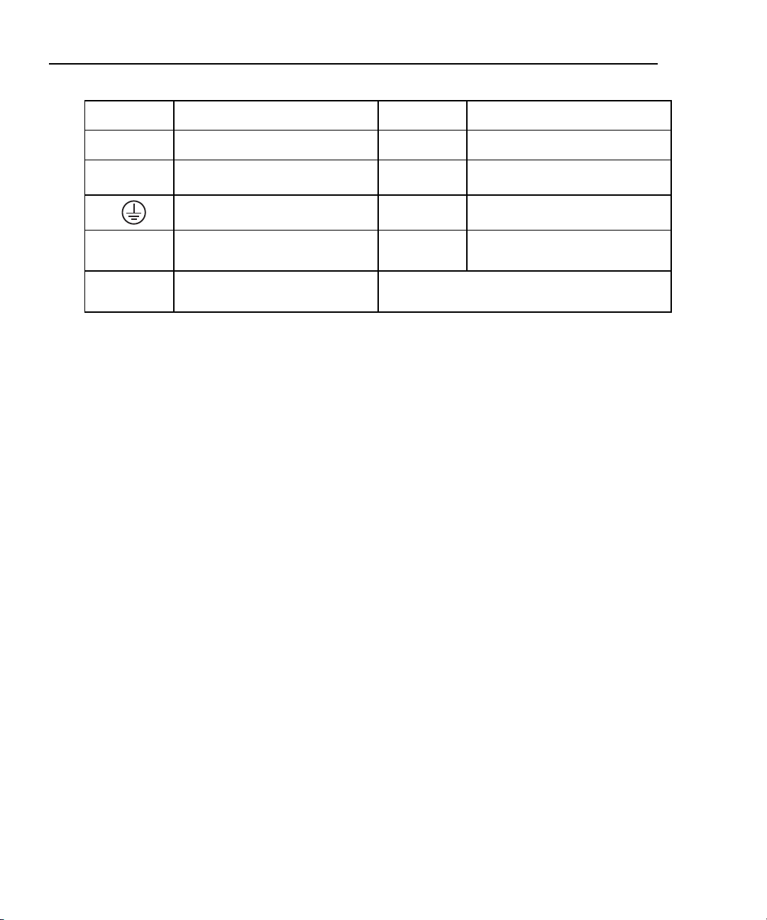
Table 1-2. Symbols Used on the Calibrator
AC (Alternating Current)
DC (Direct Current)
Pressure
Chassis protective ground
Important Information. See
manual.
Hazardous voltage. Risk of
electric shock
Earth ground
Resistance
Conforms to European Union
directives
Canadian Standards Association,
NRTL
International ON/OFF symbol.
1-4
Page 15
Getting Started
Getting Acquainted with the Calibrator
Getting Acquainted with the Calibrator
Input and Output Terminals
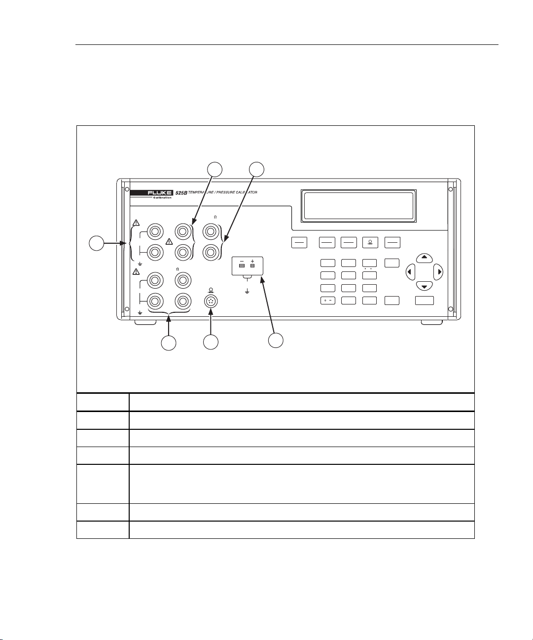
Figure 1-1 shows the Calibrator input and output terminals and explains their use.
1
2
VOLTS
100mA MAX
OUTPUT
1
100V MAX
20V PK
MAX
INPUT
20V PK
MAX
HI
LO
4W RTD
HI
LO
6
mA
RTD
HI
LO
SENSE
5
TC
INPUT/OUTPUT
20V PK
MAX
3
ZERO
9
C / F
6
AUTOSET
3
•
TYPE
UNITS
SHIFT
ENTER
CE
STBY
OPR
VOLTS
TC
mA
RTD
OUTPUT
INPUT
8
7
CJC SETUP
5
4
SET RECALL
2
1
LOCAL EXP
RNG LOCK
/
0
4
fcn08f.eps
No Description
Terminals used to output DC Volts.
Terminals used to output DC current.
Terminals used to simulate RTDs and resistance.
Terminal for thermocouple input and simulation. The terminal accepts a miniature
polarized thermocouple plug with flat, in-line blades spaced 7.9 mm (0.312 in) center
to center.
Pressure module input.
Input terminals used to measure 4-wire RTD and resistance.
Figure 1-1. Input and Output Terminals and Connectors
1-5
Page 16
525B
Users Manual
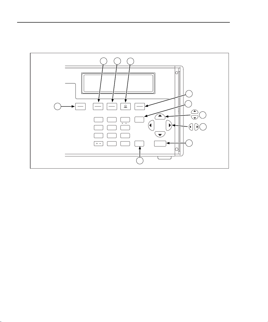
Using the Keys
Figure 1-2 shows the Calibrator pushbuttons and Table 1-3 explains their use.
Other function keys are shown in Figure 1-3 and described in Table 1-4.
32
4
5
6
7
8
9
ZERO
C / F
TYPE
UNITS
SHIFT
9
6
3
ENTER
•
CE
1
STBY
OPR
VOLTS
OUTPUT
RNG LOCK
TC
mA
RTD
INPUT
8
7
CJCSETUP
5
4
SET RECALL
2
1
LOCAL EX P
/
0
AUTOSET
10
fcn09f.eps
Figure 1-2. Pushbuttons
1-6
Page 17

Getting Started
Getting Acquainted with the Calibrator
Table 1-3. Pushbutton Usage
No Name Description
1
Cycles the Calibrator through Standby and Operate
modes.
Toggles between DC voltage and DC current modes.
Toggles between the current thermocouple and current
RTD.
Selects the pressure measurement mode.
Selects a thermocouple or RTD type. For pressure
measurement, this is used to select the pressure
conversion units.
Selects the alternate function above the numeric keys.
• Increases or decreases the output level.
• Also used to adjust LCD contrast and brightness and
to select options on the Interface and Address
menus.
Selects a different digit to change.
CE (Clear Entry) clears a partially completed keypad entry
from the display. The display reverts to the last known
good entry.
Loads a newly entered output value into the Calibrator.
The new value is an entry from the numeric keypad. Also
used when entering custom RTD coefficients and when
you adjust the display or contrast.
1-7
Page 18
525B
Users Manual
STBY
OPR
6
VOLTS
mA
5
OUTPUT
7
4
4
3
SET RECALL
1
2
RNG LOCK
/
TC
RTD
INPUT
ZERO
8
CJCSETUP
C / F
5
AUTOSET
2
LOCAL EXP
0
7
TYPE
UNITS
9
6
3
•
SHIFT
8
9
ENTER
1
10
12
11
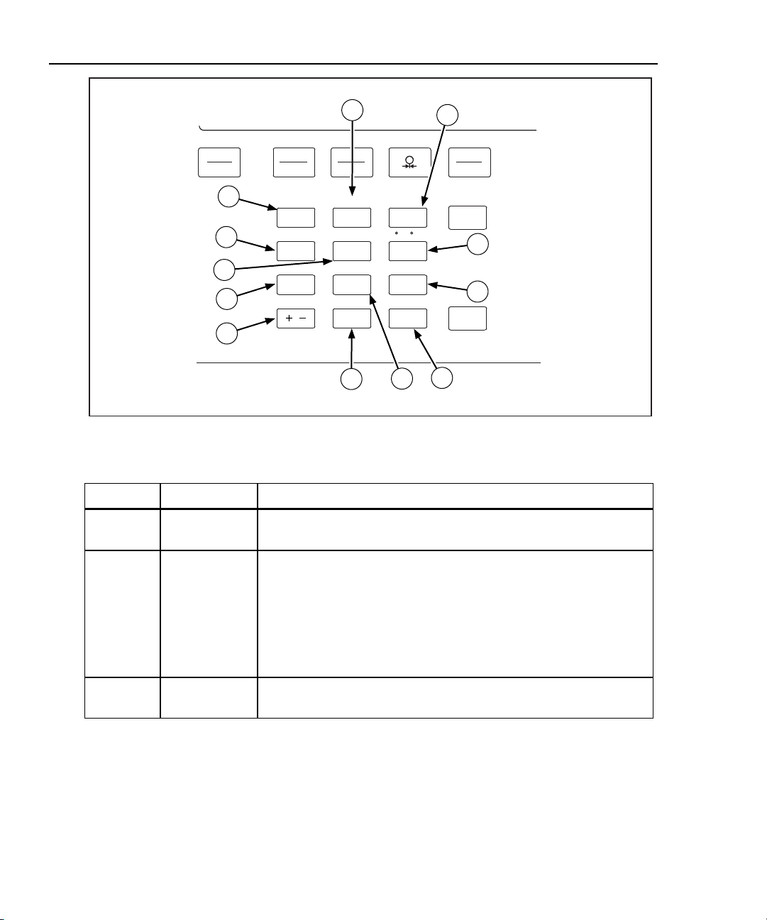
Figure 1-3. Calibrator Function Keys
Table 1-4. Function Keys
No Name Description
RNG LOCK
SET
Activates/deactivates the autorange feature of the Calibrator in
Voltage source modes.
Used to program a setpoint step for any output mode.
Key in the desired output and press . SETPOINT # appears
on the display. Select a setpoint number from 1 to 9. The output you
entered can now be recalled or used in the AUTOSET key
described later in this manual.
Each TC type, each RTD/OHMS type, mA, and Volts each have 9
programmable setpoints.
CJC
Toggles between the internal and external cold junction reference
locations.
fcn11f.eps
1-8
Page 19

Getting Started
Getting Acquainted with the Calibrator
Table 1-4. Function Keys (cont)
No Name Description
SETUP
OUTPUT
INPUT
ZERO
°C/°F
AUTOSET
Press to advance through the LCD Backlight, Interface, and
Address menus.
• Use and to adjust LCD backlight when the LCD menu is
displayed.
• Use and to toggle between Serial and GPIB interface when
the Interface menu is displayed.
• Use and to scroll from Address:1 to Address 30 when the
address menu is displayed.
Selects Output mode.
Selects Input mode.
Zeros the pressure module reading when in Pressure Measurement
mode.
Zeros the thermocouple TC mV/°C offset when in TC Measurement
mode.
Toggles between Centigrade and Fahrenheit when you are using
the TC or RTD functions.
AUTOSET runs through the setpoints you entered using the SET
function. Press . AUTO SET POINT? appears on the
display.
Enter a number between 1 and 9 that corresponds to the number of
setpoints being used. DWELL TIME 5-500? appears on the display.
Dwell time is the number of seconds between each setpoint. The
output cycles through each setpoint and then reverses the order.
For example, if 5 is entered for the number of setpoints, the
Calibrator cycles through setpoints 1, 2, 3, 4, 5 and then reverses to
setpoints 4, 3, 2, and 1.
1
Caution
Setpoints of 30 V or greater will not go to standby
when you use this feature.
EXP
Enters an exponent when you define a custom RTD.
1-9
Page 20

525B
Users Manual
No Name Description
Display Error Messages
Table 1-5 lists informative messages that may appear on the front panel display.
An explanation of each message is also provided.
RECALL
LOCAL
Table 1-4. Function Keys (cont)
Used to recall a programmed set point.
Press . RECALL SPT # appears on the display. Enter the
number of the output setpoint that you want to use. The output will
then be programmed to the setpoint you entered.
Used to regain local control of the Calibrator. If you set the
Calibrator to a remote state using the remote commands, all the
front panel keys are locked out except the Local key. When you
press the Local key, the front panel is unlocked.
Note
This function does not work when you set the Calibrator using the
Remote with Lockout command. In Remote with Lockout mode,
ALL keys are locked out and the Local key will not unlock the
front panel
.
Table 1-5. Display Error Messages
Message Explanation
OVER RANGE May be displayed in all output modes if you enter a value from the
front panel keypad that exceeds the output range of the function.
OVER LOAD May be displayed in V and mA output modes when the current is
exceeded for volts and the resistance is exceeded for mA.
OL Displayed in Input modes when the measured value exceeds the
upper limit of the range.
This error may also display in Output mode when the range is
locked and an automatically recalled set point exceeds the locked
range. For example, set point 1 (SP1) is set to 1V, SP2 is set to 2V,
and SP3 is set to 100V, the range is locked to 10V range and the
Calibrator is set up to automatically output the first 3 setpoints.
When the Calibrator reaches SP3, the display reads OL, and the
output is set to 0 for the duration of that setpoint.
-OL Displayed in Input modes when the measured value exceeds the
lower limit of the range.
INITIALIZATION FAILURE Displayed when the Calibrator fails to power up properly.
1-10
Page 21
Getting Started
Getting Acquainted with the Calibrator
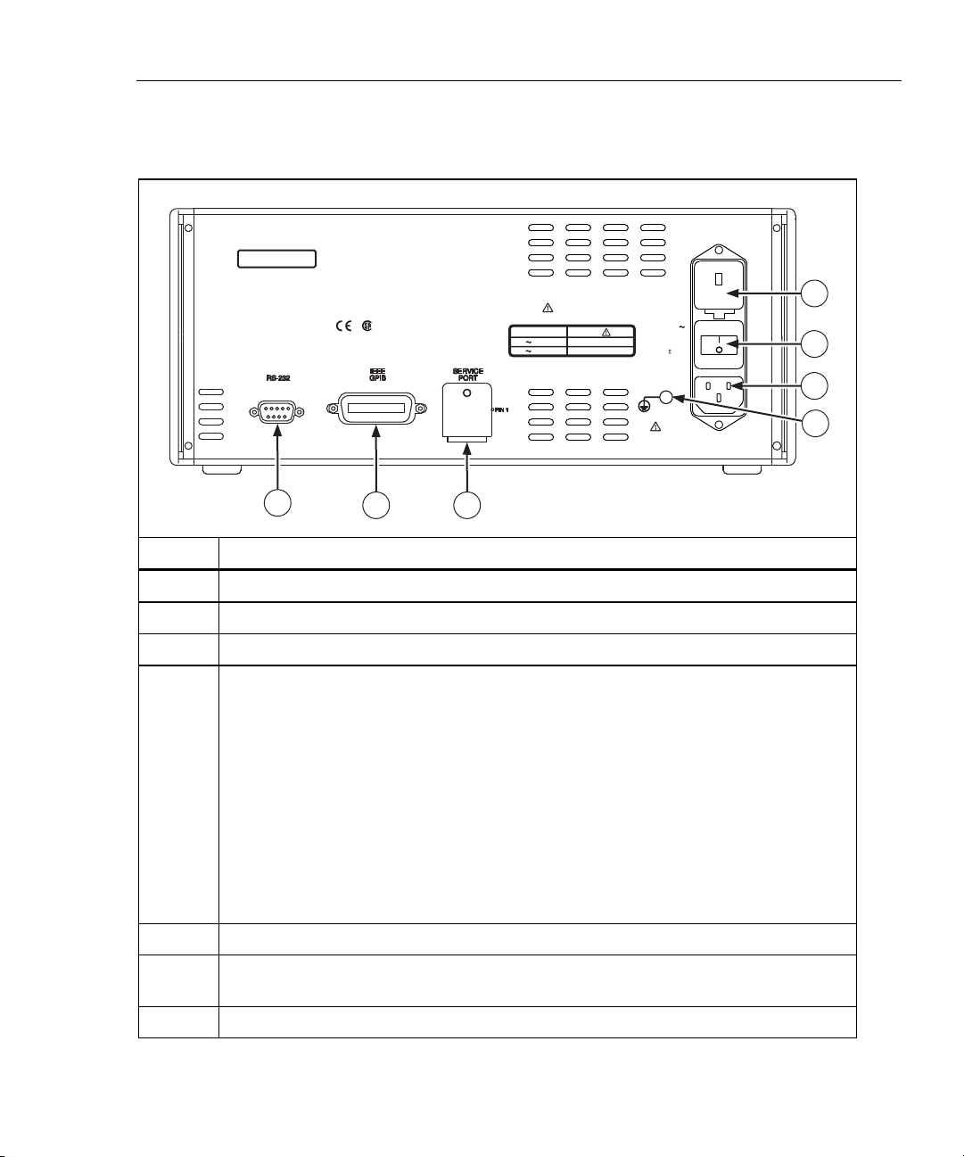
Rear Panel View
Figure 1-4 shows the features on the rear panel of the Calibrator and explains their
use.
NO INTERNAL USER SERVICEABLE PARTS
REFER SERVICE TO QUALIFIED
SERVICE PERSONNEL
FLUKE CORPORATION
MADE IN USA
PATENTS PENDING
www.fluke.com
C US
WARNING: FOR FIRE PROTECTION
REPLACE ONLY
WITH A 250V FUSE
OF INDICATED RATING?
MAINS SUPPLY
:
198V - 264V
5x20mm0.25A 250V
5x20mm0.125A 250V
120V: 90V - 132V
240V
FUSE
47Hz - 63Hz
15VA MAX
300V
CAT
CHASSIS
GROUND
1
2
3
1
WARNING: TO AVOID ELECTRIC SHOCK
GROUNDING CONNECTOR IN POWER CORD
MUST BE CONNECTED
7
56
4
fcn10f.eps
No Description
Power line fuse compartment. Contains fuses and line voltage selector.
The power switch turns the power on and off.
A grounded three-prong AC connector that accepts the line power cord.
The Chassis Ground terminal is internally connected to the ground prong of the AC
connector.
Warning
To avoid shock hazard, connect the factory supplied threeconductor power cord to a properly grounded power outlet. Do not
use a two-conductor adapter or extension cord; this will break the
protective ground connection.
Use the rear panel CHASSIS GROUND terminal as a connection
point for a protective grounding wire if there is any question about
the effectiveness of instrument earth grounding through the line
power cord ground wire.
Service port used to download new firmware to the Calibrator.
The IEEE-488 connector is a standard parallel interface for operating the 525B in
remote control as a talker/listener on the IEEE-488 bus.
The RS-232 connector is used for serial remote control of the 525B.
Figure 1-4. Rear Panel View
1-11
Page 22

525B
Users Manual
1-12
Page 23

Using Output Mode
In Output mode, the Calibrator generates calibrated signals for testing and
calibrating process instruments. In Output mode, the Calibrator:
• supplies voltage, current, and resistance
• simulates the output of RTD and TC temperature sensors
The
OVER RANGE message displays if you enter an invalid output
using the keypad. If you enter an out-of-range value, the Calibrator
reverts to the last known good value. You do not need to press .
When adjusting an output using the keys, the Calibrator will
not display or let you enter an out-of-range value.
Chapter 2
Using Output Mode
Note
Note
The figures is this chapter show how to connect to a Fluke 725
Multifunction Process Calibrator. For other instruments, refer to the
users manual for connection instructions.
2-1
Page 24
525B
Users Manual
Simulating Thermocouple Temperature
Connect the Calibrator TC input/output to the unit under test (UUT) with
thermocouple wire and the appropriate thermocouple mini-connector. Supported
TC types are listed in Chapter 7. Figure 2-1 shows this connection.
To simulate temperature using a thermocouple (TC):
1. Attach the thermocouple extension wire as shown in Figure 2-1. One pin is
wider than the other. Do not try to force a miniplug in the wrong polarization.
2. Press until TC is selected.
3. If necessary, press for TC OUT mode.
4. Press to select the desired thermocouple type.
5. Use the numeric keypad to enter the desired output value and press . You
can also adjust the output value by pressing . Press to select a
different digit to modify.
HI
LO
HI
LO
mA
100mA MAX
SENSE
RTD
HI
LO
TC
INPUT/OUTPUT
TC
20V PK
MAX
STBY
OPR
VOLTS
mA
OUTPUT
INPUT
7
4
SET RECALL
1
LOCAL EXP
RNG LOCK
/
TC
RTD
8
CJC SETUP
5
2
0
TYPE
UNITS
ZERO
C / F
AUTOSET
SHIFT
9
6
3
ENTER
•
OUTPUT
100V MAX
20V PK
MAX
INPUT
20V PK
MAX
VOLTS
4W RTD
Figure 2-1. Connection to Simulate Thermocouple Temperature
CE
fcn07f.eps
2-2
Page 25
Using Output Mode
Using Output Mode
Simulating Temperature Using Resistance Temperature Detectors (RTDs)
RTDs have a characteristic resistance at specific temperatures. The simulated
output, then, is a resistance value based on the selected temperature and type of
RTD being simulated.
To simulate temperature using a resistance temperature detector:
1. Connect the Calibrator to the unit under test (UUT) as shown in Figure 2-2.
2. Press until RTD is selected.
3. If necessary, press for RTD OUT mode.
4. Press to select the desired RTD type.
5. Use the numeric keypad to enter the desired output value and press . You
can also adjust the output value by pressing . Press to select a
different digit to modify.
6. Press to activate output.
2
725
MULTIFUNCTION CALIBRATOR
RTD
mA
100mA MAX
HI
HI
LO
LO
HI
SENSE
LO
TC
INPUT/OUTPUT
20V PK
MAX
STBY
OPR
VOLTS
TC
mA
RTD
OUTPUT
INPUT
7
CJC SETUP
4
SET RECALL
1
LOCAL EXP
RNG LOCK
/
8
5
2
0
TYPE
UNITS
ZERO
C / F
AUTOSET
SHIFT
9
6
3
ENTER
•
CE
fcn01f.eps
SOURCE
STORE
SETUP
RECALL
MEAS
V mA
LOOP
V mA
TC RTD
ZERO
Hz
C °F
°
100%
25%
25%
0%
OUTPUT
100V MAX
20V PK
MAX
INPUT
20V PK
MAX
VOLTS
4W RTD
Figure 2-2. Connection to Simulate a RTD Temperature
2-3
Page 26

525B
Users Manual
Simulating Custom RTD Coefficients
The USR_DEF RTD type allows the Calibrator to simulate a custom curve-fit
RTD.
To enter the coefficients for a custom RTD:
1. Press to select RTD mode.
2. Press until you get the
3. Press to enter custom RTD information.
USR_DEF display.
RTD CUSTOM (1-5) appears on
the Calibrator display. You can store up to five custom RTD definitions on the
Calibrator.
4. Press a number key to specify the RTD you want to define (1-5). You can
press to step through definitions without changing the values.
5. When the
SET/RECALL display appears, press to define a custom RTD
coefficient.
6. Enter the
7. Enter the
8. Enter the nominal resistance (R
MIN TEMP and press .
MAX TEMP and press .
) and press .
0
9. Enter the temperature coefficients and press . Press to enter a
positive or negative exponent for the coefficient.
To use a custom RTD:
1. Press to enter RTD mode.
2. Press until you get the
3. Press to use custom RTD information.
USR_DEF display.
RTD CUSTOM (1-5) appears on the
Calibrator display. You can store up to five custom RTD definitions on the
Calibrator.
2-4
4. Press a number key to select the RTD you want to use (1-5).
5. When the
SET/RECALL display appears, press to recall and use the
selected RTD.
Page 27
Using Output Mode
Using Output Mode
Default RTD Coefficients
The USR_DEF function of the calibrator uses the Calendar-Van Dusen equation
for outputting and measuring custom RTDs. The C coefficient is only used for the
subrange –260 to 0 degrees Celsius. Only the A and B coefficients are needed for
the subrange 0 to 630 degrees. The R0 is the resistance of the probe at 0 degrees
Celsius. All of the USR_DEF will be set to PT385 as shown in Table 2-1.
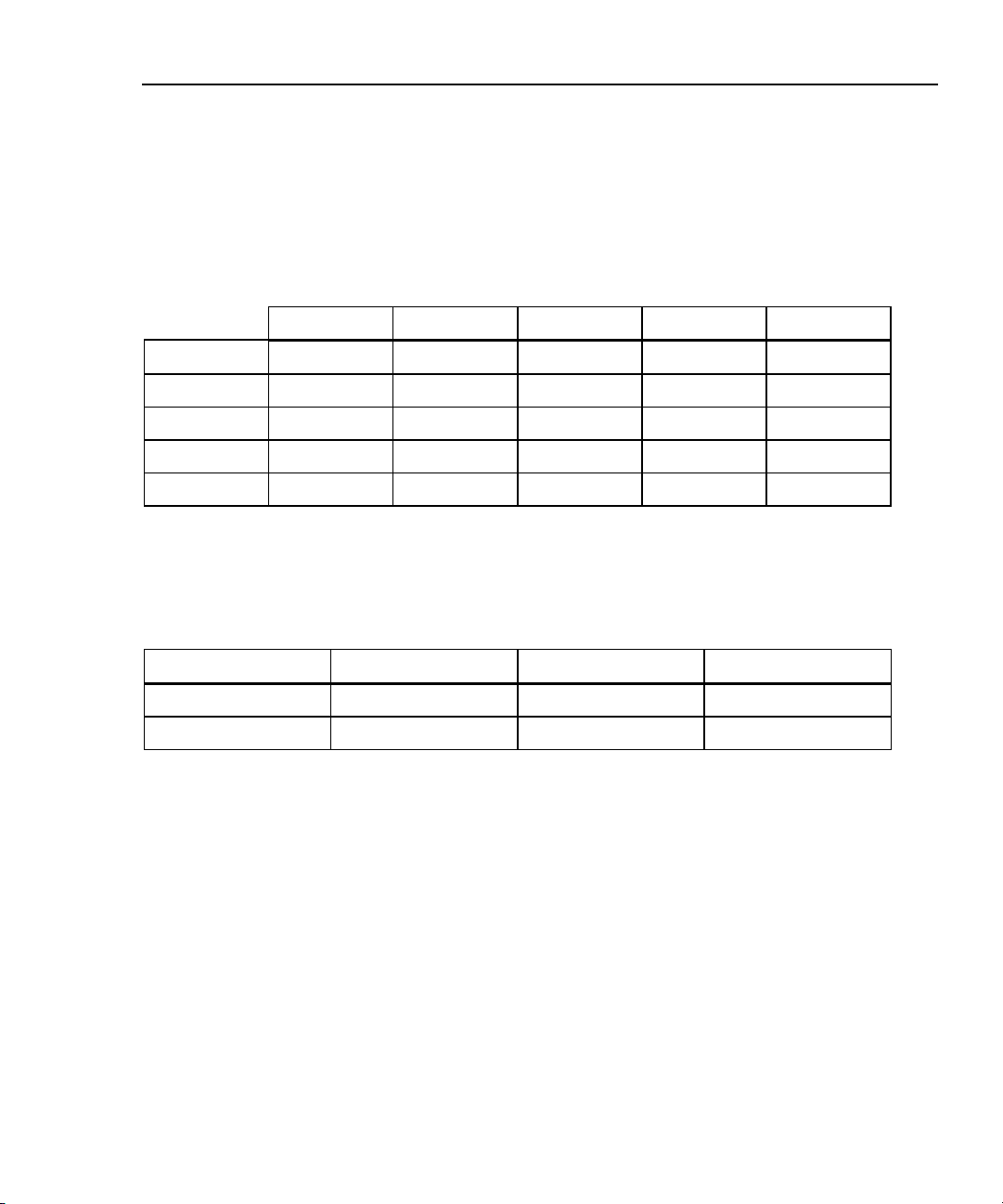
Table 2-1. Default RTD Coefficients
Sub range R0 Coefficient A Coefficient B Coefficient C
USR_DEF1 0 to 630 100 3.908X10⁻³ -5.775e-7
USR_DEF2 -260 to 0 100 3.908X10⁻³ -5.775e-7 -4.183e-12
USR_DEF3 0 to 630 100 3.908X10⁻³ -5.775e-7
USR_DEF4 -260 to 0 100 3.908X10⁻³ -5.775e-7 -4.183e-12
USR_DEF5 0 to 630 100 3.908X10⁻³ -5.775e-7
If other types of RTDs are required, Table 2-2 shows the coefficients for types
PT391 and PT392. The C coefficient is only used for temperatures below 0
degrees Celsius.
2
Table 2-2. Other Commonly Used RTDs
RTD Type Coefficient A Coefficient B Coefficient C
PT392 3.9848X10⁻³ -5.87X10⁻⁷ -4X10-12
PT391 3.9692X10⁻³ -5.8495X10⁻⁷ -4.2325X10⁻¹²
The SPRT function of the calibrator uses ITS-90 standard coefficients for
measuring a SPRT. Since the five coefficients are deviations all of them will be set
to 0.
The coefficients A- and B- represent the A4 and B4 coefficient, obtained when the
SPRT is calibrated at the triple points of argon, mercury and water. This covers the
83.8058K to 273.16K subrange. Coefficients A, B and C can represent different
coefficients based on which subranges of the SPRT has been calibrated. For
example, if the 273.15K to 933.473K subrange was used, A, B and C would
represent A7, B7 and C7 whereas if the 273.15K to 692.67K subrange was used, A
and B would represent A8 and B8 and C=0.
2-5
Page 28

525B
Users Manual
Entering Custom Standard Platinum Resistance Thermometer (SPRT) Coefficients
To enter coefficients for a custom SPRT:
1. Press to enter RTD mode.
2. Press until you get the
3. Enter the
4. Enter the
MIN TEMP and press .
MAX TEMP and press .
5. Enter the nominal resistance (R
RTD SPRT display and press .
) and press .
0
6. Enter the temperature coefficients and press . Press to enter a
positive or negative exponent for the coefficient.
2-6
Page 29
Using Output Mode
Using Output Mode
Output DC Voltage
The Calibrator is a fully programmable precision source of DC voltage from 0 V
to 100 V. The Calibrator can only output positive (+) values.
To output DC voltage:
1. Connect the Calibrator to the UUT as shown in Figure 2-3.
2. Press for V out display.
3. Use the numeric keypad to enter the desired output value and press . You
can also adjust the output value by pressing . Press to select a
different digit to modify.
4. Press to activate output.
Note
For safety purposes, the Calibrator resets to standby when output is
set to 30 V or greater.
2
725
MULTIFUNCTION CALIBRATOR
RTD
mA
100mA MAX
HI
HI
LO
LO
HI
SENSE
LO
TC
INPUT/OUTPUT
20V PK
MAX
STBY
OPR
VOLTS
TC
mA
RTD
OUTPUT
INPUT
7
CJC SETUP
4
SET RECALL
1
LOCAL EXP
RNG LOCK
/
8
5
2
0
TYPE
UNITS
ZERO
C / F
AUTOSET
SHIFT
9
6
3
ENTER
•
CE
fcn02f.eps
MEAS
SOURCE
STORE
SETUP
RECALL
V mA
LOOP
V mA
TC RTD
ZERO
Hz
C °F
°
100%
25%
25%
0%
OUTPUT
100V MAX
20V PK
MAX
INPUT
20V PK
MAX
VOLTS
4W RTD
Figure 2-3. Connection for Setting DC Voltage Output
2-7
Page 30
525B
Users Manual
Output Resistance
To output resistance:
1. Connect the Calibrator to the UUT as shown in Figure 2-4.
2. Press until RTD mode is selected.
3. If necessary, press for RTD OUT mode.
4. Press to select the appropriate ohms output range (400 or 4000 ohms).
5. Use the numeric keypad to enter the desired output value and press . You
6. Press to activate output.
can also adjust the output value by pressing . Press to select a
different digit to modify.
Note
If the input current is excessive, the Calibrator will beep, display the
message
OVER LOAD, and enter Standby mode. You will need to
check the input current and change it accordingly. Resistance
specifications are listed in Chapter 7.
2-8
MEAS
SOURCE
STORE
SETUP
RECALL
725
V mA
LOOP
V mA
TC RTD
MULTIFUNCTION CALIBRATOR
ZERO
VOLTS
OUTPUT
Hz
C °F
°
100%
25%
25%
0%
100V MAX
20V PK
MAX
INPUT
20V PK
MAX
4W RTD
RTD
mA
100mA MAX
HI
HI
LO
LO
HI
SENSE
LO
TC
INPUT/OUTPUT
20V PK
MAX
STBY
OPR
VOLTS
mA
RTD
OUTPUT
INPUT
7
CJC SETUP
4
SET RECALL
1
LOCAL EXP
RNG LOCK
/
TC
8
5
2
0
TYPE
UNITS
ZERO
C / F
AUTOSET
SHIFT
9
6
3
ENTER
•
CE
fcn01f.eps
Figure 2-4. Connection for Setting Resistance Output
Page 31

Using Output Mode
Output Current
Output Current
The Calibrator is a fully programmable precision source of DC current from 0 mA
to 100 mA. The Calibrator can only output positive (+) values.
To output current:
1. Connect the Calibrator to the UUT as shown in Figure 2-5.
2. If necessary, press to select mA.
3. Use the numeric keypad to enter the desired output value and press . You
can also adjust the output value by pressing . Press to select a
different digit to edit.
4. Press activate output.
Note
If
OVER LOAD appears on the display you may not have a
completed circuit loop. When the circuit is complete, the message
will disappear.
2
725
MULTIFUNCTION CALIBRATOR
RTD
mA
100mA MAX
HI
HI
LO
LO
HI
SENSE
LO
TC
INPUT/OUTPUT
20V PK
MAX
STBY
OPR
VOLTS
TC
mA
RTD
OUTPUT
INPUT
7
CJC SETUP
4
SET RECALL
1
LOCAL EXP
RNG LOCK
/
8
5
2
0
ZERO
C / F
AUTOSET
TYPE
UNITS
SHIFT
9
6
3
ENTER
•
CE
fcn03f.eps
MEAS
SOURCE
STORE
SETUP
RECALL
V mA
LOOP
V mA
TC RTD
ZERO
Hz
C °F
°
100%
25%
25%
0%
OUTPUT
100V MAX
20V PK
MAX
INPUT
20V PK
MAX
VOLTS
4W RTD
Figure 2-5. Connection for Setting Current Output
2-9
Page 32

525B
Users Manual
2-10
Page 33

Using Input Mode
In Input mode, the Calibrator measures resistance, and temperature from RTD and
thermocouple sensors and displays pressure measurements from Fluke 700 and
525A-P series pressure modules.
The figures in this chapter show how to connect to a Fluke 725
Multifunction Process Calibrator. For other instruments, refer to
their users manual for connection instructions.
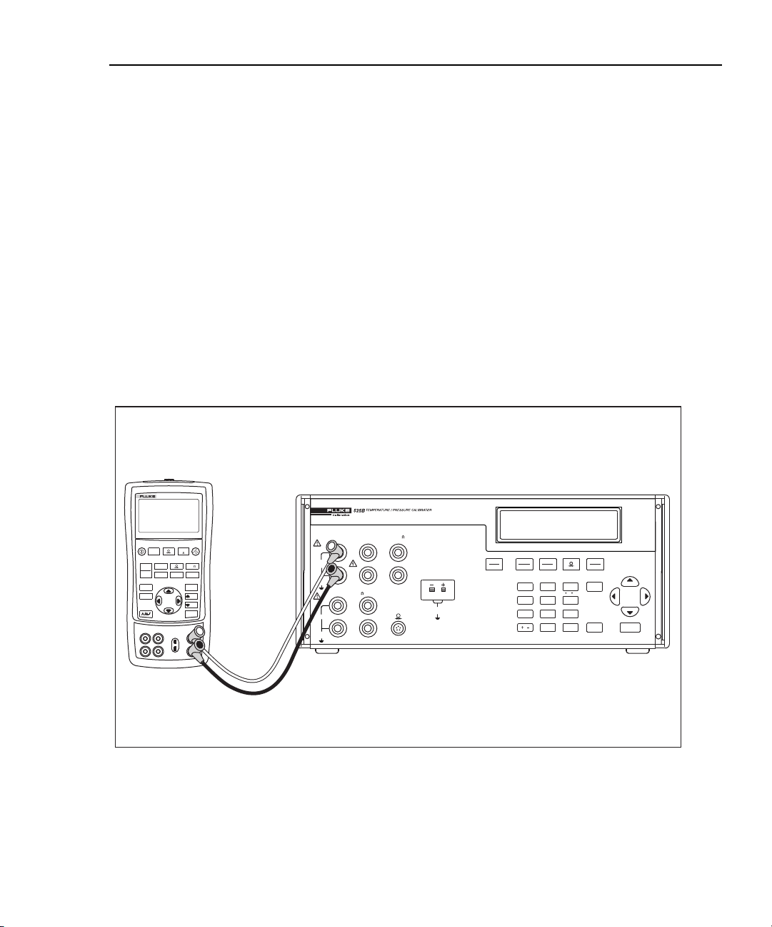
Measuring Resistance
The Calibrator will only measure resistance using a 4-wire system. The Input
terminals supply a fixed DC current and the Sense terminals measure the voltage.
When you connect to a 4-wire calibrator, connect the Input to the output terminals
and the Sense to the sense terminals for proper measurement.
Chapter 3
Using Input Mode
Note
To measure resistance using a 4-wire to 2-wire connection:
1. Connect the Calibrator to the instrument you want to test as shown in
Figure 3-1.
2. If necessary, press to select RTD mode.
3. Press to select an ohms range (400 or 4000 ohms).
4. If necessary, press for RTD IN mode.
3-1
Page 34

525B
Users Manual
725
MULTIFUNCTION CALIBRATOR
RTD
mA
100mA MAX
HI
HI
LO
LO
HI
SENSE
LO
TC
INPUT/OUTPUT
20V PK
MAX
MEAS
SOURCE
STORE
SETUP
RECALL
V mA
LOOP
V mA
TC RTD
ZERO
Hz
C °F
°
100%
25%
25%
0%
OUTPUT
100V MAX
20V PK
MAX
INPUT
20V PK
MAX
VOLTS
4W RTD
Figure 3-1. Measuring Resistance Using a 4-Wire to 2-Wire Connection
Measuring Temperature Using Thermocouples
The Calibrator supports numerous standard thermocouples. See Chapter 7 for
supported thermocouple specifications.
You can use the key to toggle the cold junction reference location (CJC)
between the internal and external cold junction reference locations. External cold
junction reference is 0 °C or 32 °F. This is used primarily when you want to use an
external cold junction for conducting temperature measurements. The
message appears on the display when the Calibrator is in external CJC mode.
STBY
OPR
VOLTS
TC
mA
RTD
OUTPUT
INPUT
7
CJC SETUP
4
SET RECALL
1
LOCAL EXP
RNG LOCK
/
TYPE
UNITS
ZERO
C / F
AUTOSET
SHIFT
9
6
3
ENTER
•
CE
fcn04f.eps
8
5
2
0
XCJC status
3-2
Page 35

Using Input Mode
Using Input Mode
To measure temperature using a thermocouple:
1. Attach the thermocouple leads to the TC input/output connector as shown in
Figure 3-2. One pin is wider than the other. Do not attempt to force the plug in
the wrong polarization.
Note
If the Calibrator and the TC plug are at different temperatures, wait
three minutes or more for the connector temperature to stabilize
after you plug the miniplug into the connector.
2. Press to select TC mode.
3. If necessary, press to place the Calibrator in TC IN mode.
4. Press to select the desired TC type. You can toggle between ºC and ºF
temperature units by pressing .
3
RTD
mA
100mA MAX
HI
HI
LO
LO
HI
SENSE
LO
TC
INPUT/OUTPUT
TC
20V PK
MAX
STBY
OPR
VOLTS
TC
mA
RTD
OUTPUT
INPUT
8
7
CJC SETUP
5
4
SET RECALL
2
1
LOCAL EXP
RNG LOCK
/
0
ZERO
9
C / F
6
AUTOSET
3
•
OUTPUT
100V MAX
20V PK
MAX
INPUT
20V PK
MAX
VOLTS
4W RTD
Figure 3-2. Measuring Temperature with a Thermocouple
TYPE
UNITS
SHIFT
ENTER
CE
fcn07f.eps
3-3
Page 36

525B
Users Manual
Thermocouple Zero Calibration
To obtain the optimum measurement accuracy, you must perform a zero
calibration when operating the Calibrator outside of the ambient temperature range
of 18 ºC to 28 ºC. The zero calibration must be performed with the Calibrator
thermally stable at the ambient temperature of operation.
To perform a thermocouple zero calibration:
1. Insert the supplied Thermocouple Shorting Jumper in the TC input/output
connector. One pin is wider than the other.
2. Allow time for the connection to become thermally stable.
3. Press to select TC mode.
4. If necessary, press to put the Calibrator in TC IN mode.
5. Press to select mV/ºC.
6. If the display does not read 0.000 mV, press to zero the Calibrator.
Offset values within the range of
measurement.
Note
±
1.000 mV can be zeroed out of the
3-4
Page 37

Using Input Mode
Using Input Mode
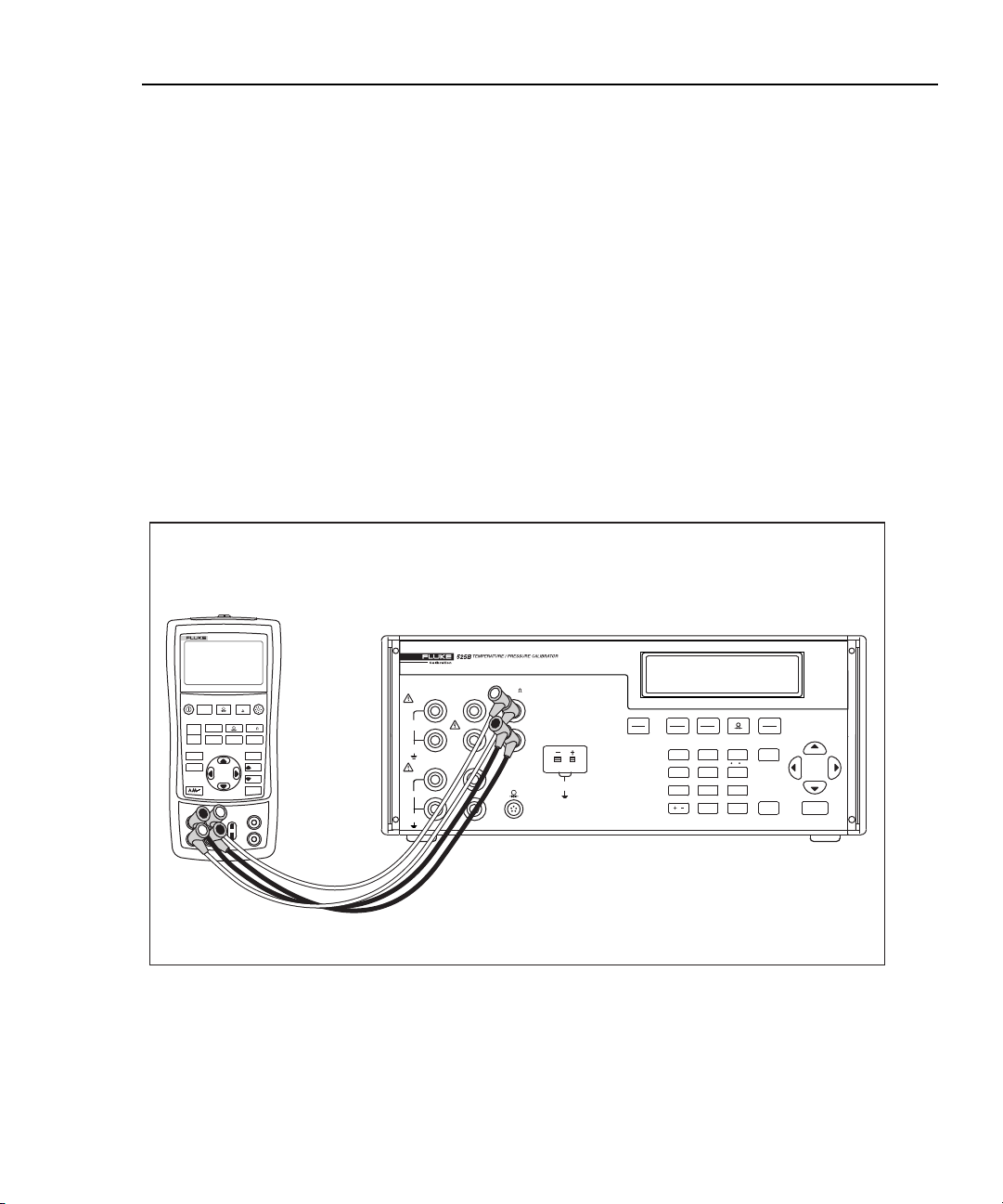
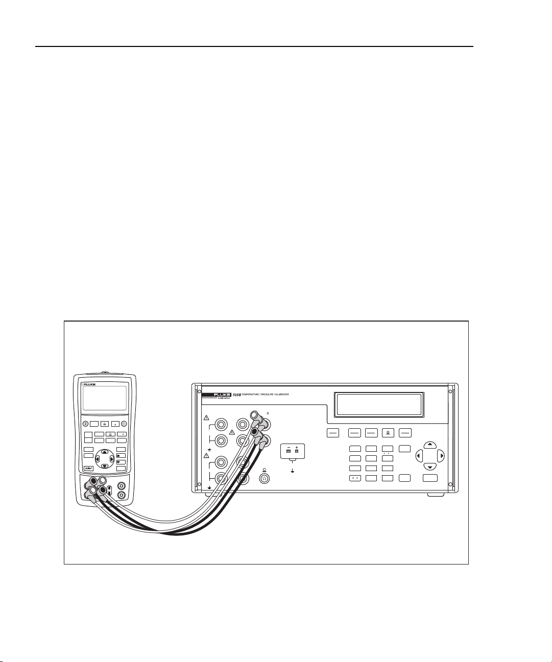
Measuring Temperature Using Resistance Temperature Detectors (RTDs)
You must use a 4-wire connection to achieve the Calibrator accuracy
specifications.
To measure the RTD output from an instrument:
1. Connect the Calibrator to the instrument you want to measure as shown in
Figure 3-3.
2. Press to select RTD mode.
3. If necessary, press to put the Calibrator in RTD IN mode.
4. Press to select the desired RTD type.
You can toggle between ºC and ºF temperature units by pressing
.
725
MULTIFUNCTION CALIBRATOR
3
RTD
mA
100mA MAX
HI
HI
LO
LO
HI
SENSE
LO
TC
INPUT/OUTPUT
20V PK
MAX
STBY
OPR
VOLTS
TC
mA
RTD
OUTPUT
INPUT
7
CJC SETUP
4
SET RECALL
1
LOCAL EXP
RNG LOCK
/
8
5
2
0
TYPE
UNITS
ZERO
C / F
AUTOSET
SHIFT
9
6
3
ENTER
•
CE
fcn06f.eps
MEAS
SOURCE
STORE
SETUP
RECALL
V mA
LOOP
V mA
TC RTD
ZERO
Hz
C °F
°
100%
25%
25%
0%
OUTPUT
100V MAX
20V PK
MAX
INPUT
20V PK
MAX
VOLTS
4W RTD
Figure 3-3. Measuring RTD Output from an Instrument
To measure temperatures using an RTD probe:
1. Connect an RTD probe to the Calibrator as shown in Figure 3-4.
2. Press to select the RTD mode.
3. If necessary, press to put the Calibrator in RTD IN mode.
3-5
Page 38

525B
Users Manual
4. Press to select the desired RTD type.
You can toggle between ºC and ºF temperature units by pressing
.
OUTPUT
100V MAX
20V PK
MAX
INPUT
20V PK
MAX
VOLTS
HI
LO
4W RTD
HI
LO
mA
100mA MAX
HI
LO
SENSE
RTD
TC
INPUT/OUTPUT
20V PK
MAX
STBY
OPR
VOLTS
TC
mA
RTD
OUTPUT
INPUT
8
7
CJC SETUP
5
4
SET RECALL
2
1
LOCAL EXP
RNG LOCK
/
0
ZERO
C / F
AUTOSET
Figure 3-4. Measuring Temperature using an RTD Probe
TYPE
UNITS
SHIFT
9
6
3
ENTER
•
CE
fcn05f.wmf
3-6
Page 39

Using Input Mode
Using Input Mode
Entering and Using Custom RTDs
The USR_DEF RTD type allows the Calibrator to simulate a custom curve-fit
RTD.
To enter the coefficients for custom RTDs:
1. Press to select RTD mode.
3
2. Press until you get the
3. Press to enter custom RTD information.
USR_DEF display.
RTD CUSTOM (1-5) appears on
the Calibrator display. You can store up to five custom RTD definitions on the
Calibrator.
4. Press a number key to specify the RTD you want to define (1-5).
5. When the
SET/RECALL display appears, press to define a custom RTD
coefficient.
6. Enter the
7. Enter the
8. Enter the nominal resistance (R
MIN TEMP and press .
MAX TEMP and press .
) and press .
0
9. Enter the temperature coefficients and press . Press to enter a
positive or negative exponent for the coefficient.
To use a custom RTD:
1. Press to enter RTD mode.
2. Press until you get the
3. Press to use custom RTD information.
USR_DEF display.
RTD CUSTOM (1-5) appears on the
Calibrator display. You can store up to five custom RTD definitions on the
Calibrator.
4. Press a number key to select the RTD you want to use (1-5).
5. When the
SET/RECALL display appears, press to recall and use the
selected custom RTD.
3-7
Page 40

525B
Users Manual
Default RTD Coefficients
The USR_DEF function of the calibrator uses the Calendar-Van Dusen equation
for outputting and measuring custom RTDs. The C coefficient is only used for the
subrange –260 to 0 degrees Celsius. Only the A and B coefficients are needed for
the subrange 0 to 630 degrees. The R0 is the resistance of the probe at 0 degrees
Celsius. All of the USR_DEF will be set to PT385 as shown in Table 3-1.
Table 3-1. Default RTD Coefficients
Sub range R0 Coefficient A Coefficient B Coefficient C
USR_DEF1 0 to 630 100 3.908X10⁻³ -5.775e-7
USR_DEF2 -260 to 0 100 3.908X10⁻³ -5.775e-7 -4.183e-12
USR_DEF3 0 to 630 100 3.908X10⁻³ -5.775e-7
USR_DEF4 -260 to 0 100 3.908X10⁻³ -5.775e-7 -4.183e-12
USR_DEF5 0 to 630 100 3.908X10⁻³ -5.775e-7
If other types of RTD are required, Table 3-2 shows the coefficients for PT391 and
PT392. Again, C is only used for temperatures below 0 degrees Celsius.
Table 3-2. Other Commonly Used RTDs
RTD Type Coefficient A Coefficient B Coefficient C
PT392 3.9848X10⁻³ -5.87X10⁻⁷ -4X10-12
PT391 3.9692X10⁻³ -5.8495X10⁻⁷ -4.2325X10⁻¹²
The SPRT function of the calibrator uses ITS-90 standard coefficients for
measuring a SPRT. Since the five coefficients are deviations all of them will be set
to 0.
The coefficients A- and B- represent the A4 and B4 coefficient, obtained when the
SPRT is calibrated at the triple points of argon, mercury, and water. This covers
the 83.8058K to 273.16K subrange. Coefficients A, B, and C can represent
different coefficients based on which subranges of the SPRT has been calibrated.
For example, if the 273.15K to 933.473K subrange was used, A, B, and C would
represent A7, B7, and C7 whereas if the 273.15K to 692.67K subrange was used,
A and B would represent A8 and B8 and C=0.
3-8
Page 41

Using Input Mode
Using Input Mode
Entering Custom SPRT Coefficients
To enter coefficients for a custom SPRT:
1. Press to enter RTD mode.
2. If necessary, press for RTD IN mode.
3
3. Press until you get the
4. Enter the
5. Enter the
6. Enter the nominal resistance (R
7. Enter the temperature coefficients and press . Press to enter a
positive or negative exponent for the coefficient.
MIN TEMP and press .
MAX TEMP and press .
RTD IN SPRT display and press .
) and press .
0
3-9
Page 42

525B
Users Manual
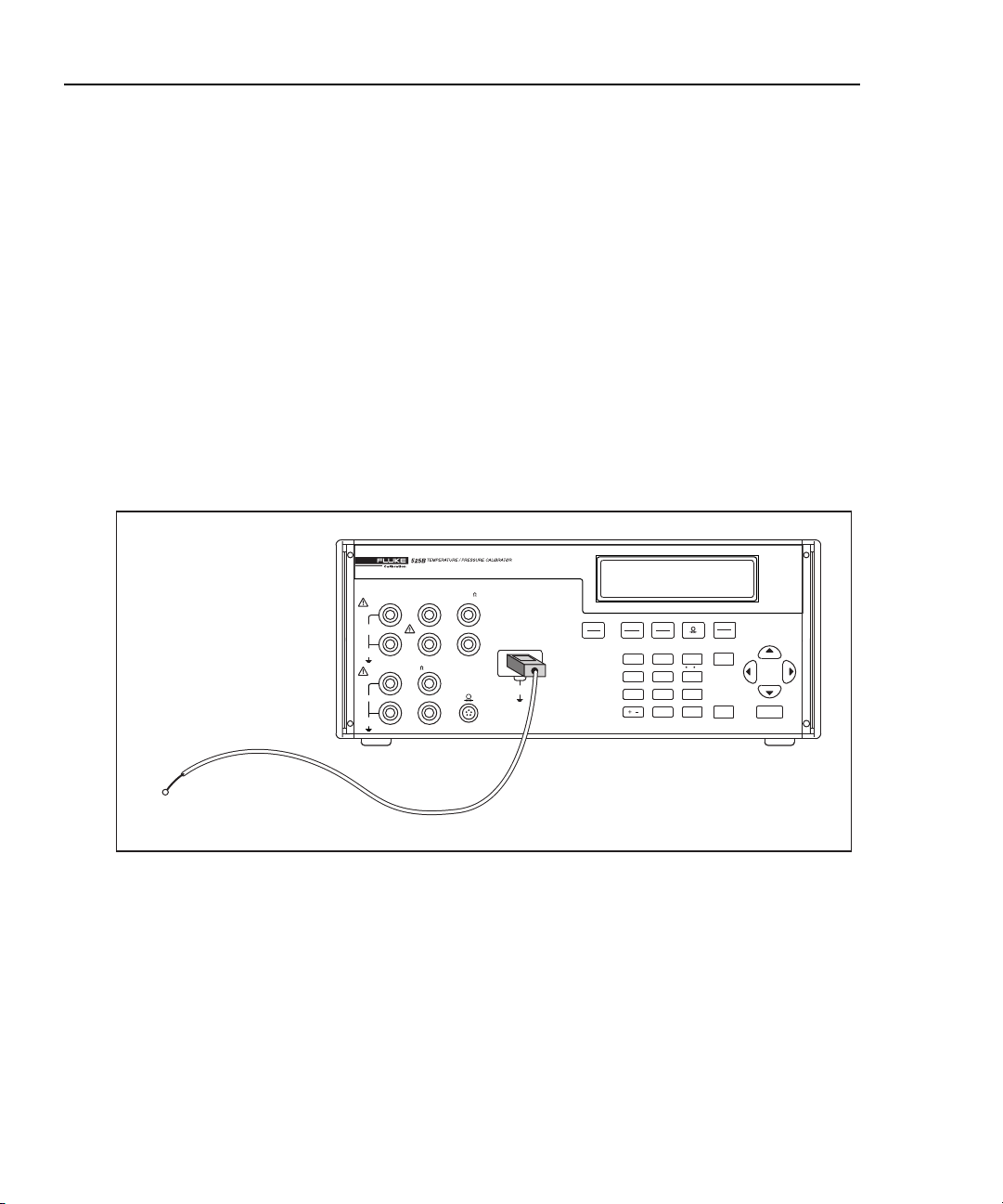
Measuring Pressure
Many ranges and types of pressure modules are available from Fluke. See
“Accessories” in Chapter 6 of this manual for a complete list of supported pressure
modules. Before you use a pressure module, read its instruction sheet. Pressure
modules vary in use, media, and accuracy.
To measure pressure, attach the appropriate pressure module for the process
pressure to be tested as shown in Figure 3-5.
To measure pressure:
1. Connect a pressure module to the Calibrator as shown in Figure 3-5.
2. Press . The Calibrator automatically senses which pressure module is
3. If appropriate, zero the pressure module as described in the module’s
4. Pressurize the module with a pressure source to the desired level.
attached and sets its range accordingly.
instruction sheet. Modules vary in zeroing procedures depending on the
module type, but all require you to press .
You can press to change pressure display units to psi, inH20 4ºC,
inH20 20ºC, cmH20 4ºC, cmH20 20º C, bar, mbar, kPa, inHg 0ºC, mmHg 0ºC,
kg/cm2.
3-10
MAX TORQUE, SEE MANUAL
700PD6
L H
PRESSURE MODULE
RANGE
-15/+100 PSIG
-1/+7 bar
BURST PRESSURE 300 PSIG
Figure 3-5. Connection for Measuring Pressure
OUTPUT
100V MAX
20V PK
MAX
INPUT
20V PK
MAX
VOLTS
HI
LO
4W RTD
HI
LO
mA
100mA MAX
HI
LO
SENSE
RTD
TC
INPUT/OUTPUT
20V PK
MAX
fcn21f.eps
Page 43

Introduction
This chapter describes methods for operating the Calibrator by remote control.
Remote control can be interactive, with the user controlling each step from a
terminal, or under the control of a computer program running the Calibrator in an
automated system. The Calibrator rear panel has two ports for remote operations:
• RS-232 serial port
• IEEE-488 parallel port (General Purpose Interface Bus or GPIB port)
RS-232 The serial port connects the PC and Calibrator. You can write your own
computer programs using the command set, or operate the PC as a terminal and
enter individual commands, or you can purchase optional Fluke MET/CAL
software for RS-232 system operations. Typical RS-232 remote configurations are
shown in Figure 4-2.
Chapter 4
Remote Operation
IEEE-488 The IEEE-488 parallel port is usually used in larger control and
calibration systems. An IEEE-488 system has the ability to serve multiple
Calibrators and multiple UUTs. Also, parallel system throughput is faster than
serial system throughput. The controller in an IEEE-488 system is typically a
Windows
488 ports. You can write your own computer programs for system operation using
the command set, or you can purchase optional Fluke calibration software
MET/CAL. Typical IEEE-488 configurations are shown in Figure 4-3. The
configuration showing the PC with two IEEE-488 ports is used with MET/CAL,
which prefers UUTs on a separate IEEE-488 port. You can also “piggy-back” the
connectors on a single IEEE-488 port.
After configuring the IEEE-488 or RS-232 port for remote operation, you are
ready to begin using the command set. The operation of the command set is
described under “Using Commands” in this chapter. A summary of remote
commands is in Chapter 5, “Remote Commands.”
4-1
®
compatible personal computer (PC) equipped with one or more IEEE-
Page 44

525B
Users Manual
Setting up the RS-232 Port for Remote Control
The Calibrator is fully programmable over an RS-232 link with a PC. You can
enter individual commands from a terminal, write your own programs using, for
example, a Windows
®
Windows
-based Fluke software such as MET/CAL.
The RS-232 cable length for the port should not exceed 15 meters (50 feet),
although longer cable lengths are permitted if the load capacitance measured at a
connection point (including signal terminator) does not exceed 2500 pF.
RS-232 Port Setup Procedure
Serial parameters are fixed with the values shown below:
• 9600 baud
• 8 data bits
• 1 stop bit
• no parity
• Xon/Xoff
• EOL (end-of-line) character CR (Carriage Return)
®
-based language such as Visual Basic, or run optional
Testing the RS-232 Port
Use the following procedure to test the Calibrator RS-232 Port connected to a PC
COM port. A typical connection is shown in Figure 4-1. Note the use of a null
modem cable for connection.
Controller
4-2
Null Modem Cable
COM Port
Figure 4-1. Testing the RS-232 Port
525B Calibrator
UUT
SERIAL
Port
fcn14f.eps
Page 45

Remote Operation
Setting up the RS-232 Port for Remote Control
4
Complete the following procedure to test RS-232 port operation using the
Windows
To test port operation:
1. Select Start->Programs->Accessories->Hyperterminal->Hyper Terminal.
2. Enter 525B for Name:, and select OK.
3. Select PC serial port which 525B is connected to (from drop-down list), for
4. Select the following setting and then select OK:
5. Select File->Properties->Settings->ASCII Setup.
6. Select the following settings and then select OK:
®
HyperTerminal application (or equivalent).
Connect using: and select OK
Bits per second: 9600
Data bits: 8
Parity: None
Stop bits: 1
Flow control: Xon / Xoff
Echo typed characters locally
Append line feeds to incoming line ends
7. Select OK.
8. Enter *IDN? and press Enter.
9. Verify that that the returned string is Fluke,525B,0,<firmware revision>.
4-3
Page 46

525B
Users Manual
RS-232
Port
COM Port
Controller
System for a UUT without a remote port.
COM PortCOM Port
SERIAL
FROM HOST
Port
525B Calibrator
UUT
SERIAL
FROM HOST
Port
4-4
UUT
525B Calibrator
Controller
System for a UUT with an RS-232 port (via PC).
Figure 4-2. Typical RS-232 Remote Control Connections
fcn15f.eps
Page 47

Remote Operation
RS-232 Interface Overview
RS-232 Interface Overview
The Calibrator RS-232 port is designed in accordance with EIA (Electronic
Industries Association) standard RS-232-C. RS-232 is a serial binary data
interchange operating at 9600 baud and distances up to 50 feet. The Calibrator rear
panel serial port is configured as DTE (Data Terminal Equipment). For detailed
information, see the EIA standard RS-232-C.
A summary of RS-232 terms, interface lines and mnemonics are shown in
Table 4-1.
Table 4-1. RS-232 Interface Wiring
Mnemonic Description
DB-9 Type DB connector, 9 pins
DTE Data Terminal Equipment
GND Ground
RX Receive Line
TX Transmit Line
4
Setting up the IEEE-488 Port for Remote Control
The Calibrator is fully programmable for use on the IEEE Standard 488 interface
bus. The IEEE-488 interface is also designed in compliance with supplemental
standard IEEE-488.2, which describes additional IEEE-488 features. Devices
connected to the IEEE-488 bus are designated as talkers, listeners, talker/listeners,
or controllers. Under remote control of an instrument, the Calibrator operates as a
talker/listener. Figure 4-3 shows typical IEEE-488 remote control connections.
A PC equipped with an IEEE-488 interface controls the Calibrator. Compatible
software for IEEE-488 operation, MET/CAL, may be purchased from Fluke.
When using the IEEE-488 remote control interface, there are two restrictions:
1. Number of Devices A maximum of 15 devices can be connected in a single
IEEE-488 bus system. For example, one instrument controller, one Calibrator,
and thirteen units under test (UUTs).
2. Cable Length The total length of IEEE-488 cables used in one IEEE-488
system is 2 meters times the number of devices in the system, or 20 meters,
whichever is less. For example, if 8 devices are connected, the maximum cable
length is 2 x 8 = 16 meters. If 15 devices are connected, the maximum cable
length is 20 meters.
4-5
Page 48

525B
Users Manual
UUT
IEEE-488 Port
Controller
System for a UUT without a remote port.
Controller
IEEE-488 Port
525B Calibrator
UUT
525B Calibrator
4-6
RS-232
Port
System for a UUT with an IEEE-488 remote port.
COM Port
UUT
Controller
System for a UUT with an RS-232 remote port.
Figure 4-3. Typical IEEE-488 Remote Control Connections
525B Calibrator
fcn13f.eps
Page 49

Remote Operation
Setting up the IEEE-488 Port for Remote Control
IEEE-488 Port Setup Procedure
Complete the following procedure to set up the Calibrator for remote operations
using the IEEE-488 remote control port. The purpose is to select GPIB as the
interface and to select the GPIB address for the interface. See Figure 4-4 for
typical connections.
To set up the IEEE-488 port:
1. Turn the Calibrator power on and wait until the initialization procedure
completes. You may operate the Calibrator during warm-up, but specifications
are not guaranteed until warm-up is complete.
2. Press SETUP ( + ).
3. Press until Remote Interface: is displayed.
4. Press the or key to select GPIB, if not already selected.
5. Press until Address: is displayed.
6. Press the or key to select the desired address. The factory default is 4.
7. Press to exit the Setup menu.
4
Testing the IEEE-488 Port
Port
Controller
Figure 4-4. Testing the IEEE-488 Port
It is beyond the scope of this manual to describe how to test the 525B IEEE-488
interface in general because Windows is not provided by default with an
application to exercise a device attached to an IEEE-488 interface card. However
if MET/CAL has been purchased, the following steps may be performed to verify
that the 525B IEEE-488 interface is functioning properly.
IEEE-488 Cable
IEEE-488 PortIEEE-488
525B Calibrator
UUT
fcn16f.eps
xx
4-7
Page 50

525B
Users Manual
To test the IEE-488 port:
1. Open the MET/CAL Editor application.
2. Select File->New or press Ctrl+N.
3. Enter IEEE [@4]*IDN?[I$]. If you did not select address 4 in step 6 above,
substitute the address you entered for the 4.
4. Select Edit->Name Procedure or press Ctrl+I and enter Test 525B GPIB.
5. Select Compile->Next Error or press F9.
6. Select Test Run->Restart or press F2.
7. Check the S-Reg check box.
8. Select Run.
9. Verify that the S-Reg (MEM2) window displays Fluke,525B,0,<firmware
rev.>.
10. Select Quit.
11. Select File->Save or press Ctrl+S to save the procedure.
12. Exit the MET/CAL Editor.
Changing Between Remote and Local Operation
In addition to Local mode (front panel operation) and remote, the Calibrator can be
placed in a local lockout condition at any time by command of the controller.
Combined, the local, remote, and lockout conditions yield four possible operating
states described as follows.
Local State
The Calibrator responds to local and remote commands. This is normal front panel
operation. All remote commands are allowed to execute.
Local with Lockout State
Local with lockout is identical to local, except the Calibrator will go into the
remote with lockout state instead of the remote state when it receives a remote
command. You can only enter the Local with Lockout State by sending the IEEE488 GTL (Go to Local) message when the 525B is in remote with lockout.
Remote State
When the Calibrator is placed in remote, either via RS-232 REMOTE command,
or via IEEE-488 asserting the REN line, it enters the remote state. The top line of
the display changes to: REM.
4-8
Page 51

Remote Operation
Changing Between Remote and Local Operation
Front panel operation is disabled except for the LOCAL (0 key). Pressing 0, using
RS-232 to send the command LOCAL, or IEEE-488 to send the GTL (Go To
Local) message returns the Calibrator to the local state.
Remote with Lockout State
When the Calibrator is placed in lockout, either via RS-232 LOCKOUT command,
or via the IEEE-488 message LLO, the 525B front panel controls are totally locked
out. The top line of the display changes to: REM.
To return the Calibrator to the local with lockout state, send the RS-232 LOCAL
command or the IEEE-488 GTL (Go To Local) message.
Table 4-2 summarizes the possible Operating state transitions. (For more
information on IEEE-488 GPIB messages, see “IEEE-488 Overview.”
Table 4-2. Operating State Transitions
4
From To
Local
Remote
Local with Lockout
Remote with Lockout
Front
Panel
Remote MLA (REN True) REMOTE
Local with Lockout LLO LOCKOUT
Local Local softkey GTL or REN False LOCAL
Remote with Lockout LLO LOCKOUT
Local REN False LOCAL
Remote with Lockout MLA (REN True) REMOTE
Local REN False LOCAL
Local with Lockout GTL
GPIB
Message
Serial
Command
4-9
Page 52

525B
Users Manual
IEEE-488 Interface Overview
The IEEE-488 parallel interface sends commands as data and receives
measurements and messages as data. The maximum data exchange rate is 1 Mbyte,
with a maximum distance of 20 meters for the sum length of the connecting cables.
A single cable should not exceed 4 meters in length. Some commands are reserved
for RS-232 serial operation because these functions must be implemented as IEEE
messages per the IEEE Standards. For example, the command REMOTE could be
sent as data over the IEEE-488 interface to place the Calibrator into remote, but it
is not because the IEEE Standards call for the remote function to be sent to the
device as the uniline message REN. This is also true for several other commands
and functions, as shown below, with their equivalent RS-232 emulation. A
summary of IEEE-488 messages is shown in Table 4-3.
Table 4-3. RS-232 Emulation of IEEE-488 Messages
IEEE-488 Message RS-232 Equivalent
GTL LOCAL command
GTR REMOTE command
LLO LOCKOUT command
SDC, DCL (not emulated on RS-232)
GET (not emulated on RS-232)
SPE, SPD (not emulated on RS-232)
UNL, UNT (not emulated on RS-232)
4-10
The IEEE-488 interface is based on the IEEE Standards 488.1 and 488.2. For
detailed information, refer to the IEEE-488.1 and IEEE-488.2 standards.
IEEE-488.1 IEEE-488.1 is the hardware portion of the interface. The parallel
signal lines are divided into eight lines for the data bus, three lines for the
handshake, and five lines for bus management. The handshake lines take care of
the timing for data exchange. The bus management lines control the operation of
data exchange. The ATN line indicates the use of the DIO lines for addresses or
messages (true), or for DIO data (false). The EOI line is used with the data lines to
mark the end of a message, and with the ATN line for polling. The SRQ line is
used by the devices to indicate to the controller that they require service. The IFC
line is used by the controller to quickly get all the devices on the bus to stop
talking and start listening. The REN line is used to implement the remote/local
states.
IEEE-488.2 IEEE-488.2 is the software portion of the interface, specifying data
formats, common commands, message exchange protocol and the status register
implementation. Use the following to decode the columns in Table 4-4.
Page 53

Remote Operation
IEEE-488 Interface Overview
Type M - Multiline
U - Uniline
Class AC - Addressed Command DD - Device Dependent
AD - Address (Talk or listen) HS - Handshake
UC - Universal Command SE - Secondary
ST - Status
Other B1, B2, etc. - Information Bits Logic Zero = 0 = False
Blanks - Doesn’t Care condition Logic One = 1 = True
Table 4-4. IEEE-488 Remote Message Coding
4
MESSAGE
DESCRIPTION
M
N
E
M
MESSAGE
NAME
T
Y
P
E
ACG Addressed Command Group M AC 0 0 0 1
ATN Attention U UC 1
DAB Data Byte MDDB8B7B6B5B4B3B2B1 0
DAC Data Accepted U HS 0
DAV Data Valid U HS 1
DCL Device Clear M UC 0 0 1 0 1 0 0 1
END End U ST 0 1
EOS End Of String MDDB8B7B6B5B4B3B2B1 0
GET Group Execute Trigger M AC 0 0 0 1 0 0 0 1
GTL Go To Local M AC 0 0 0 0 0 0 1 1
IDY Identify U UC 1
IFC Interface Clear U UC 1
LAG Listen Address Group M AD 0 1 1
LLO Local Lock Out M UC 0 0 1 0 0 0 1 1
MLA My Listen Address M AD 0 1 B5 B4 B3 B2 B1 1
MTA My Talk Address M AD 1 0 B5 B4 B3 B2 B1 1
MSA My Secondary Address M SE 1 1 B5 B4 B3 B2 B1 1
NUL Null Byte M DD 0 0 0 0 0 0 0
OSA Other Secondary Address M SE (OSA = SCG and MSA-NOT)
OTA Other Talk Address M AD (OTA = TAG and MTA-NOT)
PCG Primary Command Group M ---- (PCG = ACG or UCG or LAG or TAG)
DATA
BUS
D
D
D
D
D
D
C
I
I
I
I
I
I
L
O
O
O
O
O
O
O
A
3
4
5
6
7
8
S
S
HANDSHAKE
N
D
D
D
R
A
I
I
F
V
O
D
1
2
BUS
MANAGEMENT
R
I
S
E
A
N
E
F
R
O
T
D
N
C
Q
I
N
A
C
4-11
Page 54

525B
Users Manual
Table 4-4 IEEE-488 Remote Message Coding (continued)
MESSAGE
DESCRIPTION
M
N
E
M
MESSAGE
NAME
T
Y
P
E
PPC Parallel Poll Configure M AC 0 0 0 0 1 0 1 1
PPE Parallel Poll Enable M SE 1 1 0 B4 B3 B2 B1 1
PPD Parallel Poll Disable M SE 1 1 1 B4 B3 B2 B1 1
PPR1 Parallel Poll Response 1 U ST 1 1 1
PPR2 Parallel Poll Response 2 U ST 1 1 1
PPR3 Parallel Poll Response 3 U ST 1 1 1
PPR4 Parallel Poll Response 4 U ST 1 1 1
PPR5 Parallel Poll Response 5 U ST 1 1 1
PPR6 Parallel Poll Response 6 U ST 1 1 1
PPR7 Parallel Poll Response 7 U ST 1 1 1
PPR8 Parallel Poll Response 8 U ST 1 1 1
PPU Parallel Poll Unconfigure M UC 0 0 1 0 1 0 1 1
REN Remote Enable U UC 1
RFD Ready For Data U HS 0
RQS Request For Service U ST 1 0
SCG Secondary Command Group M SE 1 1 1
SDC Selected Device Clear M AC 0 0 0 0 1 0 0 1
SPD Serial Poll Disable M UC 0 0 1 1 0 0 1 1
SPE Serial Poll Enable M UC 0 0 1 1 0 0 0 1
SRQ Service Request U ST 1
STB Status Byte M ST B8 B6 B5 B4 B3 B2 B1 0
TCT Take Control M AC 0 0 0 1 0 0 1 1
TAG Talk Address Group M AD 1 0 1
UCG Universal Command Group M UC 0 0 1 1
UNL Unlisten M AD 0 1 1 1 1 1 1 1
UNT Untalk M AD 1 0 1 1 1 1 1 1
DATA
BUS
D
D
D
D
D
D
C
I
I
I
I
I
I
L
O
O
O
O
O
O
A
3
4
5
6
7
8
S
S
HAND-
SHAKE
N
D
D
D
R
A
I
I
F
V
O
O
D
1
2
BUS
MANAGEMENT
R
I
S
E
A
N
E
F
R
O
T
D
N
C
Q
I
N
A
C
4-12
Page 55

Remote Operation
Using Commands
Using Commands
Communications between the controller and the Calibrator consists of commands,
queries, and interface messages. Although the commands are based on the 488.2
standard, they can be used on either the IEEE-488 or RS-232 interface, except for
a few specialized RS-232 commands described in “Commands for RS-232 Only.”
For more information on command structures, see the IEEE 488.2 standard.
Refer to Chapter 5, “Remote Commands” when you require additional information
about command references used this chapter.
All commands and units may be entered in UPPER or lower case.
There are two remote control configurations that use commands, queries, and
interface messages: IEEE-488 and RS-232 mode. Setting up and testing each mode
is discussed earlier in this chapter.
IEEE-488 Mode The IEEE-488 mode is used when the Calibrator is operated by
computer program. In this mode, requested information is returned by query, and
interface messages are queued and returned by command.
RS-232 Mode The RS-232 mode is used when the Calibrator is operated by
terminal or computer program. In this mode, requested information is returned by
query, and interface messages are queued and returned by command.
4
Types of Commands
The commands for the Calibrator can be grouped into one or more categories,
depending on how they function. Each category is described below.
Device-Dependent Commands
Device-dependent commands are unique to the Calibrator. An example of a
device-dependent command is,
OUT 1 V
instructing the Calibrator to source 1 volt dc.
Common Commands
Common commands are defined by the IEEE 488.2 standard and are common to
most bus devices. Common commands always begin with an * character. Common
commands are available whether you are using the IEEE-488 or RS-232 interface
for remote control. An example of a common command is,
*IDN?
instructing the Calibrator to return the instrument identification string.
4-13
Page 56

525B
Users Manual
Query Commands
Query commands request information, which is returned as the command
executes, or placed in a buffer until requested. An example of a query, which
always ends with a question mark, is,
RANGE?
returning the Calibrator dc voltage output range.
Interface Messages (IEEE-488)
Interface messages manage traffic on the IEEE-488 interface bus. Device
addressing and clearing, data handshaking, and commands to place status bytes on
the bus are all directed by interface messages. Some of the interface messages
occur as state transitions of dedicated control lines. The rest of the interface
messages are sent over the data lines with the ATN signal true. (All devicedependent and common commands are sent over the data lines with the ATN
signal false.)
An important note about interface messages is that unlike device-dependent and
common commands, interface messages are not sent literally (in a direct way). For
example, when you send a device-dependent query to the Calibrator, the controller
automatically sends the interface message MTA (My Talk Address).
4-14
IEEE-488 standards define interface messages. Table 4-5 lists the interface
messages that the Calibrator accepts. Table 4-5 also shows the BASIC statement to
generate the interface message. Table 4-6 lists the interface messages that the
Calibrator sends. The mnemonics listed in the tables are not sent in BASIC PRINT
statements as commands are; in this way they are different from device-dependent
and common commands.
Interface messages are handled automatically in most cases. For example,
handshake messages DAV, DAC, and RFD automatically occur under the
direction of an instrument's interface itself as each byte is sent over the bus.
Page 57

Remote Operation
Using Commands
Table 4-5. IEEE-488 Interface Messages (Received)
Mnemonic Name Function
4
ATN Attention
DAC Data Accepted Sets the handshake signal line NDAC low.
DAV Data Valid Asserts the handshake signal line DAV.
DCL Device Clear Clears the input/output buffers
END End
GET
GTL Go To Local
LLO Local Lockout Transfers remote/local control of the 525B. (See Table 4-2)
IFC Interface Clear A control line that sets the interface to a quiescent state.
MLA
MTA
REN Remote Enable Transfer remote/local control of the 525B. (See Table 4-2.)
RFD
SDC
SPD
SPE
UNL Unlisten
UNT Untalk
Group Execute
Trigger
My Listen
Address
My Talk
Address
Ready For
Data
Selected
Device Clear
Serial Poll
Disable
Serial Poll
Enable
A control line that, when asserted, notifies all instruments on the bus
that the next data bytes are an interface message. When ATN is
low, the next data bytes are interpreted as device-dependent or
common commands addressed to a specific instrument.
A message that occurs when the Controller asserts the EOI signal
line before sending a byte.
Trigger a TC measurement and put the reading in the output buffer.
Transfer control of the 525B from one of the remote states to one of
the local states. (See Table 4-2)
Addresses a specific device on the bus as a listener. The controller
sends MLA automatically whenever it directs a device-dependent or
common command to a specific instrument.
Addresses a specific device on the bus as a talker. The controller
sends MTA automatically whenever it directs a device-dependent or
common query to a specific instrument.
Sets the handshake signal line NRFD low.
Does the same thing as DCL, but only if the 525B is currently
addressed as a listener.
Cancels the effect of a Serial Poll Enable.
After the 525B receives this message, it sends the Status Byte the
next if is addressed as a listener, no matter what the command is.
“Unaddresses” a specific device on the bus as a listener. The
controller sends UNL automatically after the device has successfully
received a device-dependent or common command.
“Unaddresses” a specific device on the bus as a listener. The
controller sends UNL automatically after the device has successfully
received a device-dependent or common query.
4-15
Page 58

525B
Users Manual
Table 4-6. IEEE-488 Interface Messages (Sent)
Mnemonic Name Function
END End A message that occurs when the 525B asserts the EOI
control line. The 525B asserts EOI while it transmits the
ASCII character LF for its termination sequence or
terminator.
DAC Data Accepted Set the handshake signal line NDAC low.
DAV Data Valid Asserts the handshake signal line DAV.
RFD Ready for Data Sets the handshake line NRFD low.
SRQ Service Request A control line that any device on the bus can assert to
indicate that it requires attention. Refer to “Checking 525B
Status” for details.
STB Status Byte The status byte is what the 525B sends when it responds to
a serial poll (interface message SPE).
Compound Commands
A compound command is two or more commands in a single command line. For
example, the following two commands could be entered individually,
OUT 1 V
OPER
where the Calibrator sources 1 V dc, and then goes into operate, or they could be
combined into a compound command,
OUT 1 V ; OPER
using a semi-colon as a separator.
Overlapped Commands
Commands that begin execution but require slightly more time to complete are
called overlapped commands, because they can be overlapped by the next
command before they have completed execution.
In Chapter 5, the command graphic
commands.
4-16
Overlapped
x
shows a check for overlapped
Page 59

Remote Operation
Using Commands
You can use the command *WAI to wait until the overlapped command has
completed execution before executing the next command. For example,
OUT 1 V ; *WAI
You can also use the status commands *OPC and *OPC? to detect completion of
overlapped commands. (See “Checking 525B Status.”)
Sequential Commands
Commands that execute immediately are called sequential commands.
Sequential
In Chapter 5, the command graphic
x
shows a check for sequential
commands.
The majority of the commands are sequential.
Commands for RS-232 Only
The command graphic
IEEE-488 RS-232
x
indicates RS-232 interface
commands.
The IEEE-488 and RS-232 interfaces both send commands to the Calibrator as
data, except for those IEEE-488 functions that must be implemented as a message
as specified in the IEEE-488 standards. For example, the RS-232 interface uses the
command REMOTE to place the Calibrator in the Remote mode. Although the
IEEE-488 interface could also send a command REMOTE as data, it does not
because this is one of the functions that must be implemented per IEEE-488
Standards. The relationship between these IEEE-488 messages and the equivalent
RS-232 emulation is shown in Table 4-7.
4
Table 4-7. Commands for RS-232 Only
IEEE-488 Message RS-232 Equivalent
GTL LOCAL command
GTR REMOTE command
LLO LOCKOUT command
Commands for IEEE-488 Only
The command graphic
x
indicates commands that are used for the
IEEE-488
IEEE-488 interface. This is all the commands, except for those used for RS-232
operations. (See “Commands for RS-232 Only.”) All commands are transferred
over the IEEE-488 as data, except for the commands LOCAL, REMOTE, and
LOCKOUT, which are implemented per IEEE Standards as messages.
4-17
Page 60

525B
Users Manual
Command Syntax
The following syntax rules apply to all the remote commands. Information about
syntax of response messages is also given.
Parameter Syntax Rules
Table 4-8 lists the units accepted in command parameters and used in responses.
All commands and units may be entered in upper or lower case.
Table 4-8. Units Accepted in Parameters and Used in Responses
Units Meaning
μV Volts in units of microvolts1
mV Volts in units of millivolts1
V Volts in units of volts
kV Volts in units of kilovolts1
μA Current in units of microamperes1
mA Current in units of milliamps1
A Current in units of amps
Ohm Resistance in units of ohms
kOhm Resistance in units of kilohms1
MOhm Resistance in units of megohms1
cel Temperature in degrees Celsius
far Temperature in degrees Fahrenheit
psi Pressure in pound-force per square inch
mmHg Pressure in millimeters of mercury
inHg Pressure in inches of mercury
inH2O4C Pressure in inches of water at 4 °C
inH2O20C Pressure in inches of water at 20 °C
cmH2O4C Pressure in centimeters of water at 4 °C
CmH2O20C Pressure in centimeters of water at 20 °C
bar Pressure in bar
mbar Pressure in millibar
kpal Pressure in kilopascal
kg/cm2 Pressure in kilograms per square centimeter
1. Parameter only
4-18
Page 61

Remote Operation
Using Commands
General Rules The general rules for parameter usage is as follows:
1. Numeric parameters may have up 15 significant digits and their exponents can
be in the range ± -1.0E ± -20.
2. Including too many or too few parameters causes a command error.
3. Null parameters cause an error, e.g., the adjacent commas in OUT
1V, ,;OPER.
4. Expressions, for example 4+2*13, are not allowed as parameters.
Extra Space or Tab Characters
In the command descriptions in Chapter 5, parameters are shown separated by
spaces. One space after a command is required (unless no parameters are
required). All other spaces are optional. Spaces are inserted for clarity in the
manual and may be left in or omitted as desired. You can insert extra spaces or
tabs between parameters as desired. Extra spaces within a parameter are generally
not allowed, except for between a number and its associated multiplier or unit.
Chapter 5 contains examples for commands whose parameters or responses are not
self-explanatory.
Terminators
Table 4-9 summarizes the terminator characters for both the IEEE-488 and RS-232
remote interfaces.
4
Table 4-9. Terminator Characters
Terminator ASCII Character Control Command Language
Command
Function Number Program Terminator Terminator
Carriage Return (CR) 13 Chr(13) <Cntl> M \n
Line Feed (LF) 10 Chr(10) <Cntl> J \r
Backspace (BS) 8 Chr(8) <Cntl> H \b
Form Feed (FF) 12 Chr(12) <Cntl> L \f
Examples:
RS-232 Mode using a terminal OUT 1 V <Enter>
RS-232 Mode using a program Comm1.Output = “OUT 1 V” + Chr(10)
IEEE-488 Mode OUT 1 V
4-19
Page 62

525B
Users Manual
IEEE-488 Interface The Calibrator sends the ASCII character Carriage Return
with the EOI control line held high as the terminator for response messages. The
calibrator recognizes the following as terminators when encountered in incoming
data:
• ASCII CR character
• Any ASCII character sent with the EOI control line asserted
RS-232 Interface The Calibrator returns a Carriage Return (CR) character with
each response. The calibrator recognizes the following as terminators when
encountered in incoming data:
• ASCII CR character
• ASCII LF character
Incoming Character Processing
The Calibrator processes all incoming data as follows (except Binary Block Data
as described under Parameter Syntax Rules):
1. The most significant data bit (DIO8) is ignored.
2. All data is taken as 7-bit ASCII.
3. Lower-case or upper-case characters are accepted.
4. ASCII characters whose decimal equivalent is less than 32 (Space) are
discarded, except for characters 10 (LF) and 13 (CR).
Response Message Syntax
In the command descriptions in Chapter 5, responses from the Calibrator are
described wherever appropriate. In order to know what type of data to read in,
refer to the first part of the entry under "Response" in the tables. The response is
identified as one of the data types in Table 4-10.
4-20
Page 63

Remote Operation
Checking 525B Status
Table 4-10. Response Data Types
Data Type Description
Integer Integers for some controllers or computers are decimal numbers in the range
-32768 to 32768.
Responses in this range are labeled Integer.
Example: *ESE 123; *ESE?
Returns: 123
Floating Numbers that may have up to 15 significant figures plus an exponent that may
range from ±E20.
Example: OUT?
Returns: 1.429300E+00
4
Character
Response
Data (CRD)
Indefinite
ASCII (IAD)
This type of response is always a keyword.
Example: OUT 1V; FUNC?
Returns: DCV
Any ASCII characters followed by EOM. Queries with this type of response MUST
be the last Query in a program message.
Example: *IDN?
Returns: FLUKE,525B,<serial number>,<firmware version>
Checking 525B Status
You have access to status registers, enable registers, and queues in the Calibrator
to indicate various conditions in the instrument as shown in Figure 4-5. Some
registers and queues are defined by the IEEE-488.2 standard. The rest are specific
to the Calibrator. In addition to the status registers, the Service Request (SRQ)
control line, and a 16-element buffer called the Error Queue provide status
information. Table 4-11 lists the status registers and gives the read/write
commands and associated mask registers.
Table 4-11. Status Register Summary
Status Register Read
Command
Serial Poll Status Byte (STB) *STB? ⎯
Write
Command
Service Request Enable Register (SRE) *SRE? *SRE
Event Status Register (ESR) *ESR? ⎯
Event Status Enable Register (ESE) *ESE? *ESE
4-21
Page 64

525B
Users Manual
Each status register and queue has a summary bit in the Serial Poll Status Byte.
Enable registers are used to mask various bits in the status registers and generate
summary bits in the Serial Poll Status Byte. For IEEE-488 interface operation, the
Service Request Enable Register is used to assert the SRQ control line on detection
of any status condition or conditions the programmer chooses. For RS-232
interface operation, the SRQSTR string is sent over the serial interface when the
SRQ line is set. (See the SRQSTR command description in Chapter 5 for more
information.)
EXE
DDE
QYE
2
345
&
&
2
345
0
&
Logical OR
0
OPC
RQS
6
MSS
0
&
0
ESB
&
Event Status
Register
Read using *ESR?
Event Status
Enable Register
Read using *ESE?
Write using *ESE
MAV
EAV
00
&
&
&
&
2
1
3457
0
&
0
1
&
1
Data
Available?
Error
Available?
Read by Serial Poll
Status Byte Register
Read using *STB?
Service Request
Enable Register
Read using *SRE?
Write using *SRE
Output Buffer
Error Queue
Read using FAULT?
fcn19f.eps
PON0CME
7
&
Logical OR
7
Service Request
Generation
SRQ
on
IEEE bus
6
&
&
&
6
Figure 4-5. Status Register Overview
4-22
Page 65

Remote Operation
Checking 525B Status
Serial Poll Status Byte (STB)
The Calibrator sends the serial poll status byte (STB) when it responds to a serial
poll. This byte is cleared (set to 0) when the power is turned on. The STB byte is
defined as shown in Figure 4-6. Refer to the *STB? Command for RS-232
interface operation in Chapter 5 for more information.
76543210
4
0
RQS
MSS
ESB
MAV
EAV
Figure 4-6. Serial Poll Status Byte (STB) and Service Request Enable (SRE)
RQS
MSS
Requesting service. The RQS bit is set to 1 whenever bits ESB, MAV, EAV, or ISCB
change from 0 to 1 and are enabled (1) in the SRE. When RQS is 1, the 525A asserts
the SRQ control line on the IEEE-488 interface. You can do a serial poll to read this bit
to see if the 525B is the source of an SRQ.
Master summary status. Set to 1 whenever bits ESB, MAV, EAV, or ISCB are 1 and
enabled (1) in the SRE. This bit can be read using the *STB? command in serial
remote control in place of doing a serial poll.
Set to 1 when one or more ESR bits are 1.
Message available. The MAV bit is set to 1 whenever data is available in the 525B’s
IEEE-488 interface output buffer.
Error available. An error has occurred and an error is available to be read from the
error queue by using the FAULT? query.
ESB MAV EAV 0
Service Request (SRQ) Line
IEEE-488 Service Request (SRQ) is an IEEE-488.1 bus control line that the
Calibrator asserts to notify the controller that it requires some type of service.
Many instruments can be on the bus, but they all share a single SRQ line. To
determine which instrument set SRQ, the Controller normally does a serial poll of
each instrument. The calibrator asserts SRQ whenever the RQS bit in its Serial
Poll Status Byte is 1. This bit informs the controller that the Calibrator was the
source of the SRQ.
0
0
fcn18f.eps
The Calibrator clears SRQ and RQS whenever the controller/host performs a serial
poll, sends *CLS, or whenever the MSS bit is cleared. The MSS bit is cleared only
when ESB and MAV are 0, or they are disabled by their associated enable bits in
the SRE register being set to 0.
4-23
Page 66

525B
Users Manual
Service Request Enable Register (SRE)
The Service Request Enable Register (SRE) enables or masks the bits of the Serial
Poll Status Byte. The SRE is cleared at power up. Refer to Figure 4-6 for the bit
functions.
Programming the STB and SRE
By resetting (to 0) the bits in the SRE, you can mask (disable) associated bits in
the serial poll status byte. Bits set to 1 enable the associated bit in the serial poll
status byte.
Event Status Register (ESR)
The Event Status Register is a two-byte register in which the higher eight bits are
always 0, and the lower eight bits represent various conditions of the Calibrator.
The ESR is cleared (set to 0) when the power is turned on, and every time it is
read.
Many of the remote commands require parameters. Improper use of parameters
causes command errors to occur. When a command error occurs, bit CME (5) in
the Event Status Register (ESR) goes to 1 (if enabled in ESE register), and the
error is logged in the error queue.
Event Status Enable (ESE) Register
A mask register called the Event Status Enable register (ESE) allows the controller
to enable or mask (disable) each bit in the ESR. When a bit in the ESE is 1, the
corresponding bit in the ESR is enabled. When any enabled bit in the ESR is 1, the
ESB bit in the Serial Poll Status Byte also goes to 1. The ESR bit stays 1 until the
controller reads the ESR or does a device clear, a selected device clear, or sends
the reset or *CLS command to the Calibrator. The ESE is cleared (set to 0) when
the power is turned on.
4-24
Page 67

Remote Operation
Checking 525B Status
Bit Assignments for the ESR and ESE
The bits in the Event Status Register (ESR) and Event Status Enable register (ESE)
are assigned as shown in Figure 4-7.
15 14 13 12 11 10 9 8
00000000
76543210
PON 0 CME EXE DDE QYE 0 OPC
4
PON
CME
EXE
DDE
QYE
OPC
Power on. This bit is set to 1 if line power has been turned off and on since the last
time the ESR was read.
Command error. The 525B’s IEEE-488 interface encountered an incorrectly formed
command. (The command FAULT? fetches the latest code in the error queue, which
contains error codes for the first 15 errors that have occurred.)
Execution error. An error occurred while the 525B tried to execute the last command.
This could be caused, for example, by a parameter being out of range. (The command
FAULT? fetches the latest code in the error queue, which contains error codes for the
first 15 errors that have occurred.)
Device-dependent error. An error related to a device-dependent command has
occurred.
Query error. The 525B was addressed to talk when no response data was available or
appropriate, or when the controller failed to retrieve data on the output queue.
Operation complete. All commands previous to reception of a *OPC c ommand have
been executed, and the interface is ready to accept another message.
Figure 4-7. Event Status Register (ESR) and Event Status Enable (ESE)
fcn17f.eps
4-25
Page 68

525B
Users Manual
Programming the ESR and ESE
To read the contents of the ESR, send the remote command, *ESR?. The ESR is
cleared (set to 0) every time it is read. To read the contents of the ESE, send the
remote command, *ESE?. The ESE is not cleared when it is read. When you read
either register, the Calibrator responds by sending a decimal number that when
converted to binary represents bits 0 through 15.
Output Queue
The output queue is loaded whenever a query is processed, and holds up to 250
characters. The controller reads it with a statement such as a BASIC INPUT
statement, removing what it reads from the queue. If the queue is empty, the
Calibrator does not respond to the INPUT statement from the controller. The
Message Available (MAV) bit in the Serial Poll Status Byte is 1 if there is
something in the output queue and 0 if the output queue is empty.
Error Queue
When a command error, execution error, or device-dependent error occurs, its
error code is placed in the error queue where it can be read by the FAULT?
command. (See Chapter 5 for a list of error messages.) Reading the first error with
the FAULT? command removes that error from the queue. A response of 0 means
the error queue is empty. The error queue is cleared when you turn off the power,
and when you use the *CLS (Clear Status) common command.
The error queue contains up to 15 entries. If more than 15 errors occur, only the
first 15 errors are kept in the queue. A 16th entry in the queue is always an "error
queue overflow" error, and all later errors are discarded until the queue is at least
partially read. The first errors are kept, because if many errors occur before the
user can acknowledge and read them, the earliest errors are the most likely to point
to the problem. The later errors are usually repetitions or consequences of the
original problem.
Input Buffer Operation
As the Calibrator receives each data byte from the controller, it places the bytes in
a portion of memory called the input buffer. The input buffer holds up to 250 data
bytes and operates in a first in, first out fashion.
4-26
Page 69

Remote Operation
Checking 525B Status
IEEE-488 The Calibrator treats the EOI IEEE-488 control line as a separate data
byte and inserts it into the input buffer if it is encountered as part of a message
terminator. Input buffer operation is transparent to the program running on the
controller. If the controller sends commands faster than the Calibrator can process
them, the input buffer fills to capacity. When the input buffer is full, the Calibrator
holds off the IEEE-488 bus with the NRFD (Not Ready For Data) handshake line.
When the Calibrator has processed a data byte from the full input buffer, it then
completes the handshake, allowing the controller to send another data byte. The
calibrator clears the input buffer on power-up and on receiving the DCL (Device
Clear) or SDC (Selected Device Clear) messages from the controller.
RS-232 Under RS-232-C serial port remote control using ^S (<Cntl> S) XOFF
protocol, the Calibrator issues a ^S XOFF when the input buffer becomes 80%
full. The calibrator issues a ^Q (<Cntl> Q) XON when it has read enough of the
input buffer so that it is less than 40% full.
4
4-27
Page 70

525B
Users Manual
4-28 5-1
Page 71

Chapter 5
Remote Commands
Introduction
Remote commands duplicate activities that can be initiated from the front panel in
local operation. Following the summary table is a complete alphabetical listing of
all commands complete with protocol details. Separate headings in the alphabetical
listing provide the parameters and responses, plus an example for each command.
For information on using commands, see Chapter 4, “Remote Operation.”
Command Summary by Function
Common Commands
Command Description
*CLS (Clear status.) Clears the ESR, the error queue, and the RQS bit in the
status byte. This command terminates pending operation complete
commands (*OPC or *OPC?).
*ESE Loads a byte into the Event Status Enable register.
*ESE? Returns the contents of the Event Status Enable register.
*ESR? Returns the contents of the Event Status register and clears the register.
*IDN? Identification query. Returns the manufacturer, model number, and
firmware revision level of the Calibrator.
*OPC Enables setting of bit 0 (OPC for "Operation Complete") in the Event
Status Register to 1 when all pending device operations are complete.
*OPC? Returns a 1 after all pending operations are complete. This command
causes program execution to pause until all operations are complete. (See
also *WAI.)
Page 72

525B
Users Manual
Common Commands (continued)
Command Description
*OPT? Returns a list of the installed hardware and software options.
*RST Resets the state of the instrument to the power-up state. This command
holds off execution of subsequent commands until it is complete.
(Overlapped command.)
*SRE Loads a byte into the Service Request Enable register (SRE).
*SRE? Returns the byte from the Service Request Enable register.
*STB? Returns the status byte.
*TST? Initiates a series of self-tests, then returns a "0" for pass or a "1" for fail. If
any faults are detected, they are logged into the fault queue where they
can be read by the FAULT? query.
*WAI Prevents further remote commands from being executed until all previous
remote commands have been executed.
External Connection Commands
Command Description
PRES_UNIT Sets the pressure display units.
PRES_UNIT? Returns the pressure display units.
RTD_TYPE Sets the Resistance Temperature Detector (RTD) type.
RTD_TYPE? Returns the Resistance Temperature Detector (RTD) type.
TC_REF Sets whether the internal temperature sensor or an external reference
value is used for Thermocouple (TC) outputs and measurements.
TC_REF? Returns the source being used as a reference for thermocouple simulation
and measurements.
TC_TYPE Sets the thermocouple (TC) temperature type.
TC_TYPE? Returns the thermocouple (TC) type.
TSENS_TYPE Sets temperature sensor type.
TSENS_TYPE? Returns the temperature sensor type.
5-2
Page 73

Remote Commands
Command Summary by Function
Output Commands
Command Description
FUNC? Returns the present output, measurement, or calibration function.
OPER Activates the Calibrator output if it is in standby.
OPER? Returns the operate/standby setting.
OUT Sets the output of the Calibrator.
OUT? Returns the output amplitude of the Calibrator.
RANGE? Returns the present output range. (Voltage only).
RANGELCK Locks the present output range (Voltage only).
RANGELCK? Returns the RANGELOCK state (Voltage only).
STBY Deactivates the Calibrator output if it is in Operate mode.
Measurement Commands
Command Description
PRES? Queries the attached pressure module for its model and serial number.
5
PRES_MEAS Changes the operating mode to pressure measurement.
RTD_MEAS Changes the operating mode to RTD measurement.
TC_MEAS Changes the operating mode to thermocouple measurement.
VAL? Returns the last resistance, temperature, or pressure measurement value.
ZERO_MEAS Zeros the pressure module.
ZERO_MEAS? Returns the zero offset for the pressure module.
RS-232 Port Commands
Command Description
LOCAL Puts the Calibrator into the local state and disables lockout.
LOCKOUT Puts the Calibrator into the lockout state. This command duplicates the
IEEE-488 LLO (Local Lockout) message.
REMOTE Puts the Calibrator into the remote state. This command duplicates the
IEEE-488 REN (Remote Enable) message.
5-3
Page 74

525B
Users Manual
Status Commands
Command Description
FAULT? Returns the latest error code from the error queue, then removes that error
Error Code Listing
code from the queue.
Error
Number
Message
Class
Description
1 DDE Error queue overflow.
100 EXE OPER or STBY was received when the 525B is in Measure mode or
TC Source mode.
101 CME A non-numeric entry was received in a field that should contain a
numeric entry.
102 EXE The numeric field exceeds 10 characters.
103 CME Invalid units symbol or prefix.
104 EXE An attempt to enter RTD Source mode was made when SPRT is
selected.
105 EXE Entry is above upper limit for the selected output range.
106 EXE Entry is below lower limit for the selected output range.
107 EXE Operate not allowed when >30 V and error is pending.
108 CME A required command parameter was missing.
109 CME An invalid TC_MEAS or RTD_MEAS unit parameter (not CEL or FAR)
was received, or an invalid PRES_UNIT parameter was received.
110 CME An invalid RANGELCK parameter (not ON or OFF) was received.
5-4
111 EXE RANGELCK ON was received when the 525B is not in Volts mode.
112 CME An invalid RTD_TYPE parameter was received.
113 CME An invalid TC_REF parameter (not INT or EXT) was received.
114 CME An invalid TSENS_TYPE parameter (not TC or RTD) was received.
116 EXE ZERO_MEAS command error. Not allowed or too many parameters.
117 CME An unrecognizable command was received.
Page 75

Remote Commands
Remote Command Listing
Error Code Listing (continued)
5
Error
Number
118 CME An invalid parameter was received.
120 EXE The serial input buffer overflowed.
121 EXE The command string buffer overflowed.
122 QYE The serial output buffer overflowed.
123 DDE The output overloaded.
124 DDE 525B is out of tolerance. This error is set after a failed initialization or
125 DDE 525B has a ADC failure. This error is set after a failed initialization or
Message
Class
Description
a failed *TST?.
a failed *TST?.
Remote Command Listing
The following is an alphabetical list of all Calibrator commands and queries,
including common commands and device-dependent commands. Each command
title includes a graphic that indicates remote interface applicability, IEEE-488 and
RS-232, and command group: Sequential and Overlapped.
IEEE-488 RS-232
IEEE-488 (GPIB) and RS-232 Applicability
Each command and query has a check box indicating applicability to IEEE-488
(general purpose interface bus, or GPIB) and RS-232 remote operations. For
sorting purposes, this list ignores the * character that precedes the common
commands.
xx
Sequential
Sequential Commands
x
Commands executed immediately
as they are encountered in the data stream are called sequential commands. For
more information, see “Sequential Commands” in Chapter 4.
Overlapped
Overlapped Commands
x
Commands that require additional
time to execute are called overlapped commands because they can overlap the next
command before completing execution. To be sure an overlapped command is not
interrupted during execution, use the *OPC, *OPC?, and *WAI commands to
detect command completion. For more information, see “Overlapped Commands”
in Chapter 4.
5-5
Page 76

525B
Users Manual
*CLS
xx xx
OverlappedIEEE-488 RS-232 Sequential
(Clear Status command) Clears the ESR, the error queue, and the RQS bit in the
status byte. This command terminates pending operation complete commands
(*OPC or *OPC?).
Parameter: (None)
Example: *CLS
Clear the ESR, the error queue, and the RQS bit in the status byte.
*ESE
x x xx
Sequential OverlappedIEEE-488 RS-232
(Event Status Enable command) Loads a byte into the Event Status Enable (ESE)
register. (See “Event Status Enable Register (ESE)” in Chapter 4.)
Parameter: <value> (decimal equivalent of the ESE byte, 0 to 255)
Example: *ESE 140
Load decimal 140 (binary 10001100) to enable bits 7 (PON), 3 (DDE) and
2 (QYE).
*ESE?
x x xx
Sequential OverlappedIEEE-488 RS-232
(Event Status Enable query) Returns the contents of the Event Status Enable
(ESE) register. (See “Event Status Enable Register (ESE)” in Chapter 4)
Response: <value> (decimal equivalent of the ESE byte, 0 to 255)
Example: *ESE? returns 133
Returns decimal 133 (binary 10000101) when bits 7 (PON), 2 (QYE), 1 (OPC)
are enabled.
5-6
Page 77

Remote Commands
Remote Command Listing
5
*ESR?
(Event Status Register query) Returns the contents of the Event Status Register
(ESR) and clears the register. (See Event Status Register (ESR)” in Chapter 4.)
Response: <value> (decimal equivalent of the ESR byte, 0 to 255)
Example: *ESR? returns 189
Returns decimal 189 (binary 00111101) when bits 5 (CME), 4 (EXE), 3 (DDE),
2 (QYE) and 0 (OPC) are enabled.
FAULT?
Returns the latest error code from the error queue. If the queue is empty, no errors
have occurred, it returns 0. The command can be used when the previous
command did not do what it was intended to do.
For example, if a value for current output above 100 mA is entered, the FAULT?
command would return error code 105, entry is above upper limit for the selected
output range.
FUNC?
(Function query) Returns the present output, measurement, or calibration function.
See the response below for output and measurement modes.
x x xx
x x xx
x x xx
Sequential OverlappedIEEE-488 RS-232
Sequential OverlappedIEEE-488 RS-232
Sequential OverlappedIEEE-488 RS-232
Responses: DCV (dc volts function)
DCI (dc current function)
RTD_OUT (source temperature with an RTD function)
RTD_IN (read temperature with an RTD function)
TC_OUT (source temperature with a thermocouple function)
TC_IN (read temperature with a thermocouple function)
PRESSURE (read pressure)
Example: FUNC? returns DCV
Returns DCV when the Calibrator output function dc volts.
*IDN?
(Identification query) Returns instrument model number, serial number, and
firmware revision levels for the main, encoder, and inguard CPUs.
5-7
x x xx
Sequential OverlappedIEEE-488 RS-232
Page 78

525B
Users Manual
Responses: (Indefinite ASCII) A message containing four fields separated by
commas as follows:
1. Manufacturer
2. Model number
3. Serial number (always 0)
4. Firmware revision levels for the main, front panel, and
inguard CPUs.
Example: *IDN? returns FLUKE,525B,0,1.2
Returns Fluke manufacturer, model 525B, serial number 0, firmware version 1.2.
LOCAL
x x xx
OverlappedIEEE-488 RS-232 Sequential
(Local command) Puts the Calibrator into the local state, clearing the remote state
(see the REMOTE command) and front panel lockout (see the LOCKOUT
command). This command duplicates setting the IEEE-488 REN line to false.
Parameter: (None)
Example: LOCAL
Set the instrument into the local state, clearing the remote state and front panel
lockout (if enabled).
LOCKOUT
x x xx
OverlappedIEEE-488 RS-232 Sequential
(Lockout command) Puts the Calibrator into the lockout state when in remote
control (see the REMOTE command). This means no local operation at the front
panel is allowed during remote control. To clear the lockout condition, use the
LOCAL command. This command duplicates the IEEE-488 LLO (Local Lockout)
message.
Parameter: (None)
Example: LOCKOUT
Set the instrument into the front panel lockout state. The front panels controls
cannot be used.
*OPC
x x xx
Sequential OverlappedIEEE-488 RS-232
5-8
(Operations Complete command) Sets bit 0 (OPC) of the Event Status Register to
1 when all pending device operations are complete. Also see the *ESR?
command.
Parameter: (None)
Example: *OPC
Page 79

Remote Commands
Remote Command Listing
Set bit 0 of the Event Status Register to 1 when all pending device operations are
done.
5
*OPC?
x x xx
Sequential OverlappedIEEE-488 RS-232
(Operations Complete query) Returns a 1 after all pending operations are
complete. This command causes program execution to pause until operations are
complete. (See *WAI.)
Response: 1 (all operations are complete)
Example: *OPC? returns 1
Returns 1 when all pending operations are complete.
OPER
xx xx
OverlappedIEEE-488 RS-232 Sequential
(Operate command) Activates the Calibrator output if it is in standby. This is the
same as pressing the Calibrator front panel key.
Parameter: (None)
Example: OPER
Connect the selected output to the Calibrator front panel terminals. Also indicates
OPR on the display.
OPER?
x x xx
Sequential OverlappedIEEE-488 RS-232
(Operate query) Returns the operate/standby setting.
Response: 1 (Operate)
0 (Standby)
Example: OPER? returns 1
Returns 1 when the Calibrator is in operate.
*OPT?
x x xx
Sequential OverlappedIEEE-488 RS-232
(Options command) Returns a list of the installed hardware and software options.
Responses: <option string>,<option string>,(options list, separated by
commas)
0 (no options are installed)
Example: *OPT? Returns 0
This command is reserved for future use.
5-9
Page 80

525B
Users Manual
OUT
xx xx
OverlappedIEEE-488 RS-232 Sequential
(Output command) Sets the output of the Calibrator and establishes a new
reference point for the error mode. To source or measure a temperature, select the
desired sensor and sensor parameters first. (See the TSENS_TYPE, RTD_TYPE,
and TC_TYPE commands.)
Use multipliers, k, m, u with the OUT command, as desired.
Parameters: <value> V Volts dc
<value> A Current dc
<value> OHM Resistance
<value> CEL Temperature (Celsius)
<value> FAR Temperature (Fahrenheit)
Examples: OUT 15.2 V (volts; 15.2 V)
OUT 1.2 mA (current; 1.2 mA)
OUT 5 Ohm (ohms; 5 Ω)
OUT 100 CEL (temperature; 100 °C)
OUT −32 FAR (temperature; −32°F)
Each example shows a value and unit, e.g., −15.2 V. If a value is entered without a
unit, the value of the existing output is changed, when logically allowed.
OUT?
x x xx
Sequential OverlappedIEEE-488 RS-232
5-10
(Output query) Returns the output amplitude of the Calibrator. Multipliers (e.g., K
or M) are not used in the response.
Response: <amplitude value>,<units>
Examples: OUT? returns −1.520000E+01,V
OUT? returns 1.88300E−02,A
OUT? returns 1.23000E+00,V
OUT? returns 4.00000E+03,OHM
OUT? returns 1.52000E+01,V
OUT? returns 1.0430E+02,CEL
The respective values for the above examples are:
−15.2 V
18.83 mA
1.23 V
4 KΩ
15.2 V
104.3 °C
Page 81

Remote Commands
Remote Command Listing
5
PRES?
(Pressure Module query) Queries the attached pressure module for its model and
serial number.
Responses: (Indefinite ASCII) A message containing four fields separated by
commas as follows:
1. Manufacturer
2. Model number
3. Serial number
4. Firmware revision (0)
Example: FLUKE,700P05,9467502,0
PRES_MEAS
(Pressure Measurement mode command) Changes the operating mode to pressure
measurement.
Example: PRES_MEAS
Changes the Operating mode to pressure measurement.
PRES_UNIT
(Pressure Units command) Sets the pressure display units.
x x xx
xx xx
xx xx
Sequential OverlappedIEEE-488 RS-232
OverlappedIEEE-488 RS-232 Sequential
OverlappedIEEE-488 RS-232 Sequential
Parameters: PSI (pounds per square inch)
INH2O4C (inches of water at 4 degrees Celsius)
INH2O20C (inches of water at 20 degrees Celsius)
CMH2O4C (centimeters of water at 4 degrees Celsius)
CMH2O20C (centimeters of water at 20 degrees Celsius)
BAR (bars)
MBAR (millibars)
KPAL (kilopascals)
INHG (inches of mercury)
MMHG (millimeters of mercury)
KG/CM2 (kilograms per square centimeter)
Example: PRES_UNIT BAR
5-11
Page 82

525B
Users Manual
PRES_UNIT?
x x xx
Sequential OverlappedIEEE-488 RS-232
(Pressure Units query) Returns the pressure display units.
Responses: PSI (pounds per square inch)
INH2O4C (inches of water at 4 degrees Celsius)
INH2O20C (inches of water at 20 degrees Celsius)
CMH2O4C (centimeters of water at 4 degrees Celsius)
CMH2O20C (centimeters of water at 20 degrees Celsius)
BAR (bars)
MBAR (millibars)
KPAL (kilopascals)
INHG (inches of mercury)
MMHG (millimeters of mercury)
KG/CM2 (kilograms per square centimeter)
Example: PRES_UNIT? returns BAR
RANGE?
x x xx
Sequential OverlappedIEEE-488 RS-232
(Range query) Returns the present voltage output range.
Response: <range>
Examples: V_0.1V (dc volts 100 mV range)
V_1V (dc volts 1V range)
V_10V (dc volts 10 V range)
V_100V (dc volts 100 V range)
5-12
Returns the symbolic name of the voltage output range.
RANGELCK
x x xx
Sequential OverlappedIEEE-488 RS-232
(Range lock command) Locks or unlocks the present voltage range.
Parameter: ON Locks the present voltage range.
OFF Unlocks the present voltage range.
Page 83

Remote Commands
Remote Command Listing
RANGELCK?
x x xx
Sequential OverlappedIEEE-488 RS-232
(Range command) Returns the RANGELOCK state 1 for ON or 0 for OFF.
Parameter: (None)
5
REMOTE
x x xx
OverlappedIEEE-488 RS-232 Sequential
(Remote command) Places the Calibrator into the remote state. This command
duplicates the IEEE-488 REN (Remote Enable) message. When the Calibrator is
in the remote state, and not locked out, only the LOCAL key is active. If the front
panel is locked out, no front panel keys are active. See the LOCKOUT command.
To unlock the front panel, use the LOCAL command, or cycle the Calibrator power
switch.
Parameter: (None)
Example: REMOTE
*RST
xx xx
OverlappedIEEE-488 RS-232 Sequential
(Reset Instrument command) Resets the Calibrator to the power-up state. *RST
holds off execution of subsequent commands until the reset operation is complete.
A reset action evokes the following commands and values:
Command Value
OUT 0 V
PRES_UNIT Last selected
RANGE 0.1 V
RTD_TYPE Last selected
STBY (No output)
TC_REF INT
TC_TYPE Last selected
TSENS_TYPE Last selected
Response: (None)
Example: *RST
Place the Calibrator in a reset condition, evoking the commands and values shown
above.
5-13
Page 84

525B
Users Manual
RTD_MEAS
x x xx
Sequential OverlappedIEEE-488 RS-232
(RTD Measure command) Selects the measure RTD mode.
Parameters: CEL (Celsius) (optional)
FAR (Fahrenheit) (optional)
Example: RTD_MEAS CEL
Measure the RTD temperature that is attached to the Calibrator RTD terminals, in
Celsius.
RTD_TYPE
xx xx
OverlappedIEEE-488 RS-232 Sequential
(Resistance Temperature Detector Type command) Sets the Resistance
Temperature Detector (RTD) sensor type.
Before using RTD_TYPE, select RTD using the TSENS_TYPE command. After
using RTD_TYPE, select the output temperature using the OUT command.
Changes in temperature sensors changes the output to 0 °C. Once set, the
Calibrator retains the RTD type until power off or reset.
Parameters: PT385_100 (100-ohm RTD, curve α=0.00385 ohms/ohm/°C)
PT385_200 (200-ohm RTD, curve α=0.00385 ohms/ohm/°C)
PT385_500 (500-ohm RTD, curve α=0.00385 ohms/ohm/°C)
PT385_1000 (1000-ohm RTD, curve α=0.00385 ohms/ohm/°C)
PT392_100 (100-ohm RTD, curve α=0.003926 ohms/ohm/°C)
PTJIS_100 (100-ohm RTD, curve α=0.003916 ohms/ohm/°C)
CU10 (10-ohm RTD, empirical curve)
NI120 (120-ohm RTD, empirical curve)
YSI_400 (YSI thermistor curve)
OHMS_HIGH (4000 ohms range)
OHMS_LOW (400 ohms range)
SPRT (Standard PRT with user defined error
coefficients)
USR_DEF<x> (RTD with user defined coefficients (x from
1 to 5)
5-14
Example: RTD_TYPE PTJIS_100
Set the RTD type to a 100-ohm type, using the PT3926 curve
(α=0.003926 ohms/ohm/°C). The resistance of 100 ohms refers to the ice point
characteristic, (the resistance of the RTD at 0 °C (32 °F)).
Page 85

Remote Commands
Remote Command Listing
RTD_TYPE?
(Resistance Temperature Detector Type query) Returns the Resistance
Temperature Detector (RTD) type used for RTD temperature simulations.
Responses: PT385_100 (100-ohm RTD, curve α=0.00385 ohms/ohm/°C)
PT385_200 (200-ohm RTD, curve α=0.00385 ohms/ohm/°C)
PT385_500 (500-ohm RTD, curve α=0.00385 ohms/ohm/°C)
PT385_1000 (1000-ohm RTD, curve α=0.0038 ohms/ohm/°C)
PT392_100 (100-ohm RTD, curve α=0.003926 ohms/ohm/°C)
PTJIS_100 (100-ohm RTD, curve α=0.003916 ohms/ohm/°C)
CU10 (10-ohm RTD, empirical curve)
NI120 (120-ohm RTD, empirical curve)
YSI_400 (YSI thermistor curve)
OHMS_HIGH (4000 ohms range)
OHMS_LOW (400 ohms range)
SPRT (Standard PRT with user defined error
coefficients)
USR_DEF<x> (RTD with user defined coefficients (x from
1 to 5)
Example: RTD_TYPE? returns PTJIS_100
Returns PTJIS_100 when a 100-ohm RTD with curve α=0.3926 ohm/°C is set
as the RTD type.
x x xx
Sequential OverlappedIEEE-488 RS-232
5
*SRE
(Service Request Enable command) Loads a byte into the Service Request Enable
(SRE) register. (See “Service Request Enable Register (SRE)” in Chapter 4. Since
bit 6 is not used (decimal value 64), the maximum entry is 255 − 64 = 191.
Parameter: <value> (the decimal equivalent of the SRE byte, 0 to 191)
Example: *SRE 48
Enable bits 4 (MAV), and 5 (ESR).
5-15
x x xx
Sequential OverlappedIEEE-488 RS-232
Page 86

525B
Users Manual
*SRE?
x x xx
Sequential OverlappedIEEE-488 RS-232
(Service Request Enable query) Returns the byte in the Service Request Enable
(SRE).
Response: <value> (the decimal equivalent of the SRE byte, 0 to 191)
Example: *SRE? returns 48
Returns 48 when bits 4 (MAV), and 5 (ESR) are enabled.
*STB?
x x xx
Sequential OverlappedIEEE-488 RS-232
(Status Byte Register query) Returns the byte for the Status Byte Register. See
“Status Byte Register (STB)” in Chapter 4.
Response: <value> (the decimal equivalent of the STB byte, 0 to 255)
Example: *STB? returns 96
Returns 96 if bits 5 (ESR) and 6 (MSS) are set.
STBY
xx xx
OverlappedIEEE-488 RS-232 Sequential
(Standby command) Deactivates the Calibrator output if it is in operate. This is
the same as pressing the Calibrator front panel key.
Parameter: (None)
5-16
Example: STBY
Disconnect the selected output from the Calibrator front panel terminals.
TC_MEAS
x x xx
Sequential OverlappedIEEE-488 RS-232
(Thermocouple Measure command) Selects the measure thermocouple mode.
Parameters: CEL (Celsius) (optional)
FAR (Fahrenheit) (optional)
Example: TC_MEAS CEL
Measure the thermocouple temperature that is attached to the Calibrator TC
terminals, in Celsius.
Page 87

Remote Commands
Remote Command Listing
5
TC_REF
xx xx
OverlappedIEEE-488 RS-232 Sequential
(Thermocouple Reference command) Sets whether the internal temperature sensor
(INT) or an external reference value (EXT) is used for Thermocouple (TC) outputs
and measurements. The Calibrator retains the TC reference setting until power off
or reset.
Parameters: INT
EXT
Example: TC_REF EXT
Set the thermocouple reference to external.
TC_REF?
x x xx
Sequential OverlappedIEEE-488 RS-232
(Thermocouple Reference query) Returns the source of the temperature being
used as a reference for thermocouple simulation and measurement. The choices are
Internal reference (INT) or External reference (EXT).
Responses: INT
EXT
Example: TC_REF? returns INT
Returns Internal.
TC_TYPE
xx xx
OverlappedIEEE-488 RS-232 Sequential
(Thermocouple Type command) Sets the Thermocouple (TC) temperature sensor
type. The TC type is used when the output is set to a temperature value with the
OUT command and the temperature sensor type is set to TC with the
TSENS_TYPE command. When the thermocouple type is changed while
simulating a temperature output, the temperature is changed to 0 °C. The
Calibrator retains the TC type until power off or reset.
Parameters: B (B-type thermocouple)
C (C-type thermocouple)
E (E-type thermocouple)
J (J-type thermocouple)
K (K-type thermocouple)
L (L-type thermocouple)
N (N-type thermocouple)
R (R-type thermocouple)
S (S-type thermocouple)
T (T-type thermocouple)
5-17
Page 88

525B
Users Manual
Z (1 mV/°C linear output)
Example: TC_TYPE J
Set the thermocouple type for simulating a temperature output to a J-type
thermocouple.
TC_TYPE?
x x xx
Sequential OverlappedIEEE-488 RS-232
(Thermocouple Type query) Returns the Thermocouple (TC) temperature sensor
type. When the thermocouple type is changed while simulating a temperature
output, the temperature is changed to 0 °C.
Responses: B (B-type thermocouple)
C (C-type thermocouple)
E (E-type thermocouple)
J (J-type thermocouple)
K (K-type thermocouple)
L (L-type thermocouple)
N (N-type thermocouple)
R (R-type thermocouple)
S (S-type thermocouple)
T (T-type thermocouple)
Z (1 mV/°C linear output)
5-18
Example: TC_TYPE? returns K
Returns K when the thermocouple type for simulating a temperature output is a
K-type thermocouple.
TSENS_TYPE
xx xx
OverlappedIEEE-488 RS-232 Sequential
(Temperature Sensor Type command) Sets the temperature sensor type to
thermocouple (TC) or Resistance Temperature Detector (RTD) for temperature
measurements.
Parameters: TC (Thermocouple)
RTD (Resistance Temperature Detector)
Example: TSENS_TYPE RTD
Set the temperature sensor type to an RTD.
Page 89

Remote Commands
Remote Command Listing
5
TSENS_TYPE?
x x xx
Sequential OverlappedIEEE-488 RS-232
(Temperature Sensor Type query) Returns the temperature sensor type
thermocouple (TC) or Resistance Temperature Detector (RTD) for temperature
measurements.
Responses: TC (Thermocouple)
RTD (Resistance Temperature Detector)
Example: TSENS_TYPE? returns TC
Returns TC when the temperature sensor type is a thermocouple.
*TST?
x x xx
Sequential OverlappedIEEE-488 RS-232
(Self Test command) Initiates self-test and returns a 0 for pass or a 1 for fail. If
any faults are detected, they are displayed on screen (Terminal mode) or are
logged into the fault queue where they can be read by the FAULT? query
(Computer mode).
Responses: 0 (pass self test)
1 (fail self test)
Example: *TST? returns 1
Returns 1 when self test fails.
VAL?
x x xx
Sequential OverlappedIEEE-488 RS-232
(Measurement Value command) Returns the last value of the resistance,
temperature, or pressure measurement. The second parameter returned is either the
units of the measurement or an indication that an error occurred.
Responses: 1. (Float) Measured resistance, temperature, or pressure
2. (Character) CEL, FAR, OHM, PSI, INH2O4C,
INH2O20C, CMH2O4C, CMH2O20C, BAR, MBAR, KPA,
INHG, MMHG, KG/CM2
OVER (value is over or under capability),
NONE (not in a measurement mode)
Example: VAL? returns 0.000000E+00,NONE
Returns 0 and NONE when the Calibrator is not in a measurement mode.
5-19
Page 90

525B
Users Manual
*WAI
x x xx
Sequential OverlappedIEEE-488 RS-232
(Wait-to-Continue command) Prevents further remote commands from being
executed until all previous remote commands have been executed. For example, if
you send an OUT command, you can cause the Calibrator to wait until the output
has settled before continuing on to the next command if you follow OUT with a
*WAI command. The *WAI command is useful with any overlapped command,
preventing the Calibrator from processing other commands until the overlapped
command is processed.
Example: *WAI
Process all existing commands before continuing.
ZERO_MEAS
x x xx
Sequential OverlappedIEEE-488 RS-232
(Zero Measure command) Zeros the pressure module and the TC mV offset. See
Chapter 3 for the TC mV zero calibration procedure.
Parameters: <value> in current pressure units for absolute pressure modules.
Example: ZERO_MEAS
ZERO_MEAS?
x x xx
Sequential OverlappedIEEE-488 RS-232
(Zero Measure query) Returns the zero offset for absolute pressure modules.
5-20
Response: <zero offset>,<units>
Example: ZERO_MEAS? returns −1.520000E+00,PSI
Page 91

Maintenance
Cleaning the Calibrator
To avoid personal injury or damage to the Calibrator, use
only the specified replacement parts and do not allow
water into the case.
To avoid damaging the case, do not use solvents or
abrasive cleaners.
Chapter 6
Maintaining the Calibrator
Warning
Caution
Clean the Calibrator and pressure modules with a soft cloth dampened with water
or mild soap and water.
Replacing a Line Fuse
Warning
To avoid electrical shock hazard disconnect line power
before opening the case or line voltage selector.
The line power fuses and line voltage selector switch are located in a compartment
above the power switch on the right rear panel of the Calibrator. The fuse rating
label on the rear panel shows the correct replacement fuse for each line voltage
setting.
Table 6-1 lists the fuse part numbers for each line voltage setting. Figure 6-1
shows how to remove the fuse compartment cover.
6-1
Page 92

525B
Users Manual
To check or replace a fuse:
1. Disconnect line power.
2. Using the blade of a standard screwdriver, pry the tab at the base of the line
fuse compartment. The compartment cover will pop part way out.
3. Remove the compartment cover. The fuses come out with the compartment
cover and can easily be checked or replaced.
4. To reinstall the fuse, push the compartment cover back into the compartment
until the tab locks in place.
Note
When changing the line voltage setting, you will need to verify that
the appropriate line fuse is installed in the Calibrator. Replace the
fuse as required.
Table 6-1. Replacement Fuses
Part Number Fuse Description Line Voltage Setting
1645311 0.25 A/250 V fast 120 V (90 V to 132 V)
1645327 0.125 A/250 V fast 240 V (198 V to 264 V)
Changing Line Voltage
The Calibrator arrives from the factory configured for the line voltage appropriate
for the country of purchase or as specified when it is ordered. To verify the line
voltage setting, check the line voltage indicator on the power line fuse
compartment cover.
Note
Confirm that the line voltage selection is set for 120 V for line
voltages between 90 V and 132 V or that the selector is set to 240 V
for line voltages between 198 V and 264 V.
To change the line voltage:
1. Disconnect line power.
2. Using the blade of a standard screwdriver, pry the tab at the base of the line
fuse compartment. The compartment cover will pop part way out.
3. Remove the compartment cover.
4. Remove the line voltage selector assembly by gripping the line voltage
indicator tab with pliers and pulling it straight out of the compartment.
5. Rotate the line voltage selector assembly to the desired voltage and reinsert.
6-2
Page 93

Maintaining the Calibrator
Maintenance
6. Verify you are using the appropriate fuse for the selected line voltage (See
Table 6-1) and reinstall the fuse compartment by pushing it in until the tab
locks in place.
Line voltage
indicator
Changing
line fuse
6
Line fuse
compartment
120
120V
(SB)
0V
Changing line
voltage
Rotate to change
line voltage indicator
240V
ajr12f.eps
Figure 6-1. Accessing the Fuse
6-3
Page 94

525B
Users Manual
Performance Tests
Required Equipment List
Table 6-2 lists all the required equipment for performance testing.
Equipment Recommended model Purpose
Table 6-2. Required Equipment
8-1/2 digit Precision Digital
Multimeter
Resistance standard Fluke 742A-1 DC Current
Resistance standard Fluke 742A-1K Resistance
Resistance standard Fluke 742A-10K Resistance
Multifunction calibrator Fluke 5520A Resistance
Pressure module Any Fluke 700 series module Pressure
Lead set 5520A — 525A Leads kit Provide test cables
Precision thermometer ASTM56C Measure temperature
Dewar flask with lid - - - Thermocouple tests
Characterized type J
thermocouple
Banana jack to copper TC
mini-connector
8508A or Wavetek 1281
w/option 20 (ohms converter)
- - - Thermocouple tests
- - - Thermocouple tests
DC volts, resistance
6-4
Page 95

Maintaining the Calibrator
Performance Tests
Testing DC Voltage
The DC voltage amplitude accuracy test verifies the accuracy of DC voltage at the
525B calibrator front panel Volts Source output. Verify the measurements listed in
Table 6-3.
Table 6-3. Measuring DC Voltage
6
Range
100 mV 0 3.00E-06 3.00E-06
0.025 3.63E-06 3.75E-06
0.075 4.88E-06 5.25E-06
0.1 5.50E-06 6.00E-06
1.0 V 0 1.00E-05 1.00E-05
0.25 1.63E-05 1.75E-05
0.75 2.88E-05 3.25E-05
1 3.50E-05 4.00E-05
10.0 V 0 1.00E-04 1.00E-04
25 1.63E-04 1.75E-04
7.5 2.88E-04 3.25E-04
10 3.50E-04 4.00E-04
100.0 V 0 1.00E-03 1.00E-03
25 1.63E-03 1.75E-03
75 2.88E-03 3.25E-03
Nominal
Value (V)
Measured
Value
Deviation %
90 Day Spec.
(V)
One Year
Spec. (V)
100 3.50E-03 4.00E-03
6-5
Page 96

525B
Users Manual
Testing DC Current
Use the 8508A and the precision shunt to measure the 525B output as shown in
Figure 6-2. Take the Voltage reading from the 8508A and divide it by the 742A-1
actual value to determine the current output. Verify the measurements listed in
Table 6-4.
525B
VOLTS
HI
OUTPUT
100V MAX
LO
20V PK
MAX
4W RTD
HI
INPUT
LO
20V PK
MAX
mA
Output
Terminals
100 mA
output (A)
100mA MAX
Current Shunt
RTD
mA
HI
TC
LO
INPUT/OUTPUT
20V PK
MAX
SENSE
VOLTS
STBY
OPR
mA
OUTPUT
7
4
SET RECALL
1
RNG LOCK
/
TC
RTD
INPUT
ZERO
8
9
CJC SETUP
C / F
5
6
AUTOSET
2
3
LOCAL EXP
•
0
TYPE
UNITS
SHIFT
ENTER
CE
8508A DCV Function
fcn25f.eps
Figure 6-2. Measuring DC Current
Table 6-4. Measuring DC Current
Volt
Current
(I=E/R)
742A-1
Shunt Value
90 Day (μA)
Spec
1 Year (A)
Spec
6-6
Direct into 8508A
0.000
Current Input,
2.0 2.0
Autorange
25.000 4.1 4.5
75.000 8.3 9.5
100.000 10.5 12.0
Page 97

Maintaining the Calibrator
Performance Tests
Testing Thermocouple Output
For this test, the TC mV specifications will be used. When this test is combined
with the CJC test all functions of the TC output will have been checked. Typically,
the cable needed to connect the 525B to the 8508A will need to be fabricated. The
TC Mini-Connector will need Copper-Copper (White). Using Copper wire,
connect the Mini-Connector to standard Banana Jacks. See Figure 6-3 for a
connection diagram.
For this test, the CJC (cold junction compensation) must be turned off. Press
to turn off the CJC. XCJC on the display indicates that the CJC is turned off.
Select TC, Output by pressing . Press until mV/°C is shown on the
display. Output the mV values listed in Table 6.5.
525B
RTD
VOLTS
mA
100mA MAX
HI
OUTPUT
100V MAX
HI
LO
20V PK
MAX
4W RTD
HI
INPUT
LO
20V PK
MAX
TC
LO
INPUT/OUTPUT
20V PK
MAX
SENSE
VOLTS
STBY
OPR
mA
OUTPUT
7
4
SET RECALL
1
RNG LOCK
/
TC
RTD
INPUT
ZERO
8
CJC SETUP
C / F
5
AUTOSET
2
LOCAL EXP
0
TYPE
UNITS
SHIFT
9
6
3
ENTER
•
CE
6
8508A DCV Function
fcn26f.eps
Figure 6-3. Testing TC Output
Table 6-5. TC mV
Nominal Voltage (mV) 90 Day Spec (μV) 1 Year Spec. (μV)
-5.000 3.125 3.15
15.000 3.375 3.45
30.000 3.750 3.90
50.000 4.250 4.50
70.000 4.750 5.10
6-7
Page 98

525B
Users Manual
Testing CJC (Cold Junction Compensation)
Connect a Type-J thermocouple to the TC terminals on the 525B. Immerse the
thermocouple and a precision thermometer in a mineral oil lag bath. The test setup
is shown in Figure 6-4.
Verify that the readings of the 525B and the precision thermometer are within the
Type-J specifications:
• 90-day specification is 0.14 °C
• 1-year specification is 0.16 °C
525B
Mercury
Thermometer
4W RTD
RTD
mA
100mA MAX
HI
HI
LO
HI
SENSE
LO
TC
LO
INPUT/OUTPUT
20V PK
MAX
VOLTS
STBY
OPR
mA
OUTPUT
7
4
SET RECALL
1
RNG LOCK
/
TC
RTD
INPUT
ZERO
8
9
CJC SETUP
C / F
5
6
AUTOSET
2
3
LOCAL EXP
•
0
TYPE
UNITS
SHIFT
ENTER
CE
OUTPUT
100V MAX
20V PK
INPUT
20V PK
VOLTS
MAX
MAX
J type
Thermocouple
Mineral Oil
Lag Bath
Figure 6-4. Connections for CJC Calibration
Note
Typical Type-J thermocouples do not have specifications accurate
enough to be used as a standard. To maintain a good Test
Uncertainty Ratio (TUR), a characterized Type-J thermocouple
many need to be used.
Dewar Flask
and Cap
fcn22f.eps
6-8
Page 99

Maintaining the Calibrator
Performance Tests
Testing Thermocouple Input
Set the 525B to TC input by pressing . All 525B conditions will be the
same as the Thermocouple Output test, CJC off, mV/°C mode. Connect the 525B
to the 5520A as shown in Figure 6-5. Set the 5520A to the mV values listed in
Table 6-5.
525B
RTD
VOLTS
mA
100mA MAX
HI
OUTPUT
4W RTD
HI
LO
HI
LO
TC
LO
INPUT/OUTPUT
20V PK
MAX
SENSE
100V MAX
20V PK
MAX
INPUT
20V PK
MAX
VOLTS
STBY
OPR
mA
OUTPUT
7
4
SET RECALL
1
RNG LOCK
/
TC
RTD
INPUT
ZERO
8
9
CJC SETUP
C / F
5
6
AUTOSET
2
3
LOCAL EXP
•
0
TYPE
UNITS
SHIFT
ENTER
CE
5520A Normal Output
6
fcn24f.eps
Figure 6-5. Connections for Measuring TC Input
6-9
Page 100

525B
Users Manual
Testing Ohms Output
Use the precision DMM to measure the resistance output as shown in Figure 6-6
and Table 6-6.
The 8508A must be in the “loI” (low current mode) when measuring
5 ohms in the 4 K ohm range or an overload will occur.
VOLTS
mA
100mA MAX
HI
4W RTD
HI
LO
LO
HI
SENSE
LO
OUTPUT
100V MAX
20V PK
MAX
INPUT
20V PK
MAX
525B
Note
RTD
TC
INPUT/OUTPUT
20V PK
MAX
VOLTS
STBY
OPR
mA
OUTPUT
7
4
SET RECALL
1
RNG LOCK
/
TC
RTD
INPUT
ZERO
8
9
CJC SETUP
C / F
5
6
AUTOSET
2
3
LOCAL EXP
•
0
TYPE
UNITS
SHIFT
ENTER
CE
8508A Ohms
4-wire Function
fcn23f.eps
Figure 6-6. Connection for Measuring Resistance Output
Table 6-6. Ohms Output Ranges
Range (Ω) Output (Ω) 1 Year (Ω)
400 5 0.015
100 0.015
200 0.015
300 0.015
400 0.015
4000 5 0.3
1000 0.3
2000 0.3
3000 0.3
4000 0.3
6-10
 Loading...