

321 and 322
Clamp Meter
Instr
uction Card
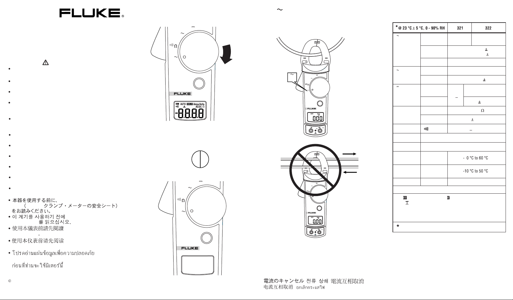
Read the 321, 322 Clamp Meter Safety Sheet
before using this meter.
Lisez la fiche de sécurité 321, 322 Clamp Meter
Safety Sheet avant d'utiliser cet appareil.
Prima di usare questo strumento, leggere il
documento 321, 322 Clamp Meter Safety Sheet.
Vor der Verwendung des Meßgeräts die
Sicherheitsinformationen zum 321, 322, Clamp
Meter lesen
Lea la hoja de instrucciones de seguridad "321, 322
Clamp Meter Safety Sheet" antes de utilizar este
medidor.
Leia "321, 322 Clamp Meter Safety Sheet" antesde
usar este medidor.
Lees het 321, 322 Clamp Meter Safety Sheet
voordat u deze meter gebruikt
Les 321, 322 Clamp Meter Safety Sheet før
måleinstrumentet tas i bruk.
Man skal læse "321, 322 Clamp Meter Safety Sheet"
inden man tager instrumentet i brug.
Lue 321, 322 Clamp Meter Safety Sheet ennen
tämän laitteen käyttöä.
Läs säkerhetsdatabladet "321, 322 Clamp Meter
Safety Sheet" innan du använder detta instrument.
Sheet
321, 322
Safety Sheet
Safety Sheet
Safety Sheet
321, 322 Clamp Meter Safety Sheet
PN 1615194 February 2002
2001, 2002 Fluke Corporation, All rights reserved. Printed in Taiwan.
www.fluke.com
Warning
321, 322 Clamp Meter Safety
321, 322 Clamp Meter
321, 322 Clamp Meter
321, 322 Clamp Meter
On/Off
V
V
MET
A
P
OFF
HOLD
AM
L
322
C
Automatic Off
30 Min
V
A
OFF
HOLD
AM
L
C
A
Specifications
Fluke 321 0 - 400.0 A
ER
V
ER
MET
P
322
Fluke 322 0 - 40.00 A, 40.0 - 400.0 A
CAT
A
COM
CAT
600V
400A
V
ER
V
MET
A
P
OFF
HOLD
AM
L
322
C
600V MAX
V
CAT
600V
400A
V
ER
V
MET
A
P
OFF
HOLD
AM
L
322
C
600V MAX
V
COM
CAT
Currents Cancel
Les courants s'annulent, Le correnti si cancellano,
A
V
V
Ω
Continuity
Jaw Opening
IP Rating
Storage
Temperature
Range
Accuracy
AC Response
Range
Accuracy
Range
Accuracy
Range
Accuracy
0 - 400.0 A
50 - 60 Hz 1.8% 5 counts
60 Hz - 400 Hz 3.0% 5 counts
50 - 400 Hz 1.2% 5 counts
1 inch or 26 mm
0 - 40.00 A
40.0 - 400.0 A
Avg
0 - 400.0, 400 - 600 V
0 - 400.0,
400 - 600 V
1% 5 counts
0 - 400.0
1.0% 5 counts
<
30 Ω
40
3
Operating
Temperature
Altitude
2000 m
EMC - EN61326
CAT III 600V, pollution degree II:
CAT III equipment is designed to protect against transients in
equipment in fixed - equipment installations, such as distribution
panels, feeders and short branch circuits, and lighting systems
in large buildings.
< 18 C, > 28 C add 0.1 x (specified accuracy)/ C.
Ströme abbrechen, Se cancelan las corrientes,
Cancelamento de correntes, Stromen compenseren
elkaar, Strømutjevning, Strømstyrkeannullering
Strømstyrker udbalancerer, Virta pois, Avbryt ström
,
,
,,
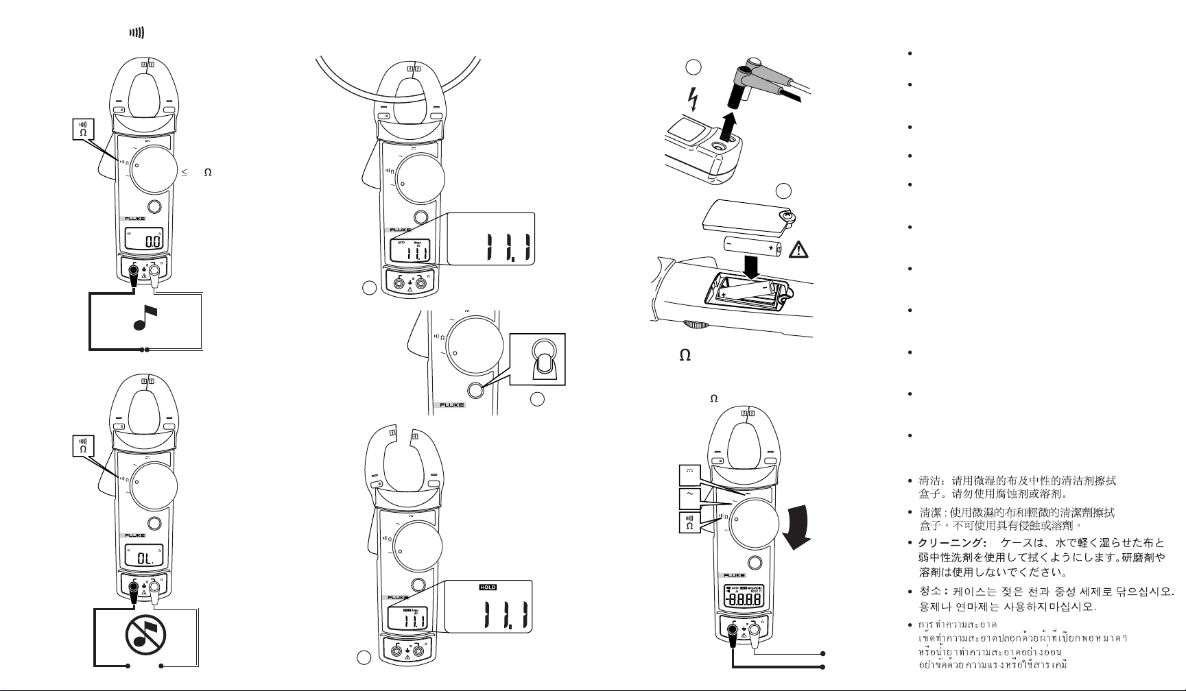
Continuity
Hold Battery Replacement
Cleaning
Wipe the case with a damp cloth and mild
1
detergent. Do not use abrasives or solvents.
Nettoyage : essuyer l'étui à l'aide d'un chiffon humide
CAT
600V
400A
CAT
600V
400A
et d'un détergent non-abrasif. Ne pas utiliser
d'abrasifs ou de solvents.
Pulizia : pulire l'involucro con un panno umido e un
V
A
V
OFF
HOLD
CLAMP METER
30
322
A
V
OFF
HOLD
CLAMP METER
V
2
AmpsAuto
322
AC
AAA
600V MAX
V
COM
CAT
600V MAX
V
COM
CAT
1
V
V
detergente neutro. Non usare né abrasivi né solventi.
Limpieza: Limpie la caja con un paño húmedo y un
detergente suave. No utilice abrasivos ni solventes.
Reinigung: Das Gehäuse mit einem feuchten
Lappen und mildem Reinigungsmittel abwischen.
Keine Scheuer- oder Lösungsmittel verwenden.
Limpeza: Para limpar a parte externa, use um pano
úmido com detergente neutro. Não use produtos
abrasivos nem solventes.
Reinigen: Veeg de behuizing af met een vochtige
doek en niet-agressief detergens. Gebruik geen
schuurmiddelen of oplosmiddelen.
Rengjøring: Tørk av huset med en fuktig klut og
mildt vaskemiddel. Bruk ikke skuremidler eller
løsemidler.
A
OFF
HOLD
322
CAT
600V
400A
CLAMP METER
HOLD
V,
0 - 600 V dc 322
0 - 600 V ac
2
0 - 400.0
Rengøring: Tør instrumenthuset af udenpå med en
fugtig klud og mildt sæbevand. Der må ikke benyttes
skure- og opløsningsmidler.
Puhdistaminen: Pyyhi kotelo kostealla kankaalla ja
miedolla pesuaineella. Älä käytä hankausaineita tai
liuottimia.
Rengöring: Torka av kåpan med en fuktad trasa och
ett milt rengöringsmedel. Använd inte nötande
rengöringsmedel eller lösningsmedel.
V
OFF
HOLD
CLAMP METER
600V MAX
600V
400A
V
322
V
CAT
V
V
600V
V
OFF
HOLD
CLAMP METER
600V MAX
400A
V
Amps
322
V
CAT
AC
A
OFF
HOLD
322
CLAMP METER
600V MAX
V
COM
CAT
CAT
A
COM
CAT
V
V
A
COM
3
(German)
W
Bitte zuerst lesen: Sicherheitshinweise
Vor Betrieb und Wartung des Meßgeräts bitte di e folge nde n
Sicherheitshinweise sorgfältig lesen:
• Wenn möglich, nicht allein arbeiten, damit Hilfestellung
gewährleistet werden kann.
• Das Meßgerät nicht bei Spannungen über 600 V oder
Frequenzen über 400 Hz Grundfrequenz be nutz e n, um
Geräteschäden zu vermeiden.
• Keine Strommessungen vornehme n, sol a nge Tes tl ei t unge n a n
den Eingangsbuchsen angeschlossen sind.
• Bei sichtbaren oder vermuteten Beschädigungen das
Meßgerät oder die Testleitunge n nic ht benutz e n.
• In der Nähe von Stromleitern und Sammelschie ne n ä ußer s te
Vorsicht walten lassen, da Berührungen elektrische Schläge
verursachen können.
• Vor dem Gebrauch die Anleitungskart e durchlesen und alle
Sicherheitshinweise befolgen.
• Das Meßgerät nur wie in der Anleitungskar te besc hrieben
benutzen, da sonst die Schutzvorr ic ht unge n des Gerä t s
beeinträchtigt werden können.
• Bei Gleichspannungen über 60 V und Wechsels pa nnunge n
über 30 V Vorsicht walten lassen, da derarti ge Spannunge n
eine Stromschlaggefahr darstellen.
Symbole
Die Anwendung im Bereich GEFÄHRLICHER
STROMFÜHRENDER Leiter sowie das Trennen von
,
solchen Leitern ist zulässig.
W
M
Gefahrenrisiko. Wichtige Informationen. Anleitungskarte
einsehen
Geräteschutz durch doppelte oder verstärkte Isolation
T
Batterielage
Entspricht CSA C22.2 Nr. 1010. 2.032-96
P
J
F
B
;
N10140
t
Dieses Fluke-Produkt ist für 2 Jahre ab Kaufdatum frei von Material- und
Fertigungsdefekten. Diese Garantie erstreckt sich nicht auf Sicherungen,
Einwegbatterien oder Schäden durch Unfälle, Fahrlässigkeit, Mißbrauch,
Änderungen oder abnor male Betriebsbedingu ng en bzw. unsachgemäße
Bedienung. Die Verkaufsstellen sind nicht dazu berechtigt, diese Garantie im
Namen von Fluke zu erweitern. Um die Garantieleistung in Anspruch zu
nehmen, wenden Sie sich an das nächstgelegene Fluke-Service-Center, um
Informationen zur Rücksendeautorisierung zu erhalten, und senden Sie das
Produkt anschließend mit einer Beschreibung des Problems an dieses
Service-Center.
DIESE GARANTIE IST IHR EINZIGER RECHTSANSPRUCH. KEINE
ANDEREN GARANTIEN, WIE DIE DER ZWECKDIENLICHKEIT FÜR EINEN
BESTIMMTEN EINSATZ, WERDEN AUSDRÜCKLICH ERTEILT ODER
IMPLIZIERT. FLUKE ÜBERNIMMT KEINE HAFTUNG FÜR AUS
IRGENDWELCHEN GRÜNDEN ODER RECHTSTHEORIEN
ABGELEITETEN SPEZIELLEN, MITTELBAREN, BEGLEIT- ODER
FOLGESCHÄDEN BEZIEHUNGSWEISE VERLUSTE.
Da in einigen Ländern der Ausschluß oder die Begrenzung von Begleit- oder
Folgeschäden nicht zulässig ist, kann es sein, daß die obengenannten
Haftungsbegrenzung für Sie nicht zutrifft.
Fluke Corporation
P.O. Box 9090
Everett, WA 98206-9090
U.S.A.
Übereinstimmung mit der Richtlinien der Europäischen
Union.
Erde
Gleichstrommessung
Wechselstrommessung
Entspricht den relevanten australischen Standards
Entspricht UL 3111-1 und UL 3111-2-032
Geprüft und lizenziert durch TÜV Product Services
Beschränkte Garantie & Haftungsbeschränkung
Fluke Europe B.V.
P.O. Box 1186
5602 BD Eindhoven
Niederlande
Bitte besuchen Sie www.fluke-warranty.com, um das
Produkt zu registrieren
11/99

321, 322
Clamp Meter
Safety Sheet
(English)
W
Read First: Safety Information
To ensure safe operation and service of the meter, follow
these instructions:
• Avoid working alone so assistance can be rendered.
• Never use the meter on a circuit with voltages higher than
600 V or a frequency higher than 400 Hz fundamental. The
meter may be damaged.
• Never measure current while the test leads are inserted into
the input jacks.
• Do not use the meter or test leads if they look damag ed .
• Use extreme caution when working around bare conduc t ors
or bus bars. Contact with the conductor could result in
electric shock.
• Read the instruction card before use and follow all safety
instructions.
• Use the meter only as specified in the instruction card;
otherwise, the meter’s safety features may not protect you.
• Use caution when working with voltages above 60 V dc or
30 V ac. Such voltages pose a shock hazard.
Symbols
Application around and removal from HAZARDOUS LIVE
,
conductors permitted.
W
M
F
B
;
N10140
t
Risk of danger. Important information. See instruction card
Equipment protected by double or reinforced insulation
T
Battery
Conforms to CSA C22.2 No 1010. 2.032-96
Conforms to EU directives
P
Earth
J
DC measurement
AC measurement
Conforms to relevant Australian standards
Conforms to UL 3111-1 and UL 3111-2-032
Inspected and licensed by TÜV Product Services
®
Limited Warranty and Limitation of Liability
This Fluke product will be free from defects in material and
workmanship for 2 years from the date of purchase. This warranty does
not cover fuses, disposable batteries, or damage from accident, neglect,
misuse, alteration, contamination, or abnormal conditions of operation
or handling. Resellers are not authorized to extend any other warranty
on Fluke’s behalf. To obtain service during the warranty period, contact
your nearest Fluke authorized service center to obtain return
authorization information, then send the product to that Service Center
with a description of the problem.
THIS WARRANTY IS YOUR ONLY REMEDY. NO OTHER
WARRANTIES, SUCH AS FITNESS FOR A PARTICULAR PURPOSE,
ARE EXPRESSED OR IMPLIED. FLUKE IS NOT LIABLE FOR ANY
SPECIAL, INDIRECT, INCIDENTAL OR CONSEQUENTIAL DAMAGES
OR LOSSES, ARISING FROM ANY CAU SE OR THEORY. Since some
states or countries do not allow the exclusion or limitation of an implied
warranty or of incidental or consequential damages, this limitation of
liability may not apply to you.
Fluke Corporation
P.O. Box 9090
Everett, WA 98206-9090
U.S.A.
To register your product, visit www.fluke-warranty.com
Fluke Europe B.V.
P.O. Box 1186
5602 BD Eindhoven
The Netherlands
11/99

ClampMeters
Calibration Information
Introduction
WWarning
To avoid electric shock or injury, do not perform the performance tests or
calibration procedures unless you are qualified to do so.
The information provided in this manual is for the use of qualified personnel
only.
The 32X Calibration Information provides the information necessary to verify the performance and adjust
the calibration of the Fluke 321 and 322 ClampMeters, hereafter known as the Meter(s).
®
32X
The following information is included in this document:
• Safety Information and International Electrical Symbols
• Specifications
• Replacing the Batteries
• Cleaning
• Performance Tests
• Calibration Adjustment
• User-Replaceable Parts and Accessories
• Warranty Statement
See the 321,322 Instruction Card for complete operating instructions.
Contact Information
To contact Fluke, call:
1-888-99-FLUKE (1-888-993-5853) in USA
1-800-36-FLUKE (1-800-363-5853) in Canada
+31 402-675-200 in Europe
+81-3-3434-0181 Japan
+65-738-5655 Singapore
+1-425-446-5500 in other countries
For additional information about Fluke, its products, and services, visit Fluke’s web site at:
www.fluke.com
To register this product, go to register.fluke.com
PN 1631636 October 2001 Rev.1, 12/03
© 2001-2003 Fluke Corporation. All rights reserved. Printed in U.S.A.
1
32x
Calibration Information
Safety Information
WWarnings and Precautions
To avoid possible electric shock or personal injury, and to avoid possible damage to the Meter
or the equipment under test, adhere to the following practices:
Avoid working alone so assistance can be rendered.
•
Never use the Meter on a circuit with voltages higher than 600 V or a frequency
•
higher than 400 Hz fundamental. The meter may be damaged.
Do not use the Meter or test leads if they look damaged.
•
Use extreme caution when working around bare conductors or bus bars. Contact
•
with the conductor could result in electric shock.
Read the instruction card and safety sheet before use and follow all safety instructions.
•
Use the Meter only as specified in the instruction card; otherwise, the Meter’s safety
•
features may be impaired.
Use caution when working with voltages above 60 V dc or 30 V ac. Such voltages
•
pose a shock hazard.
Before using the Meter, inspect the case. Do not use the Meter if it is damaged. Look for
•
cracks or missing plastic. Pay particular attention to the insulation around the connectors.
Verify the Meter’s operation by measuring a known voltage. Do not use the Meter if it
•
operates abnormally. Protection may be impaired. When in doubt, have the Meter serviced.
Do not apply more than the rated current or voltage, as marked on the Meter.
•
Use the proper terminals, function, and range for your measurements.
•
Do not operate the Meter with the case (or part of the case) removed.
•
When servicing the Meter, use only specified replacement parts.
•
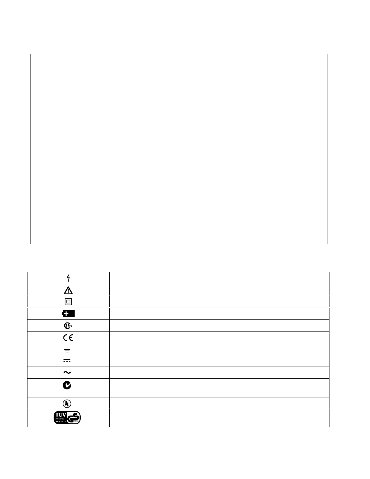
International Electrical Symbols
The following international symbols appear in this document and on the Meter.
N10140
Risk of electric shock
Risk of danger. Important Information. See manual.
Equipment protected by double or reinforced Insulation
Battery
Conforms to CSA C22.2 No 1010. 2.032-96
Conforms to EU directives
Earth
DC measurement
AC measurement
Conforms to relevant Australian standards
Conforms to UL 3111-1 and UL 3111-2-032
Inspected and licensed by TÜV Product Services
2

Specifications
*@ 23 °C ± 5 °C, 0 - 90% RH 321 322
ClampMeters
Specifications
?
(50/60 Hz)
Continuity R ≤ 30 Ω
Jaw Opening 1 inch (26 mm)
IP Rating 40
Storage Temperature -40 °C to 60 °C
Operating Temperature -10 °C to 50 °C
Altitude 2000 m
Range 0 - 400.0 A 0 - 40.0 A
40 .0 - 400.0 A
Accuracy 50 Hz - 60 Hz 1.8 % ± 5 counts
60 Hz - 400 Hz 3.0 % ± 5 counts
AC Response Avg
Range 0 - 400.0 V, 400 - 600 VK
Accuracy 50 Hz - 400 Hz 1.2 % ± 5 counts
Range 0 - 400.0 V, 400 - 600 VL
Accuracy
Range 0 - 400.0 Ωe
Accuracy 1.0 % ± 5 counts
_
1 % ± 5 counts
EMC- EN61326
CAT III 600 V, pollution degree II:
CAT III equipment is designed to protect against transients in equipment in fixed-equipment installations, such as
distribution panels, feeders and short branch circuits, and lighting syst ems in large buildings.
* < 18 °C, > 28 °C add 0.1 x (specified accuracy)/ °C
3
32x
Calibration Information
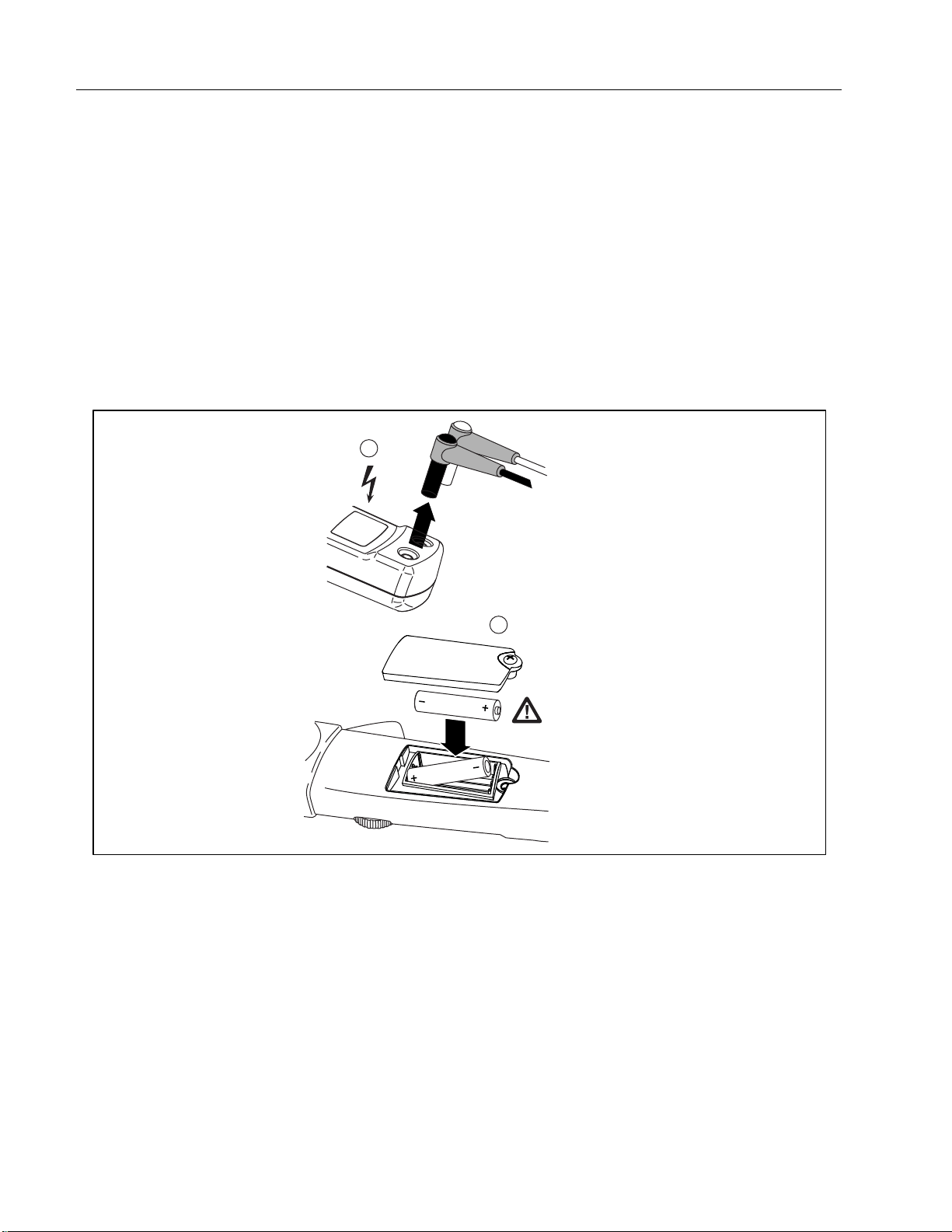
Replacing the Batteries
To avoid false readings, that could lead to possible electric shock or personal
injury, replace the batteries as soon as the low battery indicator (
Disconnect the test leads before replacing the batteries.
To replace the batteries (refer to Figure 1):
WWarning
b ) appears.
1. Turn the rotary switch to
OFF and remove the test leads from the terminals.
2. Loosen the battery compartment door screw, and remove the door from the case bottom.
3. Remove the batteries.
4. Replace the batteries with 2 new AAA batteries.
5. Reattach the battery compartment door to the case bottom and tighten the screw.
1
2
AAA
Figure 1. Replacing the Batteries
Cleaning
W Warning
To avoid electrical shock, remove any input signals before cleaning.
Caution
To avoid damaging the Meter, do not use aromatic hydrocarbons or chlorinated
solvents for cleaning. These solutions will react with the plastics used in the
instruments.
Clean the instrument case with a damp cloth and mild detergent.
4
ade02.eps
ClampMeters
Performance Tests
Performance Tests
WWarning
To avoid electric shock, do not perform the performance test procedures unless
the Meter is fully assembled.
The following performance tests verify the complete operation of the Meter and check the accuracy of
each meter function against the Meter’s specifications. If the Meter fails any part of the test, calibration
adjustment and/or repair is indicated.
In the performance tests, the Meter is referred to as the unit under test (UUT).
Table 1. Required Equipment
Equipment Minimum Specifications Recommended Model
AC Calibrator
50-Turn Current
Coil
DC Voltage: 0 to ±1020 V
AC Voltage: 1 mV to 1020 V, 10 Hz to 500 kHz, Sine
AC Current: 29 µA to 20.5 A, 10 Hz to 30 kHz, Sine
Ohms: 0 to 1100 MΩ
Uncertainty due to Clampmeter/ Coil Interaction: ± (0.25% of effective
output + 0.5A), for toroidal-wound current clamps, such as the Fluke
80I and 80I-1000.
± (0.50% of effective output + 0.5A), for current clamps like the Fluke
80i-kw, 80i-400, 80i-410, 80i-500, 80i-1010, Fluke 31, Fluke 33, or
equivalent.
Fluke 5520A
Fluke 5500A/Coil
Mirror
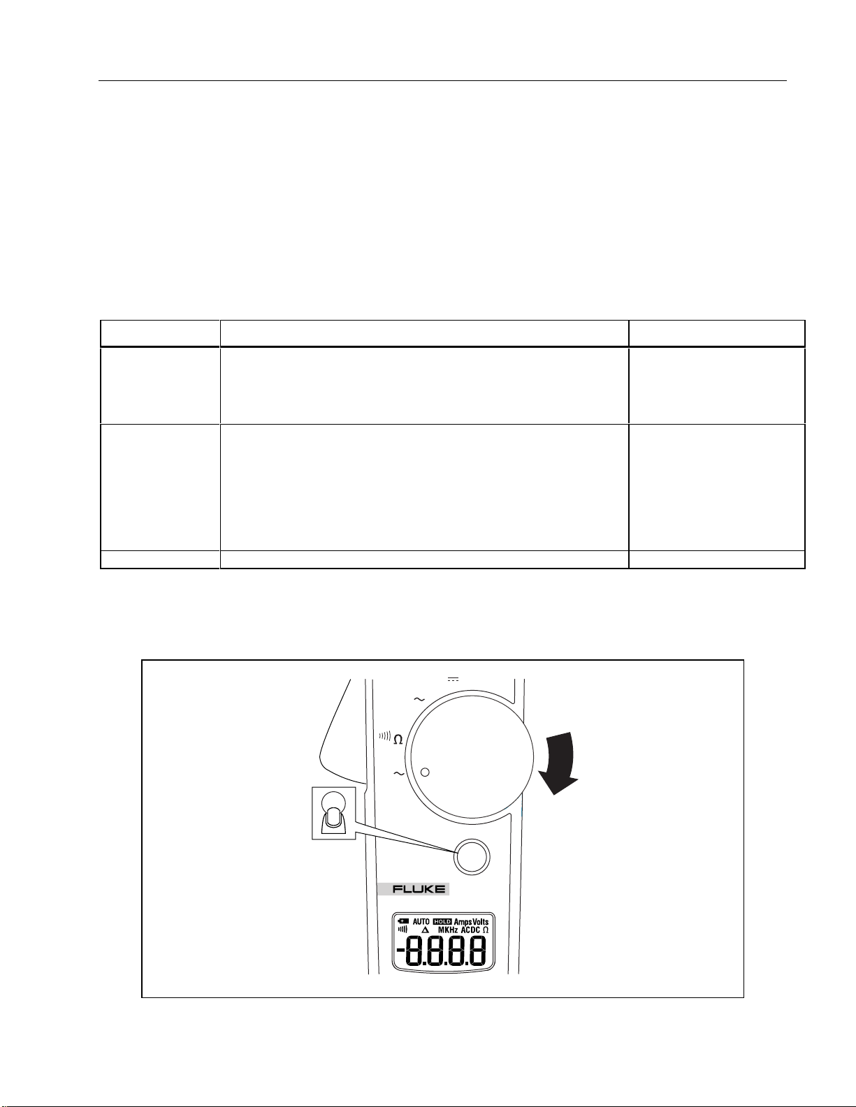
Testing the Display
Test the display by turning the Meter on while holding down the HOLD button. Check all segments for
clarity and contrast. Refer to Figure 2.
V
V
On/Off
A
OFF
HOLD
322
CLAMP METER
Figure 2. Testing the Display
ade01f.eps
5

32x
Calibration Information
Hold Button Test
To test the HOLD button, turn the Meter on and push the hold button. Each button push will cause the
Meter to beep.
Preparing for the Performance Test
WWarning
To avoid possible electric shock or personal injury:
Do not perform the following procedures unless qualified to do so. Some
•
procedures involve the use of high voltages.
Before handling the test connections and in between tests, make sure the
•
calibrator is in standby mode (STBY).
To prepare for the performance test:
1. Make sure that you have the required equipment, see Table 1.
2. Warm up the calibrator as required by its specifications.
3. Allow the temperature of the UUT to stabilize at room temperature ( 23 °C ± 5 °C [73 °F ± 9 °F] ).
6
ClampMeters
Performance Tests
Performance Test Procedure
To test each of the Meter’s functions and operating ranges, do the following:
1. Connect the source to the Meter’s VΩ and COM input jacks.
2. Referring to Table 2 for the 321 and Table 3 for the 322, put the Meter in the desired function and
range for each test.
3. Apply the indicated output from the 5520A Calibrator.
4. When using the amp function on the 5520A, make sure LCOMP on the 5520A is ON.
5. The reading on the Meter display should be within the low and high limits shown in the table.
6. Repeat steps 1-4 for each function and range in Table 2 or Table 3.
If the Meter fails to perform within the low-high range indicated for each test in Table 2 or Table 3, the
Meter needs to be calibrated and adjusted, or requires some repair.
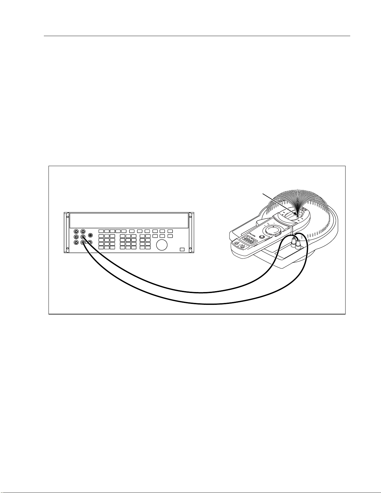
50-Turn Current Coil
Conductor
5520A Calibrator
Figure 3. 32x Amps/Hz Verification Setup
CAT
600V
V
A
OFF
HOLD
CLAMP METER
COM
322
600V MAX
CAT
V
400A
ade07f.eps
7
32x
Calibration Information
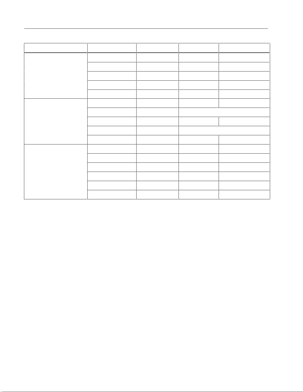
Table 2. Performance Tests 321
Functional Test 5520 output Nominal Low Limit High Limit
AC Amps
Ohms
AC Volts
0.7 A @ 50 Hz 35 A @ 50 Hz 33.8 36.2
0.7 A @ 400 Hz 35 A @ 400 Hz 33.4 36.6
6 A @ 60 Hz 300 A @ 60 Hz 294.1 305.9
7 A @ 50 Hz 350 A @ 50 Hz 343.2 356.8
7 A @ 400 Hz 350 A @ 400 Hz 339.0 361.0
30 Ohm 30 Ohms 29.2 30.8
Beeper must be on
50 Ohm 50 Ohms 49.0 51.0
Beeper must be off
350 Ohm 350 Ohms 346.0 354.0
35 V @ 50 Hz 35 V @ 50 Hz 34.0 36.0
350 V @ 60 Hz 350 V @ 60 Hz 345.3 354.7
600 V @ 60 Hz 600 V @ 60 Hz 592.3 607.7
35 V @ 400 Hz 35 V @ 400 Hz 34.0 36.0
350 V @ 400 Hz 350 V @ 400 Hz 345.3 354.7
600 V @ 400 Hz 600 V @ 400 Hz 592.3 607.7
8

Table 3. Performance Tests 322
Functional
Test 5520A Output Nominal Low Limit High Limit
ClampMeters
Performance Tests
AC Amps
Ohms
AC Volts
0.6 A @ 60 Hz 30 A @ 60 Hz 28.9 31.1
0.07 A @ 50 Hz 3.5 A @ 50 Hz 2.9 4.1
0.7 A @ 50 Hz 35 A @ 50 Hz 33.4 36.6
0.07 A @ 400 Hz 3.5 A @ 400 Hz 2.9 4.1
0.7 A @ 400 Hz 35 A @ 400 Hz 33.4 36.6
1 A @ 50 Hz 50 A @ 50 Hz 48.6 51.4
7 A @ 50 Hz 350 A @ 50 Hz 343.2 356.8
7 A @ 400 Hz 350 A @ 400 Hz 339.0 361.0
1 A @ 400 Hz 50 A @ 400 Hz 48.0 52.0
30 Ohm 30 Ohms 29.2 30.8
Beeper must be on
50 Ohm 50 Ohms 49.0 51.0
Beeper must be off
350 Ohm 350 Ohms 346.0 354.0
35 V @ 50 Hz 35 V @ 50 Hz 34.0 36.0
350 V @ 60 Hz 350 V @ 60 Hz 345.3 354.7
DC Volts
600 V @ 60 Hz 600 V @ 60 Hz 592.3 607.7
35 V @ 400 Hz 35 V @ 400 Hz 34.0 36.0
350 V @ 400 Hz 350 V @ 400 Hz 345.3 354.7
600 V @ 400 Hz 600 V @ 400 Hz 592.3 607.7
-350 V -350V -355.8 -344.2
35 V 35V 33.9 36.1
350 V 350V 344.2 355.8
600 V 600V 590.5 609.5
9

32x
Calibration Information
321 Calibration Adjustment
Use the following steps to adjust the calibration of the 321 (refer to Figure 4):
1. Remove the screws on the bottom of the Meter.
2. Lift off the top case.
3. Apply 600.0 V 50 Hz from the 5520A.
4. Adjust VR1 until display reads within 1.0 V.
5. Apply 4 A 50 Hz from the 5520A to the 50-turn coil. The 50-turn coil will make the meter read 200.0
A 50 Hz .
6. Adjust VR2 until the display reads within 0.5 A. A mirror will need to be used because the calibration
point cannot be seen from the top side of the meter.
7. Replace the top case.
8. Replace the case screws.
9. Verify the calibration by going through the performance test procedures.
10
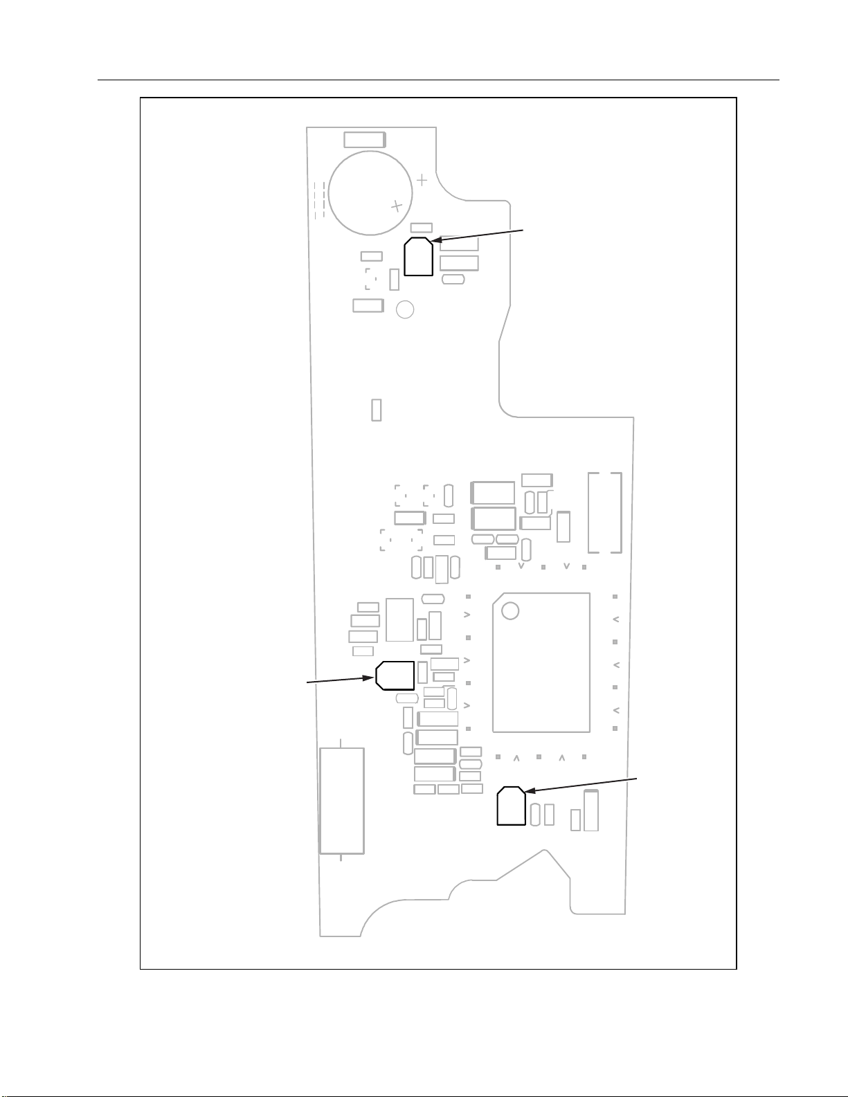
VR3
ClampMeters
Performance Tests
VR2
Figure 4. Calibration Adjustment Points (321)
VR1
ade05f.eps
11

32x
Calibration Information
322 Calibration Adjustment
Use the following steps to adjust the calibration of the meter (refer to Figure 5):
1. Turn the meter to DC V.
2. Remove the screws on the bottom of the Meter.
3. Lift off the top case.
4. Apply 300.0 V DC from the 5520A to the Meter..
5. Adjust VR1 until the UUT (Unit Under Test) display reads within 0.1 V.
6. Change the meter to the V AC function.
7. Apply 300 V @ 60 Hz.
8. Adjust VR2 until the UUT display reads within 0.1. V.
9. Change to the A AC function.
10. Apply 6 A 60 Hz to the 50-turn coil. The 50-turn coil will cause the Meter read this as 300.0 A 60Hz.
11. Adjust VR3 until this difference between steps 8 and 11 is within 0.1 A. A mirror will need to be used
because the calibration point cannot be seen from the top side of the meter.
12. Replace top case.
13. Verify the calibration by going through the Performance Test procedures.
12
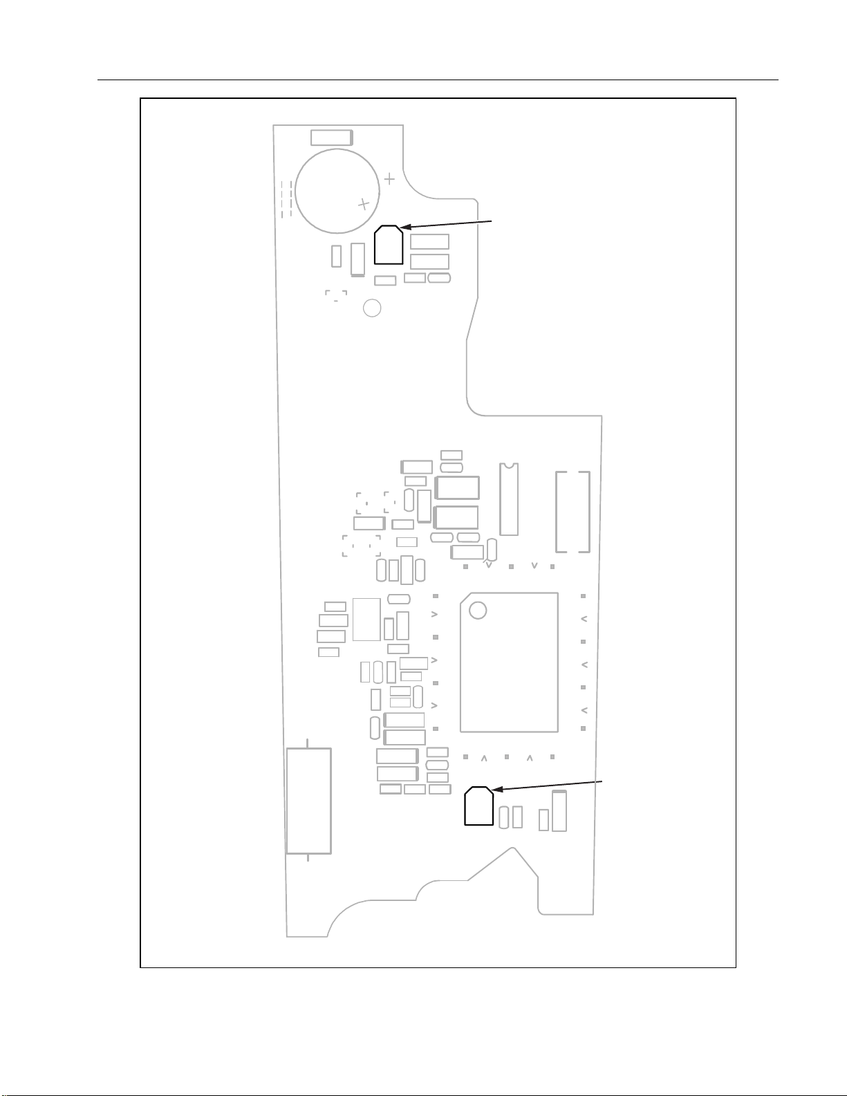
VR2
ClampMeters
Performance Tests
Figure 5. Calibration Adjustment Points 322
VR1
ade06f.eps
13
32x
Calibration Information
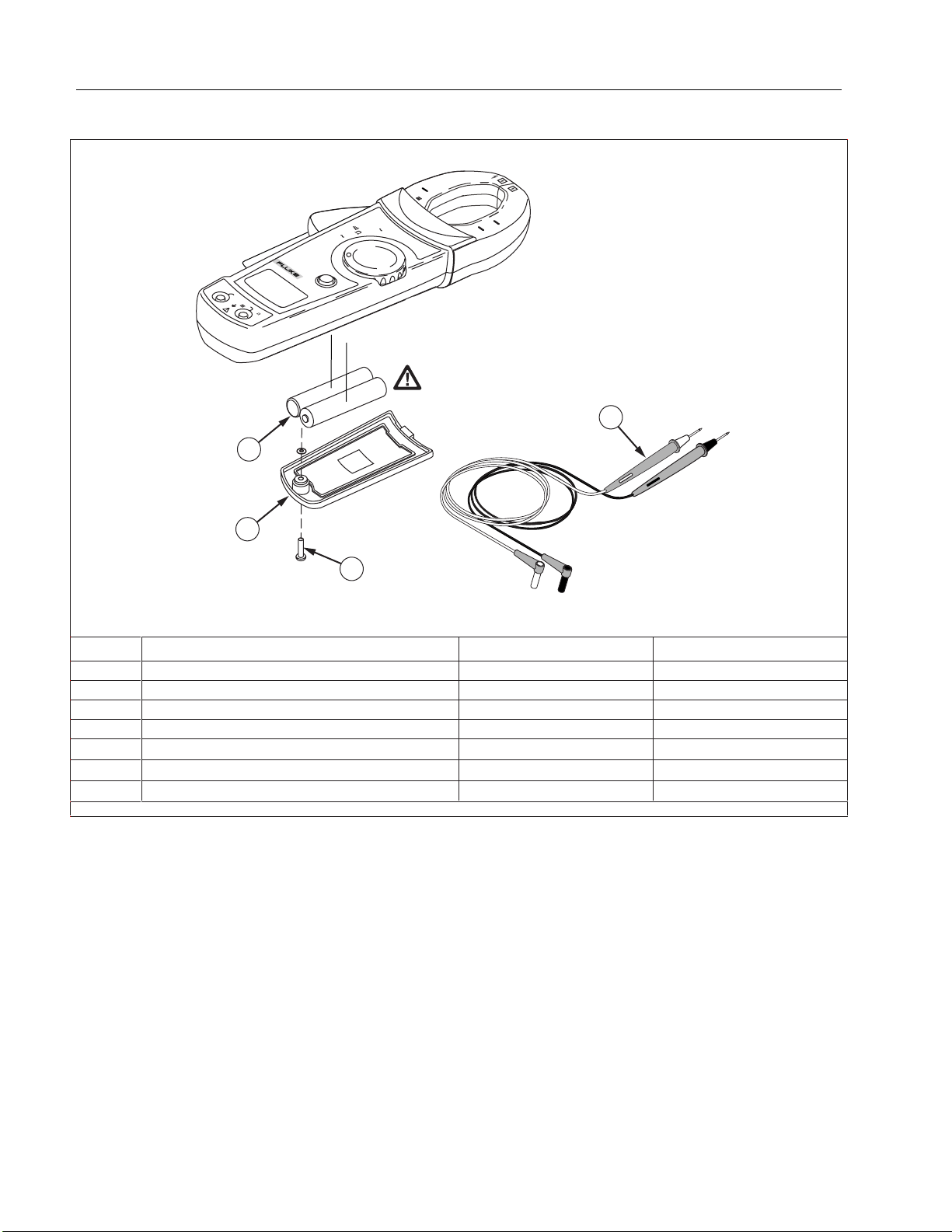
User-Replaceable Parts and Accessories
CAT
600V
V
A
OFF
HOLD
CLAMP METER
COM
600V MAX
CAT
322
V
1
400A
4
2
3
Item # Description Part No Qty
A
B
C
D
Not Shown
Not Shown
Not Shown
** Fluke accessories are available from your authorized Fluke dis t ribut or.
Battery,1.5V,0-150MA, AA Alkaline 376756 2
Battery Door 1630734 1
Battery Door Screw 1611694 1
TL75 Test Lead Set** 855705 1
321, 322 Safety Sheet
321, 322 Instruction Card
Calibration Information (this document)
1615215 1
1615194 1
1631636 1
Figure 6. User-Replaceable Parts and Accessories
ade08f.eps
14

ClampMeters
User-Replaceable Parts and Accessories
LIMITED WARRANTY AND LI M ITATION OF LIABILITY
This Fluke product is warranted to be free from defects in mat eri al and workmanship under normal use and servic e. The warranty period
is 2 years and begins on the date of shipment. Parts, product repairs, and services are warrant ed f or 90 days. This warranty extends only
to the original buyer or end-user customer of a Fluke authorized reseller, and does not apply to fuses, di sposable batteries, or to any
product which, in Fluke’s opinion, has been misused, altered, neglec ted, contaminated, or damaged by ac cident or abnormal conditions
of operation or handling. Fluke warrants that s of tware will operate substantially in accordance wit h its functional specificat ions for 90 days
and that it has been properly recorded on non-defect i v e media. Fluke does not warrant that software will be error f ree or operate without
interruption.
Fluke authorized resellers shall extend this warranty on new and unus ed products to end-user customers only but have no authority to
extend a greater or different warranty on behal f of Fluke. Warranty support i s available only if product is purchased through a Fluke
authorized sales outlet or Buyer has paid the applicable international price. Fluke reserves t he ri ght to invoice Buyer for im portation costs
of repair/replacement parts when product purchased in one country is submitted for repair in another country.
Fluke’s warranty obligation is limited, at Fluke’s option, to refund of the purchase price, free of c harge repai r, or replacement of a
defective product whic h i s returned to a Fluke authorized serv i c e center within the warranty period.
To obtain warranty service, contact your nearest Fluke aut hori zed service center to obtai n ret urn authorization information, then send the
product to that service center, with a descripti on of the difficulty, postage and insurance prepaid (FOB Destinat i on). Fluke assumes no
risk for damage in transit. Following warranty repair, the product will be returned to Buyer, trans port at i on prepaid (FOB Destination). If
Fluke determines that fai l ure was caused by neglect, misuse, contamination, al teration, accident, or abnormal condition of operation or
handling, including overvoltage failures caused by use outside the product’s specified rating, or normal wear and tear of mechani cal
components, Fluke will provide an estimate of repair costs and obtain authorization bef ore commencing the work. Following repair, the
product will be returned to the Buyer transport at i on prepaid and the Buyer will be billed for the repair and return transportation charges
(FOB Shipping Point).
THIS WARRANTY IS BUYER'S SOLE AND EXCLUSIVE REMEDY AND IS IN LIEU OF ALL OTHER WARRANTIES, EXPRESS OR
IMPLIED, INCLUDI NG B UT NOT LIMITED TO ANY IMPLIED WARRANTY OF MERCHA NT ABILITY OR FITNESS FOR A PARTICULAR
PURPOSE. FLUKE SHALL NOT BE LIABLE FOR ANY SPECIAL, INDIRECT, INCIDENTAL OR CONSEQUENTIAL DAMAGES OR
LOSSES, INCLUDING LOSS OF DATA, ARISING FROM ANY CAUSE OR THEORY.
Since some countries or states do not allow limit ation of the term of an implied warrant y, or exclusion or limit ation of incidental or
consequential damages, the l i mitations and exclusi ons of this warranty may not apply to every buyer. If any provision of this Warranty i s
held invalid or unenforceable by a court or other decis ion-maker of competent jurisdiction, s uc h holding will not affect the validity or
enforceability of any other provision.
Fluke Corporation
P.O. Box 9090
Everett, WA 98206-9090
U.S.A.
Fluke Europe B.V.
P.O. Box 1186
5602 BD Eindhoven
The Netherlands
11/99
To register this product, go to www.register.fluke.com
15

32x
Calibration Information
16

Models 110, 111 & 112
Bedienungshandbuch
True RMS Multimeters
®
November 2000 (German), Rev 1, 7/01
© 2000-2001 Fluke Corporation. All rights reserved. Printed in USA.

Begrenzte Gewährleistung und Haftungsbeschränkung
Fluke gewährleistet, daß jedes Fluke-Produkt unter normalem Gebrauch und Service frei von Material- und Fertigungsdefekten ist. Die Garantiedauer beträgt
3 Jahre ab Versanddatum. Ersatzteile, Produktreparaturen und Servicearbeiten haben eine Garantie von 90 Tagen. Diese Garantie wird ausschließlich dem
Ersterwerber bzw. dem Endverbraucher, der das betreffende Produkt von einer von Fluke autorisierten Verkaufsstelle erworben hat, geleistet und erstreckt sich
nicht auf Sicherungen, Einwegbatterien oder irgendwelche anderen Produkte, die nach dem Ermessen von Fluke unsachgemäß verwendet, verän de rt,
vernachlässigt, verunreinigt, durch Unfälle beschädigt oder abnormalen Betriebsbedingungen oder einer unsachgemäßen Handhabung ausgesetzt wurden.
Fluke garantiert für einen Zeitraum von 90 Tagen, daß die Software im wesentlichen in Übereinstimmung mit den einschlägigen Funktionsbeschreibungen
funktioniert und daß diese Software auf fehlerfreien Datenträgern gespeichert wurde. Fluke übernimmt jedoch keine Garantie dafür, daß die Software fehlerfrei
ist und störungsfrei arbeitet.
Von Fluke autorisierte Verkaufsstellen werden diese Garantie ausschließlich für neue und nicht benutzte, an Endverbraucher verkaufte Produkte leisten. Die
Verkaufsstellen sind jedoch nicht dazu berechtigt, diese Garantie im Namen von Fluke zu verlängern, auszudehnen oder in irgendeiner ander en W eis e
abzuändern. Der Erwerber hat nur dann das Recht, aus der Garantie abgeleitete Unterstützungsleistungen in Anspruch zu nehmen, wenn er das Produkt bei
einer von Fluke autorisierten Vertriebsstelle gekauft oder den jeweils geltenden internationalen Preis gezahlt hat. Fluke behält sich das Recht vor, dem Erwerber
Einfuhrgebühren für Reparatur/Ersatzteile in Rechnung zu stellen, wenn dieser das Produkt in einem anderen Land zur Reparatur anbietet, als dem Land, in
dem er das Produkt ursprünglich erworben hat.
Flukes Garantieverpflichtung beschränkt sich darauf, daß Fluke nach eigenem Ermessen den Kaufpreis ersetzt oder aber das defekte Produkt unentgeltlich
repariert oder austauscht, wenn dieses Produkt innerhalb der Garantiefrist einem von Fluke autorisierten Servicezentrum zur Reparatur üb erg eb en wi rd .
Um die Garantieleistung in Anspruch zu nehmen, wenden Sie sich bitte an das nächstgelegene von Fluke autorisierte Servicezentrum, um Rücknahmeinformationen zu erhalten, und senden Sie dann das Produkt mit einer Beschreibung des Problems und unter Vorauszahlung von Fracht- und Versicherungskosten
(FOB Bestimmungsort) an das nächstgelegene von Fluke autorisierte Servicezentrum. Fluke übernimmt keine Haftung für Transportschäden. Im Anschluß an
die Reparatur wird das Produkt unter Vorauszahlung der Frachtkosten (FOB Bestimmungsort) an den Käufer zurückgesandt. Wenn Fluke feststellt, daß der
Defekt auf Vernachlässigung, unsachgemäße Handhabung, Verunreinigung, Veränderungen am Gerät, einen Unfall oder auf anormale Betriebsbedingungen,
einschließlich durch außerhalb der für das Produkt spezifizierten Belastbarkeit verursachter Überspannungsfehler oder normaler Abnutzung mechanischer
Komponenten, zurückzuführen ist, wird Fluke dem Erwerber einen Voranschlag der Reparaturkosten zukommen lassen und erst die Zustimmung des Erwerbers
einholen, bevor die Arbeiten in Angriff genommen werden. Nach der Reparatur wird das Produkt unter Vorauszahlung der Frachtkosten an den Käufer
zurückgesendet, und es werden dem Käufer die Reparaturkosten und die Versandkosten (FOB Versandort) in Rechnung gestellt.
DIE VORSTEHENDEN GARANTIEBESTIMMUNGEN STELLEN DEN EINZIGEN UND ALLEINIGEN RECHTSANSPRUCH AUF SCHADENERSATZ DES
ERWERBERS DAR UND GELTEN AUSSCHLIESSLICH UND AN STELLE VON ALLEN ANDEREN VERTRAGLICHEN ODER GESETZLICHEN
GEWÄHRLEISTUNGSPFLICHTEN, EINSCHLIESSLICH - JEDOCH NICHT DARAUF BESCHRÄNKT - DER GESETZLICHEN GEWÄHRLEISTUNG DER
MARKTFÄHIGKEIT UND DER ZWECKDIENLICHKEIT FÜR EINEN BESTIMMTEN EINSATZ. FLUKE HAFTET NICHT FÜR SPEZIELLE, UNMITTELBARE,
MITTELBARE, BEGLEIT- ODER FOLGESCHÄDEN ODER VERLUSTE, EINSCHLIESSLICH VERLUST VON DATEN, UNABHÄNGIG VON DER URSACHE
ODER THEORIE.
Angesichts der Tatsache, daß in einigen Ländern die Begrenzung einer gesetzlichen Gewährleistung sowie der Ausschluß oder die Begrenzung von Begleitoder Folgeschäden nicht zulässig ist, kann es sein, daß die obengenannten Einschränkungen und Ausschlüsse nicht für jeden Erwerber gelten. Sollte eine
Klausel dieser Garantiebestimmungen von einem zuständigen Gericht oder einer anderen Entscheidungsinstanz für unwirksam oder nicht durchs etzbar
befunden werden, so bleiben die Wirksamkeit oder Durchsetzbarkeit anderer Klauseln dieser Garantiebestimmungen von einem solchen Spruch unberührt.
Fluke Corporation
P. O. Box 9090
Everett, WA 98206-9090
USA
Fluke Europe B.V.
P. O. Box 1186
5602 BD Eindhoven
Niederlande
11/99

Inhaltsverzeichnis
Vor Gebrauch des Meßgeräts lesen: Warnungen und Sicherheitshinweise.......................... ii
Kontaktaufnahme mit Fluke................................................................................................... 1
Warnungen und Vorsichtshinweise ....................................................................................... 1
Unsichere Spannung............................................................................................................. 1
Prüfleiteralarm....................................................................................................................... 1
Batteriesparmodus (Ruhemodus).......................................................................................... 2
Anschlüsse............................................................................................................................ 2
Drehschalterpositionen ......................................................................................................... 2
Anzeige................................................................................................................................. 3
MIN-MAX-AVG-Aufzeichnungsmodus................................................................................... 4
Anzeigehaltemodus (H OLD) ................................................................................................. 4
Hintergrundbeleuchtung (nur Modell 112) ............................................................................. 4
Manuelle und automatische Bereichswahl ............................................................................ 5
Einschaltoptionen.................................................................................................................. 5
Grundlegende Meßfunkt ionen............................................................................................... 6
Messen von Wechselspannung und Gleichspannung...................................................... 6
Messen von Widerstand ................................................................................................... 7
Messen von Kapazität...................................................................................................... 7
Kontinuitätsprüfungen ...................................................................................................... 7
Prüfen von Dioden ........................................................................................................... 8
Messen von Wechselstromstärke und Gleichstromstärke (Modelle 111 und 112)............ 8
Messen von Frequenz...................................................................................................... 9
Verwendung der Balkenanzeige............................................................................................ 9
Reinigung.............................................................................................................................. 9
Prüfen der Sicherung (Modelle 111 und 112)........................................................................ 10
Ersetzen der Batterie und Sicherung..................................................................................... 10
Spezifikationen...................................................................................................................... 11
Überschrift Seite
i

Models 110, 111 & 112
Bedienungs-Handbuch
W
Zur Vermeidung von Stromschlag oder Verletzungen folgende Richtlinien einhalten:
• Das Meßgerät ausschließlich wie in diesem Handbuch beschrieben einsetzen, da sonst die im Meßgerät integrierten
Schutzeinrichtungen beeinträchtigt werden könnten.
• Das Meßgerät nicht benutzen, wenn das Meßgerät oder die Prüfleitungen äußerliche Beschädigungen aufweisen oder wenn
das Meßgerät nicht einwandfrei funktioniert.
• Immer die richtigen Anschlüsse, die richtige Drehschalterposition und den richtigen Bereich für die jeweils anstehende
Messung auswählen.
• Die Funktion des Meßgeräts durch Messen einer bekannten Spannung überprüfen. Das Meßgerät im Zweifelsfall warten
lassen.
• Zwischen den Anschlüssen bzw. zwischen den Anschlüssen und Erde nie eine Spannung anlegen, die die am Meßgerät
angegebene Nennspannung überschreitet.
• Bei Spannungen über 30 V Wechselspannung rms, 42 V Wechselspannung Spitze oder 60 V Gleichspannung besondere
Vorsicht walten lassen. Bei solchen Spannungen besteht Stromschlaggefahr.
• Zur Vermeidung falscher Ablesungen, die zu Stromschlag oder Verletzungen führen können, die Batterie ersetzen, sobald
die Anzeige für schwache Batterie (N) eingeblendet wird.
• Vor dem Prüfen von Widerstand, Kontinuität, Dioden oder Kapazität den Strom des Stromkreises abschalten und alle
Hochspannungskondensatoren entladen.
• Das Meßgerät nicht in Umgebungen mit explosiven Gasen oder Dampf betreiben.
• Bei der Verwendung von Prüfleitern oder Prüfspitzen müssen die Finger hinter dem Fingerschutz bleiben.
• Vor dem Öffnen des Meßgerätgehäuses oder der Batteriefachabdeckung die Prüfleitungen abnehmen.
Vor Gebrauch des Meßgeräts lesen: Warnungen und Sicherheitshinweise
Symbole
B Wechselstrom (AC - Alternating Current) I Sicherung
F Gleichstrom (DC - Direct Current) P Übereinstimmung mit den Richtlinien der Europäischen Union.
D Wechselstrom oder Gleichstrom Canadian Standards Association
J Erde, Masse
W Wichtige Informationen, siehe Handbuch.
Batterie (Batterie schwach, wenn eingeblendet).
N
Geprüft und lizenziert durch TÜV Product Services
T
t
950 Z Listed
;
N10140
ii
Schutzisoliert
Underwriters Laboratories, Inc.
Stimmt mit den relevanten Australischen Normen überein.

Models 110, 111 & 112
True RMS Multimeters
g
Die Fluke True RMS Multimeter (Modell 110, Modell 111 und
Modell 112) sind batteriebetriebene Effektivwert-Multimeter
(hiernach “Meßgerät” genannt) mit 6000-Zählwerk und
Balkenanzeige. Dieses Handbuch gilt für alle drei Modelle. Alle
Abbildungen zeigen das Modell 112.
Das Meßgerät dient für folgende Messungen oder Prüfungen:
• Wechsel-/Gleichspannung und Wechsel-/Gleichstromstärke
• Widerstand
• Kontinuität
• Dioden
• Spannungs- und Stromfrequenz
• Kapazität
Diese Meßgeräte erfüllen CAT III IEC 61010-1-95-Standards. Der
Sicherheitsstandard IEC 61010-1-95 definiert vier Überspannungskategorien (CAT I bis IV) basierend auf der durch
Störimpulse verursachten Gefahr. CAT III-Meßgeräte sind so
konzipiert, daß sie auf Verteilerebene gegen impulsförm i ge
Störsignale in festinstallierten Geräten schützen.
Kontaktaufnahme mit Fluke
Fluke-Rufnummern:
(+1) 1 888 993 5853 - USA und Kanada
(+31) 402-678-200 - Europa
(+81) 3 3434 0181 - Japan
(+65) 738 5655 - Singapur
(+1) 425 446 5500 - weltweit
Fluke-Website: www.fluke.com.
Registrierung des Meßgerätes: www.fluke-warranty.com.
“Warnungen” und “Vorsichtshinweise”
Eine “WWarnung” identifiziert gefährliche Bedingungen und
Aktivitäten, die Körperverletzungen oder Tod verursachen können.
“Vorsicht” identifiziert Bedingungen und Aktionen, die das
Meßgerät oder die zu prüfende Ausrüstung beschädigen können.
Unsichere Spannung
Dieser Alarm signalisiert das Vorhandensein einer pot enti ell
gefährlichen Spannung. Das Symbol
Meßgerät eine Spannung ≥ 30 V oder eine Überspannung (OL)
feststellt.
Prüfleiteralarm
Das Messen mit einem Prüfleiter an einem falschen
Anschluß kann das Meßgerät beschädigen oder
Körperverletzungen verursachen.
LEAd
richtigen Anschlüssen angeschlossen si nd, kurz angez ei gt, wenn
der Drehschalter in eine beliebige A-Position oder von
A-Position in eine andere Position geschaltet wird.
Y wird angezeigt, wenn das
W
Warnung
wird als Erinnerung zum Prüfen, ob die Prüfleiter an den
einer
1

Models 110, 111 & 112
Bedienungshandbuch
Batteriesparmodus (“Ruhemodus”)
Das Meßgerät wechselt automatisch in den “Ruhemodus” und
löscht die Anzeige, wenn das Gerät eingeschaltet ist und
20 Minuten lang nicht gebraucht wird. Um den Ruhemodus zu
deaktivieren, die Taste Hz beim Einschalten des Meßgeräts
gedrückt halten. Der Ruhemodus ist im MIN-MAX-AVG-Modus
immer deaktiviert.
Anschlüsse
10 A
FUSED
COMAV
3
aej01f.eps
1
2
Nr. Beschreibung
Eingang für Wechselstrom- und Gleichstrommessungen
1
bis 10 A bzw. 20 A Überlast für bis zu 30 Sekunden und
für Frequenz des Stroms.
Gemeinsame Rückleitung für alle Messungen.
2
Eingang für Spannungs-, Kontinuitäts-, Widerstands-,
3
Kapazitäts- und Spannungsfrequenzmessungen sowie
Diodenprüfung.
Drehschalterpositionen
Schalterposition Meßfunktion
K
Hz (Taste)
L
Hz (Taste)
R
e
G
E
(Modelle 111 und 112)
?
Hz (Taste)
(Modelle 111 und 112)
A
Hz (Taste)
Hinweise: Wechselspannung und Wechselstromstärke wechselstrom-
gekoppelt, Effektivwert, bis 500 Hz.
Wechselspannung von 300 mV bis 600 V.
Frequenz von 5 Hz bis 50 kHz.
Gleichspannung von 1 mV bis 600 V.
Frequenz von 5 Hz bis 50 kHz.
Piepser aktiviert bei < 20 Ω, deaktiviert bei
> 250 Ω.
Widerstand von 0,1 Ω bis 40 MΩ.
Diodenprüfung. Zeigt OL oberhalb von
2,4 V an.
Farad von 1 nF bis 9999 µF.
Wechselstrom von 3 A bis 10 A.
(20 A Überlast für 30 Sekunden maximal.)
>10,00-Anzeige blinkt.
>20 A, OL wird angezeigt.
Frequenz von 50 Hz bis 5 kHz.
Gleichstrom von 0,001 A bis 10 A.
(20 A Überlast für 30 Sekunden maximal.)
>10,00-Anzeige blinkt.
>20 A, OL wird angezeigt.
Frequenz von 50 Hz bis 5 kHz.
2

True RMS Multimeters
Anzeige
Anzeige
5
4
3
2
1
13
Nr. Symbol Bedeutung
1
2
3
4
5
6
7
12
s
R
O
Y
K
M
X W V
nµF
mVA
Mk
e
kHz
6
11
14
Meßgerät ist auf Kontinuitätsfunktion
eingestellt.
Diodenprüfung.
Negative Meßwerte.
Unsichere Spannung. Spannung
≥ 30 V oder Spannungsüberlastbedingung (OL).
Anzeigehaltemodus (HOLD) ist
aktiviert. Anzeige friert aktuellen
Meßwert ein.
Im MIN-MAX-AVG-Modus ist MINMAX-AVG-Aufzeichnung pausiert.
MIN MAX AVG ist akti vie r t.
Höchst-, Niedrigst- oder
Durchschnittsmeßwert
Meßeinheiten.
Nr. Symbol Bedeutung
8
DC AC
9
N
7
8
7
9
10
15
aej02f.eps
10
610000 mV
11
(Balkenanzeige)
12 Auto Range
Manual Range
13
±
14
0L
15
LEAd
diSC
EEPr
EEPr
Err
CAL
Err
Wird angezeigt, während der Kondensator
entladen wird. Nur in der Funktion Kapazität.
Daten vom EEPROM können nicht gelesen
werden. Den Betriebsschalter aus-, dann wieder
einschalten. Wird die Nachricht weiter angezeigt,
das Meßgerät reparieren lassen.
Ungültige EEPROM-Daten. Das Meßgerät
reparieren lassen.
Ungültige Kalibrierdaten. Das Meßgerät
kalibrieren.
Gleichstrom (DC), Wechselstrom (AC).
Batterie unverzüglich ersetzen.
Alle möglichen Segmente des
Bereichanzeigers.
Analoganzeige.
Automatische Bereichswahl: das
Meßgerät wählt den Bereich mit
der besten Auflösung aus.
Manuelle Bereichswahl: Der
Bediener wählt den Bereich aus.
Balkenanzeigepolarität.
Der Eingang überschreitet den
ausgewählten Bereich.
W
Prüfleiteralarm.
Wird kurz angezeigt, wenn der
Drehschalter in eine beliebige
A-Position oder von einer
A-Position in eine andere Position
geschaltet wird.
Fehlermeldungen
3

Models 110, 111 & 112
Bedienungshandbuch
MIN-MAX-AVG-Aufzeichnungsmodus
Im MIN-MAX-AVG-Aufzeichnungsmodus werden die niedrigsten
und die höchsten Eingangswerte aufgezeichnet und der laufende
Durchschnitt aller Meßwerte berechnet. Wenn ein neuer Höchstoder Niedrigstwert gemessen wird, piepst das Meßgerät.
Am Meßgerät die gewünschte Funktion und den gewünschten
Bereich einstellen.
⇒ MIN MAX drücken, um den MIN-MAX-AVG-Modus zu
aktivieren.
M
Aktivierung des MIN-MAX-AVG-Modus gemessene Meßwert
wird angezeigt.
⇒ Die Taste MIN MAX drücken, um der Reihe nach den
Niedrigstwert (MIN), den Durchschnittswert (AVG) und den
aktuellen Wert anzuzeigen.
⇒ Um die MIN-MA X -AV G -Aufz eic hnung zu pausieren, ohne
aufgezeichnete Werte zu löschen, HOLD drücken.
wird angezeigt.
⇒ Um die MIN-MA X -AV G -Aufz eic hnung zu reaktivieren, HOLD
noch einmal drücken.
⇒ Um den Modus zu beenden und gespeicherte Werte zu
löschen, MIN MAX mindestens 1 Sekunde lang drücken oder
den Drehschalter drehen.
und MAX werden angezeigt, und der höchste seit
K
Anzeigehaltemodus (HOLD)
W
Warnung
Zur Vermeidung von Stromschlag bei aktiviertem
Anzeigehaltemodus (HOLD) beachten, daß sich die
Anzeige nicht verändert, wenn eine andere Spannung
angelegt wird.
Im Anzeigehaltemodus HOLD friert das Meßgerät die Anzeige ein.
⇒ HOLD drücken, um den Anzeigehaltemodus zu aktivieren.
K
(
wird angezeigt.)
⇒ Um zu beenden und zu Normalbetrieb zurückzukehren,
HOLD drücken oder den Drehschalter in eine andere Position
drehen.
Hintergrundbeleuchtung (nur Modell 112)
T
drücken, um die Hintergrundbeleuchtung ein- bzw.
auszuschalten. Die Hintergrundbeleuchtung wird nach 2 Minuten
automatisch ausgeschaltet.
Um die automatische 2-Minuten-Hintergrundbeleuchtungsabschaltung zu deaktivieren, die Taste T beim Einschalten des
Meßgeräts gedrückt halten.
4

True RMS Multimeters
Manuelle und automatische Bereichswahl
Manuelle und automatische Bereichswahl
Das Meßgerät verfügt über manuelle und automatische
Bereichswahl.
⇒ Im Modus “Automatische Bereichswahl” wählt das Meßgerät
den Bereich mit der besten Auflösung aus.
⇒ Im Modus “Manuelle Bereichswahl”, der den automatischen
Modus übersteuert, wählt der Bediener den Bereich aus.
Unmittelbar nach dem Einschalten befindet sich das Meßgerät im
automatischen Modus und zeigt Auto Range an.
1. Um die manuelle Bereichswahl zu aktivieren, die Taste
RANGE drücken. Manual Range wird angezeigt.
2. Im Modus “Manuelle Bereichswahl” RANGE drücken, um den
Bereich zu erhöhen. Nach dem höchsten Bereich zeigt das
Meßgerät wieder den niedrigsten Bereich an.
Hinweis
Der Bereich kann im MIN-MAX-AVG- und
Anzeigehaltemodus HOLD nicht manuell verändert werden.
Wenn
RANGE
Anzeigehaltemodus HOLD gedrückt wird, piepst das
Meßgerät, um eine ungültige Bedienung zu signalisieren,
und der Bereich bleibt unverändert.
3. Um die manuelle Bereichswahl zu beenden, RANGE
mindestens 1 Sekunde lang drücken oder den Drehschalter
drehen.
Das Meßgerät kehrt zu automatischer Bereichswahl zurück
und Auto Range wird angezeigt.
im MIN-MAX-AVG- oder
Einschaltoptionen
Um eine Einschaltoption zu aktivieren, die entsprechende Taste
beim Einschalten des Meßgeräts mindestens 1 Sekunde gedrückt
halten.
Einschaltoptionen werden deaktiviert, wenn das Meßgerät
ausgeschaltet wird.
Taste Einschaltoptionen
HOLD
MIN MAX
Hz
S
Schaltet alle Anzeigesegmente ein.
HOLD loslassen, um fortzufahren; die
Softwareversionsnummer wird kurz angezeigt, und
das Meßgerät kehrt zu Normalbetrieb zurück.
Deaktiviert Piepser.
Deaktiviert die automatische Ausschaltfunktion
(“Ruhemodus”).
Deaktiviert die automatische 2-MinutenHintergrundabschaltung. (Nur Modell 112.)
5

Models 110, 111 & 112
Bedienungshandbuch
Grundlegende Meßfunktionen
Die Abbildungen auf den folgenden Seiten zeigen, wie
grundlegende Meßfunktionen durchgeführt werden.
Beim Anklemmen der Prüfleitungen an den Stromkreis oder das
Gerät den gemeinsamen Prüfleiter (COM) vor der spannungs-
führenden Leitung anschließen. Beim Abklemmen der
Prüfleitungen die spannungsführende Prüfleitung vor der
gemeinsamen Prüfleitung abtrennen.
W
Warnung
Zur Vermeidung von Stromschlägen, Verletzungen oder
Schäden am Meßgerät vor Widerstands-, Kontinuitäts-,
Dioden- oder Kapazitätsprüfungen sicherstellen, daß
die Netzstromverbindung abgetrennt ist und alle
Hochspannungskondensatoren entladen sind.
Hinweis
Beim Ablesen von Wechselspannung oder -stromstärke
(zum korrekten Messen verzerrter Signalformen durch den
integrierten RMS-Wandler) steigt die Meßwerteinschwingzeit am unteren Ende der Wechselspannungs- und
Wechselstromstärkebereiche auf mehrere Sekunden.
Das Meßgerät ist nicht zur Verwendung mit
Stromklemmenzubehör ausgelegt.
Messen von Wechselspannung und Gleichspannung
V Wechselspannung
V
V Gleichspannung
V
aej03f.eps
6

True RMS Multimeters
Grundlegende Meßfunktionen
Messen von Widerstand
Messen von Kapazität
aej04f.eps
Kontinuitätsprüfungen
Hinweis
Die Kontinuitätsfunktion ist die beste Methode zum
schnellen, bequemen Prüfen von offenen Schaltungen und
Kurzschlüssen. Für maximale Genauigkeit beim Messen
(e)
von Widerstand die Widerstandsfunktion
des Meßgeräts
verwenden.
aej06f.eps
aej05f.eps
7

Models 110, 111 & 112
Bedienungshandbuch
Prüfen von Dioden
Gute Diode Gute Diode
Vorwärts-Bias
Schlechte Diode
Offen
Einzelpiepton
Rückwärts-Bias
Schlechte Diode
und
kurzgeschlossen
aej07f.eps
Messen von Wechselstromstärke und Gleichstromstärke
(Modelle 111 und 112)
W
Warnung
Zur Vermeidung von Verletzungen und Beschädigung
des Meßgeräts folgende Vorschriften einhalten:
• Unter keinen Umständen eine Schaltkreismessung
vornehmen, wenn das Ruhepotential zur Masse
> 600 V beträgt.
• Vor Gebrauch die Sicherung des Meßgeräts prüfen.
(Siehe “Prüfen der Sicherung”.)
• Die richtigen Anschlüsse, die richtige
Drehschalterposition und den richtigen Bereich für
die jeweils anstehende Messung auswählen.
• Die Sonden nie parallel zu einer Schaltung oder
Komponente plazieren, wenn die Prüfleitungen in die
Strombuchsen eingesteckt sind.
Die Stromversorgung abtrennen (OFF), den Stromkreis
unterbrechen, das Meßgerät in Serie einfügen und die
Stromversorgung wieder einschalten.
A
A
aej08f.eps
8

True RMS Multimeters
Verwendung der Balkenanzeige
Messen von Frequenz
W
Achtung
Zur Vermeidung von Stromschlag das Balkendiagramm
für Frequenzen > 500 Hz nicht beachten. Beträgt die
Frequenz des gemessenen Signals > 500 Hz, zeigt das
Balkendiagramm keine relevanten Werte an.
Das Meßgerät mißt die Frequenz eines Signals, indem es zählt,
wie oft pro Sekunde das Signal einen Trigger (Auslösepegel)
überschreitet. Der Auslösepegel ist 0 V, 0 A für alle Bereiche.
Wechsel-/Gleichspannungsfrequenz Wechselstromfrequenz
Hz
V
Hz
V
Hz
Hz
A
A
Hz
aej09f.eps
⇒ Hz drück en, um die Frequenzm eßfunktion ein- bzw.
auszuschalten.
⇒ In der Frequenzfunktion zeigen die Balkenanzeige und der
Bereichanzeiger die vorhandene Wechsel-/Gleichspannung
bzw. Wechsel-/Gleichstromstärke an.
⇒ Für genauere Meßwerte mit Hilfe der manuellen
Bereichswahl immer niedrigere Bereiche auswählen.
Verwendung der Balkenanzeige
Die Balkenanzeige gleicht der Nadel eines analogen Meßgeräts.
Die Balkenanzeige hat auf der rechten Seite einen Überlastanzei-
) und auf der linken Seite einen Polaritätsanzeiger (±).
ger (
Da die Balkenanzeige ungefähr vierzigmal pro Sekunde
aktualisiert wird, zehnmal schnell er als die Di git al anzei ge, i st sie
für Spitzen- und Nulljustierungen nützlich.
Die Balkenanzeige ist beim Messen von Kapazität deaktiviert. In
der Frequenzfunktion zeigen die Balkenanzeige und der
Bereichanzeiger die unterlegte Spannung bzw. Stromstärke an.
Die Anzahl der leuchtenden Segmente repräsentiert, falls nicht in
einem 10-A-Bereich, den gemessenen Wert im Verhältnis zum
Vollausschlag des ausgewählten Bereichs.
Beispiel: Im 60-V-Bereich (siehe unten) repräsentieren die
Haupteinteilungen auf der Skala 0, 30 und 60 V. Ein Eingang von
Hz
−30 V aktiviert das Minuszeichen und die Segmente bis zur Mitte
der Skala.
aej11f.eps
Reinigung
Das Gehäuse mit einem feuchten Lappen und mildem Reinigungsmittel abwischen. Keine Schleifmittel oder Lösungsmittel
verwenden. Schmutz und/oder Feuchtigkeit an den Anschlüsse n
kann die Meßwerte beeinträchtigen.
9

Models 110, 111 & 112
Bedienungshandbuch
Prüfen der Sicherung (Modelle 111 und 112)
W
Warnung
Zur Vermeidung von Stromschlag oder Verletzungen
vor dem Ersetzen der Sicherungen die Prüfleitungen
und alle Eingangssignale entfernen.
Die Sicherung wie unten abgebildet prüfen.
<.5
Ω
OK
OK
Ersetzen der Batterie und Sicherung
W
Warnung
Zur Vermeidung von Stromschlag, Verletzungen oder
Beschädigung des Meßgeräts folgende Vorschriften
einhalten:
• Vor dem Öffnen des Gehäuses oder der
Batteriefachabdeckung die Prüfleitungen abnehmen.
• AUSSCHLIE SSLICH Sicherungen verwend en, die die
spezifizierten Nennwerte erfüllen (Stromstärke,
Unterbrechung, Spannung, Auslö segeschwindigkeit).
• Zur Vermeidung falscher Meßwerte die Batterie
ersetzen, sobald die Ladeanzeige (
wird.
B ) eingeblendet
Entfernen der Batteriefachabdeckung:
1. Schraube von der Batteriefachabdeckung lösen.
2. Die Fingervertiefung verwenden, um die Abdeckung leicht
anzuheben.
3. Die Abdeckung gegen die untere Kante des Meßgeräts
schieben, um die Verriegelung zu lösen.
4. Die Abdeckung senkrecht anheben, um sie vom Gehäuse zu
trennen.
Die Batterie paßt in die in die Batteriefachabdeckung in t egrierte
Halterung. Die Batteriefachabdeckung wieder gerade auf das
Gehäuse aufsetzen, so daß sie einrastet. Die Batterie nicht di rekt
in das Gehäuse installieren.
Sicherung Batterie
aej12f.eps
aej13f.eps
Sicherung F1 (Modelle 111 und 112) 11 A, 1000 V, FLINKE
SICHERUNG. Nennwert Mindest-Abschaltst rom 17000 A.
Ausschließlich Fluke-Ersatzteilnummer 803293 verwenden.
Batterie, 9 V Alkalibatteri e, NEDA 1604A / IEC 6LR61
10

True RMS Multimeters
Spezifikationen
Spezifikationen
Genauigkeit ist spezifiziert für die Dauer von einem Jahr ab Kalibrierung, bei Betriebstemperaturen von 18 °C bis 28 °C mit relativer Feuchtigkeit
von 0 % bis 95 %. Die Genauigkeitsspezifikationen werden wie folgt angegeben:
Höchste Spannung zwischen beliebigem Anschluß und Masse: 600 V
Überspannungsschutz 6 kV Spitze gemäß IEC 61010.1-95
W
Sicherung für A-Eingang: 11 A, 1000 V, flinke Sicherung
Anzeige: Digital: 6000 Zählimpulse, 4 Aktualisierungen/Sekunde
Temperatur:
Temperaturkoeffizient 0,1 X (spezifizierte Genauigkeit) / °C
Elektromagnetische Verträglichkeit: Leistung ≥ 3 V/m ist nicht spezifiziert .
Relative Feuchtigkeit: Nichtkondensierend < 10 °C
Batterielebensdauer: Alkalibatterie: 300 Stunden, typisch, ohne Hintergrundbeleuchtung
Größe mit Halterung (H x B x L): 4,6 cm x 9,6 cm x 16,0 cm
Gewicht: 350 g
Sicherheitsnormen:
Zertifizierung: UL (3111),
Balkenanzeige: 33 Segmente, 40 Aktualisierungen/Sekunde
Frequenz: 9999 Zählimpulse
Kapazität: 9999 Zählimpulse
−10 °C bis +50 °C
Betrieb:
Lagerung:
für <18 °C oder >28 °C
0 % bis 95 % bei 10 °C bis 30 °C
0 % bis 75 % bei 30 °C bis 40 °C
0 % bis 45 % bei 40 °C bis 50 °C
ANSI/ISA S82.01-1988, CSA C22.2 Nr. 231 und IEC 61010-1-95 Überspannungskategorie III
(CAT III), 600 V.
−30 °C bis +60 °C
P
CSA, TÜV,
,
;
(N10140)
± ( [ % des Meßwerts ] + [ Zählimpulse ] )
11

Models 110, 111 & 112
Bedienungshandbuch
Genauig k eit ± ( [ % des Meßwerts ] + [ Zählimp ulse ] )
Funktion Bereich Auflösung Modell 110 Modell 111 Model l 1 1 2
Volt Wechselspannung
Effektivwert
(50 Hz bis 500 Hz)
Volt Gleichspannung 6000 mV
Kontinuität 600 Ω 1 Ω Piepser garantiert ein bei < 20 Ω; Piepser garantiert aus bei
Ohm 600,0 Ω
Diodenprüfung 2,200 V 0,001 V 0,9 % + 2
Kapazität
Ampere Wechselstrom –
Effektivwert
(50 Hz bis 500 Hz)
(Modelle 111 und 112)
4
5
1,2
-
6000 mV
6,000 V
60,00 V
600,0 V
6,000 V
60,00 V
600,0 V
6,000 kΩ
60,00 kΩ
600,0 kΩ
6,000 MΩ
40,00 MΩ
1000 nF
10,00 µF
100,0 µF
3
3
1 mV
0,001 V
0,01 V
0,1 V
1 mV
0,001 V
0,01 V
0,1 V
0,1 Ω
0,001 kΩ
0,01 kΩ
0,1 kΩ
0,001 MΩ
0,01 MΩ
1 nF
0,01 µF
0,1 µF
1,0 % + 3 1,0 % + 3 1,0 % + 3
0,7 % + 2 0,7 % + 2 0,7 % + 2
> 250 Ω; erkennt offene Schaltkreise und Kurzschlüsse von
250 µs und länger.
0,9 % + 2
0,9 % + 1
0,9 % + 1
0,9 % + 1
0,9 % + 1
1,5 % + 3
1,9 % + 2
1,9 % + 2
1,9 % + 2
10000 µF1 µF 100 µF - 1000 µF: 1,9 % + 2
>1000 µF: 10 % + 90 typisch
10,00 A kontinuierlich
oder 20 A Überlast für
maximal 30 Sekunden
0,01 A Nicht zutreffend 1,5 % + 3 1,5 % + 3
0,9 % + 2
0,9 % + 1
0,9 % + 1
0,9 % + 1
0,9 % + 1
1,5 % + 3
1,9 % + 2
1,9 % + 2
1,9 % + 2
0,9 % + 2
0,9 % + 1
0,9 % + 1
0,9 % + 1
0,9 % + 1
1,5 % + 3
1,9 % + 2
1,9 % + 2
1,9 % + 2
12

True RMS Multimeters
Genauig k eit ± ( [ % des Meßwerts ] + [ Zählimp ulse ] )
Funktion Bereich Auflösung Modell 110 Modell 111 Modell 112
Ampere Gleichstrom
(Modelle 111 und 112)
Hz6 (V- oder A-Eingang ) 99,99 Hz
MIN-MAX-AVGGenauigkeit und Ansprechzeit
1. Alle Wechselspannungsbereiche sind von 5 % bis 100 % des Bereichs spezifiziert.
2. Spitzenfaktor von ≤ 3 bei Vollausschlag bis zu 300 V, linear abnehmend bis Spitzenfaktor ≤ 1,5 bei 600 V.
3. Der 6000-mV-Bereich kann nur mit manuelle r Be reic hsw a hl aktivi e rt wer de n.
4. Für Schichtkondensatoren.
5. Spitzenfaktor ≤ 3. Die Wechselstromstärke ist unterhalb von 3 A nic ht spezifiziert.
6. Für Volt ist Hz von 5 Hz bis 50 kHz spezifiziert, für Ampere von 50 Hz bis 5 kHz.
6,000 A
10,00 A kontinuierlich oder 20 A
Überlast für maximal 30 Sekunden
999,9 Hz
9,999 kHz
50,00 kHz
Die Genauigkeit entspricht der spezifizierten Genauigkeit der Meßfunktion ± 12 Stellen für Änderungen >275 ms
Dauer (± 40 Stellen in Wechselstrom). Typische Ansprechzeit: 100 ms bis 80 % des Signals, ausgenommen V
Wechselspannung und Ampere Wechs elstrom.
0,001 A
0,01 A Nicht zutreffend 1,0 % + 3 1,0 % + 3
0,01 Hz
0,1 Hz
0,001 kHz
0,01 kHz
0,1 % + 2 0,1 % + 2 0,1 % + 2
Spezifikationen
Funktion
Volt
Wechselspannung
Volt
Gleichspannung
Ohm
Diodenprüfung
Eingangsimpedanz
(nominell) Gleichtaktunterdrückungsverhältni s Gegentaktunterdrückung
> 5 MΩ < 100 pF > 60 dB bei Gleichstrom, 50 Hz oder 60 Hz
> 10 MΩ < 100 pF > 100 dB bei Gleichstrom, 50 Hz oder 60 Hz > 50 dB bei 50 Hz oder 60 Hz
Spannung bei Vollausschlag
Leerlaufprüfspannung Bis 6 MΩ 40 MΩ Kurzschlußstrom
< 1,5 V Gleichspannung < 600 mV Gleichspannung < 1,5 V DC < 500 µA
2,4 V bis 3,0 V
Gleichspannung
2,400 V Gleichspannung 1,2 mA typisch
13

Models 110, 111 & 112
Bedienungshandbuch
14

Models 110, 111 & 112
Multimeters
Calibration Information
Introduction
The Fluke Model 110, Model 111, and Model 112 True RMS Multimeters (hereafter "the Meter") are
battery-powered, with a 6000-count display and a bar graph.
This calibration information applies to all three models. All figures show the Model 112.
The Meter measures or tests the following:
• AC and DC voltage
• Resistance
• Continuity
• Diodes
• Frequency
• Capacitance
• AC and DC current (Model 111 and Model 112)
®
"Warning" and "Caution" Statements
A "WWarning" statement identifies hazardous conditions and actions that could cause bodily harm or
death.
A "Caution" statement identifies conditions and actions that could damage the Meter or the equipment
under test.
Unsafe Voltage Symbol
To alert you to the presence of a potentially hazardous voltage, the Y symbol is displayed when the Meter
detects a voltage ≥ 30 V or a voltage overload (OL) condition.
Test Lead Alert
WWarning
Personal injury or damage to the Meter can occur if you attempt to make a
measurement with a lead in an incorrect terminal.
To remind you to check that the test leads are in the correct terminals, LEAd is displayed briefly when you
move the rotary switch to or from
These Meters meet CAT III IEC 61010-1-95 standards. The IEC 61010-1-95 safety standard defines four
overvoltage categories (CAT I to IV) based on the magnitude of danger from transient impulses. CAT III
meters are designed to protect against transients in fixed-equipment installations at the distribution level.
any A position.
PN 1608592 March 2001 Rev.1, 9/03
©2001-2003 Fluke Corporation. All rights reserved. Printed in U.S.A.
1

Models 110, 111 & 112
Calibration Information
WWarning
To avoid electric shock or injury, do not perform the performance tests or
calibration procedures unless you are qualified to do so.
The information provided in this manual is for the use of qualified personnel
only.
This document provides the information necessary to calibrate and verify the performance of the Fluke
Model 110, 111, and 112 Multimeters.
The following information is included:
• Safety Information and international symbols (Page 3)
• Specifications (Pages 4 - 5)
• Testing the fuse (Page 6)
• Replacing the battery and fuse (Pages 7 - 8)
• Replacing the LCD (Pages 9 - 10)
• Performance tests (Pages 10 - 12)
• Calibrating the Meter (Pages 13 - 14)
• Display messages (Page 14)
• Cleaning the Meter (Page 15)
• User-replaceable parts (Page 16)
See the Models 110, 111 & 112 Users Manual for operating instructions.
Warranty and Service Information
The Meter has a three year limited warranty, which is printed in the Users Manual.
To contact Fluke, call:
USA: 1-888-99-FLUKE (1-888-993-5853)
Canada: 1-800-36-FLUKE (1-800-363-5853)
Europe: +31 402-675-200
Japan: +81-3-3434-0181
Singapore: +65-738-5655
Anywhere in the world: +1-425-446-5500
Or, visit Fluke’s Web site at www.fluke.com.
2

Safety Information
Safety Information
WWarnings and Precautions
To avoid possible electric shock or personal injury, follow these guidelines:
• Use the Meter only as specified in this manual or the protection provided by the Meter might
be impaired.
• Do not use the Meter or test leads if they appear damaged, or if the Meter is not operating
properly.
• Always use proper terminals, switch position, and range for measurements.
• Verify the Meter’s operation by measuring a known voltage. If in doubt, have the Meter
serviced.
• Do not apply more than the rated voltage, as marked on the Meter, between terminals or
between any terminal and earth ground.
• Use caution with voltages above 30 V ac rms, 42 V ac peak, or 60 V dc. These voltages pose a
shock hazard.
• To avoid false readings that can lead to electric shock and injury, replace the battery as soon
as the low battery indicator (
• Disconnect circuit power and discharge all high-voltage capacitors before testing resistance,
continuity, diodes, or capacitance.
N) appears.
• Do not use the Meter around explosive gas or vapor.
• When using test leads or probes, keep your fingers behind the finger guards.
• Remove test leads from the Meter before opening the battery door or the Meter case.
International Symbols
The following international symbols appear in this document and on the Meter.
AC (Alternating Current)
DC (Direct Current)
AC or DC
Fuse Double insulated
Important Information. Refer to the
manual.
Battery (Low battery when shown on the
display)
Inspected and licensed by TÜV Product Services
LISTED
950 Z
N10140
Earth ground
Conforms to European Union directives
Canadian Standards Association
Underwriters Laboratories, Inc.
Conforms to relevant Australian standards
3

Models 110, 111 & 112
Calibration Information
Specifications
Accuracy is specified for 1 year after calibration, at operating temperatures of 18 °C to 28 °C (64 °F to 82 °F), with
relative humidity at 0 % to 95 %.
The accuracy specifications take the form of: ± ( [ % of Reading ] + [ Counts ] )
Maximum voltage between any
terminal and earth ground:
Surge Protection: 6 kV peak per IEC 61010-1-95
W Fuse for A input: 11 A, 1000 V FAST Fuse
600 V
Display: Digital:
Bar Graph:
Frequency:
Capacitance:
Temperature: Operating:
Storage:
6,000 counts, updates 4/sec
33 segments, updates 40/sec
9,999 counts
9,999 counts
−10 °C to +50 °C
−30 °C to +60 °C
Temperature Coefficient: 0.1 x (specified accuracy)/ °C for <18 °C or > 28 °C
Electromagnetic Compatibility: Performance ≥ 3 V/m is not specified.
Relative Humidity: Noncondensing < 10 °C
0 % to 95 % @ 10 °C to 30 °C
0 % to 75 % @ 30 °C to 40 °C
0 % to 45 % @ 40 °C to 50 °C
Battery Life: Alkaline: 300 hours typical, without backlight
Size, with Holster (H x W x L): 4.6 cm x 9.6 cm x 16.0 cm
Weight: 350 g
Safety Compliance: ANSI/ISA-S82.01-1994, CSA C22.2 No 1010.1-92 and IEC 61010-1-95
Overvoltage Category III (CAT III), 600 V
Certifications: UL (3111), P, CSA, TÜV,
; (N10140)
Accuracy ± ( [ % of Reading ] + [ Counts ] )
Function Range Resolution Model 110 Model 111 Model 112
AC Volts
(50 Hz to 500 Hz)
1,2
- True RMS
6000 mV
6.000 V
60.00 V
600.0 V
DC Volts 6000 mV
6.000 V
60.00 V
600.0 V
3
1 mV
0.001 V
0.01 V
1.0 % + 3 1.0 % + 3 1.0 % + 3
0.1 V
3
1 mV
0.001 V
0.7 % + 2 0.7 % + 2 0.7 % + 2
0.01 V
0.1 V
Continuity 600 Ω 1 Ω Beeper guaranteed on < 20 Ω, guaranteed off > 250 Ω;
detects opens or shorts of 250 µs or longer.
Ohms 600.0 Ω
6.000 kΩ
60.00 kΩ
600.0 kΩ
6.000 MΩ
40.00 MΩ
0.1 Ω
0.001 kΩ
0.01 kΩ
0.1 kΩ
0.001 MΩ
0.01 MΩ
0.9 % + 2
0.9 % + 1
0.9 % + 1
0.9 % + 1
0.9 % + 1
1.5 % + 3
0.9 % + 2
0.9 % + 1
0.9 % + 1
0.9 % + 1
0.9 % + 1
1.5 % + 3
0.9 % + 2
0.9 % + 1
0.9 % + 1
0.9 % + 1
0.9 % + 1
1.5 % + 3
1. AC voltage ranges are specified from 5% of range to 100% of range.
2. Crest factor of ≤ 3 at full scale up to 300 V, decreasing linearly to crest factor ≤ 1.5 at 600 V.
3. The 6000 mV range can only be entered in Manual Range mode. Use the 6000 mVDC range with accessories.
4

Specifications
Specifications (continued)
Accuracy ± ( [ % of Reading ] + [ Counts ] )
Function Range Resolution Model 110 Model 111 Model 112
Diode test 2.200 V 0.001 V 0.9 % + 2
Capacitance
AC Amps5 - True RMS
(50 Hz to 500 Hz)
(Models 111 and 112)
DC Amps
(Models 111 and 112)
Hz6 (V or A input ) 99.99 Hz
MIN MAX AVG
Accuracy and
Response Time
4. For film capacitors.
5. Crest factor of ≤ 3. AC current is not specified below 3A.
6. Hz is specified from 5 Hz to 50 kHz in volts, from 50 Hz to 5 kHz in amps.
Function
Volts AC
Volts DC > 10 MΩ < 100 pF > 100 dB at DC, 50 Hz or 60 Hz > 50 dB at 50 Hz or
Ohms
Diode test
4
Input Impedance
> 5 MΩ < 100 pF > 60 dB at DC, 50 Hz or 60 Hz
Open Circuit Test
1000 nF
10.00 µF
100.0 µF
10000 µF
10.00 A
continuous or
20 A overload
for 30 seconds
maximum
6.000 A
10.00 A
continuous or
20 A overload
for 30 seconds
maximum
999.9 Hz
9.999 kHz
50.00 kHz
Accuracy is the specified accuracy of the measurement function ± 12 digits for changes >200
ms in duration (± 40 digits in AC). Typical response time: 100 ms to 80 % of signal, except V
AC and A AC.
(Nominal) Common Mode Rejection Ratio
Voltage
< 1.5 V DC < 600 mV DC < 1.5V DC < 500 µA
2.4 to 3.0 V DC 2.400 V DC 1.2 mA typical
1 nF
0.01 µF
0.1 µF
1 µF
0.01 A N/A 1.5 % + 3 1.5 % + 3
0.001 A
0.01 A
0.01 Hz
0.1 Hz
0.001 kHz
0.01 kHz
To 6 MΩ 40 MΩ Short Circuit Current
1.9 % + 2
1.9 % + 2
1.9 % + 2
100 µF - 1000 µF: 1.9% + 2
> 1000 µF: 10% + 90 typical
N/A 1.0 % + 3 1.0 % + 3
0.1 % + 2 0.1 % + 2 0.1 % + 2
Full Scale Voltage
1.9 % + 2
1.9 % + 2
1.9 % + 2
1.9 % + 2
1.9 % + 2
1.9 % + 2
Normal Mode
Rejection
60 Hz
5

Models 110, 111 & 112
Calibration Information
Testing the Fuse (Models 111 and 112)
WWarning
To avoid electrical shock or injury, remove the test leads and any input signals
before replacing the fuse.
Test the fuse as shown below.
Ω
<.5
Figure 1. Testing the Fuse
OK
OK
aej12f.wmf
6

Replacing the Battery and Fuse
Replacing the Battery and Fuse
WWarning
To avoid electric shock, injury, or damage to the Meter:
• Remove test leads from the Meter before opening the case or battery door.
• Use ONLY a fuse with the amperage, interrupt, voltage, and speed ratings
specified.
• Replace the battery as soon as the low battery indicator ( N ) appears to
avoid false readings.
To replace the battery
1. Turn the rotary switch to OFF and remove the test leads from the terminals.
2. Lift the tilt stand to access the battery door.
3. Remove the screw from the battery door.
4. Use the finger recess to lift the battery door slightly.
5. Pull the door toward the bottom of the Meter to release the latch.
6. Lift the battery door straight up to separate it from the case. You can now remove and replace the
battery.
The battery fits inside the battery door, which is then inserted straight into the case until it clicks into
place. Do not attempt to install the battery directly into the case.
Figure 2. Replacing the Battery
aej14f.wmf
7

Models 110, 111 & 112
Calibration Information
To replace the fuse (Models 111 and 112)
1. Turn the rotary switch to OFF and remove the test leads from the terminals.
2. Remove the Meter from the protective yellow holster.
3. Remove the battery and battery door.
4. Remove the two screws holding the case together.
5. Remove the bottom case and set it aside.
6. Remove and replace the fuse.
7. Reassemble the case and reinstall the battery, battery door, screws, and holster.
Figure 3. Replacing the Fuse
8
aej15f.wmf

Replacing the LCD
Replacing the LCD
You must remove the circuit board assembly to access and replace the LCD.
Caution
The circuit board is extremely susceptible to contamination. To avoid
contamination, handle it by the input receptacle, fuse clips, or edges of the
board only. You can also use clean surgical gloves to help avoid contamination.
To replace the LCD
1. Turn the rotary switch to OFF and remove the test leads from the terminals.
2. Open the case as described earlier.
3. Remove the 3 Phillips screws securing the input terminals to the case top.
4. Pry the board out of the case using the tip of a thin screwdriver. Lift the circuit board out carefully to
avoid contamination.
Pry here
aej17f.wmf
Figure 4. Removing Screws on the PCA
5. Carefully insert the tip of a thin screwdriver under the LCD mask at the top of the display as shown in
Figure 5.
6. Lift up the LCD mask gently with the screwdriver blade to loosen the mask from the assembly. Be
careful to press upward, not inward toward the LCD. Tilt the LCD mask upward to release.
7. Replace the LCD. Center the LCD on the platform between the brackets before you replace the LCD
mask. If the LCD is improperly aligned, the display may show missing segments, meaningless
readings, or the LCD might break.
9

Models 110, 111 & 112
Calibration Information
LCD mask
LCD
Figure 5. Removing the LCD Mask
aej18f.wmf
8. Reattach the LCD mask by pressing it over the LCD until it snaps into place.
9. Place the PCA into the case top with the LCD showing through the window and snap the PCA into
place. Carefully replace the 3 Phillips screws that connect the PCA to the case top.
10. Verify that the rotary switch is in the
OFF position.
11. Reassemble the case and reinstall the battery, battery door, screws, and holster.
Performance Tests
WWarning
To avoid electric shock, do not execute the performance tests procedures
unless the Meter is fully assembled.
The following performance tests verify the complete operability of the Meter and check the accuracy of
each meter function against the Meter’s specifications (i.e., calibration). If the instrument fails any part of
the test, calibration adjustment and/or repair is indicated.
In the performance tests, the Meter is referred to as the unit under test (UUT).
10

Performance Tests
Required Equipment
A Fluke 5500A Multi-Product Calibrator (or equivalent) is required for the performance test procedures
in this document.
If an equivalent calibrator is used, it must meet the accuracy specifications shown in Table 1.
Table 1. Calibrator Specifications
Equipment Measurement Function Accuracy
5500A Multi-Product
Calibrator (or equivalent)
Preparing for the Performance Test
To avoid electric shock or personal injury:
DC Volts 0 to 600 V
± 0.175 %
DC Current 0 to 10 A
± 0.25 %
AC Volts 0 to 600 V
± 0.25 % @ 50 Hz to 500 Hz
AC Current 0 to 10 A
0.375% @ 50 Hz to 500 Hz
Resistance 0 to 6 MΩ
± 0.225 %
6 to 30 MΩ
± 0.375 %
Capacitance 100 nF to 1 µF
± 0.475 %
Frequency 50 Hz to 50 kHz
± 0.025 % @ 5 V
WWarning
• Do not perform the following procedures unless qualified to do so. Some
procedures involve the use of high voltages.
• Always put the calibrator in the Standby mode (STBY) between tests and
before handling the test connections.
To prepare for the performance test
1. Allow the temperature of the UUT to stabilize at room temperature (23 °C ± 5 °C [73 °F ± 9 °F]).
2. Check the fuse and battery, and replace them if necessary. (Refer to the battery and fuse replacement
procedures later in this document for more information.)
11

Models 110, 111 & 112
Calibration Information
Table 2. Performance Test Steps
Function
(switch position) Input value
300 mV 50 Hz 0.294 0.306
300 mV 500 Hz 0.294 0.306
B
B + Hz
D
s
5 V 50 Hz 4.947 5.053
5 V 500 Hz 4.947 5.053
50 V 500 Hz 49.47 50.53
600 V 500 Hz 593.7 606.3
5 V 50 kHz 49.93 50.07
0 V -0.002 0.002
5 V 4.963 5.037
-50 V -49.63 -50.37
600 V
20 Ω Beeper On
250 Ω
0 Ω -0.2 0.2
500 Ω 495.3 504.7
Frequency
(sine wave)
0 Hz
N/A
Display
Lower Limit Upper Limit
595.6 604.4
Beeper Off
1
1
5 kΩ 4.954 5.046
e
50 kΩ 49.54 50.46
500 kΩ 495.4 504.6
5 MΩ 4.954 5.046
30 MΩ
R
S
J
(Models 111 & 112)
I
(Models 111 & 112)
1 Does not include test lead resistance.
2 V 0 Hz 1.980 2.020
0.8 µF N/A 783 nF 817 nF
9 A 500 Hz 8.83 9.17
5 A 4.947 5.053
-5 A -4.947 -5.053
9 A
N/A
29.52 30.48
0 Hz
8.88 9.12
12

Calibrating the Meter
Calibrating the Meter
To enable Calibration mode
1. Turn the rotary switch to the B position.
2. Using a small blunt probe, press and hold the recessed calibration button for one second. The recessed
calibration button is located under the calibration seal on the back of the Meter.
The Meter beeps once and then enters Calibration mode. When Calibration mode is enabled, the Meter
displays the calibration step number on the display unless you press one of the alternate calibration keys.
The Meter remains in Calibration mode until it is switched off, or until the calibration sequence is
completed and you press the yellow
The buttons behave as follows when you enable Calibration mode:
Button Calibration Option
HOLD Press and hold the HOLD button to display the measured value.
MINMAX Press and hold the MINMAX button to display the required input.
RANGE Press the RANGE button to skip the present calibration step without accepting the
Hz button.
Table 3. Calibration Options
input signal. If you skip a calibration step, it may invalidate the calibration.
Hz Press the yellow Hz button to accept the input signal, calibrate the function and start
the next step. The Hz button is also used to exit Calibration mode after the calibration
sequence is complete.
Note
The measured value shown on the display may not be accurate during calibration. If
the rotary knob setting does not correspond with the requested calibration step, then
the present measurement will be invalid. Even if the rotary knob is in the correct
position, the present measurement (reported when the HOLD button is pressed and
held) is likely to be slightly different from the applied signal because it will be
showing an uncalibrated measurement.
To calibrate the Meter
1. Turn the rotary switch to the desired calibration function. (See the calibration settings later in this
document for the list of functions.)
Note
If the rotary switch position is wrong when the calibration step is completed, the
Meter beeps twice and you will be unable to continue with the calibration process.
2. Apply the input signal required by the present calibration step. Press and hold the
MINMAX button to
view the required value on the display.
3. Wait for the measurement to settle out to its final value. Press and hold the
HOLD button to view the
measured value on the display.
Note
This is an uncalibrated measurement, so it is likely to be slightly inaccurate. This is
normal.
13

Models 110, 111 & 112
Calibration Information
4. Press the yellow Hz button to proceed to the next step. The Meter records a new constant.
5. Repeat steps 1 through 4 until the display shows “End”. This indicates that the calibration procedure
is complete. Press the yellow
Hz button to resume normal operation, or switch the Meter off.
Calibration Settings
Note
The “Seconds to settle” column does not include calibrator settling time.
Table 4. Calibration Settings for the Fluke 110
Step
Number
C-01
C-02
C-03
C-04
C-05
Step
Number
C-01
C-02
C-03
C-04
C-05
C-06
*C-07
* For meters above S/N 83630079
Function
(switch position) Input value
B- Hz
B
D
s
e
Table 5. Calibration Settings for the Fluke 111 and 112
Function
(switch position Input value
B- Hz
B
D
s
e
I
(use Amps jack)
I
Frequency
(sine wave)
6.000 V 900.0 Hz 4
6.000 V 60 Hz 2
6.000 V DC 1
600 e N/A 1
6.000 ke N/A 1
Frequency
(sine wave)
6.000 V 900.0 Hz 4
6.000 V 60 Hz 2
6.000 V DC 1
600 e N/A 1
6.000 ke N/A 1
6.000 A DC 1
6.000A DC 1
Seconds
to Settle
Seconds
to Settle
Display Messages
If the calibration procedure is not completed correctly, the Meter will not operate correctly. If calibration
is not completed correctly, the Meter alternates the messages “CaL” and “Err” on the display and you will
need to recalibrate the Meter. The meter is damaged and requires service if:
• “CaL” and “Err” messages continue to appear after a proper recalibration.
• “EEPr” and “Err” messages are alternating on the display.
• “EEPr” message appears on the display.
14

Cleaning the Meter
Cleaning the Meter
WWarning
To avoid electrical shock or damage to the Meter, never allow water inside the
case. To avoid damaging the housing, never apply solvents to the Meter.
• Periodically wipe the case with a damp cloth and mild detergent. Do not use abrasives or solvents.
• Dirt or moisture in the input terminals can distort meter readings. Clean the terminals as follows:
1. Turn the rotary switch to
OFF and remove the test leads from the terminals.
2. Shake out any dirt that may be in the terminals.
3. Soak a new swab with alcohol. Clean each terminal with the swab.
15

Models 110, 111 & 112
Calibration Information
User-Replaceable Parts
User-replaceable parts are shown in Table 6.
Table 6. User Replaceable Parts
2
1
3
4
5
6
7
8
9
10
11
12
aej16f.wmf
Item Description Part No
1 Holster 1579321
2 Tilt stand 1566954
3 Battery door 1572523
4 9 V Alkaline battery, ANSI 1604A/IEC 6LR61 614487
5 Case bottom 1566946
6 W F1 Fuse, 11 A, 1000 V, FAST - Minimum interrupt rating 17,000 A (Models 111 and 112) 803293
7 Elastomeric connector 1569475
8 Rubber spacer 1568778
9LCD 1555497
10 LCD mask (Model 110) 1567724
LCD mask (Model 111) 1567713
LCD mask (Model 112) 1580678
11 Keypad (Models 110 and 111) 1566794
Keypad with backlight button (Model 112) 1566782
12 Case top (Model 110) 1608241
Case top (Model 111) 1608234
Case top (Model 112) 1608229
W To ensure safety, use exact replacement only.
16

Manual Supplement
Manual Title: 110,111 & 112 Users Supplement Issue: 2
Print Date: November 2000 Issue Date: 9/02
Revision/Date: 1, 7/01 Page Count: 1
This supplement contains information necessary to ensure the accuracy of the
above manual.
© 2002 Fluke Corporation. All rights reserved. Printed in the U.S.A. x

110, 111 & 112 Users Manual Supplement
Change #1
On page 2, under Battery Saver (“Sleep Mode”), replace the first sentence with the following:
The Meter automatically enters “Sleep mode” and blanks the display if there is no function chan ge or button
press for 20 minutes
.
On page 5, under Power-Up Options, replace the last sentence with the following:
Power-Up Options are canceled when you turn the Meter off, and when Sleep mode is activated.
Change #2
On page 6, add the following:
Understanding AC Zero Input Behavior of True RMS Meters
Unlike averaging meters, which can accurately measure only pure sinewaves, True RMS meters accurately
measure distorted waveforms. True RMS converters require a certain level of input voltage to make a
measurement. This is why AC voltage and current ranges are specified from 5% of range to 100% of range.
Non-zero digits that are displayed on a True RMS meter when the test leads are open or are shorted are
normal. They do not affect the specified AC accuracy above 5% of range.
The input levels that are unspecified are:
• AC voltage: below 5% of 6000 mV AC, or 300 mV AC
• AC current: below 5% of 60 A AC, or 3.00 A AC
9/02 1

Fluke Deutschland
GmbH
Zubehör
>
TL76 Satz universelle Messleitungen
z Ein Paar 1,5 Meter lange Silikonmessleitungen (rot, schwarz) mit
rechtwinkligem abgeschirmtem Bananenstecker
z Angespitzte 4-mm-Bananenstecker (abnehmbar) für den Einsatz in
europäischen Wandsteckdosen (4 mm )
z Angespitzter 4-mm-Bananenstecker kann abgenommen werden, um
leichter Zugang zu den Reihenklemmen (2 mm ) zu bekommen
z Abnehmbare, isolierte IC-Schutzkappen ermöglichen das Prüfen von
eng nebeneinander liegenden Leitungen sowie die Einhaltung von
GS38.
z CAT IV 600 V, CAT III 1000 V, Nennstrom 10 A, UL-Zulassung
z Ein Jahr Garantie

Fluke Deutschland
r
GmbH
Zubehör
>
C800 Multimeter- und Zubehörkoffe
z Robuster Koffer aus Polypropylen
z Fächer für Zubehör und Handbuch
z Abnehmbarer Deckel
z Ein Jahr Garantie
 Loading...