

Page 1

Maintenance
XW Warning
To avoid possible electric shock or personal
injury:
• Before each use, inspect the Current Clamp.
Look for cracks or missing portions of the
clamp housing and output cable insulating
cover and for loose or weakened
components. Pay particular attention to the
insulation surrounding the clamp jaws.
• Do not use a damaged Current Clamp. If a
clamp is damaged, tape it shut to prevent
unintended operation. A damaged clamp
under warranty will be promptly repaired or
replaced (at Fluke’s discretion) and returned
at no extra charge.
If the Current Clamp does not work or perform properly, use
the following steps to help isolate the problem:
1. Inspect the jaw mating surface for cleanliness. If any
foreign material is present, the jaw will not close properly
and measurement errors will result.
2. Verify that the function selection and range on the
measurement instrument are correct and adjusted to the
sensitivity of the Current Clamp.
Cleaning
Periodically wipe the case with a damp cloth and mild
detergent.
W Caution
To avoid damaging the Current Clamp, do not use
abrasives or solvents to clean the clamp.
Open the jaws and wipe the magnetic pole pieces with a lightly
oiled cloth. Do not allow rust or corrosion to form on the
magnetic core ends.
LIMITED WARRANTY AND LIMITATION OF LIABILITY
This Fluke product will be free from defects in material and
workmanship for one year from the date of purchase. This warranty
does not cover fuses, disposable batteries, or damage from accident,
neglect, misuse, alteration, contamination, or abnormal conditions of
operation or handling. Resellers are not authorized to extend any other
warranty on Fluke’s behalf. To obtain service during the warranty
period, contact your nearest Fluke authorized service center to obtain
return authorization information, then send the product to that Service
Center with a description of the problem.
THIS WARRANTY IS YOUR ONLY REMEDY. NO OTHER
WARRANTIES, SUCH AS FITNESS FOR A PARTICULAR
PURPOSE, ARE EXPRESSED OR IMPLIED. FLUKE IS NOT LIABLE
FOR ANY SPECIAL, INDIRECT, INCIDENTAL OR CONSEQUENTIAL
DAMAGES OR LOSSES, ARISING FROM ANY CAUSE OR THEORY.
Since some states or countries do not allow the exclusion or limitation
of an implied warranty or of incidental or consequential damages, this
limitation of liability may not apply to you.
Fluke Corporation
P.O. Box 9090
Everett, WA 98206-9090
U.S.A.
11/99
PN 2648112
April 2006
© 2005 Fluke Corporation, All rights reserved.
All product names are trademarks of their respective companies.
Fluke Europe B.V.
P.O. Box 1186
5602 BD Eindhoven
The Netherlands
3140R
AC Current Clamp
Instruction Sheet
Introduction
The 3140R (hereafter called the “Current Clamp”) is compatible
with Fluke measurement instruments that can accept a 2.0 V
rms output with a full-scale input to the clamp of
400 A rms (5 mV/A).
Contacting Fluke
To contact Fluke, call one of the following telephone numbers:
USA: 1-888-44-FLUKE (1-888-443-5853)
Canada: 1-800-36-FLUKE (1-800-363-5853)
Europe: +31 402-675-200
Japan: +81-3-3434-0181
Singapore: +65-738-5655
Anywhere in the world: +1-425-446-5500
USA Service: 1-888-99-FLUKE (1-888-993-5853)
Or, visit Fluke's Web site at www.fluke.com
To register your product, visit register.fluke.com
Safety Information
XW Read First: Safety Information
To ensure safe operation and service of the
current clamp, follow these instructions:
• Read the operating instructions before use
and follow all safety instructions.
• Use the Current Clamp only as specified in
the operating instructions, otherwise the
clamp’s safety features may not protect you.
• Adhere to local and national safety codes.
Individual protective equipment must be used
to prevent shock and arc blast injury where
hazardous live conductors are exposed.
• Do not hold the Current Clamp anywhere
beyond the tactile barrier, see Figure 1.
• Before each use, inspect the Current Clamp.
Look for cracks or missing portions of the
clamp housing or output cable insulation.
Also look for loose or weakened components.
Pay particular attention to the insulation
surrounding the jaws.
• Never use the clamp on a circuit with voltages
higher than 1000 V CAT III or 600 V CAT IV.
• CAT III equipment is designed to protect
against transients in equipment in fixedequipment installations, such as
distribution panels, feeders and short
branch circuits, and lighting systems in
large buildings.
• CAT IV equipment is designed to protect
against transients from the primary
supply level, such as an electricity meter
or an overhead or underground utility
service.
• Use extreme caution when working around
bare conductors or bus bars. Contact with the
conductor could result in electric shock.
• Use caution when working with voltages
above 60 V dc or 30 V ac. Such voltages pose
a shock hazard.
.
®
Page 2
Symbols
Application around and removal from hazardous live
,
conductors is permitted.
T Product is protected by double insulation.
W Risk of Danger. Important information. See Instruction Sheet.
X Hazardous voltage.
Conforms to relevant Canadian Standards Association
)
directives.
P Conforms to relevant European Union directives.
Safety Specifications
Category Rating: CAT III 1000 V and CAT IV 600 V per
EN61010-1, Pollution Degree 2
EMC: EN 61326-1, FCC for emission and immunity
): Tested to US and Canadian standards for compliance to
UL61010-1 and CAN/CSA C22.2 No. 101.1:2004
P: IEC 61010-1 2
nd
Edition IEC 61010-02-032
Electrical Specifications
Reference Conditions: 23 ± 5 °C, 20 to 75 % RH; conductor
centered in jaw opening; no DC component; no adjacent
conductor.
Output: 5 mV/A
Range Frequency
2 A to 400 A
2 A to 300 A ≤ 4
300 A to 400 A
300 A to 400 A
Phase Shift
2 A to 5 A ≤ 4 °
5 A to 40 A ≤ 3 °
40 A to 400 A
45 Hz to
400 Hz
45 Hz to
60 Hz
45 Hz to
400 Hz
Accuracy
± (% of reading + A)
2 + 0.04
9 + 0.04
≤ 2 °
Typical Bandwidth: 5 Hz to 20 kHz
Working Voltage: 1000 V ac rms, in compliance with
EN61010
Common Mode Voltage: 1000 V ac rms from earth ground, in
compliance with EN61010
Input Load Impedance (of host instrument): > 1 M Ω in
parallel with up to 47 pF
Maximum Non-destructive Current: 1000 A
Duty Cycle: 2 A to 400 A continuous
Influence of Adjacent Conductor: < 9.0 mA/A
Influence of Conductor Position in Jaw Opening: ± 1.0 % of
reading + 0.05 A
Crest
Factor
≤ 1.41
≤ 3
> 3 and
≤ 4
General Specifications
Output Cable Length: 2.5 m
Maximum Conductor Size: 32 mm
Storage Temperature: -20 °C to 60 °C
Operating Temperature: 0 °C to 50 °C
Relative Humidity: 10 °C to 30 °C: 95 %
30 °C to 40 °C: 75 %
40 °C to 50 °C: 45 %
Temperature Coefficient: 0.01 % X (specified accuracy)/ °C
(< 18 °C or > 28 °C)
Altitude: Operating: 2000 m; 2000 m to 4000 m, derate
category rating to 1000 V CAT II/600 V CAT III, Non-operating:
12000 m
Dimensions: 150 x 70 x 30 mm
Weight: 114 g
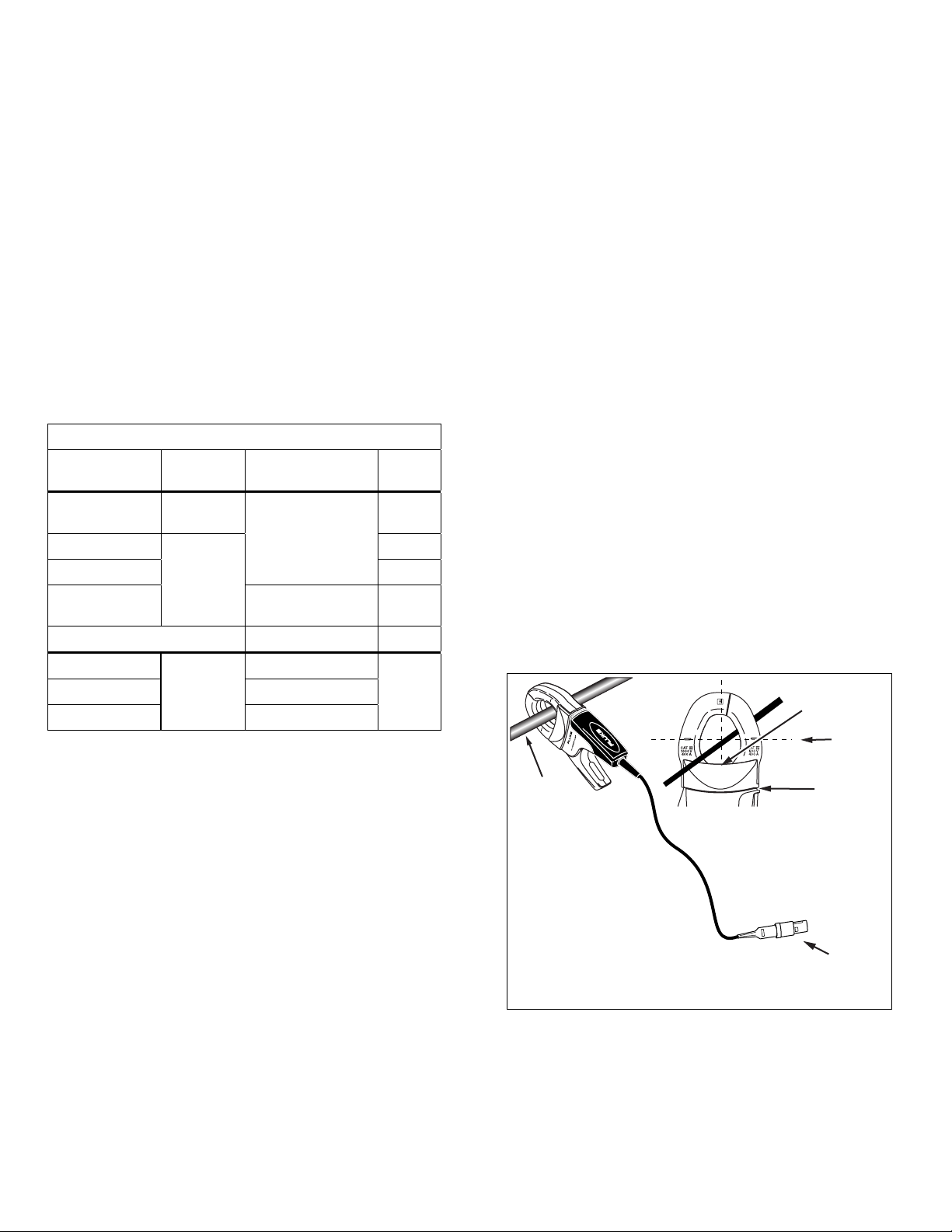
Measurement Considerations
Observe the following guidelines when making measurements,
refer to Figure 1:
• Center the conductor inside the Current Clamp jaw.
• Make sure the clamp is perpendicular to the conductor.
• For optimal reading, make sure the conductor is positioned
between the alignment marks on the jaws of the Current
Clamp.
• Avoid taking measurements close to other current-carrying
conductors.
Operation
To use the Current Clamp:
1. Connect the clamp cable to the measurement
2. Make sure the measurement instrument is set to the
3. Connect the current clamp jaws around the conductor
instrument’s current inputs.
proper range.
to be measured.
XW Warning
To avoid shock or personal injury, keep fingers
behind the tactile barrier, see Figure 1.
Load Direction Arrow
Single Current
Carrying
Conductor
Alignment
Marks
Tactile Barrier
Connector
Figure 1.3140R Setup
bbu01.eps
 Loading...