

Page 1

Hart Scientific
http://www.rongqe.cn/
3125
Detachable Hot Plate
Users’ Manual
Rev. 622101
Page 2

Limited Warranty & Limitation of Liability
Each product from Fluke's Hart Scientific Division ("Hart") is warranted to be free from defects in mate
rial and workmanship under normal use and service. The warranty period is one year for the Surface Cal
ibrator. The warranty period begins on the date of the shipment. Parts, product repairs, and services are
warranted for 90 days. The warranty extends only to the original buyer or end-user customer of a Hart
authorized reseller, and does not apply to fuses, disposable batteries or to any other product which, in
Hart's opinion, has been misused, altered, neglected, or damaged by accident or abnormal conditions of
operation or handling. Hart warrants that software will operate substantially in accordance with its func
tional specifications for 90 days and that it has been properly recorded on non-defective media. Hart does
not warrant that software will be error free or operate without interruption. Hart does not warrant calibra
tions on the Surface Calibrator.
Hart authorized resellers shall extend this warranty on new and unused products to end-user customers
only but have no authority to extend a greater or different warranty on behalf of Hart. Warranty support is
available if product is purchased through a Hart authorized sales outlet or Buyer has paid the applicable
international price. Hart reserves the right to invoice Buyer for importation costs of repairs/replacement
parts when product purchased in one country is submitted for repair in another country.
Hart's warranty obligation is limited, at Hart's option, to refund of the purchase price, free of charge re
pair, or replacement of a defective product which is returned to a Hart authorized service center within
the warranty period.
To obtain warranty service, contact your nearest Hart authorized service center or send the product, with
a description of the difficulty, postage, and insurance prepaid (FOB Destination), to the nearest Hart authorized service center. Hart assumes no risk for damage in transit. Following warranty repair, the product will be returned to Buyer, transportation prepaid (FOB Destination). If Hart determines that the
failure was caused by misuse, alteration, accident or abnormal condition or operation or handling, Hart
will provide an estimate or repair costs and obtain authorization before commencing the work. Following
repair, the product will be returned to the Buyer transportation prepaid and the Buyer will be billed for
the repair and return transportation charges (FOB Shipping Point).
-
-
-
-
-
Rev. 622101
THIS WARRANTY IS BUYER'S SOLE AND EXCLUSIVE REMEDY AND IS IN LIEU OF ALL
OTHER WARRANTIES, EXPRESS OR IMPLIED, INCLUDING BUT NOT LIMITED TO ANY IM
PLIED WARRANTY OF MERCHANTABILITY OR FITNESS FOR A PARTICULAR PURPOSE.
HART SHALL NOT BE LIABLE FOR ANY SPECIAL, INDIRECT, INCIDENTAL. OR CONSE
QUENTIAL DAMAGES OR LOSSES, INCLUDING LOSS OF DATA, WHETHER ARISING FROM
BREACH OF WARRANTY OR BASED ON CONTRACT, TORT, RELIANCE OR ANY OTHER
THEORY.
Since some countries or states do not allow limitation of the term of an implied warranty, or exclusion or
limitation of incidental or consequential damages, the limitations and exclusions of this warranty may not
apply to every buyer. If any provision of this Warranty is held invalid or unenforceable by a court of com
petent jurisdiction, such holding will not affect the validity or enforceability of any other provision.
Fluke Corporation, Hart Scientific Division
799 E. Utah Valley Drive • American Fork, UT 84003-9775 • USA
Phone: +1.801.763.1600 • Telefax: +1.801.763.1010
E-mail: support@hartscientific.com
www.hartscientific.com
Subject to change without notice. • Copyright © 2006 • Printed in USA
-
-
-
Page 3

Table of Contents
1 Before You Start . . . . . . . . . . . . . . . . . . . . . . . . . . 1
1.1 Symbols Used . . . . . . . . . . . . . . . . . . . . . . . . . . . . 1
1.2 Safety Information . . . . . . . . . . . . . . . . . . . . . . . . . . 2
1.2.1 Warnings . . . . . . . . . . . . . . . . . . . . . . . . . . . . . . . . . . . . . 2
1.2.2 Cautions . . . . . . . . . . . . . . . . . . . . . . . . . . . . . . . . . . . . . 4
1.3 Authorized Service Centers. . . . . . . . . . . . . . . . . . . . . . 4
2 Introduction . . . . . . . . . . . . . . . . . . . . . . . . . . . . 7
3 Specifications and Environmental Conditions . . . . . . . . . . 9
3.1 Specifications . . . . . . . . . . . . . . . . . . . . . . . . . . . . . 9
3.2 Environmental Conditions . . . . . . . . . . . . . . . . . . . . . . 9
4 Troubleshooting. . . . . . . . . . . . . . . . . . . . . . . . . . 11
4.1 Troubleshooting Problems, Possible Causes, and Solutions . . . . 11
4.2 Comments . . . . . . . . . . . . . . . . . . . . . . . . . . . . . . 12
4.2.1 EMC Directive . . . . . . . . . . . . . . . . . . . . . . . . . . . . . . . . . 12
4.2.2 Low Voltage Directive (Safety) . . . . . . . . . . . . . . . . . . . . . . . . . 12
i
Page 4

Page 5
1 Before You Start
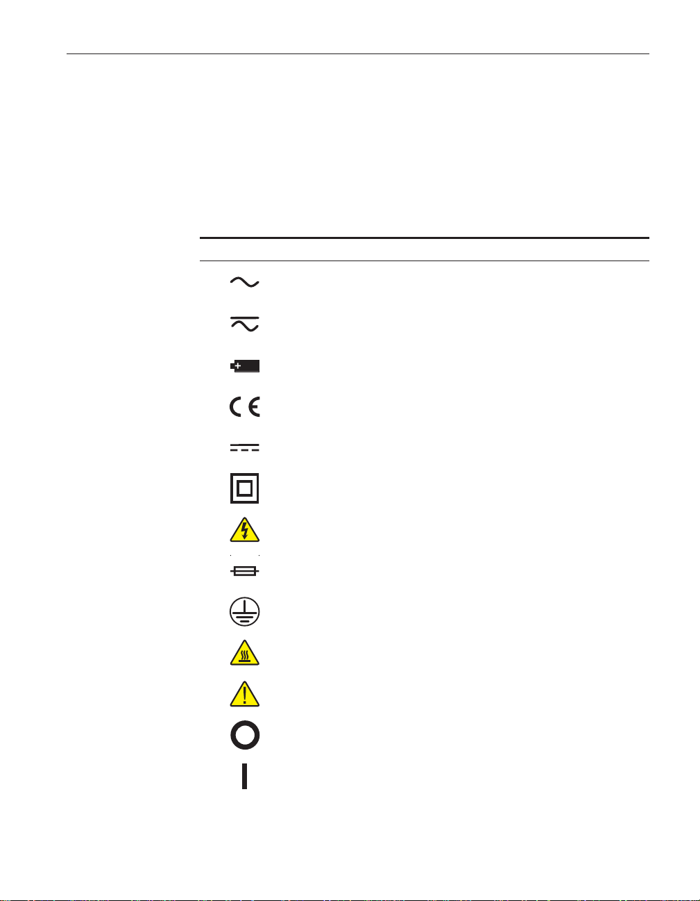
1.1 Symbols Used
Table 1 lists the International Electrical Symbols. Some or all of these symbols
may be used on the instrument or in this manual.
Table 1 International Electrical Symbols
Symbol Description
AC (Alternating Current)
AC-DC
Battery
CE Complies with European Union Directives
1 Before You Start
Symbols Used
DC
Double Insulated
Electric Shock
Fuse
PE Ground
Hot Surface (Burn Hazard)
Read the User’s Manual (Important Information)
Off
On
1
Page 6

3125 Detachable Hotplate
User’s Guide
Symbol Description
Canadian Standards Association
OVERVOLTAGE (Installation) CATEGORY II, Pollution Degree 2 per IEC1010-1 re
fers to the level of Impulse Withstand Voltage protection provided. Equipment of
OVERVOLTAGE CATEGORY II is energy-consuming equipment to be supplied from
the fixed installation. Examples include household, office, and laboratory appliances.
C-TIC Australian EMC Mark
The European Waste Electrical and Electronic Equipment (WEEE) Directive
(2002/96/EC) mark.
1.2 Safety Information
Use this instrument only as specified in this manual. Otherwise, the protection
provided by the instrument may be impaired.
The following definitions apply to the terms “Warning” and “Caution”.
• “Warning” identifies conditions and actions that may pose hazards to the
user.
• “Caution” identifies conditions and actions that may damage the instrument being used.
1.2.1
Warnings
To avoid personal injury, follow these guidelines.
•
BURN HAZARD – DO NOT touch the plate or surrounding areas of the
unit.The temperature of the plate surface is the same as the actual temper
ature shown on the display. If the unit is set at 400°C and the display
reads 400°C, the target surface is 400°C.The top sheet metal of the instru
ment may exhibit extreme temperatures. DO NOT turn off the unit at
temperatures higher than 100°C. This could create a hazardous situation.
Select a set-point less than 100°C and allow the unit to cool before turn
ing it off.
•
DO NOT operate this unit without a properly grounded, properly polar
ized power cord.
•
DO NOT connect this unit to any other instrument or outlet other than the
2200 controller.
•
DO NOT connect the 2200 to a non-grounded, non-polarized outlet.
•
The 2200 Controller and the 3125 Detachable Hot Plate are a matched
set. DO NOT mix and match sets.
•
HIGH VOLTAGE is used in the operation of this equipment. SEVERE
INJURY OR DEATH may result if personnel fail to observe safety pre
-
-
-
-
-
-
2
Page 7

1 Before You Start
Safety Information
cautions. Before working inside the equipment, turn the power off and
disconnect the power cord.
Always replace the fuse with one of the same rating, voltage, and type.
•
This instrument is intended for indoor use only.
•
Overhead clearance is required. DO NOT place this instrument under a
•
cabinet or other structure.
DO NOT use this unit for any application other than calibration work.
•
DO NOT use this unit in environments other than those listed in the
•
user’s guide.
DO NOT operate near flammable materials.
•
Use of this instrument at HIGH TEMPERATURES for extended periods
•
of time requires caution.
Completely unattended high temperature operation is not recommended
•
for safety reasons.
• If this equipment is used in a manner not specified by the manufacturer,
the protection provided by the equipment may be impaired.
• Before initial use, or after transport, or after storage in humid or semi-hu-
mid environments, or anytime the instrument has not been energized for
more than 10 days, the instrument needs to be energized for a "dry-out"
period of 2 hours before it can be assumed to meet all of the safety requirements of the IEC 1010-1. If the product is wet or has been in a wet
environment, take necessary measures to remove moisture prior to applying power such as storage in a low humidity temperature chamber
operating at 50°C for 4 hours or more.
• The instrument generates extreme temperatures. Precautions must be
taken to prevent personal injury or damage to objects. Sensors may be ex
tremely hot when removed from the instrument. Cautiously handle sen
sors to prevent personal injury. Carefully place sensors on a heat resistant
surface or rack until they are at room temperature. Allow the surface to
cool before transporting the instrument.
•
Use only a grounded AC mains supply of the appropriate voltage to
power the instrument. Refer to Section 3.1, Specifications for power de
-
tails.
•
The instrument is equipped with operator accessible system fuses. If a
fuse blows, it may be due to a power surge or failure of a component. Re
place the fuse once. If the fuse blows a second time, it is likely caused by
failure of a component part. If this occurs, contact an Authorized Hart
Scientific Service Center (see Section 1.3). Always replace the fuse with
one of the same rating, voltage, and type. Never replace the fuse with one
of a higher current rating.
•
Follow all safety guidelines listed in the user’s manual.
•
Calibration Equipment should only be used by Trained Personnel.
-
-
3
Page 8

3125 Detachable Hotplate
User’s Guide
1.2.2
Cautions
DO NOT plug the unit into 230V if the heater switches and fuse holder
•
read 115V. This action will cause the fuses to blow and may damage the
instrument.
Components and heater lifetime can be shortened by continuous high
•
temperature operation.
DO NOT change the values of the calibration constants from the factory
•
set values. The correct setting of these parameters is important to the
safety and proper operation of the calibrator.
DO use a ground fault interrupt device.
•
Operate the instrument in room temperatures between 5 and 50°C.
•
(41–122° F). Allow sufficient air circulation by leaving at least 6 inches
of space between the instrument and nearby objects.
Never introduce any foreign material onto the surface plate. Fluids, etc.
•
can leak into the instrument causing damage.
• The instrument is a precision instrument. Although is has been designed
for optimum durability and trouble free operation, it must be handled with
care. Always carry the unit in an upright position. The instrument should
not be operated in excessively wet, oily, dusty, or dirty environments. Do
not operate near flammable materials.
• If a main supply power fluctuation occurs, immediately turn off the instrument. Wait until the power has stabilized before re-energizing the instrument.
1.3 Authorized Service Centers
Please contact one of the following authorized Service Centers to coordinate
service on your Hart product:
Fluke Corporation, Hart Scientific Division
799 E. Utah Valley Drive
American Fork, UT 84003-9775
USA
Phone: +1.801.763.1600
Telefax: +1.801.763.1010
E-mail: support@hartscientific.com
Fluke Nederland B.V.
Customer Support Services
Science Park Eindhoven 5108
5692 EC Son
4
Page 9

NETHERLANDS
Phone: +31-402-675300
Telefax: +31-402-675321
E-mail: ServiceDesk@fluke.nl
Fluke Int'l Corporation
Service Center - Instrimpex
Room 2301 Sciteck Tower
22 Jianguomenwai Dajie
Chao Yang District
Beijing 100004, PRC
CHINA
Phone: +86-10-6-512-3436
Telefax: +86-10-6-512-3437
E-mail: xingye.han@fluke.com.cn
1 Before You Start
Authorized Service Centers
Fluke South East Asia Pte Ltd.
Fluke ASEAN Regional Office
Service Center
60 Alexandra Terrace #03-16
The Comtech (Lobby D)
118502
SINGAPORE
Phone: +65 6799-5588
Telefax: +65 6799-5588
E-mail: antng@singa.fluke.com
When contacting these Service Centers for support, please have the following
information available:
•
Model Number
•
Serial Number
•
Voltage
•
Complete description of the problem
5
Page 10

Page 11

2 Introduction
2 Introduction
Hart Scientific’s Model 3125 Detachable Hot Plate is controlled by Hart Scien
tific’s 2200 controller and uses a precision platinum RTD as a sensor with a
heater to control the temperature. The 3125 and 2200 are a matched set.
The controller display shows the temperature and also the set-point tempera
ture. The temperature may be set to any temperature within the range of 35°C
to 400°C in 0.01°C or °F increments by using the buttons on the control panel.
The controller’s multiple fault protection devices insure user and instrument
safety and protection.
The Detachable Hot Plate (see Figure 1) consists of a controlled plate made of
aluminum. A heater is attached to the bottom with an RTD temperature sensor
used to control it. The housing consists of a top cover and a base, which serve
as a clamp and strain relief point for the wiring. The Reference Well is avail
able for use with a 3/16-inch diameter probe, which may be used to check the
plate temperature. This well is used to calibrate the system.
1150/2300 W
10 A
115/230 V
50/60 Hz
115V
1
HEATER
3
PROBE
2
4
RS-232
-
115/230 VAC 50/60 Hz
2200 Controller Back Panel
3125 Hot Plate Assembly
Figure 1 Controller and Hotplate Assembly
7
Page 12

Page 13

3 Specifications and Environmental
Conditions
3.1 Specifications
Temperature Range 35°C to 400°C (95°F to 752°F)
Display Accuracy ±0.5°C to 200°C
Stability ±0.2°C to 300°C
Resolution 0.01°
Uniformity ±0.3°C at 100°C
Heating Time
Cooling Time
Stabilization Time 8 minutes
Controller Model 2200 Microprocessor based with RS-232 serial port
Readout °C or °F switchable
Sensor
Heater 325 Watt, solid state controlled
Surface Plate 6061 aluminum; top surface machine finished to 0.000032" (0.0008 mm), 3.8" (96
Power 115 VAC (±10%), 2.8 A or 230 VAC (±10%), 1.4 A, specify, 50/60 Hz, 325 W
Weight 7 lb. (3.2 kg) with 2200 Controller
NIST-Traceable
Calibration
Safety OVERVOLTAGE (Installation) CATEGORY II, Pollution Degree 2 per IEC1010-1
±1.0°C to 400°C
±0.3°C to 400°C
±0.6°C at 200°C
±0.9°C at 300°C
±1.4°C at 400°C
°
C to 400°C: 22 minutes
25
°
C to 100°C: 65 minutes
400
Ω
RTD, 100
mm) diameter accessible
Data at 50°C, 120°C, 190°C, 260°C, 330°C, and 400°C
3.2 Environmental Conditions
Although the instrument has been designed for optimum durability and trou
ble-free operation, it must be handled with care. The instrument should not be
operated in an excessively dusty or dirty environment. The instrument operates
safely under the following conditions:
•
temperature range: 5-40°C (41-104°F)
-
9
Page 14

ambient relative humidity: maximum 80% for temperature <31°C, de
•
creasing linearly to 50% at 40°C
pressure: 75kPa-106kPa
•
mains voltage within ±10% of nominal
•
vibrations in the calibration environment should be minimized
•
altitude does not effect the performance or safety of the unit
•
-
10
Page 15

4 Troubleshooting
4 Troubleshooting
4.1 Troubleshooting Problems, Possible Causes,
and Solutions
In the event that the instrument appears to function abnormally, this section
may help to find and solve the problem. Several possible problem conditions
are described along with likely causes and solutions. If a problem arises, please
read this section carefully and attempt to understand and solve the problem. If
the problem cannot otherwise be solved, contact an Authorized Service Center
(see Section 1.3). Be sure to have the model number, serial number, and voltage
of your instrument available.
Problem Possible Causes and Solutions
Incorrect temperature
reading
Incorrect R0, ALPHA, and DELTA parameters. Find the values for R0, AL
PHA, and DELTA on the Report of Calibration that was shipped with the instru
ment (or from subsequent calibrations of the instrument). Reprogram the
parameters into the 2200 memory (see the 2200 User’s Guide). Allow the instrument to stabilize and verify the accuracy of the temperature reading.
Controller locked up. The controller may have locked up due to a power
surge or other aberration. Initialize the system by performing the Factory Reset
Sequence.
-
-
Blank display after
mains power applied
The Instrument heats or
cools too quickly or too
slowly
Factory Reset Sequence. Hold the SET and EXIT buttons down at the same
time while powering up the instrument. After the instrument displays
release the buttons. The display shows
displays the firmware version. After performing the master reset sequence, all
of the configuration parameters are reset to their default values. Reprogram the
R0, ALPHA, and DELTA parameters into the Model 9132 memory (see Section
, Calibration Parameters) and any other applicable configuration parameters.
Allow the instrument to stabilize and verify the accuracy of the temperature
reading.
Blown fuse. A fuse may have blown due to a power surge or failure of a com
ponent. Replace the fuse once. If the fuse blows a second time, it is likely
caused by the failure of a component. Always replace the fuse with one of the
same rating, voltage, and type. Never replace the fuse with one of a higher cur
rent rating.
Incorrect scan and scan rate settings. The scan and scan rate settings may
be set to unwanted values. Check the Scan and Scan Rate settings. The scan
may be off (if the unit seems to be responding too quickly). The scan may be
on with the Scan Rate set low (if unit seems to be responding too slowly).
-init-
, then displays
9132
-init-
,
, and then
-
-
11
Page 16

3125 Detachable Hotplate
User’s Guide
Problem Possible Causes and Solutions
The display shows any
of the following:
err 2,err 3,err
4
,
Err 5,Err 6
Err 7
Temperature cannot be
set above a certain point
4.2 Comments
4.2.1 EMC Directive
Hart Scientifics’ equipment has been tested to meet the European Electromagnetic Compatibility Directive (EMC Directive, 89/336/EEC). The Declaration
of Conformity for your instrument lists the specific standards to which the unit
was tested.
err 1
,or
Controller problem. The error messages signify the following problems with
,
the controller.
Err 1
- a RAM error
Err 2
- a NVRAM error
Err 3
- a Structure error
Err 4
- an ADC setup error
Err 5
- an ADC ready error
Err 6
– a defective control sensor
Err 7
– a heater error
Initialize the system by performing the Factory Reset Sequence describe
above.
Incorrect High Limit parameter. The High Limit parameter may be set below
400°C. Check this value as described in the 2200 User’s Guide.
12
4.2.2 Low Voltage Directive (Safety)
In order to comply with the European Low Voltage Directive (73/23/EEC),
Hart Scientific equipment has been designed to meet the IEC 1010-1 (EN
61010-1) and the IEC 1010-2-010 (EN 61010-2-010) standards.
 Loading...