

Page 1
2635A-PRINT 120
2635A-PRINT 230
Serial 80 Column Dot-Matrix Printers
Instruction Sheet
®
Introduction
The 2635A-PRINT 120 and 2635A-PRINT 230 Serial
Printers (hereafter referred to as “the Printer”) are 80Column Dot-Matrix Serial Printers that can be
connected directly to the Fluke Hydra Series (2635A,
2625A, and 2620A models hereafter referred to as
“the Hydra”) to provide printed hard-copy output
without the need for a computer or software. The
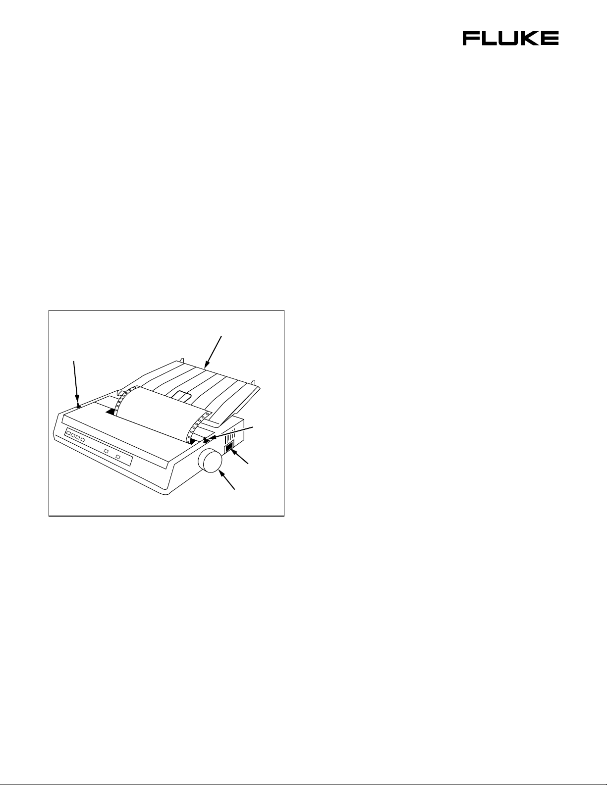
Printer is shown in Figure 1.
Paper Separator
Bail Arm
Lever
Paper
Lever
Power
Switch
Installation
XWWarning
To avoid possible electric shock or
personal injury:
• Verify that the line voltage marked
on the back of the printer matches
the local mains supply before
connection.
• Check that the voltage listed on
the rating plate, located on the
back of the printer, matches the
local mains supply voltage before
applying power.
Some Printer parts have been removed for shipping.
Reassemble its detached parts, as follows (see
Figure 1 and the Quick Setup Guide for details):
1. Install the platen knob on the shaft on the rightside of the Printer, lining up the slot in the knob
with the pin on the shaft.
2. Remove shipping tape from the Printer, and open
the top cover.
Platen Knob
Figure 1. 2635A-PRINT Printer
egv001.eps
Shipping Contents
The Printer comes with the following items:
• Instructions for Printer setup and use (this sheet)
• Quick Start Guide
• Platen knob
• Ribbon cartridge
• Paper separator
• CD-ROM with User’s Guide and print drivers
• Fluke RS42 serial printer cable
PN 2558806 February 2006 ©2006 Fluke Corporation. All rights reserved. Printed in U.S.A. 1
3. The print head is held to one side by a plastic
shipping retainer. Remove the retainer. Save the
retainer in case the Printer ever needs to be
shipped.
4. Center the print head by gently pushing it to the
center of the platen area.
5. Attach the ribbon cartridge to the print head by
setting the front-end in place and carefully
snapping the ribbon down between the print head
and platen.
6. Attach the paper separator by slipping the hooks
on its front into the two slots on the top of the
Printer.
Page 2

2635A-PRINT 120, 2635A-PRINT 230
Instruction Sheet
Loading Printer Paper
XWWarning
If the printer has been recently used,
the print head may still be hot.
To allow continuous printing of Hydra scan data,
Continuous Forms-type paper is recommended.
Load continuous forms paper as follows (see
Figure 1):
1. Set the paper lever (located on the right-side) to
its forward position to select “Continuous
Forms”.
2. Move the bail arm lever (located on the left-side)
forward to release bail arm pressure from the
platen.
3. With the top-cover open, thread the continuous
forms paper either in from the back, under the
paper separator and down behind the platen, or up
through the slot on the bottom of the Printer.
4. Raise the paper in front of the platen to a level
above the Printer top.
5. If the paper has sprocket holes on the sides, adjust
the spacing of the sprockets on the platen to fit the
paper properly. For more details, see the User’s
Guide on the included CD-ROM.
6. With the paper in the correct position on the
platen and sprockets, move the bail arm lever
back to press the bail arm against the paper.
7. Close the top cover, making sure to thread the
paper up through the slot.
8. Using the platen knob, adjust the paper to the
right starting position with the top edge of the
paper above the bail arm.
Connecting the Printer
The Printer connects directly to the Hydra’s RS-232C
connector on the Hydra rear panel, using the supplied
RS42 serial printer cable.
To simplify system setup, Printer default settings
correspond to Hydra series instruments. No
adjustments to these settings are necessary.
To set up the Printer:
1. Connect the larger 25-pin connector end of the
RS42 serial printer cable to the serial interface
connector on the Printer.
2. Connect the 9-pin connector end of the RS42
serial cable to the RS-232C serial connector on
the rear panel of the Hydra.
3. Connect power cord to the rear of the Printer, and
plug it into an appropriate power outlet.
4. Turn the Printer power on.
To set up the Hydra:
1. Check that the Hydra is set to 9600 Baud and No
Parity (refer to the proper Hydra Users Manual
for instructions). Use the
[COMM]
buttons on the Hydra front panel to
SHIFT and LIST
check and set if needed.
2. Set the Hydra for Autoprint mode. See the
instructions below for the appropriate model:
• 2635A Data Bucket
1. Press the
SHIFT and FILES [MODE]
buttons.
2. Select PRINT (or BOTH) Destination
using up or down arrow keys.
3. Press
ENTER.
9. Press the
SELECT button on the front of the
Printer to put it on-line. The light next to the
SELECT button indicates the printer is online.
2
4. Select ALL for the Mode.
5. Press the
ENTER key again.
• 2625A Data Logger
1. Press the
SHIFT and PRINT [MODE]
buttons.
2. Select PRINT (or BOTH) Destination
using up or down arrow keys.
3. Press
ENTER.
4. Select ALL for the Mode.
5. Press the
6. Check that the
ENTER key again.
PRN annunciator on the
display is on.
Page 3

Serial 80 Column Dot-Matrix Printers
Operation
7. Press the PRINT button on the Hydra if
necessary to turn
PRN on.
• 2620A Data Acquisition Unit
1. Check that the
PRN annunciator on the
display is on.
2. Press the
necessary to turn
PRINT button on the Hydra if
PRN on.
Operation
Before starting Scan on the Hydra, ensure that the
Printer is set up and paper is loaded. Also check that
the Hydra is set to Autoprint mode as described
above. Press the
Printer if necessary to put it on-line.
Press the
SCAN button on the Hydra to start scanning.
The Printer should print each scan as it occurs. Press
SCAN again to stop scanning.
The Printer has been set to operate in its
default factory setting as an accessory to the
Hydra. Please refer to the manufacturer’s
instructions and supplied software for
operating the Printer in other applications.
Refer to the included CD-ROM for other
applications.
SELECT button on the front of the
Note
Paper
Type Feed Weight Width
Cut Sheets Top only
Continuous,
Single Part
Continuous,
Multipart
• 4 sheets
(orig.+3),
Carbonless
• Up to 0.11"
(0.28 mm)
Rear/
Bottom
Rear/
Bottom
16 to 21 lb.
US Bond
(60 to 81 g/m²)
14 to 20 lb.
US Bond
(53 to 75 g/m²)
14 to 20 lb.
US Bond
(53 to 75 g/m²)
3 in to 9.5 in
(76 to 241 mm)
3 in to 9.9 in
(76 to 251 mm)
3 in to 9.9 in
(76 to 251 mm)
Reliability
Ribbon Life 3 million characters (avg.)
Print head Life 200 million characters average in
10 cpi utility mode
Mean Time
Between
20,000 hours at 25 % duty cycle
and 35 % page density
Failures
(MTBF)
Specifications
General
Print Method Impact dot matrix
Print head
Emulations
(co-resident)
Print Speed,
characters per
second (cps)
Buffer size 128 Kb
9 pins, 0.0118 in (0.30 mm)
diameter, with thermal protection
IBM 2480
Epson ESC/P2
Okidata MICROLINE Standard
Super Speed
Draft (SSD)
High Speed
Draft (HSD)
Utility (UTL) 250 cps
Near Letter
Quality (NLQ)
375 cps
(12 cpi only)
333 cps
62.5 cps
Physical
Height 3.15 in (80 mm)
Width 14.65 in (372 mm)
Depth 10.83 in (275 mm)
Weight 9.9 lb (4.5 Kg)
Electrical
Voltage 120 V, +6 %, -15 %
(2635A-PRINT 120 model)
230 V, +15 %, -14 %
(2635A-PRINT 230 model)
Frequency 50 or 60 Hz, ±2 %
3
Page 4

2635A-PRINT 120, 2635A-PRINT 230
Instruction Sheet
Environmental
Temperature
Operating
Storage
Humidity
Operating
Storage
Noise level
Normal:
Quiet Mode:
41 to 104 °F (5 to 40 °C)
-40 to 158 °F (-40 to +70 °C)
20 to 80 % RH
5 to 95 % RH
Less than 54 dBA
Less than 51 dBA
Interfaces
Serial Models RS-232C Serial
USB 1.1
Contacting Fluke
To locate an authorized service center, visit us on the
World Wide Web at www.fluke.com
using any of the following numbers:
USA: 1-888-99-FLUKE (1-888-993-5853)
Canada: 1-800-36-FLUKE (1-800-363-5853)
Europe: +31 402-675-200
Japan: +81-3-3434-0181
Singapore: +65-738-5655
Anywhere in the world: +1-425-446-5500
LIMITED WARRANTY AND LIMITATION OF LIABILITY
This Fluke product will be free from defects in material and
workmanship for 90 days from the date of purchase. This warranty
does not cover fuses, disposable batteries, or damage from
accident, neglect, misuse, alteration, contamination, or abnormal
conditions of operation or handling. Resellers are not authorized to
extend any other warranty on Fluke’s behalf. To obtain service
during the warranty period, contact your nearest Fluke authorized
service center to obtain return authorization information,
then send the product to that Service Center with a description of
the problem.
THIS WARRANTY IS YOUR ONLY REMEDY. NO OTHER WARRANTIES,
SUCH AS FITNESS FOR A PARTICULAR PURPOSE, ARE EXPRESSED
OR IMPLIED. FLUKE IS NOT LIABLE FOR ANY SPECIAL, INDIRECT,
INCIDENTAL OR CONSEQUENTIAL DAMAGES OR LOSSES, ARISING
FROM ANY CAUSE OR THEORY.
Since some states or countries do not allow the exclusion or
limitation of an implied warranty or of incidental or consequential
damages, this limitation of liability may not apply to you.
Fluke Corporation
P.O. Box 9090
Everett, WA 98206-9090
U.S.A.
11/99
Fluke Europe B.V.
P.O. Box 1186
5602 BD Eindhoven
The Netherlands
or call Fluke
4
 Loading...