

Page 1
300V
MAX
COM
V
FUNC ALRM
Mx+B
CANCEL
ENTER
RATE
INTVL PRINT REVIEW
SHIFT LIST TOTAL
SINGLE
TRIGS
SCAN
MON
CLOCK MODE CLEAR
LOCAL COMM ZERO
POWER
HYDRA
m
A
m
V
D
C
A
C
k
H
z
R
E
V
I
E
W
L
A
S
T
M
C
H
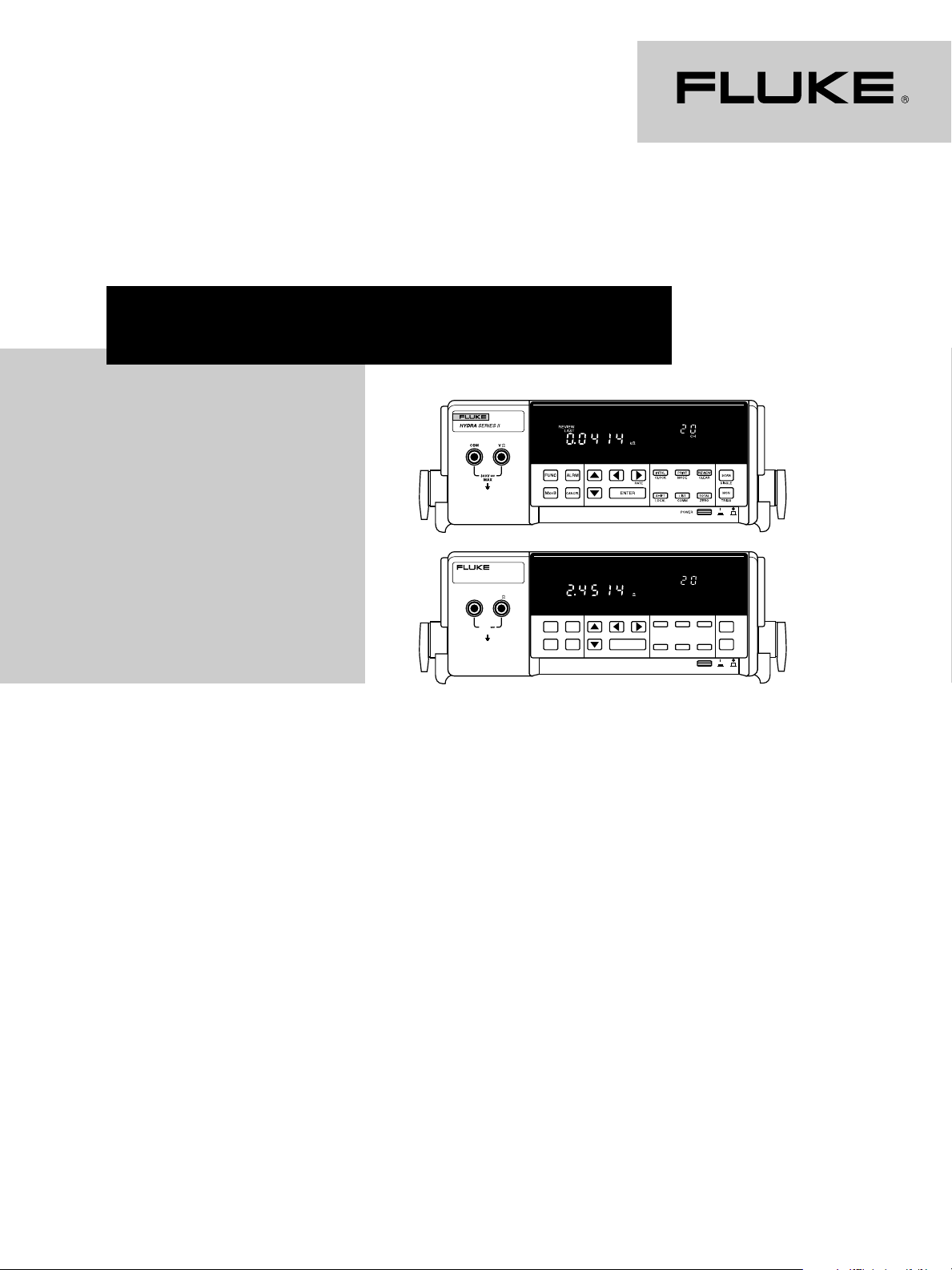
DATA ACQUISITION UNIT
Data Acquisition
Detailed Specifications
2680A Series - NetDAQ® - Hydra Series
Models 2620A, 2620A/05, 2625A, 2635A
This document provides detailed
specifications for the Fluke
2680A Series, Hydra Series and
NetDAQ data acquisition products.
This is a supplement to the Fluke
Data Acquisition Tools brochure
(1267610). If you wish to
obtain a copy of this product
brochure you may call: in the
U.S.A., (800) 44-FLUKE; Canada,
(905) 890-7600; Europe, +31
(0) 40 2 678 200; other countries,
(425) 356-5116, or contact your
local representative.
Hydra Series
Hydra Series
Channel capacity
Analog inputs: 21
Digital I/0 and alarm outputs:
12 total
Totalizer: 1
Power
90 to 264 Vac, 50 or 60 Hz
(<10W), or 9 to 16 Vdc (<4W)
(If both sources are applied
simultaneously, the greater of
ac or dc is used.) At 120 VAC the
equivalent DC voltage ~14.5V.
Temperature, humidity
(non-condensing)
Operating: 0°C to 28°C, ≤ 90%
RH;
28°C to 40°C,≤ 75% RH;
40°C to 60°C, ≤ 50% RH
Storage: -40°C to 75°C, 5% to
95% RH
Altitude
Operating: 2000 m
Storage: 12000 m
Voltage ratings
300 Vdc or Vac rms (channels
0,1,11); 150 Vdc or Vac rms (all
other inputs) IEC Overvoltage
Category II
Common mode voltage
300V dc or ac rms maximum
from any analog input (channel)
to earth provided that channel
to channel maximum voltage
ratings are observed
Standards
IEC1010, ANSI/ISA-S82.01-1994,
CSA-C22.2 No. 1010.1-92, and
EN61010-1:1993. Complies with
EN 50081-1, EN 50082-1, Vfg.
243/1991 and FCC-15B at the
Class B level, when shielded
cables are used.
Size
9.3 cm H x 21.6 cm
W x
31.2 cm D
Weight
3.0 kg
Interfaces
RS-232
connector: Nine pin male
(DB-9P)
signals: TX, RX, DTR, GND,
CTS,* DSR,* RTS*
modem
control: Full duplex
baud rate: 300, 600, 1200,
2400, 4800,
9600, 19.2k*,
38.4k*
data format: 8 data bits, no
parity, one stop
bit; or 7 data bits,
one parity bit, one
stop bit
parity: Odd, even, none
echo: On/Off
flow control: XON/XOFF, CTS*
* 2635A only
IEEE-488 (Optional, 2620A only)
Disables RS-232 interface while
in use.
Memory life
10 years minimum for real time
clock, setup configuration and
measurement data (from date of
manufacture)
Page 2
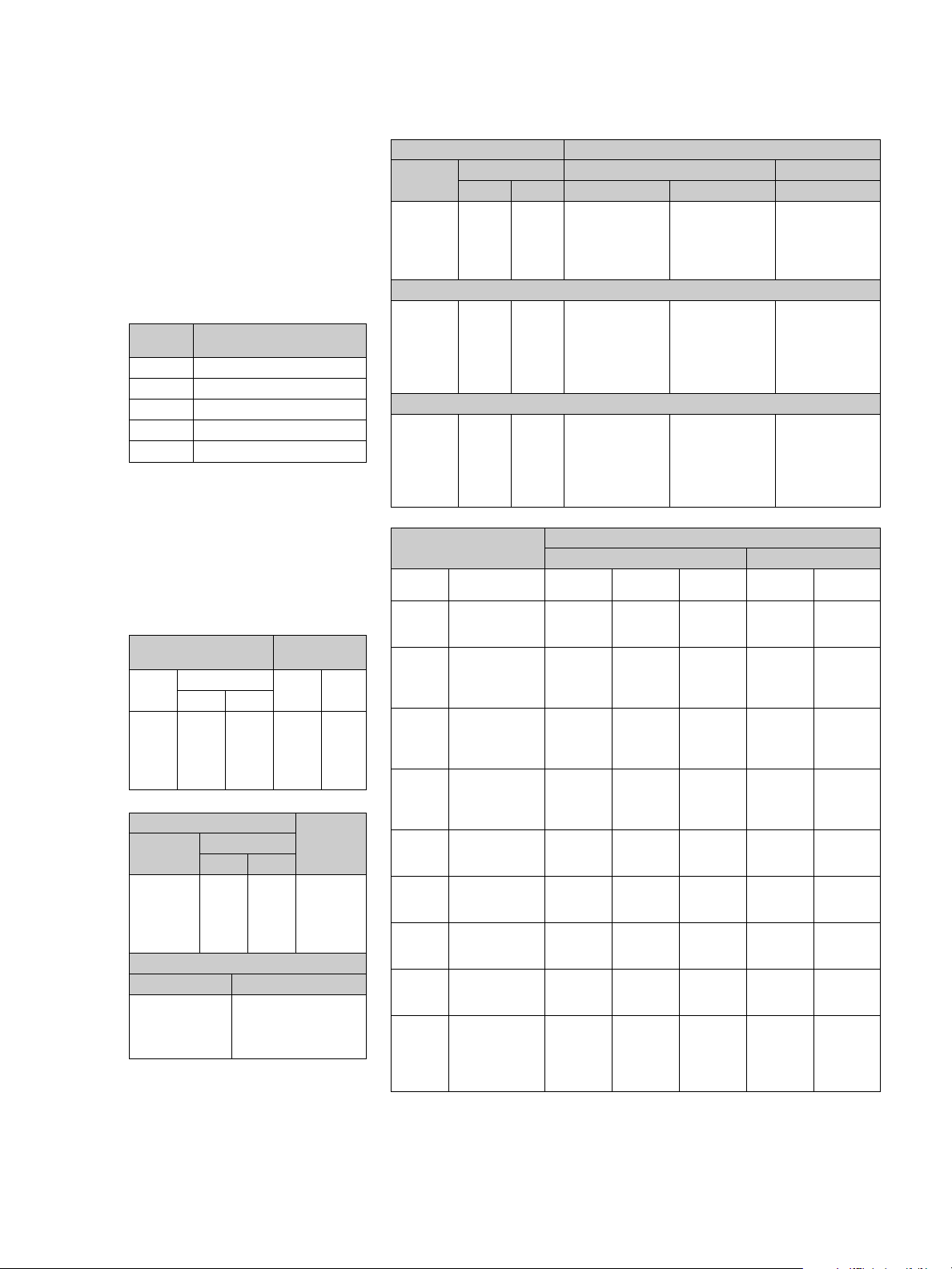
2635A memory card
Type: SRAM type only; PCMCIA
compliant
Capacity: The chart below shows
Memory Card storage capacity in
scans for one data file. One scan
comprises date and time, readings from all defined analog input
channels, the status of the four
alarm outputs and eight digital
I/O, and the totalizer count.
Number of scans per card
Memory Channels in scan
Card size 4 10 20
256 kb 8900 4800 2710
512 kb 18250 9840 5560
1 Mb 36860 19860 11210
2 Mb 74110 39910 22550
4 Mb 149039 80251 45359
2625A data memory
Stores 2,047 scans
•
Stored with each scan: time
•
stamp, all defined analog input
channels, the staus of four
alarm outputs and eight digital
I/O, and the totalizer count
Memory life: 5 years minimum;
•
at 25°C
RTD (Pt 100)
Temp.
(°C) Slow Fast Slow Fast
-200°C 0.02 0.1 0.05 0.47
0°C 0.02 0.1 0.09 0.55
100°C 0.02 0.1 0.10 0.58
300°C 0.02 0.1 0.14 0.65
600°C 0.02 0.1 0.20 0.76
Range Slow Fast
15-900 Hz 0.01 Hz 0.1 Hz 0.05 + 2
9 kHz 0.1 Hz 1.0 Hz 0.05 + 1
90 kHz 1 Hz 10 Hz 0.05 + 1
900 kHz 10 Hz 100 Hz 0.05 + 1
1 MHz 100 Hz 1 kHz 0.05 + 1
15 Hz-100 kHz 100 mV rms sine wave
100 kHz-300 kHz 150 mV rms sine wave
300 kHz-1 MHz 2V rms sine wave
Above 1 MHz not specified
Resolution
Frequency
Resolution
Sensitivity
Frequency Level
Accuracy
1,3
±°C
(4-Wire)
Accuracy
(Slow/Fast)
± (%+counts)
Measurement accuracy
1,4
, 3
σσ
σ, ±(%+V)
σσ
1,3
±(%+Ω)
1,2
σσ
σ, (± °C)
σσ
±(%+counts)
DC Voltage Accuracy1, 3
Range
90 mV* 1 µV10 µV.019% + 6 µV .024% + 6 µV .044% + 20 µV
300 mV 10 µV100 µV.018% + 20 µV .023% + 20 µV .040% + 0.2 mV
3V 100 µV1 mV .019% + 0.2 mV .024% + 0.2 mV .041% + 2 mV
30V 1 mV 10 mV .019% + 2 mV .024% + 2 mV .041% + 20 mV
300/150V 10 mV 100 mV .019% + 20 mV .024% + 20 mV .041% + 0.2V
Resistance Accuracy (4-wire)
300Ω 10 mΩ 100 mΩ 0.013% + 20 mΩ 0.014% + 20 mΩ 0.014% + 200 mΩ
3 kΩ 100 mΩ 1Ω 0.015% + 0.2Ω 0.016% + 0.2Ω 0.016% + 2Ω
30 kΩ 1Ω 10 Ω 0.013% + 2Ω 0.014% + 2Ω 0.014% + 20Ω
300 kΩ 10Ω 10 0Ω 0.020% + 20Ω 0.021% + 20Ω 0.021% + 0.2 kΩ
3 MΩ 10 0Ω 1 kΩ 0.059% + 0.2 kΩ 0.063% + 0.2 kΩ 0.063% + 2 kΩ
10 MΩ 1 kΩ 10 kΩ 0.168% + 2 kΩ 0.169% + 2 kΩ 0.709% + 20 kΩ
AC Voltage (True rms, ac coupled) Frequency Accuracy
300 mV 10 µV100 µV 50 Hz-150 Hz 0.3% + 15 0.3% + 4
3V 100 µV1 mV 150 Hz-10 kHz 0.16% + 15 0.16% + 4
30V 1 mV 10 mV 10 kHz-20 kHz 0.37% + 15 0.37% + 4
300/150V 10 mV 100 mV 20 kHz-50 kHz 1.9% + 20 1.9% + 4
Thermocouples
2635A ITS90 18 to 28°C0 to 60°C
Type Temp. (°C)
J -30°C to 150°C 0.37 0.39 0.80 0.57 1.02
K -25°C to 120°C 0.43 0.44 0.93 0.62 1.16
N -25°C to 120°C 0.53 0.55 1.22 0.67 1.39
E -25°C to 350°C 0.38 0.39 0.77 0.61 0.98
T0°C to 120°C 0.45 0.46 0.95 0.59 1.13
R 400°C to 1000°C 0.79 0.81 2.30 1.15 2.53
S1000°C to 1400°C 0.83 0.89 2.34 1.47 2.94
B1200°C to 1550°C 0.74 0.77 2.25 1.18 2.57
C 650°C to 1000°C 0.70 0.76 1.81 1.29 2.38
*2635A only
Note: The terms “slow” and “fast” in these tables refer to the minimum and maximum measurement
speed (Rdgs/s) as listed in the specifications for a specific model.
Resolution Slow Fast
Slow Fast 90 days 1 year 1 year
20 Hz-50 Hz 1.43% + 15 1.43% + 4
50 kHz-100 kHz 5.0% + 50 5.0% + 10
5
90 days 1 year 1 year 1 year 1 year
slow slow fast slow fast
-100°C to -30°C 0.42 0.43 0.91 0.55 1.08
150°C to 760°C 0.44 0.48 0.94 0.88 1.38
-100°C to -25°C 0.52 0.53 1.13 0.65 1.31
120°C to 1000°C 0.61 0.68 1.38 1.28 2.03
1000°C to 1372°C 0.89 0.98 1.87 1.85 2.79
-100°C to -25°C 0.62 0.63 1.44 0.75 1.61
120°C to 410°C 0.47 0.49 1.08 0.69 1.28
410°C to 1300°C 0.70 0.78 1.52 1.45 2.23
-100°C to -25°C 0.44 0.46 0.91 0.57 1.09
350°C to 650°C 0.39 0.43 0.82 0.80 1.23
650°C to 1000°C 0.50 0.56 1.05 1.11 1.63
-150°C to 0°C 0.68 0.69 1.50 0.82 1.71
120°C to 400°C 0.36 0.39 0.78 0.61 1.02
250°C to 400°C 0.83 0.85 2.47 1.02 2.66
1000°C to 1767°C 0.96 1.05 2.59 1.85 3.42
250°C to 1000°C 0.88 0.89 2.60 1.26 2.80
1400°C to 1767°C1.07 1.17 2.96 2.03 3.84
600°C to 1200°C1.111.12 3.53 1.27 3.69
1550°C to 1820°C 0.82 0.89 2.35 1.43 2.90
0°C to 150°C 0.72 0.73 1.90 0.86 2.08
150°C to 650°C 0.62 0.64 1.62 0.99 1.94
1000°C to 1800°C1.121.25 2.86 2.38 4.04
18 00°C to 2316°C1.86 2.08 4.61 4.06 6.66
Accuracy
2 Fluke Corporation Data Acquisition Full Line Specifications
Page 3

Measurement accuracy cont.
Thermocouples
B1200 to 1550 0.74 0.77 2.25 1.18 2.57
C 650 to 1000 0.70 0.76 1.81 1.29 2.38
1000 to 1800 1.12 1.25 2.86 2.38 4.04
1
Total instrument accuracy for 1 year following calibration (unless otherwise stated). Ambient
operating temperature 18°-28°C (unless otherwise stated). Includes A/D errors, linearization
conformity, initial calibration error, isothermality errors, and reference junction conformity.
(Sensor inaccuracies not included.) Relative humidity up to 90% non-condensing (except up
to 70% for the 300 kΩ, 3 MΩ, and 10 MΩ ranges).
2
Sine wave inputs >2000 counts (slow), >200 counts (fast). Accuracies for crest factor ≤2.0.
3
DIN/IEC 751 only, 4-wire configurations.
4
Resolution is 0.1°C or 0.1°F over the useful range of base metal thermocouples (J, K, T, E, N) and
0.2° resolution for types R, S, B, and C, with slow scan. Fast scan resolution =1°C or F.
5
Open thermocouple detection is performed on each thermocouple channel unless defeated by
computer command. IPTS 68 specifications are published in the user manual.
5
600 to 1200 1.11 1.12 3.53 1.27 3.69
1550 to 1820 0.82 0.89 2.35 1.43 2.90
0 to 150 0.72 0.73 1.90 0.86 2.08
150 to 650 0.62 0.64 1.62 0.99 1.94
18 00 to 2316 1.86 2.08 4.61 4.06 6.66
Accuracy
18 to 28°C0 to 60°C
1,4
σσ
, 3
σ, (± °C)
σσ
Front panel input
DCV, ACV, (300V maximum)
resistance, frequency. Use any
of the Fluke TL Series of test
leads. (One set of TL70 test
leads included with Hydra)
Common mode rejection
AC: ≥120 dB (50/60 Hz, ± 0.1%
max 1 kΩ source imbalance)
DC: ≥120 dB
Normal mode rejection
53 dB (60 Hz, ± 0.1%)
47 dB (50 Hz, ±0.1%)
Scan speed
Slow: 4 readings/second nominal
Fast: 18 readings/second nomi-
nal
(1.5
readings/sec
ond for ACV
and Ω inputs nominal)
Analog to digital converter
Dual Slope type, linear to 17 bits
Totalizing inputs
DC coupled, non-isolated,
max + 30V, min -4V
Max count: 65,535
Minimum signal: 2V peak
Threshold: 1.4V
Rate: 0-5 kHz (debounce off)
Hysteresis: 500 mV
Input debouncing: None or
1.66 ms
Digital inputs
Threshold: 1.4V
Hysteresis: 500 mV
Maximum input: +30V,
min -4V; non-isolated
Digital/Alarm outputs
The open collector output lines
are non-isolated, TTL compatible with the following logic
levels:
Logical “zero” output:
0.8V max | out = -1.0 mA
(1 LSTTL load equivalent)
1.8V max, | out = -20 mA
3.25V max, | out = -50 mA
Logical “one” output:
Output voltage depends on
external load
3.8V min, | out = 0.05 mA
(1 LSTTL load equivalent)
Trigger input
Minimum pulse: 5 µs
Maximum latency: 100 ms
Repeatability: 1 ms
Input “High”: 2.0V min, 7.0V max
Input “Low”: -0.6V min, 0.8V max
Non-isolated, contact closure
and TTL compatible
Clock
Accurate to within 1 minute/
month for 0°C to 50°C range
Calibration
Calibration is performed closedcase via software, eliminating
troublesome mechanical adjustments. This improves operational reliability by avoiding the
drift caused by vibration, temperature, and humidity on conventional calibration controls.
Alarms associations
Configured
from 0123 0123 4 567
Front panel ch0 ch1 ch2 ch3 digital inputs ch4 ch5 ch6 ch7
Computer ch0 ch1 ch2 ch3
Alarm outputs Digital I/O
(Fixed) ch8 ch9 ch10 ch11
ch12 ch13 ch14 ch15
ch16/20 ch17 ch18 ch19
(Fixed) Each Digital I/O may be randomly assigned as a digital
input, status output, or alarm output (associated with any
input channel or channels), except ch 0-3
Data Acquisition Full Line Specifications Fluke Corporation 3
Page 4
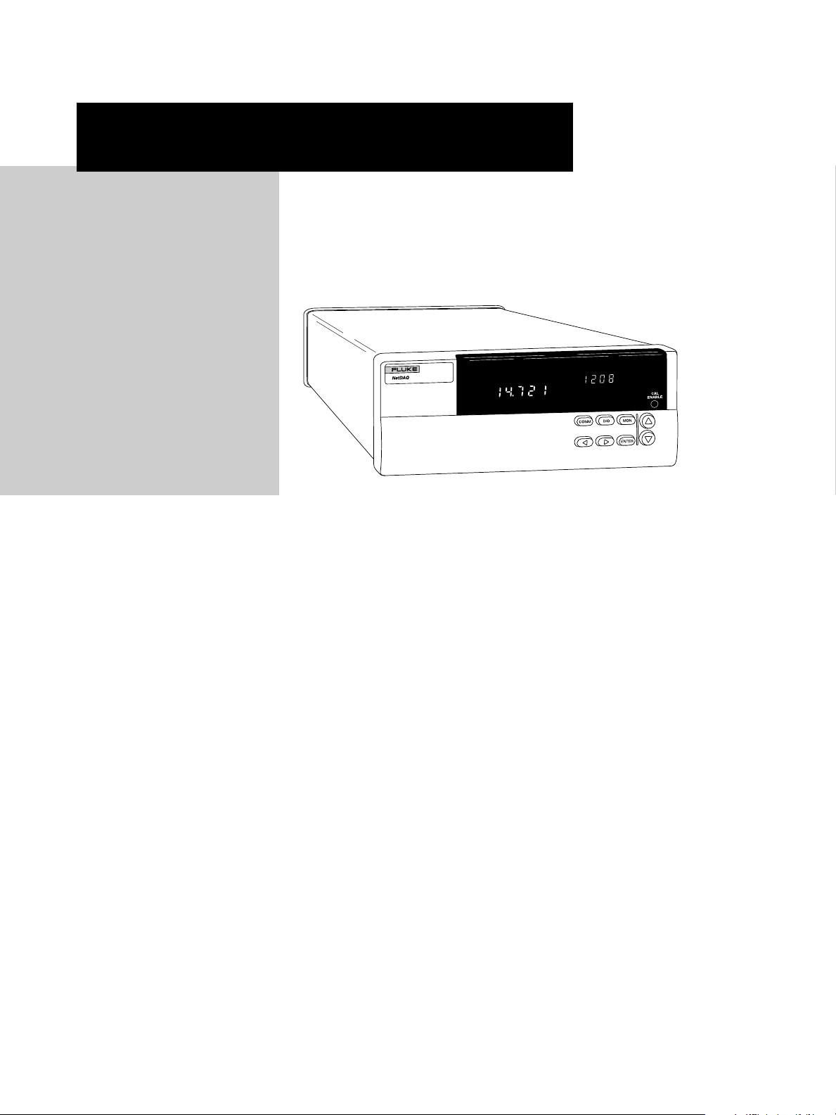
2640A
100, 50, 6 readings/second
•
18 bit A/D resolves 0.3 µV
•
and .02°C
300V maximum measurement
•
input
Built-in signal conditioning
•
Real time on-board clock
•
-20 to 60°C (-4 to 140°F) oper-
•
ating temperature
2645A
1000, 200, 48 readings/second
•
16 bit A/D resolves 3 µV
•
and 0.2°C
50V maximum measurement
•
input
Built-in signal conditioning
•
Real time on-board clock
•
-20 to 60°C (-4 to 140°F)
•
operating temperature
NetDAQ® Series
Models 2640A and 2645A
NetDAQ Series
Channel capacity
Analog inputs: 20
Computed channels: 10
Digital I/O and alarm outputs:
8 total
Totalizer: 1
Math functions
In addition to its 20 analog input
channels, each NetDAQ unit supports 10 computed channels.
Calculations include: addition,
subtraction, multiplication, division, log, natural log, exponent,
square root, absolute value, integer function, and average.
Measurement speed (2640A)
Slow: 6 readings/second nominal
Medium: 41 (50 Hz), 48 (60 Hz)
readings/sec
Fast: 143
nominal (5
VAC nominal, 140
secon
ings/sec
ond nominal
readings/sec
readings/sec
d on 300Ω range, 37
ond on 3 MΩ range)
ond
ond for
readings/
read-
Measurement speed (2645A)
Slow: 45 (50 Hz), 54 (60 Hz)
readings/sec
Medium: 200
nominal
Fast: 1000
nominal (5
VAC nominal, 370
sec
ond on 300Ω range, 44
readings/sec
Analog to digital converter
2640A: Multi-slope type, linear
to 18 bits
2645A: Multi-slope type, linear
to 16 bits
Common mode rejection
2640A:
AC: ≥120 dB (50/60 Hz, ±0.1%
max 1kΩ source imbalance)
DC: ≥120 dB
2645A:
AC: ≥100 dB (50/60 Hz, ±0.1%
max 1kΩ source imbalance)
DC: ≥100 dB
ond nominal
readings/sec
readings/sec
readings/sec
readings/
ond on 3 MΩ range)
ond
ond
ond for
Normal mode rejection
50 dB @ 50/60 Hz, ± 0.1%
Common mode voltage
maximum
2640A: 300 VDC or VAC rms
(channels 1,11); 150 VDC or
VAC rms (all other channels)
2645A: 50 VDC or 30 VAC rms
(all channels)
4 Fluke Corporation Data Acquisition Full Line Specifications
Page 5

Measurement accuracy
Model 2640A
1,6
Accuracy
Thermocouples
9, 10
18 to 28°C-10 to 60°C
90 Day 1 Year 1 Year
Type Temp (°C) Slow Slow Fast Slow Fast
J-100°Cto80°C 0.45 0.5 0.8 0.6 0.8
80°Cto230°C 0.35 0.5 0.7 0.6 0.8
230°Cto760°C 0.4 0.5 0.7 0.8 0.9
K-100°Cto-25°C 0.55 0.6 0.9 0.7 1.0
-25°Cto120°C 0.4 0.5 0.8 0.6 0.9
120°Cto800°C 0.5 0.65 0.9 1.0 1.2
800°Cto1372°C 0.7 1.0 1.3 1. 6 1.9
N-100°Cto-25°C 0.65 0.75 1.2 0.8 1.3
-25°Cto120°C 0.55 0.6 1.0 0.7 1.1
120°Cto1000°C 0.45 0.6 0.9 1.0 1.2
1000°Cto1300°C 0.55 0.75 1.0 1.2 1.5
E-100°Cto-25°C 0.45 0.5 0.8 0.6 0.8
-25°Cto20°C 0.35 0.4 0.6 0.5 0.7
20°Cto600°C 0.3 0.4 0.6 0.5 0.8
600°Cto1000°C 0.4 0.5 0.7 0.9 1.0
T-100°Cto0°C 0.6 0.65 1.0 0.7 1.1
0°Cto150°C 0.4 0.5 0.8 0.6 0.9
150°Cto400°C 0.3 0.4 0.6 0.6 0.8
R 250°Cto600°C 0.9 1.0 2.1 1.2 2.2
600°Cto1500°C 0.8 0.9 1.8 1.3 2.0
1500°Cto1767°C 0.85 0.85 1.9 1.7 2.5
S 250°Cto1000°C 0.95 1.1 2.3 1.3 2.4
1000°Cto1400°C 0.8 1.0 1.9 1.4 2.3
1400°Cto1767°C1.0 1.3 2.2 1.8 2.8
B600°Cto900°C1.21.43.1 1.5 3.2
900°Cto1200°C 0.9 1.0 2.2 1.2 2.4
1200°Cto1820°C 0.75 1.0 1.9 1.3 2.2
C0°Cto150°C 0.8 0.9 1.6 1.0 1.7
150°Cto650°C 0.65 0.75 1.4 1.0 1.5
650°Cto1000°C 0.65 0.85 1.4 1.2 1.8
1000°Cto1800°C1.0 1.3 2.1 2 .1 2.8
18 00°Cto2316°C1.6 2.1 3.2 3.4 4.6
, 3
σσ
σ, ± °C
σσ
Model 2645A
1,6
, 3
σσ
σ, ± °C
σσ
Thermocouples
9, 10
Accuracy
18 to 28°C-10 to 60°C
90 Day 1 Year 1 Year
Type Temp (°C) Slow Slow Fast Slow Fast
J-100°Cto80°C 0.8 0.9 1.6 0.9 1.7
80°Cto230°C 0.7 0.8 1.4 0.9 1.5
230°Cto760°C 0.7 0.8 1.3 1.0 1.5
K-100°Cto-25°C1.01.12.0 1.2 2.1
-25°Cto120°C 0.8 0.9 1.7 1.0 1.8
120°Cto1000°C 0.9 1.1 1.8 1.5 2.2
1000°Cto1372°C1.2 1.5 2.3 2.0 2.9
N-100°Cto-25°C1.41.52.8 1.5 2.9
-25°Cto120°C1.11.32.3 1.3 2.4
120°Cto1000°C1.0 1.1 2.0 1.2 2.1
1000°Cto1300°C1.0 1.2 1.9 1.6 2.4
E-100°Cto-25°C 0.8 0.9 1.5 1.0 1.6
-25°Cto20°C 0.7 0.7 1.2 0.8 1.3
20°Cto600°C 0.6 0.7 1.1 0.8 1.2
600°Cto1000°C 0.6 0.8 1.2 1.1 1.5
T-100°Cto0°C1.11.22.2 1.3 2.3
0°Cto150°C 0.9 1.0 1.7 1. 0 1. 8
150°Cto400°C 0.7 0.8 1.4 0.8 1.5
R 250°Cto600°C 2.4 2.7 5.6 2.8 5.7
600°Cto1500°C 2.0 2.3 4.6 2.4 4.8
1500°Cto1767°C 2.0 2.3 4.5 2.8 5.1
S 250°Cto1000°C 2.6 2.8 5.9 2.9 6.0
1000°Cto1400°C 2.0 2.3 4.6 2.6 5.0
1400°Cto1767°C 2.3 2.7 5.3 3.3 5.9
B600°Cto1200°C 3.6 3.9 8.5 4.0 8.6
1200°Cto1550°C2.1 2.4 5.0 2.6 5.2
1550°Cto1820°C 2.0 2.3 4.7 2.7 5.0
C0°Cto150°C1.92.0 4.0 2.1 4.2
150°Cto650°C1.61.73.5 1.8 3.6
650°Cto1000°C1.4 1.7 3.2 2.0 3.5
1000°Cto1800°C 2.0 2.5 4.5 3.2 5.3
18 00°Cto2316°C3.1 3.8 6.8 5.1 8.1
Model 2640A
DC Voltage Accuracy1, 3
Range Resolution 90 Day 1 Year
Slow Slow Slow Fast
90 mV .3 µV 0.01%+7 µV 0.013%+8 µV 0.013%+18 µV
300 mV 1 µV 0.01%+15 µV 0.013%+17 µV 0.013%+35 µV
3V 10 µV 0.01%+.1 mV 0.013%+.15 mV 0.013%+.2 mV
30V 100 µV 0.01%+1.5 mV 0.013%+1.7 mV 0.026%+3.5 mV
150/300V 1 mV 0.01%+15 mV 0.013%+17 mV 0.052%+35 mV
Resistance Accuracy
300Ω 1 mΩ 0.015%+20 mΩ 0.02%+30 mΩ 0.02%+120 mΩ
3 kΩ 10 m Ω 0.02%+.3Ω 0.02%+.5Ω 0.02%+.1.2Ω
30 kΩ 100 mΩ 0.03%+3Ω 0.03%+5Ω 0.04%+15Ω
300 kΩ 1Ω 0.1%+40Ω 0.1%+60Ω 0.2%+150Ω
3 MΩ 10 Ω 0.25%+800Ω 0.25%+1 kΩ 0.5%+1.5 kΩ
σσ
σ, ± (%input + V) 18 to 28°C
σσ
1,3
(4-wire), 3
σσ
σ, ±(% input+Ω )
σσ
Model 2645A
DC Voltage Accuracy1, 3
Range Resolution 90 Day 1 Year
Slow Slow Slow Fast
90 mV 3 µV 0.01%+20 µV0.013%+23 µV 0.013%+50 µV
300 mV 10 µV 0.01%+40 µV0.013%+49 µV 0.013%+93 µV
3V 100 µV 0.01%+.3 mV 0.013%+.38 mV 0.013%+.64 mV
30V 1 mV 0.01%+4 mV 0.013%+4.9 mV 0.026%+9.5 mV
150/300V 10 mV 0.01%+30 mV 0.013%+40 mV 0.052%+64 mV
Resistance Accuracy
300Ω 10 m Ω 0.02%+60 mΩ 0.02%+.1Ω .02%+.2Ω
3 kΩ 100 mΩ 0.02%+6Ω 0.02%+1Ω .02%+3Ω
30 kΩ 1Ω 0.02%+6Ω 0.02%+10Ω .02%+300Ω
300 kΩ 10 Ω 0.5%+80Ω 0.5%+150Ω 1.0%+3 kΩ
3 MΩ 10 0Ω 1.3%+1 kΩ 1.3%+2 kΩ 2.0%+200 kΩ
Data Acquisition Full Line Specifications Fluke Corporation 5
σσ
σ, ± (%input + V) 18 to 28°C
σσ
1,4
(4-wire), 3
σσ
σ, ±(% input+Ω )
σσ
Page 6

Measurement accuracy cont.
Model 2640A
AC Voltage
1,2
Range Resolution Frequency Accuracy
Slow Fast
300mV 1 µV 20 Hz-50 Hz 3.0%+25 6.0%+50
50 Hz-20 kHz 0.4%+25 1.0%+50
20 kHz-50 kHz 2.0%+30 3.0%+50
50 kHz-100 kHz 5.0%+50 5.0%+100
3V 100 µV Same frequencies, similar accuracies as above
30V 1 mV Same frequencies, similar accuracies as above
150/300V 10mV Same frequencies, similar accuracies as above
1,5
RTD (Pt 100) Accuracy
σσ
, 3
σ, ± °C (4-wire)
σσ
Temperature Resolution 90 Day, 1 Year,
°C °C18 to 28°C18 to 28°C
Slow Slow Slow
-200°C0.003 0.06 0.09
0°C0.003 0.09 0.13
100 °C0.003 0.10 0.16
300°C0.003 0.14 0.21
600°C0.003 0.19 0.30
Frequency Measurement Accuracy
1,8
, -20 to 60°C
Range Resolution Accuracy, 3
Slow Fast Slow Fast
15 Hz-900 Hz 0.01 Hz 0.1 Hz 0.05%+0.02 Hz 0.05%+0.2 Hz
900 Hz-9 kHz 0.1 Hz 1 Hz 0.05%+0.1 Hz 0.05%+1 Hz
9 kHz-90 kHz 1 Hz 10 Hz 0.05%+1 Hz 0.05%+10 Hz
90 kHz-900 kHz 10 Hz 100 Hz 0.05%+10 Hz 0.05%+100 Hz
1 MHz 100 Hz 1 kHz 0.05%+100 Hz 0.05%+1 kHz
Frequency Measurement Sensitivity (sine wave)
Frequency Minimum Signal Maximum Signal
15 Hz - 200 Hz 100 mV rms 150/300V rms
200 Hz - 70 kHz 100 mV rms 30V rms
70kHz - 100 kHz 100 mV rms 20V rms
100 kHz - 200 kHz 150 mV rms 10V rms
200 kHz - 300 kHz 150 mV rms 7V rms
300 kHz - 1 MHz linearly increasing from linearly decreasing from
150 mV rms at 300 kHz to 7V rms at 300 kHz to
2V rms at 1 MHz 2V rms at 1 MHz
1
Total instrument accuracy for the indicated time period and ambient temperature
range. Includes A/D errors, linearization conformity, initial calibration error,
isothermality errors, reference junction conformity and power line voltage effects
within the range from 107VAC to 264VAC.
2
Sine wave inputs >2000 counts (slow), >200 counts (fast). Accuracies for crest
factor ≤2.0.
3
For two-wire measurements add 5Ω to basic accuracy (does not include leadwire resistances).
4
For two-wire measurements add 700-1000Ω to basic accuracy (does not include
lead-wire resistances). Ohms varies due to the resistance of the solid state
switches.
5
DIN/IEC 751 only, assumes no lead-wire resistance errors.
σσ
,3
σ,±(% input+counts)
σσ
σσ
σ,± (% input +Hz)
σσ
Model 2645A
AC Voltage
1,2
Range Resolution Frequency Accuracy
σσ
,3
σ,± (% input+counts)
σσ
Slow Fast
300mV 10 µV 20 Hz-50 Hz 3.0%+25 6.0%+50
50 Hz-20 kHz 0.4%+25 1.0%+50
20 kHz-50 kHz 2.0%+30 3.0%+50
50 kHz-100 kHz 5.0%+50 5.0%+100
3V 100 µV Same frequencies, similar accuracies as above
30V 1 mV Same frequencies, similar accuracies as above
1,5
RTD (Pt 100) Accuracy
σσ
, 3
σ, ± °C (4-wire)
σσ
Temperature Resolution 90 Day, 1 Year,
°C °C18 to 28°C18 to 28°C
Slow Slow Slow
-200°C0.030.160.25
0°C0.030.20 0.31
100 °C0.030.23 0.34
300°C0.030.30 0.41
600°C0.030.53 0.63
Frequency Measurement Accuracy
Range Resolution Accuracy, 3
1,8
, -20 to 60°C
σσ
σ,± (% input +Hz)
σσ
Slow Fast Slow Fast
15 Hz-900 Hz 0.01 Hz 0.1 Hz 0.05%+0.02 Hz 0.05%+0.2 Hz
900 Hz-9 kHz 0.1 Hz 1 Hz 0.05%+0.1 Hz 0.05%+1 Hz
9 kHz-90 kHz 1 Hz 10 Hz 0.05%+1 Hz 0.05%+10 Hz
90 kHz-900 kHz 10 Hz 100 Hz 0.05%+10 Hz 0.05%+100 Hz
1 MHz 100 Hz 1 kHz 0.05%+100 Hz 0.05%+1 kHz
Frequency Measurement Sensitivity (sine wave)
Frequency Minimum Signal Maximum Signal
15 Hz - 200 Hz 100 mV rms 30V rms
200 Hz - 70 kHz 100 mV rms 30V rms
70kHz - 100 kHz 100 mV rms 20V rms
100 kHz - 200 kHz 150 mV rms 10V rms
200 kHz - 300 kHz 150 mV rms 7V rms
300 kHz - 1 MHz linearly increasing from linearly decreasing from
150 mV rms at 300 kHz to 7V rms at 300 kHz to
2V rms at 1 MHz 2V rms at 1 M Hz
6
Resolution is 0.02°C or 0.04°F over the useful range of base metal thermocouples
(J, K, T, E, N) and 0.1°C or 0.2°F resolution for types R, S, B, and C with slow
scan.
7
Resolution is 0.2°C or 0.4°F over the useful range of base metal thermocouples (J,
K, T, E, N) and 1.0°C or 2.0°F resolution for types R, S, B, and C with slow scan.
8
Accuracy for both slow and fast scan speeds.
9
Open thermocouple detection is performed on each thermocouple channel unless
defeated by computer command.
10
When NetDAQ is mounted on its side, using the Y2642 adapter or other means,
thermocouples at the ends of the input connector module may have an
additional ± 0.25°C error..
6 Fluke Corporation Data Acquisition Full Line Specifications
Page 7

Totalizing inputs
DC coupled, non-isolated, max
+30V, min -4V
Max count: 4,294,967,295
Minimum signal: 2V peak
Threshold: 1.4V
Rate: 0-5 kHz (debounce off)
Hysteresis: 500 mV
Input debouncing: None or
1.66 ms
Digital inputs
Threshold: 1.4V
Hysteresis: 500 mV
Maximum input: +30V,
min -4V; non-isolated
Digital/master alarm outputs
The open collector output lines
are non-isolated, TTL compatible with the following logic
levels:
Logical “zero” output:
0.8V max |out = -1.0 mA
(1 LSTTL load equivalent)
1.8V max |out = -20 mA
3.25V max |out = -50 mA
Logical “one” output:
Output voltage depends on
external load
3.8V min |out = 0.05 mA
(1 LSTTL load equivalent)
Alarm associations
Each Digital I/O may be randomly assigned as a digital
input, status output, or alarm
output (associated with any
input channel or channels)
Trigger input
Minimum pulse: 5 µs
Minimum latency: 2 ms
Repeatability: 1 ms
Input “High”: 2.0V min, 7.0V max
Input “Low”: -0.6V min, 0.8V max
non-isolated, contact closure
and TTL compatible
Clock
Accurate to within 1 minute/
month for 0°C to 50°C range
Power
107 to 264 VAC, 50 or 60 Hz
(<15W), or 9 to 16 VDC (<6W)
(if both sources are applied
simultaneously, the greater of
AC or DC is used.), at 120 VAC
the equivalent DC voltage ~14.5V
Temperature, humidity
(non-condensing)
Operating: -20°C to 28°C,
≤90% RH; 28°C to 40°C, ≤75%
RH; 40°C to 60°C, ≤50% RH
Storage: -40°C to 70°C, 5% to
95% RH
Altitude
Operating: 2000m
Storage: 12,200m
Electromagnetic
interference (EMI)
FCC-15B Class B Equipment,
Vfg. 243, European Norms
EN50081-1 and EN50082-1, CE.
When shielded cables are used.
Safety
Complies with applicable sections of the IEC 1010-1, ANSI/
ISA-S82.01-1994, CSA-C22.2
No. 1010.1-92. Overvoltage Category II
Weight
3.7 kg
Size
9.3 cm H, 21.6 cm W, 36.2 cm D
Battery life
10 years minimum for real time
clock (from date of manufacture)
Interfaces
Ethernet: Conforms to IEEE
802.3 Ethernet standard,
compatible with 10Base2 and
10BaseT standards, uses TCP/IP
protocol
RS-232C: For calibration only.
The optional NetDAQ Service
Manual provides step-by-step
calibration instructions.
Data buffer memory
Stored with each scan: time
•
stamp, all defined analog
input channels, the status of
the eight digital I/O, and the
totalizer count.
The number of stored scans
•
varies with the number of
channels configured. The
following table shows the
scan size and time it takes to
fill the data buffer memory.
# of channels # of scans 2640A’s buffer 2645A’s buffer
configured stored (100 rps) (1,000 rps)
16,400 48 sec (118 rps) 14 sec (427 rps)
25,688 77 sec (131 rps) 17 sec (628 rps)
54,266 133 sec (142 rps) 23 sec (886 rps)
10 3,011 183 sec (145 rps) 29 sec (1019 rps)
20 1,896 227 sec (147 rps) 33 sec (1102 rps)
Time to fill the Time to fill the
Data Acquisition Full Line Specifications Fluke Corporation 7
Page 8

2680A (Chassis)
20 to 120 channels
•
Universal inputs
•
10 BaseT / 100 BaseT operation
•
2686A (Chassis)
Same as 2680A, plus:
PC ATA flash memory card to 2 GB
•
Stand-alone operation or networked
•
2680A-PAI
Precision Analog Input Module
High Isolation
•
Precision thermocouple measurements
•
2680A-FAI
Fast Analog Input Module
High data throughput
•
Fast scanning rates
•
2680A-DIO
Digital I/O and Relay Module
20 addressable DIO
•
8 relay contacts
•
Up/down totalizer
•
2680A Series
Models 2680A and 2686A
2680A Series
Channel capacity
(2680A or 2686A)
20 to 120 channels per chassis
(6 analog input modules of 20
channels each)
One master alarm (open collector) per chassis
Communications: 10BaseT/
100BaseT, TCP/IP via RJ45
connector, Cat 5
Math functions
In addition to its analog and digital input channels, each system
supports 60 computed channels.
Calculations include: time & rate,
addition, subtraction, multiplication, division, log, natural log,
exponent, square root, absolute
value, integer function and
average.
Measurement speed
(2680A-PAI)
Slow: 6 readings/second nominal
Medium: 41 (50 Hz), 48 (60 Hz)
readings/sec
Fast: 143
nominal (5
VAC nominal, 140
secon
ings/sec
ond nominal
readings/sec
readings/sec
d on 300Ω range, 37
ond on 3 MΩ range)
ond
ond for
readings/
read-
Measurement speed
(2680A-FAI)
Slow: 45 (50 Hz), 54 (60 Hz)
readings/sec
Medium: 200
nominal
Fast: 1000
nominal (5
VAC nominal, 370
sec
ond on 300Ω range, 44
readings/sec
Analog to digital converter
2680A-PAI: Multi-slope type,
linear to 18 bits
2680A-FAI: Multi-slope type,
linear to 16 bits
Common mode rejection
2680A-PAI:
AC: ≥120 dB (50/60 Hz, ±0.1%
max 1kΩ source imbalance)
DC: ≥120 dB
2680A-FAI:
AC: ≥100 dB (50/60 Hz, ±0.1%
max 1kΩ source imbalance)
DC: ≥100 dB
ond nominal
readings/sec
readings/sec
readings/sec
readings/
ond on 3 MΩ range)
ond
ond
ond for
Normal mode rejection
50 dB @ 50/60 Hz, ± 0.1%
Common mode voltage
maximum
2680A-PAI: 300 VDC or VAC
rms (channels 1,11); 150 VDC or
VAC rms (all other channels)
2680A-FAI: 50 VDC or 30 VAC
rms (all channels)
8 Fluke Corporation Data Acquisition Full Line Specifications
Page 9

Measurement accuracy
Model 2680A-PAI
1,6
Accuracy
Thermocouples
9
18 to 28°C-10 to 60°C
ITS90 90 Day 1 Year 1 Year
Type Temp (°C) Slow Slow Fast Slow Fast
J-100°Cto80°C 0.45 0.5 0.8 0.6 0.8
80°Cto230°C 0.35 0.5 0.7 0.6 0.8
230°Cto760°C 0.4 0.5 0.7 0.8 0.9
K-100°Cto-25°C 0.55 0.6 0.9 0.7 1.0
-25°Cto120°C 0.4 0.5 0.8 0.6 0.9
120°Cto800°C 0.5 0.65 0.9 1.0 1.2
800°Cto1372°C 0.7 1.0 1.3 1. 6 1. 9
N-100°Cto-25°C 0.65 0.75 1.2 0.8 1.3
-25°Cto120°C 0.55 0.6 1.0 0.7 1.1
120°Cto1000°C 0.45 0.6 0.9 1.0 1.2
1000°Cto1300°C 0.55 0.75 1.0 1.2 1.5
E-100°Cto-25°C 0.45 0.5 0.8 0.6 0.8
-25°Cto20°C 0.35 0.4 0.6 0.5 0.7
20°Cto600°C 0.3 0.4 0.6 0.5 0.8
600°Cto1000°C 0.4 0.5 0.7 0.9 1.0
T-100°Cto0°C 0.6 0.65 1.0 0.7 1.1
0°Cto150°C 0.4 0.5 0.8 0.6 0.9
150°Cto400°C 0.3 0.4 0.6 0.6 0.8
R 250°Cto600°C 0.9 1.0 2.1 1.2 2.2
600°Cto1500°C 0.8 0.9 1.8 1.3 2.0
1500°Cto1767°C 0.85 0.85 1.9 1.7 2.5
S 250°Cto1000°C 0.95 1.1 2.3 1.3 2.4
1000°Cto1400°C 0.8 1.0 1.9 1.4 2.3
1400°Cto1767°C1.0 1.3 2.2 1.8 2.8
B600°Cto900°C1.2 1.4 3.1 1. 5 3.2
900°Cto1200°C 0.9 1.0 2.2 1.2 2.4
1200°Cto1820°C 0.75 1.0 1.9 1.3 2.2
C0°Cto150°C 0.8 0.9 1.6 1.0 1.7
150°Cto650°C 0.65 0.75 1.4 1.0 1.5
650°Cto1000°C 0.65 0.85 1.4 1.2 1.8
1000°Cto1800°C1.0 1.3 2.1 2 .1 2.8
18 00°Cto2316°C1.6 2.1 3.2 3.4 4.6
L-100°Cto100°C 0.9 1.0 2.0 1.3 2.0
100°Cto800°C 0.5 0.9 1.4 1.2 1.7
800°Cto900°C 0.5 0.7 1.1 1.3 1.5
U-100°Cto0°C1.51.52.6 1.6 3.0
0°Cto600°C 0.6 0.8 1.6 1.1 1.9
, 3
σσ
σ, ± °C
σσ
Model 2680A-FAI
1,6
, 3
σσ
σ, ± °C
σσ
Thermocouples
Accuracy
9
18 to 28°C-10 to 60°C
ITS90 90 Day 1 Year 1 Year
Type Temp (°C) Slow Slow Fast Slow Fast
J-100°Cto80°C 0.8 0.9 1.6 0.9 1.7
80°Cto230°C 0.7 0.8 1.4 0.9 1.5
230°Cto760°C 0.7 0.8 1.3 1.0 1.5
K-100°Cto-25°C1.01.12.0 1.2 2.1
-25°Cto120°C 0.8 0.9 1.7 1.0 1.8
120°Cto1000°C 0.9 1.1 1.8 1.5 2.2
1000°Cto1372°C1.2 1.5 2.3 2.0 2.9
N-100°Cto-25°C1.41.52.8 1.5 2.9
-25°Cto120°C1.11.32.3 1.3 2.4
120°Cto1000°C1.0 1.1 2.0 1.2 2.1
1000°Cto1300°C1.0 1.2 1.9 1.6 2.4
E-100°Cto-25°C 0.8 0.9 1.5 1.0 1.6
-25°Cto20°C 0.7 0.7 1.2 0.8 1.3
20°Cto600°C 0.6 0.7 1.1 0.8 1.2
600°Cto1000°C 0.6 0.8 1.2 1.1 1.5
T-100°Cto0°C1.11.22.2 1.3 2.3
0°Cto150°C 0.9 1.0 1.7 1. 0 1. 8
150°Cto400°C 0.7 0.8 1.4 0.8 1.5
R 250°Cto600°C 2.4 2.7 5.6 2.8 5.7
600°Cto1500°C 2.0 2.3 4.6 2.4 4.8
1500°Cto1767°C 2.0 2.3 4.5 2.8 5.1
S 250°Cto1000°C 2.6 2.8 5.9 2.9 6.0
1000°Cto1400°C 2.0 2.3 4.6 2.6 5.0
1400°Cto1767°C 2.3 2.7 5.3 3.3 5.9
B600°Cto1200°C 3.6 3.9 8.5 4.0 8.6
1200°Cto1550°C2.1 2.4 5.0 2.6 5.2
1550°Cto1820°C 2.0 2.3 4.7 2.7 5.0
C0°Cto150°C1.92.0 4.0 2.1 4.2
150°Cto650°C1.6 1.7 3.5 1.8 3.6
650°Cto1000°C1.4 1.7 3.2 2.0 3.5
1000°Cto1800°C 2.0 2.5 4.5 3.2 5.3
18 00°Cto2316°C3.1 3.8 6.8 5.1 8.1
L-100°Cto100°C1.21.32.9 1.6 3.1
100°Cto800°C 0.9 1.0 2.1 1.2 2.3
800°Cto900°C 0.7 0.8 1.3 1.0 1.5
U-100°Cto0°C 2.0 2.1 4.3 2.2 4.6
0°Cto600°C1.3 1.4 2.5 1.6 2.6
Model 2680A-PAI
DC Voltage Accuracy1, 3
Range Resolution 90 Day 1 Year
Slow Slow Fast
90 mV .3 µV 0.01%+7 µV 0.013%+8 µV 0.013%+18 µV
300 mV 1 µV 0.01%+15 µV 0.013%+17 µV 0.013%+35 µV
3V 10 µV 0.01%+.1 mV 0.013%+.15 mV 0.013%+.2 mV
30V 100 µV 0.01%+1.5 mV 0.013%+1.7 mV 0.026%+3.5 mV
150/300V 1 mV 0.01%+15 mV 0.013%+17 mV 0.052%+35 mV
Resistance Accuracy
300Ω 1 mΩ 0.015%+20 mΩ 0.02%+30 mΩ 0.02%+120 mΩ
3 kΩ 10 m Ω 0.02%+.3Ω 0.02%+.5Ω 0.02%+.1.2Ω
30 kΩ 100 mΩ 0.03%+3Ω 0.03%+5Ω 0.04%+15Ω
300 kΩ 1Ω 0.1%+40Ω 0.1%+60Ω 0.2%+150Ω
3 MΩ 10 Ω 0.25%+800Ω 0.25%+1 kΩ 0.5%+1.5 kΩ
1,3
σσ
σ, ±(%input + V) 18 to 28°C
σσ
(4-wire), 3
σσ
σ, ±(% input+Ω )
σσ
Model 2680A-FAI
DC Voltage Accuracy1, 3
Range Resolution 90 Day 1 Year
Slow Slow Fast
90 mV 3 µV 0.01%+20 µV0.013%+23 µV 0.013%+50 µV
300 mV 10 µV 0.01%+40 µV0.013%+49 µV 0.013%+93 µV
3V 100 µV 0.01%+.3 mV 0.013%+.38 mV 0.013%+.64 mV
30V 1 mV 0.01%+4 mV 0.013%+4.9 mV 0.026%+9.5 mV
150/300V 10 mV 0.01%+30 mV 0.013%+40 mV 0.052%+64 mV
Resistance Accuracy
300Ω 10 m Ω 0.02%+60 mΩ 0.02%+.1Ω .02%+.2Ω
3 kΩ 100 mΩ 0.02%+6Ω 0.02%+1Ω .02%+3Ω
30 kΩ 1Ω 0.02%+6Ω 0.02%+10Ω .02%+300Ω
300 kΩ 10 Ω 0.5%+80Ω 0.5%+150Ω 1.0%+3 kΩ
3 MΩ 10 0Ω 1.3%+1 kΩ 1.3%+2 kΩ 2.0%+200 kΩ
Data Acquisition Full Line Specifications Fluke Corporation 9
1,3
σσ
σ, ± (%input + V) 18 to 28°C
σσ
(4-wire), 3
σσ
σ, ±(% input+Ω )
σσ
Page 10

Measurement accuracy cont.
Model 2680A-PAI
AC Voltage
1,2
Range Resolution Frequency Accuracy
Slow Fast
300mV 1 µV 20 Hz-50 Hz 3.0%+25 6.0%+50
50 Hz-20 kHz 0.4%+25 1.0%+50
20 kHz-50 kHz 2.0%+30 3.0%+50
50 kHz-100 kHz 5.0%+50 5.0%+100
3V 100 µV Same frequencies, similar accuracies as above
30V 1 mV Same frequencies, similar accuracies as above
150/300V 10mV Same frequencies, similar accuracies as above
1,5
RTD (Pt 100) Accuracy
σσ
, 3
σ, ± °C (4-wire)
σσ
Temperature Resolution 90 Day, 1 Year,
°C °C18 to 28°C18 to 28°C
Slow Slow Slow
-200 0.003 0.06 0.09
00.003 0.09 0.13
100 0. 00 3 0.10 0.16
300 0.003 0.14 0.21
600 0.003 0.19 0.30
Thermistor10 2 k to 100 kΩ
-40 °C to 150 °C0.003 0.3 0.4
Frequency Measurement Accuracy
1,8
, -20 to 60°C
Range Resolution Accuracy, 3
Slow Fast Slow Fast
15 Hz-900 Hz 0.01 Hz 0.1 Hz 0.05%+0.02 Hz 0.05%+0.2 Hz
900 Hz-9 kHz 0.1 Hz 1 Hz 0.05%+0.1 Hz 0.05%+1 Hz
9 kHz-90 kHz 1 Hz 10 Hz 0.05%+1 Hz 0.05%+10 Hz
90 kHz-900 kHz 10 Hz 100 Hz 0.05%+10 Hz 0.05%+100 Hz
1 MHz 100 Hz 1 kHz 0.05%+100 Hz 0.05%+1 kHz
Frequency Measurement Sensitivity (sine wave)
Frequency Minimum Signal Maximum Signal
15 Hz - 200 Hz 100 mV rms 150/300V rms
200 Hz - 70 kHz 100 mV rms 30V rms
70 kHz - 100 kHz 100 mV rms 20V rms
100 kHz - 200 kHz 150 mV rms 10V rms
200 kHz - 300 kHz 150 mV rms 7V rms
300 kHz - 1 MHz linearly increasing from linearly decreasing from
150 mV rms at 300 kHz to 7V rms at 300 kHz to
2V rms at 1 MHz 2V rms at 1 MHz
1
Total instrument accuracy for the indicated time period and ambient temperature
range. Includes A/D errors, linearization conformity, initial calibration error,
isothermality errors, reference junction conformity and power line voltage effects
within the range from 100VAC to 264VAC.
2
Sine wave inputs >2000 counts (slow), >200 counts (fast). Accuracies for crest
factor ≤2.0.
3
For two-wire measurements add 5Ω to basic accuracy (does not include leadwire resistances).
4
For two-wire measurements add 700-1000Ω to basic accuracy (does not include
lead-wire resistances). Ohms varies due to the resistance of the solid state
switches.
5
DIN/IEC 751 only, assumes no lead-wire resistance errors.
σσ
,3
σ,±(% input+counts)
σσ
σσ
σ,± (% input +Hz)
σσ
Model 2680A-FAI
AC Voltage
1,2
Range Resolution Frequency Accuracy
σσ
,3
σ,± (% input+counts)
σσ
Slow Fast
300mV 10 µV 20 Hz-50 Hz 3.0%+25 6.0%+50
50 Hz-20 kHz 0.4%+25 1.0%+50
20 kHz-50 kHz 2.0%+30 3.0%+50
50 kHz-100 kHz 5.0%+50 5.0%+100
3V 100 µV Same frequencies, similar accuracies as above
30V 1 mV Same frequencies, similar accuracies as above
1,5
RTD (Pt 100) Accuracy
σσ
, 3
σ, ± °C (4-wire)
σσ
Temperature Resolution 90 Day, 1 Year,
°C °C18 to 28°C18 to 28°C
Slow Slow Slow
-200 0.03 0.16 0.25
00.030.20 0.31
100 0. 03 0.23 0.34
300 0.03 0.30 0.41
600 0.03 0.53 0.63
Thermistor 10 k to 100 kΩ
-40 °C to 150 °C0.03 0.4 0.5
Frequency Measurement Accuracy
Range Resolution Accuracy, 3
1,8
, -20 to 60°C
σσ
σ,± (% input +Hz)
σσ
Slow Fast Slow Fast
15 Hz-900 Hz 0.01 Hz 0.1 Hz 0.05%+0.02 Hz 0.05%+0.2 Hz
900 Hz-9 kHz 0.1 Hz 1 Hz 0.05%+0.1 Hz 0.05%+1 Hz
9 kHz-90 kHz 1 Hz 10 Hz 0.05%+1 Hz 0.05%+10 Hz
90 kHz-900 kHz 10 Hz 100 Hz 0.05%+10 Hz 0.05%+100 Hz
1 MHz 100 Hz 1 kHz 0.05%+100 Hz 0.05%+1 kHz
Frequency Measurement Sensitivity (sine wave)
Frequency Minimum Signal Maximum Signal
15 Hz - 200 Hz 100 mV rms 30V rms
200 Hz - 70 kHz 100 mV rms 30V rms
70 kHz - 100 kHz 100 mV rms 20V rms
100 kHz - 200 kHz 150 mV rms 10V rms
200 kHz - 300 kHz 150 mV rms 7V rms
300 kHz - 1 MHz linearly increasing from linearly decreasing from
150 mV rms at 300 kHz to 7V rms at 300 kHz to
2V rms at 1 MHz 2V rms at 1 M Hz
6
Resolution is 0.02°C or 0.04°F over the useful range of base metal thermocouples
(J, K, T, E, N, L, U) and 0.1°C or 0.2°F resolution for types R, S, B, and C with
slow scan.
7
Resolution is 0.2°C or 0.4°F over the useful range of base metal thermocouples (J,
K, T, E, N, L, U) and 1.0°C or 2.0°F resolution for types R, S, B, and C with slow
scan.
8
Accuracy for both slow and fast scan speeds.
9
Open thermocouple detection is performed on each thermocouple channel unless
defeated by computer command.
10
Using Stein hart – Hart thermistor polynomial: T = A+B (InR) + C (InR)
T = temp in °K
A, B and C = fitting constants
R = resistance of thermistor in Ω.
3
10 Fluke Corporation Data Acquisition Full Line Specifications
Page 11

2680A-DIO
Totalizing input
Pre-settable starting count
up/down counter
DC coupled, non-isolated, max
+30V, min -4V
Max count: 4,294,967,295
Minimum signal: 2V peak
Threshold: 1.4V
Rate: 0-5 kHz (debounce off)
Hysteresis: 500 mV
Input debouncing: None or
1.66 ms
Digital inputs/outputs: 20
Threshold: 1.4V
Hysteresis: 500 mV
Maximum input: +30V,
min -4V; non-isolated
Logical “zero” output:
0.8V max |out = -1.0 mA
(1 LSTTL load equivalent)
1.8V max |out = -20 mA
3.25V max |out = -50 mA
Logical “one” output:
Output voltage depends on
external load
3.8V min |out = 0.05 mA
(1 LSTTL load equivalent)
Relays
Quantity: 8
Type: Form C; DPST
Current: 1 amp, non-inductive
Operation time: 75 ms
Alarm associations
Each Digital I/O may be randomly assigned as a digital
input, status output, or alarm
output (associated with any
input channel or channels)
General Specifications
Trigger input
Minimum pulse: 5 µs
Minimum latency: 100 ms
Input “High”: 2.0V min, 7.0V max
Input “Low”: -0.6V min, 0.8V max
non-isolated, contact closure
and TTL compatible
Clock
Accurate to within 1 minute/
month for 0°C to 50°C range
Power
100 to 240 VAC, 50 or 60 Hz
100 VA max, or 9 to 45 VDC
(50W DC) (if both sources are
applied simultaneously, the
greater of AC or DC is used.),
at 120 VAC
voltage ~14.5V
Temperature, humidity
(non-condensing)
Operating: -20°C to 28°C,
≤90% RH; 28°C to 40°C, ≤75%
RH; 40°C to 60°C, ≤50% RH
Storage: -40°C to 70°C, 5% to
95% RH
Altitude
Operating: 2000m
Storage: 12,200m
Standards
the equivalent DC
2686A memory card storage capacity
2686A — Active channels and number of scans to card capacity
Memory Card /
Active Channels 20 ch 40 ch 60 ch 80 ch 100 ch 120 ch
16 M B 100,5 48 66,765 50,074 40,059 33,382 28,613
128 MB 800,000 528,000 400,000 320,000 264,000 224,000
256 MB 1.6 M 1.056M 800,000 640,000 528,000 448,000
512 MB 3.2 M 2.112 M 1.6 M 1.28 M 1.056 M 896,000
1 GB 6.2 M 4.224 M 3.2 M 2.56 M 2.112 M 1.792 M
Estimating space: 80 bytes / scan + 4 bytes / channel scanned (allow 4.5% overhead for card
formatting)
All inputs: IEC Overvoltage
rating Category II
Product conforms to the following safety and emisssion
standards:
EN50082-2
EN55022-1
EN55011 class A
EN610000-4-2,3,4,6,8
EN61326
EN61010-1, CAT II
CSA C22.2 No. 1010.1
Operating temperature
-20°C to 60°C (-4°F to +140°F)
Storage temperature
-40°C to 70°C (-40°F to +158°F)
Size
18.6˝ x 17˝ x 9.3˝
(473 mm x 423 mm x 237 mm)
Weight
2680A/2686A chassis only:
18.86 lbs. (8.47 kg)
2680A-FAI: 1.74 lbs. (0.79 kg)
2680A-PAI: 2.66 lbs. (1.21 kg)
2680A-DIO: 1.75 lbs. (0.80 kg)
Interfaces
Ethernet: Conforms to IEEE
802.3 Ethernet standard,
compatible with 100BaseT and
10BaseT standards, uses TCP/IP
protocol
RS-232C: For calibration only
Data Acquisition Full Line Specifications Fluke Corporation 11
Page 12

Fluke measurement specification
philosophy
The accuracy specifications for the
2680A, Hydra and NetDAQ instruments
are calculated conservatively so that
they include 3 standard deviations
from the nominal value: this is referred
to as 3-Sigma. Greater than 99.7% of
the instruments produced will perform
within the error limits. Rigorous
screening and testing procedures catch
and correct the 3 out of 1000 instruments which would have fallen outside
their published specifications. Many
other products use a ‘root-sum-square’
scheme, or only specify the error band
within 1 standard deviation (1-Sigma)
of nominal. This method produces a
specification that appears to be more
accurate, but the resulting “typical”
specifications correctly characterize
only ~66% of the instruments produced. This method is kind of like
knowing how accurate “most of the
instruments” will be. Our 3-Sigma
specifications tell you how accurate
ALL of the instruments will be.
Fluke. Keeping your world
up and running.
Fluke Corporation
PO Box 9090, Everett, WA USA 98206
Fluke Europe B.V.
PO Box 1186, 5602 BD
Eindhoven, The Netherlands
For more information call:
U.S.A. (800) 443-5853 or
Fax (425) 446-5116
Europe/M-East/Africa
(31 40) 2 675 200 or
Fax (31 40) 2 675 222
Canada (800) 36-FLUKE or
Fax (905) 890-6866
Other countries +1 (425) 446-5500 or
Fax +1 (425) 446-5116
Web access: http://www.fluke.com
©2002 Fluke Corporation. All rights reserved.
Printed in U.S.A. 3/2002 1264012 D-ENG-N Rev C
Printed on recycled paper.
 Loading...