

Page 1

2635A
®
Hydra Series II Data Bucket
Users Manual
PN 686698
November 1997
© 1997 Fluke Corporation, All rights reserved. Printed in U.S.A.
All product names are trademarks of their respective companies.
Page 2

LIMITED WARRANTY & LIMITATI O N OF LIABILITY
Each Fluke product is warranted to be free from defects in material and workmanship under
normal use and service. The warranty period is one year and begins on the date of shipment.
Parts, product repairs and services are warranted for 90 days. This warranty extends only to the
original buyer or end-user customer of a Fluke authorized reseller, and does not apply to fuses,
disposable batteries or to any product which, in Fluke’s opinion, has been misused, altered,
neglected or damaged by accident or abnormal conditions of operation or handling. Fluke
warrants that software will operate substantially in accordance with its functional specifications for
90 days and that it has been properly recorded on non-defective media. Fluke does not warrant
that software will be error free or operate without interruption.
Fluke authorized resellers shall extend this warranty on new and unused products to end-user
customers only but have no authority to extend a greater or different warranty on behalf of Fluke.
Warranty support is available if product is purchased through a Fluke authorized sales outlet or
Buyer has paid the applicable international price. Fluke reserves the right to invoice Buyer for
importation costs of repair/replacement parts when product purchased in one country is submitted
for repair in another country.
Fluke’s warranty obligation is limited, at Fluke’s option, to refund of the purchase price, free of
charge repair, or replacement of a defective product which is returned to a Fluke authorized
service center within the warranty period.
To obtain warranty service, contact your nearest Fluke authorized service center or send the
product, with a description of the difficulty, postage and insurance prepaid (FOB Destination), to
the nearest Fluke authorized service center. Fluke assumes no risk for damage in transit.
Following warranty repair, the product will be returned to Buyer, transportation prepaid (FOB
Destination). If Fluke determines that the failure was caused by misuse, alteration, accident or
abnormal condition of operation or handling, Fluke will provide an estimate of repair costs and
obtain authorization before commencing the work. Following repair, the product will be returned to
the Buyer transportation prepaid and the Buyer will be billed for the repair and return
transportation charges (FOB Shipping Point).
THIS WARRANTY IS BUYER’S SOLE AND EXCLUSIVE REMEDY AND IS IN LIEU OF ALL
OTHER WARRANTIES, EXPRESS OR IMPLIED, INCLUDING BUT NOT LIMITED TO ANY
IMPLIED WARRANTY OF MERCHANTABILITY OR FITNESS FOR A PARTICULAR PURPOSE.
FLUKE SHALL NOT BE LIABLE FOR ANY SPECIAL, INDIRECT, INCIDENTAL OR
CONSEQUENTIAL DAMAGES OR LOSSES, INCLUDING LOSS OF DATA, WHETHER
ARISING FROM BREACH OF WARRANTY OR BASED ON CONTRACT, TORT, RELIANCE OR
ANY OTHER THEORY.
Since some countries or states do not allow limitation of the term of an implied warranty, or
exclusion or limitation of incidental or consequential damages, the limitations and exclusions of
this warranty may not apply to every buyer. If any provision of this Warranty is held invalid or
unenforceable by a court of competent jurisdiction, such holding will not affect the validity or
enforceability of any other provision.
Fluke Corporation Fluke Europe B.V.
P.O. Box 9090 P.O. Box 1186
Everett, WA 98206-9090 5602 BD Eindhoven
U.S.A. The Netherlands
5/94
Page 3

Table of Contents
Chapter Title Page
1 Preparation for Use............................................................................ 1-1
Introduction....................................................................................................... 1-5
Operating Modes............................................................................................... 1-5
Front Panel Operation................................................................................... 1-7
Memory Card Operation............................................................................... 1-7
Computer Operation...................................................................................... 1-8
Printer Operation........................................................................................... 1-8
Modem Operation......................................................................................... 1-8
Measurement Capabilities................................................................................. 1-9
Mx+B Scaling............................................................................................... 1-9
Alarms........................................................................................................... 1-9
Totalizer Channel.......................................................................................... 1-9
Alarm Outputs and Digital I/O...................................................................... 1-9
Applications Software....................................................................................... 1-9
Hydra Starter Package................................................................................... 1-10
Hydra Logger................................................................................................ 1-10
Options and Accessories ................................................................................... 1-10
Memory Card Reader.................................................................................... 1-10
Connector Set, 2620A-100............................................................................ 1-10
Setting Up the Instrument.................................................................................. 1-11
Unpacking and Inspecting the Instrument..................................................... 1-11
Adjusting the Handle .................................................................................... 1-12
Connecting the Instrument to a Power Source.............................................. 1-12
AC Operation............................................................................................ 1-13
DC Operation............................................................................................ 1-13
Input Channels .............................................................................................. 1-13
Measurement Connections................................................................................ 1-14
Using Shielded Wiring.................................................................................. 1-14
Crosstalk........................................................................................................ 1-14
Universal Input Module Connections........................................................... 1-14
Alarm Outputs Connections.......................................................................... 1-17
DC Power.................................................................................................. 1-17
Alarm Outputs .......................................................................................... 1-17
External Trigger Input .............................................................................. 1-17
Digital I/O Connections................................................................................ 1-18
i
Page 4

2635A
Users Manual
Digital I/O................................................................................................. 1-18
Totalizer Input .......................................................................................... 1-18
Controls and Indicators ..................................................................................... 1-19
Front Panel Controls ..................................................................................... 1-19
Front Panel Indicators................................................................................... 1-19
2 Front Panel Operations ..................................................................... 2-1
Summary of Front Panel Operations................................................................. 2-5
Configuring the Instrument for Operation......................................................... 2-6
Turning the Power on.................................................................................... 2-6
Selecting a Channel....................................................................................... 2-8
Configuring a Measurement Channel................................................................ 2-8
Configuring a Channel to Measure DC Volts............................................... 2-9
Configuring a Channel to Measure AC Volts............................................... 2-10
Configuring a Channel to Measure Resistance............................................. 2-11
Configuring a Channel to Measure Frequency............................................. 2-12
Configuring a Channel to Measure Temperature.......................................... 2-13
Thermocouples ......................................................................................... 2-13
Resistance-Temperature Detectors........................................................... 2-13
Thermocouple Restrictions:...................................................................... 2-13
Resistance Temperature Detectors Restrictions:...................................... 2-13
Configuring a Channel Off ........................................................................... 2-16
Setting Operating Conditions............................................................................ 2-16
Setting the Scan Interval............................................................................... 2-17
Setting the Measurement Rate...................................................................... 2-18
Setting the Alarms......................................................................................... 2-18
Alarm Indications While Scanning........................................................... 2-18
Alarm Indications While Monitoring....................................................... 2-19
Alarm Indications While Reviewing........................................................ 2-19
Clearing Alarm Parameters from a Channel............................................. 2-19
Alarm Outputs for Channel 0 to 3 Using the Alarm Outputs Connector. 2-19
Alarm Outputs for Channels 4 to 20 Using the Digital I/O Connector .... 2-19
Alarms and Autoprinting.......................................................................... 2-20
Alarms and Monitor-Alarm Triggering.................................................... 2-20
Alarms and Mx+B Scaling....................................................................... 2-20
Setting the Mx+B Scaling............................................................................. 2-23
Examples................................................................................................... 2-23
Restrictions............................................................................................... 2-23
Clearing Mx+B Scaling from a Channel.................................................. 2-23
Operating Modes............................................................................................... 2-26
Using the Scan Mode.................................................................................... 2-26
Memory Card as a Data Destination......................................................... 2-26
Memory Card Formatting......................................................................... 2-26
Memory Card Capacity............................................................................. 2-26
Memory Card Files................................................................................... 2-26
Memory Card Exchange During Scanning............................................... 2-26
Memory Card Data Extraction.................................................................. 2-27
Memory Card Error Messages...................................................................... 2-28
Using the Monitor Mode............................................................................... 2-29
Using the Review Mode................................................................................ 2-30
Additional Features ........................................................................................... 2-31
Scan Triggering Options............................................................................... 2-31
External Trigger........................................................................................ 2-31
Monitor-Alarm Trigger............................................................................. 2-31
ii
Page 5

Contents
Triggering Options and Memory Card Operation.................................... 2-31
Totalizer Operation....................................................................................... 2-32
Digital Input/output Lines............................................................................. 2-33
Setting Date and Time................................................................................... 2-34
Reading Instrument Software Versions........................................................ 2-35
Returning to the Local Mode........................................................................ 2-35
Front Panel Key Lockout Options ................................................................ 2-36
Instrument Interfaces......................................................................................... 2-36
Memory Card Interface................................................................................. 2-36
RS-232 Computer Interface.......................................................................... 2-37
Using the RS-232 Computer Interface With a Printer.................................. 2-37
Using the RS-232 Computer Interface With a Modem................................. 2-37
3 Memory Card Operations.................................................................. 3-1
Summary of Memory Card Operations............................................................. 3-3
Memory Card Files ....................................................................................... 3-3
Setup Files..................................................................................................... 3-4
Data Files ...................................................................................................... 3-4
Memory Card Capacity................................................................................. 3-4
Memory Card Battery ................................................................................... 3-5
Inserting and Removing the Memory Card....................................................... 3-5
Inserting a Memory Card.............................................................................. 3-5
Removing a Memory Card............................................................................ 3-5
Changing the Memory Card During Scanning.............................................. 3-5
Setting the Memory Card Write-protect Feature .......................................... 3-5
Installing or Replacing the Memory Card Battery............................................ 3-5
Initializing a Memory Card............................................................................... 3-7
Recording Measurement Results During Scanning........................................... 3-8
Setup File Procedures........................................................................................ 3-9
Using Setup Store.......................................................................................... 3-9
Using Setup Load.......................................................................................... 3-10
Using Setup Erase......................................................................................... 3-11
Data File Procedures ......................................................................................... 3-12
Using Data Open........................................................................................... 3-12
Using Data Erase........................................................................................... 3-13
Setup and Data Files Directory ......................................................................... 3-14
Setup and Data File Current Status................................................................... 3-15
Memory Card File Operations to and from a PC.............................................. 3-16
(continued)
4 Computer Operations........................................................................ 4-1
Summary of Computer Operations.................................................................... 4-3
Connecting the Instrument to a PC.................................................................... 4-3
Configuring the Instrument for Computer Operations...................................... 4-5
Configuring the PC for Computer Operations .................................................. 4-6
Testing the Instrument/PC RS-232 Interface .................................................... 4-6
Testing the RS-232 Interface Using Terminal Emulation (Windows) ......... 4-6
Testing the RS-232 Interface Using Terminal Emulation (Generic)............ 4-7
Testing the RS-232 Interface Using Gwbasic............................................... 4-9
Testing the RS-232 Interface Using Qbasic.................................................. 4-10
Computer Interface Commands and Operation................................................. 4-12
How the Instrument Processes Input............................................................. 4-12
Input Terminators.......................................................................................... 4-12
Input String Examples................................................................................... 4-13
Sending Numeric Values to the Instrument.................................................. 4-13
iii
Page 6

2635A
Users Manual
How the Instrument Processes Output.......................................................... 4-13
Status Registers............................................................................................. 4-14
Instrument Event Register (IER) .............................................................. 4-14
Standard Event Status Register (ESR)...................................................... 4-16
Status Byte Register (STB)....................................................................... 4-17
Computer Interface Command Set................................................................ 4-18
Xmodem File Transfers ................................................................................ 4-18
5 Printer Operations ............................................................................. 5-1
Summary of Printer Operations......................................................................... 5-3
Connecting the Instrument to a Printer.............................................................. 5-3
Configuring for Printer Operations................................................................... 5-5
Printing Measurement Data and Memory Card Directory................................ 5-6
Problems?...................................................................................................... 5-6
Printing Measurement Results During Scanning.......................................... 5-6
Printing the Review Array ............................................................................ 5-8
Printing the Directory of the Memory Card.................................................. 5-9
6 Modem Operations ............................................................................ 6-1
Summary of Modem Operations....................................................................... 6-3
Connecting the Modem to a PC for Modem Configuration.............................. 6-4
Configuring the Instrument Modem for Modem Operations............................ 6-4
Connecting the Modem to an Instrument.......................................................... 6-6
Configuring the Instrument for Modem Operations.......................................... 6-7
Testing the RS-232/Modem Interface............................................................... 6-8
7 Maintenance....................................................................................... 7-1
Introduction....................................................................................................... 7-3
Cleaning............................................................................................................. 7-3
Line Fuse........................................................................................................... 7-3
Selftest Diagnostics and Error Codes................................................................ 7-4
Performance Tests............................................................................................. 7-4
Accuracy Verification Test........................................................................... 7-7
Channel Integrity Test................................................................................... 7-8
Thermocouple Measurement Range Accuracy Test..................................... 7-9
Four-Terminal Resistance Test..................................................................... 7-10
Thermocouple Temperature Accuracy Test.................................................. 7-10
Open Thermocouple Response Test ............................................................. 7-11
RTD Temperature Accuracy Test................................................................. 7-13
RTD Temperature Accuracy Test (Using Decade Resistance Source).... 7-13
RTD Temperature Accuracy Test (Using DIN/IEC 751 RTD)................ 7-14
Digital Input/Output Verification Tests........................................................ 7-15
Digital Output Test................................................................................... 7-15
Digital Input Test...................................................................................... 7-16
Totalizer Test............................................................................................ 7-17
Totalizer Sensitivity Test.......................................................................... 7-18
Dedicated Alarm Output Test....................................................................... 7-18
External Trigger Input Test........................................................................... 7-21
Calibration......................................................................................................... 7-21
Variations in the Display................................................................................... 7-22
Service............................................................................................................... 7-22
iv
Page 7

Appendices
A Specifications.............................................................................................. A-1
B Crosstalk Considerations ............................................................................ B-1
C Binary Upload of Logged Data................................................................... C-1
D RS-232 Cabling........................................................................................... D-1
E 8-Bit Binary-Coded-Decimal Table............................................................ E-1
F Memory Card File Formats......................................................................... F-1
G True RMS Measurements........................................................................... G-1
Index
Contents
(continued)
v
Page 8

2635A
Users Manual
vi
Page 9

List of Tables
Table Title Page
1-1. Data Bucket Features............................................................................................. 1-6
1-2. Options and Accessories........................................................................................ 1-11
1-3. Front Panel Keys Description................................................................................ 1-21
1-4. Annunciator Descriptions...................................................................................... 1-22
2-1. Configuration Reset (Default) Settings................................................................. 2-7
2-2. Selftest Error Codes............................................................................................... 2-7
2-3. Thermocouple Ranges........................................................................................... 2-14
2-4. TLL Alarm Outputs (Channels 0 to 3) .................................................................. 2-20
2-5. TTL Alarm Outputs (Channels 4 to 20) ................................................................ 2-21
3-1. Memory Card Error Codes .................................................................................... 3-6
4-1. Instrument Event Register (IER) ........................................................................... 4-16
4-2. Event Status Register (ESR).................................................................................. 4-17
4-3. Status Byte Register (STB).................................................................................... 4-18
4-4. Command and Query Summary............................................................................. 4-19
4-5. Command and Query Reference............................................................................ 4-23
7-1. Power-Up Error Codes........................................................................................... 7-4
7-2. Recommended Test Equipment............................................................................. 7-6
7-3. Performance Tests (Voltage, Resistance, and Frequency).................................... 7-7
7-4. Performance Tests for Thermocouple Temperature Function............................... 7-11
7-5. Performance tests for RTD Temperature Function (Resistance Source)(ITS-90) 7-14
7-6. Performance Tests for RTD Temperature Function (DIN/ IEC 751
Amendment 2)(ITS-90).......................................................................................... 7-15
7-7. Digital Input Values............................................................................................... 7-17
A-1. DC Voltage Measurements - Resolution............................................................... A-2
A-2. DC Voltage Measurements - Accuracy................................................................. A-2
A-3. AC Voltage Measurements - Resolution............................................................... A-4
A-4. AC Voltage Measurements - Accuracy................................................................. A-4
A-5. Temperature Measurements - Accuracy (Thermocouples) (IPTS-68).................. A-5
A-6. Temperature Measurements - Accuracy (Thermocouples) (ITS-90) .................... A-6
A-7. Temperature Measurements - Accuracy (RTDs) (IEC751 Amendment 2)
(ITS-90................................................................................................................... A-7
A-8. Temperature Measurements - Accuracy (RTDs) (IEC751 Amendment 1)
(ITS-90) ................................................................................................................. A-7
A-9. Temperature Measurements - Accuracy (RTDs) (IEC751) (IPTS-68).................. A-8
A-10. AC Voltage Measurements - Resolution............................................................... A-9
vii
Page 10

2635A
Users Manual
A-11. AC Voltage Measurements - Accuracy................................................................. A-9
A-12. AC Voltage Measurements.................................................................................... A-10
A-13. Resistance Measurements - Resolution................................................................. A-11
A-14. Resistance Measurements - Accuracy (Four-Wire)............................................... A-11
A-15. Frequency Measurements-Resolution and Accuracy............................................ A-12
A-16. Frequency Measurements - Input Sensitivity ........................................................ A-12
A-17. Typical Scanning Rate........................................................................................... A-13
A-18. Autoranging Rates ................................................................................................. A-14
C-1. Floating-Point Format............................................................................................ C-5
E-1. 8-Bit Binary-Coded-Decimal................................................................................. E-2
viii
Page 11

List of Figures
Figure Title Page
1-1. Data Bucket Front and Rear Panels....................................................................... 1-7
1-2. Typical Front Panel Display While Scanning ....................................................... 1-8
1-3. Adjusting the Handle............................................................................................. 1-12
1-4. Connecting the Instrument to a Power Source....................................................... 1-13
1-5. Universal Input Module Connections.................................................................... 1-15
1-6. Two-Terminal and Four-Terminal Connections.................................................... 1-16
1-7. ALARM OUTPUTS connector ............................................................................. 1-17
1-8. DIGITAL I/O Connector....................................................................................... 1-18
1-9. Front Panel Keys.................................................................................................... 1-19
1-10. Primary Display..................................................................................................... 1-19
1-11. Secondary Display................................................................................................. 1-20
1-12. Annunciator Display.............................................................................................. 1-20
2-1. How to use the Control/Annunciator Diagrams.................................................... 2-5
2-2. Turning the Power On ........................................................................................... 2-6
2-3. Selecting a Channel............................................................................................... 2-8
2-4. Configuring a Channel to Measure DC Volts........................................................ 2-10
2-5. Configuring a Channel to Measure AC Volts........................................................ 2-11
2-6. Configuring a Channel to Measure Resistance...................................................... 2-11
2-7. Configuring a Channel to Measure Frequency...................................................... 2-12
2-8. Configuring a Channel to Measure Temperature (Thermocouples)...................... 2-14
2-9. Configuring a Channel to Measure Temperature (RTDs)..................................... 2-15
2-10. Configuring a Channel Off .................................................................................... 2-16
2-11. Setting the Scan Interval........................................................................................ 2-17
2-12. Setting the Measurement Rate............................................................................... 2-18
2-13. Setting the Alarms ................................................................................................. 2-22
2-14. Setting the Mx+B Scaling...................................................................................... 2-24
2-15. Using the Scan Mode............................................................................................. 2-27
2-16. Memory Card Error Messages............................................................................... 2-28
2-17. Using the Monitor Mode ....................................................................................... 2-29
2-18. Using the Review Mode ........................................................................................ 2-30
2-19. Scan Triggering Options........................................................................................ 2-32
2-20. Totalizer Operation................................................................................................ 2-33
2-21. Setting Date and Time ........................................................................................... 2-34
2-22. Reading Instrument Software Versions................................................................. 2-35
2-23. Returning to LOCAL Mode................................................................................... 2-35
ix
Page 12

2635A
Users Manual
2-24. Front Panel Key Lockout Options......................................................................... 2-36
3-1. Typical Memory Card............................................................................................ 3-3
3-2. Front Panel Memory Card Percent Display........................................................... 3-5
3-3. Initializing a Memory Card.................................................................................... 3-7
3-4. Recording Measurement Results During Scanning............................................... 3-8
3-5. Using SETUP STORE to Save Configuration Files.............................................. 3-9
3-6. Using SETUP LOAD to Load Configuration Files............................................... 3-10
3-7. Using SETUP ERASE to Delete Configuration Files........................................... 3-11
3-8. Using DATA OPEN to Save Measurement Data in a File.................................... 3-12
3-9. Using DATA ERASE to Delete a Measurement Data File................................... 3-13
3-10. Using DIRECTORY to Examine SETUP and DATA files................................... 3-14
3-11. Using STATUS to Examine SETUP and DATA Files.......................................... 3-15
4-1. Connecting the Instrument to a PC........................................................................ 4-4
4-2. Configuring the Instrument for Computer Operations .......................................... 4-5
4-3. Overview of Status and Event Data Registers....................................................... 4-15
4-4. Sample Program (GWBASIC)............................................................................... 4-57
4-5. Sample Program (QBASIC)................................................................................... 4-59
4-6. Sample Program (QuickC) (1of 5)......................................................................... 4-62
5-1. Connecting the Instrument to a Printer.................................................................. 5-4
5-2. Configuring the RS-232 Ports for Print Operations .............................................. 5-5
5-3. Printing Measurement Results During Scanning................................................... 5-7
5-4. Printing the Review Array..................................................................................... 5-8
5-5. Printing the Memory Card Directory..................................................................... 5-10
6-1. Overall PC-to-Instrument Modem Connection...................................................... 6-3
6-2. Connecting the Modem to a PC............................................................................. 6-5
6-3. Connecting the Modem to an Instrument .............................................................. 6-6
6-4. Configuring the Instrument RS-232 Port for Modem Operations......................... 6-7
7-1. Replacing the Line Fuse ........................................................................................ 7-3
7-2. Four-Terminal Connections to 5700A................................................................... 7-12
7-3. Four-Terminal Connections to Decade Resistance Box........................................ 7-14
7-4. Dedicated Alarms Output Test .............................................................................. 7-20
7-5. External Trigger Test............................................................................................. 7-21
C-1. ASCII String Decoding.......................................................................................... C-3
C-2. Floating_Point Conversion.................................................................................... C-6
C-3. Example................................................................................................................. C-8
D-1. Summary of RS-232 Connections ......................................................................... D-3
D-2. Hydra Series II (DB-9) to PC (DB-9) RS-232 Connection (Generic)................... D-4
D-3. Hydra (DB-9) to PC (DB-25) RS-232 Connection................................................ D-5
D-4. Hydra Series II (DB-9 to Modem (DB-25) RS-232 Connection........................... D-6
D-5. Hydra Series II (DB-9) to Printer (DB-25) RS-232 Connection ........................... D-7
D-6. RS-232 DB-9 and DB-25 Connectors.................................................................... D-8
G-1. Comparison of Common Waveforms.................................................................... G-2
x
Page 13

CAUTION
THIS IS AN IEC SAFETY CLASS 1 PRODUCT. BEFORE USING, THE GROUND WIRE IN THE
LINE CORD OR THE REAR PANEL BINDING POST MUST BE CONNECTED FOR SAFETY.
Interference Information
This equipment generates and uses radio frequency energy and if not installed and used in strict
accordance with the manufacturer’s instructions, may cause interference to radio and television
reception. It has been type tested and found to comply with the limits for a Class B computing
device in accordance with the specifications of Part 15 of FCC Rules, which are designed to
provide reasonable protection against such interference in a residential installation.
Operation is subject to the following two conditions:
This device may not cause harmful interference.
•
This device must accept any interference received, including interference that may cause
•
undesired operation.
There is no guarantee that interference will not occur in a particular installation. If this equipment
does cause interference to radio or television reception, which can be determined by turning the
equipment off and on, the user is encouraged to try to correct the interference by one of more of
the following measures:
Reorient the receiving antenna
•
Relocate the equipment with respect to the receiver
•
Move the equipment away from the receiver
•
Plug the equipment into a different outlet so that the computer and receiver are on different
•
branch circuits
If necessary, the user should consult the dealer or an experienced radio/television technician for
additional suggestions. The user may find the following booklet prepared by the Federal
Communications Commission helpful: How to Identify and Resolve Radio-TV Interference
Problems. This booklet is available from the U.S. Government Printing Office, Washington, D.C.
20402. Stock No. 004-000-00345-4.
Declaration of the Manufacturer or Importer
We hereby certify that the Fluke Model 2635A Data Bucket is in compliance with BMPT Vfg
243/1991 and is RFI suppressed. The normal operation of some equipment (e.g. signal
generators) may be subject to specific restrictions. Please observe the notices in the users
manual. The marketing and sales of the equipment was reported to the Central Office for
Telecommunication Permits (BZT). The right to retest this equipment to verify compliance with the
regulation was given to the BZT.
Bescheinigung des Herstellers/Importeurs
Hiermit wird bescheinigt, daβ Fluke Model 2635A Data Bucket in Übereinstimung mit den
Bestimmungen der BMPT-AmtsblVfg 243/1991 funk-entstört ist. Der vorschriftsmäßige Betrieb
mancher Geräte (z.B. Meßsender) kann allerdings gewissen Einschränkungen unterliegen.
Beachten Sie deshalb die Hinweise in der Bedienungsanleitung. Dem Bundesamt für Zulassungen
in der Telekcommunikation wurde das Inverkehrbringen dieses Gerätes angezeigt und die
Berechtigung zur Überprüfung der Seire auf Einhaltung der Bestimmungen eingeräumt.
Fluke Corporation
xi
Page 14

Safety Terms in this Manual
This instrument has been designed and tested in accordance with iec publication 1010,
safety requirements for electrical measuring, control and laboratory equipment. This user
manual contains information, warnings, and cautions that must be followed to ensure
safe operation and to maintain the instrument in a safe condition. Use of this equipment
in a manner not specified herein may impair the protection provided by the equipment.
The meter is designed for iec 664, installation category ii use. It is not designed for use
in circuits rated over 4800va.
Warning statements identify conditions or practices that could result in personal injury
or loss of life.
Caution statements identify conditions or practices that could result in damage to
equipment.
Symbols Marked on Equipment
danger - high voltage.
ground (earth) terminal.
protective ground (earth) terminal. Must be connected to safety earth
ground when the power cord is not used. See Chapter 2.
attention - refer to the manual. This symbol indicates that information
about usage of a feature is contained in the manual. This symbol appears
in the following two places on the instrument rear panel:
1. Ground binding post (left of line power connector). Refer to "Using
External DC Power" in Chapter 2.
2. Alarm outputs/digital i/o connectors. Refer to Appendix A,
Specifications.
Warning
To avoid electric shock:
• When the input module is installed, consider all channels
with connections as accessible terminals that may be
hazardous live.
• Disconnect the input module before touching or changing
external wiring.
• Remove inputs from live voltages before opening the i nput
module.
xii
Page 15

AC Power Source
The instrument is intended to operate from an ac power source that will not apply more
than 264v ac rms between the supply conductors or between either supply conductor and
ground. A protective ground connection by way of the grounding conductor in the power
cord is required for safe operation.
DC Power Source
The instrument may also be operated from a 9 to 16v dc power source when either the
rear panel ground binding post or the power cord grounding conductor is properly
connected.
Use the Proper Fuse
To avoid fire hazard, use only a fuse identical in type, voltage rating, and current rating
as specified on the rear panel fuse rating label.
Grounding the Instrument
The instrument utilizes controlled overvoltage techniques that require the instrument to
be grounded whenever normal mode or common mode ac voltages or transient voltages
may occur. The enclosure must be grounded through the grounding conductor of the
power cord, or if operated on battery with the power cord unplugged, through the rear
panel ground binding post.
Contents
(continued)
Use the Proper Power Cord
Use only the power cord and connector appropriate for the voltage and plug
configuration in your country.
Use only a power cord that is in good condition.
Refer cord and connector changes to qualified service personnel.
Do Not Operate in Explosive Atmospheres
To avoid explosion, do not operate the instrument in an atmosphere of explosive gas.
Do Not Remove Cover
To avoid personal injury or death, do not remove the instrument cover. Do not operate
the instrument without the cover properly installed. Normal calibration is accomplished
with the cover closed, and there are no user-serviceable parts inside the instrument, so
there is no need for the operator to ever remove the cover. Access procedures and the
warnings for such procedures are contained in the service manual. Service procedures
are for qualified service personnel only.
Do Not Attempt to Operate if Prot ect ion may be Impaired
If the instrument appears damaged or operates abnormally, protection may be impaired.
Do not attempt to operate it. When in doubt, have the instrument serviced.
xiii
Page 16

Introduction
This manual contains information and warnings that must be followed to
ensure safe operation and keep the instrument in safe condition.
Data Bucket operation and operational features can be understood in about ten minutes
by completing the following procedure. Prior to staring the procedure, connect the
instrument to a power source (see Chapter 1) and connect the supplied test leads to the
front panel jacks (Channel 0). Some steps terminate when you press the C key instead
of the E key because the completed step is beyond the scope of this quick tour.
However, all steps contain a figure reference in brackets [] for additional information.
For example, the first step of applying power refers to [Figure 2-2], which describes
three other ways of applying power (Configuration-Reset, Display-Hold, and
Temperature-Toggle). Therefore, this procedure may be used for a quick instrument
familiarization or as a basis for instrument applications.
It is assumed that the instrument is being powered for the first time or a configurationreset procedure cleared the instrument of configuration data. To apply a configurationreset to the instrument, hold down the C key when turning on the power and keep
holding until the meter “beeps” in acknowledgment.
Ten Minute Tour
Note
xiv
Page 17

Ten Minute Tour
(continued)
POWER
FUNC
CH
20
...
10
...
0
SET FUNC
OFF
°F [°C]
Hz
Ω
VAC
V DC
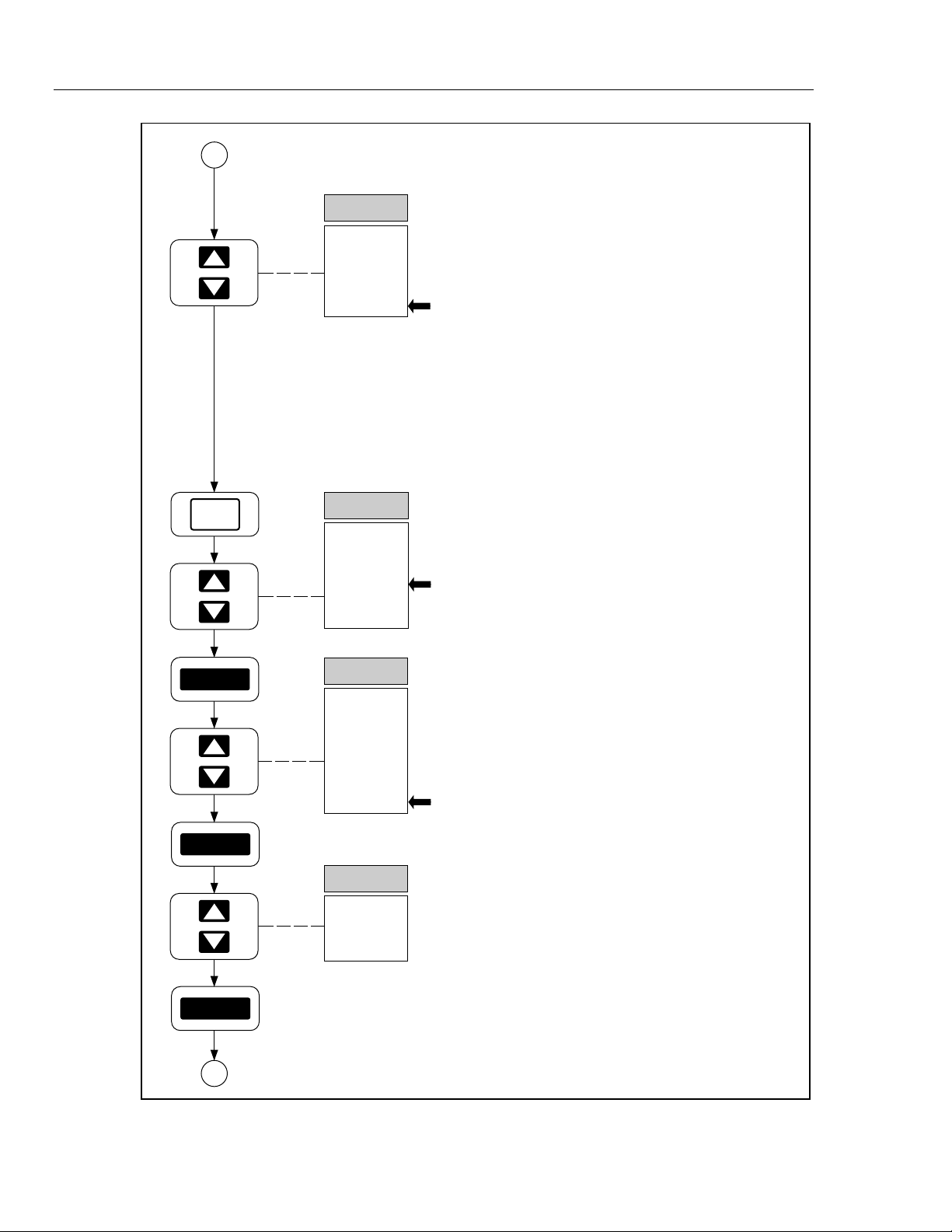
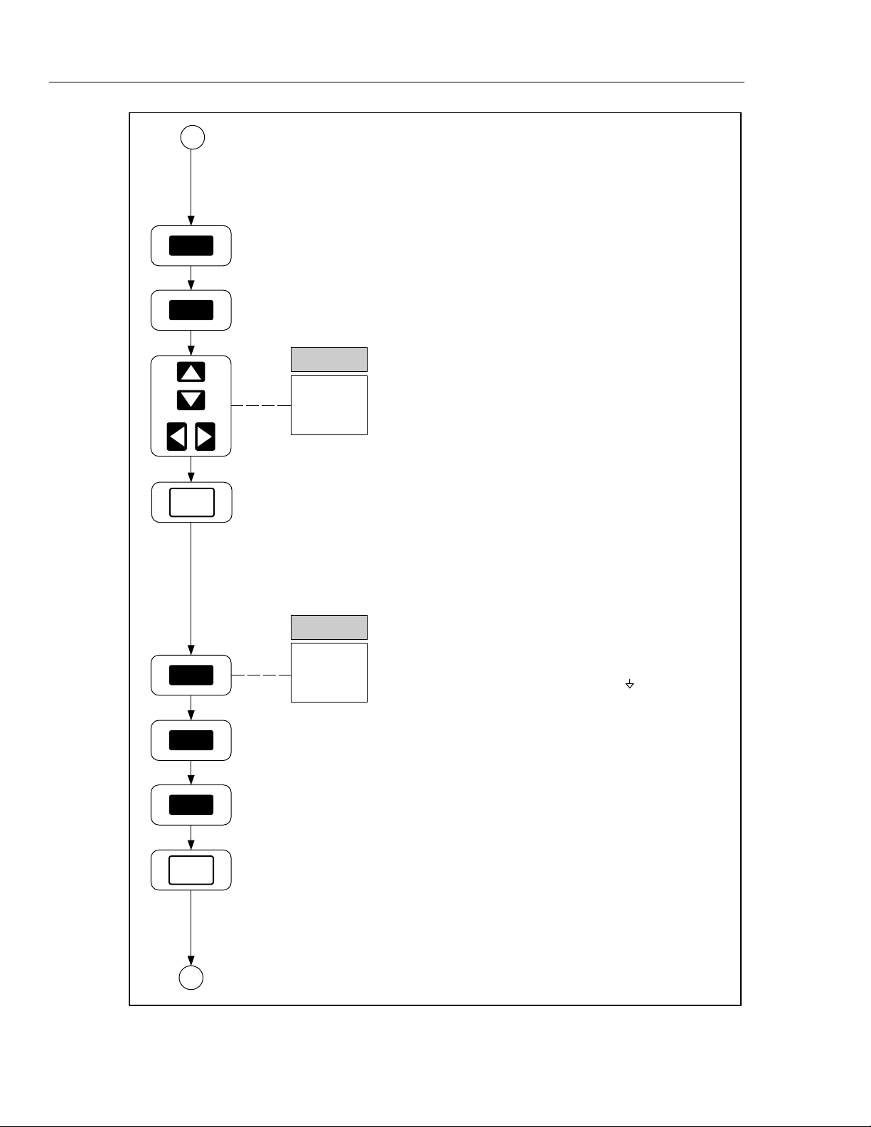
Applying power. Press the power switch to
apply power. Other power-on options include
Configuration-Reset, Display-Hold, and
Temperature-Toggle. [Figure 2-2]
Selecting a Channel. Up/down arrow keys
select a channel from 0 to 20. Channel 0
connections are on the front panel; Channels 1
through 20 connections are via the rear-panel
Universal Input Module. Select Channel 10.
[Figure 2-3]
Selecting a Function. Press the FUNC key to
open the function menu. Up/down arrow keys
select a function. Temperature unit °F/°C is set
with the Temperature-Toggle Power-On
procedure. Select VAC, then press ENTER.
[Figure 2-5]
ENTER
ENTER
A
SET FUNC
Auto
150.00 V
30.000 V
3.0000 V
300.00 mV
Selecting a Measurement Scale. Up/down
arrow keys select a measurement scale. AUTO
indicates autoranging, where the instrument
automatically selects the scale that provides the
best measurement resolution. Scale values are
maximum expected readings, e.g., the 30.000
VAC scale is for measurements of 30 VAC or
less. Select 150.00 V scale, then press ENTER.
Channel 10 is now configured. [Figure 2-5]
op79_1f.eps
Ten Minute Tour
xv
Page 18
2635A
Users Manual
A
FUNC
CH
20
...
10
...
0
SET FUNC
OFF
°F [°C]
Hz
Ω
VAC
V DC
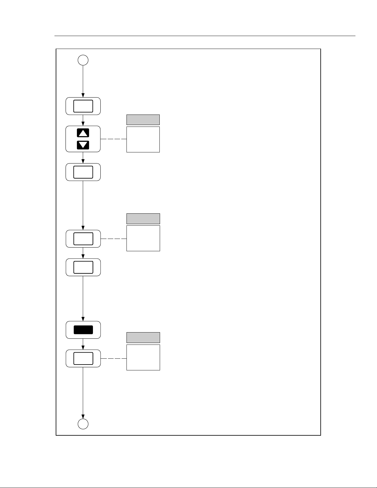
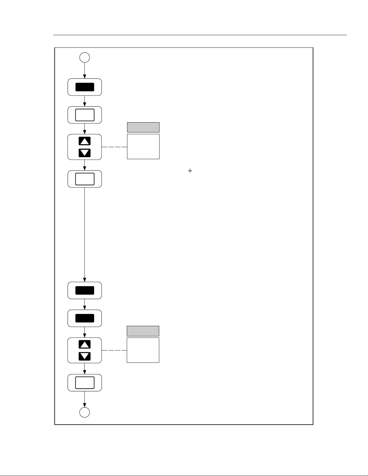
Selecting a Channel. Select Channel 0 with the
up/down arrow keys. Notice each key entry is
acknowledged with a short "beep." Try the
left/right arrow keys and notice a long beep.
Short beeps represent correct entries; long beeps
represent incorrect entries. [Figure 2-3]
Selecting a Function. Press FUNC to open the
function menu, use up/down arrow keys to select
Ω, then press ENTER. [Figure 2-6]
ENTER
ENTER
ENTER
B
SET FUNC
Auto
10.000 M
3.0000 M
300.00 k
30.000 k
3.0000 k
300.00
SET FUNC
2T
4T
Selecting a Measurement Scale. Select the
300.00 scale with up/down arrow keys, then
press ENTER. [Figure 2-6]
Selecting a Terminal Configuration.
Resistance measurements for channels 1
through 10 can use two channels (4 terminals) for
increased precision. For channels 0 and 11 to
20, only 2 terminal (2T) connections are allowed.
Press ENTER. [Figure 2-6]
Ten Minute Tour (cont)
xvi
op79_2f.eps
Page 19
B
MON
Ten Minute Tour
(continued)
MON
SCAN
SCAN
MON
0
10
SCAN
0
10
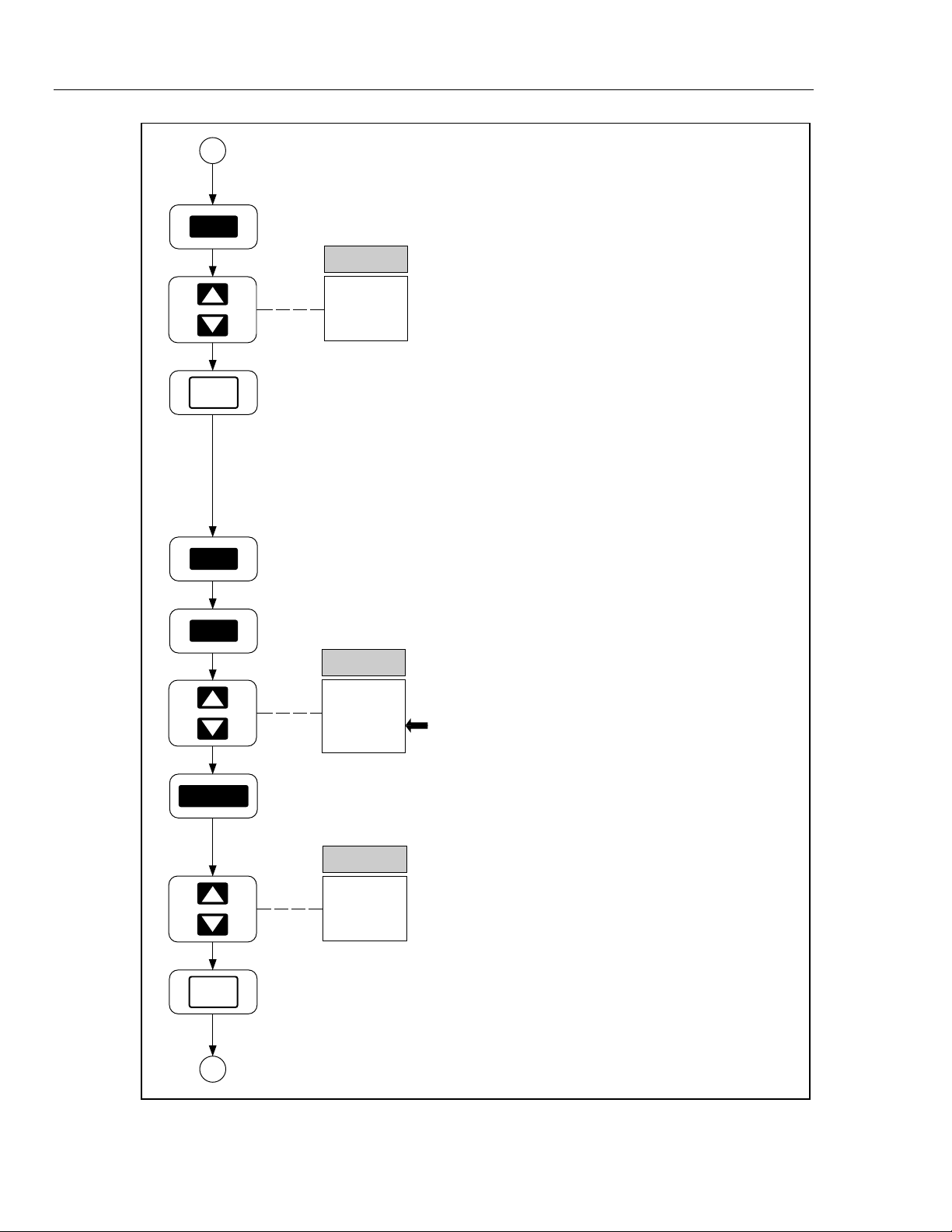
Selecting the Monitor Mode. Press the MON
key to enable monitoring. Up/down arrow keys
select any configured channel for monitoring.
When Channel 0 (Ω) is selected, touch the probe
tips together to measure test lead resistance.
Channel 10 (VAC) may have a small reading
because the input is unterminated. Press MON to
exit monitoring. [Figure 2-17]
Selecting the SCAN Mode. Press the SCAN
key to enable scanning. The display will indicate
which channel is being measured during the
scan. Monitor or Review can be enabled during
scanning. Measurement data can be routed to
the memory card, printer, or PC for display or
processing. Press SCAN to exit scanning.
[Figure 2-15]
SHIFT
SCAN
C
SCAN
0
10
Selecting the Single Scan Mode. Press the
SHIFT key, release, then press the SCAN key to
make a SINGLE measurement scan.
[Figure 2-15]
op79_3f.eps
Ten Minute Tour (cont)
xvii
Page 20
2635A
Users Manual
C
INTVL
CANCL
REVIEW
SHIFT
SET
0:00:00
REVIEW
LAST MIN MAX
0
10
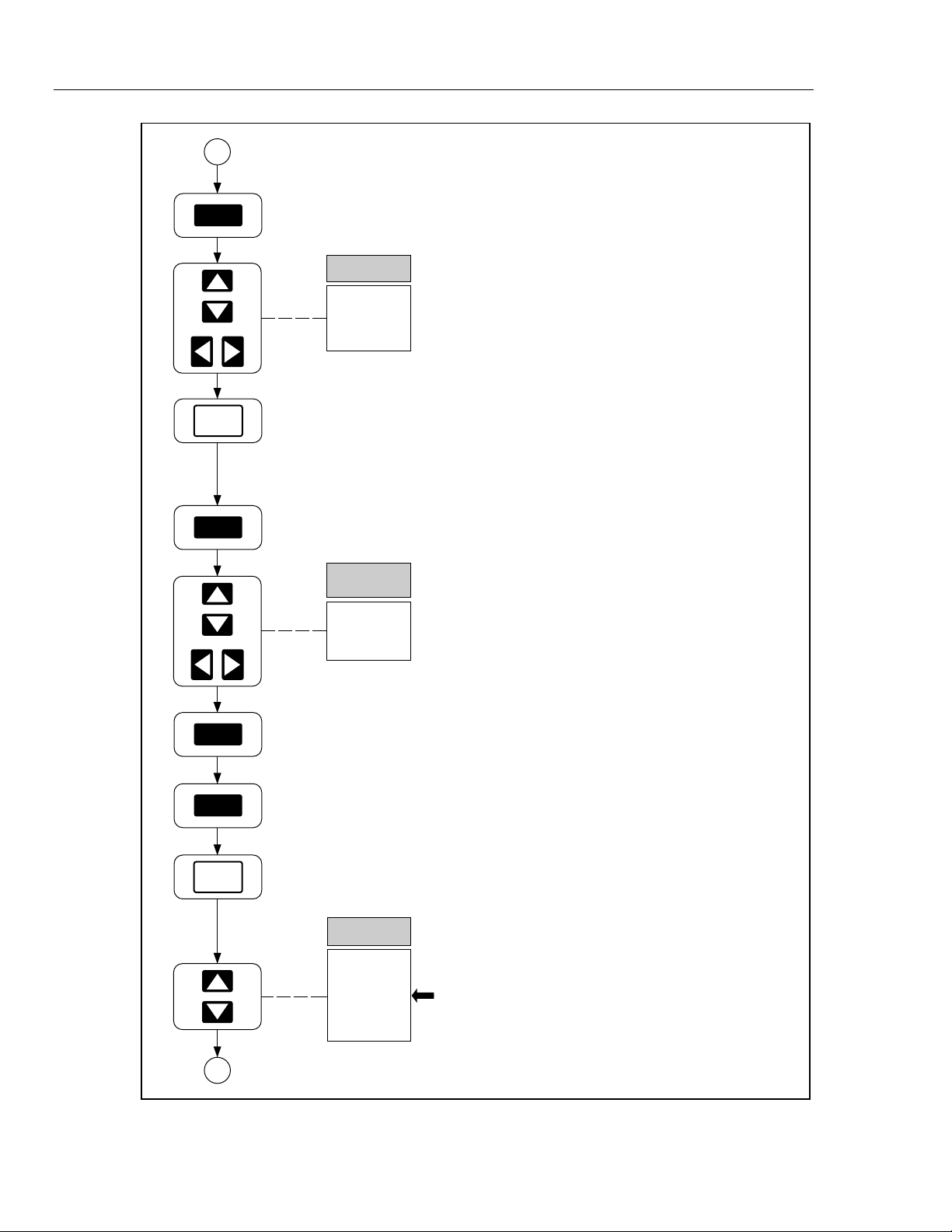
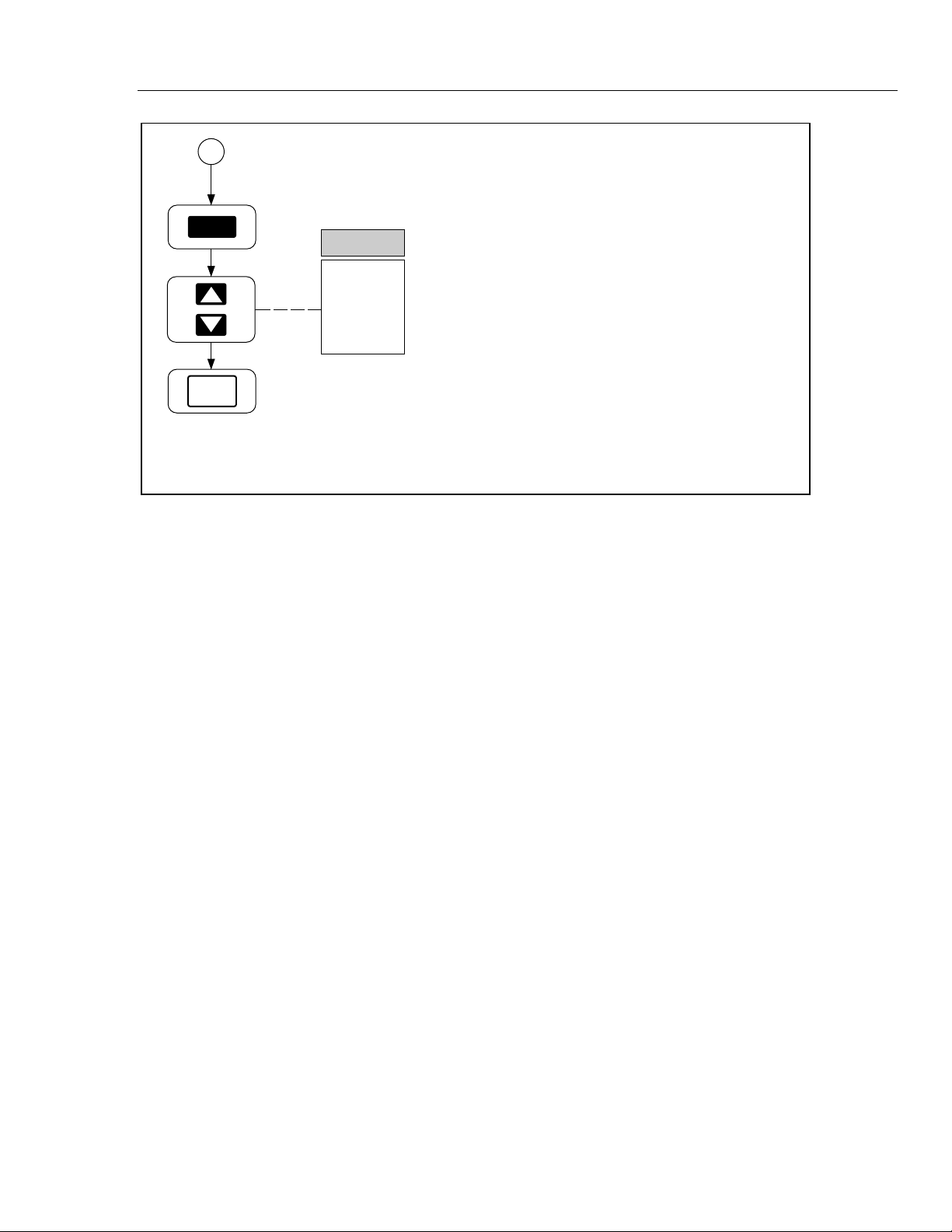
Setting the Scan Interval. Press the INTVL key
to open the interval menu. Up/down and left/right
arrow keys select 0:00:00 (default) to 9:99:99.
The format is HOURS:MINUTES:SECONDS.
The scan interval is the total time between the
start of each measurement cycle. 0:00:00
represents continuous scanning. Press CANCL
to exit. [Figure 2-11]
Selecting the Review Mode. Press the
REVIEW key to open the Review array. The
Review array holds the last, maximum, and
minimum readings during all previous scans for
all configured channels. Up/down arrow keys
select the channel, while left/right arrow keys
select LAST, MAX, and MIN. To CLEAR the
Review array, press the SHIFT key, release,
then press the REVIEW key. The Review array
is cleared automatically by changing any
parameter on any channel (including
Measurement Rate). Press CANCL to exit.
[Figure 2-18]
REVIEW
CANCL
D
20
...
10
...
0
CH
Ten Minute Tour (cont)
Select Channel 10. Select Channel 10 with the
up/down arrow keys. [Figure 2-3]
op79_4f.eps
xviii
Page 21
D
ALRM
Ten Minute Tour
(continued)
CANCL
Mx+B
CANCL
SET ALARM
1
2
SET Mx+B
M
+001.00
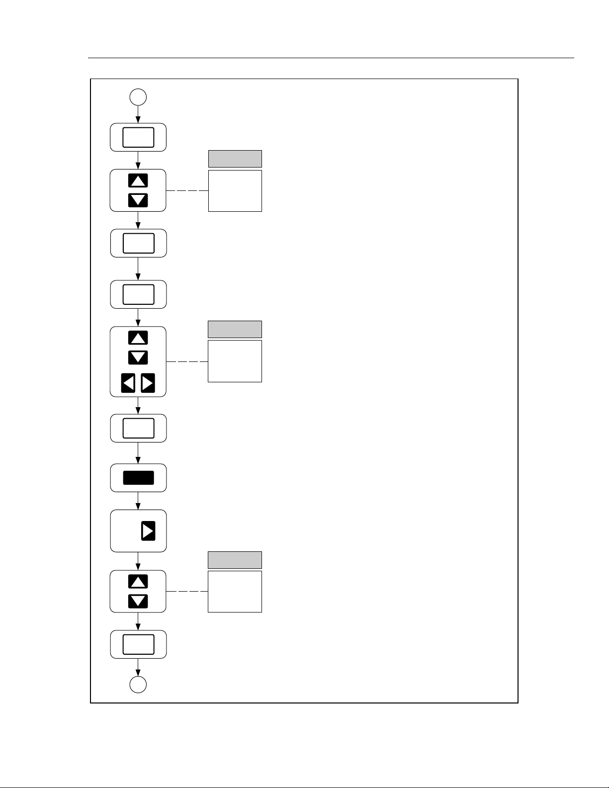
Selecting Alarms. Press the ALRM key to open
the alarm menu. Each configured channel can
have two alarm limits assigned. An alarm is set
when a reading is below or above an alarm limit.
Configuration starts with an alarm limit selection,
1 or 2. Press CANCL to exit. [Figure 2-13]
Setting Mx+B Scaling. Press the Mx+B key to
open the Mx+B menu. Up/down and left/right
arrow keys select the digits for the first parameter
(M) (default +001.00). The effect of Mx+B scaling
is to take a measurement (x) and modify it by
multiplying the measurement with M and then
adding an offset B (configured after M is set). For
example, Mx+B=+1.5x+25 applied to a
measurement of 20.000 would display
1.5(20.000) + 25 = 55.000. Press CANCL to exit.
[Figure 2-14]
SHIFT
CANCL
E
RAtE
FASt
SLO
Selecting the Measurement Rate. Press the
SHIFT key, release, then press the Right Arrow
key to open the RATE menu. During the
measurement portion of the scan interval, the
measurement rate can be FASt (Fast) or SLO
(Slow). The slow rate gives full 5-digit
measurement resolution, while the fast rate gives
only 4-digit resolution. The advantage of a fast
measurement rate is more readings during
continuous scanning or low scan intervals. Press
CANCL to exit. [Figure 2-12]
op79_5f.eps
Ten Minute Tour (cont)
xix
Page 22
2635A
Users Manual
E
SHIFT
INTVL
CANCL
TOTAL
SHIFT
yEAR
94
totAL
0
Setting Date and Time. Press the SHIFT key,
release, then press the INTVL key to open the
date and time (CLOCK) menu. Up/down and
left/right arrow keys select the YEAR 00 to 99.
For the complete procedure, this is followed by
MONTH:DAY and HOURS:MINUTES. Press
CANCL to exit. [Figure 2-21]
Selecting the Totalizer Feature. Press the
TOTAL key to open the totalizer display. The
totalizer operates independently as a separate
instrument function. Contact closures or voltage
transitions between pins Σ and on the rear
panel DIGITAL I/O connector are totaled and
displayed by pressing the TOTAL key. To ZERO
the total (already 0 in this example), press the
SHIFT key, release, then press the TOTAL key
again. Press CANCL to exit. [Figure 2-20]
TOTAL
CANCL
F
Ten Minute Tour (cont)
op79_6f.eps
xx
Page 23
F
SHIFT
MON
CANCL
tRIg
ALAr
On
OFF
Ten Minute Tour
Selecting Triggering Options. Press the SHIFT
key, release, then press the MON key to open
the TRIGS option menu. A trigger option can
trigger scanning, instead of using the SCAN key.
OFF indicates no triggering option; ON indicates
the external trigger option is active (a contact
closure or voltage transition between pins TR and
on the rear panel ALARM OUTPUTS connector);
ALAr (Alarm) indicates scan triggering when a
monitored channel goes into Alarm. Press
CANCL to exit. [Figure 2-19]
(continued)
SHIFT
LIST
CANCL
G
bAUd
38400
...
300
Setting the Communication Parameters.
Press the SHIFT key, release, then press the
LIST key to open the COMM menu. The
communication parameters configure the rearpanel RS-232 interface for printer and PC
operations. The first selection is bAUd (Baud)
with rates from 300 to 38400 baud. For the
complete procedure, this is followed by parity,
flow control and echo. Press CANCL to exit.
[Figure 5-2]
op79_7f.eps
Ten Minute Tour (cont)
xxi
Page 24
2635A
Users Manual
G
LIST
CANCL
SHIFT
FILES
ENTER
LISt
dir
LASt
dESt
both
Print
CArd
nonE
Setting the LIST Parameters. Press the LIST
key to open the LIST menu. LIST is used to print
out all the measurements from the Review Array,
or print out a directory of all the files on the
memory card by selecting dir (Directory). To use
LIST, a printer (or PC) must be connected to the
RS-232 port. Press CANCL to exit. [Figure 5-4]
Setting the DESTINATION Parameter. Press
the SHIFT key, release, then press the FILES
key to open the MODE menu. CArd (Card)
routes data to the memory card; Print (Print)
routes data to the RS-232 connector to a printer
(or PC); both (Both) routes data to both
destinations, and nonE (None) to neither
destination. Select CArd and press ENTER.
[Figure 5-3]
CANCL
H
MODE
trAnS
ALAr
ALL
Selecting the Destination Mode. ALL (All)
sends all measurement data to the destination
device (Memory Card in this example); ALAr
(Alarm) send all measurement data to the
destination device when any scanned channel is
in alarm; trAnS (Transition) sends all
measurement data to the destination device
when any scanned channel transitions into or out
of an alarm condition. Press CANCL to exit.
[Figure 5-3]
op79_8f.eps
Ten Minute Tour (cont)
xxii
Page 25
H
Ten Minute Tour
(continued)
FILES
CANCL
FILES
Init
StAt
dir
dAtA
SEtUP
Selecting the File Options. Press the FILES
key to open the Files menu. This menu selects
the memory card functions. SEtUP (Setup)
selects card functions for instrument
configuration files (SEtxx); dAtA (Data) selects
card functions for measurement data files
(dAtxx); dir (Directory) lists the number of
kilobytes free on the card and the name and size
of each SEtxx and dAtxx file; StAt (Status) lists
which SEtxx and dAtxx files are currently active
and percentage of the card that is used; Init
(Initialize) formats a blank card or erases and
formats a used card. Press CANCL to exit.
[Figure 3-3]
op79_9f.eps
Ten Minute Tour (cont)
xxiii
Page 26

2635A
Users Manual
xxiv
Page 27

Chapter 1
Preparation for Use
Title Page
Introduction....................................................................................................... 1-5
Operating Modes............................................................................................... 1-5
Front Panel Operation................................................................................... 1-7
Memory Card Operation............................................................................... 1-7
Computer Operation...................................................................................... 1-8
Printer Operation........................................................................................... 1-8
Modem Operation......................................................................................... 1-8
Measurement Capabilities................................................................................. 1-9
Mx+B Scaling............................................................................................... 1-9
Alarms........................................................................................................... 1-9
Totalizer Channel.......................................................................................... 1-9
Alarm Outputs and Digital I/O...................................................................... 1-9
Applications Software....................................................................................... 1-9
Hydra Starter Package................................................................................... 1-10
Hydra Logger................................................................................................ 1-10
Options and Accessories ................................................................................... 1-10
Memory Card Reader.................................................................................... 1-10
Connector Set, 2620A-100............................................................................ 1-10
Setting Up the Instrument.................................................................................. 1-11
Unpacking and Inspecting the Instrument..................................................... 1-11
Adjusting the Handle .................................................................................... 1-12
Connecting the Instrument to a Power Source.............................................. 1-12
AC Operation............................................................................................ 1-13
DC Operation............................................................................................ 1-13
Input Channels .............................................................................................. 1-13
Measurement Connections................................................................................ 1-14
Using Shielded Wiring.................................................................................. 1-14
Crosstalk........................................................................................................ 1-14
Universal Input Module Connections........................................................... 1-14
Alarm Outputs Connections.......................................................................... 1-17
DC Power.................................................................................................. 1-17
Alarm Outputs .......................................................................................... 1-17
External Trigger Input .............................................................................. 1-17
Digital I/O Connections................................................................................ 1-18
Digital I/O................................................................................................. 1-18
1-1
Page 28

2635A
Users Manual
Totalizer Input .......................................................................................... 1-18
Controls and Indicators ..................................................................................... 1-19
Front Panel Controls ..................................................................................... 1-19
Front Panel Indicators................................................................................... 1-19
1-2
Page 29

Preparation for Use
Introduction
1
1-3
Page 30
2635A
Users Manual
HYDRA
COM
SERIES II
300V
MAX
REVIEW
LAST
V
ALRM
FUNC
CANCEL
Mx+B
mVDCAC
M
ENTER
mA
Hz
k
INTVL
CLOCK
RATE
SHIFT
LOCAL
BUSY BATT
FILES
MODE
LIST
COMM
CH
REVIEW
SCAN
CLEAR
SINGLE
MON
TOTAL
TRIGS
ZERO
OP80F.EPS
1-4
Page 31

This manual contains information and warnings that must be followed to
ensure safe operation and keep the instrument in safe condition.
Introduction
The Fluke 2635A Hydra Series II Data Bucket is a 21-channel data logging instrument
that measures and records the following electrical and physical parameters: dc volts, ac
volts, resistance, frequency, and temperature. Temperature measurements are via
thermocouples or resistance-temperature detectors (RTDs). Other parameters can be
measured with an appropriate transducer, such as air pressure/vacuum (using a Fluke
PV350 transducer module) or DC current (using a Fluke 2600A-101 shunt resistor).
When the instrument scans channels configured for measurement, readings can be
displayed, printed out, and recorded. Virtually any analog input may be applied without
external signal conditioning. The inputs for channels 1 through 20 are via a Universal
Input Module, which plugs into the rear of the unit for a quick connect/disconnect
capability. Channel 0 measurements are via the front panel input jacks using test leads
(supplied). For a quick introduction to the operation of the instrument, complete the TenMinute Tour at the front of this manual. A summary of the Hydra Series II Data Bucket
features is provided in Table 1-1 and complete specifications in Appendix A. Figure 1-1
shows the instrument front and rear panels.
NOTE
Preparation for Use
Introduction
1
Operating Modes
The Data Bucket may be used in a wide variety of applications using one or more of five
operating modes:
• Front Panel Operation
• Memory Card Operation
• Computer Operation
• Printer Operation
• Modem Operation
1-5
Page 32

2635A
Users Manual
Table 1-1. Data Bucket Features
• Channel Scanning
Can be continuous scanning, scanning at an interval time, single scans, or triggered (internal or
external) scans. Channel Monitoring may be used while scanning.
• Channel Monitoring
Make measurements on a single channel and view these measurements on the display.
• Memory Card
Store measurement data and meter configuration setup data on a removable nonvolatile RAM
card.
• Multi-Function Display
Primary display shows measurement readings; also used when setting numeric parameters.
Secondary display used for numeric entries, channel number selection and display, status
information, and operator prompts.
Annunciator display used to show measurement units, alarms review parameters, remote status,
and configuration information.
• Front-Panel Operation
Almost all operations can be readily controlled with the front panel keys.
• Measurement Input Function and Range
Volts dc (VDC), volts ac (VAC), frequency (HZ), and resistance (e) inputs can be specified in a
fixed measurement range. Autoranging, which allows the instruments to use the measurement
range providing the optimum resolution, can also be selected.
• Temperature Measurement
Thermocouple types J, K, E, T, N, R, S and B, and Hoskins Engineering Co. type C are supported.
Also, DIN/IEC 751 Platinum RTDs are supported.
• Totalize Events on the Totalizing Input
• Alarm Limits and Digital Output Alarm Indication
• Four-Terminal Resistance Measurements (Channels 1 through 10 only)
• RS-232 Computer Interface Operation
• Measurement Rate Selection
• Nonvolatile Memory
Storage of minimum, maximum, and most recent measurements for all scanned channels.
Storage of Computer Interface setup, channel configurations, and calibration values.
Internal storage of measurement data: storage for 100 scans of up to 21 channels, accessible only
through the computer interface.
1-6
Page 33

Preparation for Use
Operating Modes
1
Ground Terminal.
Connects mainframe
to ground.
90-264V
50/60 Hz
15VA
!
ALARM OUTPUTS DIGITAL I/O
+–0123TR
+–0123TR 01234567Σ
9-16 V
DC PWR
CAUTION
+30V
AC Power Connector.
Connect to any line source
of 90 to 264 VAC (50/60 Hz).
01234567Σ
!
MEETS Vfg. 243/1991
COMPLIES WITHFCC-15B
FOR FIRE PROTECTION
REPLACE WITH T 1/8A 250V (SLOW) FUSE
RS-232C
54321
GND
[CTS]
[2635A ONLY]
DTR
Universal Input Module.
Directly wires 20 analog inputs
(Channels 1 to 20) without
external signal conditioning.
2620A 2625A 2635AMODEL:
IEC 664 INSTALLATIONCATEGORY II
IEEE STD-488 PORT
6789
[DSR]
TX
RX
[RTS]
SH1, AH1, T5, L4, SR1, RL1, DC1, DT1, PP0, C0, E1
Alarm Outputs Connector.
Outputs alarms for channels 0 to 3,
DC power inputs for DC operation
(9 to 16V dc), inputs external scan
trigger (TR and ).
Figure 1-1. Data Bucket Front and Rear Panels
Front Panel Operation
Front panel operations include configuration of channels in preparation for scanning
operations and simple multimeter operation by placing the instrument in the Monitor
mode then using the front panel jacks and test leads (channel 0) for measurements. Front
panel operations are discussed in Chapter 2.
Memory Card Operation
An adjunct to stand-alone front panel use are operations that use the memory card
feature. The memory card is a Static Random Access Memory (SRAM) device that plugs
into a slot on the Data Bucket front panel. An internal battery maintains the integrity of
the stored data. An empty 256K-byte card stores 8500 scans of 4 channels, 4500 scans of
10 channels, or 2500 scans of 20 channels. A typical display while scanning using the
memory card is shown in Figure 1-2. The PC-compatible memory card can be used to
store measurement files and configuration files. Data extraction from the card requires a
Digital I/O Connector.
Outputs alarms for
channels 4 to 20 (default),
inputs totalizer (
Σ and ).
RS-232C.
Interfaces instrument with
a printer, PC or modem.
op01f.eps
1-7
Page 34

2635A
Users Manual
personal computer (PC), where data can be sent from the Data Bucket to the PC over an
RS-232 link (up to a 38,400 baud rate), or the card can be removed and taken to a PC
equipped with a memory card reader (see Options and Accessories). Memory card
operations are discussed in Chapter 3.
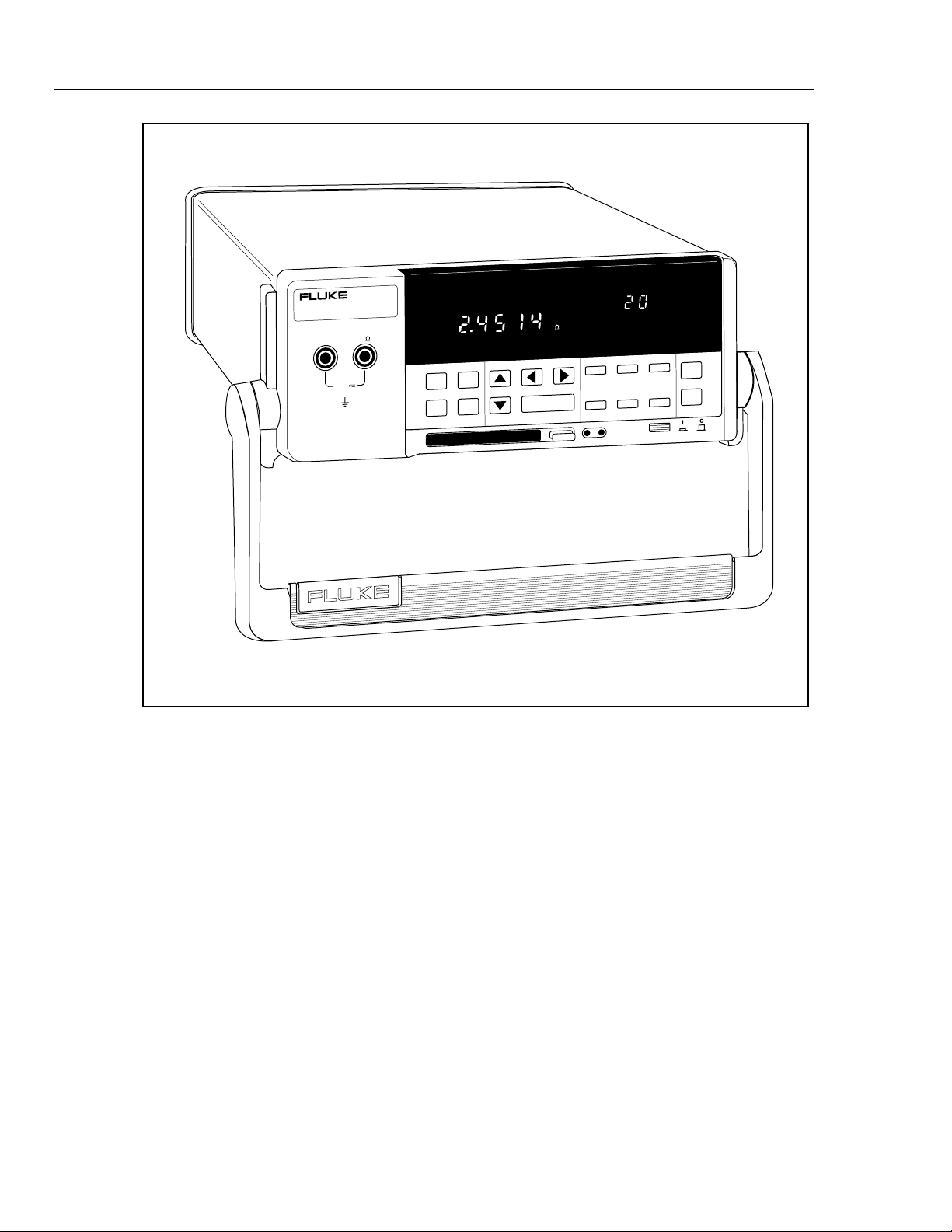
SCAN Annunciator.
Indicates the instrument is
in the Scan mode (vs
Monitor or Review mode).
Memory Card Status.
Card has used 42% of its
capacity. After 99%, FULL
is displayed.
Figure 1-2. Typical Front Panel Display While Scanning
Computer Operation
The Data Bucket can serve as a front-end data acquisition unit for PC-based operations,
operating over an RS-232 link. The applications software for operating the RS-232 link
includes the supplied Hydra Starter Package (Starter) and optional Hydra Logger
(Logger) (see "Applications Software" below). Computer operations are discussed in
Chapter 4.
ALARM Annunciator.
Indicates that one (or
more) of the scanned
channels is in alarm.
SCAN
ALARM
PRN (Print) Annunciator.
Indicates the destination
for the data is the memory
card or printer.
18 (Channel) Scanned.
Indicates the channel
being measured during
channel scanning.
PRN CH
CH (Channel) Annunciator.
Indicates the number in the
secondary display is a
channel.
op02f.eps
1-8
Printer Operation
Measurement data from the Data Bucket can be routed to a printer via an RS-232 link.
At the completion of each scan cycle, measurement data is printed, providing hardcopy
output. Any compatible printer with a serial input may be used. Printers with a parallel
input may be used if they are equipped with a serial-to-parallel adapter. Printer
operations are discussed in Chapter 5.
Modem Operation
An RS-232 link between the Data Bucket and a modem allows data transfers over
telephone lines. Operation is similar to computer operations, except there is a modem
link instead of a direct RS-232 connection. The modem may be electronic or
programmable/electronic (Hayes-compatible). Modem operations are discussed in
Chapter 6.
Page 35

Measurement Capabilities
Before scanning is enabled, the Data Bucket channels are configured for measuring the
selected electrical or physical parameter (volts dc, volts ac, temperature, etc.). Readings
have five digits of resolution, for example, 15.388 VAC. Scanning collects measurement
data, while the monitor mode can monitor a channel with or without scanning. The
review mode stores the maximum, minimum and last readings. Mx+B scaling and alarm
attributes can be applied to each configured channel. A totalizer channel is supplied as a
separate feature, and digital I/O functions are provided by the rear panel connectors,
ALARM OUTPUTS, and DIGITAL I/O.
Mx+B Scaling
The Mx+B scaling attribute allows readings to be modified to better represent what is
being measured. The M represents a multiplier and B represents an offset. For example,
a normal reading of 3 volts can be multiplied by M=+100 and offset by B=-25, to display
275 (3x100 - 25= 275). Mx+B scaling can be applied to any configured channel. This
feature is especially useful to scale transducer outputs for exact measurement displays.
Alarms
The alarms attribute allows readings that rise or fall below preset levels to alert the
operator and trigger an action. For example, if you are monitoring temperature and want
to have 100ºC cause an alarm condition, this can be programmed as part of the channel
configuration. Alarm conditions are reported as part of the measurement scan data and
can be used to trigger scanning and assert a logic low on a rear panel ALARM
OUTPUTS or DIGITAL I/O connector terminal for interface with external equipment.
Two alarms can be assigned to any configured channel. If Mx+B scaling is applied, the
alarms are based on the scaled values.
Preparation for Use
Measurement Capabilities
1
Totalizer Channel
The totalizer channel counts contact closures or voltage transitions. The maximum count
is 65,535. The connection is at the rear panel ALARMS OUTPUTS connector, terminals
SUM and GROUND. The Data Bucket continuously samples the totalizer input on the
rear panel, independently from Hydra's scanning and other activities.
Alarm Outputs and Digital I / O
Alarm outputs are available on the rear panel ALARM OUTPUTS and DIGITAL I/O
connectors. The four ALARM OUTPUT lines are permanently assigned to signal alarms
for channels 0, 1, 2, and 3. The eight DIGITAL I/O lines can be used to signal alarm
conditions for channels 4 to 20. All input/output lines are transistor-transistor-logic
(TTL) compatible. For operations that do not use a computer interface, these are the only
functions of the ALARM OUTPUTS and DIGITAL I/O connections. When a computer
interface is used, the DIGITAL I/O lines can be assigned in the applications software for
a variety of inputs or outputs. The ALARM OUTPUTS can also be assigned for I/O
operations if the dedicated alarm function is not used (which has priority).
Applications Software
PC applications software Hydra Starter (supplied) and Hydra Logger Package (Logger)
(optional) operate the instrument via the RS-232 computer interface. The software
packages are described in separate technical manuals; however, each is summarized
below.
1-9
Page 36

2635A
Users Manual
An extensive command set allows the user to develop custom software in GWBASIC,
QBASIC, and QuickC. The command set is discussed in Chapter 4.
Hydra Starter Package
Starter is a DOS based, menu-driven software package used to transfer configuration
data from and to the instrument, log measurement data collected by the instrument,
extract data from the memory card, and manage the acquired data. During operation,
Starter displays readings of all channels in real time and can automatically log the data to
a Lotus 1-2-3 compatible file.
Hydra Logger
Hydra Logger (model 2635A-901) is an optional Windows-based package that allows
complete setup, data collection and data conversion from up to two Hydra units. Logger
communicates over the RS-232 port on a personal computer and may be used with
telephone models. Hydra Logger with Trending (model 2635A-902) includes a
comprehensive trending package that simulates a chart recorder. A brochure with
complete details is available.
Options and Accessories
Options and accessories include measurement transducers, cables, applications software,
carrying case and other items, all of which are summarized in Table 1-2.
Memory Card Reader
Data Bucket measurement data and configuration setups may be stored on a memory
card that is inserted into the slot on the instrument front panel (see Figure 1-1). To
review and analyze the recorded data, the memory card data can be routed to a PC via
the RS-232 interface, or the memory card can be removed and taken to a PC equipped
with a memory card reader. The memory card reader (optional) is external to the PC and
connects to a PC parallel port (LPT1, LPT2, etc.). The memory card reader is configured
as another PC drive, e.g., the D: drive. Memory card files include data files
(dAtxx.HYD) and configuration setups (SEtxx.HYD). The PC manipulates these files
using applications software Starter (supplied) and Logger (optional). The selected
memory card reader must read SRAM cards and meet Personal Computer Memory Card
International Association (PCMCIA)/Japan Electronics Industrial Development
Association (JEIDA) standards. This memory card application meets PCMCIA standards
release 2.0.
Connector Set, 2620A-100
The 2620A-100 is a complete set of input connectors: one Universal Input Module, one
ALARM OUTPUTS connector, and one DIGITAL I/O connector. The use of additional
connector sets allows quick equipment interface to several wiring setups.
1-10
Page 37

Preparation for Use
Setting Up the Instrument
Table 1-2. Options and Accessories
MODEL DESCRIPTION
2635A-901 Hydra Logger Software (Windows)
2635A-902 Hydra Logger Software with Trending (includes 2640A-904)
2640A-904 Trend Link for Fluke Software
2620A-100 I/O Connector Set; includes Universal Input Module, Digital I/O Connector and
Alarm Output Connector
2620A-101 10 Ohm Shunt Set (set of 12 shunts)
263XA-803 Memory Card Reader. Connects to PC parallel printer port
263XA-804 256Kb SRAM Memory Card (one included with instrument)
263XA-805 1Mb SRAM Memory Card
263XA-806 2Mb SRAM Memory Card
263XA-807 4Mb SRAM Memory Card
1
RS40 RS-232 Cable. DB9 to DB25
RS41 RS-232 Modem Cable. DB9 to DB25
RS42 RS-232 Printer Cable. DB9 to DB25
RS43 RS-232 Cable. DB9 to DB9
C40 Soft Carrying Case
C44 Transit Case
M00-200-634 Rackmount Kit
26XXA-600 Portable Battery Pack
688868 Hydra Series II Service Manual
Setting Up the Instrument
Setting up the instrument includes all preparatory information, from unpacking the
instrument to application of power.
Unpacking and Inspecting the Instrument
The following items are included in the shipping container:
• Model 2635A Data Bucket instrument
• This manual
• Starter Applications software (floppy disks and manual)
• Universal Input Module
• ALARM OUTPUTS and DIGITAL I/O connectors
• Channel 0 (front panel)TL70A test leads
1-11
Page 38

2635A
Users Manual
• Line power cord
• Type "T" Thermocouple
• 256K-byte Memory Card
Carefully remove the instrument from its shipping container and inspect the instrument
for possible damage or missing items. If the instrument is damaged or anything is
missing, contact the place of purchase immediately. Save the container and packing
material in case you have to return the instrument.
Rotate the rear feet of the instrument 180 degrees so that their support pads extend
slightly below the bottom of the case.
Adjusting the Handle
The handle can be positioned to four angles: one for carrying, two for viewing, and one
for handle removal. To change the angle, simultaneously pull both handle ends outward
to hard stops (about 1/4-inch on each side) and then rotate the handle to one of the four
stop positions shown in Figure 1-3. With the handle in the straight-up removal position,
you can disengage and free one handle side at a time.
1. Viewing Position
2. Alternative Viewing Position
4. Removal Position
3. Carrying Position
(to Remove, Pull Ends Out)
Figure 1-3. Adjusting the Handle
Connecting the Instrument to a Power Source
The instrument can be connected to an ac or dc source. Connections are shown in Figure
1-4 and described below.
Pull One End Out and Towards You.
Then Pull the Other End Out.
V
COM
Ω
300V
MAX
op03f.eps
1-12
Page 39

LINE CORD (AC OPERATION)
FOR FIRE PROTECTION
90-264V
50/60 Hz
15VA
!
ALARM OUTPUTS DIGITAL I/O
+–
0123TR
+–0123TR 01234567
9-16 V
DC PWR
CAUTION
01234567
+30V
!
REPLACE WITH T 1/8A 250V (SLOW) FUSE
MEETS Vfg. 243/1991
COMPLIES WITHFCC-15B
EXTERNAL BATTERY (DC OPERATION)
Σ
Σ
[2635A ONLY]
GND
[CTS]
RS-232C
54321
TX
RX
DTR
Preparation for Use
Setting Up the Instrument
2620A 2625A 2635AMODEL:
IEC 664 INSTALLATIONCATEGORY II
IEEE STD-488 PORT
6789
[DSR]
SH1, AH1, T5, L4, SR1, RL1, DC1, DT1, PP0, C0, E1
[RTS]
1
WARNING: If voltages greater than 30V are to be measured, a safety ground must be attached
to the rear panel ground connector when the instrument is operated from battery power.
Figure 1-4. Connecting the Instrument to a Power Source
Warning
To avoid shock hazard, connect the instrument power cord to a
power receptacle with earth ground.
AC Operation
Plug the line cord into the connector on the rear of the instrument. The instrument
operates on any line voltage between 90 and 264V ac without adjustment, and at any
frequency between 45 and 440 Hz. However, the instrument is warranted to meet
published specifications only at 50 or 60 Hz.
DC Operation
The instrument may be operated from a DC voltage between 9 and 16 volts, consuming a
nominal 4 watts. Connection is made at the rear panel ALARM OUTPUTS connector,
pins (+) and (-). If both ac and dc sources are connected simultaneously, ac is used if it
exceeds approximately 8.3 times dc. Automatic switchover occurs between ac and dc
without interruption.
Warning
If voltages greater than 30V are to be measured, a safet y
ground must be attached to the rear panel ground connector
when the instrument is operated from battery power.
op04f.eps
Input Channels
The instrument provides one input (channel 0) on the front panel and 20 inputs (channels
1 through 20) through a connector on the rear panel. Channels 0, 1, and 11 can measure a
maximum of 300V dc or ac rms; all other channels can measure a maximum of 150V dc
or ac rms.
1-13
Page 40

2635A
Users Manual
Caution
Do not exceed the specified input voltage l evels or equipment
damage could result.
Measurement Connections
W Warning
To avoid electric shock:
• When the input module is installed, consider all channels
with connections as accessible terminals that may be
hazardous live.
• Disconnect the input module before touching or changing
external wiring.
Input connections include the front panel terminals (channel 0), rear panel connections
using the Universal Input Module (channels 1 through 20), and I/O functions using the
ALARM OUTPUTS and DIGITAL I/O connectors. The instrument is protected from
channel configuration errors. For example, accidentally applying 300V ac to a channel
configured for resistance measurements will not damage the instrument.
Using Shielded Wiring
Shielded wires and sensors (such as thermocouples) should be used in environments
where "noisy" voltage sources are present. When shielded wiring is used, the shield is
normally connected to the L (low) input terminals for each channel. Alternate
configurations should be examined for each equipment application.
Crosstalk
The instrument allows the mixing of various types of measurement. A phenomenon
known as crosstalk can cause one signal to interfere with another and thereby introduce
measurement errors. To reduce the effects of crosstalk in making measurement
connections, do the following:
• Keep any input wiring carrying ac volts signals physically separate from the input
wiring of other sensitive channels.
• Avoid connecting inputs with ac volts signals adjacent to sensitive channel inputs.
Leave unconnected channels between the inputs, if possible.
• Avoid connecting inputs with ac volts signals to any channel 10 numbers away from
a sensitive channel (i.e., 4-terminal input channels).
• Avoid tying L (low) or (especially) H (high) inputs of a sensitive channel to earth
(chassis) ground. This is very important in resistance measurements.
• Avoid high-source impedances on sensitive channels, or minimize the capacitance of
the sensitive channel to earth (chassis) ground for high impedance inputs.
1-14
• Whenever high ohms measurements (>10 kΩ) must be made accurately, avoid
connecting any inputs carrying ac volts signals.
Measurement errors introduced by crosstalk are discussed in Appendix B.
Universal Input Module Connections
For channels 1 through 20, use the H (high) and L (low) inputs on the rear panel
Universal Input Module, as shown in Figure 1-5. Perform the following procedure to
make connections to the Universal Input Module:
Page 41

Preparation for Use
Measurement Connections
H
L
H
H
L
L
H
L
H
L
HL
H
L
H
L
H
L
H
H
L
H
L
H
L
L
H
L
H
L
H
H
L
L
H
HL
L
HL
STRAIN RELIEF
HL HLHLHLHLHLHLHLHLHL
20
1
HL HLHLHLHLHL HLHLHL
11121231341451561671781891910
LH
op05f.eps
Figure 1-5. Universal Input Module Connections
Warning
Inputs may be connected to live voltages. To avoid electric
shock, remove inputs from live voltages bef ore openi ng this
module.
1. Remove the module from the rear panel by pressing the release tab on the bottom of
the module and then pulling the module out of its connector.
2. Loosen the two large screws on top and open the module
3. Connect the wires to H (high) and L (low) for each channel.
4. Thread these wires through the strain-relief pins and out the back of the module.
5. Close the module cover, secure the screws, and insert the module in the connector at
the rear of the instrument until it latches in place.
Note
Channel 0 on the front panel does not support thermocouple
measurements.
Resistance and RTD measurements can be made with two terminals (one channel) or
four terminals (two channels). The four-terminal connection provides increased accuracy
(nominal 1%) over the two-terminal connection. Refer to Figure 1-6.
1-15
Page 42

2635A
Users Manual
SOURCE
(4-WIRE)
2-WIRE (2T) CONNECTION
1211 13 14 15 16 17 18 19 20
H L H LH LH LH LH LH LH LH LH L
SENSE
(4-WIRE)
H L H LH LH LH LH LH LH LH LH L
21 345678910
USE H AND L TERMINALS FOR ANY CHANNEL.
• CHANNEL 0 ON FRONT PANEL
• CHANNELS 1 THROUGH 20 ON REAR
PANEL INPUT MODULE (CHANNEL 8 SHOWN HERE).
4-WIRE (4T) CONNECTION
1211 13 14 15 16 17 18 19 20
SOURCE
(4-WIRE)
H L H LH LH LH LH LH LH LH LH L
RESISTANCE
OR
RTD SOURCE
1-16
SENSE
(4-WIRE)
H L H LH LH LH LH LH LH LH LH L
21 345678910
RESISTANCE
OR
RTD SOURCE
USE H AND L TERMINALS FOR TWO CHANNELS ON REAR PANEL INPUT MODULE.
CONNECTIONS FOR CHANNEL 8 ARE SHOWN HERE WITH CHANNEL 18 PROVIDING
THE ADDITIONAL TWO CONNECTIONS.
FOR EACH 4-WIRE CONNECTION, ONE SENSE CHANNEL (1 THROUGH 10) AND
ONE SOURCE CHANNEL (SENSE CHANNEL NUMBER +10 = 11 THROUGH 20) ARE USED.
Figure 1-6. Two-Terminal and Four-Terminal Connections
op06f.eps
Page 43

Alarm Outputs Connections
The eight-terminal rear panel ALARM OUTPUTS connector (Figure 1-7) serves three
functions: DC power, alarm outputs, and external trigger input. Each is described below.
Preparation for Use
Measurement Connections
1
Terminal
+
–
0
1
2
3
TR
DC Power
The instrument may be powered by a dc input between 9 volts and 16 volts allowing
remote operation from various battery sources or dc power supplies. Connect the
positive lead of the power supply to the + terminal and the negative lead to the terminal. If the instrument is going to measure voltages greater than 50 volts dc or ac
rms, also connect a ground wire between the rear panel ground lug and a suitable earth
(safety) ground point (see Figure 1-4).
Alarm Outputs
Terminals 0, 1, 2, and 3 are used to signal alarm conditions for channels 0, 1, 2, and 3
respectively using transistor-transistor-logic (TTL) voltage levels, referenced to the
GROUND terminal. Logic high is >+2.0 to <+5.5V dc; a logic low is 0.0 to +0.8V dc. If
a channel is not in alarm, the voltage output at a connector terminal is a logical high
(nominal +5V dc); if a channel is in alarm, the output is a logical low (nominal +0.7V
dc). Alarm outputs are set at the end of a scan interval. See Setting the Alarms in
Chapter 2 for more information. If the instrument is operated over the RS-232 computer
interface, the ALARM OUTPUTS can be assigned to I/O functions (assuming channels
0, 1, 2, and 3 are not configured for alarms). See the ALARM_DO_LEVEL command,
described in Chapter 4.
Function
Positive Input for DC Operation
Negative Input for DC Operation
Channel 0 Alarm Output
Channel 1 Alarm Output
Channel 2 Alarm Output
Channel 3 Alarm Output
External Trigger Input
Ground Terminal
Figure 1-7. ALARM OUTPUTS connector
+–
9-16 V
DC PWR
ALARM OUTPUTS
0123TR
op07f.eps
External Trigger Input
An external trigger input can serve the same function as the front panel SCAN key. A
contact closure between TR and GROUND or a TTL logical low applied to TR
(referenced to GROUND), will cause the instrument to scan. When the trigger input is
removed, scanning will stop. Scanning is initiated on the falling edge of the trigger
signal, which must be held logic low for at least 5 us and have been preceded by at least
100 ms of logic high. Logic high is +2.0 to +7.0V dc; a logic low is -0.6 to +0.8V dc.
See "Scan Triggering Options" in Chapter 2 for more information.
Perform the following procedure to make connections to the ALARM OUTPUTS
connector:
1. Remove the connector from the rear panel.
1-17
Page 44

2635A
Users Manual
2. Loosen the wire clamp screw for the associated terminal.
3. Feed the wire into the gap between the connector body and the wire clamp.
4. Tighten the wire clamp screw.
5. Insert the connector in the rear panel.
Digital I/O Connections
The ten-terminal rear panel DIGITAL I/O connector (Figure 1-8) serves two functions:
Digital I/O and Totalizer input. Each is described below.
Terminal
0
1
2
3
4
5
6
7
Σ
Digital I/O
Terminals 4 through 7 are used to signal alarm conditions for channels 4 through 20
(default setting) using TTL voltage levels, referenced to the GROUND terminal. Logic
high is >+2.0 to <+5.5V dc; a logic low is 0.0 to +0.8V dc. If a channel is not in alarm,
the voltage output at a connector terminal is a logical high (nominal +5V dc); if a
channel is in alarm, the output is a logical low (nominal +0.7V dc). Alarm outputs are
changed at the end of each scan. See "Setting the Alarms" in Chapter 2 for more
information. All alarm associations can be removed using computer commands, allowing
the I/O terminals to be assigned to other functions as determined by computer
commands. See the ALARM_ASSOC_CLR and related commands, described in Chapter
4.
Function
Input/Output Line 0
Input/Output Line 1
Input/Output Line 2
Input/Output Line 3
Input/Output Line 4
Input/Output Line 5
Input/Output Line 6
Input/Output Line 7
Totalizer Input
Ground Terminal
Figure 1-8. DIGITAL I/O Connector
DIGITAL I/O
234567
10
Σ
op08f.eps
1-18
Totalizer Input
The totalizer is an internal counter that sums contact closures or voltage transitions.
Connection is to the SUM terminal, referenced to GROUND. A contact closure and
opening, or a voltage transition rising edge will cause the totalizer to advance by one
count. The maximum count allowed is 65535 and the maximum count rate is 5 kHz.
Voltages trigger on a low-to-high transition at a nominal threshold of +1.4 volts. A
contact debounce feature is available when the instrument is operated through the RS232 computer interface using the TOTAL_DBNC command, described in Chapter 4.
Perform the following procedure to make connections to the DIGITAL I/O connector:
1. Remove the connector from the rear panel.
2. Loosen the wire clamp screw for the associated terminal.
3. Feed the wire into the gap between the connector body and the wire clamp.
Page 45

4. Tighten the wire clamp screw.
5. Insert the connector in the rear panel.
Controls and Indicators
The front panel (Figure 1-1) provides a multipurpose display and a set of control keys.
Each is described in the following paragraphs.
Front Panel Controls
The front panel keys (Figure 1-9) control all instrument operation: channel
configuration, instrument configuration, measurement functions, and
print/communications selections. Table 1-3 provides a summary of front panel key
functions.
Front Panel Indicators
The front panel indicators are divided into three portions: Primary Display (Figure 1-10),
Secondary Display (Figure 1-11), and Display Annunciators (Figure 1-12). Table 1-4
describes each annunciator function.
Preparation for Use
Controls and Indicators
1
FUNC ALRM
+
CANCL
REVIEW
LAST
MAX
MIN
REM
AUTO
INTVL FILES REVI EW
RATE
ENTER
Figure 1-9. Front Panel Keys
SCAN
MON
SET
Mx+B
CLOCK CLEAR
SHIFT LIST TOTAL
LOCAL COMM ZERO
BUSY BATT
FUNC
ALARM
°C °F RO
mV AC DC
Ω
Hz
x1Mk
Figure 1-10. Primary Display
MODE
F
LIMIT
12
HI
LO
OFF
CAL
SCAN
SINGLE
MONMx B
TRIGS
PRN
EXT
op09f.eps
CH
TR
op10f.eps
1-19
Page 46

2635A
Users Manual
REVIEW
LAST
REVIEW
LAST
MAX
MIN
MAX
MIN
FUNC
REM
AUTO
SCAN
MON
SET
Mx+B
ALARM
°C °F RO
mV AC DC
x1Mk
Figure 1-11. Secondary Display
FUNC
REM
AUTO
SCAN
MON
SET
Mx+B
ALARM
°C °F RO
mV AC DC
x1Mk
Figure 1-12. Annunciator Display
Ω
Ω
Hz
Hz
F
LIMIT
12
F
LIMIT
12
HI
LO
HI
LO
OFF
CAL
OFF
CAL
PRN
EXTCHTR
op11f.eps
PRN
EXTCHTR
op12f.eps
1-20
Page 47

Preparation for Use
Controls and Indicators
Table 1-3. Front Panel Keys Description
Key Description
F Calls up the menu to set the function for the channel
A Calls up the menu to set alarm limits S and T for the channel.
B Calls up the menu to set scaling on the channel.
C Used to exit any setup menu and return to Inactive Mode, without saving
settings you’ve selected thus far. Exceptions exist under the following two
conditions
1
If you cancel out of the alarm menu part way through defining alarm limit
just-made entries for alarm limit
If you cancel out of the Mx+B menu part way through defining the B value, any
just-made entries for the M value will still take effect.
This key also provides a handy way to remove the Totalizer value or Review
data from the display.
S will still take effect.
T, any
G D Used to change the channel number and to step through choices in any of the
setup menus. These arrow keys have an automatic repeat action when held
down for more than 1 second.
J H Used to step through choices in several of the setup menus. These arrow keys
have an automatic repeat action when held down for more than 1 second.
E Used to accept a selection just made in any setup menu.
I Allows you to change the scan interval. Scanning becomes continuous when
the interval is set to 0:00:00.
P Accesses menus related to memory card operation, including status, directory,
and manipulation of all SEtxx and dAtxx files.
N Calls up the Review array of MIN, MAX and LAST values to the display.
K Accesses secondary functions under various keys, as described below. When
this key is pressed, "SHIFt" appears on the right display, but automatically
disappears if you have not made a selection within 5 seconds or press
C.
L Prints out the Last values of the Review array or contents of the memory card
directory via the RS-232 computer interface.
O Calls up the present Totalizer count to the display.
Q Turns the Scan function on or off.
Triggers a single scan when the instrument is under remote control without
lockout (REMS).
M Turns the Monitor function on or off
RATE K J Allows you to change the scanning speed: “Slo” for highest accuracy, or “FASt”
for highest throughput
CLOCK K I Allows you to set the internal day/date clock
MODE K P Allows you to select the destination and conditions for which scan
measurements will be automatically printed or logged.
1-21
Page 48

2635A
Users Manual
Table 1-3. Front Panel Keys Description (cont.)
Key Description
CLEAR
K N
LOCAL K When under remote control without lockout (REMS), this returns control to the
COMM K L Allows you to set up the computer interface port.
ZERO
This key sequence clears the entire contents of the Review array. Review data
must be presently shown on the display to clear the array.
front panel.
While the Totalizer count is displayed, resets the Totalizer to 0.
K O
SINGLE K Q Forces an immediate scan of all defined channels. If a scan is presently in
progress, this new request is ignored. Once begun, the full scan is completed.
Configuration changes are not allowed while a scan is in progress.
Table 1-4. Annunciator Descriptions
Annunciator Description
MON Indicates that the Monitor function is enabled.
SCAN Indicates that the Scan function is enabled. Scanning can be enabled as a single scan
(K Q), with a scan interval, with an alarm-trigger or with an external trigger.
CH Indicates that the channel number is displayed immediately above, in the right display.
SET Lit when the instrument is in Configuration Mode.
Mx+B Lit while Mx+B scaling is being defined and when a measurement on the display has
been scaled with an M value other than 1 and/or a B value other than 0 has been
defined for this channel.
FUNC Lit when a measurement function is being defined for this channel.
ALARM Lit when alarm values are being defined for this channel or when an alarm limit has
been exceeded while measuring.
v Indicates that the measurement function is volts for this channel (used with the AC or
DC annunciator).
DC Indicates that the measurement function is dc voltage for this channel.
AC Indicates that the measurement function is ac voltage for this channel.
e Indicates that the measurement function is resistance for this channel.
Hz Indicates that the measurement function is frequency for this channel.
°C Indicates that the measurement function is temperature for this channel and that the
degree unit is Celsius.
°F Indicates that the measurement function is temperature for this channel and that the
degree unit is Fahrenheit.
m (milli) a multiplier for the displayed value, e.g., mV for millivolts. Also used when defining
alarm and Mx+B values.
x1 (times 1) a multiplier for the displayed value. Used when defining alarm and Mx+B
values.
k
(kilo) a multiplier for the displayed value, e.g., kHz for kilohertz. Also used when defining
alarm and Mx+B values.
1-22
Page 49

Preparation for Use
Controls and Indicators
Table 1-4. Annunciator Descriptions (cont)
Annunciator Description
M (mega) a multiplier for the displayed value, e.g., M½ for megohms. Also used when
defining alarm and Mx+B values.
R0 Lit when the ice point resistance is being defined for RTD measurements on the
displayed channel.
OFF Indicates there is no measurement function defined for the displayed channel; OFF
channels are skipped over when scanning. OFF is also used when defining an alarm
value to indicate that the alarm limit is to be ignored.
AUTO Indicates that autoranging is enabled for the displayed channel.
LIMIT Used with the [1] and [2] annunciators when you are setting an alarm limit value. Also lit
when displaying a measurement value (LAST, Monitor) which has exceeded an alarm
limit.
1 Lit when alarm limit 1 is being defined. Also lit when displaying a measurement value
(LAST, Monitor) which has exceeded alarm limit 1.
2 Lit when alarm limit 2 is being defined. Also lit when displaying a measurement value
(LAST, Monitor) which has exceeded alarm limit 2.
1
HI, LO Identifies alarm limit sensing (high or low) during channel configuration. At other times,
identifies an alarm condition.
REVIEW Indicates that review data is being displayed (used in conjunction with the MIN, MAX,
and LAST annunciators).
MIN, MAX Indicates that the displayed value is the minimum (maximum) value measured on this
channel.
LAST Indicates that the displayed value is the most recent scan measurement taken on this
channel.
PRN Indicates that the autoprint function is enabled (to send readings to a printer or PC) or
the memory storage function is on (to store readings in a memory card).
EXT Indicates that external triggering (on the rear panel) is enabled.
TR Indicates that internal triggering (from the monitor alarm) is enabled. Also used with EXT
when external triggering is enabled.
REM Indicates that the instrument is under the control of the RS-232 computer interface
(bright) or a front panel lockout option has been enabled (dim).
CAL Indicates that the instrument's internal calibration constants have been corrupted.
F (Not Used)
1-23
Page 50

2635A
Users Manual
1-24
Page 51

Chapter 2
Front Panel Operations
Title Page
Summary of Front Panel Operations................................................................. 2-5
Configuring the Instrument for Operation......................................................... 2-6
Turning the Power on.................................................................................... 2-6
Selecting a Channel....................................................................................... 2-8
Configuring a Measurement Channel................................................................ 2-8
Configuring a Channel to Measure DC Volts............................................... 2-9
Configuring a Channel to Measure AC Volts............................................... 2-10
Configuring a Channel to Measure Resistance............................................. 2-11
Configuring a Channel to Measure Frequency............................................. 2-12
Configuring a Channel to Measure Temperature.......................................... 2-13
Thermocouples ......................................................................................... 2-13
Resistance-Temperature Detectors........................................................... 2-13
Thermocouple Restrictions:...................................................................... 2-13
Resistance Temperature Detectors Restrictions:...................................... 2-13
Configuring a Channel Off ........................................................................... 2-16
Setting Operating Conditions............................................................................ 2-16
Setting the Scan Interval............................................................................... 2-17
Setting the Measurement Rate...................................................................... 2-18
Setting the Alarms......................................................................................... 2-18
Alarm Indications While Scanning........................................................... 2-18
Alarm Indications While Monitoring....................................................... 2-19
Alarm Indications While Reviewing........................................................ 2-19
Clearing Alarm Parameters from a Channel............................................. 2-19
Alarm Outputs for Channel 0 to 3 Using the Alarm Outputs Connector. 2-19
Alarm Outputs for Channels 4 to 20 Using the Digital I/O Connector .... 2-19
Alarms and Autoprinting.......................................................................... 2-20
Alarms and Monitor-Alarm Triggering.................................................... 2-20
Alarms and Mx+B Scaling....................................................................... 2-20
Setting the Mx+B Scaling............................................................................. 2-23
Examples................................................................................................... 2-23
Restrictions............................................................................................... 2-23
Clearing Mx+B Scaling from a Channel.................................................. 2-23
Operating Modes............................................................................................... 2-26
Using the Scan Mode.................................................................................... 2-26
Memory Card as a Data Destination......................................................... 2-26
2-1
Page 52

2635A
Users Manual
Memory Card Formatting......................................................................... 2-26
Memory Card Capacity............................................................................. 2-26
Memory Card Files................................................................................... 2-26
Memory Card Exchange During Scanning............................................... 2-26
Memory Card Data Extraction.................................................................. 2-27
Memory Card Error Messages...................................................................... 2-28
Using the Monitor Mode............................................................................... 2-29
Using the Review Mode................................................................................ 2-30
Additional Features ........................................................................................... 2-31
Scan Triggering Options............................................................................... 2-31
External Trigger........................................................................................ 2-31
Monitor-Alarm Trigger............................................................................. 2-31
Triggering Options and Memory Card Operation.................................... 2-31
Totalizer Operation....................................................................................... 2-32
Digital Input/output Lines............................................................................. 2-33
Setting Date and Time................................................................................... 2-34
Reading Instrument Software Versions........................................................ 2-35
Returning to the Local Mode........................................................................ 2-35
Front Panel Key Lockout Options ................................................................ 2-36
Instrument Interfaces......................................................................................... 2-36
Memory Card Interface................................................................................. 2-36
RS-232 Computer Interface.......................................................................... 2-37
Using the RS-232 Computer Interface With a Printer.................................. 2-37
Using the RS-232 Computer Interface With a Modem................................. 2-37
2-2
Page 53

Front Panel Operations
Summary of Front Panel Operations
2
2-3
Page 54

2635A
Users Manual
HYDRA
DATA BUCKET
COM
REVIEW
LAST
V
mA
mVDCAC
Hz
k
CH
300V
MAX
FUNC ALRM
Mx+B
CANCEL
ENTER
INTVL FILES REVIEW
CLOCK MODE CLEAR
RATE
SHIFT LIST TOTAL
LOCAL COMM ZERO
BUSY BATT
SCAN
SINGLE
MON
TRIGS
op92f.eps
2-4
Page 55

Summary of Front Pane l Operations
Descriptions of all equipment operations start at the front panel and proceed through the
following topics, which appear in the following sequence:
• Preparing for Operation
• Configuring a Measurement Channel
• Setting Operating Conditions
• Operating Modes
• Additional Features
• Instrument Interfaces
This chapter applies exclusively to instrument applications that use only the front panel
controls and annunciators. Other chapters apply specifically to applications that use the
memory card feature or interface with a computer, printer, or modem. It is assumed that
the user has understood the information in Chapter 1, "Preparation for Use," including
such topics as setting up the instrument and making measurement connections. Perform
the Ten-Minute Tour at the front of this manual for a quick overview of instrument
operation.
All the procedures in this chapter use control/annunciator diagrams that provide the
control sequences and expected indicators for each operation. A summary of how to use
the control/annunciator diagrams is shown in Figure 2-1.
Front Panel Operations
Summary of Front Panel Operations
2
Press then release the
front panel key shown. In
this example, press the
FUNC key
Use the up/down arrow
keys to select an item from
the displayed menu.
When the menu item
selected with the up/down
arrow keys is correct,
press the ENTER key.
When there are multiple
selections, the procedure
will continue.
A dotted pointer indicates
a typical menu selection,
while a solid pointer
indicates a required
selection.
FUNC
ENTER
ENTER
Typical
Required
SET FUNC
OFF
°F
Hz
Ω
VAC
V DC
SET FUNC
J
K
E
T
N
R
S
b
C
Pt
= "Beep"
The shaded portion above
a menu indicates a front
panel display for that
menu. In this example,
the menu is called SET
FUNC.
A solid pointer means the
menu selection is required.
In this example, °F must
be selected.
A dotted arrow means the
menu selection is typical
and the user must choose
the item that meets the
instrument application. In
this example, a typical
choice is thermocouple T.
A procedure that includes
an audible "beep" will use
a beep symbol as shown.
Figure 2-1. How to use the Control/Annunciator Diagrams
op13f.eps
2-5
Page 56

2635A
Users Manual
Configuring the Instrument for Operation
To prepare the equipment for front panel operations, perform the two following
procedures:
• Turning the Power On (Figure 2-2)
• Selecting a Channel (Figure 2-3)
Turning the Power on
There are four power-on options. Figure 2-2 describes the control sequences for each
option.
Each power-on sequence includes a four-second selftest routine that lights the front
panel display. If the selftest fails, the instrument will beep and display ERROR plus an
alphanumeric error code character (see Table 2-2). If there is more than one error, each
is displayed in sequence at two-second intervals. Refer to the maintenance information
in Chapter 7 for guidance on what to do when an error is detected.
POWER
CANCL
+
POWER
SHIFT
+
POWER
(Selftest)
Error
(Selftest)
Error
(Selftest)
Error
Simple Power-On. Press the POWER switch.
After selftest, the display clears and the
instrument resumes whatever operation was in
effect when power was last removed.
Configuration-Reset Power-On. Hold down the
CANCL key and press the POWER switch. Hold
the CANCL key until the instrument completes
selftest and "beeps" in acknowledgement. All
channel configuration data is erased and the
operating parameters are set to default settings
(see Table 2-1). The temperature scale and
communication settings are not affected.
Display-Hold Power-On. Hold down the SHIFT
key and press the POWER switch. Hold the
SHIFT key until the instrument completes the
selftest routine and "beeps" in acknowledgement.
The front panel display will remain lit until any key
is pressed.
2-6
Mx+B
+
POWER
(Selftest)
Error
Figure 2-2. Turning the Power On
Temperature-Toggle Power-On. Hold down the
Mx+B key and press the POWER switch. Hold
the Mx+B key until the instrument completes
selftest, "beeps" in acknowledgement, displaying
either °F or °C. To select the other temperature
scale, remove power and repeat the procedure.
op14f.eps
Page 57

Front Panel Operations
Configuring the Instrument for Operation
Table 2-1. Configuration Reset (Default) Settings
Parameter Default Setting
Channels 0 to 20 Off
Measurement Rate Slow
Mx+B Scaling 1x+0 (all channels)
Scan Interval 0:00:00 (continuous)
Review Values Cleared (all channels)
Digital I/O Lines Set High (non-alarm)
Totalizer 0/Debounce Disabled
Destination None
RTD R0 100.00 (all channels)
Open Thermocouple Detection (OTC) Enabled
Alarm Limits Off/Limit Values=0
Alarm Assignments Channels 0 to 3, to ALARM OUTPUTS 0 to 3.
2
Channels 4 to 20, to DIGITAL I/O as below:
DIGITAL I/O LINE 4567
Alarm Channel 4567
(ORed to drive 8 9 10 11
each I/O line) 12 13 14 15
Table 2-2. Selftest Error Codes
Code Description
1 Boot ROM Checksum Error
2 Instrument ROM Checksum Error
3 Internal RAM Test Failed
5 Display Power-Up Test Failed
6 Display Not Responding
7 Instrument Configuration Corrupted
8 Instrument Not Calibrated
16 17 18 19
20
9 A-to-D Converter Not Responding
A A-to-D Converter ROM Test Failed
b A-to-D Converter RAM Test Failed
C A-to-D Converter Selftest Failure
d Memory Card Interface Not Installed
2-7
Page 58

2635A
Users Manual
Selecting a Channel
There are 21 channels, 0 to 20. A channel is selected for configuration or configuration
verification when the instrument is in the inactive mode. An active channel is selected
for monitoring when the instrument is in the Monitor Mode (see Figure 2-17) or Review
Mode (see Figure 2-18). Perform the procedure in Figure 2-3 to select a channel.
Restrictions
Locked Out Channels. Any channel 1 to 10 (n) assigned to four-terminal (4T)
measurements locks out a corresponding channel a decade higher (n+10). For example,
use of channel 3 for 4T measurements locks out channel 13, which can be selected, but
not configured.
Restricted Channels. Channel 0 (front panel terminals) does not support thermocouple
measurements or four-terminal measurements.
Typical
Required
20
19
18
17
16
15
14
13
12
11
10
9
8
7
6
5
4
3
2
1
0
CH
Selecting a Channel. Press the up/down arrow
keys until the CH (Channel) display shows the
desired channel, for example, CH 12 (Channel
12).
2-8
Figure 2-3. Selecting a Channel
op15f.eps
Configuring a Measurement Channel
The following paragraphs provide configuration procedures for DC Volts, AC Volts,
Resistance, Frequency, Temperature, and describe how to turn a channel Off:
• Configuring a Channel to Measure DC Volts (Figure 2-4)
• Configuring a Channel to Measure AC Volts (Figure 2-5)
• Configuring a Channel to Measure Resistance (Figure 2-6)
• Configuring a Channel to Measure Frequency (Figure 2-7)
Page 59

• Configuring a Channel to Measure Temperature (Thermocouples) (Figure 2-8)
• Configuring a Channel to Measure Temperature (RTDs) (Figure 2-9)
• Configuring a Channel Off (Figure 2-10)
The instrument is protected from channel configuration errors. For example, accidentally
applying 300V ac to a channel configured for resistance will not damage the instrument.
Configuring a Channel to Measure DC Volts
Perform the procedure in Figure 2-4 to configure a channel for measuring dc volts. In
preparation, the instrument must be in the inactive mode (not scanning or monitoring)
and the desired channel must be selected (see Figure 2-3). To exit at any time (changes
not saved), press the C key.
Restrictions
Maximum Input. The maximum voltage inputs are 300V dc for channels 0, 1, 11, and
150V dc for channels 2 to 10, and 12 to 20.
90.000 mV Range. Not used in Auto (autoranging).
Front Panel Operations
Configuring a Measurement Channel
2
FUNC
ENTER
ENTER
* Depends on temperature scale.
** Channels 0, 1, and 11.
*** Channels 2 to 10, and 12 to 20.
SET FUNC
OFF
°F [°C]*
Hz
Ω
VAC
V DC
SET FUNC
Auto
300.00 V **
150.00 V ***
30.000 V
3.0000 V
300.00 mV
90.000 mV
Typical
Required
Figure 2-4. Configuring a Channel to Measure DC Volts
Selecting the DC Volts Mode. Press the FUNC
key to access the SET FUNC (Set Function)
menu. Press the up/down arrow keys until V DC
(volts dc) is displayed, then press the ENTER
key.
Selecting the Measurement Scale. Select a
fixed scale or Auto (autoranging). A fixed scale
indicates an upper measurement limit. For
example, the 30.000 V scale measures 30 volts
or less. Measurements beyond the scale limit will
cause an OL (overload) display. The x1 (1.0)
multiplier indicates a reading in volts dc; the m
multiplier (0.001) indicates a reading in millivolts
dc. A 900.00 mV range is available by computer
interface and may appear in the display if this
was previously selected.
In Auto (autoranging), the instrument chooses the
scale for the best measurement resolution.
When the scales are changed, the scan is
momentarily slowed.
op16f.eps
2-9
Page 60

2635A
Users Manual
Configuring a Channel to Measure AC Volts
Perform the procedure in Figure 2-5 to configure a channel for measuring ac volts. In
preparation, the instrument must be in the inactive mode (not scanning or monitoring)
and the desired channel must be selected (see Figure 2-3). To exit at any time (changes
not saved), press the C key.
Restrictions
Maximum Input. The maximum voltage inputs are 300V ac (rms) for channels 0, 1, 11,
and 150V ac (rms) for channels 2 to 10, and 12 to 20.
Frequency. The frequency range for maximum voltage inputs is 20 Hz to 100 Hz. Refer
to Appendix A for derated voltage inputs for frequencies between 100 Hz and 100 kHz.
FUNC
ENTER
ENTER
Typical
Required
SET FUNC
OFF
°F [°C]*
Hz
Ω
VAC
V DC
SET FUNC
Auto
300.00 V **
150.00 V ***
30.000 V
3.0000 V
300.00 mV
* Depends on
temperature scale.
** Channels 0, 1,
and 11.
*** Channels 2 to
10, and 12 to 20.
Selecting the AC Volts Mode. Press the FUNC
key to access the SET FUNC (Set Function)
menu. Press the up/down arrow keys until VAC
(Volts AC) is displayed, then press the ENTER
key.
Selecting the Measurement Scale. Select a
fixed scale or Auto (autoranging). A fixed scale
indicates an upper measurement limit. For
example, the 30.000 V scale measures 30 volts
or less. Measurements beyond the scale limit will
cause an OL (overload) display. The x1 (unity or
x 1) multiplier indicates a reading in volts ac; the
m (milli or x .001) multiplier indicates a reading in
millivolts ac.
In Auto (autoranging), the instrument chooses the
scale for the best measurement resolution.
When the scales are changed, the scan is
momentarily slowed.
2-10
Figure 2-5. Configuring a Channel to Measure AC Volts
op17f.eps
Page 61

Configuring a Channel to Measure Resistance
Perform the procedure in Figure 2-6 to configure a channel for measuring resistance. In
preparation, the instrument must be in the inactive mode (not scanning or monitoring)
and the desired channel must be selected (see Figure 2-3). To exit at any time (changes
not saved), press the C key.
The resistance to be measured can be connected using one channel (two-terminal
connection) or two channels (four-terminal connection). The four-terminal connection
provides increased measurement precision. The two channels used in a four-terminal
connection are a decade apart (n and n+10), for example, channel 3 (n) and 13 (n+10).
Only the lower channel is configured.
Restrictions
Four-Terminal Channels. Four-Terminal configurations are limited to channels 1 to 10
(n). The channel a decade higher (n + 10) is automatically reserved for use.
Front Panel Operations
Configuring a Measurement Channel
2
FUNC
ENTER
ENTER
SET FUNC
OFF
°F [°C]*
Hz
Ω
VAC
V DC
SET FUNC
Auto
10.000 M
3.0000 M
300.00 k
30.000 k
3.0000 k
300.00
* Depends on
temperature scale.
** Channels 1 to 10.
Selecting the Resistance Mode. Press the
FUNC key to access the SET FUNC (Set
Function) menu. Press the up/down arrow keys
until Ω (ohms) is displayed, then press the
ENTER key.
Selecting the Measurement Scale. Select a
fixed scale or Auto (autoranging). A fixed scale
indicates an upper measurement limit. For
example, the 30.000 kΩ scale measures 30 kΩ
ohms or less. Measurements beyond the scale
limit will cause an OL (overload) display. The x1
(unity or x 1) multiplier indicates a reading in
ohms; the k (kilo or x 1,000) multiplier indicates a
reading in kilohms; the M (mega or x 1,000,000)
multiplier indicates a reading in megohms.
In Auto (autoranging), the instrument chooses the
scale for the best measurement resolution.
When scales are changed, the scan is
momentarily slowed.
ENTER
SET FUNC
2T
4T**
Typical
Required
Figure 2-6. Configuring a Channel to Measure Resistance
Selecting the Terminal Mode. Select the twoterminal (2T) or four-terminal (4T) mode. 4T
automatically clears configuration data from the
channel a decade higher (n+10). For example,
selecting channel 3 for 4T operation will
automatically clear channel 13 of all configuration
data and lock it out from further use.
op18f.eps
2-11
Page 62

2635A
Users Manual
Configuring a Channel to Measure Frequency
Perform the procedure in Figure 2-7 to configure a channel for measuring frequency. In
preparation, the instrument must be in the inactive mode (not scanning or monitoring)
and the desired channel must be selected (see Figure 2-3). To exit at any time (changes
not saved), press the C key.
Restrictions
Frequency Range. The frequency range for measurements is 15 Hz minimum to greater
than 1 MHz.
Maximum Input. The maximum voltage inputs are 300V ac (rms) for channels 0, 1, 11,
and 150V ac (rms) for channels 2 to 10, and 12 to 20. The frequency range for maximum
voltage inputs is 15 Hz to 100 Hz. Refer to Appendix A for derated voltage inputs for
frequencies between 100 Hz and 100 kHz.
FUNC
ENTER
ENTER
SET FUNC
OFF
°F [°C]*
Hz
Ω
VAC
V DC
SET FUNC
Auto
1.0000 MHz
900.00 kHz
90.000 kHz
9.0000 kHz
900.00 Hz
Typical
Required
* Depends on
temperature scale.
Selecting the Frequency Mode. Press the
FUNC key to access the SET FUNC (Set
Function) menu. Press the up/down arrow keys
until Hz (Hertz) is displayed, then press the
ENTER key.
Selecting the Measurement Scale. Select a
fixed scale or Auto (autoranging). A fixed scale
indicates an upper measurement limit. For
example, the 90.000 kHz scale measures 90 kHz
or less. Measurements beyond the scale limit will
cause an OL (overload) display. The x1 (unity or
x 1) multiplier indicates a reading in Hz; the k
(kilo or x 1,000) multiplier indicates a reading in
kilohertz; the M (mega or x 1,000,000) multiplier
indicates a reading in megahertz.
In Auto (autoranging), the instrument chooses the
scale for the best measurement resolution.
There are no scanning delays with frequency
autoranging.
2-12
Figure 2-7. Configuring a Channel to Measure Frequency
op19f.eps
Page 63

Configuring a Channel to Measure Temperature
Perform the procedure in Figure 2-8 to configure a channel for measuring temperature
with thermocouples, or Figure 2-9 to measure temperature with resistance-temperature
detectors (RTDs). In preparation, the instrument must be in the inactive mode (not
scanning or monitoring) and the desired channel must be selected (see Figure 2-3). To
exit at any time (changes not saved), press the C key. The temperature scale, ºC or ºF,
is set by the Temperature-Toggle Power-On procedure (see Figure 2-2). When under
computer control, an open thermocouple default can be set by the TEMP_CONFIG
command.
Thermocouples
Thermocouples are formed by joining two wires of dissimilar metals, which produce a
voltage proportional to the temperature of the wire junction. The instrument conditions
this voltage into temperature measurements. Voltage conditioning includes
compensation for the type of thermocouple used and measurement-process
compensation that uses a reference temperature sensor built into the Input Module
(channels 1 to 20). The front panel terminals (channel 0) cannot be used for
thermocouples. The instrument supports nine standard thermocouples, each identified
with an American National Standards Institute (ANSI) alpha character (except [ ]): J,
[C], B, S, R, N, T, E, or K. A thermocouple type is selected as part of the channel
configuration. Table 2-3 summarizes the ranges and characteristics of the supported
thermocouples. The instrument displays "otc" when an open thermocouple is detected
(as selected with the TEMP_CONFIG command - see Chapter 4). A type "T"
thermocouple is supplied with the instrument.
Front Panel Operations
Configuring a Measurement Channel
2
Resistance-Temperature Detectors
Resistance-Temperature Detectors (RTDs) are formed from coils or strips of metal,
usually platinum, the resistance of which varies with temperature. The instrument
conditions this resistance into temperature measurements. The instrument supports any
platinum RTD that is calibrated to the IEC 751 Standard (a=0.00385 ohms/ohm/ºC).
RTDs are characterized by their resistance at 0 ºC, which is called the "ice point" or R0.
The most common R0 is 100 ohms. The instrument supports any IEC 751 Platinum RTD
with an R0 from 000.00 to 999.99, with a default of R0=100.00. Since RTDs are
resistance devices, they can be connected to the instrument using one channel (twoterminal connection) or two channels (four-terminal connection). A four-channel
configuration provides increased measurement precision. Some RTDs can be purchased
in a four-terminal configuration, facilitating a four-terminal connection. The two
channels used in a four-terminal connection are a decade apart (n and n+10), for
example, channel 3 (n) and 13 (n+10). Only the lower channel is configured.
Thermocouple Restrictions:
Channel 0. Thermocouple measurements cannot use channel 0.
Open Thermocouple. The instrument displays OTC when an open thermocouple is
detected and ignores the channel while scanning.
Resistance Temperature Detectors Restrictions:
Four-Terminal Channels. Four-Terminal configurations are limited to channels 1 to 10
(n). The channel a decade higher (n + 10) is automatically reserved for use.
2-13
Page 64

2635A
Users Manual
Table 2-3. Thermocouple Ranges
Positive Lead
(H) Color
Type Material ANSI* IEC**
Negative Lead Usable
Material Range (°C)
J Iron White Black Constantan -200 to 760
C*** Tungsten (5% Rhenium) White Tungsten (26% Rhenium) 0 to 2316
b Platinum (30% Rhodium) Gray Platinum (6% Rhodium) 0 to 1820
S Platinum Black OrangePlatinum (10% Rhodium) -50 to 1768
R Platinum Black OrangePlatinum (13% Rhodium) -50 to 1768
N NICROSIL Orang
NISIL -270 to 1300
e
T Copper Blue Brown Constantan -270 to 400
E Chromel Purple Violet Constantan -270 to 1000
K Chromel Yellow Green Alumel -270 to 1372
* American National Standards Institute (ANSI) device negative lead (L) is always red.
** International Electrotechnical Commission (IEC) device negative lead (L) is always white.
*** Not an ANSI designation but a Hoskins Engineering Company designation.
FUNC
ENTER
ENTER
Typical
Required
SET FUNC
OFF
°F [°C]*
Hz
Ω
VAC
V DC
SET FUNC
J
K
E
T
N
R
S
b
C
Pt**
Selecting the Temperature Mode. Press the
FUNC key to access the SET FUNC (Set
Function) menu. Press the up/down arrow keys
until °C (Centigrade) or °F (Fahrenheit) is
displayed, then press the ENTER key. (If the
opposite temperature scale is desired, refer to
Figure 2-2.)
Selecting the Type of Thermocouple. Select
the desired type of thermocouple from the menu,
for example, T, then press ENTER. The "Pt"
(Platinum) setting is used for RTDs only (See
Figure 2-9).
* Depends on
temperature scale.
** Only Pt can be
selected for Channel 0.
2-14
Figure 2-8. Configuring a Channel to Measure Temperature (Thermocouples)
op20f.eps
Page 65

Front Panel Operations
Configuring a Measurement Channel
2
FUNC
ENTER
ENTER
SET FUNC
OFF
°F [°C]*
Hz
Ω
VAC
V DC
SET FUNC
J
K
E
T
N
R
S
b
C
Pt**
Selecting the Temperature Mode. Press the
FUNC key to access the SET FUNC (Set
Function) menu. Press the up/down arrow keys
until °C (Centigrade) or °F (Fahrenheit) is
displayed, then press the ENTER key. (If the
opposite temperature scale is desired, refer to
Figure 2-2.)
Selecting the RTD Mode. Select Pt (Platinum),
then press the ENTER key.
ENTER
ENTER
SET FUNC
2T
4T**
Ro
0 0 0 . 0 0
- to -
9 9 9 . 9 9
Typical
Required
Selecting the Terminal Mode. Select the twoterminal (2T) or four-terminal (4T) mode. 4T
automatically clears configuration data from the
channel a decade higher (n+10). For example,
selecting channel 3 for 4T operation will
automatically clear channel 13 of all configuration
data and lock it out from further use.
Selecting the "Ice Point" (R0). Use the
up/down and left/right arrow keys to enter the
desired number, then press the ENTER key. The
default and most common setting is 100.00
(R0=100.00 ohms at 0 °C [32 °F]).
* Depends on
temperature scale.
** Channels 1 to 10.
Figure 2-9. Configuring a Channel to Measure Temperature (RTDs)
op21f.eps
2-15
Page 66

2635A
Users Manual
Configuring a Channel Off
Perform the procedure in Figure 2-10 to configure a channel for off (no measurement).
In preparation, the instrument must be in the inactive mode (not scanning or monitoring)
and the desired channel must be selected (see Figure 2-3). To exit at any time (changes
not saved), press the C key. When a channel is OFF, it cannot be scanned or
monitored. When a channel function is changed, alarm limits and scaling (Mx+B) for
that channel are changed to their default conditions.
FUNC
ENTER
SET FUNC
OFF
°F [°C]*
Hz
Ω
VAC
V DC
* Depends on
temperature scale.
Typical
Required
Figure 2-10. Configuring a Channel Off
Setting Operating Conditions
After the channels are configured for the desired measurement parameter, set the
following operating conditions to support the intended instrument function:
• Setting the Scan Interval [Default - 0:00:00 (Continuous)] (Figure 2-11)
Selecting the OFF Mode. Press the FUNC key
to access the SET FUNC (Set Function) menu.
Press the up/down arrow keys until OFF is
displayed, then press the ENTER key.
op22f.eps
2-16
• Setting the Measurement Rate [Default - Slow] (Figure 2-12)
• Setting the Alarms [Default - Alarms off] (Figures 2-13)
• Setting the Mx+B Scaling [Default - 1x+0 (no scaling)] (Figure 2-14)
The instrument default settings for each of the above are shown.
Page 67

Setting the Scan Interval
Perform the procedure in Figure 2-11 to set the time between starts of measurement
scans. In preparation, the instrument must be in the inactive mode (not scanning or
monitoring). To exit at any time (changes not saved), press the C key. The scanning
interval format is HOURS:MINUTES:SECONDS. The minimum is 0:00:00 (continuous
scanning [default]); the maximum is 9:99:99 (9 hours, 99 minutes, 99 seconds). The scan
interval is divided into two portions: the measurement interval when measurements are
actually taken, and the time-out interval that completes the overall scan duration. For
example, if 10 channels can be measured in 8 seconds, and the scanning interval is set
for 30 seconds, the first 8 seconds are used for measurement, while the remaining 22
seconds are used to time out. If the scanning interval is set to less than the measurement
rate, the effect is continuous scanning. For example, if 10 channels can be measured in 8
seconds and the scanning interval is set for 5 seconds, scanning is continuous. To speed
up the measurement rate, refer to Figure 2-12.
INTVL
Front Panel Operations
Setting Operating Conditions
2
ENTER
SET
0: 0 0 : 0 0
- to -
9: 9 9 : 9 9
Typical
Required
Figure 2-11. Setting the Scan Interval
Setting the Scan Interval. Press the INTVL
(Interval) key to access the scan time menu. The
format is HOURS:MINUTES:SECONDS. Press
the up/down and left/right arrow keys to select
and configure each column in the menu. For
example, a scan interval of 1 hour, 25 minutes,
and 33 seconds would be formatted as 1:25:33.
The column being configured will have a bright
display. When the display shows the desired
interval, press the ENTER key.
op23f.eps
2-17
Page 68

2635A
Users Manual
Setting the Measurement Rate
Perform the procedure in Figure 2-12 to set a fast or slow [default] measurement rate.
The measurement rate affects the time required to scan the configured channels.
However, the fast mode sacrifices one digit of measurement resolution. For example, a
temperature reading of 22.4ºC in the slow mode would become 22ºC in the fast mode, or
27.858V dc in the slow mode would become 27.86 V dc in the fast mode. The fast mode
is normally used to capture rapidly changing measurements or to speed up the
measurement portion of the scan interval.
SHIFT
ENTER
Setting the Alarms
Perform the procedure in Figure 2-13 to set alarm limits for any configured channel. In
preparation, the instrument must be in the inactive mode (not scanning or monitoring)
and the desired channel must be configured with a measurement function (see Figures 24 to 2-9) and selected (see Figure 2-3). To exit at any time, press the C key; however,
any alarm parameters previously entered will remain. Two alarm limits, alarm 1 and
alarm 2, can be defined for each channel. If applied to a channel with Mx+B scaling, the
alarm is based on the scaled values. An alarm occurs when the measured value on the
channel moves above the HI (High) or below the LO (Low) value. Alarms can start
autoprinting (Figure 5-3), start scanning with the Monitor-Alarm trigger option (Figure
2-19), or trigger other functions via the rear panel digital outputs. In the inactive mode,
any selected channel that is programmed with alarm limits will display LIMIT plus 1
and/or 2 to show which alarms have been set. In the different operating modes, the front
panel will provide an indication of a channel in an alarm condition. Each is discussed
below.
RAtE
FASt
SLO
Typical
Required
Figure 2-12. Setting the Measurement Rate
Setting the Measurement Rate. Press the
SHIFT key and then the right-arrow key to access
the measurement rate menu. Press the up/down
arrow keys to select either SLO (Slow) or FASt
(Fast), then press the ENTER key.
op24f.eps
2-18
Alarm Indications While Scanning
If a scanned channel is in an alarm condition during the scan, the ALARM annunciator is
turned on (dim display). If all alarm conditions clear during the next scan, the ALARM
annunciator is turned off. See Figure 2-15 for information about the Scan Mode.
Page 69

Alarm Indications While Monitoring
If the channel being monitored is in an alarm condition, the alarm limit 1 and/or 2
annunciators will be turned on, and the ALARM annunciator blinks bright/dim. The
alarm limit annunciator indicates which alarm has been exceeded. If the monitored
channel is not in alarm, the ALARM annunciator will be off, unless scanning and some
other channel is in alarm, then the ALARM indicator has a steady dim display. See
Figure 2-17 for information about the Monitor Mode.
Alarm Indications While Reviewing
If the channel being reviewed had been in an alarm condition, the ALARM and alarm
limit 1 and/or 2 annunciators will be turned on. The alarm limit annunciator indicates
which alarm has been exceeded. See Figure 2-18 for information about the Review
Mode.
Clearing Alarm Parameters f rom a Channel
To clear alarm parameters from a channel, the alarm can be programmed to OFF for both
alarm 1 and alarm 2, or the channel function can be changed to any other selection,
including OFF.
Front Panel Operations
Setting Operating Conditions
2
Alarm Outputs for Channel 0 to 3 Using t he Alar m O utputs Connector
A dedicated transistor-transistor logic (TTL) voltage output is available for channel 0 to
channel 3 alarms, via the rear panel ALARM OUTPUTS connector. (See Chapter 1 of
this manual for connection information.)If a channel is not in alarm, the voltage output at
a connector terminal is a logical high (nominal +5V dc); if a channel is in alarm, the
output is a logical low (nominal +0.7V dc). Alarm outputs are set following each scan.
As shown in Table 2-4, there are 16 different alarm combinations. The decimal
equivalent of the binary half-byte formed by Channel 3 to Channel 0 has significance in
autoprinting operations. (See the following discussion on autoprinting.)
Alarm Outputs for Channels 4 to 20 Using the Digital I/O Connector
A shared transistor-transistor logic (TTL) voltage output is available for channel 4 to
channel 20 alarms via the rear panel DIGITAL I/O connector, using terminals I/O 7 to
I/O 4. (See Chapter 1 of this manual for connection information.)If a channel is not in
alarm, the voltage output at a connector terminal is a logical high (nominal +5V dc); if a
channel is in alarm, the output is a logical low (nominal +0.7V dc). Alarm outputs are set
following each scan. As shown in Table 2-5, the alarm outputs for channels 4 to 20 are
ORed in groups. For example, a logical low at I/O 7 indicates that channel 7 or 11 or 15
or 19 is in an alarm condition. Dedicated alarm channels are available only for channels
0 to 3 (see the above). Assigning alarms to channels 4 to 20 does not disable the
associated I/O output from use by commands from the computer interface. (See using the
"Digital Input/Output Lines" under "Additional Features.") The decimal equivalent of
the binary byte formed by I/O 7 to I/O 0 has significance in autoprinting operations (see
the following discussion) and for certain commands in the instrument command set, e.g.,
LOG?.
2-19
Page 70

2635A
Users Manual
Table 2-4. TLL Alarm Outputs (Channels 0 to 3)
Channel 3 Channel 2 Channel 1 Channel 0 Decimal
0 (Alarm) 0 (Alarm) 0 (Alarm) 0 (Alarm) 0
0001 (No Alarm)1
001 (No Alarm)02
00113
01 (No Alarm)004
01015
01106
01117
1(No Alarm)0008
10019
101010
101111
110012
110113
111014
111115
1 = No Alarm 0 = Alarm
Note 1. The decimal equivalent of the binary half-byte formed by Channel 3 to Channel 0 is used in
autoprint functions.
Note 2. The TTL alarm outputs are via the ALARM OUTPUTS rear panel connector.
Alarms and Autoprinting
Alarm conditions are indicated for each scanned channel when using the autoprint
function, and the ALM (Alarm) and DIO (Digital I/O) conditions are summarized with a
decimal number. (See Tables 2-4 and 2-5.)An alarm condition can be used to turn
autoprinting on and off by selecting "Print" (printer) or "both" (printer and memory card)
as a data destination, and the data mode as ALAr (Alarm) (see Figure 5-3). When
scanning using the front panel Q key, the printer will print measurement results when
any scanned channel is in alarm. If scanning using the alarm trigger (see Figure 2-19),
the printer will print measurement results only when the monitored channel is in alarm.
Alarms and Monitor-Alarm Tr igger ing
An alarm condition, coupled with the Monitor Mode, can be used to start and stop
measurement scans (see Figure 2-19). When an alarm occurs, scanning begins, and when
the alarm clears, scanning stops.
2-20
Alarms and Mx+B Scaling
Alarm settings are affected by Mx+B scaling. The Mx+B scaling determines the value
that the instrument displays, and the alarms are configured for these values.
Page 71

Front Panel Operations
Setting Operating Conditions
Table 2-5. TTL Alarm Outputs (Channels 4 to 20)
Channels Channels Channels Channels
7 -or- 6 -or- 5 -or- 4 -or11 -or- 10 -or- 9 -or- 8 -or15 -or- 14 -or- 13 -or- 12 -or-
19 18 17 16 -or-
20 -or-
I/O 7 I/O 6 I/O 5 I/O 4 Decimal
0 (Alarm) 0 (Alarm) 0 (Alarm) 0 (Alarm) 31
0 1 (No Alarm) 1 (No Alarm) 1 (Alarm) 127
1 (No Alarm) 0 1 1 191
1101223
1110239
1111255
1 = No Alarm 0 = Alarm
Note 1. The decimal equivalent of the binary byte formed by Channel 4 to Channel 20 is used in autoprint
and computer functions. The decimal values shown here are based on I/O 3 to I/O 0 being equal to logical 1.
Note 2. The above shows the least complicated Digital I/O alarm configurations. Multiple alarms plus the use
of I/O terminals 3 to 0 can conceivably use all 255 digital I/O combinations.
2
Note 3. The TTL alarm outputs are via the DIGITAL I/O rear-panel connector
Example: A logical 0 at I/O 7 terminals indicates an alarm condition for channel 7, or 11, or 15, or 19. Only
channels 0 to 3 have dedicated alarm outputs on the ALARM OUTPUTS connector.
2-21
Page 72

2635A
Users Manual
ALRM
ENTER
LIMIT
1
2
Selecting Alarm 1 or Alarm 2. Press the ALRM
(Alarm) key to access the alarm selection menu.
Use the up/down arrow keys to select alarm 1 or
2, then press the ENTER key.
ENTER
ENTER
LIMIT
OFF
HI
LO
LIMIT
± 0 0 0 0 0
- to -
± 9 9 9 9 9
LIMIT
X . X X X X
.
X X X
X X
X X X
.
X X
.
X X X X
X
Selecting the Alarm Mode. Press the up/down
arrow keys to select an alarm mode, OFF (Off), HI
(High), or LO (Low), then press the ENTER key.
Selecting the Alarm Numerical Value. Press
the up/down and left/right arrow keys to enter a
five digit number that defines the numerical value
for the alarm, ignoring the decimal point or scale
multiplier. The column being configured will have
a bright display. For example, for an alarm of
132.75V ac, enter +13275. When the entry is
correct, press the ENTER key.
Selecting the Alarm Decimal Value. Press the
left/right arrow keys to position the decimal point
in the number selected in the previous step. For
the example above, the settings would be 132.75.
When the decimal point is correct, press the
ENTER key.
2-22
ENTER
ENTER
LIMIT
x1
m
M
k
Typical
Required
Figure 2-13. Setting the Alarms
Selecting the Alarm Scale Multiplier. Press the
up/down arrow keys to select the desired
multiplier: x1 (x1), m (x .001), M (x1,000,000), or
k (x1,000). For the example above, the 132.75
multiplier would be x1. When the multiplier is
correct, press the ENTER key. If alarm 1 is
configured, the procedure continues for alarm 2.
If alarm 2 is configured, the procedure terminates.
op25f.eps
Page 73

Setting the Mx+B Scaling
Perform the procedure in Figure 2-14 to set the Mx+B scaling for any configured
channel. In preparation, the instrument must be in the inactive mode (not scanning or
monitoring) and the desired channel must be configured with a measurement function
(see Figures 2-4 to 2-9) and selected (see Figure 2-3). To exit at any time, press the C
key; however, any Mx+B parameters previously entered will remain. Scaling allows a
measurement value (x) to be modified with a fixed multiplier (M) and a fixed offset (B).
A channel with scaling other than the default of 1x+0 will display Mx+B when the
channel is selected. When scaling is used, only a number is displayed; function
identifiers such as ºC, Hz, Ω, VAC, and VDC are removed. If the results from Mx+B
scaling are nonsense, double check the signs and multiplier values for M and B.
Examples
Multiplier. If a pressure transducer provides 100 mV for 100 PSI, 200mV dc for 200
PSI, etc., the instrument would read directly in PSI with a multiplier of 1000, or M=+1k
and B=000.00. For example, a PSI of 156.98 would display the number 156.98.
Offset. If you are monitoring line voltage of 115V ac and you want the instrument to
display the variations above and below 115V ac instead of the actual voltage, the
instrument would display the differences by subtracting -115 from the measurements, or
B=-115.00 (M=1.0). For example, 117.21V ac would display only the number 2.21;
113.45V ac would display the number -1.55.
Front Panel Operations
Setting Operating Conditions
2
Multiplier and Offset. If the instrument is measuring temperature using the ºF scale, but
you want it to display the measurements in ºC, the conversion formula ºC=5/9(ºF-32),
rewritten in decimal ºC=.55555ºF-17.777, could make the conversion with M=+.55555
(entered as +555.55m) and B=-017.78. For example, 72.2 ºF would display the number
22.28.
Restrictions
Linearity. The transfer characteristic of the transducers or measurement modifications
must be linear, with fixed multipliers (M) and fixed offsets (B).
Overload (OL) Display. The decimal point location and scaling (m, X1, k, M) selected
for the "B" value determines the scaling for the result. For example, if B=xxx.xx x1, the
result will range over ±999.99 only. Anything greater than +999.99 or less than -999.99
will show "OL" (overload).
Clearing Mx+B Scaling from a Channel
To clear Mx+B parameters from a channel, the Mx+B parameters can be programmed to
1x+0 (M=1, B=0), or the channel function can be changed to any other selection,
including OFF.
2-23
Page 74

2635A
Users Manual
Mx+B
ENTER
ENTER
SET Mx+B
± 0 0 0 0 0
- to -
± 9 9 9 9 9
SET Mx+B
X . X X X X
X X
.
X X X
.
X X
X X X
X X X X
.
X
SET Mx+B
x1
m
M
k
Selecting the M Numerical Value. Press the
Mx+B key to access the Mx+B menu. Press the
up/down and left/right arrow keys to enter a five
digit number that defines the numerical value for
the measurement multiplier, ignoring the decimal
point or scale multiplier. The column being
configured has a bright display. For example, for
an M of 1000 (1k), enter +01000. When the
entry is correct, press the ENTER key.
Selecting the M Decimal Value. Press the
left/right arrow keys to position the decimal point
in the number selected in the previous step. For
the example above, the setting would be +01.000.
When the decimal point is correct, press the
ENTER key.
Selecting the M Scale Modifier. Press the
up/down arrow keys to select the desired scale
modifier: X1 (x1), m (x .001), M (x1,000,000), or k
(x1,000). For the example above, the +01.000
scale modifier would be k. When the scale
modifier is correct, press the ENTER key.
ENTER
A
Typical
Required
(Continued on the next page)
op26f.eps
Figure 2-14. Setting the Mx+B Scaling
2-24
Page 75

Front Panel Operations
Setting Operating Conditions
2
A
SET Mx+B
± 0 0 0 0 0
- to -
± 9 9 9 9 9
(Continued from the previous page)
Selecting the B Numerical Value. Press the
up/down and left/right arrow keys to enter a five
digit number that defines the numerical value for
the measurement offset, ignoring the decimal
point or scale multiplier. The column being
configured has a bright display. For example, for
a B of -115, enter -11500. When the entry is
correct, press the ENTER key.
ENTER
ENTER
ENTER
SET Mx+B
X . X X X X
.
X X X
X X
X X X
.
X X
.
X X X X
SET Mx+B
Figure 2-14. Setting the Mx+B Scaling (cont)
X
x1
m
M
k
Typical
Required
Selecting the B Decimal Value. Press the
left/right arrow keys to position the decimal point
in the number selected in the previous step. For
the example above, the setting would be -115.00.
When the decimal point is correct, press the
ENTER key.
Selecting the B Scale Modifier. Press the
up/down arrow keys to select the desired scale
modifier: X1 (x1), m (x .001), M (x1,000,000), or k
(x1,000). For the example above, the -115.00
scale modifier would be x1. When the scale
modifier is correct, press the ENTER key.
op26af.eps
2-25
Page 76

2635A
Users Manual
Operating Modes
With the channels configured and operating conditions set, the instrument is ready for
operation in one of the following modes:
• Using the Scan Mode (Figure 2-15)
• Using the Monitor Mode (Figure 2-17)
• Using the Review Mode (Figure 2-18)
Each operating mode is discussed below. To modify the operating mode with additional
features, such as using the scan triggering, refer to the next main headings in this
chapter, "Additional Features."
Using the Scan Mode
Perform the procedure in Figure 2-15 to start and stop the Scan Mode of operation. The
Scan Mode can be started when the instrument is inactive, in Monitor (Figure 2-17), or
Review (Figure 2-18). Measurement results can be sent to a memory card (see Chapter 3,
"Memory Card Operations") and PC (see Chapter 4, "Computer Operations") or printer
(see Chapter 5, "Printer Operations"). When using the Scan Mode with a memory card,
consider each of the following topics. (Memory card error messages are summarized in
Figure 2-16.)
Memory Card as a Data Destination
Measurement data is not automatically sent to the memory card. Measurement data can
be sent to a printer/PC, to the memory card, to both printer/PC and memory card, or to
neither. If either the printer/PC or memory card, or both are selected, the PRN
annunciator will be on. See Figure 3-4 to set the destination and mode for sending
measurement data to the memory card.
Memory Card Formatting
When the instrument is inactive (not scanning or monitoring), insert a memory card. An
immediate error Err 1/CArd indicates the memory card is not initialized (formatted). See
Figure 3-3 to initialize a memory card.
Memory Card Capacity
A memory card that fills during scanning displays the error Err 3/FULL, meaning
readings are being saved in internal memory (75 scans maximum) and another card
should be inserted. The error changes to Err 4/FULL if the internal memory fills, saving
only the most recent 75 scans. When inserted, the replacement card is updated with the
scans in memory.
Memory Card Files
Data files (dAtxx) are opened manually (see Figure 3-8) or prompted by pressing Q.
Press E to accept file names or use the up/down and left/right arrow keys to select a
file name and then press E. If a data file cannot be opened, error Err 2/FILE will be
displayed, meaning all files dAt00 to dAt99 already exist or the selected file name is
already assigned.
2-26
Memory Card Exchange During Scanning
Eject the active card when the BUSY indicator is off and replace with another card. The
instrument opens the same file name on the new card. If this file cannot be opened, Err
Page 77

3/bAd is displayed (see Figure 2-16). Err4/bAd indicates the internal memory is full,
saving only the most recent 75 scans. The new card is updated with the scans in memory.
Memory Card Data Extraction
Measurement data recorded onto a memory card can be read only by a PC running
Starter or Logger applications software. If you want to have a copy of the measurement
data when it is being recorded, connect a printer during scan operations (see Chapter 5,
Printer Operation). If using a printer, verify the data destination is "both" (memory
card/printer) (see Figure 5-3).
Front Panel Operations
Operating Modes
2
SCAN
SCAN
SCAN ON
Path to
OPEn
dAtxx
menu.
SCAN OFF
SCAN
CH
0:00:00
OPEn
dAtxx
ENTER
SCAN
- OFF -
Starting the Scan Mode. Press the SCAN key to
start scanning. If the data destination includes
the memory card and a data file has not been
opened, a dAtxx file will be displayed. If an error
message appears, refer to Figure 2-16.
Opening a Data (dAtxx) File. Press ENTER to
open the suggested file or use the cursor keys to
select a file name (00 to 99), then press ENTER.
If an error message appears, refer to Figure
2–16. Press the CANCL key to exit without
opening a file or starting scanning.
Stopping the Scan Mode. Press the SCAN key
again to stop the scan mode (-OFF- will be
displayed momentarily). If SCAN is pressed
during the measurement interval, the
measurements will be completed.
SHIFT
SCAN
SINGLE
SCAN
Path to
OPEn
dAtxx
menu.
SCAN
CH
0:00:00
OPEn
dAtxx
ENTER
Figure 2-15. Using the Scan Mode
Starting the Single Scan Mode. Press the
SHIFT key then then SCAN key for a single
measure-ment scan. If the data destination
includes the memory card and a data file has not
been opened, a dAtxx file will be displayed. If an
error message appears, refer to Figure 2-16.
Opening a Data (dAtxx) File. The suggested
dAtxx file can be opened by pressing ENTER, or
the cursor keys can be used to select a file name
(00 to 99), then press ENTER. If an error
message appears, refer to Figure 2-16. Press
the CANCL key to exit without opening a file.
op27f.eps
2-27
Page 78

2635A
Users Manual
Memory Card Error Messages
Any illegal memory card operation results in a double "beep" and an error display as
shown in Figure 2-16. If the instrument is scanning and in the Monitor Mode or Review
Mode, only the double beep will be heard for a memory card error. Error messages are
acknowledged by pressing the E or key or by ejecting the memory card.
Card error. Card is missing, unformatted, full of
data, or the write-protect switch is set to "read
only." If error occurs when card is inserted, card
is unformatted. To format a card, see Figure 3-3.
To erase files, see Figure 3-7 (SEtxx files) or 3-9
(dAtxx files). To set write-protect switch, see
Figure 3-1.
File error. Unable to open a file. The selected
file name is already assigned or all file names
have been used (00 to 99). Select another file
name, erase files (Figures 3-7 or 3-9), or use
another card.
Card problem (scans saved). Scanned data is
being stored in internal memory (75 scans
maximum). Take action or the internal memory
will overflow and data will be lost. Insert a usable
replacement card and stored scans will be
transferred to the new card. If action is delayed,
the error message changes to Err 4.
Card problem (scans lost). The most recent 75
scans are stored in internal memory and the
oldest scans are being discarded. Insert a usable
replacement card and the stored scans will be
transferred to the new card.
Replacement card error. The replacement card
is either unformatted, full of data, the identical file
name used for the current scan already exists, or
the write-protect switch is in "read only." Use
another card or stop scanning and correct the
problem. Display alternates with Err 3 or Err 4.
Active card error. The active card recording
measurement data is full. Install a replacement
card and stored scans will be transferred to the
new card. Display alternates with Err 3 or Err 4.
2-28
Active card error. The active card has been
removed during scanning. Reinsert the same
card or install a replacement card. Stored scans
will be transferred to the inserted card. Display
alternates with Err 3 or Err 4.
op28f.eps
Figure 2-16. Memory Card Error Messages
Page 79

Using the Monitor Mode
Perform the procedure in Figure 2-17 to start and stop the Monitor Mode of operation.
The Monitor Mode can be started when the instrument is in the inactive mode or in the
Scan Mode. The Monitor Mode commands the instrument to display the present
measurement for any selected channel (except channels set to OFF) and to display alarm
information if the channel is in alarm. If the Monitor Mode is used without the Scan
Mode, the instrument operates like a multimeter. If the Monitor Mode is used with the
Scan Mode, the instrument also operates like a multimeter but measurements can be
recorded into memory, printed out, and reviewed (maximum, minimum, last values). The
Monitor-Alarm triggering option uses the Monitor Mode to start or stop scans when a
selected channel goes into or out of alarm (see Figure 2-19). If the instrument is in the
Monitor Mode and scanning using the memory card, any illegal memory card operations
are noted only with a double "beep." When you hear a double beep, exit the Monitor
Mode and investigate the memory card error (see Figure 2-16).
MON
Front Panel Operations
Operating Modes
2
MON
MONITOR
ON
MONITOR
OFF
MON
CH
XX.XXX
MON
- OFF -
Figure 2-17. Using the Monitor Mode
Starting the Monitor Mode. Press the MON key
to start the Monitor Mode. Use the up/down arrow
keys to select any configured channel and
display the current measurement. Any monitored
channel using autoranging will display AUTO.
When the instrument is in the Monitor Mode, an
internal relay closes every 10 seconds as part of
the meter housekeeping activities. Relay closures
are heard as a series of low-level audio "clicks"
coming from the instrument.
Stopping the Monitor Mode. Press the MON
key again to stop the Monitor Mode (-OFF- will be
displayed momentarily). If the meter is in the
Scan Mode, the front panel changes to the scan
channel/interval timer display.
op29f.eps
2-29
Page 80

2635A
Users Manual
Using the Review Mode
Perform the procedure in Figure 2-18 to operate the Review Mode of operation. The
Review Mode is used any time during or after operation of the Scan Mode. While the
instrument is in the Scan Mode, the last, maximum, and measurements for each scanned
channel are stored in memory and updated with each scan, forming the Review Array.
For example, during scan operations, N can be used to monitor the maximum
measurement of a channel in real time. The Review Array is cleared by a control
sequence (see Figure 2-18 below), or by changing any parameter of any channel or the
measurement rate. The Review Array can be printed out using the L key (see Figure
5-4). If the instrument is in the Review Mode and scanning using the memory card, any
illegal memory card operations is noted only with a double "beep." If a double beep is
heard, exit the Review Mode and check the memory card error (see Figure 2-16).
REVIEW
REVIEW
REVIEW
SHIFT
REVIEW
REVIEW
REVIEW
CH
REVIEW
LAST
MIN
MAX
REVIEW
- - - - -
Examining the Review Values. Press the
REVIEW key to start the Review Mode. Use the
up/down arrow keys to select the channel for
review, then use the left/right arrow keys to view
the LAST (Last), MIN (Minimum), and MAX
(Maximum) values recorded during the past scan
intervals (scan can be active or inactive). Repeat
for each channel of interest. A series of dashes,
- - - - -, indicates all review data has been cleared
either by a control sequence (below), or by
changing any parameter of any channel. OL
indicates an overload. Press the REVIEW key to
exit the Review Mode. If not cleared, review
values will remain in memory for update with the
next scan interval.
Clearing the Review Array. Press the Review
key to start the Review Mode. Press the SHIFT
key and then the REVIEW key to clear all review
data from all channels. If the scan mode is not
active, the display will change to dashes (- - - - -).
If the scan mode is active, new values will
appear. Press the REVIEW key again to exit the
Review Mode.
2-30
Figure 2-18. Using the Review Mode
op30f.eps
Page 81

Additional Features
The following additional features allow the instrument to serve in a variety of
applications:
• Scan Triggering Options (Figure 2-19)
• Totalizer Operation (Figure 2-20)
• Digital Input/Output Lines
• Setting Date and Time (Figure 2-21)
• Reading Instrument Software Versions (Figure 2-22)
• Returning to the LOCAL Mode (Figure 2-23)
• Front Panel Key Lockout Option (Figure 2-24)
Scan Triggering Options
Perform the procedure in Figure 2-19 to select a triggering option, which can be applied
when the instrument is in the inactive mode (not scanning or monitoring). Normally, a
scan is started by pressing the Q key, but two options can be selected to start a scan
from either an external trigger input or from a monitor-alarm condition. The Q key
overrides a triggering option.
Front Panel Operations
Additional Features
2
External Trigger
The external trigger input starts a scan from a contact closure or TTL input applied to the
TR and GROUND inputs on the rear panel ALARM OUTPUTS connector (see Figure 1-
7). This option lights the EXT TR annunciator.
Monitor-Alarm Trigger
The Monitor-Alarm trigger starts scanning from a channel that goes into an alarm while
being monitored in the Monitor Mode. When the monitored channel goes into alarm, the
instrument scans for as long as the alarm condition exists. This option lights the TR
annunciator.
Triggering Options and Memory Card Oper at ion
To verify the equipment setup when the memory card is used to record data, use the
Single Scan mode (see Figure 2-15) to record a single scan. Any problems with the
memory card or setup can be observed and corrected. If a triggering option triggers
scanning without an open memory card dAtxx file, the instrument will automatically
open a file when a usable memory card is in the instrument. If no memory card is
installed or the memory card is not usable, the most recent 75 scans are saved in an
internal memory. To record the saved scans, insert a usable memory card and open a file
(see Figure 3-8). The stored scans will be transferred to the card.
2-31
Page 82

2635A
Users Manual
SHIFT
MON
ENTER
Totalizer Operation
Perform the procedure in Figure 2-20 to use the totalizer feature. The totalizer count can
be monitored when the instrument is active or inactive. The totalizer is an internal
counter that sums contact closures or voltage transitions. Connection is at the rear panel
DIGITAL I/O connector, pins SUM and GROUND. A contact closure between SUM and
GROUND or a voltage transition applied to SUM (referenced to GROUND), will cause
the totalizer to advance by one count. The maximum count allowed is 65535 and the
maximum count rate is 5 kHz. Voltages trigger on a low-to-high transition at a nominal
threshold of +1.4 volts. A contact debounce feature is available when the instrument is
operated through a computer interface. (See Chapter 4, "Computer Operations.")
TRIg
ALAr
On
OFF
Typical
Required
Figure 2-19. Scan Triggering Options
Selecting a Trigger Option. Press the SHIFT
key and then the MON key to access the trigger
option menu. Press the up/down arrow keys to
select either ALAr (Alarm) (Monitor-Alarm trigger),
On (On) (External trigger), or OFF (Off) (no
trigger option selected), then press the ENTER
key.
op31f.eps
2-32
Page 83

Front Panel Operations
Additional Features
2
TOTAL
TOTAL
TOTAL
SHIFT
TOTAL
totAL
XXXXX
totAL
XXXXX
totAL
0
Reading the Totalizer Count. Press the TOTAL
key to view the contents of the totalizer counter.
The maximum count is 65535. If the maximum
count is exceeded, the display will show OL
(Overload). Press the TOTAL key again to exit.
To reset the counter to zero, see below, Erasing
the Totalizer Count.
Erasing the Totalizer Count. Press the TOTAL
key to view the contents of the totalizer counter.
Press the SHIFT key and then the TOTAL key to
reset the counter to zero. Press the TOTAL key
again to exit.
TOTAL
Digital Input/output Lines
There are no front panel controls or annunciators for the digital input/output (I/O) lines,
I/O 7 to I/O 0. Connection to the eight I/O lines is via the rear panel DIGITAL I/O
connector. If a logic low is applied to any line, the instrument treats it as an input; if the
instrument sets a line to logic low, the instrument treats it as an output. An output low
condition takes precedence over an input high condition. All digital I/O lines are
controlled by a computer interface (see Chapter 4, "Computer Operations"); however, as
a default, lines I/O 7 to I/O 4 are used to output alarm status conditions for channels 4 to
20 (see Table 2-5). An instrument-generated I/O line alarm output takes precedence over
any other configuration.
All Digital I/O lines are set high (non-active) whenever power is cycled. These lines
remain high until an alarm condition or computer interface command changes an output
state.
Measurements taken with the Monitor function do not affect the digital
outputs.
Figure 2-20. Totalizer Operation
op32f.eps
Note
2-33
Page 84

2635A
Users Manual
Setting Date and Time
Perform the procedure in Figure 2-21 to set the instrument internal clock and calendar,
which must be correct since measurements are tagged with this time and date. The builtin clock accuracy is a nominal one minute per month. Once set to the correct date and
time, clock and calendar operation is automatic and no further action is required.
SHIFT
INTVL
ENTER
ENTER
YEAR
0 0
- to 9 9
Mn.dY
0 0 . 0 0
- to -
9 9 . 9 9
Hr:Mn
0 0 . 0 0
- to -
9 9 . 9 9
Typical
Selecting the Year. Press the SHIFT key and
then the INTVL key to enter the date/time menu.
With YEAR displayed, use the up/down and
left/right arrow keys to select the two numbers for
the correct year, for example, 94 for 1994, then
press the ENTER key.
Selecting the Month and Day. With Mn.dY
(Month.Day) displayed, use the up/down and
left/right arrow keys to select four numbers for the
correct month and day, for example, 07.21 for
July 21, then press the ENTER key.
Selecting the Hour and Minute. With Hr:Mn
(Hour:Minute) displayed, use the up/down and
left/right arrow keys to select four numbers for the
correct hour and minute (24-hour clock), for
example, 14.38 for 2:38 pm, then press the
ENTER key.
2-34
Required
ENTER
op33f.eps
Figure 2-21. Setting Date and Time
Page 85

Reading Instrument Software Versions
Perform the procedure in Figure 2-22 to view the version of the internal software that is
controlling the instrument’s operation. Two software versions are identified with this
procedure: the main software that operates all instrument functions, and the analog-todigital software that operates the instrument analog-to-digital converter.
+
Front Panel Operations
Additional Features
Reading the Software Versions. Press the left
and right arrow keys simultaneously to generate a
display that shows the software versions in the
following format:
A 4.7
6.3
2
CANCL
Figure 2-22. Reading Instrument Software Versions
Returning to the Local Mode
Perform the procedure in Figure 2-23 to return the instrument from the remote mode to
the local mode. When the instrument is operated over the RS-232 computer interface, the
computer can disable all front panel controls except the Q key, which lights the REM
annunciator (bright). If the REM annunciator is dim, the front panel keys are locked out
(see Figure 2-24).
SHIFT
Main Software
Version (Ver. 6.3
shown)
Press the CANCL key to exit.
Returning to the LOCAL Mode. Press the
SHIFT key to return instrument control from
RS–232 computer interface control to front panel
control. When the computer has control, the
REM annunciator is on (bright) and only the
SCAN key operates, triggering single scans. A
return to LOCAL control is allowed at any time,
even during scanning. (This assumes the RWLS
computer command has not been invoked. See
Section 4 for information on commands REMS,
RWLS, and LOCS.)
Analog-to-Digital
Converter Software
Version (Ver. 4.7
shown)
op34f.eps
Figure 2-23. Returning to LOCAL Mode
op35f.eps
2-35
Page 86

2635A
Users Manual
Front Panel Key Lockout Options
Perform the procedure in Figure 2-24 to lockout the front panel key functions. There are
three lockout features:
• Monitor Mode Lockout
• Review Mode Lockout
A third lockout can be enabled only from the computer interface (see the LOCK 3
command in Chapter 4).
The Monitor Mode lockout is entered when the instrument is in the Monitor Mode; the
Review Mode Lockout is entered when the instrument is in the Review Mode. When
lockout is enabled, the instrument becomes "locked" in a selected mode preventing any
unauthorized instrument operations. A repeat of the lockout keystrokes releases the
lockout and the instrument resumes normal operation. When in the locked condition, the
front panel REM indicator is on (dim). This feature allows inexperienced operators to
use the instrument without having to change the mode of operation. The keystrokes used
to enable or disable the lockout option is normally not revealed to unauthorized
personnel.
FUNC
+
Mx+B
FUNC
+
Mx+B
Lockout
on
Lockout
off
REM
[MONITOR
MODE]
- or -
[REVIEW
MODE]
[MONITOR
MODE]
- or -
[REVIEW
MODE]
Figure 2-24. Front Panel Key Lockout Options
Lockout Enable. Press the FUNC and Mx+B
keys at the same time to lock out the front panel
key functions appropriate to the selected mode.
The REM (Remote) annunciator will light.
Lockout Disable. Press the FUNC and Mx+B
keys at the same time to exit the lockout mode.
The REM (Remote) annunciator will go off and
normal key function will return.
op36f.eps
2-36
Instrument Interfaces
Front panel operations that involve interfacing with memory cards, PCs, printers, and
modems are described in separate manual chapters, as follows.
Memory Card Interface
The Memory Card Interface is described in detail in Chapter 3, "Memory Card
Operations."
Page 87

RS-232 Computer Interface
The Computer Interface is described in detail in Chapter 4, "Computer Operations."
Using the RS-232 Computer Interface With a Pri nter
The Printer Interface is described in detail in Chapter 5, "Printer Operations."
Using the RS-232 Computer Interface With a M odem
The Modem Interface is described in detail in Chapter 6, "Modem Operations."
Front Panel Operations
Instrument Interfaces
2
2-37
Page 88

2635A
Users Manual
2-38
Page 89

Chapter 3
Memory Card Operations
Title Page
Summary of Memory Card Operations............................................................. 3-3
Memory Card Files ....................................................................................... 3-3
Setup Files..................................................................................................... 3-4
Data Files ...................................................................................................... 3-4
Memory Card Capacity................................................................................. 3-4
Memory Card Battery ................................................................................... 3-5
Inserting and Removing the Memory Card....................................................... 3-5
Inserting a Memory Card.............................................................................. 3-5
Removing a Memory Card............................................................................ 3-5
Changing the Memory Card During Scanning.............................................. 3-5
Setting the Memory Card Write-protect Feature .......................................... 3-5
Installing or Replacing the Memory Card Battery............................................ 3-5
Initializing a Memory Card............................................................................... 3-7
Recording Measurement Results During Scanning........................................... 3-8
Setup File Procedures........................................................................................ 3-9
Using Setup Store.......................................................................................... 3-9
Using Setup Load.......................................................................................... 3-10
Using Setup Erase......................................................................................... 3-11
Data File Procedures ......................................................................................... 3-12
Using Data Open........................................................................................... 3-12
Using Data Erase........................................................................................... 3-13
Setup and Data Files Directory ......................................................................... 3-14
Setup and Data File Current Status................................................................... 3-15
Memory Card File Operations to and from a PC.............................................. 3-16
3-1
Page 90

2635A
Users Manual
HYDRA
DATA BUCKET
COM
300V
REVIEW
LAST
V
ALRM
MAX
FUNC
Mx+B
CANCEL
MELCARD
NFGFHMELCARD
256
NFGFHMELCARD
NFGFHMELCARD
mA
mVDCAC
Hz
k
M
RATE
ENTER
KB
INTVL
CLOCK
SHIFT
LOCAL
BUSY BATT
CH
REVIEW
PRINT
SCAN
CLEAR
MODE
SINGLE
MON
TOTAL
LIST
TRIGS
ZERO
COMM
op81f.eps
3-2
Page 91

Summary of Memory Card Operations
Memory card operations use a small, lightweight memory card (Figure 3-1) to save and
load setup files (instrument configurations) and to record measurement data during
scanning. The memory card consists of static random-access memory (SRAM) powered
by an internal battery. Care should be taken not to drop or bend the card, and to keep it
dry and away from high and low temperature extremes. Memory card operation is
allowed in the same temperatures and humidity specifications that apply to the
instrument (see Appendix A, "Specifications"). SRAM memory cards are readily
available from supply houses serving the computer industry, or from Fluke (see Table 12, "Options and Accessories").
INSERTION
DIRECTION
68-PIN CONNECTOR
Memory Card Operations
Summary of Memory Card Operations
3
Memory Card Files
Two types of memory card files are used. Files that store instrument configurations are
setup files, SEtxx, and files that store measurement data are data files, dAtxx, where xx
is and integer from 00 to 99. The number xx can be assigned by the instrument or
selected by the operator. When the assigned integer reaches 99, previous integers
available from erased files or numbers skipped over are reassigned for subsequent new
files. The memory card can contain a maximum of 100 SEtxx and 100 dAtxx files.
256 KB
SRAM
WRITE-PROTECT SWITCH
LITHIUM BATTERY 3 VOLTS
op37f.eps
Figure 3-1. Typical Memory Card
3-3
Page 92

2635A
Users Manual
Setup Files
When the front panel controls have been used to configure channels for a particular
instrument application, including type of measurement, alarms, scaling, rate, and all
other operating parameters, this configuration can be saved as a SEtxx files. If this is the
first setup file saved on the memory card, the instrument will assign 00 for the file name
SEt00, or you can select your own file number. The instrument displays only the SEtxx
portion, but all files are appended with the extension .HYD. Subsequent setup files
would be Set01, Set02, and so on. The user should note the file name assigned or
selected for a particular instrument configuration. A directory of card files are easily
viewed and print out using the directory feature (Figure 3-10). Setup files allow the
entire instrument to b e configured for an operation in and instant. The “Logger”
applications software can be used to create setup files that are tagged with a user-defined
string.
Data Files
Data files, dAtxx, are opened automatically at scanning when the memory card is
selected as a destination for measurement data. The display will indicate the file being
opened. For example, pressing the Q key will display dAt00 (for the first data file on
the memory card), which is acknowledged by pressing E, and then the scanning
begins. A file number can be selected as well. The instrument displays only the dAtxx
portion, but all files are appended with the extension .HYD. If scanning is stopped, then
resumed without changing instrument configuration or the memory cared, the data will
be appended to the opened file. If any parameter is changed or the memory card is
changed, the next scan cycle will open a new dAtxx file. Extraction measurement data
from the data files is accomplished by a PC running Starter or Logger applications
software. The data is read to the PC from the memory card in the instrument, using an
RS-232 link, or the memory card can be taken to a PC equipped with a memory card
reader (optional - see Table 1-2, “Options and Accessories”). The PC Logger
applications software allows separate data files to be edited and combined into a single
file.
3-4
Memory Card Capacity
An empty 256K-byte memory card (supplied) will store 4,800 scans of ten channels; an
empty 1M-byte memory card (optional) will store 19,800 scans of ten channels. SRAM
memory cards are available in a variety of sizes. When scanning and recording data onto
the memory card, the front panel indicates what percentage of the memory card has been
used (Figure 3-2). For example, a display of 74Pct indicates 74% of the card has been
used.
SCAN
PRN CH
op38f.eps
Figure 3-2. Front Panel Memory Card Percent Display
Page 93

Inserting and Removing the Memory Card
Memory Card Battery
A typical SRAM is powered by an internal lithium 3-volt battery that has a minimum life
of five years for a 256K-byte card, and two years for a 1M-byte card. If the battery
voltage falls below 2.75 volts, the front panel BATT indicator will light (see Figure 1-1).
Battery life is reduced in applications with high ambient temperature.
Inserting and Remov ing the Memory Card
Memory card operations that involve inserting and removing the card are described
below. Any illegal memory card operations result in an instrument double "beep" and an
error message. Error messages are summarized in Table 3-1.
Inserting a Memory Card
To insert the memory card into the instrument, orient the card so the insertion-direction
arrows are on top and point towards the card reader slot. Push the card at the center of
the edge into the slot until resistance is noted, then firmly push until seated in the
connector. If the instrument responds with a double beep and error message, the inserted
card is unformatted (see the initialization procedure in Figure 3-3).
Memory Card Operations
3
Removing a Memory Card
To remove the memory card from the instrument, press the ejection button to the right of
the card (see Figure 1-1). The button should be pressed firmly until it becomes flush with
the instrument front panel. This action ejects the card from the connector and pushes it
free of the reader assembly. Grasp the card and remove from the instrument.
Changing the Memory Card During Scanning
When recording measurement data to a memory card that is nearly full (as noted by the
percent indication), remove the memory card in the normal way when the BUSY
indicator is off. Then insert a new memory card (be sure it is formatted), which will
automatically open a file with the same number and continue recording data. For
example, if scanning started with dAt17 on the original card, dAt17 will be opened on
the replacement card. If the same filed already exists on the replacement card, e.g.,
dAt17, an error message appears. No data is lost during this operation as the instrument
stores up to 75 scans when the memory card is removed during scanning, and the new
memory card is immediately updated with this stored data. The PC software "Logger"
allows separate memory card files to be combined into a single file.
Setting the Memory Card Write-protect Feature
The memory card (Figure 3-1) has a write-protect switch that can be positioned to
prevent the writing of data to the card, the erasing of any dAtxx or SEtxx file, or the
initialization of the memory card. Normally, this switch is placed in the read/write
position. However, if the card has critical data that should be protected, the switch is
placed in the write-protect (read only) position.
Installing or Replacing the Memory Card Battery
To install or replace the battery in the memory card, follow the instructions supplied
with the memory card. A typical battery installation is shown in Figure 3-1. Memory
card batteries are readily available from supply houses serving the computer industry
(typically 3V dc, Panasonic BR2325, Maxell CR2025, or equal).
3-5
Page 94

2635A
Users Manual
Table 3-1. Memory Card Error Codes
Error Probable Cause
Err 1 Card CARD ERROR- Unable to use a card (Note 1):
Card is missing or card is not fully inserted. Install a memory card (Fig. 3-1).
Card is unformatted. Initialize a memory card (Fig. 3-3).
Write-protect switch in the read -only position. Reposition switch (Fig. 3-1).
Card is 100% full of data Erase files (Fig. 3-7/3-9) or use another
card.
Err 2 FILE FILE ERROR- Unable to open a file (Note 1):
The selected file name already exists. Choose another file name (Fig. 3-5/3-8)
or erase files (Fig. 3-7/3-9).
All file names are assigned (SEt00, SEt99 or
dAt00 to dAt99).
Err 3 bAd CARD PROBLEM (Scans Saved) (Note 1):
Card exchanged during scanning is
unformatted.
Card exchanged during scanning is full of
data.
Replacement card has a duplicate file name.
(Note 4).
Err 4 bAd CARD PROBLEM (Scans Lost) (Note 1):
Same as Err 3 bAd (Note 3).
Err 3 FULL CARD IS FULL (Scans Saved) (Note 1):
Card is 100% full of data. Use a different card (Note 2).
Err 4 FULL CARD IS FULL (Scans Lost) (Note 1):
Sane as Err 3 FULL (Note 3)
Erase files (Fig. 3-7/3-9) or use another
card.
Use a formatted card (Note 2).
Use a different card (Note 2).
Use a different card (Note 2).
Note 1: Err 1 and Err 2 are non-scanning errors that occur only before scanning starts. Err 3 and Err 4
are scanning errors that occur only after scanning starts.
Note 2: Err 3 indicates scans are being saved in an internal memory (75 scans) while the memory card
error is being resolved. Err 4 indicates scans are bin lost because the internal memory overflowed (75
scans) before the error was corrected. When a suitable exchange card is inserted, the internal memory
updates the card with the stored scans.
3-6
Note 3: When memory cards are exchanged during scanning and the replacement card has a problem,
Err 3/Err 4 is appended with the word bAd. When the memory card used for scanning becomes full of
data, Err 3/Err 4 is appended with the word FULL.
Note 4: When memory cards are exchanged during scanning, the replacement card must have the same
file name available as was used for the original scan. If this file name already exists on the replacement
card, and Err 3/Err 4 will occur.
Page 95

Initializing a Memory Card
Perform the procedure in Figure 3-3 to initialize (format) a memory card. Memory cards
can also be formatted at a PC if it is equipped with a memory card reader. (Formatting at
a PC uses the format utility supplied with the memory card reader.)When the memory
card is formatted, a standard DOS file system and directory are put into the memory on
the card. To exit at any time (formatting not completed), press the C key.
Any scan data that may be stored in the internal memory waiting to be
written to a valid memory card (see paragraph 3-8 Changing the Memory
Card During Scanning) will be lost when formatting a memory card.
Note
Memory Card Operations
Initializing a Memory Card
3
FILES
ENTER
ENTER
ENTER
FILES
Init
StAt
dir
dAtA
SEtUP
Init
yES
no
SUrE
yES
no
Typical
Required
Selecting the INITIALIZATION mode. Insert the
memory card to be initialized. Press the FILES
key to access the FILES menu. Press the
up/down arrow keys until Init is displayed, then
press the ENTER key. The menu changes to
Init. If an error message appears, see Table 3-1.
Verifing the INIT mode. To verify the selection
of the initialization mode, press the up/down
arrow keys until yES is displayed in the Init menu,
then press the ENTER key. To exit the
procedure, select no and then press the ENTER
key. If yES is selected, the menu changes to
SUrE.
Initializating the memory card. Press the
up/down arrow keys to select yES or no in the
SUrE menu, then press the ENTER key. "yES"
will initialize the memory card, erasing all
previous data (if any); "no" cancels the
procedure. If Err 1 CArd appears, the small
switch on the card may be in the write-protect
position. Reposition the switch and repeat this
procedure.
Figure 3-3. Initializing a Memory Card
op39f.eps
3-7
Page 96

2635A
Users Manual
Recording Measurement Results During Scanning
Perform the procedure in Figure 3-4 to record measurement results onto the memory
card. The destination for the scanned data can be the memory card, printer, both the
memory card and printer, or no destination, where the results are not saved, except in the
Review array (last, maximum, and minimum scanned values) and in the 100-scan
internal memory FIFO (First In First Out) log queue. (The internal memory log queue is
accessed only through the computer interface. See Chapter4, "Computer
Operations.")The mode for recording to the memory card or printer can be all scanned
data, scanned data only when any scanned channel is in alarm, or single scans when an
alarm transitions into or out of alarm.
Note
Measurement results recorded onto a memory card are extracted only by a
PC running the Starter or Logger applications software. If printed results
are desired as well as recording to the memory card, then "both" must be
selected in the procedure below and a printer must be connected to the RS232 port. See Chapter5, Printer Operations, for more information.
SHIFT
FILES
ENTER
ENTER
dESt
both
Print
CArd
nonE
MOdE
trAnS
ALAr
ALL
Typical
Required
Figure 3-4. Recording Measurement Results During Scanning
Setting the DESTINATION Parameter. Press
the SHIFT key, release, then press the FILES
key to open the destination menu. Select both
(Both) to route measurement data to both the
memory card and printer; select Card (Card) to
route measurement data just to the memory card.
Selecting the Destination MODE. The
destination mode determines when the memory
card should record. Select trAns (Transition) to
record one complete scan when a channel has
transitioned into or out of an alarm limit. Select
ALAr (Alarm) to record all channel scans while
any channel is in an alarm condition (stopping
when all channels are out of alarm). Select ALL
(All) to record all scans.
op40f.eps
3-8
Page 97

Setup File Procedure s
Perform the following procedures to LOAD, STORE, and ERASE memory card
instrument configuration (SEtUP) files.
Using Setup Store
Perform the procedure in Figure 3-5 to save the current instrument configuration. The
communication parameters: baud, parity, CTS, and echo, remain as set previously by the
front panel controls or computer interface. The instrument automatically assigns the next
sequential SEtxx file name. When SEt99 is reached, the instrument loops back to reuse
previously assigned file names that have been erased or skipped over. To assign your
own file name, use the up/down and left/right arrow keys when creating the file.
Memory Card Operations
Setup File Procedures
3
FILES
ENTER
ENTER
FILES
Init
StAt
dir
dAtA
SEtUP
SEtUP
ErASE
StorE
LOAd
StorE
SEt99
SEtxx
SEt00
Selecting the SETUP mode. Press the FILES
key to access the FILES menu. Press the
up/down arrow keys until SEtUP is displayed,
then press the ENTER key. The menu changes
to SEtUP. If an error message appears, see
Table 3-1.
Selecting the STORE mode. Press the
up/down arrow keys until StorE is displayed in
the SEtUP menu, then press the ENTER key.
The menu changes to StorE and a file name is
displayed.
Storing a SEtxx File. Record the displayed
SEtxx file name, where xx represents an
instrument-assigned number between 00 and 99
or use the up/down, left/right arrow keys to select
the xx number. Press the ENTER key to store
the file.
ENTER
ENTER
Overwriting a SEtxx File. If the xx number
SUrE
yES
no
Typical
Required
Figure 3-5. Using SETUP STORE to Save Configuration Files
selected in the previous step is already assigned,
the existing file will be overwritten with the new
file. If this is desired, select yES then press the
ENTER key. If no is selected, the procedure will
terminate. If an error message appears, see
Table 3-1.
op41f.eps
3-9
Page 98

2635A
Users Manual
Using Setup Load
Perform the procedure in Figure 3-6 to discard the current instrument configuration and
load a configuration saved in a previous SETUP STORE operation (Figure 3-5). A
configuration file includes channel configurations, scan interval, measurement rate,
alarms, Mx+B scaling, and temperature unit (ºC or ºF). Communication parameters,
baud, parity, CTS, and echo remain as set previously by the front panel controls. To exit
at any time (file not loaded), press the C key.
FILES
ENTER
ENTER
ENTER
FILES
Init
StAt
dir
dAtA
SEtUP
SEtUP
ErASE
StorE
LOAd
LoAd
SEt99
SEtxx
SEt00
Typical
Required
Selecting the SETUP mode. Press the FILES
key to access the FILES menu. Press the
up/down arrow keys until SEtUP is displayed,
then press the ENTER key. The menu changes
to SEtUP. If an error message appears, see
Table 3-1.
Selecting the LOAD mode. Press the up/down
arrow keys until LoAd is displayed in the SETUP
menu, then press the ENTER key. The menu
changes to LoAd.
Selecting a SEtxx File to LOAD. Press the
up/down arrow keys until the SEtxx file to be
loaded is displayed in the LoAd menu, where xx
represents a number from 00 to 99, then press
the ENTER key. After ENTER is pressed, the
entire meter configuration changes to reflect the
data stored in the selected SETUP file. A display
of nonE indicates no setup files are stored.
3-10
Figure 3-6. Using SETUP LOAD to Load Configuration Files
op42f.eps
Page 99

Using Setup Erase
Perform the procedure in Figure 3-7 to remove a setup file from the memory card.
Removing a file does not interrupt the sequential SEtxx file names assigned with the
SEtUP STORE command. When SEt99 is reached, the instrument loops back to reuse
previously assigned file names that have been erased or skipped over. To exit at any time
(file not erased), press the C key.
Memory Card Operations
Setup File Procedures
3
FILES
ENTER
ENTER
FILES
Init
StAt
dir
dAtA
SEtUP
SEtUP
ErASE
StorE
LOAd
ErASE
SEt99
SEtxx
SEt00
Selecting the SETUP mode. Press the FILES
key to access the FILES menu. Press the
up/down arrow keys until SEtUP is displayed,
then press the ENTER key. The menu changes
to SEtUP. If an error message appears, see
Table 3-1.
Selecting the ERASE mode. Press the
up/down arrow keys until ErASE is displayed in
the SEtUP menu, then press the ENTER key.
The menu changes to ErASE.
Selecting a SEtxx File to ERASE. Press the
up/down arrow keys until the SEtxx file to be
erased is displayed in the ErASE menu, where xx
represents a number from 00 to 99, then press
the ENTER key. The menu changes to SUrE.
ENTER
ENTER
SUrE
yES
no
Typical
Required
Figure 3-7. Using SETUP ERASE to Delete Configuration Files
Erasing a SEtxx File. Press the up/down arrow
keys to select yES or no in the SUrE menu, then
press the ENTER key. yES will erase the file, no
will cancel the procedure and nothing will be
erased. The procedure repeats after pressing
ENTER, or displays nonE if there are no files to
erase. Press the CANCL key to exit. If an error
message occurs, see Table 3-1.
op43f.eps
3-11
Page 100

2635A
Users Manual
Data File Procedures
Perform the following procedures to OPEN, LOAD, STORE, and ERASE me mory card
instrument data (DATA) files.
Using Data Open
Perform the procedure in Figure 3-8 to open a data file in preparation for recording
measurement data to the memory card. This procedure is automatically invoked if the
Q key is pressed and the instrument is configured for memory card operations. The
instrument automatically assigns the next sequential dAtxx file name. To assign your
own file name, use the up/down and left/right arrow keys when creating the file. When
dAt99 is reached, the instrument loops back to reuse previously assigned file names that
have been erased or skipped over. Data cannot be appended to an existing file, except in
the case where scanning is turned off and on without changing the instrument
configuration. Before using the DATA OPEN command, verify the instrument is
configured for measurement. If a file is opened and then the instrument configuration is
changed, the file will automatically be closed.
FILES
ENTER
ENTER
ENTER
FILES
Init
StAt
dir
dAtA
SEtUP
dAtA
ErASE
OPEn
OPEn
dAt99
dAtxx
dAt00
Typical
Required
Selecting the DATA mode. Press the FILES
key to access the FILES menu. Press the
up/down arrow keys until dAtA is displayed, then
press the ENTER key. The menu changes to
dAtA. If an error message appears, refer to
Table 3-1.
Selecting the OPEN mode. Press the up/down
arrow keys until OPEn is displayed in the dAtA
menu, then press the ENTER key. The menu
changes to OPEn and a file name is displayed.
Opening a dAtxx File. Record the displayed
dAtxx file name, where xx represents an
instrument-assigned number from 00 to 99. Or
use the up/down, left/rightarrow keys to select the
xx number. Press the ENTER key to open the
file. If an error message appears, see Table 3-1.
The "dESt" menu appears if a dAtxx file is
opened and the memory card is not selected as a
data destination (see Figure 3-4).
3-12
Figure 3-8. Using DATA OPEN to Save Measurement Data in a File
op44f.eps
 Loading...