

Page 1

Fluke 19xB-19xC-2x5C
ScopeMeter
models 192B,196B,199B,192C,196C,199C,215C,225C
Service Manual
PN 4822 872 05391
September 2002, rev.2, Oct.09
© 2002-2009 Fluke Corporation, All rights reserved.
All product names are trademarks of their respective companies.
Page 2

PLACING ORDERS AND GETTING ASSISTANCE
To locate an authorized service center, visit us on the World Wide Web:
http://www.fluke.com
or call Fluke using any of the phone numbers listed below:
+1-888-993-5853 in U.S.A. and Canada
+31-40-2675200 in Europe
+1-425-446-5500 from other countries
Page 3

Table of Contents
Chapter Title Page
1 Safety Instructions............................................................................... 1-1
1.1 Introduction..................................................................................................1-3
1.2 Safety Precautions........................................................................................1-3
1.3 Caution and Warning Statements.................................................................1-3
1.4 Symbols .......................................................................................................1-3
1.5 Impaired Safety............................................................................................1-4
1.6 General Safety Information..........................................................................1-4
2 Characteristics.....................................................................................2-1
3 List of Replaceable Parts .................................................................... 3-1
3.1 Introduction..................................................................................................3-3
3.2 How to Obtain Parts.....................................................................................3-3
3.3 Final Assembly Parts ...................................................................................3-4
3.4 Main PCA Unit Parts ...................................................................................3-6
3.5 Accessories ..................................................................................................3-8
4 Performance Verification .................................................................... 4-1
4.1 Introduction..................................................................................................4-3
4.2 Equipment Required For Verification .........................................................4-3
4.3 General Instructions.....................................................................................4-3
4.4 Operating Instructions..................................................................................4-4
4.4.1 Resetting the test tool ...........................................................................4-4
4.4.2 Navigating through menu’s ..................................................................4-4
4.4.3 Creating Test Tool Setup1....................................................................4-5
4.5 Display and Backlight Test..........................................................................4-5
4.6 Scope Input A&B Tests ...............................................................................4-7
4.6.1 Input A&B Vertical Accuracy Test ......................................................4-7
4.6.2 Input A&B DC Voltage Accuracy Test................................................4-9
4.6.3 Input A&B AC Voltage Accuracy Test (LF) .......................................4-11
4.6.4 Input A & B AC Coupled Lower Frequency Test...............................4-12
4.6.5 Input A and B Peak Measurements Test..............................................4-13
4.6.6 Input A&B Frequency Measurement Accuracy Test ...........................4-14
4.6.7 Input A&B Phase Measurements Test..................................................4-15
4.6.8 Time Base Test .....................................................................................4-16
4.6.9 Input A Trigger Sensitivity Test...........................................................4-17
4.6.10 Input A AC Voltage Accuracy (HF) & Bandwidth Test ....................4-19
4.6.11 Input B Trigger Sensitivity Test .........................................................4-20
4.6.12 Input B AC Voltage Accuracy (HF) & Bandwidth Test ....................4-21
4.6.13 Video test using the Video Pattern Generator ....................................4-22
i
Page 4

Fluke 19xB-19xC-2x5C
Service Manual
4.7 External Trigger Level Test .........................................................................4-27
4.8 Meter (DMM) Tests.....................................................................................4-28
4.9 Probe Calibration Generator Test ................................................................4-32
5 Calibration Adjustment ....................................................................... 5-1
5.1 General.........................................................................................................5-3
5.2 Calibration Procedure Steps.........................................................................5-4
5.3 Starting the Calibration................................................................................5-4
5.4 Contrast Calibration Adjustment .................................................................5-6
5.5 Warming Up & Pre-Calibration...................................................................5-7
5.6 Final Calibration ..........................................................................................5-8
5.6.9 Calculate Gain...........................................................................................5-17
5.7 Save Calibration Data and Exit....................................................................5-17
5.8 Probe Calibration .........................................................................................5-19
4.6.14 Video test using SC600 Scope Calibration Option ............................4-24
4.8.1 Meter DC Voltage Accuracy Test ........................................................4-28
4.8.2 Meter AC Voltage Accuracy & Frequency Response Test .................4-29
4.8.3 Continuity Function Test......................................................................4-30
4.8.4 Diode Test Function Test .....................................................................4-30
4.8.5 Ohms Measurements Test.....................................................................4-30
5.1.1 Introduction ..........................................................................................5-3
5.1.2 Calibration number and date.................................................................5-3
5.1.3 General Instructions..............................................................................5-3
5.1.4 Equipment Required For Calibration ...................................................5-4
5.6.1 Input A LF-HF Gain.............................................................................5-8
5.6.2 Input B LF-HF Gain .............................................................................5-9
5.6.3 Input A&B LF-HF Gain .......................................................................5-11
5.6.4 Input A&B Position.............................................................................5-12
5.6.5 Input A&B Volt Gain ...........................................................................5-13
5.6.6 DMM Volt Gain ...................................................................................5-14
5.6.7 Input A& B, and DMM Zero................................................................5-15
5.6.8 DMM Ohm Gain ..................................................................................5-16
6 Disassembling the Test Tool.............................................................. 6-1
6.1. Introduction.................................................................................................6-3
6.2. Disassembly & Reassembly Procedures .....................................................6-3
6.2.1 Required Tools .....................................................................................6-3
6.2.2 Removing the Tilt Stand & Hang Strap................................................6-3
6.2.3 Replacing the Side-Strap, Changing the Side-Strap Position...............6-3
6.2.4 Opening the Test Tool, Removing the Battery.....................................6-3
6.2.5 Removing the Main PCA Unit and the Fan..........................................6-5
6.2.6 Removing the Display Assembly .........................................................6-6
6.2.7 Replacing the LCD Window/Decal......................................................6-7
6.2.8 Removing the Keypad and Keypad Foil...............................................6-7
6.2.9 Disassembling the Main PCA Unit.......................................................6-7
6.2.10 Reassembling the Main PCA Unit......................................................6-8
6.2.11 Reassembling the Test Tool ...............................................................6-9
ii
Page 5

List of Tables
Table Title Page
3-1.Final Assembly Parts...................................................................................3-4
3-2.Main PCA Unit Parts...................................................................................3-6
3-3.Standard Accessories...................................................................................3-8
3-5.Optional Accessories ...................................................................................3-9
4-1.Vertical Accuracy Verification Points.........................................................4-8
4-2. Volts DC Measurement Verification Points...............................................4-10
4-4.Input A&B AC Input Coupling Verification Points....................................4-13
4-5.Volts Peak Measurement Verification Points..............................................4-14
4-6.Input A&B Frequency Measurement Accuracy Test ..................................4-15
4-7.Phase Measurement Verification Points......................................................4-16
4-8.Input A Trigger Sensitivity Test Points.......................................................4-18
4-9.HF AC Voltage Verification Points.............................................................4-19
4-11.HF AC Voltage Verification Points...........................................................4-21
4-12.Meter Volts dc Measurement Verification Points .....................................4-28
4-13.Meter Volts AC Measurement Verification Points....................................4-29
4-14.Resistance Measurement Verification Points ............................................4-31
5-1.Input A HF-LF Gain Calibration Points ......................................................5-9
5-2.Input B LF-HF Gain Calibration Points ......................................................5-10
5-3.Input A&B Gain Calibration Points ............................................................5-12
5-4.Input A&B Gain Calibration Points ............................................................5-14
5-5.DMM Gain Calibration Points ....................................................................5-15
5-6.Ohm Gain Calibration Points ......................................................................5-17
iii
Page 6

Fluke 19xB-19xC-2x5C
Service Manual
iv
Page 7

List of Figures
Figure Title Page
3-1.Final Assembly Details................................................................................3-5
3-2. Main PCA Unit...........................................................................................3-7
3-3.Rubber Spacer on Shielding Box Assy........................................................3-7
4-1.Menu item selection.....................................................................................4-4
4-2. Display Test Pattern ...................................................................................4-6
4-3.Test Tool Input A&B to 5500 Normal Output ............................................4-7
4-4.5500 Scope Output to Test Tool Input A&B...............................................4-14
4-5.5500A Scope Output to Test Tool Input A..................................................4-16
4-7.5500A Scope Output to Test Tool Input B..................................................4-20
4-8.Test Tool Input A to TV Signal Generator..................................................4-22
4-9.Trace for PAL/SECAM line 622 .................................................................4-23
4-10.Trace for NTSC line 525 ...........................................................................4-23
4-11.Trace for PAL/SECAM line 310 ...............................................................4-23
4-12.Trace for NTSC line 262 ...........................................................................4-23
4-13.Test Tool Input A to TV Signal Generator Inverted..................................4-24
4-14.Trace for PAL/SECAM line 310 Negative Video.....................................4-24
4-15.Trace for NTSC line 262 Negative Video .................................................4-24
4-16.Test Tool Input A to TV Signal Generator................................................4-25
4-17.SC600 Marker Pulse..................................................................................4-26
4-18.Test Tool Meter/Ext Input to 5500A Normal Output................................4-27
4-19.Test Tool Input A to 5500A Normal Output 4-Wire.................................4-31
5-1.Version & Calibration Data.........................................................................5-3
5-2.Display Test Pattern ....................................................................................5-7
5-3.5500A SCOPE Output to Test Tool Input A...............................................5-8
5-4.5500A SCOPE Output to Test Tool Input B ...............................................5-10
5-5.Test tool Input A&B to 5500 Scope Output ................................................5-11
5-6.Test tool Input A&B to 5500 Normal Output..............................................5-13
5-7.5500A NORMAL Output to Test Tool Banana Input.................................5-15
5-8.Four-wire Ohms calibration connections.....................................................5-16
5-9.10:1 Probe Calibration Connection .............................................................5-19
5-10.10:1 Probe Calibration...............................................................................5-19
6-1.Loosen 2 Input Cover Screws......................................................................6-4
6-2.Loosen 2 Bottom Holster Screws ................................................................6-4
6-3.Opening the Test Tool .................................................................................6-4
6-4.Removing the Battery Pack .........................................................................6-4
6-5.Final Assembly Details................................................................................6-5
6-6.Flex Cable Connectors ................................................................................6-6
6-7.PCA Unit Assembly ....................................................................................6-8
v
Page 8

Page 9

Chapter 1
Safety Instructions
Title Page
1.1 Introduction.................................................................................................. 1-3
1.2 Safety Precautions........................................................................................ 1-3
1.3 Caution and Warning Statements................................................................. 1-3
1.4 Symbols ....................................................................................................... 1-3
1.5 Impaired Safety............................................................................................ 1-4
1.6 General Safety Information.......................................................................... 1-4
1-1
Page 10

Page 11
Safety Instructions
1.1 Introduction 1
1.1 Introduction
Read these pages carefully before beginning to install and use the test tool.
The following paragraphs contain information, cautions and warnings which must be
followed to ensure safe operation and to keep the test tool in a safe condition.
Warning
Servicing described in this manual is to be done only by
qualified service personnel. To avoid electrical shock, do not
service the test tool unless you are qualified to do so.
1.2 Safety Precautions
For the correct and safe use of this test tool it is essential that both operating and service
personnel follow generally accepted safety procedures in addition to the safety
precautions specified in this manual. Specific warning and caution statements, where they
apply, will be found throughout the manual. Where necessary, the warning and caution
statements and/or symbols are marked on the test tool.
1.3 Caution and Warning Statements
Caution
Used to indicate correct operating or maintenance procedures
to prevent damage to or destruction of the equipment or other
property.
Warning
Calls attention to a potential danger that requires correct
procedures or practices to prevent personal injury.
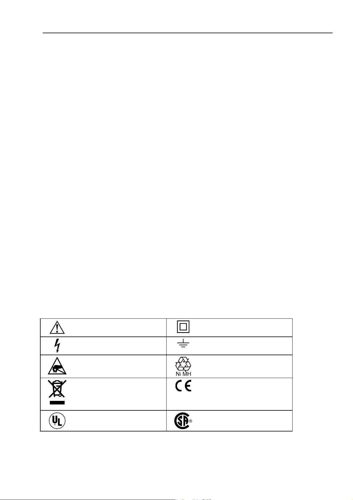
1.4 Symbols
The following symbols are used on the test tool, in the Users Manual, in this Service
Manual, or on spare parts for this test tool.
See explanation in Users Manual
Live voltage
Static sensitive components
(black/yellow).
Do not dispose of this product
as unsorted municipal waste. Go to
Fluke's website for recycling
information.
DOUBLE INSULATION (Protection
Class)
Earth Ground
Recycling information
Conformité Européenne
Safety Approval
1-3
Safety Approval
Page 12

Fluke 19xB-19xC-2x5C
Service Manual
1.5 Impaired Safety
Whenever it is likely that safety has been impaired, the test tool must be turned off and
disconnected from line power. The matter should then be referred to qualified
technicians. Safety is likely to be impaired if, for example, the test tool fails to perform
the intended measurements or shows visible damage.
1.6 General Safety Information
Removing the test tool covers or removing parts, except those
to which access can be gained by hand, is likely to expose live
parts and accessible terminals which can be dangerous to life.
The test tool shall be disconnected from all voltage sources before it is opened.
Capacitors inside the test tool can hold their charge even if the test tool has been
separated from all voltage sources.
When servicing the test tool, use only specified replacement parts.
Warning
1-4
Page 13

Chapter 2
Characteristics
For the specifications please refer to the ScopeMeter test tool Users
Manual Chapter “Specifications”.
2-1
Page 14

2-2
Page 15

Chapter 3
List of Replaceable Parts
Title Page
3.1 Introduction..................................................................................................3-3
3.2 How to Obtain Parts.....................................................................................3-3
3.3 Final Assembly Parts ...................................................................................3-4
3.4 Main PCA Unit Parts ...................................................................................3-6
3.5 Accessories ..................................................................................................3-8
3-1
Page 16

Page 17

List of Replaceable Parts
3.1 Introduction 3
3.1 Introduction
This chapter contains an illustrated list of replaceable parts for the ScopeMeter test tool.
Parts are listed by assembly; alphabetized by item number. Each assembly is
accompanied by an illustration showing the location of each part and its item number.
The parts list gives the following information:
• Item number
• Description
• Ordering code
3.2 How to Obtain Parts
Contact an authorized Fluke service center.
To locate an authorized service center refer to the second page of this manual (back of the
title page).
In the event that the part ordered has been replaced by a new or improved part, the
replacement will be accompanied by an explanatory note and installation instructions, if
necessary.
To ensure prompt delivery of the correct part, include the following information when
you place an order:
• Instrument model (for example Fluke-196C), 12 digit instrument code (9444 ... ....),
and serial number (DM.......). The items are printed on the type plate on the bottom
cover.
• Ordering code
• Item number
• Description
• Quantity
3-3
Page 18
Fluke 19xB-19xC-2x5C
Service Manual
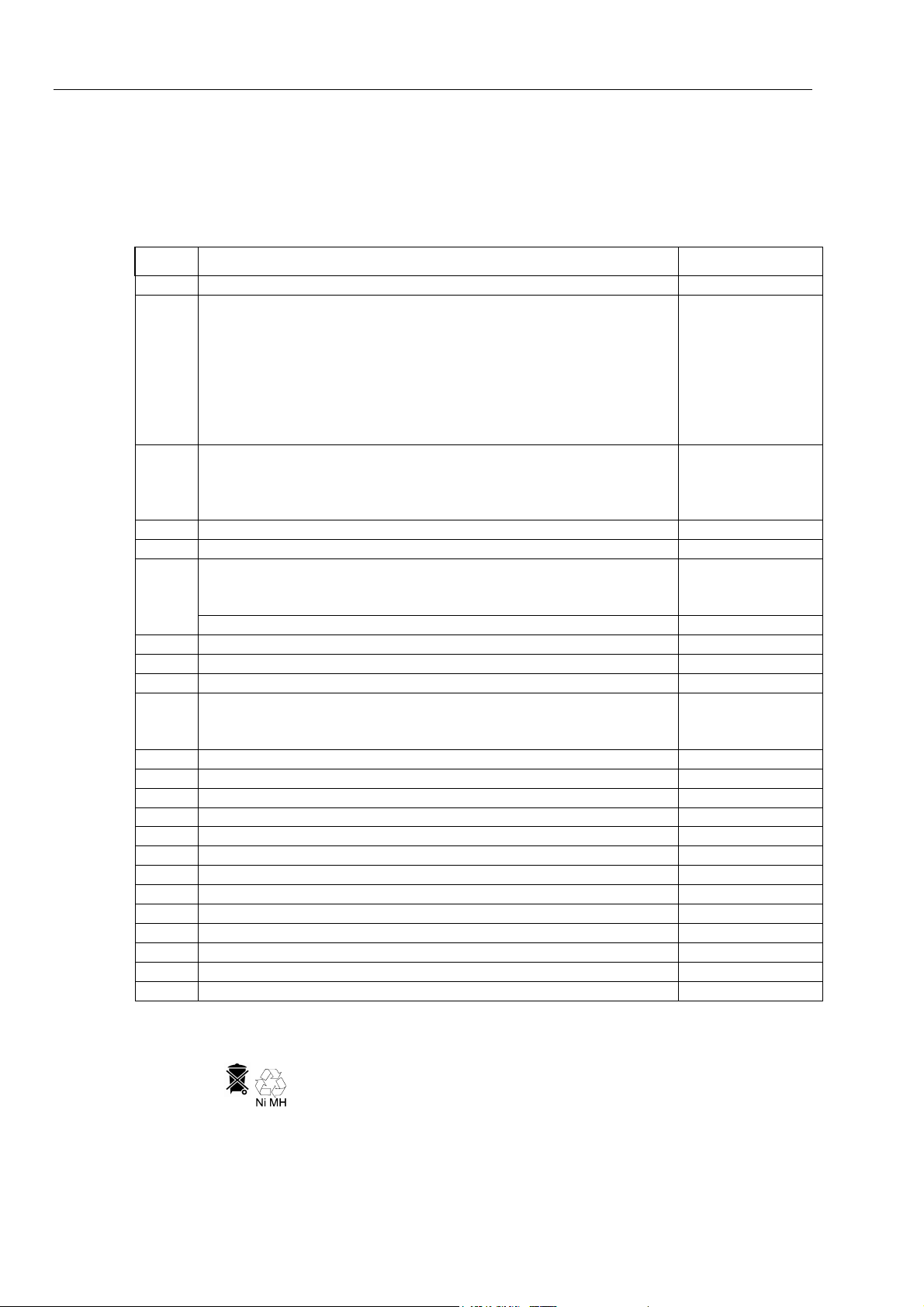
3.3 Final Assembly Parts
See Table 3-1 and Figure 3-1 for the Final Assembly parts.
Item Description Ordering Code
1 Top case assembly (without LCD, without window/decal) 1638248
2 Display window/decal Fluke 192B
Display window/decal Fluke 192C
Display window/decal Fluke 196B
Display window/decal Fluke 196C
Display window/decal Fluke 199B
Display window/decal Fluke 199C
Display window/decal Fluke 215C
Display window/decal Fluke 225C
3 + 4 Keypad set (includes large & small keypad) 19x
(Lowest yellow key = RECORDER)
Keypad set (includes large & small keypad) 2x5
(Lowest yellow key = ANALYZE)
5 Keypad foil 1642199
6 Keypad support assembly 1638253
7 Display unit Color Fluke 192C, 196C, 199C, 215C, 225C
Display unit B/W Fluke 192B, 196B, 199B
Remark: The Display unit does not include the flat cable
Flat cable for display unit (both versions) 2042596
8 Display mounting frame assy 1668063
9 Input cover (including screws) 1285765
10 EJOT Pt screw 1284966
11 Main PCA unit; The Main PCA is only available to Fluke Service Centers
due to the programming that is necessary after installation.
12 Hang strap 1286041
13 Bottom case assembly (see note 2 below) 1285783
14 Combi-screw Torx M3x10 (screw + split spring) 1285046
15 Strap 1285923
16 Strap holder 1285938
17 Tilt stand (bail) 1285945
18 Combi-screw Torx M3x10 (screw + flat washer) 1285079
19 Bottom holster 1285752
20 Combi-screw Torx M3x10 (screw + flat washer) 1285079
21 Battery Pack (see note 3 below) BP190
22 Spacer M2.5x3 for Fan 1638770
23 Fan Assy 1638294
24 Screw M2.5x12, countersunk Torx for Fan 1639787
Table 3-1. Final Assembly Parts
2042440
3402263
2042457
2042478
2042469
2042484
3402256
3402239
1638180
3402242
1638230
2042528
-
3-4
Note
The test tool contains a NiMH battery (item 21). Do not mix
with the solid wastestream. Spent batteries should be disposed
of by a qualified recycler or hazardous materials handler.
Page 19
List of Replaceable Parts
(2x)
3
4
5
6
7
3.3 Final Assembly Parts 3
1
2
9
21
20
(2x)
19
24
23
22
(2x)
(2x)
14
(2x)
18
Figure 3-1. Final Assembly Details
17
16
13
ST8738
10
11
12
15
8
(4x)
st8738.wmf
3-5
Page 20

Fluke 19xB-19xC-2x5C
Service Manual
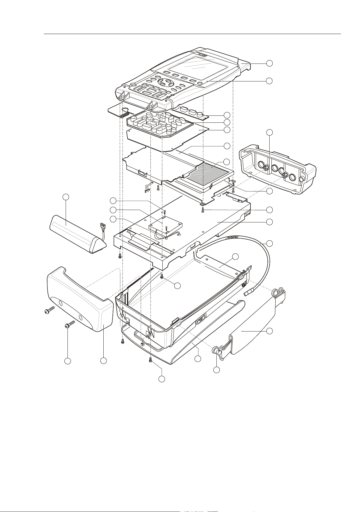
3.4 Main PCA Unit Parts
See Table 3-2 and Figure 3-2 for the main PCA Unit parts.
Item Description Ordering Code
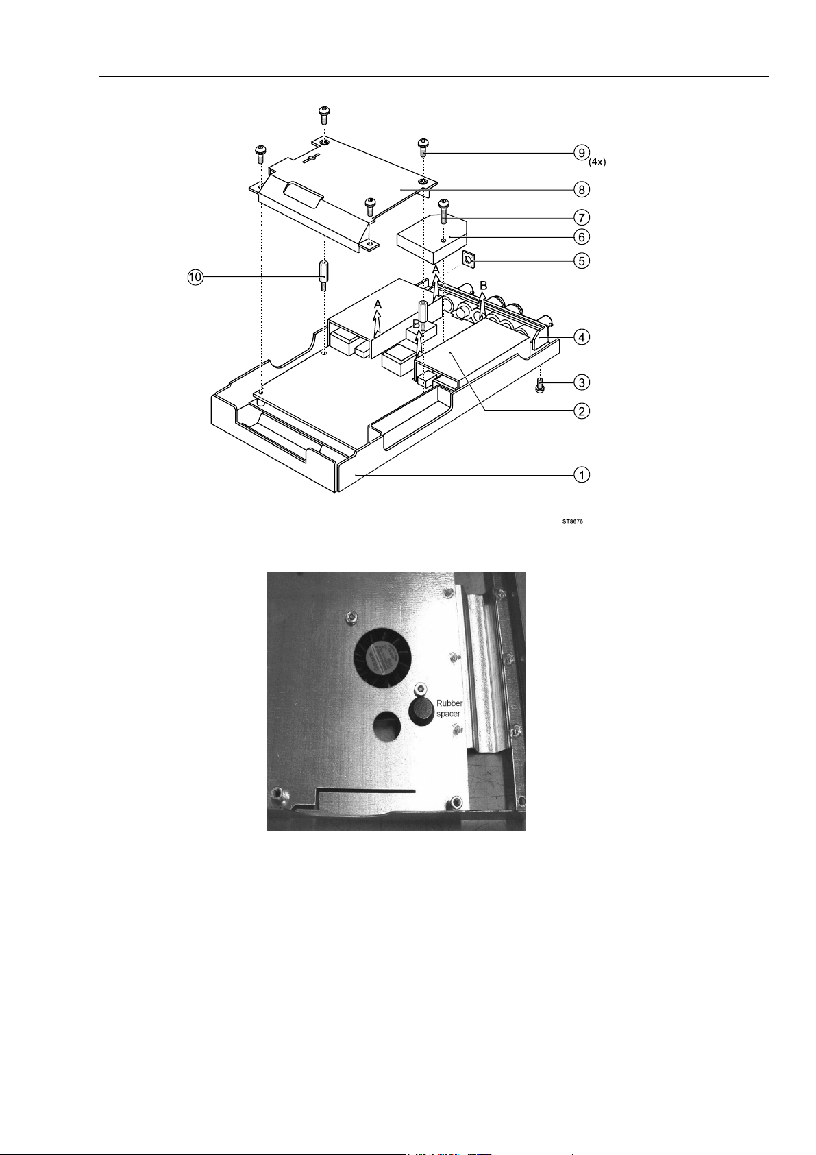
1 Shielding box assy (includes rubber spacer, see fig. 8-5) 1665767
2 Insulation foil 1285961
3 PT-Screw K35x8 1284975
4 Input connector unit 1285977
5 Sealing ring for power connector 1286052
6 Input attenuator shielding:
7 Screw Torx M3x20 1285101
8 Shielding cover 1286034
9 Combi-screw Torx M3x10 (screw + split spring) 1285046
10 Hexagonal spacer M3x16.5 1285199
Table 3-2. Main PCA Unit Parts
- METER channel top
- METER channel bottom
- SCOPE channel A top
- SCOPE channel B top
- SCOPE channel A&B bottom
1285989
1285992
1286007
1286018
1286029
Note
The Scope channel A and B input attenuator top shieldings are provided with a
plate spring. The spring end is provided with heat conducting tape; it contacts
the C-ASIC’s N1000 and N1200, and transports the heat from the C-ASIC to the
shielding.
Do not bend the springs, keep the tape on the spring end free of dust, and put the
shielding on the correct position.
3-6
Page 21
List of Replaceable Parts
3.4 Main PCA Unit Parts 3
Figure 3-2. Main PCA Unit
Figure 3-3. Rubber Spacer on Shielding Box Assy
ST8676.wmf
rubber-spacer-16gray.jpg
3-7
Page 22

Fluke 19xB-19xC-2x5C
Service Manual
3.5 Accessories
Battery Charger, available models:
Universal Europe 230 V, 50 and 60 Hz
North America 120 V, 50 and 60 Hz
United Kingdom 240 V, 50 and 60 Hz
Japan 100 V, 50 and 60 Hz
Australia 240 V, 50 and 60 Hz
Universal 115 V/230 V, 50 and 60 Hz
The universal adapter is standard equipped with a plug EN60320-2.2G. For
connection to the mains outlet use a line plug that complies with National
Standards. The 230V rating of the BC190/808 is not for use in North America.
Voltage Probe Set (Red), designed for use with the Fluke ScopeMeter 190 series
test tool. The set includes the following items (not available separately):
• 10:1 Voltage Probe (red)
• 4-mm Test Probe for Probe Tip (red)
• Hook Clip for Probe Tip (red)
• Ground Lead with Hook Clip (red)
• Ground Lead with Mini Alligator Clip (black)
• Ground Spring for Probe Tip (black)
Voltage Probe Set (Gray), designed for use with the Fluke ScopeMeter 190 series
test tool. The set includes the following items (not available separately):
• 10:1 Voltage Probe (gray)
• 4-mm Test Probe for Probe Tip (gray)
• Hook Clip for Probe Tip (gray)
• Ground Lead with Hook Clip (gray)
• Ground Lead with Mini Alligator Clip (black)
Test Lead Set TL75
Accessory Set (Red)
The set includes the following items (not available separately):
• Industrial Alligator for Probe Tip (red)
• 2-mm Test Probefor Probe Tip (red)
• Industrial Alligator for Banana Jack (red)
• 2-mm Test Probe for Banana Jack (red)
• Ground Lead with 4-mm Banana Jack (black)
Accessory Set (Gray)
The set includes the following items (not available separately):
• Industrial Alligator for Probe Tip (gray)
• 2-mm Test Probe for Probe Tip (gray)
• Industrial Alligator for Banana Jack (gray)
• 2-mm Test Probe for Banana Jack (gray)
• Ground Lead with 4-mm Banana Jack (black)
Replacement Set for Voltage Probe VP200
The set includes the following items (not available separately):
• 2x , 4-mm Test Probe for Probe Tip (red and gray)
• 3x , Hook Clip for Probe Tip (2 red, 1 gray)
• 2x , Ground Lead with Hook Clip (red and gray)
• 2x , Ground Lead with Mini Alligator Clip (black)
• 5x Ground Spring for Probe Tip (black)
Table 3-3. Standard Accessories
Item Ordering Code
BC190/801
BC190/813
BC190/804
BC190/806
BC190/807
BC190/808
VP210-R
See Note below
VP210-G
See Note below
AS200-R
AS200-G
RS200
3-8
Page 23

List of Replaceable Parts
3.5 Accessories 3
Note:
From May 2007 the VPS200 probe sets have been replaced with the
VPS210 probe sets. The specifications of the VPS210 and the VPS200
probes are identical. The AS200 accessory sets can be used for the VP200
as well as for the VPS210 probe sets.
Table 3-4. Optional Accessories
Item Ordering Code
Software & Cable Carrying Case Kit
Set contains the following parts:
• Optically Isolated USB Cable
• Hard Carrying Case
• FlukeView™ ScopeMeter Software for Windows®
Optically Isolated RS-232 Adapter/Cable PM9080
Optically Isolated USB Cable OC4USB
Hard Case C190
Soft Case C195
Current Shunt 4-20 mA CS20MA
Print Adapter Cable for Parallel Printers PAC91
Bus Health Test Adapter (for Fluke 215C-225C) BHT190
SCC190
OC4USB
C190
SW90W
3-9
Page 24

Fluke 19xB-19xC-2x5C
Service Manual
3-10
Page 25

Chapter 4
Performance Verification
Title Page
4.1 Introduction.................................................................................................. 4-3
4.2 Equipment Required For Verification ......................................................... 4-3
4.3 General Instructions..................................................................................... 4-3
4.4 Operating Instructions.................................................................................. 4-4
4.4.1 Resetting the test tool ........................................................................... 4-4
4.4.2 Navigating through menu’s .................................................................. 4-4
4.4.3 Creating Test Tool Setup1.................................................................... 4-5
4.5 Display and Backlight Test.......................................................................... 4-5
4.6 Scope Input A&B Tests ............................................................................... 4-7
4.6.1 Input A&B Vertical Accuracy Test ...................................................... 4-7
4.6.2 Input A&B DC Voltage Accuracy Test................................................ 4-9
4.6.3 Input A&B AC Voltage Accuracy Test (LF) ....................................... 4-11
4.6.4 Input A & B AC Coupled Lower Frequency Test............................... 4-12
4.6.5 Input A and B Peak Measurements Test.............................................. 4-13
4.6.6 Input A&B Frequency Measurement Accuracy Test ........................... 4-14
4.6.7 Input A&B Phase Measurements Test.................................................. 4-15
4.6.8 Time Base Test ..................................................................................... 4-16
4.6.9 Input A Trigger Sensitivity Test........................................................... 4-17
4.6.10 Input A AC Voltage Accuracy (HF) & Bandwidth Test .................... 4-19
4.6.11 Input B Trigger Sensitivity Test ......................................................... 4-20
4.6.12 Input B AC Voltage Accuracy (HF) & Bandwidth Test .................... 4-21
4.6.13 Video test using the Video Pattern Generator .................................... 4-22
4.6.14 Video test using SC600 Scope Calibration Option ............................ 4-24
4.7 External Trigger Level Test ......................................................................... 4-27
4.8 Meter (DMM) Tests..................................................................................... 4-28
4.8.1 Meter DC Voltage Accuracy Test ........................................................ 4-28
4.8.2 Meter AC Voltage Accuracy & Frequency Response Test ................. 4-29
4.8.3 Continuity Function Test...................................................................... 4-30
4.8.4 Diode Test Function Test ..................................................................... 4-30
4.8.5 Ohms Measurements Test .................................................................... 4-30
4.9 Probe Calibration Generator Test ................................................................ 4-32
4-1
Page 26

Fluke 19xB-19xC-2x5C
Service Manual
4-2
Page 27

Performance Verification
4.1 Introduction 4
4.1 Introduction
Warning
Procedures in this chapter should be performed by qualified
service personnel only. To avoid electrical shock, do not
perform any servicing unless you are qualified to do so.
The ScopeMeter® test tool (referred to as test tool) should be calibrated and in operating
condition when you receive it.
The following performance tests are provided to ensure that the test tool is in a proper
operating condition. If the test tool fails any of the performance tests, calibration
adjustment (see Chapter 5) and/or repair is necessary.
The Performance Verification Procedure is based on the specifications, see Chapter 2 of
this Service Manual. The values given here are valid for ambient temperatures between
18 °C and 28 °C.
The Performance Verification Procedure is a quick way to check most of the test tool’s
specifications. Because of the highly integrated design of the test tool, it is not always
necessary to check all features separately.
4.2 Equipment Required For Verification
The primary source instrument used in the verification procedures is the Fluke 5500A. If
a 5500A is not available, you can substitute another calibrator as long as it meets the
minimum test requirements.
• Fluke 5500A Multi Product Calibrator, including SC300 or SC600 Oscilloscope
Calibration Option.
• Stackable Test Leads (4x), supplied with the 5500A.
• 50Ω Coax Cables (2x), Fluke PM9091 (1.5m) or PM9092 (0.5m).
• Male BNC to Dual Female BNC adapter (1x), Fluke PM9093/001
• 50Ω feed through termination, Fluke PM9585.
• Dual Banana Plug to Female BNC Adapter (1x), Fluke PM9081/001.
• Dual Banana Jack to Male BNC Adapter (1x), Fluke PM9082/001.
• TV Signal Generator, Philips PM5418, NOT required if SC600 Oscilloscope
Calibration Option is used.
• 75Ω Coax cable (1x), Fluke PM9075.
• 75Ω Feed through termination (1x), ITT-Pomona model 4119-75.
4.3 General Instructions
Follow these general instructions for all tests:
• For all tests, power the test tool with the BC190 power adapter/battery charger. The
battery pack must be installed.
• Allow the 5500A to satisfy its specified warm-up period.
• For each test point , wait for the 5500A to settle.
• Allow the test tool a minimum of 30 minutes to warm up.
• One division on the LCD consists of 25 pixels ( 1 pixel = 0.04 division).
4-3
Page 28

Fluke 19xB-19xC-2x5C
Service Manual
4.4 Operating Instructions
4.4.1 Resetting the test tool
Proceed as follows to reset the test tool:
• Press
• Press and hold
• Press and release
to turn the test tool off.
.
to turn the test tool on.
• Wait until the test tool has beeped twice, and then release
has beeped twice, the RESET was successful.
4.4.2 Navigating through menu’s
During verification you must open menus, and to choose items from the menu.
Proceed as follows to make choices in a menu :
• Reset the test tool
• Open a menu, for example press
as showed in Figure 4-1 will be opened.
Active functions are marked by
If more than one menu groups are available, they will be separated by a vertical line.
The menu you opened indicates that
shows the result of a V ac+dc measurement (
• Press
• Press
or to highlight the function to be selected.
(ENTER) to confirm the selection.
The active function in the next menu group will be highlighted now. If the
confirmation was made in the last (most right) menu group, the menu will be closed.
, then press (READING 1). The menu
,inactive functions by .
READING 1 (that is the upper left reading)
V ac+dc ) on Input A ( on A ).
.. When the test tool
4-4
Figure 4-1. Menu item selection
ws-read1.bmp
Page 29

Performance Verification
4.5 Display and Backlight Test 4
4.4.3 Creating Test Tool Setup1
Before starting the verification procedure you must define a standard test tool setup,
called SETUP 1. During verification you will be asked to recall this setup. This defines
the initial test tool setup for each verification.
Proceed as follows to create SETUP1:
1. Reset the test tool. Input A is ON, Input B is OFF now.
2. Press
3. Press
. The inverse text indicates the actual settings.
(toggle key) to select INPUT B ON. The Input B trace will become
visible.
4. Press
5. Select
6. Press
7. Press
8. Select
9. Press
10. Press
11. Press
12. Press
13. Press
Glitch Detect: Off | Average: Off | Waveform: NORMAL
14. Press
to change the PROBE B setting.
Probe Type: Voltage | Attenuation: 1:1 .
. The inverse text indicates the actual settings.
to change the PROBE A setting.
Probe Type: Voltage | Attenuation: 1:1 .
to select READINGS ON
READING 1 , and select on A | V dc
READING 2 , and select on B | V dc
WAVEFORM OPTIONS and select
to select MANUAL ranging (MANUAL in upper left of screen)
15. Press
16. Press
17. Using
18. Press
19. Press
SAVE...
and select SCREEN+SETUP 1 (or 1).
SAVE to save the actual test tool settings in setup memory 1.
to leave the HOLD mode.
4.5 Display and Backlight Test
Proceed as follows to test the display and the backlight:
1. Press
2. Remove the BC190 adapter power, and verify that the backlight is dimmed.
3. Apply the BC190 adapter power and verify that the backlight brightness increases.
4. Press and hold
4-5
to turn the test tool on.
(USER), then press and release (CLEAR MENU)
Page 30

Fluke 19xB-19xC-2x5C
Service Manual
The test tool shows the calibration menu in the bottom of the display.
• Do not press
• Pressing
5. Press
The test tool shows
6. Press
PREVIOUS three times.
CALIBRATE .The test tool shows a dark display; the test pattern as
now! If you did, turn the test tool off and on, and start at 4.
will toggle the menu on-off.
Contrast (CL 0100):
shown in Figure 4-2 may be not visible or hardly visible.
Observe the display closely, and verify that the display shows no abnormalities, as
for example very light pixels or lines.
Figure 4-2. Display Test Pattern
7. Press .
The test pattern is removed; the test tool shows
Contrast (CL 0100):
8. Press
9. Press
again to do the next step Contrast (CL 0110):
CALIBRATE
The test tool shows the display test pattern shown in Figure 4-2, at default contrast.
Observe the display closely, and verify that the display shows no abnormalities. Also
verify that the contrast of the upper left and upper right square of the test pattern is
equal.
10. Press
The test pattern is removed; the test tool shows
11. Press
12. Press
.
Contrast (CL 0110):
again to do the next step Contrast (CL 0120):
CALIBRATE
The test tool shows a light display; the test pattern as shown in Figure 4-2 may not be
visible or hardly visible.
Observe the display closely, and verify that the display shows no abnormalities.
13. Turn the test tool OFF and ON to exit the calibration menu and to return to the
normal operating mode.
If the maximum, minimum, or default display contrast is not OK, then you can set these
items without performing a complete calibration adjustment; refer to Section 5 for
detailed information.
4-6
Page 31

Performance Verification
4.6 Scope Input A&B Tests 4
4.6 Scope Input A&B Tests
4.6.1 Input A&B Vertical Accuracy Test
WARNING
Dangerous voltages will be present on the calibration source
and connecting cables during the following steps. Ensure that
the calibrator is in standby mode before making any connection
between the calibrator and the test tool.
Proceed as follows:
1. Connect the test tool to the 5500A as shown in Figure 4-3.
Figure 4-3. Test Tool Input A&B to 5500 Normal Output
al55ab.bmp
2. Select the following test tool setup:
• Recall the created SETUP 1 (see section 4.4.3): press
select
• Press
Bandwidth:
• Press
Bandwidth:
• Press
SCREEN+SETUP 1 , press
, press INPUT A OPTIONS... , and select Polarity Normal |
10 kHz (HF reject)
, press INPUT B OPTIONS... , and select Polarity Normal |
10 kHz (HF reject)
to clear the softkey menu, and to see the full screen.
RECALL SETUP .
,
RECALL ,
Note:
The 10 kHz bandwidth limiter rejects calibrator noise. It does not affect the gain
accuracy at a 50 Hz input signal
3. Using
change the time base to select manual time base ranging, and lock the
time base on 10 ms/div.
4-7
Page 32

Fluke 19xB-19xC-2x5C
Service Manual
4. Using and move the Input A ground level (indicated by the zero icon in
the left margin) to the center grid line.
5. Using
and move the Input B ground level (indicated by the zero icon in
the left margin) to the grid line one division below the center grid line.
6. Using
and set the Input A and B sensitivity range to the first test point in
Table 4-1.
7. Set the 5500A to source the appropriate initial ac voltage.
8. Adjust the 5500A output voltage until the displayed Input A trace amplitude is 6
divisions.
9. Observe the 5500A output voltage and check to see if it is within the range shown
under the appropriate column.
10. Adjust the 5500A output voltage until the displayed Input B trace amplitude is 6
divisions.
11. Observe the 5500A output voltage and check to see if it is within the range shown
under the appropriate column.
12. Continue through the test points.
13. When you are finished, set the 5500A to 0 (zero) Volt, and to Standby.
Table 4-1. Vertical Accuracy Verification Points
Range Initial 5500A Setting,
V ac, sine, 50 Hz
Allowable 5500A output for trace amplitude of
6 divisions
2 mV/div 1) 4.243 mV 4.081 to 4.405
5 mV/div 10.606 mV 10.247 to 10.966
10 mV/div 21.213 mV 20.495 to 21.932
20 mV/div 42.426 mV 40.990 to 43.862
50 mV/div 106.06 mV 102.475 to 109.657
100 mV/div 212.13 mV 204.950 to 219.314
200 mV/div 424.26 mV 409.90 to 438.62
500 mV/div 1.0607 V 1.02475 to 1.09657
1 V/div 2.1213 V 2.04950 to 2.19314
2 V/div 4.2426 V 4.0990 to 4.3862
5 V/div 10.606 V 10.2475 to 10.9657
10 V/div 21.213 V 20.4950 to 21.9314
20 V/div 42.426 V 40.990 to 43.862
50 V/div 106.06 V 102.47 to 109.65
100 V/div 212.13 V 204.95 to 219.31
1)
C versions only
4-8
Page 33

Performance Verification
4.6 Scope Input A&B Tests 4
Note
The vertical accuracy test can also be done with dc voltage. This method is
advised for automatic verification using the Fluke Met/Cal Metrology
Software. For each sensitivity range you must proceed as follows:
1. Apply a +3 divisions voltage, and adjust the voltage until the trace is at
+3 divisions. Write down the applied voltage V1
2. Apply a -3 divisions voltage, and adjust the voltage until the trace is at
-3 divisions. Write down the applied voltage V2
3. Verify that V1-V2 = 6 x range
±
(1.5% + 0.04 x range).:
Example for range 10 mV/div. (range/div figure doubles because 2
measurements V1 and V2 are done for one accuracy check):
±
The allowed V1 - V2 = 60 mV
= 60 mV
(0.015 x 60 + 0.08 x 10)
±
(0.9 + 0.8) = 60 mV ± 1.7 mV
4.6.2 Input A&B DC Voltage Accuracy Test
WARNING
Dangerous voltages will be present on the calibration source
and connecting cables during the following steps. Ensure that
the calibrator is in standby mode before making any connection
between the calibrator and the test tool.
Proceed as follows to verify the automatic dc voltage scope measurement:
1. Connect the test tool to the 5500A as for the previous test (see Figure 4-3).
2. Select the following test tool setup:
• Recall the created SETUP 1 (see section 4.4.3): press
select
SCREEN+SETUP 1 , press RECALL SETUP .
• Press
• Select
• Press
, then press INPUT A OPTIONS ...
Polarity: Normal | Bandwidth: 10 kHz (HF Reject)
, then press INPUT B OPTIONS ...
, RECALL ,
• Select Polarity: Normal | Bandwidth: 10 kHz (HF Reject)
• Press
3. Using
to clear the softkey menu, and to see the full 8 divisions screen.
change the time base to select manual time base ranging, and lock the
time base on 10 ms/div.
4. Using
and move the Input A and B ground level (zero icon in the left
margin) approximately to the center grid line.
5. Using
and select manual vertical ranging and set the Input A and B
sensitivity range to the first test point in Table 4-2.
The sensitivity ranges are indicated in the left and right lower display edge.
6. Set the 5500A to source the appropriate dc voltage.
7. Observe the readings (
1.A and 2.B) and check to see if it is within the range shown
under the appropriate column.
Due to calibrator noise, occasionally OL (overload) can be shown.
8. Continue through the test points.
9. When you are finished, set the 5500A to 0 (zero) Volt, and to Standby.
4-9
Page 34

Fluke 19xB-19xC-2x5C
Service Manual
2 mV/div 1) +6.0 mV +4.9 to +7.1
10 mV/div +30.0 mV +29.1 to +30.9
20 mV/div +60.0 mV +58.6 to +61.4
50 mV/div +150 mV +143 to +157
100 mV/div +300 mV +291 to +309
Table 4-2. Volts DC Measurement Verification Points
Range 5500A output V dc Input A&B Reading
-6.0 mV -4.9 to -7.1
5 mV/div +15.0 mV +14.3 to +15.7
-15.0 mV -14.3 to -15.7
-30.0 mV -29.1 to -30.9
-60.0 mV -58.6 to -61.4
-150 mV -143 to -157
-300 mV -291 to -309
200 mV/div +600 mV +586 to +614
-600 mV -586 to -614
500 mV/div +1.50 V +1.43 to +1.57
-1.50 V -1.43 to -1.57
1 V/div +3.00 V +2.91 to +3.09
-3.00 V -2.91 to -3.09
2 V/div +6.00 V +5.86 to +6.14
-6.00 V -5.86 to -6.14
5 V/div +15.0 V +14.3 to +15.7
-15.0 V -14.3 to -15.7
10 V/div +30.0 V +29.1 to +30.9
-30.0 V -29.1 to -30.9
20 V/div +60.0 V +58.6 to +61.4
-60.0 V -58.6 to -61.4
50 V/div +150 V +143 to +157
4-10
100 V/div +300 V +291 to +309
1)
C versions only.
-150 V -143 to -157
-300 V -291 to -309
Page 35

Performance Verification
4.6 Scope Input A&B Tests 4
4.6.3 Input A&B AC Voltage Accuracy Test (LF)
This procedure tests the Volts ac accuracy with dc coupled inputs up to 50 kHz. The
high frequencies are tested in sections 4.6.10 and 4.6.12.
Warning
Dangerous voltages will be present on the calibration source
and connecting cables during the following steps. Ensure that
the calibrator is in standby mode before making any connection
between the calibrator and the test tool.
Proceed as follows to test the Input A and B automatic scope ac Voltage measurement
accuracy:
1. Connect the test tool to the 5500A as for the previous test (see Figure 4-3).
2. Select the following test tool setup:
• Recall the created SETUP 1 (see section 4.4.3): press
SCREEN+SETUP 1 , press RECALL SETUP .
select
• Press
• Select
• Press
• Select
• Press
• Press
• Press
• Press
3. Using
, then press INPUT A OPTIONS ...
Polarity: Normal | Bandwidth: 20 MHz
, then press INPUT B OPTIONS ...
Polarity: Normal | Bandwidth: 20 MHz
READING 1 , and select on A | V ac.
READING 2 , and select on B | V ac.
to clear the softkey menu, and to see the full screen.
change the time base to select manual time base ranging. Lock the
, RECALL ,
time base on 20 μs/div for the 20 kHz signals, and on 10 ms/div for the 60 Hz signal.
4. Using
5. Using
and move the Input A and B ground level (indicated by the zero icon
in the left margin) to the center grid line.
and select manual vertical ranging, and set the Input A and B
sensitivity range to the first test point in Table 4-3.
The sensitivity ranges are indicated in the left and right lower display edge in gray.
6. Set the 5500A to source the appropriate ac voltage.
7. Observe the readings (
1.A and 2.B) and check to see if it is within the range shown
under the appropriate column.
8. Continue through the test points.
9. When you are finished, set the 5500A to 0 (zero) Volt, and to Standby.
4-11
Page 36

Fluke 19xB-19xC-2x5C
Service Manual
Table 4-3. Volts AC Measurement Verification Points
Range 5500A output Input A&B Reading
V ac Frequency
2 mV/div 1) (Select 10 ms/div)
Set input A&B Bandwidth 10 kHz
to prevent OL due to calibrator
noise: see step 2.
5 mV/div (Select 20 μs/div).
Set input A&B Bandwidth 20 MHz
10 mV/div 20 mV 20 kHz 18.0 mV to 22.0 mV
20 mV/div 40 mV 20 kHz 37.5 mV to 42.5 mV
50 mV/div 100 mV 20 kHz 96.0 mV to 104.0 mV
100 mV/div 200 mV 20 kHz 180 mV to 220 mV
200 mV/div 400 mV 20 kHz 375 mV to 425 mV
500 mV/div (Select 10 ms/div) 900 mV 60 Hz 877 mV to 923 mV
500 mV/div (Select 20 μs/div) 900 mV 20 kHz 863 mV to 937 mV
1 V/div 2 V 20 kHz 1.80 V to 2.20 V
2 V/div 4 V 20 kHz 3.75 V to 4.25 V
5 V/div 9 V 20 kHz 8.63 V to 9.37 V
10 V/div 20 V 20 kHz 18.0 V to 22.0 V
4 mV 60 Hz 3.0 mV to 5.0 mV
10 mV 20 kHz 8.3 mV to 11.7 mV
20 V/div 40 V 20 kHz 37.5 V to 42.5 V
50 V/div 90 V 20 kHz 86.3 V to 93.7 V
100 V/div 200 V 20 kHz 180 V to 220 V
1)
C versions only
4.6.4 Input A & B AC Coupled Lower Frequency Test
Proceed as follows to test the ac coupled input low frequency accuracy:
1. Connect the test tool to the 5500A as for the previous test (see Figure 4-3).
2. Select the following test tool setup:
• Recall the created SETUP 1 (see section 4.4.3): press
select
SCREEN+SETUP 1 , press RECALL SETUP .
• Press
• Press
• Press
• Press
• Press
READING 1 , and select on A | V ac.
READING 2 , and select on B | V ac.
, then using select COUPLING AC
, then using select COUPLING AC
, RECALL ,
4-12
Page 37

Performance Verification
4.6 Scope Input A&B Tests 4
• Press to clear the softkey menu, and to see the full screen.
3. Using
change the time base to select manual time base ranging, and lock the
time base on 50 ms/div.
4. Using
5. Using
and move the Input A and B ground level (indicated by the zero icon
in the left margin) to the center grid line.
and select manual vertical ranging, and set the Input A and B
sensitivity range to 500 mV.
6. Set the 5500A to source the appropriate ac voltage and frequency, according to
Table 4-4.
7. Observe the readings (
1.A and 2.B) and check to see if it is within the range shown
under the appropriate column.
8. Continue through the test points.
9. When you are finished, set the 5500A to 0 (zero) Volt, and to Standby.
Table 4-4. Input A&B AC Input Coupling Verification Points
5500A output, V rms 5500A Frequency Reading 1.A and 1.B
900 mV 60 Hz 873 mV to 927 mV
900 mV 5 Hz >630 mV
4.6.5 Input A and B Peak Measurements Test
WARNING
Dangerous voltages will be present on the calibration source
and connecting cables during the following steps. Ensure that
the calibrator is in standby mode before making any connection
between the calibrator and the test tool.
Proceed as follows to test the Peak measurement accuracy:
1. Connect the test tool to the 5500A as for the previous test (see Figure 4-3).
2. Select the following test tool setup:
• Recall the created SETUP 1 (see section 4.4.3): press
select
SCREEN+SETUP 1 , press RECALL SETUP .
• Press
• Press
Select
• Press
Select
• Press
READING 1 , and select on A | Peak.
Peak-Peak from the Peak menu.
READING 2 , and select on B | Peak.
Peak-Peak from the Peak menu.
to clear the softkey menu, and to see the full screen.
, RECALL ,
3. Using
change the time base to select manual time base ranging, and lock the
time base on 1 ms/div.
4-13
Page 38

Fluke 19xB-19xC-2x5C
Service Manual
4. Using and move the Input A and B ground level (indicated by the zero icon
in the left margin) to the center grid line.
5. Using
and select manual vertical ranging, and set the Input A and B
sensitivity range to 100 mV.
6. Set the 5500A to source the appropriate ac voltage and frequency, according to
Table 4-5.
7. Observe the readings (
1.A and 2.B) and check to see if it is within the range shown
under the appropriate column.
8. Continue through the test points.
9. When you are finished, set the 5500A to 0 (zero) Volt, and to Standby.
Table 4-5. Volts Peak Measurement Verification Points
5500A output, Vrms (sine) 5500A Frequency Reading A-B
212.13 mV (0.6 V pp) 1 kHz 0.56 to 0.64
4.6.6 Input A&B Frequency Measurement Accuracy Test
Proceed as follows to test the frequency measurement accuracy:
1. Connect the test tool to the 5500A as shown in Figure 4-4. Do NOT use 50 Ω
terminations!
4-14
Figure 4-4. 5500 Scope Output to Test Tool Input A&B
2. Select the following test tool setup:
• Recall the created SETUP 1 (see section 4.4.3): press
select
SCREEN+SETUP 1 , press RECALL SETUP .
• Press
al55scab.bmp
, RECALL ,
Page 39

Performance Verification
4.6 Scope Input A&B Tests 4
• Press READING 1 , and select on A | Hz.
• Press
3. Using
4. Using
READING 2 , and select on B | Hz.
and select range 100 mV/div for A and B.
select the required time base setting.
5. Set the 5500A to source a sine wave according to the first test point in Table 4-6.
As no 50Ω termination is applied, the 5500 leveled sine wave output amplitude will
be twice the set value.
6. Observe the readings (
1.A and 2.B) and check to see if it is within the range shown
under the appropriate column.
7. Continue through the test points.
8. When you are finished, set the 5500A to 0 (zero) Volt, and to Standby.
Table 4-6. Input A&B Frequency Measurement Accuracy Test
Model Time base 5500A-SC... MODE Voltage Frequency Input A&B Reading
all 20 ms/div wavegen, sine 600 mVpp 16 Hz 15.90 to 16.10
192B-C 20 ns/div levsine 300 mVpp 60 MHz 59.68 to 60.32
196B-C, 215C 20 ns/div levsine 300 mVpp 100 MHz 99.3 to 100.7
199B-C, 225C 20 ns/div levsine 300 mVpp 200 MHz 198.8 to 201.2
Note
Duty Cycle and Pulse Width measurements are based on the same
principles as Frequency measurements. Therefore the Duty Cycle and
Pulse Width measurement function will not be verified separately.
4.6.7 Input A&B Phase Measurements Test
Proceed as follows to test the phase measurement accuracy:
1. Connect the test tool to the 5500A as for the previous test (see Figure 4-4).
2. Select the following test tool setup:
• Recall the created SETUP 1 (see section 4.4.3): press
select
SCREEN+SETUP 1 , press RECALL SETUP .
• Press
• Press
• Press
3. Using
and select range 100 mV/div for A and B.
4. Using
5. Set the 5500A to source a sine wave according to the first test point in Table 4-6.
As no 50Ω termination is applied, the 5500 leveled sine wave output amplitude will
be twice the set value.
READING 1 , and select on A | Phase.
READING 2 , and select on B | Phase.
select the required time base setting.
, RECALL ,
4-15
Page 40

Fluke 19xB-19xC-2x5C
Service Manual
6. Observe the reading 1.A and 2.B and check to see if they are not outside the range
7. Continue through the test points.
8. When you are finished, set the 5500A to 0 (zero) Volt, and to Standby.
Time base 5500A-SC... MODE Frequency Voltage Input A&B Reading ...Deg
20 ms/div wavegen, sine, 1 MΩ 10 Hz 600 mVpp -2 to +2
200 ns/div levsine 1 MHz 300 mVpp -2 to +2
20 ns/div levsine 10 MHz 300 mVpp -3 to +3
4.6.8 Time Base Test
Proceed as follows to test the time base accuracy:
1. Connect the test tool to the 5500A as shown in Figure 4-5.
shown under the appropriate column.
Table 4-7. Phase Measurement Verification Points
4-16
Figure 4-5. 5500A Scope Output to Test Tool Input A
2. Set the 5500A to source a 8 ms time marker (MODE marker).
3. Select the following test tool setup:
• Reset the test tool
• Using
and select manual vertical ranging, and set the Input A sensitivity
range to 5V (probe A is 10:1, so input sensitivity is 500 mV/div).
• Using
change the time base to select manual time base ranging, and lock
the time base on 10 ms/div).
• Using
move the trace to the left. After moving the trace 2 divisions, the
trigger delay time with respect to the first vertical grid line will be indicated in
al55sca.bmp
Page 41

Performance Verification
4.6 Scope Input A&B Tests 4
the center of the display bottom.
Adjust the trigger delay time to 8.000 ms (
A →| 8.00 ms )
• Using
4. Using
set the time base on 10 μs/div.
move the trace to the right until the indicated trigger delay is
7.990 ms.
5. Examine the rising edge of the time marker pulse at the height of the trigger level
indicator top. Verify that the rising edge is at the second grid line from the left. The
allowed deviation is ±3 pixels, see Figure 4-6.
6. Select the following test tool setup:
• Using
change the time base to select manual time base ranging, and lock
the time base on 10 ms/div).
• Using
A 800.0 μs).
(
• Using
move the trace to adjust the trigger delay time to 800.0 μs
set the time base on 1 μs/div.
7. Set the 5500A to source a 0.8 ms time marker (MODE marker).
8. Using
move the trace to the right until the indicated trigger delay is
799.0 μs.
9. Examine the rising edge of the time marker pulse at the vertical height of the trigger
level indicator top. Verify that the rising edge is at the second grid line from the left.
The allowed deviation is ±3 pixels, see Figure 4-6.
Figure 4-6. Time Base Verification
190c-tb1.bmp
4.6.9 Input A Trigger Sensitivity Test
Proceed as follows to test the Input A trigger sensitivity:
1. Connect the test tool to the 5500A as for the previous test (see Figure 4-5).
2. Select the following test tool setup:
• Reset the test tool
4-17
Page 42

Fluke 19xB-19xC-2x5C
Service Manual
• Using and change the sensitivity range to select manual sensitivity
ranging, and lock the Input A sensitivity range on 2 V/div.
3. Using
select the time base indicated under the second column of Table 4-8.
4. Set the 5500A to source the leveled sine wave for the appropriate test tool model.
5. Adjust the 5500A output voltage until the displayed trace has the trigger amplitude
indicated under the last column of Table 4-8.
6. Verify that the signal is well triggered.
If it is not, press
, then using enable the up/down arrow keys for manual
Trigger Level adjustment. Adjust the trigger level and verify that the signal will be
triggered now. The trigger level is indicated by the trigger icon (
).
7. Continue through the test points.
8. When you are finished, set the 5500A to Standby.
Table 4-8. Input A Trigger Sensitivity Test Points
UUT UUT 5500A SC... MODE levsin UUT
Model Time base Initial Input Voltage Frequency Trigger Amplitude
ALL 200 ns/div 100 mV pp 5 MHz 0.5 div
192B-C 10 ns/div 400 mV pp 60 MHz 1 div
10 ns/div 800 mV pp 100 MHz 2 div
196B-C, 215C 10 ns/div 400 mV pp 100 MHz 1 div
10 ns/div 800 mV pp 150 MHz 2 div
199B-C, 225C 10 ns/div 400 mV pp 200 MHz 1 div
10 ns/div 800 mV pp 250 MHz 2 div
4-18
Page 43

Performance Verification
4.6 Scope Input A&B Tests 4
4.6.10 Input A AC Voltage Accuracy (HF) & Bandwidth Test
Proceed as follows to test the Input A high frequency automatic scope ac voltage
measurement accuracy, and the bandwidth:
1. Connect the test tool to the 5500A as for the previous test (see Figure 4-5).
2. Select the following test tool setup:
• Recall the created SETUP 1 (see section 4.4.3): press
select
SCREEN+SETUP 1 , press RECALL SETUP .
• Press
• Press
• Using
, then press READING 1 , and select on A | V ac.
to select autoranging (AUTO in upper right LCD edge)
and change the sensitivity range to select manual sensitivity
ranging, and lock the Input A sensitivity range on 500 mV/div. (
, RECALL ,
AUTO in upper
right LCD edge disappears)
3. Set the 5500A to source a sine wave, to the first test point in Table 4-9.
4. Observe the Input A reading and check to see if it is within the range shown under
the appropriate column.
5. Continue through the test points.
6. When you are finished, set the 5500A to Standby.
Table 4-9. HF AC Voltage Verification Points
UUT 5500A SC... MODE levsin UUT
Model Voltage Frequency Reading A
all 2.545 Vpp 1 MHz 835 mV to 965 mV
all 2.545 Vpp 25 MHz 790 mV to 1.010 V
192B-C 2.545 Vpp 60 MHz >630 mV
196B-C, 215C 2.545 Vpp 100 MHz >630 mV
199B-C, 225C 2.545 Vpp 200 MHz >630 mV
4-19
Page 44

Fluke 19xB-19xC-2x5C
Service Manual
4.6.11 Input B Trigger Sensitivity Test
Proceed as follows to test the Input B trigger sensitivity:
1. Connect the test tool to the 5500A as shown in Figure 4-7.
Figure 4-7. 5500A Scope Output to Test Tool Input B
al55scb.bmp
2. Select the following test tool setup:
• Reset the test tool
• Press
• Press
• Using
• Press
• Using
and use to turn Input B on.
and use to turn Input A off.
move the Input B trace zero to the center grid line.
and use to select Input B as trigger source.
and change the sensitivity range to select manual sensitivity
ranging, and lock the Input B sensitivity range on 2 V/div.
3. Using
select the time base indicated under the first column of Table 4-10.
4. Set the 5500A to source the leveled sine wave given in the first row of Table 4-10.
5. Adjust the 5500A output voltage until the displayed trace has the amplitude indicated
under the appropriate column of Table 4-10.
6. Verify that the signal is well triggered.
If it is not, press
, then using enable the up/down arrow keys for manual
Trigger Level adjustment. Adjust the trigger level and verify that the signal will be
triggered now. The trigger level is indicated by the trigger icon (
).
4-20
7. Continue through the test points.
8. When you are finished, set the 5500A to Standby.
Page 45

Performance Verification
Table 4-10. Input B Trigger Sensitivity Test Points
UUT UUT 5500A SC... MODE levsin UUT
Model Time base Initial Input Voltage Frequency Trigger Amplitude
ALL 200 ns/div 100 mV pp 5 MHz 0.5 div
192B-C 10 ns/div 400 mV pp 60 MHz 1 div
10 ns/div 800 mV pp 100 MHz 2 div
196B-C, 215C 10 ns/div 400 mV pp 100 MHz 1 div
10 ns/div 800 mV pp 150 MHz 2 div
199B-C, 225C 10 ns/div 400 mV pp 200 MHz 1 div
10 ns/div 800 mV pp 250 MHz 2 div
4.6 Scope Input A&B Tests 4
4.6.12 Input B AC Voltage Accuracy (HF) & Bandwidth Test
Proceed as follows to test the Input B high frequency automatic scope ac voltage
measurement accuracy, and the bandwidth:
1. Connect the test tool to the 5500A as for the previous test (see Figure 4-7).
2. Select the following test tool setup:
• Recall the created SETUP 1 (see section 4.4.3): press
select
SCREEN+SETUP 1 , press RECALL SETUP .
• Press
• Press
• Using
, then press READING 2 , and select on B | V ac.
to select autoranging (AUTO in upper right LCD edge)
and change the sensitivity range to select manual sensitivity
, RECALL ,
ranging, and lock the Input B sensitivity range on 500 mV/div.
3. Set the 5500A to source a sine wave, to the first test point in Table 4-11.
4. Observe the Input B reading and check to see if it is within the range shown under
the appropriate column of table 4-11.
5. Continue through the test points.
6. When you are finished, set the 5500A to Standby.
Table 4-11. HF AC Voltage Verification Points
UUT 5500A SC... MODE levsin UUT
Model Voltage Frequency Reading B
all 2.545 Vpp 1 MHz 835 mV to 965 mV
all 2.545 Vpp 25 MHz 790 mV to 1.010 V
192B-C 2.545 Vpp 60 MHz >630 mV
196B-C, 215C 2.545 Vpp 100 MHz >630 mV
199B-C, 225C 2.545 Vpp 200 MHz >630 mV
4-21
Page 46

Fluke 19xB-19xC-2x5C
Service Manual
4.6.13 Video test using the Video Pattern Generator
You can skip this test if you do the test 4.6.14 Video test using the SC600 Scope
Calibration option
Only one of the systems NTSC, PAL, PALplus, or SECAM has to be verified.
Proceed as follows:
1. Connect the test tool to the TV Signal Generator as shown in Figure 4-8.
Figure 4-8. Test Tool Input A to TV Signal Generator
2. Select the following test tool setup:
• Reset the test tool
• Press
• Choose
Polarity: POSITIVE | PAL ( or NTSC PALplus SECAM )
• Press
• Press
• Using
, then press to open the Trigger Options menu.
VIDEO on A... , then from the shown opened menu choose
to select ALL LINES
to enable the arrow keys for selecting the video line number.
select line number:
⇒ 622 for PAL, PALplus, or SECAM
⇒ 525 for NTSC.
• Using
and set the Input A sensitivity to 2 V/div (the actual probe setting
is 10:1).
• Using
select the time base to 20 μs/div.
3. Set the TV Signal Generator to source a signal with the following properties:
• the system selected in step 2
• gray scale
al-tv-a.bmp
4-22
Page 47

Performance Verification
4.6 Scope Input A&B Tests 4
• sync pulse amplitude > 0.7 div.
• chroma amplitude zero.
4. Observe the trace, and check to see if the test tool triggers on line number:
⇒ 622 for PAL or SECAM, see Figure 4-9
⇒ 525 for NTSC, see Figure 4-10.
Figure 4-9. Trace for PAL/SECAM line 622
Figure 4-10. Trace for NTSC line 525
5. Using select line number:
⇒ 310 for PAL or SECAM
⇒ 262 for NTSC
6. Observe the trace, and check to see if the test tool triggers on:
⇒ line number 310 for PAL or SECAM, see Figure 4-11.
⇒ line number 262 for NTSC, see Figure 4-12.
Figure 4-11. Trace for PAL/SECAM line 310
Figure 4-12. Trace for NTSC line 262
7. Apply the inverted TV Signal Generator signal to the test tool.
Invert the signal by using a Banana Plug to BNC adapter (Fluke PM9081/001) and a
Banana Jack to BNC adapter (Fluke PM9082/001), as shown in Figure 4-13.
4-23
Page 48

Fluke 19xB-19xC-2x5C
Service Manual
Figure 4-13. Test Tool Input A to TV Signal Generator Inverted
al-tv-ai.bmp
8. Select the following test tool setup:
• Press
• Choose
Polarity: NEGATIVE | PAL ( or NTSC PALplus SECAM )
9. Using
to open the Trigger Options menu.
VIDEO on A... , then from the shown opened menu choose
select line number 310 (PAL or SECAM) or 262 (NTSC)
10. Observe the trace, and check to see if the test tool triggers on line number 310 (PAL
or SECAM, see Figure 4-14), or line number 262 (NTSC, see Figure 4-15).
Figure 4-14. Trace for PAL/SECAM line 310
Negative Video
Figure 4-15. Trace for NTSC line 262 Negative
Video
4-24
4.6.14 Video test using SC600 Scope Calibration Option
You can skip this test if you did test 4.6.13 Video test using the Video Pattern
Generator.
Only one of the systems NTSC, PAL, PALplus, or SECAM has to be verified.
Page 49

Performance Verification
4.6 Scope Input A&B Tests 4
Proceed as follows:
1. Connect the test tool to the calibrator as shown in Figure 4-16.
al55sca.bmp
Figure 4-16. Test Tool Input A to TV Signal Generator
2. Select the following test tool setup:
• Reset the test tool
• Press
• Choose
Polarity: POSITIVE | PAL ( or NTSC PALplus SECAM )
• Press
• Press
• Using
, then press to open the Trigger Options menu.
VIDEO on A... , then from the shown opened menu choose
to select ALL LINES
to enable the arrow keys for selecting the video line number.
select line number:
⇒ 622 for PAL, PALplus, or SECAM
⇒ 525 for NTSC.
• Using
and set the Input A sensitivity to 2 V/div (the actual probe setting
is 10:1).
• Using
select the time base to 20 μs/div.
3. Set the calibrator to mode video with amplitude +100%. Set format and marker line
number to :
⇒ PAL 622 (even), for PAL and PALplus
⇒ SECAM 622 (even), for SECAM
⇒ NTSC 262 even, for NTSC.
4. Observe the trace, and check to see if the test tool triggers on the negative pulse
before the marker pulse (see Figure 17).
4-25
Page 50

Fluke 19xB-19xC-2x5C
Service Manual
5. Using select test tool line number:
6. Set the calibrator format and marker line number to :
7. Observe the trace, and check to see if the test tool triggers on the negative pulse
8. Select the following test tool setup:
⇒ 310 for PAL, PALplus or SECAM
⇒ 262 for NTSC
⇒ PAL 310 (odd), for PAL and PALplus
⇒ SECAM 310 (odd), for SECAM
⇒ NTSC 262 odd, for NTSC.
before the marker.
• Press
• Choose
Polarity: NEGATIVE | PAL ( or NTSC PALplus SECAM )
to open the Trigger Options menu.
VIDEO on A... , then from the shown opened menu choose
9. Set the calibrator video trigger output signal to -100%
10. Using
select line number 310 (PAL, PALplus or SECAM) or 262 (NTSC)
11. Set the calibrator format and marker line number to :
⇒ PAL 310 (odd), for PAL and PALplus
⇒ SECAM 310 (odd), for SECAM
⇒ NTSC 262 odd, for NTSC.
12. Observe the trace, and check to see if the test tool triggers on the positive pulse
before the marker.
4-26
Figure 4-17. SC600 Marker Pulse
video-sc600.bmp
Page 51

Performance Verification
4.7 External Trigger Level Test 4
4.7 External Trigger Level Test
Proceed as follows:
1. Connect the test tool to the 5500A as shown in Figure 4-18.
Figure 4-18. Test Tool Meter/Ext Input to 5500A Normal Output
al55ex2w.bmp
2. Select the following test tool setup:
• Reset the test tool
• Press
• Using
⇒ Select
⇒ Select
• Using
• Using
• Using
select the TRIGGER OPTIONS... menu
On Edges... from the TRIGGER OPTIONS menu
Update: Single Shot | Noise reject Filter: On
EDGE TRIG select Ext .
SLOPE select positive slope triggering (trigger icon ).
Ext LEVEL select 1.2 V
3. Set the 5500A to source 0.4V dc.
4. Verify that no trace is shown on the test tool display, and that the status line at the
display top shows
trace, and status
SINGLE MANUAL or SINGLE WAITING. If the display shows the
SINGLE HOLD then press to re-arm the test tool for a trigger.
5. Set the 5500A to source 1.7 V
6. Verify that the test tool is triggered by checking that the trace becomes visible.
To repeat the test, start at step 3.
7. Set the 5500A to Standby.
4-27
Page 52

Fluke 19xB-19xC-2x5C
Service Manual
4.8 Meter (DMM) Tests
4.8.1 Meter DC Voltage Accuracy Test
Dangerous voltages will be present on the calibration source
and connecting cables during the following steps. Ensure that
the calibrator is in standby mode before making any connection
between the calibrator and the test tool.
Proceed as follows to test the meter dc voltage measurement accuracy:
1. Connect the test tool to the 5500A as for the previous test (see Figure 4-18).
2. Select the following test tool setup:
WARNING
• Press
(this key will toggle the menu bar on and off if the test tool is
already in the meter mode)
• Press
• Press
to open the Measurement menu, and select V dc
to select MANUAL ranging; use to select the ranges.
3. Set the range to the first test point in Table 4-12.
4. Set the 5500A to source the appropriate dc voltage.
5. Observe the reading and check to see if it is within the range shown under the
appropriate column.
6. Continue through the test points.
7. When you are finished, set the 5500A to 0 (zero) Volt, and to Standby.
Table 4-12. Meter Volts dc Measurement Verification Points
Range 5500A output V dc Meter Reading
500.0 mV + 500 mV 497.0 to 503.0
- 500 mV -497.0 to -503.0
0 mV -0.5 to +0.5
5.000 V + 5.000 V 4.970 to 5.030
4-28
- 5.000 V -4.970 to -5.030
50.00 V + 50.00 V 49.70 to 50.30
- 50.00 V -49.70 to -50.30
500.0 V + 500.0 V 497.0 to 503.0
- 500.0 V -497.0 to -503.0
1100 V + 1000 V 0.990 to 1.010
- 1000 V -0.990 to -1.010
Page 53

Performance Verification
4.8 Meter (DMM) Tests 4
4.8.2 Meter AC Voltage Accuracy & Frequency Response Test
Warning
Dangerous voltages will be present on the calibration source
and connecting cables during the following steps. Ensure that
the calibrator is in standby mode before making any connection
between the calibrator and the test tool.
Proceed as follows to test the ac voltage measurement accuracy:
1. Connect the test tool to the 5500A as for the previous test (see Figure 4-18).
2. Select the following test tool setup:
• Press
• Press
• Press
to open the Measurement menu, and select V ac
to select MANUAL ranging; use to select the ranges
3. Set the range to the first test point in Table 4-13.
4. Set the 5500A to source the appropriate ac voltage.
5. Observe the reading and check to see if it is within the range shown under the
appropriate column.
6. Continue through the test points.
7. When you are finished, set the 5500A to 0 (zero) Volt, and to Standby.
Table 4-13. Meter Volts AC Measurement Verification Points
Range 5500A output V ac Frequency Meter Reading
500.0 mV 500.0 mV 60 Hz 494.0 to 506.0
1 kHz 486.0 to 514.0
10 kHz >350.0
5.000 V 5.000 V 60 Hz 4.940 to 5.060
1 kHz 4.860 to 5.140
10 kHz >3.500
50.00 V 50.00 V 60 Hz 49.40 to 50.60
1 kHz 48.60 to 51.40
10 kHz >35.00
500.0 V 500.0 V 60 Hz 494.0 to 506.0
1 kHz 486.0 to 514.0
10 kHz >350.0
1100 V (1.1 kV) 1000 V 60 Hz 0.980 to 1.020
1 kHz 0.960 to 1.040
10 kHz > 0.700
4-29
Page 54

Fluke 19xB-19xC-2x5C
Service Manual
4.8.3 Continuity Function Test
Proceed as follows:
1. Select the following test tool setup:
• Press
• Press
to open the Measurement menu, and select Continuity
2. Connect the test tool to the 5500A as for the previous test (see Figure 4-18).
3. Set the 5500A to 20 Ω. Use the 5500A “COMP OFF” mode.
4. Listen to hear that the beeper is on.
5. Set the 5500A to 80 Ω.
6. Listen to hear that the beeper is off.
7. When you are finished, set the 5500A to Standby.
4.8.4 Diode Test Function Test
Proceed as follows to test the Diode Test function :
1. Select the following test tool setup:
• Press
• Press
2. Connect the test tool to the 5500A as for the previous test (see Figure 4-18).
3. Set the 5500A to 1 kΩ. Use the 5500A “COMP OFF” mode.
4. Observe the main reading and check to see if it is within 0.4 V and 0.6 V.
to open the Measurement menu, and select Diode
5. Set the 5500A to 1 V dc.
6. Observe the main reading and check to see if it is within 0.975 V and 1.025 V.
7. When you are finished, set the 5500A to Standby.
4.8.5 Ohms Measurements Test
Proceed as follows to test the Ohms measurement accuracy:
1. Connect the test tool to the 5500A as shown in Figure 4-19.
4-30
Page 55

Performance Verification
Figure 4-19. Test Meter Tool Input to 5500A Normal Output 4-Wire
4.8 Meter (DMM) Tests 4
al55ex4w.bmp
2. Select the following test tool setup:
• Press
• Press
• Press
to open the Measurement menu, and select Ohms
to select AUTO ranging.
3. Set the 5500A to source the appropriate resistance value for the first test point in
Table 4-14.
Use the 5500A “COMP 2 wire” mode for the verifications up to and including
50 kΩ. For the higher values, the 5500A will turn off the “COMP 2 wire” mode.
4. Observe the reading and check to see if it is within the range shown under the
appropriate column.
5. Continue through the test points.
6. When you are finished, set the 5500A to Standby.
Table 4-14. Resistance Measurement Verification Points
5500A output Meter Reading
0Ω 0.0 to 0.5
400Ω 397.1 to 402.9
4 kΩ 3.971 to 4.029
40 kΩ 39.71 to 40.29
400 kΩ 397.1 to 402.9
4 MΩ 3.971 to 4.029
30 MΩ 29.77 to 30.23
4-31
Page 56

Fluke 19xB-19xC-2x5C
Service Manual
4.9 Probe Calibration Generator Test
To verify the internal probe calibration square wave generator, you can do a Probe
Calibration as described in section 5.8. If no square wave appears on the screen, either
• the probe is defective: try another probe, check the probe with an external voltage in a
or
• the internal square wave generator is defective.
This is the end of the Performance Verification Procedure.
scope application,
4-32
Page 57

Chapter 5
Calibration Adjustment
Title Page
5.1 General......................................................................................................... 5-3
5.1.1 Introduction .......................................................................................... 5-3
5.1.2 Calibration number and date................................................................. 5-3
5.1.3 General Instructions.............................................................................. 5-3
5.1.4 Equipment Required For Calibration ................................................... 5-3
5.2 Calibration Procedure Steps......................................................................... 5-4
5.3 Starting the Calibration................................................................................ 5-4
5.4 Contrast Calibration Adjustment ................................................................. 5-6
5.5 Warming Up & Pre-Calibration................................................................... 5-7
5.6 Final Calibration .......................................................................................... 5-8
5.6.1 Input A LF-HF Gain............................................................................. 5-8
5.6.2 Input B LF-HF Gain ............................................................................. 5-9
5.6.3 Input A&B LF-HF Gain ....................................................................... 5-11
5.6.4 Input A&B Position............................................................................. 5-12
5.6.5 Input A&B Volt Gain ........................................................................... 5-13
5.6.6 DMM Volt Gain ................................................................................... 5-14
5.6.7 Input A& B, and DMM Zero................................................................ 5-15
5.6.8 DMM Ohm Gain .................................................................................. 5-16
5.6.9 Calculate Gain........................................................................................... 5-17
5.7 Save Calibration Data and Exit.................................................................... 5-17
5.8 Probe Calibration ......................................................................................... 5-19
5-1
Page 58

Page 59

Calibration Adjustment
5.1 General 5
5.1 General
5.1.1 Introduction
The following information, provides the complete Calibration Adjustment procedure for
the ScopeMeter test tool (referred to as test tool). The test tool allows closed-case
calibration using known reference sources. It measures the reference signals, calculates
the correction factors, and stores the correction factors in RAM. After completing the
calibration, the correction factors can be stored in FlashROM.
The test tool should be calibrated after repair, or if it fails the performance test. The test
tool has a normal calibration cycle of one year.
5.1.2 Calibration number and date
When storing valid calibration data in FlashROM after performing the calibration
adjustment procedure, the calibration date is set to the actual test tool date, and
calibration number is raised by one. To display the calibration date and - number:
1. Press
2. Press
, then press to see the Version & Calibration data (see Figure 5.1).
to return to exit the Version & Calibration screen.
Figure 5-1. Version & Calibration Data
The calibration date and calibration number will not be changed if only the
Contrast Calibration Adjustment and /or the Probe Calibration is done
5.1.3 General Instructions
Follow these general instructions for all calibration steps:
• Allow the 5500A to satisfy its specified warm-up period. For each calibration point ,
wait for the 5500A to settle.
• The required warm up period for the test tool is included in the WarmingUp &
PreCal calibration step.
Note:
wm-verscal.bmp
• Ensure that the test tool battery is charged sufficiently.
• Power the test tool via the BC190 Battery Charger/Power Adapter
5.1.4 Equipment Required For Calibration
The primary source instrument used in the calibration procedures is the Fluke 5500A. If
a 5500A is not available, you can substitute another calibrator as long as it meets the
minimum test requirements.
5-3
Page 60

Fluke 19xB-19xC-2x5C
Service Manual
• Fluke 5500A Multi Product Calibrator, including SC300 or SC600 Oscilloscope
• Stackable Test Leads (4x), supplied with the 5500A.
• 50Ω Coax Cable (2x), for example Fluke PM9091 (1.5m) or PM9092 (0.5m).
• 50Ω feed through termination, Fluke PM9585.
• Male BNC to Dual Female BNC Adapter (1x), Fluke PM9093/001.
• Dual Banana Plug to Female BNC Adapter (1x), Fluke PM9081/001.
5.2 Calibration Procedure Steps
To do a complete calibration adjustment you must do all following steps:
1. Select the Calibration Mode, section 5.3
2. Do the Contrast Calibration Adjustment, section 5.4
3. Do the WarmingUp & PreCalibration, section 5.5
4. Do the Final Calibration, section 5.6
Calibration Option.
5. Save the Calibration Data and Exit the calibration mode, section 5.7
6. Do the probe Calibration, section 5.8
Steps 4 and 5 must always be done together and completely in the order given in this
manual. Skipping adjustment steps will make the calibration invalid!
The following partial calibrations are allowed:
• Contrast calibration, do the above-mentioned steps 1, 2, and 5.
If during normal operation the display cannot be made dark or light enough, or if the
display after a test tool reset is too light or too dark, you can do this calibration.
• Probe calibration, do the above-mentioned step 6.
The probe calibration matches the probe to the used input channel.
5.3 Starting the Calibration
Follow the steps below to start the calibration:
1. Power the test tool via the power adapter input using the BC190 power adapter.
2. Check the actual test tool date, and adjust the date if necessary (the calibration date
will become the test tool date when saving the calibration data):
• Press
• press
(toggles the menu bar on-off)
to open the OPTIONS menu
5-4
• using
• press
• adjust the date if necessary.
3. Select the calibration mode.
The Calibration Adjustment Procedure uses built-in calibration setups, that can be
accessed in the calibration mode.
select DATE ADJUST...
to open the DATE ADJUST menu
Page 61

Calibration Adjustment
5.3 Starting the Calibration 5
To enter the calibration mode proceed as follows:
• Press and hold
The display shows the
The display shows the calibration step
:IDLE (valid) or :IDLE (invalid) , and the softkey menu.
, press and release , release
CAL MODE (Calibration Adjustment) screen.
Warming Up (CL 0200) , the calibration status
Continue as indicated in section 5.2.
You can leave the calibration mode without changing the calibration data by turning the
test tool off.
Explanation of screen messages and key functions.
When the test tool is in the calibration Mode, only the
key, and the
key can be operated, unless otherwise stated.
to soft keys, the
The calibration adjustment screen shows the actual calibration step (name and number)
and its status:
Cal Name
(CL nnnn) Number of the calibration step
Status (...) can be:
IDLE (valid) After (re)entering this step, the calibration process is not started.
Cal Name (CL nnnn) :Status (...)
Name of the selected calibration step, e.g. WarmingUp
The calibration data of this step are valid. This means that the
last time this step was done, the calibration was successful. It
does not necessarily mean that the unit meets the specifications
related to this step!
IDLE (invalid) After (re)entering this step, the calibration process is not started.
The calibration data are invalid. This means that the last time this
step was done, the calibration was not successful. Most probably
the unit will not meet the specifications if the actual calibration
data are saved.
BUSY aaa% bbb% Calibration adjustment step in progress; progress % for Input A
and Input B. During WarmingUp the elapsed time is shown.
READY Calibration adjustment step finished.
Error :xxxx Calibration adjustment failed, due to wrong input signal(s) or
because the test tool is defective.
If the error code is <5000 you can repeat the failed step.
If the error code is ≥5000 you must repeat the complete final
calibration (start at 5.6.1).
Functions of the keys F1-F4 are:
PREV select the previous step
NEXT select the next step
CAL start the calibration adjustment of the actual step
EXIT leave the calibration mode
5-5
Page 62

Fluke 19xB-19xC-2x5C
Service Manual
5.4 Contrast Calibration Adjustment
After entering the calibration mode the display shows:
WarmingUp (CL 0200):IDLE (valid)
Do not press
now! If you did, turn the test tool off and on, and enter the
calibration mode again.
Proceed as follows to adjust the maximum display darkness (CL 0100), the default
contrast (CL 0110) , and the maximum display brightness (CL 0120).
1. Press three times to select maximum darkness calibration Contrast (CL 0100):
2. Press CALIBRATE . The display will show a dark test pattern, see Figure 5-2
3. Using
adjust the display to the maximum darkness at which the test pattern
is only just visible.
4. Press to return to the softkey menu.
Press to select default contrast calibration Contrast (CL 0110):
5.
6. Press CALIBRATE. The display shows the test pattern at default contrast.
7. Using
8. Press to return to the softkey menu.
Press to select maximum brightness calibration Contrast (CL 0120):
9.
set the display to optimal (becomes default) contrast.
10. Press CALIBRATE. The display shows a bright test pattern.
11. Using
adjust the display to the maximum brightness, at which the test pattern
is only just visible.
12. Press
to return to the softkey menu.
13. Now you can either
• Exit, if only the Contrast had to be adjusted. Continue at Section 5.7.
or
• Do the complete calibration. Press
to select the next step (WarmingUp),
and continue at Section 5.5.
Figure 5-2. Display Test Pattern
5-6
Page 63

Calibration Adjustment
5.5 Warming Up & Pre-Calibration 5
5.5 Warming Up & Pre-Calibration
The WarmingUp & Pre-Calibration state will be entered after entering the calibration
mode (section 5.3), or after selecting the next step if you have done the Contrast
Calibration step CL 120 (section 5.4). The display will show
WarmingUp (CL 0200):IDLE (valid) or (invalid).
Unless you want to calibrate the display contrast only, you must always start the
calibration adjustment at the
make the calibration invalid!
The WarmingUp & Pre-Calibration consists of a 30 minutes warming-up period, and
several internal calibration adjustment steps that do not require input signals.
Proceed as follows to do the WarmingUp & Pre-Calibration:
1. Remove all input connections from the test tool.
Warming Up (CL 0200) step. Starting at another step will
2. Press
to start the Warming-Up & Pre-Calibration.
The display shows the calibration step in progress, and its status.
The first step is
WarmingUp (CL 0200) :BUSY 00:29:59 . The warming-up period
is counted down from 00:29:59 to 00:00:00. Then the remaining pre-calibration steps
are performed automatically. The entire procedure takes about 60 minutes.
3. Wait until the display shows
End Precal: READY
The PreCal data have now been stored in FlashROM.
If you turn off the test tool now by accident, turn it on again immediately; now you
can select the calibration mode, and continue with step 4 below (press
NEXT
several times, see 5.6).
If you turn off the instrument now, and you do not turn on immediately, the test tool
has cooled down, and you must repeat the WarmingUp and PreCalibration (select the
calibration mode and start at CL 0200).
4. Press
NEXT and continue at Section 5.6.
Error Messages
If error message 1000 is displayed during WarmingUp or PreCalibration step CL0215,
the Main PCA hardware version is not suitable for the installed software version. Other
error messages during WarmingUp or PreCalibration indicate that the test tool is
defective, and should be repaired.
5-7
Page 64

Fluke 19xB-19xC-2x5C
Service Manual
5.6 Final Calibration
Before starting the final calibration you must have done the WarmingUp &
PreCalibration (section 5.5)!
The final calibration requires input conditions that will be described in each step. After
starting a step, several steps that require the same input conditions will be done
automatically. So if you start for example calibration step CL 0915, the calibration can
include also step CL 0916, and at the end the display then shows CL 0916: READY
You must always start the Final Calibration at the first step, see Section 5.6.1. Starting at
another step will make the calibration invalid!
If you proceeded to calibration step N (for example step CL 0620), then return to a
previous step (for example step CL 0616) , and then calibrate this step, the complete final
calibration becomes invalid; then you must repeat the calibration starting at 5.6.1.
It is allowed to repeat a step that shows the status
Error messages
Proceed as follows if an error message
• if
nnnn < 5000 then check input signal and test leads, and repeat the current step by
pressing
• if
nnnn ≥ 5000 then check input signal and test leads, and repeat the final calibration
again.
starting at section 5.6.1.
If the error persists the test tool is defective.
5.6.1 Input A LF-HF Gain
Proceed as follows to do the Input A LF-HF Gain calibration:
1. Connect the test tool to the 5500A as shown in Figure 5-3.
:READY by pressing again.
ERROR: nnnn is displayed during calibration:
5-8
Figure 5-3. 5500A SCOPE Output to Test Tool Input A
al55sca.bmp
Page 65

Calibration Adjustment
5.6 Final Calibration 5
2. The display must show step CL 0654. If it does not, then press or to
select the first calibration step in Table 5-1.
3. Set the 5500A SCOPE output to source the signal required for the first calibration
point in Table 5-1.
4. Set the 5500A in operate (OPR) or standby (STBY) as indicated.
5. Press
6. Wait until the display shows calibration status
7. Press
to start the calibration.
:READY .
to select the next calibration step, set the 5500A to the next calibration
point signal, and start the calibration.
Continue through all calibration points of Table 5-1.
8. When you are finished, set the 5500A to Standby.
9. Continue at Section 5.6.2.
Table 5-1. Input A LF-HF Gain Calibration Points
Cal step UUT input signal 5500A Setting
CL 0654 none STANDBY
CL 0400 0.5 Vpp square wave, 1 kHz SCOPE edge, 0.5 Vpp, 1 kHz
CL 0704 none STANDBY
CL 0420 0.5 Vpp square wave, 1 kHz SCOPE edge, 0.5 Vpp, 1 kHz
CL 0480 0.5 Vpp sine wave, 50 kHz SCOPE levsine, 0.5 Vpp, 50 kHz
CL 0481 0.5 Vpp sine wave
Fluke 199B-C, 225C: 221 MHz
Fluke 196B-C, 215C: 141 MHz
Fluke 192B-C: 91 MHz
SCOPE levsine, 0.5 Vpp,
221 MHz
141 MHz
91 MHz
5.6.2 Input B LF-HF Gain
Proceed as follows to do the Input B LF-HF Gain calibration:
1. Press
2. Connect the test tool to the 5500A as shown in Figure 5-4.
5-9
to select the first calibration step in Table 5-2.
Page 66

Fluke 19xB-19xC-2x5C
Service Manual
Figure 5-4. 5500A SCOPE Output to Test Tool Input B
al55scb.bmp
3. Set the 5500A SCOPE output to source the signal required for the first calibration
point in Table 5-2.
4. Set the 5500A in operate (OPR) or standby (STBY) as indicated.
5. Press
6. Wait until the display shows calibration status
7. Press
to start the calibration.
:READY .
to select the next calibration step, set the 5500A to the next calibration
point signal, and start the calibration.
Continue through all calibration points of Table 5-2.
8. When you are finished, set the 5500A to Standby.
9. Continue at Section 5.6.3.
Table 5-2. Input B LF-HF Gain Calibration Points
Cal step UUT input signal 5500A Setting
CL 0674 none STANDBY
CL 0410 0.5 Vpp square wave, 1 kHz SCOPE edge, 0.5 Vpp, 1 kHz
CL 0724 none STANDBY
CL 0421 0.5 Vpp square wave, 1 kHz SCOPE edge, 0.5 Vpp, 1 kHz
5-10
CL 0482 0.5 Vpp sine wave, 50 kHz SCOPE levsine, 0.5 Vpp, 50 kHz
CL 0483 0.5 Vpp sine wave
Fluke 199B-C, 225C: 221 MHz
Fluke 196B-C, 215C: 141 MHz
Fluke 192B-C: 91 MHz
SCOPE levsine, 0.5 Vpp,
221 MHz
141 MHz
91 MHz
Page 67

Calibration Adjustment
5.6 Final Calibration 5
5.6.3 Input A&B LF-HF Gain
Proceed as follows to do the Input A&B LF-HF Gain calibration.
1. Press
to select the first calibration step in Table 5-3.
2. Connect the test tool to the 5500A as shown in Figure 5-5.
Figure 5-5. Test tool Input A&B to 5500 Scope Output
alscab.bmp
3. Set the 5500A to supply a 1 kHz square wave (SCOPE, MODE volt, SCOPE Z
1 MΩ), to the first calibration point in Table 5-3.
Warning
Dangerous voltages will be present on the calibration source
and connection cables during the following steps. Ensure that
the calibrator is in standby mode before making any connection
between the calibrator and the test tool.
4. Set the 5500A to operate (OPR).
5. Press
6. Wait until the display shows calibration status
7. Press
point, and start the calibration. Continue through all calibration points of Table 5-3.
8. Set the 5500A to Standby, and continue at Section 5.6.4.
to start the calibration.
:READY.
to select the next calibration step, set the 5500A to the next calibration
5-11
Page 68

Fluke 19xB-19xC-2x5C
Service Manual
Cal step UUT input value (5500A SCOPE, MODE volt, SCOPE Z 1 MΩ, 1 kHz)
CL 0660 300 mV
CL 0604 500 mV
CL 0637 none (5500 standby)
CL 0504 500 mV
CL 0624 none (5500 standby)
Table 5-3. Input A&B Gain Calibration Points
CL 0599
Not for software versions
V05.01 and V05.02
CL 0600 25 mV
CL 0601 50 mV
CL 0602 100 mV
CL 0603 250 mV
CL0662 2 V
CL 0605 1 V
CL 0606 2.5 V
CL 0607 5 V
CL0664 20 V
CL 0608 10 V
CL 0609 25 V
CL 0610 50 V (set 5500A to OPR!)
10 mV
5.6.4 Input A&B Position
5-12
Proceed as follows to do the Input A&B Position calibration:
1. Press
and V05.02), or CL 0619 (software versions V05.03 and newer).
to select calibration adjustment step CL 0620 (software versions V05.01
2. Remove all Input A and Input B connections (open inputs).
3. Press
4. Wait until the display shows calibration status
to start the calibration
:READY.
5. Continue at Section 5.6.5
Page 69

Calibration Adjustment
5.6 Final Calibration 5
5.6.5 Input A&B Volt Gain
Warning
Dangerous voltages will be present on the calibration source
and connection cables during the following steps. Ensure that
the calibrator is in standby mode before making any connection
between the calibrator and the test tool.
Proceed as follows to do the Input A&B Volt Gain calibration.
1. Press
to select the first calibration step in Table 5-4.
2. Connect the test tool to the 5500A as shown in Figure 5-6.
Figure 5-6. Test tool Input A&B to 5500 Normal Output
al55ab.bmp
3. Set the 5500A to supply a DC voltage (NORMAL output), to the first calibration
point in Table 5-4.
4. Set the 5500A to operate (OPR).
5. Press
6. Wait until the display shows calibration status
7. Press
to start the calibration.
:READY.
to select the next calibration step, set the 5500A to the next calibration
point, and start the calibration. Continue through all calibration points of Table 5-4.
8. Set the 5500A to Standby, and continue at Section 5.6.6.
5-13
Page 70

Fluke 19xB-19xC-2x5C
Service Manual
Table 5-4. Input A&B Gain Calibration Points
Cal step UUT input value (5500A NORMAL)
CL 0824 250 mV
CL 0799
Not for software versions V05.01 and V05.02
CL 0800 12.5 mV
CL 0801 25 mV
CL 0802 50 mV
CL 0803 125 mV
CL 0805 500 mV
CL 0806 1.25 V
CL 0807 2.5 V
CL 0808 5 V
CL 0809 12.5 V
CL 0810 25 V
CL 0811 50 V (set 5500A to OPR!)
CL 0812 125 V
CL 0813 250 V
5 mV
5.6.6 DMM Volt Gain
Dangerous voltages will be present on the calibration source
and connection cables during the following steps. Ensure that
the calibrator is in standby mode before making any connection
between the calibrator and the test tool.
Proceed as follows to do the DMM Volt Gain calibration.
1. Press
2. Connect the test tool to the 5500A as shown in Figure 5-7.
to select the first calibration step in Table 5-5.
Warning
5-14
Page 71

Calibration Adjustment
Figure 5-7. 5500A NORMAL Output to Test Tool Banana Input
5.6 Final Calibration 5
al55ex2w.bmp
3. Set the 5500A to supply a DC voltage, to the first calibration point in Table 5-5.
4. Set the 5500A to operate (OPR).
5. Press
6. Wait until the display shows calibration status
7. Press
to start the calibration.
:READY.
to select the next calibration step, set the 5500A to the next calibration
point, and start the calibration. Continue through all calibration points of Table 5-4
8. Set the 5500A to Standby, and continue at Section 5.6.7.
Table 5-5. DMM Gain Calibration Points
Cal step UUT input value (5500A NORMAL)
CL 0840 500 mV
CL 0849 2.5 V
CL 0841 5 V
CL 0842 50 V (set 5500A to OPR!)
CL 0843 500 V
CL 0844 1000 V
5.6.7 Input A& B, and DMM Zero
Proceed as follows to do the Input A&B, and the DMM Zero calibration:
1. Press
2. Short circuit Input A and Input B.
5-15
to select calibration adjustment step CL0852
Page 72

Fluke 19xB-19xC-2x5C
Service Manual
3. Short circuit the banana jack Meter inputs properly (calibration includes Ohms
zero!).
4. Press
to start the zero calibration
5. Wait until the display shows the status
6. Remove the input terminations.
7. Continue at Section 5.6.8.
5.6.8 DMM Ohm Gain
Proceed as follows to do the DMM Ohm Gain calibration:
1. Press
2. Connect the test tool to the 5500A as shown in Figure 5-8.
Notice that the sense leads must be connected directly to the test tool.
to select first calibration adjustment step in Table 5-6.
:READY.
5-16
Figure 5-8. Four-wire Ohms calibration connections
al55ex4w.bmp
3. Set the 5500A to the first test point in Table 5-6. Use the 5500A “COMP 2 wire”
mode for the calibration adjustments up to and including 100 kΩ. For the higher
values, the 5500A will turn off the “COMP 2 wire” mode.
4. Set the 5500A to operate (OPR).
5. Press
6. Wait until the display shows the calibration status
7. Press
to start the calibration.
:READY.
to select the next calibration step, set the 5500A to the next calibration
point, and start the calibration. Continue through all calibration points.
8. When you are finished, set the 5500A to Standby.
9. Continue at Section 5.6.9.
Page 73

Calibration Adjustment
Table 5-6. Ohm Gain Calibration Points
Cal Step UUT input Value (5500 NORMAL)
CL 0910 100 Ω
CL 0911 1 kΩ
CL 0912 10 kΩ
CL 0913 100 kΩ
CL 0914 1 MΩ
CL 0915 10 MΩ
5.6.9 Calculate Gain 5
5.6.9 Calculate Gain
1. Remove all test leads from the test tool inputs.
2. Press
3. Press
to select calibration adjustment step CL 0920.
to start the calibration.
4. Wait until the display shows the calibration status
5. Continue at section 5.7
5.7 Save Calibration Data and Exit
Proceed as follows to save the calibration data, and to exit the Maintenance mode:
1. Remove all test leads from the test tool inputs.
2. Press
Calibration data valid.
Save data and exit maintenance mode?
Calibration data valid indicates that the calibration adjustment procedure
is performed correctly. It does not necessarily mean that the test tool meets
the characteristics listed in Chapter 2.
3. Press
After saving the calibration data, the calibration number and - date will be
updated if the calibration data have been changed and the data are valid.
The calibration number and - date will not change if:
- the calibration mode is entered and left without doing a calibration adjustment.
- only the contrast calibration adjustment (5.4) and/or the probe calibration is
done.
EXIT. The test tool will display:
Note
YES to save and exit.
Note 1
:READY.
Note 2
If you press
either calibrate the test tool again, or press
NO ,the test tool returns to the calibration mode. You can
EXIT , YES to save and
exit.
5-17
Page 74

Fluke 19xB-19xC-2x5C
Service Manual
Possible error messages.
The following messages can be shown on the test tool display:
WARNING: Calibration data not valid.
Save data and exit maintenance mode?
Proceed as follows:
• If you did the WarmingUp and Pre-Calibration successfully (section 5.5), and you
want to store the Pre-Calibration data before continuing with the Final Calibration:
⇒ Press
YES.
When turning the test tool off and on again, it will show the message:
The instrument needs calibration.
Please contact your service center.
The calibration date and number will not be updated. You must continue with the Final
Calibration!
• To return to the Maintenance mode, if you want to repeat the complete calibration:
⇒ Press
Now press
NO.
until the display shows WarmingUp (CL 0200):IDLE, and
calibrate the test tool, starting at section 5.5.
• If you want to exit and maintain the old calibration data:
⇒ Turn the test tool off.
5-18
Page 75

Calibration Adjustment
5.8 Probe Calibration 5
5.8 Probe Calibration
To meet full user specifications, you need to adjust the supplied red and gray VPS200
voltage probes for optimal response.
To adjust the VPS200 probes, do the following:
1. Connect the red probe from the red Input A BNC to the banana jacks. See figure 5-9
ST7991.WMF
Figure 5-9. 10:1 Probe Calibration Connection Figure 5-10. 10:1 Probe Calibration
ST8416.WMF
2. Press , and then to open the Probe on A menu
3. Select Probe Type:
4. Press
to start the probe calibration. A square wave appears on the screen. See
Voltage | Attenuation: 10:1 , Probe Cal...
Figure 5-10 (the lower half of the screen is covered with operating instructions).
5. Adjust the trimmer screw in the probe housing until a pure square wave is displayed.
6. Press
to continue with automatic dc calibration.
The test tool automatically calibrates itself to the probe. A message indicates that he
dc calibration has been completed successfully.
7. Repeat the procedure for the gray VPS200 probe, connected from the gray Input B
BNC to the banana jacks.
5-19
Page 76

Fluke 19xB-19xC-2x5C
Service Manual
5-20 6-1
Page 77

Chapter 6
Disassembling the Test Tool
Title Page
6.1. Introduction................................................................................................. 6-3
6.2. Disassembly & Reassembly Procedures ..................................................... 6-3
6.2.1 Required Tools ..................................................................................... 6-3
6.2.2 Removing the Tilt Stand & Hang Strap................................................ 6-3
6.2.3 Replacing the Side-Strap, Changing the Side-Strap Position............... 6-3
6.2.4 Opening the Test Tool, Removing the Battery..................................... 6-3
6.2.5 Removing the Main PCA Unit and the Fan.......................................... 6-5
6.2.6 Removing the Display Assembly ......................................................... 6-6
6.2.7 Replacing the LCD Window/Decal...................................................... 6-7
6.2.8 Removing the Keypad and Keypad Foil............................................... 6-7
6.2.9 Disassembling the Main PCA Unit ...................................................... 6-7
6.2.10 Reassembling the Main PCA Unit...................................................... 6-8
6.2.11 Reassembling the Test Tool ............................................................... 6-9
Page 78

Page 79

Disassembling the Test Tool
6.1. Introduction 6
6.1. Introduction
This section provides the required disassembling procedures. The printed circuit
assembly removed from the test tool must be adequately protected against damage.
Warning
To avoid electric shock, disconnect test leads, probes and
power supply from any live source and from the test tool itself.
Always remove the battery pack before completely
disassembling the test tool. Only qualified personnel using
customary precautions against electric shock should work on a
disassembled unit with power on
6.2. Disassembly & Reassembly Procedures
6.2.1 Required Tools
To access all the assemblies, you need the following:
• Static-free work surface, and anti-static wrist wrap.
• #10 Torx screwdriver.
• Cotton gloves (to avoid contaminating the lens, and the PCA).
6.2.2 Removing the Tilt Stand & Hang Strap
Use the following procedure to remove the tilt stand and hang strap (Figure 6-5, item 15
and item 10).
1. Set the tilt stand to a 45-degree position respective to the test tool bottom.
2. The hinge consists of a circular raised rim in the tilt stand that is located over a
circular lowering in the bottom case. Pull sideward on the front edge of the tilt stand
until the hinge releases. Then rotate the stand to the rear to remove it. You can
remove the hangstrap now.
6.2.3 Replacing the Side-Strap, Changing the Side-Strap Position
The side-strap (figure 6-5, item 15) can be attached at the right or left side of the test tool.
Use the following procedure to replace the strap, or to change the strap position.
1. To remove the strap, unfold the strap ends (provided with Velcro tape), and pull the
ends out of the strap holders (item 16).
2. To change the strap position open the test tool (see Section 6.2.4), remove the strap
with the strap holders, attach them to the other side, and reassemble the test tool.
6.2.4 Opening the Test Tool, Removing the Battery
Use the following procedure to open the test tool, and to remove the battery:
1. Loosen the two M3 Torx screws that secure the input cover (Figure 6-1).
2. Loosen the two M3 Torx screws that secure the bottom holster (Figure 6-2).
3. Pull off the input cover and the bottom holster (Figure 6-3).
6-3
Page 80

Fluke 19xB-19xC-2x5C
Service Manual
4. Unscrew the two screws that lock the bottom case.
5. Lift the bottom case at the lower side to remove it.
6. Lift out the battery pack (Figure 6-4).
7. Unplug the cable leading to the Main PCA (pull the cable gently backwards).
Figure 6-1. Loosen 2 Input Cover Screws Figure 6-2. Loosen 2 Bottom Holster Screws
ST8563.WMF
ST8568.WMF
ST8570.WMF
ST8569.WMF
Figure 6-3. Opening the Test Tool Figure 6-4. Removing the Battery Pack
6-4
Page 81

Disassembling the Test Tool
(2x)
6.2. Disassembly & Reassembly Procedures 6
1
2
3
4
5
6
7
9
ST8738
8
10
(4x)
11
12
15
ST8738.WMF
21
20
(2x)
24
(2x)
23
22
(2x)
13
14
(2x)
19
18
17
16
Figure 6-5. Final Assembly Details
6.2.5 Removing the Main PCA Unit and the Fan
Caution
To avoid contaminating the flex cable contacts with oil from
your fingers, do not touch the contacts (or wear gloves).
Contaminated contacts may not cause immediate instrument
failure in controlled environments. Failures typically show up
when contaminated units are operated in humid areas.
6-5
Page 82

Fluke 19xB-19xC-2x5C
Service Manual
Referring to Figure 6-5, use the following procedure to remove the main PCA unit.
1. Open the test tool (see Section 6.2.4).
2. Disconnect the blue keypad foil (item 5) flat cable, and the white LCD (item 7) flex
cable. Unlock each cable by lifting the connector latch at the left and right edge
using a small screw-driver, see Figure 6-6. The latch remains attached to the
connector body.
Figure 6-6. Flex Cable Connectors
3. Unplug the two-wire backlight cable.
Warning
If the battery pack or the power adapter is connected, the LCD
backlight voltage on the wire cable is 400V ! (when the test tool
is on).
4. Remove the two screws (item 14) that secure the Main PCA unit to the top case.
5. Slide the Main PCA unit in the input cover direction to remove it.
6. To remove the fan from the main PCA unit, unplug the fan connector and unscrew
the screws item 24.
6.2.6 Removing the Display Assembly
There are no serviceable parts in the display assembly. Referring to Figure 6-5, use the
following procedure to remove the display assembly.
1. Remove the main PCA unit (see Section 6.2.5).
2. Unscrew the four screws item 10.
3. Remove the display assembly (item 7) with the mounting frame (item 8).
To prevent finger contamination, wear cotton gloves, or handle the display assembly
by its edges.
ST8682.WMF
6-6
4. Remove the display from the mounting frame.
Page 83

Disassembling the Test Tool
6.2. Disassembly & Reassembly Procedures 6
6.2.7 Replacing the LCD Window/Decal
The LCD window/decal (Figure 6-5, item 2) is glued on the top cover. To replace it do
the following:
1. From the inside of the top cover push the window outwards until it comes of.
2. Carefully remove remains of glue from the top cover . The bulk of the glue can be
removed with sticky tape. This action must be completed by cleaning the surface
with alcohol.
3. Remove the protection foil from the new window
4. Firmly press the new window on the top cover.
6.2.8 Removing the Keypad and Keypad Foil
Caution
To avoid contaminating the keypad contacts, and the keypad
foil contacts with oil from your fingers, do not touch the
contacts (or wear gloves). Contaminated contacts may not
cause immediate instrument failure in controlled environments.
Failures typically show up when contaminated units are
operated in humid areas.
Referring to Figure 6-5, use the following procedure to remove the keypad and the
keypad foil.
1. Remove the display assembly (see Section 6.2.6).
2. Remove the keypad support plate item 6.
3. Remove the keypad foil item 5. Notice the keypad foil positioning pins in the top
case for reassembly.
4. Remove the keypads item 3 and item 4.
6.2.9 Disassembling the Main PCA Unit
Caution
To avoid contaminating the main PCA with oil from your
fingers, do not touch the contacts (or wear gloves). A
contaminated PCA may not cause immediate instrument failure
in controlled environments. Failures typically show up when
contaminated units are operated in humid areas.
Referring to Figure 6-7, use the following procedure disassemble the main PCA unit.
1. Unscrew the four M3x10 Torx screws (items 9) that secure the shielding cover
(item 8), and remove the shielding cover.
2. Unscrew the M3x15 standoffs (item 10) that secure the PCA to the shielding box
item 1.
3. Remove the PCA from the shielding box.
4. To remove the isolation strip pull one end out of the sleeves in the PCA (pull at
points A). Then pull out the other end (pull at points B).
6-7
Page 84

Fluke 19xB-19xC-2x5C
Service Manual
5. To get access to the input circuits on the PCA, unscrew the Torx screws item 7 and
remove the metal input circuit shielding boxes.
Figure 6-7. PCA Unit Assembly
6.2.10 Reassembling the Main PCA Unit
Reassembling the main PCA unit is the reverse of disassembly (see figure 6.7). However
you must follow special precautions when reassembling the main PCA unit.
1. Install the metal input circuit shielding boxes (items 6) carefully. Take care that the
notches at the edges of the boxes match the holes in the PCA. The plate spring in the
Input A and Input B box must touch the C-ASIC N1000 (Input A) or N1200 (Input
B) for cooling. Do not bend the springs!
Caution
A good thermal coupling between the C-ASIC’s (N1000, N1200)
and the input boxes is achieved by self adhesive thermal
conductive pads. These pads can either be stuck on the spring
in the box, or on the C-ASIC. If stuck on the C-ASIC, you can reuse the pad when replacing the C-ASIC.
2. Attach the isolation strip carefully! Insert the ends of the strip into the slots in the
PCA, and push firmly until the strip is in its original position.
3. Put the PCA in the shielding box, and fasten the 2 hexagonal standoffs (item 10).
ST8676.WMF
6-8
4. Attach the shielding cover (item 8). Ensure that the small optical gate PCA mounted
on the main PCA sticks through the slot in the shielding cover.
5. Ensure that the rubber sealing ring (item 5) for the power connector is present
Page 85

Disassembling the Test Tool
6.2. Disassembly & Reassembly Procedures 6
6.2.11 Reassembling the Test Tool
Reassembling the test tool is the reverse of disassembly. However you must follow
special precautions when reassembling the test tool. Refer to figure 6-5.
Reassembling procedure for a completely disassembled unit:
1. Clean the inside of the lens with a moist soft cloth if necessary. Keep the lens free of
dust and grease.
2. Install the keypads item 3 and item 4. Press the edges of the keypads into the sealing
groove of the top case. Ensure that the keypads lay flat in the top case, and that all
keys are correctly seated.
3. Install the keypad foil item 5. Align the positioning holes in the keypad foil to the
positioning pins in the top case.
4. Install the keypad support plate item 6.
5. Clean the display glass with a moist soft cloth if necessary. Install the display
assembly and its mounting frame, and fasten the 4 screws (item 10).
6. Verify that the fan cable connector is plugged into the Main PCA fan connector.
7. Slide the Main PCA unit into the Top Case from the display end. Make sure that the
tabs on the Shielding Box go into the slots in the top of the Top Case. Fasten with
the 2 screws (item 14).
8. Verify that the backlight wires are twisted to minimize interference voltages.
Reattach the backlight cable. Reattach the LCD flex cable, secure that cable in the
connector with the connector latch.
9. The keypad foil is provided with a grounded shielding flap that covers the backlight
cable. This decreases the electromagnetic emission. The flap should cover the cable
connection area and lay over the PCA shield. Reattach the keypad flex cable, secure
the flat cable in the connector with the connector latch.
10. Install the battery pack, and re-attach the cable.
11. Install the bottom case with the strap holders and strap, and fasten the 2 screws
item 18.
12. With the bottom cover up, start the screws (item 20) into the square nuts, then press
in on the bottom holster to latch the tabs on the top case. Finish tightening the 2
screws.
13. Slide the input cover on and fasten with the 2 M3 Torx screws.
14. Calibrate the display contrast (see section 5.4) if you replaced the display.
6-9
Page 86

Fluke 19xB-19xC-2x5C
Service Manual
6-10
 Loading...